1
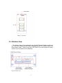
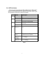
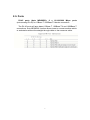
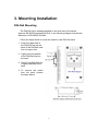
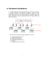
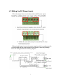
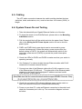
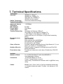
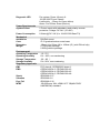
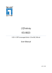
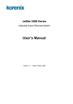
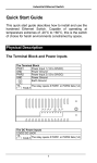
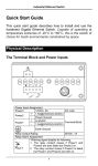
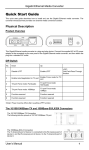
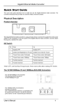
Industrial 8-port Gigabit Ethernet Switch
User’s Manual
-0-
Content
1. Introduction.....................................................2
1-1. Features................................................................2
1-2. Packing List...........................................................3
2. Hardware Description.....................................4
2-1. Dimensions............................................................4
2-2. Front Panel............................................................4
2-3. Bottom View...........................................................5
2-4. LED Indicators........................................................6
2-5. Ports.......................................................................7
3. Mounting Installation.......................................8
DIN-Rail Mounting..........................................................8
4. Hardware Installation......................................9
4-1. Wiring the DC Power Inputs..................................10
4-2. Wiring the Alarm Relay..........................................11
4-3. Wiring Earth Grounding.........................................11
4-4. Enabled the Event Alarm Function........................12
4-5. Cabling...................................................................13
4-6. System Power-On and Testing...............................13
5. Packet forwarding ability.................................16
5-1. Broadcast Control...................................................16
5-2. Quality of Service....................................................16
6. Trouble shooting..............................................18
7. Technical Specifications..................................19
-1-
1. Introduction
The 8-port compact Gigabit Ethernet switches particular packet forwarding
and filtering mechanism to fulfill industrial communications on the filed site. It
provides the graceful packet forwarding ability to handle 64~1552 packet size
into 2 priority queues which complies with quality of service for the best data
forwarding performance.
In addition, for the best network performance both of broadcast storm
filtering and flow control functions can ensure your data traffic deliver to
destination without traffic congestion.
To survive under hazard environments, it is equipped with 2 redundant
power inputs, as the wide range input avoiding any power interruption and
also operating between -10~70oC temperature range. For the easy
maintenance purpose, the switch has an alarm-relay for the port link event
and the power event to give an alarm to the service engineer on the filed site.
It will deliver you superiority and reliable performance on your filed site
applications.
This session introduces the following information:
1-1. Features
1-2. Packing list
1-1. Features
◎
◎
◎
◎
◎
◎
◎
◎
◎
◎
8 x 10/100/1000TX ports
Compact size with full power redundancy
Supports store-and-Forward switching architecture
QoS for packet forwarding precedence
Broadcast storm packet filtering
Port and power event alarm
IP-31 aluminum alloy case
DIN rail and wall mount
Dual power input DC12~48V
Compliance with IEEE Hi-Pot Testing
-2-
1-2. Packing List
The Industrial 8-port Gigabit Ethernet Switch is packaged with the following
items:
◎ Product
◎ CD : User Manual
Contact your sales representative if any item is missing or damaged.
-3-
2. Hardware Description
This session will introduce the hardware information as following:
2-1. Dimensions
2-2. Front Panel
2-3. Bottom View
2-4. LEDs of system and port
2-5. Connectors
2-1. Dimensions
The dimension of 8-port Industrial Fast Ethernet Rail Switch is 120 mm (H)
x 55 mm (W) x 108 mm (D). The following is the drawing of detail
mechanical design:
2-2. Front Panel
The Front Panel of the Industrial 8-port Gigabit Ethernet Switch is shown in
Figure A.
-4-
2-3. Bottom View
The bottom view of the Industrial 8-port Gigabit Ethernet Switch consists of
one 6-pin removable terminal block connector for two DC power inputs and
event alarm output. There is one 9-pin DIP SWITCH on the bottom for alarm
control of port or power event selection.
-5-
2-4. LED Indicators
There are some system diagnostic LEDs and Ethernet Port LEDs located
on the front panel of Industrial 8-port Gigabit Ethernet Switch. These LED
indicators provide administrators with real-time system status. Table-1 gives
the descriptions of the function of each LED indicator.
LED
PWR1
Status
Green on
Description
Power is on.
PWR2
Off
Green on
No power is being supplied.
Power is on.
Alm
Off
Red on
No power is being supplied.
Port link down or power failure event
occurred.
Port
1~8
Off
Link
(Green on )
No event.
A network device is detected and link
up.
Activity (Green
blinks)
The port is transmitting or receiving
packets from the TX device.
Speed
(Yellow on/
1000Mbps)
Speed
(Yellow off)
A network device is detected and link
on 1000Mbps.
A network device is detected and link
on 10/100Mbps.
Table-1
-6-
2-5. Ports
RJ-45 ports (Auto MDI/MDIX): 8 x 10/100/1000 Mbps
(auto-sensing RJ-45) for 10Base-T /100Base-TX device connection.
ports
The RJ-45 ports will auto-detect 10Base-T, 100Base-TX and 1000Base-T
connections. Auto MDI/MDIX function allows users to connect another switch
or workstation without the straight through cable or the crossover cable.
7
3. Mounting Installation
DIN-Rail Mounting
The DIN-Rail clip is already attached on the rear side of the switch
supports EN 50022 standard DIN Rail, in the following diagram includes the
dimension of EN 55022 DIN Rail.
Follow the steps below to mount the switch on the DIN-Rail track.
1. Insert the upper end of
the DIN-Rail clip into the
back of the DIN-Rail track
from its upper side
2. Lightly push the bottom
of the DIN-Rail clip into
the track.
3. Check if the DIN-Rail clip
is tightly attached to the
track.
4. To remove the switch
from the track, reverse
the steps above.
8
4. Hardware Installation
The following figure illustrates a typical application of the switch in field site.
It includes Enterprise communication backbone network, Factory
communication, field site communication and field site control layers. The
control equipments access and report production information through the
switch and uplink to factory communication level by copper which with
network redundancy.
This session will introduce the hardware installation, includes:
4-1. Wiring the DC Power Inputs
4-2. Wiring the Relay Alarm
4-3. Wiring Earth Grounding
4-4. Enable Alarm Relay Function
4-5. Cabling
4-6. System Power-On and Testing
9
4-1. Wiring the DC Power Inputs
Follow the steps below to wire the switch dual DC power inputs.
Before install power, be sure the power supply module is compliance with
UL certificated and the power system is shut down to avoid any damage.
About the wiring please refer following diagram.
10
4-2. Wiring the Alarm Relay
The switch provides one dry relay output for power or port link event. The
alarm relay default is “open” and form a close circuit when the even is
occurred. The relay conductor ability is 24W. When it connects with a DC 24V
power source, the maximum current is 1A. The following diagram shows how
to create an alarm circuit.
4-3. Wiring Earth Grounding
In the real fields, there are a lot of automatic devices, such as AC motors,
electric welding machine and power generator. Those devices will generate
electromagnetic and disturb communications. To prevent those noises, the
switch should be well earthed. The following diagram shows how to create a
connection.
11
4-4. Enabled the Event Alarm Function
This session will introduce how to configure and enable the event alarm to
alert maintenance engineer once the system event is occurred. The switch is
equipped with one dry relay output for port link fails or power fails. The
feature is controlled by digital control circuits. It effects immediately without
system reset when DIP SWITCH is changed.
On the bottom side of the switch, there is one 9-Pin DIP SWITCH for alarm
control. By inserting the port and power wiring to set up the alarm, the DIP
SWITCH of the intended Alarm is switched to “ON”. The relay output will form
a short circuit if the alarm occurred.
12
4-5. Cabling
The UTP cable connection between the switch and the attached devices
(switches, hubs, workstations, etc.) must be less than 100 meters (328 ft.) in
length.
4-6. System Power-On and Testing
1. Take the Industrial 8-port Gigabit Ethernet Switch out of the box.
2. To place the switch on the DIN-Rail track, please refer to the Mounting
Installation section.
3. Pull the terminal block off the switch and wire the power lines. Please
refer to the Wiring the DC Power Inputs section of how to wire the
power inputs.
4. PWR1 and PWR2 dual power inputs can be connected to power
sources simultaneously. When the primary power source fails (the
default setting is PWR1), the system will automatically switch to the
secondary power source (PWR2) to prevent the power interruption
occurred.
5. Check the LEDs for PWR1 and PWR2 to make sure that your switch is
operating normally.
6. Use Category-5 or above straight through Ethernet cables with RJ-45
connectors to connect network devices.
7. Connect one side of the Ethernet cable with a RJ-45 connector to one
of the Ethernet port (RJ-45 port). The other side of the Ethernet cable
connects to the target device equipped IP address and can handle
ICMP protocol as ping packet.
8. Check the port status LED indicator (blinking green) on the switch to
see if the network connection is established successfully.
9. Power on your host PC, make an Ethernet connection to the switch and
check the connected port is link up. The connection diagram is shown
as below:
13
10. To enable the “Command Line mode”. Click on Run in the Start
Menu Æ type Command Æ click OK to continue.
Type ping 192.168.1.1 command to check the connection. Here
uses 192.168.1.1 (IP address) as an example.
14
11. Repeat step 10 to make sure that the connection of each device
connected to the switch is successfully established.
12. Power on the PC host. Activate the Command Line mode and ping
the connected Ethernet device by typing “ping 192.168.1.1 –t”
command to see if it will respond. Do remember the PC host IP
address is same subnet address as the target device – 192.168.1.1.
13. The parameter-”t” allows you to continue to ping the network device.
Shown in the figure below.
Before you continue, make sure that both PWR1 and PWR2 are
successfully connected to power sources. When PWR1 fails, the LED for
PWR1 will go out. At the same time, if the ping command is still being replied
to, then it proves that the redundant power input function works normally.
15
5. Packet forwarding ability
The switch features packet filtering functions for broadcast packet control
protection and QoS. Both of features can provide more graceful performance
in a crowded network by traffic filtering and prioritize.
This session will introduce the principle of traffic control and forwarding
precedence, including “Broadcast control” and “Quality of Service”.
5-1. Broadcast Control
The switch begins to drop broadcast packets with DA ( destination address )
FF:FF:FF:FF:FF:FF if the received broadcast packets are more than the
threshold – 198 packets/ per second at 100Mbps or 19 packets / per second
at 10Mbps link speed.
All of ports are enabled with this function without any configuration to
provide a better network performance and prevent network congestion with
the flooding of broadcast packets.
5-2. Quality of Service
The switch supports frame type priority function High priority packet will be
queued to high priority queue to share more bandwidth. The ratio of
bandwidth of high priority and low priority queue is 8:1. 8 high priority packets
is progressed first, then the low priority packets will be progressed
afterwards.
The switch can examine the specific bits of VLAN Tag and TCP/IP TOS of
IPv4 and IPv6.
IEEE 802.1Q tag based CoS
The switch will examine the 3 bits of priority field carried by a VLAN tag and
maps it to the corresponding priority. A packet with priority field ranging from
0 to 3 will be treated as a low priority packet and will be stored in low priority
queue. A packet with priority field ranging from 4 to 7 will be treated as a high
priority packet, and will be stored in high priority queue.
16
IEEE 802.1Q Type of Service for IPv4 /IPv6 packet
The switch also provides the IP layer CoS (Class of Service) function by
recognizing the priority octet and mapping it to the corresponding priority. For
an IPv4 packet, it is embedded in the TOS (type of Service) Octet.
For an IPv6 data packet, the Traffic Class Octet is used to differentiate the
Class of Service. When this function is enabled, the swtich will automatically
recognize the IP version and capture the either the TOS field (IPv4) or Traffic
Class field (IPv6) and distributes the packet into High or Low Queue.
17
6. Trouble shooting
◎ Make sure you are using the correct DC power suppliers (DC12 to 48
V). Do not use power suppliers with DC output over 48V. It may
damage devices.
◎ Select Ethernet cables with specifications suitable for your
applications to set up your systems. Ethernet cables are categorized
into unshielded twisted-pair (UTP) and shielded twisted-pair (STP)
cables. Category 3, 4, 5, 6 Ethernet cables are suitable for systems
with 10 Mbps transmission speed. For systems with 100 Mbps
transmission speed, Category 5, 6 Ethernet cables are the only
suitable specifications for this environment. You also need to make
sure that the distance between each node cannot be longer than 100
meters (328 feet).
◎ If the power LEDs go off when the power cord is plugged in, a power
failure might be occurred. Check the power output connection to see if
there is any error at the power source. If you still cannot solve the
problem, contact your local dealer for assistance.
18
7. Technical Specifications
Technology
Standard
Switch Technology
System Performance
Aggregate System
Throughput
MAC Address
Packet Buffer
Jumbo frame
Transfer Packet Size
Broadcast storm
control
Class of Service
Quality of Service
Event alarm relay
Interface
Number of Ports
Connectors
Cables
IEEE802.3 10Base-T
IEEE802.3u 100Base-TX
IEEE 802.3ab 1000Base-T
IEEE802.3x flow control
Store and forward technology
11.904Mpps
4K MAC
192 KBytes
9KB
148,80pps for Ethernet 10Base-T
148,810pps for Fast Ethernet 100Base-TX
1,488,100pps for Fast Ethernet 100Base-TX
Packet size from 64~1552 Bytes ( Long Packet forwarding
ability)
Default enabled.
traffic threshold:
2000 packets/ Sec. @1000Mbps
200 packets/ Sec. @100Mbps
20 packets/Sec. @ 10Mbps
Provides 2 packet forwarding Queues: High Queue (4~7), Low
Queue (0~3) with 16:1 forwarding ratio.
Default Enabled. Supports VLAN tag priority and IPv4/IPv6
packet precedence.
Provides port and power event alarm; Enabled by 9-PIN DIP
switch.
8 x 10/100/1000 Base-TX with Auto MDI/MDI-X,
Auto-Negotiation function
10/100/1000 Base-TX: RJ-45
Power: Terminal block connector
Alarm relay: Terminal block connector with 1A @DC24V carry
ability.
RJ-45: Cat-3, Cat-4, Cat-5 or Cat-5e unshielded twisted pair
or shielded twisted pair cable. The Max. Link distance is 100
meters.
19
Diagnostic LED
Power Requirements
System Power
Power Consumption
Mechanical
Installation
Case
Dimension
Weight
Environmental
Operating Temperature
Operating Humidity
Storage Temperature
Storage Humidity
Regulatory Approvals
EMI
EMS
Shock
Vibration
Free Fall
MTBF
Per system: Power (Green) x2
10/100/1000TX port: Speed
Link/Activity (Green on/ Green blinks)
Alarm: Port /Power Event (Red on)
2 Power inputs with redundancy and polarity reverse
protection. Voltage: DC 24V (12~48V)
8 Watts @ DC 24V (8 x 10/100/1000 Base-TX)
DIN-Rail mount
IP-31 grade aluminum metal case
120mm(H) x 55mm (W) x 108mm (D) ( with DIN rail clip)
0.775kg with package
0.525kg without package
-10 ~70℃
0% ~ 95%, non-condensing
-20 ~ 85 ℃
5%~ 90%, non-condensing
FCC class A, CE/EN55022 class A.
CE/EN61000-4-2, CE/EN61000-4-3
CE/EN61000-4-4, CE/EN61000-4-5
CE/EN61000-4-6, CE/EN61000-4-8
IEC60068-2-27
IEC60068-2-6
IEC60068-2-32
100,000hours *MIL-HDBK-217F GB(MILITARY
HANDBOOK) standard
20