1
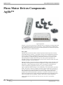
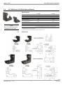
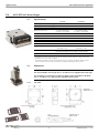
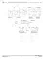
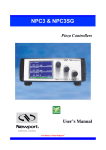
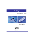
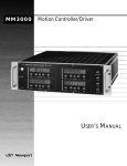
Piezo Motor Driven Components User’s Manual V2.2.x Agilis™ Series EDH0224En5030 — 11/15 Piezo Motor Driven Components ii Agilis™ Series Piezo Motor Driven Components Table of Contents Waranty ......................................................................................................... iv EU Declaration of Conformity ....................................................................... v Safety Prautions ............................................................................................ vi Warnings and Cautions ............................................................................... viii Piezo Motor Driven Components ............................................................... 1 1.0 1.1 1.2 AG-M050 and AG-M100 Optical Mounts .................................................. 2 Specifications.................................................................................................. 2 Dimensions ..................................................................................................... 2 2.0 2.1 2.2 AG-LS25-xx Linear Stages .......................................................................... 3 Specifications.................................................................................................. 3 Dimensions ..................................................................................................... 3 2.2.1 AG-LS25 ............................................................................................ 3 2.2.2 AG-LS25-27 ....................................................................................... 4 2.2.3 AG-LS25-27 Inserter for 1” Diameter Optics .................................... 4 3.0 3.1 3.2 AG-PR100 Rotation Stage ........................................................................... 5 Specifications.................................................................................................. 5 Dimensions ..................................................................................................... 5 4.0 4.1 4.2 4.3 4.4 4.5 4.6 4.7 AG-UC2 Piezo Controller ............................................................................ 6 Description...................................................................................................... 6 Modes of Operation ........................................................................................ 6 Getting Started ................................................................................................ 6 Local Operation .............................................................................................. 7 USB Communication ...................................................................................... 8 Agilis-Util Software ....................................................................................... 9 ASCII Command Set .................................................................................... 12 4.7.1 Syntax ............................................................................................... 12 4.7.2 Operating Modes .............................................................................. 13 4.7.3 State Diagram ................................................................................... 14 4.7.4 Command Set Summary .................................................................. 14 DL — Set step delay or get step delay setting ............................... 15 JA — Start jog motion or get jog mode ......................................... 15 MA — Measure current position ................................................... 16 ML — Set to local mode ................................................................ 17 iii EDH0224En5030 — 11/15 Agilis™ Series Piezo Motor Driven Components MR — Set to remote mode ............................................................ 17 MV — Move to limit ..................................................................... 18 PA — Absolute move .................................................................... 19 PH — Tell limit status ................................................................... 20 PR — Relative move ..................................................................... 20 RS — Reset controller ................................................................... 21 ST — Stop motion ......................................................................... 21 SU — Set step amplitude or get step amplitude setting................. 22 TE — Get error of previous command .......................................... 23 TP — Tell number of steps ............................................................ 23 TS — Get axis status...................................................................... 24 VE — Get controller firmware version ......................................... 24 ZP — Zero position ....................................................................... 25 5.0 AG-UC8 & AG-UC8PC Multi-Axis Piezo Controllers ........................... 26 5.1 Description.................................................................................................... 26 5.2 Modes of Operation ...................................................................................... 26 5.3 Motor Selection ............................................................................................ 26 5.4 Communication Type Selection (Available on AG-UC8PC Only).............. 27 5.4.1 USB Communication ....................................................................... 29 5.4.2 RS232 Communication .................................................................... 29 5.4.3 RS485 Communication .................................................................... 29 5.5 LED Indication ............................................................................................. 30 5.6 Agilis-Util Software ..................................................................................... 30 5.7 ASCII Command Set .................................................................................... 34 CC — Change channel................................................................... 34 Service Form .................................................................. Erreur ! Signet non défini. EDH0224En5030 — 11/15 iv Agilis™ Series Piezo Motor Driven Components Warranty Newport Corporation warrants this product to be free from defects in material and workmanship for a period of 1 year from the date of shipment. If found to be defective during the warranty period, the product will either be repaired or replaced at Newport’s discretion. To exercise this warranty, write or call your local Newport representative, or contact Newport headquarters in Irvine, California. You will be given prompt assistance and return instructions. Send the instrument, transportation prepaid, to the indicated service facility. Repairs will be made and the instrument returned, transportation prepaid. Repaired products are warranted for the balance of the original warranty period, or at least 90 days. Limitation of Warranty This warranty does not apply to defects resulting from modification or misuse of any product or part. This warranty also does not apply to fuses. This warranty is in lieu of all other warranties, expressed or implied, including any implied warranty of merchantability or fitness for a particular use. Newport Corporation shall not be liable for any indirect, special, or consequential damages. First printing 2009 Copyright 2012 by Newport Corporation, Irvine, CA. All rights reserved. No part of this manual may be reproduced or copied without the prior written approval of Newport Corporation. This manual is provided for information only, and product specifications are subject to change without notice. Any change will be reflected in future printings. v EDH0224En5030 — 11/15 Agilis™ Series Piezo Motor Driven Components EU Declaration of Conformity EDH0224En5030 — 11/15 vi Agilis™ Series Piezo Motor Driven Components Safety Precautions Definitions and Symbols The following terms and symbols are used in this documentation. European Union CE Mark CE Mark. The CE mark indicates that the equipment has been designed and tested to comply with all applicable European Union (CE) regulations. C-US CSA Mark CSA Mark. The presence of the C-US CSA mark indicates that the equipment has been designed, tested and certified as complying with all applicable US and Canadian safety standards. Direct Current (DC) Direct Current Symbol. This symbol indicates that the equipment is suitable for DC power only. The Agilis system is DC power only. Warnings and Cautions The following are definitions of the Warnings, Cautions and Notes that may be used in this manual to call attention to important information regarding personal safety, safety and preservation of the equipment, or important tips. WARNING Situation has the potential to cause bodily harm or death. CAUTION Situation has the potential to cause damage to property or equipment. NOTE Additional information the user or operator should consider. vii EDH0224En5030 — 11/15 Agilis™ Series Piezo Motor Driven Components General Warnings Observe these general warnings when operating or servicing this equipment: • Read all warnings on the unit and in the operating instructions. • Do not use this equipment in or near water. • Route cables so they are not likely to be damaged. • Do not use liquid or aerosol cleaners; use only a damp lint-free cloth. • To avoid explosion, do not operate this equipment in an explosive atmosphere. General Cautions Observe these cautions when operating or servicing this equipment: • Use only specified replacement parts. • Follow precautions for static sensitive devices when handling this equipment. • This product should only be powered as described in this manual. • There are no user-serviceable parts inside the Agilis system components. • If this equipment is used in a manner not specified within this manual, the protection provided by the equipment may be impaired. Manual Conventions The following conventions are used in this manual: • Acronyms appear on the first occurrence enclosed in parentheses following their definition. An acronym is a word formed from the initial letters of a string of words. Example: Read Only Memory (ROM). • Italics or boldface text are used as an alternative to quotation marks to highlight special text, such as keyboard keys, onscreen buttons, or text entries. Examples: Press Enter. AU command. EDH0224En5030 — 11/15 viii Agilis™ Series Piezo Motor Driven Components Warnings and Cautions PLEASE READ THE FOLLOWING RECOMMENDATIONS CAREFULLY BEFORE USING YOUR AG-UC2 CONTROLLER FOR THE FIRST TIME: CAUTION Do not place any Agilis component in a hostile environment such as X-Rays, hard UV or in a vacuum environment. Do not place a vacuum compatible Agilis component (V6) in a hostile environment or in a vacuum environment less than 10-6 hPa. CAUTION Do not leave this actuator in places subject to extremely high temperatures or low temperatures. This may cause an electric shock. • Operating temperature: +10 to +35 °C. • Storage temperature: -10 to +40 °C (in its original packaging). WARNING Do not introduce anything in the holes of AG-UC2 or AG-UC8 controllers, or spill any liquid on the product. WARNING Do not switch-on AG-UC2 or AG-UC8 controllers before connecting all the cables. WARNING Do not connect anything to AG-UC2 or AG-UC8 controllers except the cables provided by Newport for this specific product. CAUTION Our vacuum compatible Agilis components (V6) are delivered equipped with a vacuum compatible cable but a not vacuum compatible connector. So, the customer has to cut the cable, to use one part in vacuum environment and the other part to go from his feed-through to the controller. Customer has in charge to connect both part of this cut cable on its feed-through. WARNING Do not use AG-UC2 or AG-UC8 controllers after the unit experiences abnormal conditions that may compromise safety and functionality. Newport cannot be held liable if the above recommendations are not followed. CAUTION AG-UC8PC boards are very likely to be damaged by electrostatic discharge (ESD). Please use ESD protective measures when unpacking and handling these devices. ix EDH0224En5030 — 11/15 Agilis™ Series EDH0224En5030 — 11/15 Piezo Motor Driven Components x Agilis™ Series Piezo Motor Driven Components Piezo Motor Driven Components Agilis™ Agilis components. Newport’s new piezo motor driven components take a completely new design approach to the adjustments needed for many laser setups. Agilis components provide the ultrahigh adjustment sensitivity and convenient remote operation of a motorized component at the price and size of a manual mount! Why Agilis? Mechanical friction and the effects of human operation limit the precision of many optical adjustments. In theory, it is possible to achieve sub-µm adjustment sensitivity with very fine mechanics and differential screws. However, in practice, the lateral forces applied to a component during an adjustment often have an excessive effect, making alignments lengthy and frustrating. Also, many optical experiments are extremely sensitive to environmental factors and provide consistent results only when shielded well against external influences. Motorized mounts overcome the limits of manual components, but are typically costly and bulky, restricting their use for systems integration or simple remote operation in tight spaces. Agilis components provide a lower cost solution in a miniature size, without compromising adjustment sensitivity, speed, or position stability. Agilis components feature Newport’s new, proprietary, non-resonant piezo step direct motors. The motor is directly coupled to the moving platen. When idle, spring forces lock the position for true set and forget long-term stability. Agilis components have a faster adjustment speed than alternative screw driven designs and are free of the problems associated with backlash or hysteresis. In contrast to ultrasonic motors, the Agilis non-resonant motor concept makes small adjustments more predictable with its 50 nm incremental motion capability, ideal for ultra-sensitive optical alignments. Agilis components must be driven by the AG-UC2, AG-UC8 or AG-UC8PC controllers. 1 EDH0224En5030 — 11/15 Agilis™ Series 1.0 Piezo Motor Driven Components AG-M050 and AG-M100 Optical Mounts 1.1 Specifications AG-M050 Optics diameter AG-M100 0.5 in (12.7 mm) 1.0 in (25.4 mm) 0.16 to 0.24 in. (4 to 6 mm) 0.16 to 0.24 in. (4 to 6 mm) ±2° ±2° Adjustment sensitivity 2 μrad 1 μrad Absolute positioning Accuracy/Repeatability (1) (2) 0.05° 0.05° Allowable thickness of optics Angular range with models AG-M050L and AG-M100L Weight NOTE Cable length The V6 versions are vacuum compatible up to 10-6 hPa. 1) 2) 1.2 EDH0224En5030 — 11/15 25 g 85 g 1.2 m length, 4-wire mini-DIN connector. Can extend cable length using AG-MD4-1.5 extension cable. Max. position deviation before an MA command (measure absolute current position) and after a PA command (move to absolute position). Available with models AG-M050L(V6) and AG-M100L(V6) only. Dimensions 2 Agilis™ Series 2.0 Piezo Motor Driven Components AG-LS25-xx Linear Stages 2.1 Specifications Travel range AG-LS25 AG-LS25-27 0.47 in (12 mm) 1.06 in (27 mm) Minimum incremental motion (μm) (1) 0.05 0.1 Absolute positioning accuracy (μm) (2) 100 250 Maximum speed (mm/s) >0.5 with no axial load >0.2 with 1.7 N axial load 0.4 with no axial load 0.15 with 1.7 N axial load Max. normal load capacity (N) 3 (max. 40 mm cantilever) 2.5 (max. 40 mm cantilever) Holding force (N) 3 3 Axial load capacity (N) 2 1.5 Pitch, Yaw (μrad) 200 Material Limits Mechanical hard stops and precision electrical limits switch Weight [oz (g)] without cable: 2.5 (70) with cable: 3.4 (95) Cable 2) 2.2 without cable: 4.4 (125) with cable: 5.3 (150) 1.2 m length, 4-wire mini-Din connector. Can extend cable length using AG-MD4-1.5 extension cable. Life time 1) 200 Stainless steel >1000 m (>500,000 cycles of ±1 mm motion). The step size for forward and backward direction is adjustable. With default settings, the step size for the forward direction varies from the step size for the backward direction and may be larger than 50 nm. Individual steps are not 100% repeatable. For absolute positioning, the stage determines the average step size by counting the number of steps between the limits. The execution of an absolute positioning command may takes up to 80 s. Dimensions NOTE For XY assemblies of AG-LS25, use 4 x TC M3x4 screws supplied with each stage. For mounting AG-LS25 stages to B-Series adapter plates, M-SDS25 or M-DS25, use 4 x TC M2x4 screws plus washers supplied with each stage. 2.2.1 AG-LS25 3 EDH0224En5030 — 11/15 Agilis™ Series EDH0224En5030 — 11/15 Piezo Motor Driven Components 2.2.2 AG-LS25-27 2.2.3 AG-LS25-27 Inserter for 1” Diameter Optics 4 Agilis™ Series 3.0 Piezo Motor Driven Components AG-PR100 Rotation Stage 3.1 Specifications Optics diameter 1.0 in (25.4 mm) Max. optics thickness 0.40 in. (10 mm) Travel range 360° continuous Minimum incremental motion (1) 5 μrad (1 arcsec) Maximum speed 2 °/s Wobble 100 μrad Limits None Weigh 135 g Graduation 2° Cable 1) 3.2 1.2 m length, 4-wire mini-Din connector. Can extend cable length using AG-MD4-1.5 extension cable. The step size for forward and backward direction is adjustable. With default settings, the step size for the forward direction varies from the step size for the backward direction and may be larger than 5 μrad. Individual steps are not 100% repeatable. Dimensions 5 EDH0224En5030 — 11/15 Agilis™ Series 4.0 Piezo Motor Driven Components AG-UC2 Piezo Controller AG-UC2 Agilis controller. 4.1 Description The Agilis AG-UC2 controller provides convenient push button remote control and USB computer control of Agilis components. For each axis, two rows of push buttons are available for step size settings, precise low speed adjustments and fast coarse motion. Power is supplied through the USB port, either directly from the computer or from an independent USB power supply such as the USB-CH. A software utility allows mimicking remotely the operation of the controller buttons through the computer and selecting and operating a specific Agilis mount, as needed. A set of ASCII-commands and LabViewVI's for all functions are provided as well. 4.2 Modes of Operation The Agilis AG-UC2 provides two modes of operation. In local mode, default setting at power up, the push buttons are enabled and most computer functions are disabled (see table page 13). The local operation is described in detail in section 4.4. In remote mode all push buttons are disabled, and the controller can be fully operated from a PC, either from the supplied Agilis-Util software (see section 4.5 for details) or by sending ASCII commands (see section 4.6 for details). To switch from local to remote mode, use the Agilis-Util software (see section 4.4 for details) or send the command MR. To switch from remote to local mode, either close the Agilis-Util software, or connect to another controller through the software and send the ML command or disconnect and reconnect the controller to power. 4.3 Getting Started Connect the two cables from the Agilis optical mount to the AG-UC2 controller. Connect the Agilis controller to a powered USB port or to the USB power supply, Newport part number USB-CH. EDH0224En5030 — 11/15 6 Agilis™ Series Piezo Motor Driven Components AG-UC2 controller connectors. USB-CH USB power supply with changeable international power outlet adapters. 4.4 Local Operation Jog buttons. There are 6 jog buttons for each channel. Holding down any of the 6 buttons for less than one second results in a single step motion at the defined step amplitude. Otherwise holding a button for more than a second results in continuous motion at the designated button speed. On each row of buttons, the upper three buttons are assigned to the forward motion. When the lowest of the three button positions is pressed and held for more than one second, the motor moves at 5 steps/s. The medium button moves the piezo at 100 steps/s. The fastest forward motion at 1700 steps/s is performed with the top button position. The remaining three lower buttons on each row are assigned to the reverse motion direction. The third highest button position, enables 5 steps/s speed when pressed and held. The lowest button position provides the fastest motion at 1700 steps/s. The middle button provides 100 steps/s motion. 7 EDH0224En5030 — 11/15 Agilis™ Series Piezo Motor Driven Components Step amplitude (size) adjustment buttons. NOTE When using the step amplitude buttons, you must be able to sense the motion. Hence, you either must be in the high sensitivity range of your application or you need to use an external feedback sensor like a quad cell or an autocollimator to sense the motion of the mirror mount. There are 2 step size adjustment buttons for each channel. Forward (upper button) and reverse (lower button) buttons control the step amplitude adjustment. The default step size at power on is a medium step size. Pressing and holding a button initiates the amplitude selection beginning with a very low step amplitude. With every next step a slightly large step amplitude is used. When the button is released, the last step amplitude is saved until power up or the next adjustment is made. During the first couple of steps you may not sense any motion as the step amplitude might be too low to result in consistent motion. Hence, release the button only when sensing a real motion. Test the new step amplitude at different positions. When results are inconsistent, repeat the step amplitude adjustment and select a larger step amplitude. To restore the default step amplitude, power down the controller and then power it up. NOTE As in any open loop system, the step size is not always consistent. Agilis technology can provide the required sensitivity, but not necessarily repeatable steps in an open loop condition. However, a feedback sensor is recommended to fully utilize the functionality and sensitivity of the Agilis mirror mount system. A red LED indicates a detected limit switch. 4.5 USB Communication Using a Type A-A USB Cable. Install the software supplied with the CD on your PC. Apply the following settings to the COM port of your PC: • Baud Rate = 921600 • Data Bits = 8 • Parity = None • Stop Bits = 1 • Flow Control = None • Termination Character = CR/LF EDH0224En5030 — 11/15 8 Agilis™ Series Piezo Motor Driven Components 4.6 Agilis-Util Software The Agilis-Util software provides access to all functions of the Agilis controller. It is compatible with PC’s with a minimum of 64 MB of RAM and Windows 98, 2000, NT or XP operating system. To install the Agilis-Util software, load the distribution CD. The program gives you the option of where to load the files, or you can use the default directory C:\Program Files\Newport\AGILISTools\AGILIS-UC2 User Tool. After installation is complete, reboot your PC and open AgilisUserTool by doubleclicking on the newly created icon. The following image of the AG-UC2 controller will appear: Agilis-Util screen after start, no controller selected. A right mouse click anywhere in the window opens the main menu (except on keys or on the red cross). A right mouse click in the window opens the main menu. 9 EDH0224En5030 — 11/15 Agilis™ Series Piezo Motor Driven Components Click “Select controller”. The following window will open: Select a controller screen. In the figure above, one controller has been detected: You can change the controller name by simple typing into the Controller Name field, but you can not change the serial number. The serial number is a unique identifier of the controller hardware. The controller names are saved in a file on the PC. So when connecting the same controller to the same PC, the same controller name is displayed. Select a controller from the list and click “Connect”. When connected, the controller is in remote mode and the push buttons on the physical controller are disabled. The software window now looks like the following: Agilis-Util screen with a connected controller. You can now fully operate the controller from the software. The function of the jog buttons is exactly the same as though you were pressing the push buttons on the physical controller. See also chapter 4.4 for details. EDH0224En5030 — 11/15 10 Agilis™ Series Piezo Motor Driven Components A right mouse click in the window opens the main menu again. With “Select controller” you can select a new controller from the list. When selecting a different controller, the new controller is set to remote mode and the previous controller is set back to local mode. NOTE When running several Agilis-Util applications in parallel it is possible to select the same controller from different applications. However, this will generate an error as one controller can only be in remote mode to one application at any given time. NOTE The Agilis-Util software will not detect controllers that are connected to the computer after communication is first opened. To operate a new controller connected to your computer, close all Agilis-Util applications and start them again. NOTE In order to manage all connected controllers and open applications, the Agilis-Util software uses a temporary file ~AgilisDevices.TMP that is located in the same folder as the Agilis-Util software. In the unlikely event of a computer crash while an Agilis-Util software is open, this temporary file might not be removed from your computer. If this is the case, please delete this file manually and start your application again. When selecting “Relative move” from the main menu, the following window appears. Relative move screen. When selecting “Terminal” from the main menu, the following window will appear. In the Terminal screen, all ASCII commands can be used, see chapter 4.6 for details. Terminal screen. When selecting “Status” from the main menu, the following window will appear: For status information, please refer to the “TS” command details. 11 EDH0224En5030 — 11/15 Agilis™ Series Piezo Motor Driven Components Status screen. When selecting “Controller Version” from the main menu, the following window will appear: Controller version screen. When selecting “About” from the main menu, the following window will appear: About screen. 4.7 ASCII Command Set This section describes the two-letter ASCII commands that may be used to configure and operate the AG-UC2 controller when the controller is connected to a computer. These commands work with LabView, Visual Basic, C++ or any other computer application that can issue ASCII commands via a computer COM port. Newport’s Agilis-Util application, described in previous section of this manual, uses these commands. 4.7.1 Syntax The AG-UC2 is a command driven controller. The general format of a command is a two letter ASCII character preceded axis parameters and followed by parameters specific to the command: EDH0224En5030 — 11/15 12 Agilis™ Series Piezo Motor Driven Components Command format nn nn AA xx — Axis number (1 or 2). AA — Command name. xx — Optional or required value or “?” to query current value. Both, upper and lower case characters are accepted. Depending on the command, it can have an optional or required prefix (nn) for the axis number (1 or 2) and/or a suffix (xx) value or a “?”. Blank spaces Blanks are allowed and ignored in any position, including inside a numerical value. The following two commands are equivalent, but the first example might be confusing: 2 PR1 000 2PR1000 Command terminator Commands are executed as the command terminator CRLF (carriage-return line-feed, ASCII 13 and ASCII 10) is received. The controller will analyze the received string. If the command is valid and its parameters are in the specified range, it will be executed. Otherwise it will memorize an error. After the execution of the command, all remaining characters in the input string, if any, will be ignored. In particular, it is not possible to concatenate several commands on a single string from the PC. Each command will properly handle the memorization of related errors that can be accessed with the TE command. 4.7.2 Operating Modes The Agilis AG-UC2 provides two modes of operation. In local mode, default mode after powering up the controller, the push buttons are enabled and all commands that configure or operate the controller are disabled. Only commands that are used to monitor or diagnose the controller are enabled. In remote mode all push buttons are disabled, and all ASCII commands are enabled. To go from local mode to remote mode, use the command MR. To go from remote mode to local mode, use the command ML. 13 EDH0224En5030 — 11/15 Agilis™ Series Piezo Motor Driven Components 4.7.3 State Diagram The AG-UC2 uses different states for each axis. Not all commands are accepted in all states; see sections Command Set Summary for details. State diagram. 4.7.4 Command Set Summary Name Short Description DL Step delay JA Jog MA Measure position ML Local mode MR Remote mode MV Move to limit PA Absolute move PH Tell limit status PR Relative move RS Reset ST Stop motion SU Set step amplitude TE Get error TP Tell number of steps TS Get status VE Firmware version ZP Zero position 0 1 State 2 3 Set Type Query Modes Local Remote NOTE Commands MA, MV and PA require that the device has an electrical limit switch (e.g. model AG-LS25, AG-M050L, and AG-M100L). EDH0224En5030 — 11/15 14 Agilis™ Series Piezo Motor Driven Components Syntax DL — Set step delay or get step delay setting xxDLnn or xxDL? Parameters Description Range Input tests Description xx — Axis number. nn — Step delay or “?” xx — 1 or 2 nn — Integer between 0 and 200000 included. – Check controller is in remote mode. – Check the axis (1 or 2). – Check the current state of the axis (must be 0). – Check the format of the step delay (has to be an integer between 0 and 200000 included). Sets the step delay of stepping mode. The delay applies for both positive and negative directions. The delay is programmed as multiple of 10µs. For example, a delay of 40 is equivalent to 40 x 10 µs = 400 µs. The maximum value of the parameter is equal to a delay of 2 seconds between pulses. By default, after reset, the value is 0. JA — Start jog motion or get jog mode Syntax xxJAnn, or xxJA? Parameters Description Range Input tests Description Returns xx — Axis number. nn — Jog mode or “?” xx — 1 to 2 nn — -4, -3, -2, -1, 0, 1, 2, 3, 4, “?” – – – – Check controller is in remote mode. Check the axis (1 or 2). Check the current state of the axis. Check jog mode (integer ranging between -4 and 4). Starts a jog motion at a defined speed or returns jog mode. Defined steps are steps with step amplitude defined by the SU command (default 16). Max. amplitude steps are equivalent to step amplitude 50: -4 — Negative direction, 666 steps/s at defined step amplitude. -3 — Negative direction, 1700 steps/s at max. step amplitude. -2 — Negative direction, 100 step/s at max. step amplitude. -1 — Negative direction, 5 steps/s at defined step amplitude. 0 — No move, go to READY state. 1 — Positive direction, 5 steps/s at defined step amplitude. 2 — Positive direction, 100 steps/s at max. step amplitude. 3 — Positive direction, 1700 steps/s at max. step amplitude. 4 — Positive direction, 666 steps/s at defined step amplitude.. No return if jog mode is specified. If the sign “?” takes place of nn, this command returns the current jog mode. 15 EDH0224En5030 — 11/15 Agilis™ Series Piezo Motor Driven Components Errors Syntax 0 -2 -3 -4 -5 -6 — — — — — — No error. Axis out of range (must be 1 or 2). Wrong format for nn (must be integer). Wrong value for nn (must be -4, -3, -2, -1, 0, 1, 2, 3 or 4). Not allowed in local mode (controller must be in remote mode). Not allowed state (controller must be in state 0 or 2). MA — Measure current position xxMA Parameters Description xx — Axis number. Range xx — 1 or 2 – Check controller is in remote mode. – Check the current state of the axis. – Check the axis (1 or 2). Input tests Description Starts a process to measure the current position (see below). During the execution of the command, the USB communication is interrupted. After completion, the communication is opened again. The execution of the command can last up to 2 minutes. NOTE The MA command functions properly only with devices that feature a limit switch like models AG-LS25, AG-M050L and AG-M100L. Returns Errors EDH0224En5030 — 11/15 Returns the distance of the current position to the limit in 1/1000th of the total travel. 0 — No error. -2 — Axis out of range (must be 1 or 2). -3 — Wrong format for nn (must be integer). -5 — Not allowed in local mode (controller must be in remote mode). -6 — Not allowed state (controller must be in state 0). 16 Agilis™ Series Piezo Motor Driven Components Syntax Parameters Input tests Description ML — Set to local mode ML None. – – Check that axis is not specified. Check that parameter is not specified. Sets the controller to local mode. In local mode the pushbuttons on the controller are enabled and all commands that configure or operate the controller are disabled. To go to remote mode, use the MR command. At power-up the controller is always in local mode. Returns Errors Syntax Parameters Input tests Description Returns Errors None 0 — No error. -2 — Axis must not be specified. -3 — Parameter must not be specified. MR — Set to remote mode MR None. – – – Check that axis is not specified. Check that parameter is not specified. Check the current state of the two axes (need to be 0). Sets the controller to remote mode. In remote mode all commands are enabled and the pushbuttons on the controller are disabled. To go to local mode, use the ML command. None. 0 — No error. -2 — Axis must not be specified. -3 — Parameter must not be specified. -6 — The two axis must be in state 0. 17 EDH0224En5030 — 11/15 Agilis™ Series Piezo Motor Driven Components MV — Move to limit Syntax xxMVnn, or xxMV? Parameters Description Range Input tests Description xx — Axis number. nn — Jog mode or “?” xx — 1 or 2 nn — -4, -3, -2, -1, 0, 1, 2, 3, 4, “?” – Check controller is in remote mode. – Check the axis (1 or 2). – Check the current state of the axis (must be 0 or 3). – Check jog mode (integer ranging between -4 and 4 or ?). Starts a jog motion at a defined speed to the limit and stops automatically when the limit is activated. See JA command for details. NOTE The MA command functions properly only with devices that feature a limit switch like models AG-LS25, AG-M050L and AG-M100L. NOTE No motion will be executed when the limit switch is active. NOTE The MV-4 and MV4 commands are useful to calibrate the average step size at a certain step amplitude by counting the number of steps between the limits in forward and reverse direction. They are used as part of the MA and PA commands. In order to measure the number of steps between the limits, you can use the following sequence of commands: 1MV-3 Move to the negative limit. 1PH? If reply is 1PH1 or 1PH3, then: 1SUnn nn = value of step amplitude you want to use. 1ZP Reset step counter to zero. 1PR100 Move 100 steps. Needed to move out of the limit. MV4 Move to positive limit and stop. 1PH? If reply is PH1 or PH3, then: 1TP? Tell number of steps. The average step size in forward direction at the defined step amplitude is equal to the total available travel range (see data sheet) divided by the return of the TP command. NOTE Individual steps may not be 100% repeatable. NOTE When using a too low value for the step amplitude, the sequence may take a very long time and may not be very repeatable. Returns EDH0224En5030 — 11/15 No return if jog mode is defined. If the sign “?” takes place of nn, this command returns the current jog mode. 18 Agilis™ Series Piezo Motor Driven Components Errors 0 — No error. -2 — Axis out of range (must be 1 or 2). -3 — Wrong format for nn (must be integer). -4 — Wrong value for nn (must be -4, -3, -2, -1, 0, 1, 2, 3 or 4). -5 — Not allowed in local mode (controller must be in remote mode). -6 — Not allowed state (controller must be in state 0 or 3). PA — Absolute move Syntax xxPAnn, or xxPA? Parameters Description Range Input tests Description xx — Axis number. nn — Target position in 1/1000th of the total travel. xx — 1 or 2 – Check controller is in remote mode. – Check the axis (1 or 2). – Check the current state of the axis (must be ready). – Check target position (must be integer between 0 and 1000 included). Starts a process to move to an absolute position (see below). During the execution of the command, the USB communication is interrupted. After completion, the communication is opened again. The execution of the command can last up to 2 minutes. NOTE The PA command functions properly only with devices that feature a limit switch like models AG-LS25, AG-M050L and AG-M100L. Returns Errors xxPAnn at the end of motion. If the sign “?” takes place of nn, this command returns the current target position. 0 — No error. -2 — Axis out of range (must be 1 or 2). -3 — Wrong format for nn (must be integer). -4 — Wrong value for nn (must be between 0 and 1000 included). -5 — Not allowed in local mode (controller must be in remote mode). -6 — Not allowed state (controller must be in state 0). 19 EDH0224En5030 — 11/15 Agilis™ Series Piezo Motor Driven Components Syntax Parameters Input tests Description Returns PH — Tell limit status PH None. – Check controller is in remote mode. – Check that axis is not specified. – Check that parameter is not specified. Returns the limits switch status of the controller. Possible returns are: PH0 PH1 PH2 PH3 Description No limit switch is active Limit switch of channel #1 is active, limit switch of channel #2 is not active Limit switch of channel #2 is active, limit switch of channel #1 is not active Limit switch of channel #1 and channel #2 are active NOTE If the device has no limit switch, the return is always PH0. Errors Syntax 0 — No error. -2 — Axis must not be specified. -3 — Parameter must not be specified. -5 — Not allowed in local mode (controller must be in remote mode). PR — Relative move xxPRnn, or xxPR? Parameters Description Range xx — Axis number. nn — Number of steps. xx — 1 or 2 nn — Signed integer, between -2,147,483,648 and 2,147,483,647 (equivalent to long integer in C : [-2 -31, 2 31 - 1]). Input tests Description Returns Errors EDH0224En5030 — 11/15 – Check controller is in remote mode. – Check the axis (1 or 2). – Check the current state of the axis. – Check the number of steps (has to be integer, can be negative). Starts a relative move of nn steps with step amplitude defined by the SU command (default 16). If the sign “?” takes place of nn, this command returns the current target position. 0 — No error. -2 — Axis out of range (must be 1 or 2). -3 — Wrong format for nn (must be integer). -5 — Not allowed in local mode (controller must be in remote mode). -6 — Not allowed state (controller must be in state 0). 20 Agilis™ Series Piezo Motor Driven Components Syntax Parameters Input tests Description Returns Errors Syntax RS — Reset controller RS None. – Check that axis is not specified. – Check that parameter is not specified. Resets the controller. All temporary settings are reset to default and the controller is in local mode. None. 0 — No error. -2 — Axis must not be specified. -3 — Parameter must not be specified. ST — Stop motion xxST Parameters Description xx — Axis number. Range xx — 1 or 2 – Check controller is in remote mode. – Check the axis (1 or 2). – Check that parameter is not specified. Input tests Description Returns Errors Stops the motion on the defined axis. Sets the state to ready. None. 0 — No error. -2 — Axis out of range (must be 1 or 2). -3 — Parameter must not be specified. -5 — Not allowed in local mode (controller must be in remote mode). 21 EDH0224En5030 — 11/15 Agilis™ Series Piezo Motor Driven Components SU — Set step amplitude or get step amplitude setting Syntax xxSUnn, or xxSU+? or xxSU-? Parameters Description Range Input tests xx — Axis number. nn — Signed step amplitude or “+?” or “-?”. xx — 1 or 2 nn — Integer between -50 and 50 included, except zero. – Check controller is in remote mode. – Check the axis (1 or 2). – Check the current state of the axis (must be 0). – Check the format of the step amplitude (has to be an integer between -50 and 50 included, except zero). Description Sets the step amplitude (step size) in positive or negative direction. If the parameter is positive, it will set the step amplitude in the forward direction. If the parameter is negative, it will set the step amplitude in the backward direction. NOTE The step amplitude is a relative measure. The step amplitude corresponds to the amplitude of the electrical signal sent to the Agilis motor. There is no linear correlation between the step amplitude and the effective motion size. In particular, too low a setting for the step amplitude may result in no output motion. Also, the same step amplitude setting for forward and backward direction may result in different size motion steps. Also, the motion step size corresponding to a step amplitude setting may vary by position, load, and throughout the life time of the product. The step amplitude setting is not stored after power down. The default value after power-up is 16. This step size is used with the commands PR, JA1, JA4, MV1, and MV4, but not with JA2, JA3, MV2, and MV3. JA2, JA3, MV2, MV3 use the maximum step amplitude, equivalent to xxSU50 setting. Returns Errors EDH0224En5030 — 11/15 No return if step amplitude is specified. If ‘+?’ takes place of nn, this command returns the step amplitude setting in forward direction. If ‘-?’ takes place of nn, this command returns the step amplitude setting in backward direction. 0 — No error. -2 — Axis out of range (must be 1 or 2). -3 — Wrong format for nn (must be integer). -4 — Wrong value for nn (must be an integer between -50 and 50, not zero). -5 — Not allowed in local mode (controller must be in remote mode) -6 — Not allowed state (controller must be in state 0) 22 Agilis™ Series Piezo Motor Driven Components Syntax Parameters Input tests Description Returns TE — Get error of previous command TE None. – Check that axis is not specified. – Check that parameter is not specified. Returns the error code of the previous command. Each command generates an error code including “0” for NO ERROR. This error code can be queried with the TE command. For a safe program flow it is recommended to always query the command error after each command execution. The following error codes are defined: Error code of the previous command. The following error codes are defined: Error code 0 -1 -2 -3 -4 -5 -6 Errors Syntax Description No error Unknown command Axis out of range (must be 1 or 2, or must not be specified) Wrong format for parameter nn (or must not be specified) Parameter nn out of range Not allowed in local mode Not allowed in current state 0 — No error. -2 — Axis must not be specified. -3 — Parameter must not be specified. TP — Tell number of steps xxTP Parameters Description xx — Axis number. Range xx — 1 or 2 – Check controller is in remote mode. – Check the axis (1 or 2). – Check the status of the axis (must not be 3). – Check that parameter is not specified. Input tests Description Returns the number of accumulated steps in forward direction minus the number of steps in backward direction since powering the controller or since the last ZP (zero position) command, whatever was last. NOTE The step size of the Agilis devices are not 100% repeatable and vary between forward and backward direction. Furthermore, the step size can be modified using the SU command. Consequently, the TP command provides only limited information about the actual position of the device. In particular, an Agilis device can be at very different positions even though a TP command may return the same result. Returns TPnn, where nn is the number of accumulated steps in forward direction minus the number of steps in backward direction as Integer. 23 EDH0224En5030 — 11/15 Agilis™ Series Piezo Motor Driven Components Errors Syntax 0 — No error. -2 — Axis out of range (must be 1 or 2). -3 — Parameter must not be specified. -5 — Not allowed in local mode (controller must be in remote mode). -6 — Not allowed state (axis must not be in state 3). TS — Get axis status xxTS Parameters Description xx — Axis number. Range xx — 1 or 2 – Check the axis (1 or 2). – Check that parameter is not specified. Input tests Description Returns Returns the status of the axis. Possible returns are: Error code 0 1 2 Description Ready (not moving) Stepping (currently executing a PR command) Jogging (currently executing a JA command with command parameter different than 0). Moving to limit (currently executing MV, MA, PA commands) 3 Errors Syntax Parameters Input tests — No error. -3 — Parameter must not be specified. VE — Get controller firmware version VE None. – Check that axis is not specified. – Check that parameter is not specified. Description Returns the firmware version of the controller. Returns Returns the firmware version of the controller. Errors EDH0224En5030 — 11/15 0 0 — No error. -2 — Axis must not be specified. -3 — Parameter must not be specified. 24 Agilis™ Series Piezo Motor Driven Components Syntax ZP — Zero position xxZP Parameters Description xx — Axis number. Range xx — 1 or 2 – Check controller is in remote mode. – Check the axis (1 or 2). – Check the status of the axis (must be 0). – Check that parameter is not specified. Input tests Description Returns Errors Resets the step counter to zero. See TP command for further details. None. 0 — No error. -2 — Axis out of range (must be 1 or 2). -3 — Parameter must not be specified. -5 — Not allowed in local mode (controller must be in remote mode). -6 — Not allowed state (axis must not be in state 3). 25 EDH0224En5030 — 11/15 Agilis™ Series 5.0 Piezo Motor Driven Components AG-UC8 & AG-UC8PC Multi-Axis Piezo Controllers CAUTION AG-UC8PC boards are very likely to be damaged by electrostatic discharge (ESD). Please use ESD protective measures when unpacking and handling these devices. 5.1 Description Both Agilis AG-UC8 and AG-UC8PC controllers provide the capability to drive up to 8 piezoelectric motors. They can be powered through the USB port directly from the computer while the AG-UC8PC version can also be powered from an external power supply. A software utility allows driving the two selected motors at a time and switching from pair to pair. A set of ASCII-commands and LabViewVI's for all functions are provided. 5.2 Modes of Operation Both controllers can be fully operated from a PC, either from the supplied Agilis Software Utility (see section 5.5 for details) or by sending ASCII commands (see section 5.6 for details). 5.3 Motor Selection AG-UC8PC Controller Board. EDH0224En5030 — 11/15 26 Agilis™ Series Piezo Motor Driven Components AG-UC8 Controller. Both Multi-Axes Agilis Controller versions are able to control up to 8 piezoelectric motors. Multi-Axes Agilis controllers drive piezoelectric motors by pairs. The “CC” command allows selecting the desired motor. For example, to control motor number 8 (Axis 2 on channel 4), one has to select pair number 4 with the command “CC4” and then use the index of the second motor of the pair, for example, “2PR500” to execute a relative move of 500 steps. 5.4 Communication Type Selection (Available on AG-UC8PC Only) The AG-UC8PC controller is able to communicate through 3 different protocols: USB, RS232, or RS485. The board has a dedicated USB connector and a HE10 connector where the two RS protocols are available (see below table for connector pins assignment). 27 EDH0224En5030 — 11/15 Agilis™ Series Piezo Motor Driven Components On the AG-UC8PC version, jumpers on the electronic board do the communication type selection. For each communication type, only one set of jumpers should be placed at a time. Jumper Set COM JS1 (1&2, 3&4) RS232 JS2 (5&6, 7&8) RS485 JS3 (9&10, 11&12) USB The required connections schemes depending on the jumper location is indicated on the figure below. Communication parameters are indicated in the table below. Protocol Speed Jumper RS232 115200 JS1 RS485 115200 JS2 USB 921600 JS3 Pin # Description 1 RS232 - Rx 2 RS232 - Tx 3 RS485 - Tx+ 4 RS485 - Tx- 5 RS485 - Rx+ 6 RS485 - Rx- 7 GND 8 GND 9 Power supply +5 V 10 Power supply +5 V WARNING Never plug anything on the USB cable when power is supplied through the external J2 connector. EDH0224En5030 — 11/15 28 Agilis™ Series Piezo Motor Driven Components 5.4.1 USB Communication Using a Type A-mini USB Cable Install the software supplied with the CD on your PC and check that JS3 jumpers are set on pins 9&10 and 11&12. Apply the following settings to the COM port of your PC: • Baud Rate = 921600 • Data Bits = 8 • Parity = None • Stop Bits = 1 • Flow Control = None • Termination Character = CR/LF 5.4.2 RS232 Communication Install the software supplied with the CD on your PC and check that JS1 jumpers are set on pins 1&2 and 3&4. Apply the following settings to the COM port of your PC: • Baud Rate = 115200 • Data Bits = 8 • Parity = None • Stop Bits = 1 • Flow Control = None • Termination Character = CR/LF 5.4.3 RS485 Communication Install the software supplied with the CD on your PC and check that JS2 jumpers are set on pins 5&6 and 7&8. Apply the following settings to the COM port of your PC: • Baud Rate = 115200 • Data Bits = 8 • Parity = None • Stop Bits = 1 • Flow Control = None • Termination Character = CR/LF CAUTION In order to communicate through the RS232 or RS485 protocols, provide the power supply through the J2 connector and configure the selection jumpers accordingly. CAUTION Mating connectors or equivalent can be used. 29 EDH0224En5030 — 11/15 Agilis™ Series Piezo Motor Driven Components 5.5 LED Indication The LED can display green or orange to show states: Green Orange Solid No axis in the limit / No axis moving 1 or 2 axes in the limit / No axis moving Blinking No axis in the limit / 1 or 2 axes moving 1 or 2 axes in the limit / 1 or 2 axes moving CAUTION If there is no communication, please check the led status and check if the jumpers are correctly configured. 5.6 Agilis-Util Software The Agilis-Util software provides access to all functions either on the AG-UC2 and AG-UC8 controllers. The Agilis-Util software provides access to all functions of the Agilis controller. It is compatible with PC’s with a minimum of 64 MB of RAM and Windows 98, 2000, NT or XP operating system. To install the Agilis-Util software, load the distribution CD. The program gives you the option of where to load the files, or you can use the default directory C:\Program Files\Newport\AGILISTools\AGILIS-UC2 User Tool. After installation is complete, reboot your PC and open AgilisUserTool by doubleclicking on the newly created icon. The following image of the AG-UC2 controller will open: Agilis-Util screen after start, no controller selected. EDH0224En5030 — 11/15 30 Agilis™ Series Piezo Motor Driven Components A right mouse click in the window opens the main menu. A right mouse click in the window opens the main menu. Click “Select controller”. The following window will open: Select controller screen. In the figure above, one controller has been detected: You can change the controller name by simple typing into the field, but you can not change the serial number. The serial number is a unique identifier referring to the hardware of the controller. The controller names are memorized in a file on the PC. So when connecting the same controller to the same PC, the same controller name is displayed. Select a controller from the list and click “Connect”. When connected, the controller is ready to work on the default selected channel (Channel #1 in the example below): 31 EDH0224En5030 — 11/15 Agilis™ Series Piezo Motor Driven Components Agilis-Util screen with a connected controller. You can now fully operate the controller from the software. You can select another pair of motors by scrolling down and selecting from channel #1 to channel #4 as shown below: When selecting “Relative move” from the main menu, the following window opens. Relative move screen. EDH0224En5030 — 11/15 32 Agilis™ Series Piezo Motor Driven Components When selecting “Terminal” from the main menu, the following window will open. In the Terminal screen, all ASCII commands can be used, see chapter 4.6 for details. Terminal screen. When selecting “Status” from the main menu, the following window will open: For status information, please refer to the “TS” command details. Status screen. When selecting “Controller Version” from the main menu, the following window will open: Controller version screen. When selecting “About” from the main menu, the following window will open: About screen. 33 EDH0224En5030 — 11/15 Agilis™ Series Piezo Motor Driven Components 5.7 ASCII Command Set NOTE Both AG-UC8 and UC8PC controllers feature the same set of commands as the AG-UC2 controller, so please refer to chapter 4.7.4 for details on available commands. The “CC” command is the only command specific to the AG-UC8/UC8PC multi-axes controllers (see details of this command below). Syntax CC — Change channel CCnn, or CC? Parameters Description nn — Channel number. Range nn — 1 to 4 – Check the controller is AG-UC8. – Check controller is in remote mode. – Check there is no background task (MA, PA). – Check the current state of both axes (must be 0). – Check channel number (must be integer). Input tests Description This command is specific to AG-UC8. The piezo actuators are selected by pairs which are grouped in four channels. This command changes the selected channel. Returns None. Errors 0 — No error. -1 — Unknown command (only available on AG-UC8). -2 — Must not specify any channel. -3 — Wrong format for nn (must be integer). -4 — Wrong value for nn (must be between 0 and 4 included). -5 — Not allowed in local mode (controller must be in remote). -6 — Not allowed state (both axes must be in state 0). NOTE For a particular actuator selection (1 to 8), the range nn (1 to 4) specifies a channel number in CC commands. The axis number xx (1 or 2) is specified in other commands. For example, to control actuator number 8 (Axis 2 on channel 4), one has to select the channel number 4 with the command “CC4” and then use the index of the second actuator of the channel, for example, “2PR500” to execute a relative move of 500 steps. • Channel 1: Actuators 1 and 2 (xx = 1, 2) • Channel 2: Actuators 3 and 4 (xx = 1, 2) • Channel 3: Actuators 5 and 6 (xx = 1, 2) • Channel 4: Actuators 7 and 8 (xx = 1, 2) EDH0224En5030 — 11/15 34 Agilis™ Series Piezo Motor Driven Components Service Form Your Local Representative Tel.: __________________ Fax:___________________ Name: _________________________________________________ Return authorization #: ____________________________________ (Please obtain prior to return of item) Company:_______________________________________________ Address: ________________________________________________ Date: __________________________________________________ Country: ________________________________________________ Phone Number: __________________________________________ P.O. Number: ____________________________________________ Fax Number: ____________________________________________ Item(s) Being Returned:____________________________________ Model#: ________________________________________________ Serial #: ________________________________________________ Description: ________________________________________________________________________________________________________ Reasons of return of goods (please list any specific problems): ________________________________________________________________ __________________________________________________________________________________________________________________ __________________________________________________________________________________________________________________ __________________________________________________________________________________________________________________ __________________________________________________________________________________________________________________ __________________________________________________________________________________________________________________ __________________________________________________________________________________________________________________ __________________________________________________________________________________________________________________ __________________________________________________________________________________________________________________ __________________________________________________________________________________________________________________ __________________________________________________________________________________________________________________ __________________________________________________________________________________________________________________ __________________________________________________________________________________________________________________ __________________________________________________________________________________________________________________ __________________________________________________________________________________________________________________ __________________________________________________________________________________________________________________ __________________________________________________________________________________________________________________ __________________________________________________________________________________________________________________ __________________________________________________________________________________________________________________ __________________________________________________________________________________________________________________ __________________________________________________________________________________________________________________ __________________________________________________________________________________________________________________ __________________________________________________________________________________________________________________ __________________________________________________________________________________________________________________ __________________________________________________________________________________________________________________ __________________________________________________________________________________________________________________ __________________________________________________________________________________________________________________ __________________________________________________________________________________________________________________ 35 EDH0224En5030 — 11/15 Visit Newport Online at: www.newport.com North America & Asia Newport Corporation 1791 Deere Ave. Irvine, CA 92606, USA Sales Tel.: (800) 222-6440 e-mail: [email protected] Technical Support Tel.: (800) 222-6440 e-mail: [email protected] Service, RMAs & Returns Tel.: (800) 222-6440 e-mail: [email protected] Europe MICRO-CONTROLE Spectra-Physics S.A.S 9, rue du Bois Sauvage 91055 Évry CEDEX France Sales Tel.: +33 (0)1.60.91.68.68 e-mail: [email protected] Technical Support e-mail: [email protected] Service & Returns Tel.: +33 (0)2.38.40.51.55