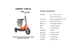
1
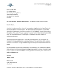
Letter of Transmittal October 14th, 2014 Dr. Andrew Rawicz School of Engineering Science Simon Fraser University Burnaby, British Columbia V5A 1S6 Re: ENSC 440 and 305W Functional Specification for the VIA: Visually Impaired Assistant Dear Dr. Rawicz, You will find enclosed the functional specifications for the VIA: Visually Impaired Assistant. It is our hope to develop a system to help the visually impaired navigate their way through everyday life in a more efficient manner. We drive to provide them with a greater amount of information about the environment around them. A better solution than the current white cane is in great need and our goal is to improve on this present result. This functional specifications’ purpose is to provide high-‐level design descriptions, proof-‐of-‐ concept, and many of the requirements of our product. As well, we hope to outline the sustainability and safety of our design. Sensible Solutions is composed of three engineering students of a strong and determined mind-‐set: Ahmad Ibrahim, Robert Sanchez, and Jessica Zanewich. We appreciate you taking the time to analyze our functional specifications. If there are any questions or concerns regarding this document, please feel free to contact us by email at [email protected]. Sincerely, Jessica Zanewich Chief Executive Officer Functional Specification for the VIA: Visually Impaired Assistant Project Team: Ahmad Ibrahim Jessica Zanewich Robert Sanchez Contact Person: Jessica Zanewich Submitted to: Dr. Andrew Rawicz – ENSC 440 Steve Whitmore – ENSC 305 School of Engineering Science Simon Fraser University Issued Date: October 14th, 2014 Revision: 1.1 Executive Summary Expanding the possibilities and depth-‐of-‐field of the visually impaired is highly desired. They are unfortunately limited to only a couple of valid options in the current market. There are an estimated 285 million people who are regarded as visually impaired worldwide [1]. With the VIA, we at Sensible Solutions are hoping to change a large portion of these visually impaired people approach the world. Our objective is to create a remote-‐like device for a more compact and accurate solution. The hope is to use audio feedback through a speaker to indicate obstacles. This will give an indication of how far the obstacle is from the person and what kind of obstacle it is. It will give the visually impaired a larger awareness radius. With our design, we are taking some very important measures into consideration. Specifically, our aim is to give the greatest radius possible, but this must also stay very accurate. Size and form factor is also a very great consideration. With a comfortable ability to hold the device, it will be a product worth having. Our product will go through three phases of design, and we will proceed with development as followed: Stage 1 – Functional Prototype: 1. The functionality and placement of the ultrasonic sensors will be outlined. 2. The distance measurements of the ultrasonic sensors will be tested and evaluated. 3. All components will be integrated, though not all may be used for the time being. 4. Identification of obstacles will be introduced. Stage 2 – Prototype Refinement/Marketable Product: 1. Identification of objects will be solidified, and continually tested. 2. Audio for feedback control will be implemented through speakers on the device. 3. Accelerometer/gyroscope functionality will be integrated into the system. 4. An on/off switch, and control buttons will be integrated onto the device. 5. A clip-‐on wired for hearing audio in noisy environments will be added. 6. The design of the device will be evaluated for ergonomic-‐related improvements. Stage 3 – Final Product: 1. LED indicators, as a visually impaired warning system will be added. 2. A headphone jack will be added, for those users who prefer to use earphones/headphones. 3. Software robustness, and reliability will be improved. Standards for each of the components of our design, as well as for the product itself is something we will be using heavily throughout the process of creation. A proof-‐of-‐concept will be delivered by December 2nd, 2014 to keep with the required deadlines set forth for the project. Our first goal is to keep the user safe and able to feel comfortable moving with ease in the space around them. i Table of Contents Executive Summary ................................................................................................................................................... i List of Figures ............................................................................................................................................................. iii Glossary ......................................................................................................................................................................... iv 1. Introduction ............................................................................................................................................................ 1 1.1 Scope .............................................................................................................................................................. 1 1.2 Intended Audience ................................................................................................................................... 1 1.3 Classification ............................................................................................................................................... 1 2. System Requirements ......................................................................................................................................... 2 2.1 System Overview ........................................................................................................................................... 2 2.2 General Requirements ................................................................................................................................ 3 2.3 Physical Requirements ............................................................................................................................... 3 2.4 Electrical Requirements ............................................................................................................................. 3 2.5 Mechanical Requirements ......................................................................................................................... 4 2.6 Environmental Requirements ................................................................................................................. 4 2.7 Reliability and Durability Requirements ............................................................................................ 4 2.8 Standards .......................................................................................................................................................... 4 2.9 Safety Requirements .................................................................................................................................... 4 2.10 Performance Requirements ................................................................................................................... 4 2.11 Usability Requirements ........................................................................................................................... 5 2.12 Luxury Functions ........................................................................................................................................ 5 3. Microcontroller ...................................................................................................................................................... 6 3.1 Component Overview .................................................................................................................................. 6 3.2 General Requirements ................................................................................................................................ 6 3.3 Physical Requirements ............................................................................................................................... 6 3.4 Electrical Requirements ............................................................................................................................. 6 3.5 Reliability and Durability Requirements ............................................................................................ 7 3.6 Performance Requirements ..................................................................................................................... 7 4. Ultrasonic Sensors ................................................................................................................................................ 8 4.1 Component Overview .................................................................................................................................. 8 4.2 General Requirements ................................................................................................................................ 8 4.3 Physical Requirements ............................................................................................................................... 8 4.4 Safety Requirements .................................................................................................................................... 8 4.5 Performance Requirements ..................................................................................................................... 8 5. Audio Feedback System ..................................................................................................................................... 9 5.1 Component Overview .................................................................................................................................. 9 5.2 General Requirements ................................................................................................................................ 9 5.3 Physical Requirements ............................................................................................................................... 9 5.5 Reliability and Durability Requirements ............................................................................................ 9 5.6 Standards .......................................................................................................................................................... 9 5.7 Usability Requirements .............................................................................................................................. 9 6. Accelerometer/Gyroscope ............................................................................................................................. 10 6.1 Component Overview ............................................................................................................................... 10 6.2 General Requirements ............................................................................................................................. 10 6.3 Reliability and Durability Requirements ......................................................................................... 10 ii 6.4 Safety Requirements ................................................................................................................................. 10 6.5 Performance Requirements .................................................................................................................. 10 7. Software ................................................................................................................................................................. 11 7.1 General Requirements ............................................................................................................................. 11 7.2 Reliability and Durability Requirements ......................................................................................... 11 7.3 Safety Requirements ................................................................................................................................. 11 7.4 Performance Requirements .................................................................................................................. 11 8. User Documentation ......................................................................................................................................... 12 8.1 Overview ........................................................................................................................................................ 12 8.2 General Requirements ............................................................................................................................. 12 8.3 Usability Requirements ........................................................................................................................... 12 9. System Test Plan ................................................................................................................................................ 13 9.1 Microcontroller ........................................................................................................................................... 13 9.2 Software ......................................................................................................................................................... 13 9.3 Ultrasonic Sensors ..................................................................................................................................... 13 9.4 Audio Feedback System .......................................................................................................................... 14 9.5 Accelerometer/Gyroscope ..................................................................................................................... 14 9.6 LED External Warning System ............................................................................................................. 14 10. Conclusion .......................................................................................................................................................... 15 11. References .......................................................................................................................................................... 16 List of Figures Figure 1 -‐ Block diagram of the VIA's main components .......................................................................... 2 Figure 2 -‐ State machine of the VIA .................................................................................................................... 3 Figure 3 -‐ Main Microcontroller Input and Output Components .......................................................... 6 Figure 4 -‐ Ultrasonic sensors mounted on the VIA ..................................................................................... 8 Figure 5 -‐ Audio System Feedback Flow Chart ............................................................................................. 9 iii Glossary Accelerometer – Measures acceleration Adafruit Trinket Pro – Referred to as Trinket; The microcontroller used in the marketable, and final product Arduino Uno – Referred to as Arduino; The microcontroller used during prototyping stages Bluetooth -‐ A standard for the short-‐range wireless interconnection of cellular phones, computers, and other electronic devices Braille – Written language used by the visually impaired; represented by patterns of raised dots Embedded System – A computer system with a dedicated function GPS – Global Positioning System Gyroscope – Determines orientation with respect to the force of gravity Microcontroller – A small computer designed to govern embedded systems operations MM – Millimeter(s) MS – Millisecond(s) PCB – Printed circuit board Proof of concept – a demonstration in principle, whose purpose is to verify that some concept or theory has the potential of being used S – Second(s) Ultrasonic Sensor – Sensors working off the principle of radar, or sonar V – Voltage VIA – Visually Impaired Assistant Watchdog timer – An electronic timer used to detect, and recover from computer malfunctions iv 1. Introduction The Visually Impaired Assistant, or the VIA, is a handheld device created by Sensible Solutions. The product uses ultrasonic sensors to detect and identify nearby objects, as well as give an approximation of the distance the obstacle is from the user through a small speaker. It is a more expensive option than the currently used white cane, but with much more information provided to the user to make navigation easier. The system must meet the requirements of the user, as well as the standards set in place for the different components used. These requirements will be outlined in the following documentation. 1.1 Scope This functional specifications document will provide an in-‐depth look into the VIA system. The document will outline the proof-‐of-‐concept model requirements, the features of the product, a test plan implementation, and finally the safety, standards and sustainability of the VIA. It will also give a review of the specific stages of our design, specifically the difference between our proof-‐of-‐concept model and our intended final working prototype. This document will be used throughout the implementation, design and development of the VIA system. 1.2 Intended Audience This document is intended for a wide range of persons involved in the implementation of the VIA. Any member of the Sensible Solutions team, specifically the CTO, designers, and testers, can use the functional specifications. The Chief Technical Officer can use this as a standards and safety guide when conducting training for the use of certain components. The designers can utilize the requirements set forth to keep with what is expected for the VIA proof-‐of-‐concept and prototype. Finally, the testers may use this document and the test plan found within as a manual for proper function of different components. 1.3 Classification The following convention will be used when listing functional requirements: [Rn – P] Functional Specification n – denotes the The values of P are as such: nth functional requirement I High Priority; Required for the proof of concept/prototype model P – denotes the II Moderate Priority; Aimed to be implemented for the priority; value working/marketable model ranges from I to IV III Low Priority; Aimed to be implemented for the consumer product IV Future Consideration; Not intended to be implemented as part of the first consumer product, may be implemented in future consumer releases 1 2. System Requirements 2.1 System Overview The VIA is a handheld electronic device used to help the visually impaired maneuver through different obstacles in their day-‐to-‐day lives. This is done in three key steps: gather data from the peripherals, processing the data, and audio feedback, as shown in figure 1. Figure 1 -‐ Block diagram of the VIA's main components The peripherals of which the data is gathered from are the four ultrasonic sensors, an accelerometer, and a gyroscope. Between these six components, the microcontroller will have all of the data needed to accurately determine the location of obstacles in the direction that the VIA is being pointed. For stage 1, and the first half of stage 2, the processing is done using an Arduino Uno, an Adafruit Trinket Pro will be used in the latter half of stage 2, and stage 3 – the reason is outlined in section 9.1. The microcontroller will be programmed to then interpret, and analyze this data to accurately distinguish between different obstacles the user may encounter. These obstacles will include, but are not limited to stairs, curbs, inclines, objects, and holes. The audio feedback system is comprised of an external memory card, and the feedback system. There are three possible audio feedback systems: a mounted speaker, and a clip on speaker, and a headphone jack. The external memory card is needed to store sound clips that will be used to specify any oncoming obstacles. Also, if the clip-‐on speakers, or the headphone jack is in use, the mounted speaker will be turned off. A diagram of the VIA states is shown in figure 2. 2 Figure 2 -‐ State machine of the VIA All of these components will fit into a compact, and ergonomic case. Making the device handheld allows for a smooth transition from the white cane while giving the user freedom to check for obstacles up to 6 meters in front of them. This encasement will also come with a sleek wrist strap to help avoid accidental drop damage, and misplacements. 2.2 General Requirements [R1 – I] [R2 – I] [R3 – III] [R4 – IV] The device shall be intuitive to use, and has a gentle learning curve. The device shall make correct readings, and calculations regardless of the user’s height. The final production cost shall be less than CDN$200 per unit. The final production cost shall be less than CDN$150 per unit. 2.3 Physical Requirements [R5 – II] [R6 – I] [R7 – II] [R8 – II] The device shall be ergonomically optimized regarding the device’s size, shape, and weight as to not cause the user discomfort during prolonged use. The device shall not impede the user’s movements. The device shall allow for the attachment of wrist straps/lanyards to prevent drops. All components, and wirings shall be encapsulated within the device’s casing. 2.4 Electrical Requirements [R9 – I] [R10 – III/IV] [R11 – I] [R12 – III] The device shall be powered via 4 AA batteries. The device shall be powered via a rechargeable lithium-‐ion battery pack. The device shall have a rocker switch for its power switch. The device shall have a fuse to prevent electrical surges. 3 2.5 Mechanical Requirements [R13 – II] [R14 – II] Switches and buttons shall be rigid enough to prevent accidental changes, yet easily useable by the user. The battery cover shall use a sliding mechanism to minimize the effect of continuous use, and wear on the case. 2.6 Environmental Requirements [R15 – I] [R16 – II] [R17 – II] [R18 – II] [R19 – II] The device shall operate under most indoor conditions. The device shall operate under ideal outdoor conditions. The device shall operate between -‐20°C to 40°C [2]. The device shall operate between 40% and 90% relative humidity [3]. The device shall be water resistant. 2.7 Reliability and Durability Requirements [R20 – I] [R21 – I] [R22 – III] [R23 – IV] [R24 – II] [R25 – III] The device shall not output any false positives. The device shall output all confirmed readings. The device shall run for 4 consecutive hours on a single charge. The device shall run for 8 consecutive hours on a single charge. The device shall withstand drops of 1.5 meters. The device shall withstand drops of 2.0 meters. 2.8 Standards [R26 – II] [R27 – II] [R28 – II] The device shall comply with IEC 60529 Degrees of protection provided by enclosures (IP Code) standards [4]. The device shall comply with IEC 60085 Electrical insulation standards [5]. The device shall comply with IEC 60086 Primary batteries standards [6]. 2.9 Safety Requirements [R30 – I] [R31 – III] [R32 – II] [R33 – II] [R34 – III] All components shall be grounded. The device shall be well insulated. The audio feedback volume shall be controlled via volume buttons. Others around the user shall be notified of the user’s visual impairment. The device shall notify the user of the battery charge dropping to 20%. 2.10 Performance Requirements [R35 – I] [R36 – II] [R37 – I] [R38 – III] [R39 – I] [R40 – I] The device shall be able to distinguish obstacles within 500 ms of detection. The device shall be able to distinguish obstacles within 100 ms of detection. The device shall give audio feedback within 50 ms of distinguishing obstacles. The device shall respond to buttons being pressed within 50 ms. The device shall take 4 readings per second from each ultrasonic sensor. The device shall have an obstacle detection accuracy of ±1 inch. 4 2.11 Usability Requirements [R41 – II] [R42 – III] [R43 – IV] [R44 – IV] The device shall be able to determine, and compensate for the user’s height within 1 s of the device powering on, and being held in the correct position. The device shall be easily serviceable by trained individuals. The device shall be easily serviceable by untrained individuals using a manual. The device shall not require more than an annual calibration check/service. 2.12 Luxury Functions [R45 – IV] [R46 – IV] [R47 – IV] Sensors with an accuracy of ±1 mm shall be integrated into the device. GPS functionality shall be integrated into the device for navigation purposes. Bluetooth functionality shall be integrated into the device for audio feedback purposes. 5 3. Microcontroller 3.1 Component Overview The main purpose of the microcontroller is to facilitate the obstacle detection and to send audio feedback to the user. Data is obtained from the ultrasonic sensors, accelerometer, and gyroscope, and is then processed. If an obstacle is detected, the appropriate audio clip is obtained from the external memory, and played on the appropriate audio feedback speaker. The components and microcontroller interaction is outlined in figure 3. Aside from these core functions, the microcontroller will also be used to rhythmically flash LED lights, to indicate the visual impairment of the user. Figure 3 -‐ Main Microcontroller Input and Output Components 3.2 General Requirements [R48 – I] [R49 – I] The microcontroller shall be able to run Arduino code. The microcontroller shall have enough memory to store the software. 3.3 Physical Requirements [R50 – I] The microcontroller shall have enough pins to accommodate all of the peripherals. 3.4 Electrical Requirements [R51 – I] [R52 – II] The microcontroller shall require no more than 5 V to operate. The microcontroller shall be able to power all of the peripherals without additional electrical components. 6 3.5 Reliability and Durability Requirements [R53 – III] The microcontroller shall be able detect malfunctions, and initiate a device reset. 3.6 Performance Requirements [R54 – I] The microcontroller shall have a faster clock than all peripherals, and components. 7 4. Ultrasonic Sensors 4.1 Component Overview The VIA is designed to have four ultrasonic sensors mounted on it, sending proximity readings with a one inch resolution to the microcontroller. Three of the sensors will be pointed towards the ground on a single axis, yet at different angles. These three sensors will be use to detect low obstacles such as a bag or a curb. The fourth sensor will gather proximity data directly in front of the user. This sensor will mainly be used to detect and anticipate oncoming people or walls. Figure 4 shows how the ultrasonic sensors are mounted on the device. Figure 4 -‐ Ultrasonic sensors mounted on the VIA 4.2 General Requirements [R55 – I] The sensors shall have longer range than the average white cane (1.0–1.5 meters). 4.3 Physical Requirements [R56 – II] The sensors shall not protrude past the device’s casing. 4.4 Safety Requirements [R57 – I] [R58 – I] The sensors shall not cause interference with external electronics. The sensors shall not cause interference with internal components. 4.5 Performance Requirements [R59 – I] [R60 – II] The sensors shall take 4 readings per second. The sensors will be able to take readings regardless of water resistant features; openings might be obstructed to make the device water resistant. 8 5. Audio Feedback System 5.1 Component Overview The audio feedback system, as seen in figure 5, will be used only when an obstacle is detected. Once this has happened, the microcontroller must fetch the appropriate sound clip from memory, and then play it on the appropriate speaker. Figure 5 -‐ Audio System Feedback Flow Chart 5.2 General Requirements [R61 – I] [R62 – II] [R63 – III] [R64 – IV] The device shall use a device-‐mounted speaker(s). The device shall use a clip-‐on speaker. The device shall have an audio jack for audio feedback purposes. The device shall have a Bluetooth system to sync with audio devices. 5.3 Physical Requirements [R65 – II] The clip-‐on speakers shall not impede the user’s movements. 5.5 Reliability and Durability Requirements [R66 – II] [R67 – III] [R68 – II] The audio feedback shall be clear, and understandable. The device-‐mounted speakers shall last the lifetime of the device, or easily serviceable. The clip-‐on speakers shall be easily replaceable. 5.6 Standards [R69 – II] [R70 – II] The device shall comply with IEC 60065 Audio, video and similar electronic apparatus – Safety requirements standards [7]. The device shall comply with IEC 60651 Sound level meters [8]. 5.7 Usability Requirements [R71 – II] [R72 – II] The volume of the audio feedback system shall be controlled via device-‐ mounted buttons. The clip-‐on speakers shall not cause damage to the user’s clothing while clipped on. 9 6. Accelerometer/Gyroscope 6.1 Component Overview The accelerometer and gyroscope are key components of the VIA that will help not only detect obstacles, but anticipate when the user will reach the obstacle. The gyroscope will be used to collect data on the angle that the user is holding the VIA. Combining this data with the knowledge of the fixed angles of each of the ultrasonic sensors, the microcontroller will be able to accurately measure the user’s distance from the obstacle. The accelerometer is also used alongside the ultrasonic sensors to approximate the users walking velocity. Given the user’s velocity and the distance to an obstacle, the VIA will be able to predict when the user will encounter said obstacle, and provide an appropriate notification. For the remainder of section 6, the accelerometer/gyroscope shall be referred to as ‘the peripheral’. 6.2 General Requirements [R73 – I] [R74 – II] The peripheral shall make readings independent of the microcontroller. The peripheral shall determine the orientation of the device while running. 6.3 Reliability and Durability Requirements [R75 – I] The peripheral shall last the lifetime of the device. 6.4 Safety Requirements [R76 – I] The peripheral shall have an accuracy of 95%. 6.5 Performance Requirements [R77 – I] [R78 – I] The peripheral shall be able to make 4 readings per second. The peripheral shall output readings within 10 ms after the request is made by the microcontroller. 10 7. Software 7.1 General Requirements [R79 – I] The software updates shall not require hardware changes. 7.2 Reliability and Durability Requirements [R80 – I] The software shall not have memory management issues. 7.3 Safety Requirements [R81 – I] [R82 – II] [R83 – III] [R84 – III] The software shall produce warnings when appropriate. The software shall not produce false positives. The software shall detect hardware malfunctions, and compensate accordingly. The software shall have a watchdog timer. 7.4 Performance Requirements [R85 – I] The software’s performance shall not be affected by the runtime duration. 11 8. User Documentation 8.1 Overview A user manual is included with each device. This manual will aid the user in setting up, utilizing, and troubleshooting their device. Two versions of the manual will be provided, one in plain text, and the other in braille. 8.2 General Requirements [R86 – III] [R87 – III] [R88 – IV] The user documentation shall be one all-‐inclusive user guide, which includes the warranty, disclaimer, user manual, troubleshooting, and contact information. The user documentation shall be in English. The user documentation shall be in French. 8.3 Usability Requirements [R89 – III] [R90 – III] The user documentation shall include a braille copy. The user documentation shall include a printed copy. 12 9. System Test Plan To ensure a high quality design and execution of the product, we will be following a bottom up testing approach. This approach requires an intensive unit testing stage, where each component will be tested individually. We then proceed into integration testing, where each component will be integrated into the system individually. Each stage of development will have an overall test to ensure the unit is working correctly before moving onto the next stage. Using these techniques and timelines for our testing will ensure a solid working device with very few errors to be found in the final product. 9.1 Microcontroller Since the Adafruit Trinket Pro is a vital component, as it will ensure that we are able to make the ergonomic constraints of the device. Since we will be doing a great amount of component testing, integration, and prototyping with the Arduino Uno we have to ensure that our system is seamlessly ported into the trinket, which will entail extensive software testing through simulations, and physical testing of the device. A lot of the early stage development is done on the Arduino due to the Trinket requiring components to be soldered on. A large portion of the Trinket testing happens in the latter half of stage two, and all of stage three (refer to the executive summary for the description of each stage). Since we aim to only integrate the Trinket once everything is working on the Arduino, most of the aforementioned testing will be refining the system, and getting it ready for the final product. 9.2 Software The software build for this device is very important. We will be conducting two different types of testing done on the software, unit tests, and a system test. A test simulation is written for each component that extensively tests the software of each specific peripheral of the device. Individual software design, and analysis has been outlined, with specifics, in the individual testing descriptions. The second type of testing software is the overall checks, or system testing. Only one software program may be used on the microcontroller, which means each of the individual pieces must come together. This process will be continuous, as it begins with one component, and after individual testing of the next part, it can be added to the current software program for further testing. The system testing after all of the software has been included must be extensive, and must involve retesting each component, as well as the device as a whole. 9.3 Ultrasonic Sensors For testing of the ultrasonic sensors, a software program must be created to measure distances with each individual sensor. After the validity of each sensor has been tested, a second program must be written to test the distance measurements of all four sensors when used together. This program must take into account the limitations of the sensors [9], and prevent internal interference since the sensors only function in one frequency, 42 KHz [9]. 13 Many different surfaces, objects/obstacles, and distances must be used in the testing of the ultrasonic sensors to ensure the warnings are accurate. Sensors may need to be moved to many different placements throughout the testing of the device to provide the best readings possible. 9.4 Audio Feedback System The testing of the audio component of our system will consist of both a sound, and memory part. The audio is strongly associated with the readings of the ultrasonic sensors. After the ultrasonic sensor testing has produced precise readings, the readings must be used in the testing of the audio. For efficiency, we will test the audio feedback system by running software simulations, while also testing the ultrasonic sensors -‐ the integration of the two systems at this point should be trivial. Due to the limitations of the Arduino Uno, and Adafruit Trinket Pro the audio feedback system requires the use of an SD memory card to store the audio files. Hence, extension of the software framework must be performed to allow for proper storage, and retrieval of sound clips from the memory card. The aforementioned retrieved sound clip(s) are based on the readings of the ultrasonic sensors. The audio is the last implementation for the proof-‐of-‐concept model and will very likely require re-‐testing of the other components to produce a well-‐functioning device. The headphone jack that is a possible final product component should not affect other components and only require slight hardware retooling, and some minor audio tests. 9.5 Accelerometer/Gyroscope Testing of the accelerometer and gyroscope will have 3 phases. The first phase will consist of assuring both the accelerometer and the gyroscope function individually. This will initially begin by writing a program that will simply output the tilt angle of the gyroscope. The output angle will be compared to the expected readings. Another program will then be written to test that accelerometer readings are consistent with what is expected. The accelerometer and gyroscope are on a single chip and use the same pins; this means the second phase of testing will involve confirming both components can simultaneously output accurate results. The final phase involves integrating the fully functional accelerometer and gyroscope with the ultrasonic sensors. At this point, it is expected that all of the individual components can simultaneously run without any problems. 9.6 LED External Warning System The LED testing component is extremely small as it is hardware-‐based. A simple on/off switch will be linked to the LED, which can be easily tested by using the switch. However, we would want to implement a buzzer to indicate the light is on so a person who is visually impaired will know the light is on. 14 10. Conclusion Sensible Solutions is well on its way to developing the VIA, or Visually Impaired Assistant; a device that will help the visually impaired navigate safely and confidently in their surrounding environment. The functional specifications and requirements established above not only clearly define what the VIA is intended do, but also indicate priorities of different features. A proof-‐of-‐concept is being developed at this time and is expected to meet all of the high priority requirements mentioned in this document. With the gradual completion of each feature of the device, the VIA will be able to evolve from a simple prototype to a fully marketable product. 15 11. References 1. World Health Organization. (2014, August). Visual Impairment and Blindness [Online]. Available: http://www.who.int/mediacentre/factsheets/fs282/en/ 2. Statistics Canada. (2007, October 12). Weather Conditions in Capital and Major Cities [Online]. Available: http://www.statcan.gc.ca/tables-‐tableaux/sum-‐ som/l01/cst01/phys08b-‐eng.htm 3. Current Results. Average Annual Humidity at Canadian Cities [Online]. Available: http://www.currentresults.com/Weather/Canada/Cities/humidity-‐annual-‐ average.php 4. Thompson Reuters TechStreet. (2013, August 29). Degrees of protection provided by enclosures (IP Code) CONSOLIDATED EDITION [Online]. Available: http://www.techstreet.com/products/1864271?product_id=1864271&sid=goog&g clid=CjwKEAjwk_OhBRD06abu3qSoxlwSJACt7sZ7nX7HUFSVwPLmOq0Lc7sftEX4Sr 4hV75f1u0uIU0P6BoCwEHw_wcB 5. International Electrotechnical Commission. (1957, January 1). Recommendations for the classification of materials for the insulation of electrical machinery and apparatus in relation to their thermal stability in service [Online]. Available: http://webstore.iec.ch/webstore/webstore.nsf/standards/IEC%2060085!opendoc ument 6. International Electrotechnical Commission. (2011, February 17). Primary Batteries – Part 1: General [Online]. Available: http://webstore.iec.ch/webstore/webstore.nsf/artnum/044867!opendocument 7. International Electrotechnical Commission. (2012, January 16). Audio, Video, Similar Electronic Apparatus: Safety Requirements [Online]. Available: http://www.drzamps.com/documents/etl_web_report.pdf 8. NoiseMeters Canada. Sound Level Meter Standards [Online]. Available: http://www.noisemeters.ca/help/faq/standards.asp 9. MaxBotix Inc.. LV-‐MaxSonar-‐EZ1 High Performance Sonar Range Finder [Online]. Available: http://maxbotix.com/documents/MB1010_Datasheet.pdf 16