1
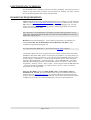
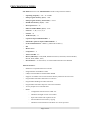
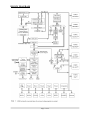
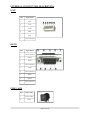
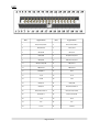
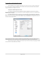
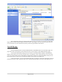
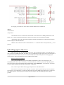
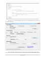
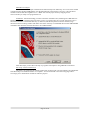
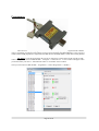
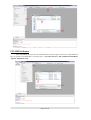
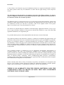
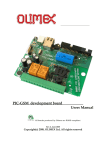
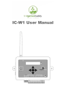
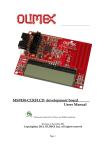
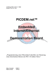
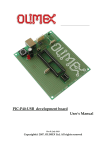
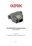
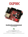
PIC-WEB REV.C development board User's Manual All boards produced by Olimex are ROHS compliant Rev. D, August 2014 Copyright(c) 2013, OLIMEX Ltd, All rights reserved Page 1 of 35 INTRODUCTION PIC-WEB is a compact (65×60 mm) board which is supported by Microchip’s open source TCP-IP stack AN833. The board is designed with 64-pin high-performance, 1 Mbit Flash microcontroller with Ethernet – PIC18F67J60 and supports: SLIP, ARP, IP, ICMP, TCP, UDP, HTTP, DHCP, FTP. The Microchip stack is written very modular and flexible and you can enable or disable modules and supports dynamic web pages which give you the possibility to control all PIC resources remotely via FTP, HTTP, UDP, TCP etc. With this board you can implement web and ftp server, send e-mails and almost everything what the big servers do. The on board 1Mbit serial flash is available for data storage. This board is designed to have Web page of no more than 128 kB. If you want a lot of images in your application you can also host them on other server visible on the network where you have the PIC-WEB connected. The potential of the board is to generate a fluid communication between some specific sensors or actuators across a TCP/IP net including the controls of it. The Microchip stack is an open source library, which is possible to modify and compile at any time. But you will probably need to modify it to your own needs. The board comes with an implemented WEB server and a web page that let you controls some of the features of the board. In this manual we’ll learn about how to compile the TCP/IP stack to use it over the platform, the needed software, how to use the pre loaded web page, and how to upload your own web pages in the board. This manual requires Microsoft Windows© OS because several software units used here are Windows compatible only. BOARD FEATURES PIC18F67J60 microcontroller 1Mbit on board serial flash for web pages storage ICSP/ICD mini connector for programming and debugging with PIC-ICD2, PICICD2-POCKET and PIC-ICD2-TINY. Reset button User event button Analogue trimmer potentiometer Thermistor for temperature monitoring RS232 driver and connector Complete web server and TCP-IP stack support as per Microchip's open source TCP-IP stack Power plug-in jack for +9 to +12 VDC power supply Voltage regulator +3.3V and filtering capacitors status LED UEXT connector Extension header to connect to other boards PCB: FR-4, 1.5 mm (0,062"), solder mask, silkscreen component print Dimensions 60×65 mm (2.36×2.55") Page 2 of 35 ELECTROSTATIC WARNING The PIC-WEB board is shipped in protective anti-static packaging. The board must not be subject to high electrostatic potentials. General practice for working with static sensitive devices should be applied when working with this board. BOARD USE REQUIREMENTS Cables: Depends on the used programming/debugging tool. It could be 1.8 meter USB A-B cable to connect PIC-ICD2, PIC-ICD2-POCKET or PIC-KIT3 to USB host on PC or Serial DB9 cable in case of PIC-ICD2-TINY or other programming/debugging tools. You will need a serial cable if not for programming, than for configuring the board. You will also need a Crossover Ethernet cable. Note: PIC-KIT3 is recommended for new designs since PIC-ICD2 programmers are not supported in Microchip's MPLAB X IDE. If you don't mind using MPLAB 8.xx then PICICD2 is also a good choice. Hardware: Programmer/Debugger – most of Olimex programmers are applicable, for example PIC-ICD2, PIC-ICD2-POCKET, PIC-ICD2-TINY, PIC-Kit3 or other compatible programming/debugging tool. For programming PIC-WEB Rev. C, you will also need PIC-ICSP connector. !!!Warning!!! When you want to program this microcontroller with PIC-ICD2, PIC-ICD2POCKET or PIC-ICD2-TINY, before connecting the programmer to your target board, you should first connect the programmer to your computer and open MPLAB. There, first from menu Configure – Select Device – choose the microcontroller you are about to program, then from menu Programmer – Select Programmer – choose MPLAB ICD 2, wait while MPLAB is downloading operation system, and after ICD2 is connected – check in menu Programmer – Settings – Power – there is option – Power target circuit from MPLAB ICD 2 – this option should be forbidden, you could not select it. Now it is safe to connect the programmer to your target board. Software: PIC-WEB is tested with MPLAB IDE v.8.87 + C18 compiler 3.40 Free Standard EVAL Version. The latest modified stack version we tested the board with is TCP/IP stack 5.42 (www.microchip.com). It is possible that the stack might not function properly if used with later versions of MPLAB IDE. You will also need a terminal program configured at 19 200 bps, 8N1 and XON/XOFF flow control (it's described below). Page 3 of 35 PROCESSOR FEATURES PIC-WEB board uses CPU PIC18F67J60 from Microchip with these features: Operating Frequency – DC – 41.67 MHz Flash program memory (bytes) – 128k Flash program memory (Instructions) – 65532 SRAM data memory (bytes) – 3808 Interrupt Sources – 26 Ethernet TX/RX Buffer (bytes) – 8192 I/O Ports – A, B, C, D, E, F, G I/O Pins – 39 10-Bit A/D (ch) – 11 Capture/Compare/PWM Modules – 2 Enhanced Capture/Compare/PWM Modules – 3 Serial Communications – MSSP (1), Enhanced USART (1) SPI Master I2C™ Comparators – 2 Timers 8/16-Bit – 2/3 Resets (and Delays) - POR, BOR, RESET Instruction, Stack Full, Stack Underflow, MCLR, WDT (PWRT, OST) Instruction Set – 75 Instructions, 83 with Extended Instruction Set Enabled Ethernet Features: IEEE 802.3 compatible Ethernet Controller Integrated MAC and 10Base-T PHY 8-Kbyte Transmit/Receive Packet Buffer SRAM Supports one 10Base-T Port with Automatic Polarity Detection and Correction Programmable Automatic Retransmit on Collision Programmable Padding and CRC Generation Programmable Automatic Rejection of Erroneous Packets Activity Outputs for 2 LED Indicators Buffer: Configurable transmit/receive buffer size Hardware-managed circular receive FIFO Byte-wide random and sequential access Internal DMA for fast memory copying Hardware assisted checksum calculation for various protocols Page 4 of 35 MAC: Support for Unicast, Multicast and Broadcast packets Programmable Pattern Match of up to 64 bytes within packet at user-defined offset Programmable wake-up on multiple packet formats PHY: Wave shaping output filter Loopback mode Flexible Oscillator Structure: Selectable System Clock derived from single 25 MHz external source: 2.78 to 41.67 MHz Internal 31 kHz Oscillator Secondary Oscillator using Timer1 @ 32 kHz Fail-Safe Clock Monitor: Allows for safe shutdown if oscillator stops Two-Speed Oscillator Start-up Peripheral Highlights: High-Current Sink/Source: 25 mA/25 mA on PORTB and PORTC Five Timer modules (Timer0 to Timer4) Four External Interrupt pins Two Capture/Compare/PWM (CCP) modules Three Enhanced Capture/Compare/PWM (ECCP) modules: One, two or four PWM outputs Selectable polarity Programmable dead time Auto-shutdown and auto-restart Up to two Master Synchronous Serial Port (MSSP) modules supporting SPI (all 4 modes) and I2C™ Master and Slave modes Up to two Enhanced USART modules: Supports RS-485, RS-232 and LIN 1.2 Auto-wake-up on Start bit Auto-Baud Detect 10-Bit, up to 16-Channel Analog-to-Digital Converter module (A/D): Auto-acquisition capability Conversion available during Sleep Dual Analog Comparators with Input Multiplexing Special Microcontroller Features: 5.5V Tolerant Inputs (digital-only pins) Page 5 of 35 Low-Power, High-Speed CMOS Flash Technology: Self-reprogrammable under software control C compiler Optimized Architecture for re-entrant code Power Management Features: Run: CPU on, peripherals on Idle: CPU off, peripherals on Sleep: CPU off, peripherals off Priority Levels for Interrupts 8×8 Single-Cycle Hardware Multiplier Extended Watchdog Timer (WDT): Programmable period from 4 ms to 134s Single-Supply 3.3V In-Circuit Serial Programming™ (ICSP™) via two pins In-Circuit Debug (ICD) with 3 Breakpoints via two pins Operating Voltage Range of 2.35V to 3.6V (3.14V to 3.45V using Ethernet module) On-Chip 2.5V Regulator Page 6 of 35 BLOCK DIAGRAM Page 7 of 35 MEMORY MAP for PIC18F67J60 Page 8 of 35 SCHEMATIC RST R8 V+ 6 3 C1- V- 4 C2+ 5 C2- RS232 DB9_female 6 7 8 9 1 C1+ 2 14 7 1 2 3 4 5 13 8 R1IN R2IN C22 100nF 20pF C4 C23 100nF 20pF C5 11 10 T1IN T2IN T1OUT T2OUT CTS R24 RTS 12 9 R1OUT R2OUT 16 VCC Q1 25MHz/5X3,2MM R9 GND_ 1M 39 40 GND 46 47 T PINT PIN+ TXD1 EXT-29 200R RXD1 EXT-30 T POUT - 50 T POUT + 51 BH34S R10 BH34S 2k/1% U3PWR 15GND 18 3.3V U3 MAX3232 C20 100nF C21 100nF 7 RST 53 270/1% C6 10 220nF 3.3V 3.3V R11 26 38 57 C24 100nF C7 100nF C8 C9 100nF 100nF 9 25 41 56 3.3V C10 100nF 3.3V C12 100nF R12 330 C13 10uF/6.3V 52 45 54 55 3.3VA 19 C14 20 100nF 24 23 22 21 28 27 RA0/LEDA/AN0 RA1/LEDB/AN1 RA2/AN2/VREFRA3/AN3/VREF+ RA4/T0CKI RA5/AN4 ENVREG OSC1/CLKI OSC2/CLKO TPOUTTPOUT+ RBIAS VDDCORE/VCAP VDD VDD1 VDD2 VSS VSS1 VSS2 VSS3 VSSTX VSSRX AVDD AVSS EXT-12 EXT-13 EXT-14 BH34S R13 BH34S 560 BH34S EXT-15 BH34S C17 L2 ferrite_bead R14 49.9/1% 100nF R15 49.9/1% T POUT + C15 10pF Q2 C16 EXT-8 BH34S 10pF T POUT LEDA 32768/6pF GN D SCK SDI SDO T XD1 RXD1 SCL SDA UEXT _#CS 17 16 15 14 13 12 11 8 RF1/AN6/C2OUT RF2/AN7/C1OUT RF3/AN8 RF4/AN9 RF5/AN10/CVREF RF6/AN11 RF7/#SS1 RG4/CCP5/P1D VDDPLL VSSPLL PGC PGD 2 1 64 63 62 61 RE0/P2D RE1/P2C RE2/P2B RE3/P3C RE4/P3B RE5/P1C VDDTX VDDRX 3.3V 60 59 58 RD0/P1B RD1/ECCP3/P3A RD2/CCP4/P3D LED red BUT 30 29 33 34 35 36 31 32 RC0/T1OSO/T13CKI RC1/T1OSI/ECCP2/P2A RC2/ECCP1/P1A RC3/SCK1/SCL1 RC4/SDI1/SDA1 RC5/SDO1 RC6/TX1/CK1 RC7/RX1/DT1 BH34S BH34S BH34S BH34S EXT-1 EXT-2 EXT-3 EXT-4 3 4 5 6 44 43 42 37 RB0/INT0/FLT0 RB1/INT1 RB2/INT2 RB3/INT3 RB4/KBI0 RB5/KBI1 RB6/KBI2/PGC RB7/KBI3/PGD TPINTPIN+ LEDA LEDB AN_T RIM AN_T EM P #EE_CS LEDB EXT-9 EXT-10 EXT-11 BH34S BH34S BH34S EXT-5 EXT-6 EXT-7 EXT-21 EXT-22 EXT-23 BH34S BH34S BH34S BH34S BH34S BH34S EXT-24 EXT-25 BH34S BH34S EXT-26 EXT-27 BH34S BH34S EXT-28 BH34S R17 R16 R19 49.9/1% T PIN+ R18 49.9/1% T PIN- LAN 1 3 2 AG KG AY KY 7 6 8 TD+ TCT TDAG KG AY KY RD+ RCT RD- 1:1 75 75 YELLOW 1:1 75 75 GREEN 1nF/2kV RJLD-043TC C18 100nF 3.3V ICSP RST C19 100nF PGD PGC 1 2 3 4 5 6 WU06S PIC18F67J60 R1 VIN G1 DB104(SMD) PWR C11 100nF + 3.3V 49 48 3.3V #MCLR 3.3V 0.68 R2 3.3V 3.3V 3.3V 3.3V VSS TC C2 SC SE FB 3.3V_E D1 1N5819 5 4 390pF EXT-33 EXT-34 1 L1 CL150uH/SW68 1 2 BH34S BH34S BH34S BH34S EXT-31 EXT-32 SCL_E 2 1 C3 R4 3K/1% PWR_LED RED 1000uF/6.3V/8mm/ESR U1 MC34063AD_SMD_MBR R3 0R 3.3VA 330 R5 1.8K/1% R6 560 EXT-17 3.3V BH34S EXT-18 3.3V BH34S EXT-19 BH34S EXT-20 C25 100nF BUT T1157 AN_TR 10K R28 33K 2 1 open VIN TEMP TERMISTOR BUT R27 4.7K RXD1 SDA SDO UEXT_#CS 3.3V 3.3VA R20 10K R21 2 4 6 8 10 SDA_E BH34S 3.3V 3.3V TXD1 SCL SDI SCK 1 3 5 7 9 open + 3 IS DC VCC + C1 470uF/16V UEXT BH10S R26 4.7K 3.3VA 2 6 7 8 0.68 YDJ-1136 9-12VDC R22 330 AN_T RIM C26 100nF U4 AN_T EM P R23 10K R25 100K C27 SDO 1 SI SCK 2 SCK GND /RESET/ VCC 100nF 3 #EE_CS 4 SO /CS/ /WP/ AT45DB011 8 7 6 5 SDI PIC-WEB_rev_C OLIMEX LTD, BULGARIA https://www.olimex.com RJ45 SIDE BH34S EXT-16 3.3V 10K U2 180 T1107A 330 180 R7 1 4 5 2 3 7 8 6 BOARD LAYOUT POWER SUPPLY CIRCUIT PIC-WEB can take power from two sources: - PWR_JACK where (9-12) VDC is applied by external power source. - EXT-20 pin VIN with the same voltage range. The board power consumption is: about 130 mA with all peripherals and MCU running at full speed. RESET CIRCUIT PIC-WEB reset circuit is made with R8 (10k) pull-up, R7 (330R) serial resistor and RST button. Although on the schematic is made provision for external reset through EXT-16 pin. Manual reset is possible by the RST button. CLOCK CIRCUIT Quartz crystal 25 MHz is connected to PIC18F67J60 clock in and clock out. Quartz crystal 32.768 KHz is connected to PIC18F67J60 T1OSO and T1OSI pins for it’s internal Real Time Clock. IMPORTANT: If the board has quartz rotated at 45 degrees do not panic. This is normal. We have two types of such crystals – one of them requires 4 pads, the other only 2 pads. That is why we have provided 4 pads to be able to fit both crystals. All boards Olimex manufactures pass automatized optical inspection after assembly and obvious misplacements like these are impossible to occur. Page 10 of 35 JUMPER DESCRIPTION 3.3V_E When this jumper is closed, it enables 3.3V board power supply. Default state is closed. SCL_E When this jumper is closed, it connects UEXT pin 5 (SCL) to UEXT pin 9 (SCK), respectively PIC18F67J60 pin 2 (RE0/P2D) to PIC18F67J60 pin 34 (RC3/SCK1/SCL1). Default state is opened. SDA_E When this jumper is closed, it connects UEXT pin 6 (SDA) to UEXT pin 7 (SDI), respectively PIC18F67J60 pin 1 (RE1/P2C) to PIC18F67J60 pin 35 (RC4/SDI1/SDA1). Default state is opened. When jumpers SDA_E and SCL_E are opened, UEXT pin 5 (SCL) is connected only to PIC18F67J60 pin 2 (RE0/P2D) and UEXT pin 6 (SDA) is connected only to IC18F67J60 pin 1 (RE1/P2C), so you have to use software I2C. If you want to use hardware software, you have to close (short) jumpers SDA_E and SCL_E, but note that this will short PIC18F67J60 pin 2 (RE0/P2D) to PIC18F67J60 pin 34 (RC3/SCK1/SCL1) and PIC18F67J60 pin 1 (RE1/P2C) to PIC18F67J60 pin 35 (RC4/SDI1/SDA1). INPUT/OUTPUT One user button BUT – connected to PIC18F67J60 pin 3 (RB0/INT0/FLT0). Reset button RST – connected to PIC18F67J60 pin 7 (#MKLR). Status red LED connected to PIC18F67J60 pin 44 (RB4/KBI0). Power supply red LED PWR – indicates that external power source is applied and board power supply is applied. One trimmer AN_TR is connected to PIC18F67J60 pin 15 (RF3/AN8). Page 11 of 35 EXTERNAL CONNECTORS DESCRIPTION ICSP Pin # Signal Name 1 RST 2 VCC 3 GND 4 PGD 5 PGC 6 Not Connected RS232 Pin # Signal Name 1 Not Connected 2 T1OUT 3 R1IN 4 Not Connected 5 GND 6 Not Connected 7 R2IN 8 T2OUT 9 Not Connected PWR_JACK Pin # Signal Name 1 Power Input 2 GND Page 12 of 35 EXT Pin # Signal Name Pin # Signal Name 1 RA2/AN2/VREF– 2 RA3/AN3/VREF+ 3 RA4/T0CKI 4 RA5/AN4 5 RE0/P2D 6 RE1/P2C 7 RE2/P2B 8 RC2/ECCP1/P1A 9 RD0/P1B 10 RD1/ECCP3/P3A 11 RD2/CCP4/P3D 12 RB1/INT1 13 RB2/INT2 14 RB3/INT3 15 RB5/KBI1 16 RST 17 +3,3V 18 +3.3V 19 GND 20 VIN 21 RE3/P3C 22 RE4/P3B 23 RE5/P1C 24 RF1/AN6/C2OUT 25 RF2/AN7/C1OUT 26 RF5/AN10/CVREF 27 RF6/AN11 28 RG4/CCP5/P1D 29 CTS 30 RTS 31 NC 32 NC 33 3.3VA 34 GNDA Page 13 of 35 UEXT Pin # Signal Name 1 VCC 2 GND 3 TXD1 4 RXD1 5 SCL 6 SDA 7 SDI 8 SDO 9 SCK 10 UEXT_#CS LAN Pin # Signal Name 1 TPOUT+ 2 TPOUT- 3 3.3v 4 NC 5 NC 6 NC 7 TPIN+ 8 TPIN- LED Color Usage Right Yellow Activity Left Green 100MBits/s (Half/Full duplex) Page 14 of 35 MECHANICAL DIMENSIONS Page 15 of 35 Connecting and testing the board The PIC-WEB comes with a default code and web server that you can test in a couple of simple steps. First of all you have to configure the Ethernet port to be able to work on your local network. That is possible trough the MCHPStack Configuration Console. Using the PIC-WEB configuration console It’s possible to modify the network configuration using the configuration console on the serial port, allowing a successful operation on your local network. Using the configuration console you can change the PICWEB IP address for example. To access to the console menu it is necessary to have a serial DB9 cable and connect the board serial port to one available COM port on your computer. Then you will need to connect the board using a software like PuTTY. When you start it select down the menu Serial in category Connections and configurate the session as it's shown on the screenshot below. NOTE: The field “Serial line to connect to” should be with value depending on the com port where you have connected the board. You can check that on the device manager menu , category “Ports (COM & LPT)”. These are the basic steps to configure the connection. If you want to see what you are typing you should activate the echo. It's shown below how it's done: Page 16 of 35 Page 17 of 35 After this setup the connection with the PIC-WEB should be ready, but the console will not show anything!. That’s because the board is not running on configuration mode. To run on that mode you just need to push the “BUT” button on the board. Keep it pressed while you push the “RST” button. A menu will immediately appear on your console terminal (in our example PuTTY) showing following options: The third option allow you to change the board IP number. Just type 3, then enter the new IP compatible with your local network configuration. After that push ENTER and return to the main menu again. Now you must configure the other network parameters: gateway and subnet mask or if you prefer you can enable the DHCP to get the configuration from your router. The first and the second options are not used in this manual. At this moment we will only use the on-board default page. The last option saves the configuration and restarts the PIC-WEB. For testing purposes you can connect the board directly to your computer with a crossover ethernet cable , configure the board with 192.168.0.32 address, 192.168.0.1 gateway, disable DHCP (option 6) and configure the Ethernet adapter on your computer with 192.168.0.31 and the same gateway. Here is an example of windows configuration: Page 18 of 35 This configuration will let you test the board directly from your PC but isn’t too useful. The fun stuff begins when you have the PIC-WEB connected to internet. Just imagine your sensor monitor project, but now you will be able to see the information anywhere just browsing the address of the board! Test WEB page: As it was mentioned above, the PIC-WEB board has an embedded web server and a demo page. The page shows some of the features of the board and it have a link to Olimex’s PIC-WEB information page. To access the demonstration page, the server must be accessible from the computer. The default IP address of the board is 192.168.0.30, and 192.168.0.1 is the gateway. Those values must been set to work with your net. In this manual we have set IP address of the board to 192.168.0.171 (from the DHCP). Then you can get the page with any web browser writing the IP address of the board on the address bar. At the picture below, you can see the default page that you must get. It shows the temperature of the onboard thermistor, the status of the button BUT, the value of the potentiometer, the status of the LED and so on. Page 19 of 35 To toggle the status LED of the board (PIC-WEB) you can click on the green dot under the caption “LEDs:”. By clicking on this dot you are changing the state of the pin, see how the led switch on or switch off. From the I2C Demo menu you can send command via UEXT to a MOD connected to the extension. Page 20 of 35 At the page you can also see some values of the PIC-WEB sensors and buttons: •Buttons: •Potentiometer: •Temperature: “Potentiometer” shows a measurement from the PIC A/D connected to a 10KΩ potentiometer on the board, you can freely change that potentiometer position and check how the measurement changes. “Temperature” shows the value of the temperature sensed by the thermistor in the board connected to another A/D port of the PIC18F67J60. “Buttons” shows the state of the on-board button. It is “^” while the button is not pressed and “_” if it is pressed. Uploading pages to the server There are 2 easy ways to upload pages to the server, but you will always need to convert the files you want to upload in a MPFS file format. One other way is to include the web page on the source code and link it in a project, but if we did it in this way we won’t use the EEPROM included in the platform wasting program memory, that is reason this method will not be included in this manual. Microchip File System (MPFS) The implemented HTTP server uses the MPFS simplified file system to store the pages on the embedded system. That is why it is necessary to transform the files to that file system before uploading them. This is done using a program included in PIC-WEB software called “MPFS2.jar”. It is located at: <extraction dir>\PIC-WEB 5.42\Microchip\TCPIP Stack\Utilities \ MPFS2.jar. Let’s create a simple “Hello World” page and upload it in to the HTTP server. First of all it’s necessary to create a directory on your PC where to put the files you want to upload to the web server. The “index.htm” is a must have file because that is the default page read by the server. We will also upload a picture “olimex.gif” (get it from the site for example). The code of the page is the simplest possible: Page 21 of 35 Next thing to do is just start the MPFS2.jar utility and set up the required fields. Here is a screenshot of one possible configuration: A very handy feature of the utility is point 4, which may be used to automatically upload the image to the board after a successful convertion. Enter the IP of your board and leave the other fields at defaults. Press the Page 22 of 35 'Generate and Upload' and wait for your new image to be generated and uploaded. This is a sample of the result of a successful upload: Please note that an image file (in this case MPFSImg.bin) is generated and may be used later if you select the 'Pre-built MPFS image' radio button at the top of the utility program window. Another way to upload an image for the web server is through the web server itself. You will need a pre-built image (yes, should be built by the MPFS2 utility again) somewhere in your PC's file system. In your favourite browser type the IP of the board with the following path: http://192.168.0.171/mpfsupload Here is a screenshot of what you will see: Page 23 of 35 Now point to the image file and press 'Upload'. Sit back and relax while the upload takes place and then navigate to the home page to behold the new page just uploaded. The result will be: Installing the development environment The web page that we wrote in last chapter obviously doesn’t have any utility for any application at all. The idea of the PICWEB is to have control of the PIC18F67J60 features over the net using dynamics web pages or others TCP/IP protocols included in the Microchip Stack. In this manual we will explain how to create a dynamic web page, but this isn’t the limit of the PIC-WEB and the TCP/IP Stack, you can get further to reach the full capacity of this platform and manage other protocols of network communication between the PIC microcontroller and any client or server in the network. The PIC-WEB comes with compiled and installed software that can also be downloaded from Olimex web page, this software is based on two basics components from Microchip plus a C compiler. These components are the Microchip AN833 TCP/IP Stack, Microchip MPLAB IDE the PIC microcontroller software development platform and a compatible compiler that can be Microchip C18 this last one isn`t free but Microchip have a free standard eval version that we can use with limited support but it is absolutely functional to our purpose. There is other compatible compiler the Hi-Tech PICC-18. We’ll choose the Microchip compiler for this manual. It will be also necessary to continue with this manual to have an ICSP programmer for the PIC18. Is advisable that this programmer be compatible with MPLAB IDE and would be better to have debugger too, but the last one isn’t necessary. You can upload programs to the PIC-WEB with any programmer and software compatible with PIC18 like Olimex’s PIC-Kit3 programmer. MPLAB Integrated Development Environment MPLAB IDE is free software distributed by Microchip that includes a toolset for development of PIC microcontroller applications for windows OS. It basically integrate transparently other modules like C18 or PICC-18 compilers that strengthen the functionality of MPLAB and let us program in C language by example. Installation: After you have downloaded MPLAB IDE from Microchip page, you must decompress it in any directory and execute the installation file (something like “Install_MP887.exe”) following the typical windows software installation. Complete installation is recommended to avoid compatibility troubles in the project. Page 24 of 35 MPLAB C18 Compiler MPLAB C18 is a C compiler intended for the PIC18 family from Microchip. In our case is the needed compiler because the PIC-WEB platform uses the PIC18F67J60. This software converts C code into PIC18 machine code and link them together into a “*.HEX” file with the proper memory mapping for the microcontroller just ready to be programmed on it. Installation: After downloading you must execute the installation file (something like “MPLAB-C18Std-Eval-v3_40.exe”) and follow the usual steps, but now you need to take care on some stuff. First of all, is advisable to install it in the default directory (C:\MCC18) and add the path environment variables, large directories names can bring troubles with linker. Second is necessary to install MPLAB C18 after MPLAB IDE installation and check the boxes that associate C18 to MPLAB IDE. After these steps you are able to develop C programs and compile it using MPLAB environment. Microchip AN833 TCP/IP Stack The Stack is an application developed by Microchip for been used in its PIC18 family and intended for both Microchip C18 and Hi-Tech PICC-18 compilers. You can download it from microchip page and we encourage you to download its manual for reference purpose. Page 25 of 35 Programmer There are several ways to program a PIC, but the easiest and proper way to program the PIC-WEB is using a compatible programmer with an ISCP connector and compatible with MPLAB IDE. For this purpose it will be used an USB programmer compatible with MPLAB 8.87 and MPLABX 1.41 PIC-Kit3 sold by Olimex. PIC-KIT3: to use this programmer first of all you must have it connected to the PC trough an USB cable. Then you must select in MPLAB IDE – Configure → Select Device... A new window will appear. Here you should select your device – PIC18F67J60. Here is a screenshot of this window: Then you must select in MPLAB IDE – Programmer → Select Programmer → PICKit 3. Page 26 of 35 Wait while MPLAB is downloading operation system, and after Pic-Kit3 is connected – check in menu Programmer – Settings – Power – there is option – Power target circuit from PicKit3 – this option should be forbidden, you could not select it. Now it is safe to connect the programmer to your target board trough an ISCP cable. The PIC-WEB should be connected to the power supply. If you have something already compiled, you can open the “*.hex” file and then program it to the PICWEB. Just importing the “*.hex” file in File → Import menu. If you don't have something already compiled, you can use some of the “*.hex” files offered by Olimex Ltd. To use it please read the license agreement and get the password for the archive. After you have done everything correctly you will have ready to use “*.hex” files. You can program with it by importing it. “File → Import...”, select path: “<extraction directory>\PIC-WEB 5.42\TCPIP\PICWEB Demo Prebuilt.hex” For programming the PIC just push the program button on the tools or selecting the menu Programmer -> Program. To do this follow the steppes in the next screenshot: Page 27 of 35 PIC-WEB Software After downloading the necessary PIC-WEB software and executing the instructions in “README.txt” file, you will have a working demo. Open this project “<extraction directory>\PIC-WEB 5.42\TCPIP\Demo App\PIC-WEB Demo.mcp” Page 28 of 35 Before compiling check that the necessary include directories are well configured to use C18, those are: •Include Search Path: MCC18\h •Library Search Path: MCC18\lib •Linker-Script Search Path: MCC18\lib The following screenshot shows how it's done for the include header file. It is similar for the lib and linker-script file. Now is time to compile! If there aren’t bad configuration the compilation must be successful, that means that you have to get the “BUILD SUCCEEDED” message on the output window. Note: the version of the MPLAB IDE that you are using can change the last explanation, newer version will appear since this manual was written or you can have an old one, that’s means that the software configuration steps can change a little but the main idea is the same. Don’t hesitate if it doesn’t work on the first time, just keep trying isn’t complicate. Page 29 of 35 Dynamic Web Pages Creation For dynamic web pages creation you should refer to .\Microchip\Help\TCPIP Stack Help.chm at your computer. There you can find all the necessary information, following the way, shown at the screenshot below: Restore procedure: If you want to restore Olimex's original software you should program PIC18F67J60 with “<extraction directory>\PIC-WEB 5.42\TCPIP\PIC-WEB Demo Prebuilt.hex” from MPLAB IDE. After you have load this “*.hex” file, you should open “PIC-WEB 5.42\Microchip\TCPIP Stack\Utilities\MPFS2.jar” Click on the button “Discover Devices” and the IP address of PIC-WEB will be discovered (for example - 192.168.0.171). Note that your LAN has to have DHCP server. In your browser type the IP of the board with the following path: http://192.168.0.171/mpfsupload Here is a screenshot of what you will see: Page 30 of 35 Click on the button “Browse_” to select the “*.bin” file you are about to upload. Select the image file in directory “PIC-WEB 5.42\TCPIP\Webpage MPFSImg prebuilt.bin” and press 'Upload'. Sit back and relax while the upload takes place and then navigate to the home page to behold the page just uploaded. Now your PIC-WEB is with Olimex's original software. Page 31 of 35 AVAILABLE DEMO SOFTWARE Microchip TCP/IP Stack 5.42 – modified for PIC-WEB REV.C, suitable both for MPLAB 8.xx and MPLAB X Microchip TCP/IP Stack 5.31 – modified for PIC-WEB REV.C, suitable only for MPLAB 8.xx, created by Paolo Chiarabaglio Production test based on TCP/IP Stack 5.00 – modified for PIC-WEB REV.C, suitable only for MPLAB 8.xx Page 32 of 35 ORDER CODE PIC-WEB – completely assembled and tested. How to order? You can order directly from our e-shop or from any of our distributors. The list of distributors is available at the following address: https://www.olimex.com/Distributors/ Check our web https://www.olimex.com/ for more info. Revision history: Board's revision: Rev. C - created May 2011 Manual's revision: Rev. Initial - created November 2012 Manual's revision: Rev. B - created December 2012 Manual's revision: Rev. C - created March 2012 Manual's revision: Rev. D - created August 2014 Page 33 of 35 Disclaimer: © 2012 Olimex Ltd. Olimex®, logo and combinations thereof, are registered trademarks of Olimex Ltd. Other product names may be trademarks of others and the rights belong to their respective owners. The information in this document is provided in connection with Olimex products. No license, express or implied or otherwise, to any intellectual property right is granted by this document or in connection with the sale of Olimex products. The Hardware project is closed-source project. You will not be provided with board files, neither with schematics in their original format. You may reproduce the design for both your own personal use, and for commercial use but you will have to provide a link to the original creator of the project https://www.olimex.com on any documentation or website. The software is released under the conditions of the Microchip's Application Libraries. To use it you have to agree with their conditions. In the projects released there should be a copy of the Microchip Application Solutions Users Agreement.pdf It is possible that the pictures in this manual differ from the latest revision of the board. The product described in this document is subject to continuous development and improvements. All particulars of the product and its use contained in this document are given by OLIMEX in good faith. However all warranties implied or expressed including but not limited to implied warranties of merchantability or fitness for purpose are excluded. This document is intended only to assist the reader in the use of the product. OLIMEX Ltd. shall not be liable for any loss or damage arising from the use of any information in this document or any error or omission in such information or any incorrect use of the product. This evaluation board/kit is intended for use for engineering development, demonstration, or evaluation purposes only and is not considered by OLIMEX to be a finished end-product fit for general consumer use. Persons handling the product must have electronics training and observe good engineering practice standards. As such, the goods being provided are not intended to be complete in terms of required design-, marketing-, and/or manufacturing-related protective considerations, including product safety and environmental measures typically found in end products that incorporate such semiconductor components or circuit boards. Olimex currently deals with a variety of customers for products, and therefore our arrangement with the user is not exclusive. Olimex assumes no liability for applications assistance, customer product design, software performance, or infringement of patents or services described herein. THERE IS NO WARRANTY FOR THE DESIGN MATERIALS AND THE COMPONENTS USED TO CREATE PIC-WEB. THEY ARE CONSIDERED SUITABLE ONLY FOR PIC-WEB. Page 34 of 35 For product support, hardware information and error reports mail to: [email protected]. Note that we are primarily a hardware company and our software support is limited. Please consider reading the paragraph below about the warranty of Olimex products. Warranty and returns: Our boards have lifetime warranty against manufacturing defects and components. During development work it is not unlikely that you can burn your programmer or development board. This is normal, we also do development work and we have damaged A LOT of programmers and boards during our daily job so we know how it works. If our board/programmer has worked fine then stopped, please check if you didn't apply over voltage by mistake, or shorted something in your target board where the programmer was connected etc. Sometimes boards might get damaged by ESD shock voltage or if you spill coffee on them during your work when they are powered. Please note that warranty do not cover problems caused by unproper use, shorts, over-voltages, ESD shock etc. If the board has warranty label it should be not broken. Broken labels void the warranty, same applies for boards modified by the customer, for instance soldering additional components or removing components – such boards will be not be a subject of our warranty. If you are positive that the problem is due to manufacturing defect or component you can return the board back to us for inspection. When we receive the board we will check and if the problem is caused due to our fault and we will repair/replace the faulty hardware free of charge, otherwise we can quote price of the repair. Note that all shipping back and forth have to be covered by the customer. Before you ship anything back you need to ask for RMA. When you ship back please attach to it your shipping address, phone, e-mail, RMA# and brief description of the problem. All boards should be sent back in antistatic package and well packed to prevent damages during the transport. Page 35 of 35