1
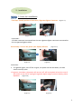
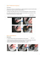
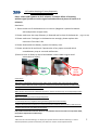
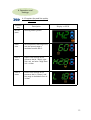
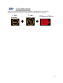
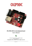
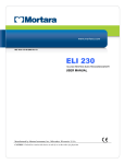
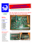
Head Up Display of Wireless Tire
Pressure Detector
User Manual
0
Table of content
1. Before Use
1.1 Introduction of Product Safety
1.2 Check Accessories
1.3 Introduction of Product Function
2.Method of Installation
2.1 HUD of Installation
2.2 Sensor Installation
2.3 Troubleshooting for Installation
3.Installation Accomplishment
3.1 Wireless Signal Reception
4. Operation and Set-up
4.1 Function Key and Set-up Key Operation
4.2 Warnings and Legends
4.3 Tire Status Check-up
5.Electric Utensil Regulation
5.1 Head Up Display
5.2 Sensor
1
1 . Before Use
1.1Introduction of Product Safety
Head Up Display of Wireless Tire Pressure Detector (HUD) is security gear in of wireless
detection of tire pressure. It can project all critical information such battery and temperature,
pressure specified in every tire and voltage of battery on the front windshield, which reminds
drivers of being alert to the information about the travel and status of tire , so as to reduce
down incidence rate of break down and safety issues.
While any abnormal condition is detected, the value in the voices/lights issued a warning to
drivers attention.
1.2 ssories List :
Parts
Quantity
HUD Host Unit
Power Cable
(USB/cigarette lighter
Connector )
Reflective Film
1
Velcro Tape
2
Sensor
4
CR1632, Battery
4
Anti-theft Nut
4
Wrench
1
User Manual
1
1
1
1.3 Introduction of Product Function
Power switch
Photosensitive
Test Area
Power connector
Function Key
Set-up Key
2
1.3.1 Function Key
Press [Function key] under normal mode to display settings in a cycle.
1.3.2 Set-up Key
Move to the function mode desired with [Function Button] and
press [Set-up Button] to reset; press [Function Button] to exit
settings once accomplishment.
Function
Key
Set-up
Key
Battery (VOLT)
Tire Pressure
Display
Tire Temperature Upper Limits settings
Tire Temperature
Display
Tire Pressure lower Limits Settings
Tire Pressure Bottom Limits Settings
Battery Voltage
Display
3
2. . Installation
2.1 Host Unit Installation
First Step : Search position of Host Unit / Cigarette lighter Connector (Figure I -2 )
( Figure I )
( Figure 2 )
Instruction :
1.Circular connector connected host the rear cigarette lighter connector connected to
the car cigarette lighter socket.
Second Step : Turn on the power ,the display will start
(Figure 3 )
( Figure 3-4 )
( Figure 4 )
Instruction :
1. If Cigarette lighter, turn off the engine, the power will be shut down, the host
switch normally open.
If engine is shut down, the power will not turn off will be required to host the rear of
the switch to turn off or unplug the cigarette lighter plug to prevent battery power
depletion. (Figure 5-6 )
(Figure 5 )
(Figure 6 )
4
Step 3 : Stick the Velcro Tape
Instruction :
1 . Stick the velcro tape at bottom side of host unit, then tear off the release film at
bottom layer and place it on the site driver wants to project. ( Figure 7/8/9 )
(Figure 7 )
( Figure 8 )
(Figure 9 )
Step 4 : Stick the Reflective Film
Instruction :
1. Wipe the site a reflective film is desired to stick with clean wiper. ( Figure 10 )
2. . Tear off the release film at the reverse side of reflective film and spray a little bit of
neutral soap water on glass projection area and reflective film surface. ( Figure 11-12 )
3. . Stick the reflective film onto front windshield and align it appropriately. ( Figure13 )
4. Scratch out any drops of water between reflective film and glass with scratch board
(card) and wipe it with clean wiper. ( Figure 14-15 )
5. . HUD installation is in completion.
(Figure 10 )
(Figure 15 )
(Figure 11 )
(Figure 14 )
( Figure 12 )
(Figure 13 )
5
2.2 Sensor Installation
Step 1: Make sure four Sensor are pasted with tire position sticker
Instruction :
1. . Take 4 Sensor and make sure if stickers marking 4 different positions of tires
are pasted onto, R 1(Right Front)/R2(Right Rear)/L1(Left Front)/L2(Left Rear)
( Figure 16 )
LF(L1)
LR(L2)
RF(R1)
RR(R2)
(Figure 16 )
Step 2 : Install Battery of SENSOR
Instruction :
1. Put batteries and snaps into Sensor by sequence and fasten up the lid.
Precaution:
(Figure 17 )
1) Negative pore of the battery shall be at bottom side and positive pore at upper side; it will
discharge instantly and run out of power if in reverse placement.
2) Please fasten up the lid completely to avoid penetration of vapor.
( 圖 23 )
(Figure 17 )
6
Step 3 : Install Sensor on the Tire
Instruction :
Every piece of Sensor is identified by a unique ID Code (tire positioned with HUD),
and paste its label on the Sensor (LF(L1) RF(R1)..).
1. Remove the plastic gas nozzle on the tire first and fasten it up with anti-theft
nut; make sure Sensor’s tire position labels are matched in tires’ positions, then
install and fasten them on the gas nozzle.
(Figure 18-21 )
Precaution: please must fasten sensor and gas nozzle; it might have gas leakage if failed to do.
(Figure 18)
(Figure 19)
(Figure 21)
(Figure 20)
Step 4 : Sensor Fasten-up
Instruction:
1. . Swivel the anti-theft nut toward direction of the sensor.
(Figure 22)
2. Take the wrench to buckle anti-theft nut with one hand and seize sensor with
another hand to fasten up with each other inward.
(Figure 23- 24)
3. Check if Sensor has been installed and fastened correctly.
(Figure 22)
(Figure 23)
(Figure 24)
7
2.3 Trouble-shooting of issues frequently
happened during Installation
FAQ 1 : After HUD is power on for 5 minutes, it remains failure of receiving
wireless signal (unable to receive signal transmitted from 4 pieces of Sensor in 5
minutes).
Resolution
1 . Please make sure if the batteries are in reverse. (Negative is poured at bottom
side and positive at upper side)
2. Please make sure the snap of battery is fastened and in close of the batteries. (Figure 25-26)
3. Please make sure if voltages in the batteries are enough; please replace with
new ones if less than 2.6V.
4. Please disassemble the battery, replace the battery once.
5. Please swivel the lid and check if penetration of any vapor occurred which
caused battery snap or rust and malfunction.
(Please be sure to fasten up the lid and adhere it with rubber ring to avoid
penetration of vapor)
Battery
Snaps
are not
adhered.
Battery
Snaps
adhere.
(Figure 25)
(Figure 26)
Precautions:
The system is operated on wireless signal, under certain situation, the system may be unable to
receive or reduce down the wireless signal as a result of environment intervention, mistakes made
during operation and improper installation.
When the tire cannot receive updated RF signal in 5 minutes consecutively, its red legend light will be
on to warn drivers.
When any of following situation happened, please:
1. Drive away the car (it might be strong wireless signal intervention nearby)
2. Please check if battery of Sensor is running out (less than 2.6Volt); please replace it with new one.
3. Please contact with your dealer for assistance.
FAQ 2: What should I do when the Sensor is with problems caused from lack of tire position labels,
tire position duplication or labels drop?
Resolution:
1.We have done ID code settings on display and 4 pieces of Sensor while in delivery; in case of
aforesaid problems, please consult with your dealer for reset to avoid misplacements.
8
3.2 Wireless Signal Reception
Step
Description
1
Start the engine, power turned
on.
(For turn on the power switch,
open Host at the power switch)
Into the enter the receiving
state.
2
When the Host receives RF
signal from Sensor, the red
light on the tire will extinguish
one after one.
3
Received all RF signals from 4
pieces of Sensor.
TPMS is ready.
Display on HUD
9
4. Operation and
Settings
4.1 Function Key and Set-up Key
Operation
Function
Key
Description
Do not
press
Showing battery power
Press
once
Set temperature warning of tire,
and the limited range is
available from 60-100 °C
Press 2
times
Upper Limit settings of tire
pressure, Bar (H = High), rightclick can set value range from
2.8 ~ 4.2 Bar.
Press 3
times
Lower Limit settings of tire
pressure, Bar (L = Lower), and
the range is available from 1.8~
3.2 Bar.
Display on HUD
10
4.2 Warnings and Legends
Description
Display on the Host Unit
Tire Pressure Warning Legend
When the tire pressure is too low or too high,
every 10 seconds prompted two short
beeps for one minute and, at the same time
the tire pressure warning icon flashes.
Tire Temperature Warning Legend
When the tire temperature is too high,
prompted two beeps every 10 seconds, and
for one minute, Tire temperature alarm icon
flashes.
Insufficient electricity power of tire warning
Legend
When individual tire pressure is less than 2.6
Volt, the tire chartShown and the battery
icon flashes and prompts every 10 seconds
two short beeps for one minute and you can
press the set button to enter the battery
voltage, view the tire and replace with new
ones.
Please note:
When battery power of Sensor is less than 2.6 Volt,
Sensor will be unable to work which has influences on
RF signal reception. Please replace with new batteries
immediately.
11
4.3 Tire Status Check-up
Press [Set-up] key and it will show pressure, temperature of every tire,
electric power of battery in a sensor (every value delays at 5 seconds)
1. Tire
Pressure
2. Tire
Temperature
3. Voltages of Battery
12
5.Electric Utensil
Regulation
5.1 Head Up Display
Voltage in Work
9 ~ 16V
Electric Current in
Work
50~350mA
Temperature in
Work
-40~85 ℃
Temperature in
Storage
-40~125 ℃
Frequency
433.92MHz
5.2 Sensor
Voltage in Work
3V
Temperature in
Work
-40~85 ℃
Temperature in
Storage
-40~85 ℃
Battery Range in
Detection
2.5V ~ 3.3V
Battery Life
1 ~ 2 Years
Frequency
433.92MHz
13