1
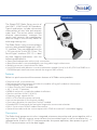
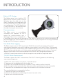
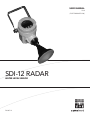
USER MANUAL
V2.0
(FOR FIRMWARE V2.0)
SDI-12 RADAR
WATER LEVEL SENSOR
D36 0514
CONTENTS & WARRANTY
Warranty.................................................................................1
Chapter 1: Introduction.......................................................2
Features................................................................................ 3
Built-in LCD Display............................................................ 4
Communications................................................................. 4
Fast Mode Data Logging....................................................4
“NOAA” Mode measurement............................................ 4
Fast Measure Mode............................................................ 5
FCC Approval...................................................................... 5
Chapter 2: Installation & Maintenance............................6
Installation Techniques....................................................... 7
General Installation Recommendations........................... 8
Mounting the Radar Unit - Vertical Alignment................ 8
Making Connections.......................................................... 9
Grounding Your Radar....................................................... 9
Over Cable..................................................................... 9
Wireless Radio.............................................................. 11
Connecting Your Data Logger.........................................12
Programming Your SDI-12 Data Recorder..................... 13
Programming the SDI-12 Interface................................. 13
Setup and Test Procedure............................................... 13
Programming the Radar Sensor...................................... 14
Built-in LCD Display.......................................................... 15
Chapter 3: SDI-12 Command & Response Protocol...17
Command Summary.........................................................19
Measure Command.......................................................... 19
“aM1” (NOAA) Measure Command............................... 21
“aM2” 1 Minute Average Measure Command.............. 23
“aM3” 15 Second Average Measure Command........... 24
Concurrent Measurement Command............................ 25
Concurrent “aC1!” Command......................................... 26
Concurrent “aC2!” Command......................................... 26
Send Data Command...................................................... 27
Measurements with CRC................................................. 28
Continuous Measurements............................................. 28
Send Acknowledge Command...................................... 28
Initiate Verify Command.................................................. 28
Send Identification Command........................................ 29
Change Sensor Address Command.............................. 30
Extended Set_Current_Stage Command...................... 31
Extended Read/Write Stage_Offset and Stage_Slope.31
Extended Read Number_of_Measurements................. 33
Extended Write Number_of_Measurements................ 33
Extended “XTEST”............................................................. 34
Chapter 4: Appendix.........................................................35
Appendix A: Specifications............................................. 36
Appendix B: FCC Equipment Authorization................. 37
Contents & Warranty
“WATERLOG™ PRODUCTS MANUFACTURED BY YELLOW SPRINGS INSTRUMENTS CO., INC.
are warranted by Yellow Springs Instruments Co., Inc. (“YSI”) to be free from defects in materials
and workmanship under normal use and service for twelve (12) months from date of shipment
unlessotherwise specified in the corresponding YSI pricelist or product manual.
WaterLOG™ products not manufactured, but that are re-sold by YSI, are warranted only to the
limits extended by the original manufacturer. Batteries, desiccant, and other consumables have
no warranty. YSI’s obligation under this warranty is limited to repairing or replacing (YSI’s option)
defective products,which shall be the sole and exclusive remedy under this warranty.
The customer shall assume all costs of removing, reinstalling, and shipping defective products to YSI.
YSI will return such products by surface carrier prepaid within the continental United States of America.
To all other locations, YSI will return such products best way CIP (Port of Entry) INCOTERM® 2010,
prepaid. This warranty shall not apply to any products which have been subjected to modification,
misuse, neglect, improper service, accidents of nature, or shipping damage. This warranty is in lieu
of all other warranties, expressed or implied. The warranty for installation services performed by YSI
such as programming to customer specifications, electrical connections to products manufactured by
YSI, and product specific training, is part of YSI’s product warranty. YSI EXPRESSLY DISCLAIMS AND
EXCLUDES ANY IMPLIED WARRANTIES OF MERCHANTABILITY OR FITNESS FOR A PARTICULAR
PURPOSE. YSI is not liable for any special, indirect, incidental, and/or consequential damages.”
A complete TERMS AND CONDITIONS OF SALE can be viewed at:
http://www.ysi.com/terms-and-conditions.php
This user manual is a guide for the H-3611/12/13 Radar Level Series. For more information, updated
manuals, brochures, technical notes, and supporting software on the H-3611/12/13 Radar, please
refer to waterlog.com/radar or contact your sales representative.
For additional assistance, please contact us at +1.435.753.2212 or [email protected]
1
01 /
2
INTRODUCTION
Introduction
The WaterLOG® Radar Series consist of
the H-3611, H-3612 and H-3613 products.
Typical applications include non-contact
measurement of river, lake and reservoir
water level. The sensor makes multiple
distance measurements, averages the
results and converts the measurement
data into Stage in units of Feet, Meters or
other engineering units.
The Radar Series is easy to use and works
with any data recorder/logger with a SDI12 interface. They are powered from the
+12V wire of the 3-wire SDI-12 bus. The
Serial-Digital Interface (SDI-12) is ideal
for data logging applications with the
following requirements:
• Battery powered operation with minimal current drain
• Measurement data is transmitted digitally over long cable lengths without error
• Multiple sensors on a simple three-wire cable
• Up to 250 feet of cable between a sensor and the data recorder (Use of an H-423, SDI-12 to RS485 or an
H-4500 fiberoptic media converter extends the range to 1000’s of feet)
Features
Below is a quick overview of the common features of all Radar series products.
• Simple to install, use, and maintain
• Non-contact level measurement eliminates the need for stilling wells and other infrastructure.
• Undamaged by ice, logs or debris
• ±3.0mm accuracy with standard model
• -40 ° C to +80 ° C operation
• NEMA 4x enclosure is suitable for outdoor installations
• Stainless steel horn (H-3611/ H-3612)
• Frequency range - approx 26 Ghz
• Built-in LCD screen for monitor and setup
• Low current operation (8.0 mA typical standby)
• Continuous operation, no warmup or “lock on” needed
• Extended SDI-12 commands for setting the Stage to the current water elevation.
• Built in 3 or 6 minute “NOAA” mode measurements.
• Optional fast mode sends the service request within 55mS for sustained 1-second data logging.
Description
The Radar Level gauge consists of an integrated microwave transmitter and sensor together with a
horn antenna. The horn antenna serves to focus the transmitted signal as well as to receive the 3
reflected echo. A built-in SDI-12 interface provides low power operation, data processing and
SDI-12 communications with the data logger.
INTRODUCTION
Built-in LCD Display
The Radar sensor has a built-in LCD
display which normally shows Distance
(distance from the radar unit to the
water). The display has three buttons and
can be used to monitor or edit the radar
unit configuration. The LCD display has
a short cord and can be detached from
the radar housing for convenience.
Communications
The Radar sensor is a stand-alone
instrument that provides an SDI-12
output for communications with a
datalogger. The sensor is supplied with
a liquid-tight fitting and two 6- foot cables. One cable is convenient for making connections to
your data logger, the second cable used to connect to a laptop computer when using the TofTool
configuration and diagnostic program.
Fast Mode Data Logging
The Radar response to an “aM!” command is “0044” (4-seconds, 4-parameters). The actual
measurement completes very quickly and the service request is sent within 530ms. The reported
4-second value allows time for retries when troubleshooting the internal connection between the
SDI-12 interface and the radar unit. Unfortunately most data loggers cannot sustain a 1-second
logging interval even if the sensor responds within 500mS. For making measurements at a
sustained 1-second measurement interval two options are available as explained below.
“NOAA” Mode Measurement
The Radar supports the “aM1” measurement. The H-3611 internally performs the following
measurement sequence.
1. Makes 181 measurements at a precise 1 second interval.
2. Computes the standard deviation for the data set.
3. Multiplies the standard deviation by 3 to obtain a High and Low outlier threshold.
4. Sifts through the data set and discards data points above and below the outlier thresholds.
5. Computes the standard deviation again for the data set with the outliers removed.
The standard deviation is computed as follows:
1. Compute the mean for the data set
2. Compute the deviation by subtracting the mean from each value
3. Square each individual deviation
4
Introduction
4. Divide by one less than the sample size
5. Take the square root
The “aM1” command response is “01844” (184 seconds, 4- parameters). The sensor buffer will
contain 4 parameters; mean, standard deviation, number of outliers and battery voltage.
If the built in “NOAA” mode is not workable, the H-3611 supports an alternate “fast measure”
mode.
Fast Measure Mode
Normally, the Radar transmits the service request within 530mS of receipt of the command. As
with many data loggers, this leaves insufficient time to sustain continuous measurements once
per second. The Power_Mode is an internal setting which places the H-3611 in a fast measure
mode. In this mode, the Radar is always awake and automatically collecting data from the
radar unit at a 1-second interval and stores the previous six minutes of data in the stack. In this
mode the sensor uses additional power. When an “aM!” measurement is received, the sensor
response is “0014” (1-seconds, 4-parameters). The service request is sent within 55mS of receipt
of the command (170mS of receipt of the break). This leaves plenty of time for a data logger to
collect the data while sustaining a 1-second logging interval. The data placed in the sensor buffer
is the results of the previous internal measurement (1-second old). The data logger must
implement its own internal NOAA or other filtering and averaging computations.
When in fast measure mode the radar makes continuous measurements which allows a different
type of NOAA mode measurement to take place. When in fast measure mode the “aM1!”
command is replaced with a command that takes the data from the previous six minutes and
performs the same procedure as the NOAA mode measurements, namely:
1. Collect a set of 1-Hz samples centered in the previous six minute time block, the
length of which is selected by the user (ranging from 1-360)
2. Computes the standard deviation for the data set.
3. Multiplies the standard deviation by 3 to obtain a High and Low outlier threshold.
4. Sifts through the data set and discards data points above and below the outlier thresholds.
5. Computes the mean and standard deviation again for the data set with the outliers removed.
In addition to the “aM1!” command, the “aM2!” and “aM3!” commands have been added which
take the simple average and standard deviation of the previous 1 minute and 15 second data sets
respectively. All of these commands have concurrent counterparts as well.
FCC Approval
This device complies with part 15 of the FCC Rules. Operation is subject to the following two
conditions: (1) This device may not cause harmful interference, and (2) this device must accept
any interference received, including interference that may cause undesired operation.
5
02 /
6
INSTALLATION
& MAINTENANCE
Installation & Maintenance
The Radar is a time-of-flight microwave radar level sensor. It excels in applications where ice, logs,
floating debris and boat traffic can damage stilling wells and other infrastructure. When installed
on a bridge over shallow streams having sandy bottoms the radar can be moved from location to
location as the river shifts channel position after storm events.
Installation Techniques
For installations where vandalism is of concern or additional protection is needed, many users
prefer to install the radar unit in a protective housing. The housing provides a convenient location
for installing other gauge station equipment such as a battery or data logger. Several housings
are available from WaterLOG, please contact the factory for further information. WaterLOG also
offers optional installation packages that have a solar panel, battery and short range
telemetry radio for communicating with a nearby gauge station.
Several typical installations are shown below.
7
INSTALLATION & MAINTENANCE
General Installation Recommendations
Before proceeding with the installation, please consider several site preparation and maintenance
issues. The Radar Series has been designed to operate safely in accordance with current technical,
safety and EU standards. Personnel must be authorised and suitably qualified. The manual must
have been read and understood, and the instructions followed.
Warning: Working over water or on tall structures can be dangerous. Use a safety harness,
fall arrest device, life saver and/or other safety equipment when conditions warrant.
Follow these guidelines when selecting a location for the radar gauge:
• The radar unit is a precision instrument and should not be jarred or dropped.
• The sensor must be mounted rigidly to prevent movement from wind and vibration.
• The antenna horn must be aligned within 1 ° of vertical to prevent trigonometric measurement errors.
• Make certain the sensor is mounted high enough to avoid being submerged during high water or flood
conditions.
• The sensor is rated NEMA 4x and can be mounted outdoors in unprotected locations.
• The operating temperature range for the sensor is –40 ° C to 80 ° C.
• The sensor should be mounted above the smoothest portion of the water surface. Generally between piers
of a bridge structure. However on bridges with long spans between the piers there will be more vibration
on the bridge. To moderate the vibration in these situations mount the radar 1/4 to 1/3 the span distance
from the pier.
• There should be a clear path between the sensor and the water to avoid false reflections. Try to locate the
sensor to keep the beam path (8 ° for 4-inch horn, 10 ° for 3-inch horn) clear of excessive turbulence,
splashing, waves, pipes, wires and other obstructions.
• Avoid submerged obstructions such as rocks or bridge piers that disturb or distort the water level.
• The mounting location should also avoid horizontal structural surfaces such as beams, brackets, and side
wall joints because these surfaces tend to reflect a strong false signal. If these cannot be avoided the display
can be used to map the radar beam profile and optimize the profile by means of electronic suppression of
interference echoes.
• Be aware that bridges and other large structures expand and contract with temperature. The bridge height
can change a few inches with diurnal temperature changes. Trucks and other traffic loads can cause transient
changes to the bridge height.
Mounting the Radar Unit - Vertical Alignment
Make certain the horn antenna is aligned within 1 ° of vertical. If the antenna is not vertical a
trigonometric measurement error with respect to the water will occur and the maximum range will
be reduced due to the off-axis return signal.
8
Installation & Maintenance
Making Connections
Since the Radar can be exposed to the
sun and weather, a cable rated for water
immersion (rain) and sunlight resistance
is required. A polyurethane or similar
sunlight and waterproof rated cable is
recommended. Do not use utility PVC
or other wiring materials which can
become brittle or crack when exposed to
ultraviolet radiation from the sun.
Liquid Tight Fitting
SDI-12 Connections
If conduit is used to connect to the Radar,
remove and discard the liquid-tight cord
retainer. If metal conduit is used, the
conduit must be grounded. When using
conduit the entry must be sealed with
silicone or other sealant to prevent moisture from entering the Radar enclosure via the conduit piping.
The thermal mass of the casting will cause water vapor to internally condense and accumulate with
changes in the weather.
Caution: Remove all power from the unit before making any connections.
Warning: All wiring must be done by qualified individuals in accordance with applicable
codes such as the ANSI/NFPA 70 specifications or the
Canadian Electrical Code Part 1.
Grounding Your Radar
The following graphic illustrations are the recommended methods for grounding the Radar. These
grounding methods will work if the guidelines are strictly followed. It should be mentioned that not
much can protect your site if it suffers a direct lightning strike. However, these general grounding
techniques can certainly help protect the equipment from normal occurrences. It is hoped that this
information will serve as a reference guide to grounding your Radar.
Grounding Your Radar Over Cable
Grounding the Radar is a simple yet subtle thing to do. Figures on page 10 show the preferred
methods for grounding a radar gauge over a cable. A metal conduit is to be used. If junction
boxes or pull boxes are used, they are to be metal as well. The metal conduit will provide a
conducting path to ground for the radar enclosure and also act as a shield that will conduct away
electrical noise. If a flex conduit is used at the radar enclosure or at the gauge house, this
conduit must be a conducting type of conduit. Note: you must also use a conducting
connector for conducting flex conduit. The electrical cable is to have a shield and at least 3
conductors. The wire conductor gauge of 20awg is recommended for most applications, but 9
you may certainly use 18 or 16 gauge conductors as well.
INSTALLATION & MAINTENANCE
Layout of Hard Wire Radar Installation
Layout of Hard Wire Radar Installation with Insulator
10
Installation & Maintenance
The main difference between the figures on page 10, is that the radar enclosure in the second
figure is insulated from the bridge structure. Typically bridges are constructed of steel and other
conducting materials which act as very good earth grounds. The insulator in this picture could be
the concrete you are mounting the radar to or some other nonconducting surface. You can also
choose to use a piece of nonconducting material to mount the radar to. Using this type of
installation, the same rules are followed for both. You must provide a metal conducting conduit
from the enclosure all the way back to the gauge house. No earth grounding is done at the radar.
All earth ground connections are made at the gauge house. Using these techniques will help
solve many of your grounding related issues.
Grounding Your Radar Using a Wireless Radio
This type of equipment installation by its nature is ideal, because the cabling that causes many of
the grounding problems has been removed. The cable has been replaced by a radio transmitter/
receiver pair. Thus there is no common powering or grounding required between these two
systems. All the equipment at the remote end or radar installation is connected to a local battery,
and there are no long cables and conduit to deal with or grounding issues that need to be
worked out. This type of installation electrically isolates the remote radar equipment from the
datalogger equipment. Thus, lightning and other electrical events will have little effect on this
type of installation.
Radio Bridge
11
INSTALLATION & MAINTENANCE
Remember that grounding should be simple. If your system grounding is getting complicated,
something is wrong. The purpose of grounding is to remove ground loops. Ground loops without
getting into a technical physics discussion, are the source of most equipment field failures. At the
gauge house, use a simple Single Point Ground as shown in the above illustrations. Remove any
multiple or redundant ground wires. Keep your wires neat and clean. Things that look good seem
to work good.
Connecting Your Data Logger
The Radar is supplied with a 6-foot, 4-conductor polyurethane cable for making convenient
connections to your data logger. The cable is routed thru a liquid tight cord connector on the radar
housing and is waterproof and sunlight resistant. The Radar is a SDI-12 V1.3 compliant sensor and
connects directly to any data recorder with SDI-12 capability.
4-Conductor Cable
Color
Function
Red
+12V Power
White
SDI-12 Data
Black
Gnd
Green
Gnd
If the 6-foot cable is unsuitable for your application it may be removed and replaced with a longer
cable. Internal to the radar housing, the SDI-12 interface module has a removable 3-position
connector for making the SDI-12 connections. The SDI-12 connections provides both +12V power
and SDI-12 serial data communications. You will need a 1/8 inch blade screwdriver to connect the
wires to the plug-in connector. The connections inside the radar housing may be accessed with the
following procedure:
1. Disconnect the power supply
2. Unscrew the housing cover (the round casting with the glass window). Do not contaminate
or dislodge the o-ring seal in the cover
3. Remove and unplug the LCD display module
4. Remove the cover plate from the terminal compartment
5. Disconnect the 3-position green connector
6. Loosen the nut on the liquid tight connector
7. Unseat (loosen) the rubber grommet in the liquid tight connector
8. Remove the existing 4-conductor cable
If your cable has a dedicated ground wire, connect it to the internal ground screw on the bracket
(the bracket is grounded to the enclosure).
12
NOTE: This device must not include, or make provisions for, the use of battery chargers which permit
operating while charging, AC adapters or battery eliminators and must not connect to the AC power lines
indirectly, obtaining power through another device.
Installation & Maintenance
Programming Your SDI-12 Data Recorder
You must prepare your data recorder to receive and record the Radar data. Since data recorders
differ widely, refer to your data recorder manufacturer’s directions. In general, program the data
recorder to input four values via the SDI-12 port. Usually only one or two of the parameters are
actually recorded. Your data recorder must issue an “aM!” command, then collect the data with a
“aD0” command, as explained in Chapter 3. The Radar places four parameters in its data buffer:
a+AA.AAA+BB.BBB+CC+DD.D<cr><lf>
Where:
a AA.AAA BB.BBB CC
DD.D = SDI-12 address 0-9, A-Z
= Stage (feet, inches, meters etc.)
= Distance (feet, i.e. raw radar measurement)
= Measurement Status (0 = success)
= Power Supply Voltage (Volts)
Programming The SDI-12 Interface
The radar unit measures the distance between the mounting flange of the horn to the water surface.
The SDI-12 interface (internal or external) processes the raw Distance measurement with a Stage
= m * Distance + b equation. The Slope (m) and Offset (b) terms are programmable, allowing the
user to scale the reading into other engineering units. The Radar comes from the factory with the
following settings:
SDI Address: 0
Slope: -1.0
Offset 0.0
With these values the Stage measurement data will be in units of feet. The reason for a negative
slope is that the radar measures Distance, as the water rises Distance decreases. These setups are
stored in FLASH memory within the Radar and will not be lost if the power is disconnected. The
extended commands for changing the address, slope and offset are described in detail in Chapter 3.
If more than one sensor is to be connected to the SDI-12 bus, make certain each sensor has a unique
address.
Setup and Test Procedure
Step 1:
Double check all wiring connections. Connect the Radar to your data recorder and apply +12V
power.
Step 2:
The Radar comes from the factory with it’s SDI-12 address set to “0”. Verify the Radar is responding
by issuing a “0I!” Send Identification command. If more than one sensor is to be connected to the
SDI-12 bus, make certain each sensor has a different sensor address. If needed, the address can
13
be changed with an SDI-12 command (see Chapter 3).
INSTALLATION & MAINTENANCE
Step 3:
Make several measurements (“aM!” and “aD0!”) and verify the Distance measurement is correct.
Do not be concerned if the Distance measurement is several inches in error, the radar sensor may
have a small distance offset and it’s often difficult to directly measure between the mount flange
and the water surface . The Distance value is continually displayed on the built-in LCD display.
Step 4:
With the Slope set to -1.0 the Stage will be in units of feet. If other engineering units are wanted
change the Slope as described in Chapter 3.
Step 5: Setting the Stage
When the Radar is first installed, you will want to adjust the Offset such that the SDI-12 measurement
data (Stage) corresponds to the current water elevation or stage as determined with a staff gauge
or other datum.
An extended SDI-12 command is convenient to quickly set the Radar Stage reading to match the
current water level. The “aXSCSdd.d!” command causes the Radar to make a fresh measurement and
automatically update the Offset as needed to produce the desired Stage. See Chapter 3 for details.
Example of a H-3611 Extended “Set Current Stage” command:
Command Response Time Values Description
“aXSCS2.3!” “a0041<cr><lf>” 4sec 1 Set the Stage to 2.3
Subsequent Command Response Description
“aD0” a+12.80<cr><lf> The new Offset
Step 6:
Make several measurements and make certain the Stage reading is correct and the measurements
are stable for the current water level and conditions.
If available, a H-4191 SDI-12 to RS-232 interface can be used to observe the “XTEST” mode.
The “XTEST” mode causes the Radar to transmit unsolicited real-time data for testing purposes. The
test mode is used to help troubleshoot the installation by providing a continuous readout of sensor
data. This is not compliant with the SDI-12 specification and is not used with data loggers.
Programming the Radar Sensor
The radar unit has many setups and configurations including measurement units, max/min distance,
averaging and media conditions. For most users the Radar comes from the factory pre-configured
for most hydrological applications and can be used “out of the box”. For special applications and
when performing maintenance and diagnostics the radar unit configuration can be monitored and
changed by either the built-in LCD display or a Windows™ based PC program called TofTool (TimeOf-Flight-Tool)
14
Installation & Maintenance
Built-in LCD Display
The built-in LCD display normally displays
Distance (distance from the radar unit to
the water). The display has three buttons
and can be used to monitor and edit the
radar unit configuration. To access the
display, unscrew the housing cover (the
round casting with the glass window).
Take precautions to not contaminate or
dislodge the o-ring seal in the cover. The
LCD display has a short cord and can be
detached from the radar for convenience.
Each function menu has a Function Group
and Function number in the upper right
hand corner of the screen. Together they
provide orientation within the menu map.
15
INSTALLATION & MAINTENANCE
The radar unit supports other configurations such as tank volume gauging which are not used for
stream gauging applications. When using the LCD setup menus, be careful to not indiscriminately
alter the setup parameters. For special applications or problematic installations such as having false
echoes from a bridge pier please contact WaterLOG for advice.
16
03 /
SDI-12 COMMAND &
RESPONSE PROTOCOL
17
SDI-12 COMMAND & RESPONSE
This is a brief description of the Serial Digital Interface (SDI-12) Command and Response Protocol
used by the WaterLOG® Radar Series. Included is a description of the commands and data format
supported by the Radar.
Refer to the document "A SERIAL DIGITAL INTERFACE STANDARD FOR HYDROLOGIC AND
ENVIRONMENTAL SENSORS". Version 1.3 January 12, 2009 Coordinated by the SDI-12 Support
Group, 135 East Center, Logan, Utah.
During normal communication, the data recorder sends an address together with a command to
the Radar SDI-12 sensor. The Radar then replies with a "response." In the following descriptions,
SDI-12 commands and responses are enclosed in quotes. The SDI-12 address and the command/
response terminators are defined as follows:
“a” Is the sensor address. The following ASCII Characters are valid addresses:
“0-9”, “A-Z”, “a-z”, “*”, “?”. Sensors will be initially programmed at the factory with the address of “0” for use in single sensor systems. Addresses “1 to 9” and “A to Z” or “a to z” can be used for additional sensors connected to the same SDI-12
bus. Address “*” and “?” are “wild card” addresses which select any sensor, regardless of its actual address.
Is the last character of a command block.
“!” “<cr><lf>” Are carriage return (0D) hex and line feed (0A) hex characters. They are the last two characters of a response block.
Notes:
• All commands/responses are upper-case printable ASCII characters.
• Commands must be terminated with a “!” character.
• Responses are terminated with <cr><lf> characters.
• The command string must be transmitted in a contiguous block with no gaps of more than 1.66 milliseconds
between characters.
To enhance the error detection capability in SDI-12 data collection systems, a variation of the Start
Measurement Commands (M!, M1! ... M9!), Start Concurrent Measurement Commands (C!, C1! ...
C9!), and Continuous Measurement Commands (aR0! ... aR9!) request that the data be returned
with a 16 bit Cyclic Redundancy Check (CRC) appended to it. These commands use the existing
command letters with a C appended, namely: aMC!, aMC1! ... aMC9!, aCC!, aCC1! ... aCC9!, and
aRC0! ... aRC9!. When these commands are used, the data returned in response to the D commands,
or R commands, have a CRC code appended to it.
18
SDI-12 Command & Response
Command Summary
The Radar supports the following SDI-12 commands:
Standard Commands:
aM! Make measurement
aM1! Make NOAA measurement
aM2! Make 1 minute average measurement
aM3! Make 15 second average measurement
aD0! Send Data
aV! Verify
aI! Send Identification
a! Send Acknowledge
aAn! Change Address
Extended Commands:
aXRS! Read Slope
aXWSnn! Write Slope
aXRO! Read Offset
aXWOnn! Write Offset
aXRPM! Read Power Mode (0=Sleep, 1=Fast Measure)
aXWPMn! Write Power Mode (0=Sleep, 1=Fast Measure)
aXWNM! Write the number of measurements used in the fast mode “aM1” command
aXRNM! Read the number of measurements used in the fast mode “aM1” command
aXTEST! Displays the current settings, then displays data at a fast rate
aXHELP! Displays the supported commands
Measure Command
The Measure Command causes a measurement sequence to be performed. Data values generated
in response to this command are stored in the sensor’s buffer for subsequent collection using “D”
commands. The data will be retained in the sensor until another “M”, “ C”, or “V” command is
executed.
Command “aM!” Response “atttn<cr><lf>” Description
Initiate measurement
Where:
a
is the sensor address (“0-9”, “A-Z”, “a-z”, “*”, “?”).
is an upper-case ASCII character
M
ttt is a three digit integer (000-999) specifying the maximum time, in seconds, the sensor will take to complete the command and have measurement data available in its buffer.
n
is a single digit integer (0-9) specifying the number of values that will be placed in the data buffer. If “n” is zero (0), no data will be available using subsequent “D”
commands.
19
SDI-12 COMMAND & RESPONSE
Upon completion of the measurement, a service request “a<cr><lf>” is sent to the data recorder
indicating the sensor data is ready. The data recorder may wake the sensor with a break and collect
the data any time after the service request is received or the specified processing time has elapsed.
Example of an "aM!" command:
Command "aM!" Response Time "a0044<cr><lf>" 4 sec Values 4 Description
Make measurement
Note: The service request is normally sent within 530mS of receipt of the break.
Subsequent Command Response
"aD0" a+AA.AAA+BB.BBB+CC+DD.D<cr><lf>
Where:
AA.AAA
= Stage (feet, inches, meters etc.)
BB.BBB
= Distance (feet)
CC = Measurement Status:
0 = No errors
1 = 500ms response timeout
2 = Response overflowed the buffer
3 = No preamble FF's
4 = Missing start byte (delimiter)
5 = Wrong delimiter
6 = Wrong command byte
7 = Response code not zero
8 = Field Device Malfunction (Device Status = $80)
9 = Wrong byte count byte
10 = Not enough bytes received
11 = Frame parity error
DD.D = Power Supply Voltage (Volts)
Each SDI-12 data point or “measurement” is input from the radar subsystem. The “aM!” command
does not filter or average the measurement data. The radar unit internally processes raw distance
measurements with a damping factor and other filtering algorithms.
20
SDI-12 Command & Response
“aM1” (NOAA) Measure Command
The Radar supports two different “aM1” measurement commands based on the Power Mode.
Data values generated in response to this command are stored in the sensor’s buffer for subsequent
collection using “D” commands. The data will be retained in the sensor until another “M”, “ C”,
or “V” command is executed.
When Power Mode = 0, the Radar internally performs the following measurement sequence:
1. Makes 181 measurements at a precise1.0 second interval.
2. Computes the standard deviation for the data set.
3. Multiplies the standard deviation by 3 to obtain a High and Low outlier threshold.
4. Sifts through the data set and discards data points above and below the outlier thresholds.
5. Computes the mean and standard deviation again for the data set with the outliers removed.
When Power Mode = 1, the Radar internally performs the following measurement sequence:
1. Collect a set of 1-Hz samples centered in the previous six minute time block, the length of
which is selected by the user (ranging from 1-360 data points)
2. Computes the standard deviation for the data set.
3. Multiplies the standard deviation by 3 to obtain a High and Low outlier threshold.
4. Sifts through the data set and discards data points above and below the outlier thresholds.
5. Computes the mean and standard deviation again for the data set with the outliers removed.
The standard deviation is computed as follows:
1. Compute the mean for the data set
2. Compute the deviation by subtracting the mean from each value
3. Square each individual deviation
4. Divide by one less than the sample size
5. Take the square root
Command “aM1!” Where:
a
M
ttt n
Response “atttn<cr><lf>” Description
Initiate measurement
is the sensor address (“0-9”, “A-Z”, “a-z”, “*”, “?”).
is an upper-case ASCII character
is a three digit integer (000-999) specifying the maximum time, in seconds, the sensor will take to complete the command and have measurement data available in its buffer.
is a single digit integer (0-9) specifying the number of values that will be placed in the data buffer. If “n” is zero (0), no data will be available using subsequent “D” commands.
21
SDI-12 COMMAND & RESPONSE
Upon completion of the measurement, a service request “a<cr><lf>” is sent to the data recorder
indicating the sensor data is ready. The data recorder may wake the sensor with a break and collect
the data any time after the service request is received or the specified processing time has elapsed.
Example of an "aM1!" command when Power Mode = 0:
Command "aM1!" Response Time "a1844<cr><lf>" 184 sec Values 4
Description
Make measurement
Note: The service request is normally sent within 182 seconds of receipt of the command. The
184-second value reported allows time for a few retries when communicating with the radar
subsystem.
Subsequent Command Response
"aD0" a+AA.AAA+BB.BBB+CC+DD.D<cr><lf>
Where:
AA.AAA BB.BBB CC DD.D = Stage (feet, inches, meters etc.)
= Standard Deviation (feet, inches, meters etc.)
= Number of outlier data points discarded
= Power Supply Voltage (Volts)
Example of an “aM1!” command when Power Mode = 1:
Command "aM1!" Response Time “a0014<cr><lf>” 1 sec
Values 4
Description
Make measurement.
Subsequent Command Response
"aD0" a+AA.AAA+BB.BBB+CC+DD.D<cr><lf>
Where:
AA.AAA BB.BBB CC DD.D 22
= Stage (feet, inches, meters etc.)
= Standard Deviation (feet, inches, meters etc.)
= Number of outlier data points discarded
= Power Supply Voltage (Volts)
SDI-12 Command & Response
“aM2” 1 Minute Average Measure Command
The Radar only supports the”aM2” measurement command when the Power Mode = 1. Data
values generated in response to this command are stored in the sensor’s buffer for subsequent
collection using “D” commands. The data will be retained in the sensor until another “M”, “ C”,
or “V” command is executed.
When Power Mode = 0, the Radar returns “a0000” signifying the command is not supported in
this mode.
When Power Mode = 1, the H-3611 averages the data collected from the previous minute and
returns the mean and standard deviation
.
The standard deviation is computed as follows:
1. Compute the mean for the data set
2. Compute the deviation by subtracting the mean from each value
3. Square each individual deviation
4. Divide by one less than the sample size
5. Take the square root
Command “aM1!” Where:
a
M
ttt n
Response “atttn<cr><lf>” Description
Initiate measurement
is the sensor address (“0-9”, “A-Z”, “a-z”, “*”, “?”).
is an upper-case ASCII character
is a three digit integer (000-999) specifying the maximum time, in seconds, the sensor will take to complete the command and have measurement data available in its buffer.
is a single digit integer (0-9) specifying the number of values that will be placed in the data buffer. If “n” is zero (0), no data will be available using subsequent “D” commands.
Upon completion of the measurement, a service request “a<cr><lf>” is sent to the data recorder
indicating the sensor data is ready. The data recorder may wake the sensor with a break and collect
the data any time after the service request is received or the specified processing time has elapsed.
23
SDI-12 COMMAND & RESPONSE
Example of an “aM2!” command:
Command "aM2!" Response Time “a0013<cr><lf>” 1 sec
Values 3
Description
Make measurement.
Subsequent Command Response
"aD0" a+AA.AAA+BB.BBB+CC.C<cr><lf>
Where:
AA.AAA BB.BBB CC.C = Stage (feet, inches, meters etc.)
= Standard Deviation (feet, inches, meters etc.)
= Power Supply Voltage (Volts)
“aM3” 15 Second Average Measure Command
The Radar only supports the”aM3” measurement command when the Power Mode = 1. Data
values generated in response to this command are stored in the sensor’s buffer for subsequent
collection using “D” commands. The data will be retained in the sensor until another “M”, “ C”, or “V”
command is executed.
When Power Mode = 0, the Radar returns “a0000” signifying the command is not supported in this
mode.
When Power Mode = 1, the Radar averages the data collected from the previous fifteen seconds
and returns the mean and standard deviation
The standard deviation is computed as follows:
1. Compute the mean for the data set
2. Compute the deviation by subtracting the mean from each value
3. Square each individual deviation
4. Divide by one less than the sample size
5. Take the square root
Command “aM3!” Where:
a
M
ttt n
24
Response “atttn<cr><lf>” Description
Initiate measurement
is the sensor address (“0-9”, “A-Z”, “a-z”, “*”, “?”).
is an upper-case ASCII character
is a three digit integer (000-999) specifying the maximum time, in seconds, the sensor will take to complete the command and have measurement data available in its buffer.
is a single digit integer (0-9) specifying the number of values that will be placed in the data buffer. If “n” is zero (0), no data will be available using subsequent “D” commands.
SDI-12 Command & Response
Upon completion of the measurement, a service request “a<cr><lf>” is sent to the data recorder
indicating the sensor data is ready. The data recorder may wake the sensor with a break and collect
the data any time after the service request is received or the specified processing time has elapsed.
Example of an “aM3!” command:
Command "aM3!" Response Time “a0013<cr><lf>” 1 sec
Values 3
Description
Make measurement.
Subsequent Command Response
"aD0" a+AA.AAA+BB.BBB+CC.C<cr><lf>
Where:
AA.AAA BB.BBB CC.C = Stage (feet, inches, meters etc.)
= Standard Deviation (feet, inches, meters etc.)
= Power Supply Voltage (Volts)
Concurrent Measurement Command
A concurrent measurement is one which occurs while other SDI-12 sensors on the bus are also
taking measurements. This command is similar to the “aM!” command, however, the nn field has
an extra digit and the sensor does not issue a service request when it has completed the
measurement. Communicating with other sensors will NOT abort a concurrent measurement.
Data values generated in response to this command are stored in the sensor’s buffer for subsequent
collection using “D” commands. The data will be retained in the sensor until another “M”, “C”, or
“V” command is executed.
Command “aC!” Where:
a
C
ttt nn Response “atttnn<cr><lf>” Description
Initiate measurement
is the sensor address (“0-9”, “A-Z”, “a-z”, “*”, “?”).
is an upper-case ASCII character
is a three digit integer (000-999) specifying the maximum time, in seconds, the sensor will take to complete the command and have measurement data available in its buffer.
is a two digit integer (00-99) specifying the number of values that will be placed in the
data buffer. If “n” is zero (0), no data will be available using subsequent “D” commands.
The data recorder may wake the sensor with a break and collect the data anytime after the specified
processing time has elapsed.
25
SDI-12 COMMAND & RESPONSE
Concurrent “aC1!” Command
This command is similar to the “aM1!” command, however, the nn field has an extra digit and the
sensor does not issue a service request when it has completed the measurement. Data values
generated in response to this command are stored in the sensor’s buffer for subsequent collection
using “D” commands. The data will be retained in the sensor until another “M”, “C”, or “V”
command is executed.
Command “aC1!” Where:
a
C
ttt nn Response “atttnn<cr><lf>” Description
Initiate measurement
is the sensor address (“0-9”, “A-Z”, “a-z”, “*”, “?”).
is an upper-case ASCII character
is a three digit integer (000-999) specifying the maximum time, in seconds, the sensor will take to complete the command and have measurement data available in its buffer.
is a two digit integer (00-99) specifying the number of values that will be placed in the
data buffer. If “n” is zero (0), no data will be available using subsequent “D” commands.
The data recorder may wake the sensor with a break and collect the data anytime after the specified
processing time has elapsed. This command may not work for some applications, as the data logger
must wait 1 second before collecting data, which may not work for applications requiring a faster
response.
Concurrent “aC2!” Command
This command is similar to the “aM2!” command, however, the nn field has an extra digit and the
sensor does not issue a service request when it has completed the measurement. Data values
generated in response to this command are stored in the sensor’s buffer for subsequent collection
using “D” commands. The data will be retained in the sensor until another “M”, “C”, or “V” command
is executed..
Command “aC2!” Where:
a
C
ttt 26
nn Response “atttnn<cr><lf>” Description
Initiate measurement
is the sensor address (“0-9”, “A-Z”, “a-z”, “*”, “?”).
is an upper-case ASCII character
is a three digit integer (000-999) specifying the maximum time, in seconds, the sensor will take to complete the command and have measurement data available in its buffer.
is a two digit integer (00-99) specifying the number of values that will be placed in the
data buffer. If “n” is zero (0), no data will be available using subsequent “D” commands.
SDI-12 Command & Response
The data recorder may wake the sensor with a break and collect the data anytime after the specified
processing time has elapsed.
Send Data Command
The Send Data command returns sensor data generated as the result of previous “aM!”, “aM1!”,
“aC!”, or “aV!” commands. Values returned will be sent in 33 characters or less. The sensor’s data
buffer will not be altered by this command.
Command “aD0!” through “aD9!” Where:
a D0...D9
p Response “apd.d ... pd.d<cr><lf>”
is the sensor address (“0-9”, “A-Z”, “a-z”, “*”, “?”).
areupper-case ASCII character
Is a polarity sign (+ or -)
d.d represents numeric digits before and/or after the decimal. A decimal may be used in any position in the value after the polarity sign. If a decimal is not used, it will be assumed to be after the last digit.
For example: +3.29 +23.5 -25.45 +300
If one or more values were specified and a “aD0!” returns no data (<CR><LF> only), it means that the
measurement was aborted and a new “M” command must be sent.
Example of an “aD0!” command:
Previous Command Response "aM!" “a0044<cr><lf>” Note: The service request is normally sent within 530mS of receipt of the break.. The 4-second
value reported allows time for a few retries when communicating with the radar subsystem.
Subsequent Command Response
"aD0" a+AA.AAA+BB.BBB+CC.C<cr><lf>
Where:
AA.AAA BB.BBB CC DD.D
= Stage (feet, inches, meters etc.)
= Distance (feet)
= Measurement Status
= Power Supply Voltage (Volts)
27
SDI-12 COMMAND & RESPONSE
Measurements with CRC
To enhance the error detection capability in SDI-12 data collection systems, a variation of the Start
Measurement Commands (M!, M1! ... M9!), Start Concurrent Measurement Commands (C!, C1! ...
C9!), and Continuous Measurement Commands (aR0! ... aR9!) request that the data be returned
with a 16 bit Cyclic Redundancy Check (CRC) appended to it. These commands use the existing
command letters with a C appended, namely: aMC!, aMC1! ... aMC9!, aCC!, aCC1! ... aCC9!, and
aRC0! ... aRC9!. When these commands are used, the data returned in response to the D commands,
or R commands, have a CRC code appended to it.
All Measure and Concurrent Measure Commands support the CRC functionality. In order to have
the CRC appended to the data of, for example, the “aM!” command the command would change
to “aMC!” The Concurrent Measurements also support the CRC, so for a CRC to be appended onto
the “aC1!” command, the variant would be “aCC1!”
Continuous Measurements
This is a command for the Version 1.2 SDI-12 Specification. Sensors that are able to continuously
monitor the phenomena to be measured, such as a cable position, do not require a start measurement
command. They can be read directly with the R commands (R0!...R9!). The R commands work exactly
like the D (D0!...D9!) commands. The only difference is that the R commands do not need to be
preceded with an M command.
The Radar does not support the aR0! continuous measurement commands because the measurement
and math operations require more than 10mS to complete.
Send Acknowledge Command
The Send Acknowledge Command returns a simple status response which includes the address of
the sensor. Any measurement data in the sensor’s buffer is not disturbed.
Command
Response
“a!”“a<cr><lf>”
Where:
a
Is the sensor address (“0-9”, “A-Z”, “a-z”, “*”, “?”).
Initiate Verify Command
The Verify Command causes a verify sequence to be performed. The result of this command is
similar to the “aM!” command except that the values generated are fixed test data and the results of
diagnostic checksum tests. The data generated in response to this command is placed in the sensor’s
buffer for subsequent collection using “D” commands. The data will be retained in the sensor until
another “M”, “C”, or “V” command is executed.
Command “aV!” 28
Response “atttn<cr><lf>” Description
Initiate verify sequence
SDI-12 Command & Response
Where:
a
is the sensor address (“0-9”, “A-Z”, “a-z”, “*”, “?”).
is an upper-case ASCII character.
V
ttt is a three digit integer (000-999) specifying the maximum time, in seconds, the sensor will take to complete the command and have data available in its buffer.
n
is a single digit integer (0-9) specifying the number of values that will be placed in the data buffer. If “n” is zero (0), no data will be available using subsequent “D” commands
Example of an “aV!” command:
Command Response Time
Values
Description
"aV!" “a0013<cr><lf>” 1 sec 3 Return fixed data and diagnostic data for testing purposes.
Subsequent Command Response
"aD0" a+123.456+78.9+y<cr><lf>
Key +123.456 +78.9 y Description Fixed test data
Fixed test data
ROM checksum test Units
0 = Failed, 1 = Passed
Send Identification Command
The Send Identification Command responds with sensor vendor, model, and version data. Any
measurement data in the sensor’s buffer is not disturbed.
Command Response
“aI!” “allccccccccmmmmmmvvvxx...xx<cr><lf>”
Where:
a I ll cccccccc is the sensor address (“0-9”, “A-Z”, “a-z”, “*”, “?”).
is an upper-case ASCII character.
is the SDI-12 version compatibility level, e.g. version 1.2 is represented as “12”.
is an 8 character vendor identification to be specified by the vendor and usually
in the form of a company name or its abbreviation.
mmmmmm is a 6 character field specifying the sensor model number.
vvv is a 3 character field specifying the sensor version number.
29
SDI-12 COMMAND & RESPONSE
xx...xx is an optional field of up to a maximum of 13 characters to be used for serial number
or other specific sensor information not relevant to operation of the data recorder.
Example of a “aI!” command:
“a12 DAA H-3611vvvS#nnnnnnVkkk<cr><lf>”
Radar implementation of the optional 13 character field:
S#nnnnnnVkkk (12 bytes total)
Where:
“nnnnnn
“kkk” is a six character sensor serial number
is a three digit sensor firmware revision level
Change Sensor Address Command
The Change Sensor Address Command allows the sensor address to be changed. The address is
stored in non-volatile EEPROM within the sensor. The Radar will not respond if the command was
invalid, the address was out of range, or the EEPROM programming operation failed.
Command “aAn! Response “n<cr><lf>” Description
Change sensor address
Where:
a
is the current (old) sensor address (“0-9”, “A-Z”, “a-z”, “*”, “?”). An ASCII “*” may be used as a “wild card” address if the current address is unknown and only one sensor is connected to the bus.
A
is an upper-case ASCII character.
n
is the new sensor address to be programmed (“0-9”, “A-Z”).
NOTE: To verify the new address use the “Identify Command.”
Example of a “Change Sensor Address” command:
Command Response Description
“aA2! “2<cr><lf>” Change sensor address to “2”
30
SDI-12 Command & Response
Extended Set_Current_Stage Command
The Radar processes Distance data and computes Stage = m * Distance + b. During installation it is
convenient to quickly set the Radar’s Stage reading to match the current stage or elevation of the
water as determined by a staff gauge or other datum. This command causes the Radar to make a
fresh measurement and automatically update the Offset (b) term as needed to produce the desired
Stage.
Example of an Extended “Set Current Stage” command:
Command “aXSCS2.3!” Response Time
“a0041<cr><lf>” 4 sec Subsequent Command
“aD0” Values
1 Description
Set the Stage to 2.3
Response Description
a+12.80<cr><lf> The new Offset
Extended Read/Write Stage_Offset and Read/Write Stage_Slope
The Radar processes the Distance data and computes Stage = m * Distance + b. The Slope (m) and
Offset (b) terms are programmable, allowing the user to scale the reading into other engineering
units. These commands allow the user to read or write (change) the Slope and Offset terms. The
Slope is set to -1.0 and the Offset to 0.00 at the factory. With the factory default (-1.0) the Stage will be
in units of water depth (in feet). The reason for a negative slope is that the radar measures Distance,
as the water rises Distance decreases. These values are stored in non-volatile FLASH memory within
the sensor. Once the new Slope or Offset value is written to the FLASH memory, a copy is sent to the
sensor data buffer for verification. This data can be viewed by using a subsequent “D” command. To
verify these settings any other time, use the “XRS” or “XRO” commands. This command takes 001
seconds to complete and places 1 value in the data buffer. Use the “aD0” command to collect and
view the new slope or offset.
Command “aXRS!”
“aXRO!” “aXWSddd!” “aXWOddd!” Response “a0011<cr><lf>” “a0011<cr><lf>” “a0011<cr><lf>” “a0011<cr><lf>” Description
Read Slope
Read Offset
Write Slope
Write Offset
Where:
a is the sensor address (“0-9”, “A-Z”, “a-z”, “*”, “?”)
XRS
are upper case characters
XRO are upper case characters
XWS
are upper case characters
XWO are upper case characters
ddd is the new slope or offset value (For example: 20.0, 195)
31
SDI-12 COMMAND & RESPONSE
Example of an Extended “Read Slope” command:
Command “aXRS!” Response Time
“a0011<cr><lf>” 1 sec Subsequent Command
“aD0!” Values
1 Description
Read Slope
Response Description
“a+1.00<cr><lf>” Slope is 1.00
Example of an Extended “Write Slope” command:
Command “aXWS1.234!” Response Time
“a0011<cr><lf>” 1 sec Subsequent Command
“aD0!” Values
1 Description
Write Slope
Response Description
“a+1.234<cr><lf>” Slope is 1.234
Extended Read Power_Mode and Write Power_Mode
Normally, the Radar transmits the service request within 530mS of receipt of the break. As with some
data loggers, this leaves insufficient time to sustain continuous measurements once per second.
The Power_Mode is an internal setting which puts the Radar in a fast measure mode. In this mode
the Radar is always awake and automatically collecting data from the radar unit and storing it at
1-second intervals. In this mode the sensor uses additional power. Changing this mode will allow
and disallow the use of some measurement types.
This command is used to change the power mode. The Radar comes from the factory with the power
mode set to the Sleep mode. This setting is stored in non-volatile FLASH memory within the sensor.
Once a new value is written, a copy is sent to the sensor data buffer for verification. This data can
be viewed by using a subsequent “D” command. To read or verify the value any other time, use the
“XRPM” command.
Command “aXRPM!” “aXWPMn!” Where:
a XRPM XWPM n
32
Response Description
“a0011<cr><lf>” Read Power_Mode
“a0011<cr><lf>” Write Power_Mode
is the sensor address (“0-9”, “A-Z”, “a-z”, “*”, “?”).
are upper case characters.
are upper case characters.
is the new setting (0 or 1)
0 = Sleep between measurements
1 = Make continuous measurements
SDI-12 Command & Response
This command takes 001 seconds to complete and places 1 value in the data buffer. Use the “aD0”
command to collect and view the current value.
Extended Read Number_of_Measurements and Write Number_of_Measurements
This command is used to change the number of measurements used in the “aM1!” command when
the Power Mode is set to 1. The Radar comes from the factory with the number of measurments set
to 360. This setting is stored in non-volatile FLASH memory within the sensor. The minimum and
maximum values that can be written are 1 and 360, respectively, anything beyond these values will
be set to one of the endpoints.
Once a new value is written, a copy is sent to the sensor data buffer for verification. This data can
be viewed by using a subsequent “D” command. To read or verify the value any other time, use the
“XRPM” command.
Command “aXRNM!” “aXWNMnn!” Response Description
“a0011<cr><lf>” Read Number_of_Measurements
“a0011<cr><lf>” Write Number_of_Measurements
Where:
a XRNM is the sensor address (“0-9”, “A-Z”, “a-z”, “*”, “?”).
XWNM are upper case characters.
nn is the new setting (1 - 360)
are upper case characters.
This command takes 001 seconds to complete and places 1 value in the data buffer. Use the “aD0”
command to collect and view the current value.
Example of an Extended “Read Number_of_Measurements “ command:
Command “aXRNM!” Response Time Values
“a0011<cr><lf>” 1 sec 1 Subsequent Command
“aD0!” Description
Read Number_of_Measurements
Response Description
“a+360<cr><lf>” Number_of_Measurements = 360
Example of an Extended “Write Number_of_Measurements “ command:
Command “aXWNM181!”
Response Time Values
“a0011<cr><lf>” 1 sec 1 Subsequent Command
“aD0!” Description
Write Number_of_Measurements
Response Description
“a+181<cr><lf>” Number_of_Measurements = 181
33
SDI-12 COMMAND & RESPONSE
Extended “XTEST”
This command is used for installation or production testing and requires the use of a H-4191
Sidekick interface and a PC or an XL Series Data Logger. This command causes the Radar to transmit
unsolicited real-time data for testing purposes. The test mode is used to help troubleshoot the
installation by providing a continuous readout of measurement data. This is not compliant with the
SDI-12 specification and cannot used with most data loggers. This command returns different data
based on the Power Mode setting. To activate the test mode, send the command “aXTEST!”.
In Power Mode = 0, The Radar will enter the test mode and make continuous measurements. The test
mode is exited by sending a break or any new command on the SDI-12 bus. It may take a few tries
to exit if the command is sent at the same time data is being sent from the Radar. Removing power
from the Radar also causes it to exit this mode.
In Power Mode = 1, the Radar will enter the test mode and take the raw data that would otherwise
be used for an “aM1!” command and outputs it to the SDI-12 bus one piece at a time in order from
newest to oldest. After the data is sent it waits for 2 seconds and then starts over as if a new “aXTEST!”
Command were sent The test mode is exited by sending a break or any new command on the SDI12 bus. It may take a few tries to exit if the command is sent at the same time data is being sent from
the Radar. Removing power from the Radar also causes it to exit this mode.
Format:
SensorAdr + Stage + Distance + Status
“XTEST” displays the following data:
0: +1.202 +3.222 +0
0: +1.212 +3.232 +0
0: +1.222 +3.342 +0
0: +1.232 +3.352 +0
0: +1.232 +3.352 +0
etc.
34
04 /
APPENDIX
35
APPENDIX
Appendix A: Specifications
PERFORMANCE
Accuracy
Material
±0.01 ft (±3 mm) (H-3611/3613)
(including linearity, repeatability and hysteresis)
Frequency
~26 GHz
Electromagnetic
Compatibility
Pulse Energy
Range
General
Emission to EN 61326
Electrical Equipment Class B
Power
Requirements
1mW max (1μW average)
Radar Unit
Measuring
Distance
Radar Unit
Beam Radius
3 in. Horn (76.2
mm)
Radar Unit
Beam Radius
4 in. Horn (101.6
mm)
10 ft (3.0 m)
0.87 ft (0.27 m)
0.69 ft (0.21 m)
20 ft (6.1 m)
1.75 ft (0.53 m)
1.4 ft (0.427 m)
30 ft (9.1 m)
2.62 ft (0.80 m)
2.1 ft (0.64 m)
40 ft (12.2 m)
3.50 ft (1.07 m)
2.8 ft (0.85 m)
50 ft (15.2 m)
4.37 ft (1.33 m)
3.5 ft (1.06 m)
75 ft (22.9 m)
6.56 ft (2.00 m)
5.24 ft (1.6 m)
100 ft (30.5 m)
8.75 ft (2.67 m)
6.99 ft (2.13 m)
131 ft (40 m)
11.46 ft (3.49 m)
9.16 ft (2.8 m)
H-3612
Measuring
Distance
H-3612
Beam Radius 3 in.
Horn (76.2 mm)
H-3612
Beam Radius 4 in.
Horn (101.6 mm)
150 ft (45.72 m)
13.12 ft (4 m)
10.49 ft (3.2 m)
175 ft (53.34 m)
15.31 ft (4.66 m)
36
10 to 16 volts DC
Surge
Protection
Built in, 1.5 KVA
Supply Current
Standby: 8 mA
Active: 15 mA
Startup: 20 mA
+12V & SDI-12
Internal 3-position connector.
6 ft (1.8 m) polyurethane pigtail is
provided.
Cables
6 ft (1.8 m) cable with RS-232
connector for TofTool® connection.
Beam Angle
10°
3 in. (76.2 mm) Standard Horn
10°
3 in. (76.2 mm) PTB Horn
COMMUNICATIONS
SDI-12
SDI-12, V1.2 7-bit even parity, 1 stop bit
Output Voltage
Levels
Minimum high level: 3.5 volts
Maximum low level: 0.8 volts
Operating
Temperature
-40° C to + 80° C
Storage
Temperature
-40° C to + 80° C
Temperature
Sensitivity
Average TK: 2 mm/10 K, max 5 mm
over the entire temperature range
-40° C to +80° C
20.12 ft (6.13 m)
16.1 ft (4.89 m)
Housing
H-3611/3612
17 in. L x 6 in. W x 6 in. H
(431.8 mm L x 152.4 mm W x 152.4 mm
H)
Housing
H-3613
13 in. L x 6 in. W x 6 in. H
(330 mm L x 150 mm W x 150 mm H)
Horn
H-3611/3612
8.3 in. L x 3 in. W
(211mm L x 75 mm W) standard
11 in. L x 4 in. W
(282 mm L x95 mm W) optional
Weight
Voltage Input
8°
4 in. (101.6 mm) Extended Horn
ENVIRONMENTAL
General
MECHANICAL / POWER
Size
PTB
Protocol
230 ft (70 m)
LCD with back light
Horn
H-3613
12.34 ft (3.73 m)
13.99 ft (4.62 m)
Internal Display
Stainless steel
1200
17.5 ft (5.33)
NEMA 4x
General
Aluminum coated IP65
Horn
H-3611/3612
Baud Rate
200 ft (60.96 m)
Rating
Connection
Housing
Horn H-3613
5.5 in. L x 4.5 in. W
(140 mm L x 114 mm W)
H-3611/3612
8 lbs. (3.6 kg)
H-3613
7 lbs. (3.18 kg)
MISCELLANEOUS
Warranty
The WaterLOG® H-3611/H-3612/H-3613 series radars
are warranted against defects in materials and
workmanship for two years from date of shipment.
Notes
Specifications subject to change without prior notice
due to ongoing commitment to product testing and
improvement. LR June 17, 2013 (D4 0613)
Appendix
Appendix B: FCC Equipment Authorization
Information For User:
NOTE: This equipment has been tested and found to comply with
the limits for a Class A digital device, pursuant to Part 15 of the FCC
Rules. These limits are designed to provide reasonable protection
against harmful interference when the equipment is operated in
a commercial environment. This equipment generates, uses, and
can radiate radio frequency energy and, if not installed and used
in accordance with the instruction manual, may cause harmful
interference to radio communications. Operation of this equipment
in a residential area is likely to cause harmful interference in which
case the user will be required to correct the interference at his own
expense.
Declaration of Conformity to Part 15, subpart B
This device complies with part 15 of the FCC rules. Operation is subject
to the following conditions:
1) This equipment complies with Part 15 of the FCC rules. Any changes
or modifications not expressly approved by the manufacturer could
void the user’s authority to operate the equipment.
2) This device complies with Part 15 of the FCC rules subject to the
following two conditions:
1) This device may not cause harmful interference
2) This device must accept all interference received, including interference that may cause undesired operation.
37
Xylem
1) The tissue in plants that brings water upward from the roots;
2) a leading global water technology company.
We’re 12,000 people unified in a common purpose: creating innovative solutions
to meet our world’s water needs. Developing new technologies that will improve
the way water is used, conserved, and re-used in the future is central to our work.
We move, treat, analyze, and return water to the environment, and we help people
use water efficiently, in their homes, buildings, factories and farms. In more than
150 countries, we have strong, long-standing relationships with customers who
know us for our powerful combination of leading product brands and applications
expertise, backed by a legacy of innovation.
For more information on how Xylem can help you, go to www.xyleminc.com
YSI Incorporated
1700/1725 Brannum Lane
Yellow Springs, Ohio, 45387, USA
Request a Quote
Tel:
Email:
Internet:
+1.435.753.2212
[email protected]
www.waterlog.com
Place an Order
Tel:
Email:
+1.937.767.7241
[email protected]
Customer Support
Tel:
+1.937.767.2772
YSI is a trademark of Xylem Inc.
© 2015 Xylem Inc. D36-02 0615