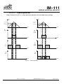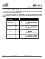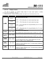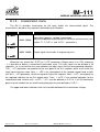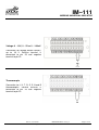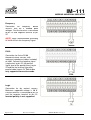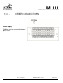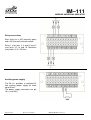
1
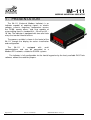
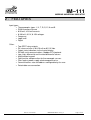
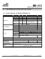
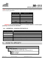
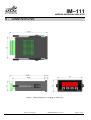
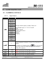
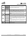
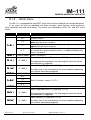
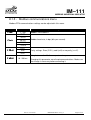
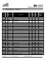
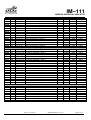
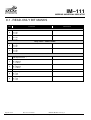
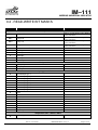
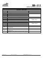
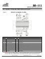
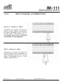
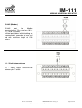
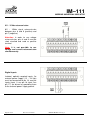
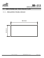
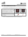
MODBUS UNIVERSAL
INDICATOR
IM–111
User manual
Modbus Universal Indicator
MAN-EN-DE-IM111-01.00_13
Introduction
Thank you for choosing our MODBUS UNIVERSAL INDICATOR IM–111. To ensure its
proper and efficient usage, it’s important to read this user manual thoroughly to understand how to
operate the IM–111, before operating it.
About this Manual
1.
This manual should be delivered to the end user of the IM–111;
2.
The contents of this manual are subject to change without notice;
3.
All rights reserved. No part of this manual may be reproduced in any form without the written
consent from DLG;
4.
The specifications contained herein are limited to standard models and do not cover
customized versions;
5.
All precautions were taken on preparing this manual, in order to guarantee the quality of its
information
CAUTION!
The instrument described in this technical user manual is a device suitable for application in a
specialized technical area. DLG supplied products are submitted to a strict quality control process.
However, industrial control electronic equipment may cause damage to machinery or processes
controlled by them in the event of any failure or improper operations and may even endanger
human lives. The user is responsible for setting and selecting values of the parameters of the
instrument. The manufacturer warns of the risk of incidents with injuries to both people and goods,
resulting from the incorrect use of the instrument.
Contents
1 - PRESENTATION .......................................................................................................................6
2 - FEATURES ................................................................................................................................7
3 - TYPICAL APPLICATIONS ........................................................................................................8
4 - TECHNICAL SPECIFICATIONS ...............................................................................................9
4.1 - ELECTRICAL CHARACTERISTICS .................................................................................. 9
4.2 - GENERAL CHARACTERISTICS ..................................................................................... 10
5 - HOW TO SPECIFY ..................................................................................................................10
6 - DIMENSIONS ..........................................................................................................................11
7 - FUNCTIONALITY ....................................................................................................................12
7.1 - Frontal DISPLAY .............................................................................................................. 12
7.2 - KEYPAD FUNCTIONALITY ............................................................................................. 13
7.2.1 -
Menu navigation ........................................................................................................13
7.2.2 -
Submenu navigation .................................................................................................14
7.2.3 -
Leaving configuration mode ......................................................................................14
7.2.4 -
Locking and unlocking the frontal keypad .................................................................14
7.2.5 -
Ambient temperature indication.................................................................................14
7.2.6 -
Linearization curve input indication ...........................................................................15
8 - CONFIGURATION ...................................................................................................................16
8.1 - SUBMENU DETAILS ....................................................................................................... 16
8.1.1 -
Input menu ................................................................................................................16
8.1.2 -
Alarm menu ...............................................................................................................18
8.1.2.1 -
Alarm operation..................................................................................................19
8.1.2.2 -
Alarm timing .......................................................................................................20
8.1.3 -
Output menu .............................................................................................................21
8.1.4 -
Linearization menu ....................................................................................................22
8.1.5 -
Modbus communications menu.................................................................................23
9 - MODBUS TABLE ....................................................................................................................24
9.1 - READ-ONLY BIT MASKS ................................................................................................ 26
9.2 - READ-write bit masks ...................................................................................................... 27
10 - ELECTRICAL INSTALLATION ...............................................................................................29
10.1 -
REAR CONNECTORS ................................................................................................. 29
10.2 -
INPUT SIGNAL CONNECTION .................................................................................... 30
10.3 -
OTHER CONNECTIONS .............................................................................................. 33
11 - MECHANICAL INSTALLATION ..............................................................................................37
11.1 -
REQUIRED PANEL SPACE ......................................................................................... 37
12 - RECOMMENDATIONS ............................................................................................................38
12.1 -
RS-485 CABLING ......................................................................................................... 39
12.1.1 -
Cable length ..........................................................................................................39
13 - WARRANTY ............................................................................................................................40
IM–111
MODBUS UNIVERSAL INDICATOR
1 - PRESENTATION
The IM–111 (Universal Modbus Indicator) is an
indicator capable of acquiring signals as electric
voltages, currents, frequency, temperature sensors
like Pt100, among others, and also capable of
retransmitting them in standard 0/4 – 20 mA or 0/2 –
10 Vdc. The indicator is equipped with two solid state
relays that can be linked to alarms.
The process variable is shown in the frontal of the
IM–111 through the display for easier visualization
and configuration.
The
IM–111
is
equipped
with
serial
communications and can be connected to a
Modbus/RTU network, suitable for SCADA systems.
The indicator is fully configurable via the frontal keypad or by the freely available DLG Tools
software, without the need for jumpers.
Page 6 of 44
IM–111 User Manual
MAN-EN-DE-IM111-01.00_13
All rights reserved to DLG Automação Industrial
IM–111
MODBUS UNIVERSAL INDICATOR
2 - FEATURES
Input types:
• Thermocouples types J, K, T, R, S, E, N and B
• Pt100 thermoresistance
• 0-20 mA, 4-20 mA currents
• 0-100 mV, 0-5 V, 0-10V voltages
• Frequency
• Logic level
• Digital
Other:
•
•
•
•
•
•
•
•
•
•
Two SPDT relay outputs.
PV retransmission in 0/4-20 mA or 0/2-10 Vdc.
Output state indication via the frontal display.
RS-485 serial communications, Modbus/RTU protocol.
Low, high, differential and inverted differential alarms.
Multifunction keypad.
Cold junction compensation for thermocouple sensors.
Filter against power supply electromagnetic noise.
Communications rate and address configurable by the user.
Detachable rear connection.
IM–111 User manual
MAN-EN-DE-IM111-01.00_13
All rights reserved to DLG Automação Industrial
Page 7 of 44
IM–111
MODBUS UNIVERSAL INDICATOR
3 - TYPICAL APPLICATIONS
•
Temperature indication
•
Motor rotation indication
•
Level indication
•
Pressure indication
•
Variable linearization
•
Flow measurement
Page 8 of 44
IM–111 User manual
MAN-EN-DE-IM111-01.00_13
All rights reserved to DLG Automação Industrial
IM–111
MODBUS UNIVERSAL INDICATOR
4 - TECHNICAL SPECIFICATIONS
4.1 - ELECTRICAL CHARACTERISTICS
Type
Input signal
Input impedance
Parameter
Mín
Max
Current
Voltage
Thermocouple
Pt100
Frequency
0
0
–
–200
0.4
20
10
–
850
30000
Logic level
0
10
Digital
12
24
Current
Voltage
Thermocouple
Pt100
Frequency
Current
Voltage
Thermocouple
Accuracy
Pt100
Frequency
Display
Scale
Sampling time (internal)
Alarms
Auxiliary power supply
J, K, T, R, S, E, N, B
Three wire
0.5 – 60 Vdc sensibility**
0 – 3 Vdc: logic level 0
5 – 10 Vdc: logic level 1
External power supply
required
50
405
280
50
100
±0.1% span
±0.1% span
J, K, T and N
E, R, S and B
±0.1% span
0.1 Hz for 0.4 < f < 1000 Hz
1 Hz for 1000 < f < 30000 Hz
Unit
mA
Vdc
ºC
ºC
Hz
Vdc
Vdc
Ω
KΩ
KΩ
KΩ
KΩ
±(0.1% span + 1°C)
±(0.1% span + 3°C)
Cold junction
0.5
compensation
Five 7-segment displays with decimal point
–9999 a 30000 in engineering units for voltage, current and frequency
10 samples per second
Refresh rate for
frequency input
PV retransmission
Comments
ºC
For 0.4 < f < 999 Hz
480
ms
For f > 1000 Hz
1000
ms
0/4 – 20 mA output with 750 Ω max load or 0 – 10 Vdc output with 30 mA max load.
Accuracy: ±0.1% span.
Two SPDT relay outputs, 3ª/220 Vac each
AL2 SPDT max. 3A/220Vac
24Vdc 50mA
IM–111 User manual
MAN-EN-DE-IM111-01.00_13
All rights reserved to DLG Automação Industrial
Page 9 of 44
IM–111
MODBUS UNIVERSAL INDICATOR
**NOTE.: the table below specifies the minimum voltage level (square wave amplitude) required for the indicator to
detect the frequency signal properly:
Input signal (Hz)
1000
2000
3000
4000
5000
10000
15000
20000
25000
27700
30000
Minimum square wave voltage
amplitude (Vdc)
1.23
1.24
1.25
1.27
1.34
1.80
2.40
3.00
3.70
4.00
4.50
WARNING: When using frequency signals, it is extremely important to consider proper
grounding so noise effects are minimized.
4.2 - GENERAL CHARACTERISTICS
Type
Operating temperature
IP protection
Input voltage
Power consumption
Construction
Electrical connections
Approx. weight
Dimensions
Panel space required
Specification
0 ºC - 50 ºC
IP–20 rear, IP–63 frontal.
IM-111/AC: 90 ~ 240 Vac, 60Hz or 100 ~ 130 Vdc
IM-111/DC: 18 ~ 30 Vdc
5 VA
ABS plastic frontal, for panel mounting
“Plug-in” type removable connectors
0.2 kg
50 x 98 x 152.6 mm (height x width, depth).
42 × 90 mm
5 - HOW TO SPECIFY
IM-__11 /____
Finishing / Enclosure
1
Standalone universal indicator (IM-111)
6
Universal indicator installed inside a IP-65 box (IM-611)
Power
AC
90 ~ 260 Vac
DC
18 ~ 30 Vdc
Page 10 of 44
IM–111 User manual
MAN-EN-DE-IM111-01.00_13
All rights reserved to DLG Automação Industrial
IM–111
MODBUS UNIVERSAL INDICATOR
6 - DIMENSIONS
Figure 1 – Dimensioning for assembling (in millimeters)
IM–111 User manual
MAN-EN-DE-IM111-01.00_13
All rights reserved to DLG Automação Industrial
Page 11 of 44
IM–111
MODBUS UNIVERSAL INDICATOR
7 - FUNCTIONALITY
7.1 - FRONTAL DISPLAY
Figure 2 – Frontal display
Frontal
Functions
Left key, used to navigate through the setup menus. Also
used as Return key to exit the previously active menu.
Right key, used to navigate through the setup menus. Also
used as Enter key to enter the selected menu.
Up key, advances to the next submenu. Also used to
increase parameter values.
Down key, goes back to the previous submenu. Also used to
decrease parameter values.
AL1 and
AL2
Visual indication of relay 1 and 2 states, respectively.
TX and RX Indicates Modbus/RTU transmission (TX) and reception (RX).
Table 1 – Frontal keypad functionality
Page 12 of 44
IM–111 User manual
MAN-EN-DE-IM111-01.00_13
All rights reserved to DLG Automação Industrial
IM–111
MODBUS UNIVERSAL INDICATOR
7.2 - KEYPAD FUNCTIONALITY
The configuration parameters are divided into five groups, called menus, which are in turn
divided into submenus.
7.2.1 - Menu navigation
To switch between menus, simultaneously press the
and
keys at any time.
This combination moves the user to the next menu, regardless of the previously selected submenu.
It is important to note that there is no key to return to the previous menu, so the user must press
the key combination again until the desired menu is found. [If the user is unable to access the menus,
the frontal keypad may be locked; see section 6.2.4]
The menu sequence is depicted below.
Menu
Input
Description
Input type (process variable) settings. User can also set measurement unit for
temperature indication (Celsius or Fahrenheit degrees), engineering scale
minimum and maximum, decimal point for indication, linearization, among
others.
Submenus contained herein are:
In.Set , vn.tep , in.fLo , in.fHi , eng.Lo ,
eng.Hi , dp.pos , of.set , fiLt. , Linea , bv.seL , bv.Lo , bv.Hi
Alarm settings: set points, hysteresis, alarm triggering delay.
Alarms
Submenus contained herein are:
sp.aL1 , fv.aL1 , Hy.aL1 , aL1.t1 ,
aL1.t2 , sp.aL2 , fv.aL2 , Hy.aL2 , aL2.t1 , aL2.t2
Retransmission settings: signal type, engineering scale minimum and maximum,
safety level and calibration (zero and span).
Output
Submenus contained herein are:
ov.set , ov.LoL , ov.HiL , ua.seg , o.zero , o.span
Input signal linearization settings.
Linearization
Submenus contained herein are:
L.in01 ... L.in20 , L.ov01 ... L.ov20
Modbus/RTU settings: address, baud rate, parity and response delay.
Modbus
communications Submenus contained herein are:
C.adr , C.brt , C.pary , C.deLy
IM–111 User manual
MAN-EN-DE-IM111-01.00_13
All rights reserved to DLG Automação Industrial
Page 13 of 44
IM–111
MODBUS UNIVERSAL INDICATOR
7.2.2 - Submenu navigation
Press the
key to advance to a submenu or the
key to return to the previous
submenu.
When a submenu is active, the display will flash between the submenu name and the
parameter value. The parameter value can be changed by pressing the
key and then
entering the new value. After setting the new value, move the cursor to the first or last digit be
pressing the
or
keys. Please note that the display will flash again between the
submenu name and the value set for the parameter.
7.2.3 - Leaving configuration mode
Simultaneously press the
or
and
keys to leave configuration mode. Using the
keys choose between su.yes (save) or su.no (do not save). After choosing
one of the options, press the
key to confirm the action.
7.2.4 - Locking and unlocking the frontal keypad
The frontal keypad can be locked or unlocked by simultaneously pressing the
for 4 seconds while the IM–111 is in normal operation. Using the
choose between
action.
(lock) e
(unlock) and press the
or
and
keys
key to confirm the
7.2.5 - Ambient temperature indication
The IM–111 can indicate the ambient temperature in Celsius or Fahrenheit degrees, as
configured in submenu Input vn.tep.
The temperature will be indicated in the display while the user holds the
releasing the key, the process variable will be restored to the display.
Page 14 of 44
IM–111 User manual
MAN-EN-DE-IM111-01.00_13
All rights reserved to DLG Automação Industrial
key. After
IM–111
MODBUS UNIVERSAL INDICATOR
7.2.6 - Linearization curve input indication
If input signal linearization is enabled, the input signal before linearization can be indicated in
the display by holding the
key while in normal operation. After releasing the key, the
linearized process variable will be restored to the display.
IM–111 User manual
MAN-EN-DE-IM111-01.00_13
All rights reserved to DLG Automação Industrial
Page 15 of 44
IM–111
MODBUS UNIVERSAL INDICATOR
8 - CONFIGURATION
8.1 - SUBMENU DETAILS
8.1.1 - Input menu
Submenu
Parameter
Description
tc j
in.set
in set
tc t
tc r
tc s
tc e
tc n
tc b
pt 100
0.20ma
4.20ma
100mu
5 u
10 u
LogiC
off
freq
Input type selection (process variable). Options are:
Thermocouples type J, K, T, R, S, E, N and B
Pt100
0-20 mA, 4-20 mA
0-100 mV, 0-5 V, 0-10 V
Logic Level
No input
Frequency
C
Ambient temperature indication in Celsius (C) or Fahrenheit (f)
degrees.
F
The chosen unit is displayed when the
key is pressed (see
item 6.2.5) or when the selected input type is thermocouple or
Pt100 (n.set submenu).
vn.tep
vn tep
in.fLo
in fLo
0 - 30000
in.fHi
in fHi
0 - 30000
eng.Lo
eng Lo
eng.Hi
eng Hi
-9999 - 30000
Frequency signal lower limit for engineering unit conversion.
NOTE: Use only when the input type is frequency.
Frequency signal higher limit for engineering unit conversion.
NOTE: Use only when the input type is frequency.
Engineering unit lower limit (display indication).
-9999 - 30000
Engineering unit upper limit (display indication).
Page 16 of 44
IM–111 User manual
MAN-EN-DE-IM111-01.00_13
All rights reserved to DLG Automação Industrial
IM–111
MODBUS UNIVERSAL INDICATOR
dp.pos
dp pos
00000
0000.1
000.02
00.003
0.0004
of.set
of set
-9999 - 30000
fiLt.
fiLt
10 à 100
Linea
off
on
off
Lo
bv.seL
bv seL
Hi
Lo Hi
bv.Lo
bv Lo
bv.Hi
bv Hi
Sets the decimal point position for the input value (process
variable) and for the engineering scale.
Sets the indication offset.
The offset is added to the input variable in engineering units.
Input digital filter. The digital filter calculates the arithmetic mean of
the last input values based on this parameter, by using it as the
number of samples. For instance, if this parameter is 20, the
indicated value will be the arithmetic mean of the last 20 input
samples.
Enables (on) or disables (off) the input signal linearization.
Selects the burn-out behavior. Burn-out is activated when the input
value lies outside the engineering unit range. When the input value
is lower than the engineering unit minimum limit, the lower burnout value is indicated. Similarly, when the input value is higher
than the engineering unit upper limit, the upper burn-out value is
indicated.
The user can disable the burn-out (off), active only the lower limit
(Lo), activate only the upper limit (Hi) or activate both limits
(Hi Lo).
-9999 - 30000
Lower burn-out value.
-9999 - 30000
Upper burn-out value.
IM–111 User manual
MAN-EN-DE-IM111-01.00_13
All rights reserved to DLG Automação Industrial
Page 17 of 44
IM–111
MODBUS UNIVERSAL INDICATOR
8.1.2 - Alarm menu
The IM–111 is equipped with two SPDT relays which can be linked to user configured alarms.
In this menu the user can configure the alarm set point, alarm function, alarm hysteresis,
alarm operation time and alarm delay. The alarms are indicated by LEDs AL1 and AL2 at the
frontal.
Submenu
sp.aL1
sp aL1
Parameter
-9999 - 30000
off
Lo
fv.aL1
fv aL1
Hi
dif
Hy.aL1
Hy aL1
-9999 à 30000
aL1.t1
aL1 t1
0 - 1000 s
aL1.t2
aL1 t2
0 - 1000 s
sp.aL2
sp aL2
-9999 - 30000
fv.aL2
fv aL2
off
Lo
Hi
dif
Hy.aL2
Hy aL2
-9999 - 30000
aL2.t1
aL2 t1
0 - 1000 s
aL2.t2
aL2 t2
0 - 1000 s
Page 18 of 44
Description
Alarm 1 set point.
Disables alarm 1.
Alarm 1 condition is true when the input value (process variable) is
lower than the alarm set point.
Alarm 1 condition is true when the input value (process variable) is
higher than the alarm set point.
Alarm 1 condition is true when the input value (process variable)
lies outside the range around the alarm 1 set point defined by the
alarm 1 hysteresis.
Alarm 1 hysteresis.
Alarm 1 operation time (T1). [see item 7.1.2.2]
The operation time configures for how long the alarm will remain
activated after its triggering.
Alarm 1 delay (T2). [see item 7.1.2.2]
The delay time is the time between the alarm condition becoming
true and the alarm being triggered.
Alarm 2 set point.
Alarm 2 function, same as fv.aL1.
Alarm 2 hysteresis.
Alarm 2 operation time (T1). [see item 7.1.2.2]
The operation time configures for how long the alarm will remain
activated after its triggering.
Alarm 2 delay (T2). [see item 7.1.2.2]
The delay time is the time between the alarm condition becoming
true and the alarm being triggered.
IM–111 User manual
MAN-EN-DE-IM111-01.00_13
All rights reserved to DLG Automação Industrial
IM–111
MODBUS UNIVERSAL INDICATOR
8.1.2.1 - Alarm operation
Figure 3 details the IM–111 alarm operation based on the available alarm settings.
PV
PV
SP.AL + HY
SP.AL + HY
SP.AL
SP.AL
SP.AL - HY
SP.AL - HY
time
Hi
Mode
time
Hi
Mode
with HY
time
time
Lo
Mode
Lo
Mode
with Hy
time
time
OFF
DiF
Mode
Mode
time
time
Figure 3 – Alarm operation.
IM–111 User manual
MAN-EN-DE-IM111-01.00_13
All rights reserved to DLG Automação Industrial
Page 19 of 44
IM–111
MODBUS UNIVERSAL INDICATOR
8.1.2.2 - Alarm timing
The IM–111 alarm timing settings provides several advanced functions to be performed.
Table 2 details the achievable alarm behaviors.
The LEDs for alarm indication (AL1 and AL2) are lit whenever the respective alarm condition
is true, regardless of the output relay state, which may be de-energized based on the timing
functions.
Advanced
function
T1
T2
Normal operation
0
0
Operation
Alarm
output
Alarm condition
Delay
0
1 - 1000 s
Alarm
output
T2
Alarm condition
Pulse
1 - 1000 s
0
Alarm
output
T1
Alarm condition
Oscillator
1 - 1000 s
1 - 1000 s
Alarm
output
T1
T2
Alarm condition
Table 2 – Alarm timing
Page 20 of 44
IM–111 User manual
MAN-EN-DE-IM111-01.00_13
All rights reserved to DLG Automação Industrial
T1
IM–111
MODBUS UNIVERSAL INDICATOR
8.1.3 - Output menu
The IM–111 provides an isolated analog output for input signal (process variable)
retransmission in 0-20 mA or 4-20 mA.
Retransmission is always enabled and does not require user intervention to turn it on.
Submenu
Parameter
Description
Sets the retransmission scale.
e0.20m
e0.20m : 0-20 mA based on the input engineering range.
e4.20m
e4.20m : 4-20 mA based on the input engineering range.
L0.20m
L0.20m : 0-20 mA based on the range defined by the ou.LoLand
ou.HiL parameters.
L4.20m
L4.20m : 4-20 mA based on the range defined by the ou.LoLand
ou.HiL parameters.
ov.set
ov set
Input retransmission lower limit.
ov.LoL
ov LoL
-9999 - 30000
ov.HiL
ov HiL
-9999 - 30000
ua.seg
ua seg
-9999 - 30000
o.zero
zero
-100 - 100
o.span
span
-100 - 100
Only used when the retransmission scale is L0.20m or L4.20m.
Input retransmission upper limit.
Only used when the retransmission scale is L0.20m or L4.20m.
Safe retransmission value.
The safe retransmission value is retransmitted when the input
(process variable) is out of range (burn out).
Calibration “zero” setting.
Changes the lower calibration value. To restore factory calibration,
set this parameter to 0.
Calibration span setting.
Changes the upper calibration value. To restore factory calibration,
set this parameter to 100.
IM–111 User manual
MAN-EN-DE-IM111-01.00_13
All rights reserved to DLG Automação Industrial
Page 21 of 44
IM–111
MODBUS UNIVERSAL INDICATOR
8.1.4 - Linearization menu
The IM-111 provides linearization for the input and/or the retransmitted signal. The
linearization is based on line segments defined by up to 20 points.
Submenu
Parameter
Description
-9999 - 30000
Input signal (process variable) linearization.
May be set between engineering unit minimum and maximum (see
section 7.1.1, eng.Lo and eng.Hi parameters) .
-9999 - 30000
Output signal linearization in engineering units.
L.in01
in01
.
.
.
L.in20
in20
L.ov01
ov01
.
.
.
L.ov20
ov20
When the user selects the L0.20m or L4.20m parameters (Output menu ov.set submenu)
, it is possible to define a customized linearization cycle. The input signal can be divided in 20
segments, so as to minimize the error between the input signal and the corresponding indication.
The L.in01 parameter corresponds to the start point of the first segment, which must match the
input signal minimum value. Next, L.in02 is the starting point of the second segment and so forth
until the L.in20 parameter, which corresponds to the last segment. Next, L.ov01 corresponds to
the required indication for the first output point. Then, L.ov02 is the required indication for the
second point and so forth until L.ov20. L.in01 must be defined as EnG.Lo. If all 20 linearization
points are not needed, the last used linearization point must be defined as EnG.Hi.
The upper and lower indication limits must be defined before the linearization settings.
Page 22 of 44
IM–111 User manual
MAN-EN-DE-IM111-01.00_13
All rights reserved to DLG Automação Industrial
IM–111
MODBUS UNIVERSAL INDICATOR
8.1.5 - Modbus communications menu
Modbus/RTU communications settings can be adjusted in this menu.
Submenu
C.adr
adr
C.brt
brt
C.pary
pary
Parameter
1 - 255
9600
19200
38400
57600
115200
euen
odd
none
Description
Modbus slave address.
Modbus baud rate, in bps (bits per second).
Parity settings. Even (Euen), odd (odd) or no parity (none).
Delay between the Modbus request and response.
C.de
deL
deLy
10 - 200 ms
Changing this parameter can disrupt communications. Make sure
the change is necessary before executing it.
IM–111 User manual
MAN-EN-DE-IM111-01.00_13
All rights reserved to DLG Automação Industrial
Page 23 of 44
IM–111
MODBUS UNIVERSAL INDICATOR
40001
40002
40003
40004
0
1
2
3
EAI1
MSA1
SR01
STDIV
40005
4
TAMB
40006
40007
5
6
R101
LDREL
40008
40009
40010
40011
7
8
9
10
ID
BR0
PAR0
DR0
40012
40013
40014
40015
40016
40017
40018
40019
40020
40021
40022
40023
40024
11
12
13
14
15
16
17
18
19
20
21
22
23
TYPIN
UNTMP
FMNIN
FMXIN
ENGLO
ENGHI
ENGDP
OFSIN
FLTIN
LINON
BRSEL
BRUNDER
BRUPPER
40025
40026
40027
40028
40029
24
25
26
27
28
SPAL1
TPAL1
HTAL1
T1AL1
T2AL1
40030
40031
40032
40033
40034
29
30
31
32
33
SPAL2
TPAL2
HTAL2
T1AL2
T2AL2
40035
40036
40037
34
35
36
LIN_IN_01
LIN_IN_02
LIN_IN_03
Page 24 of 44
Indicated variable (display)
Alarm 1 and 2 status
Relay 1 and 2 status
General status
Ambient temperature (TC cold junction
compensation)
Analog output value
0
Turn on/off relay 1 and 2
0
Modbus communications settings
Slave address
1
Baud rate
1
Parity
2
Response delay
10
Input settings
Input type
13
Temperature unit
0
Minimum input frequency
0
Maximum input frequency
30000
Minimum engineering unit
0
Maximum engineering unit
30000
Decimal point
0
Input offset
0
Input filter
1
Enable linearization
1
Burn-out selection
1
Lower burn-out value
1
Upper burn-out value
1
Alarm 1 configuration
Alarm 1 set point
0
Alarm 1 type
0
Alarm 1 hysteresis
15
Alarm 1 T1
0
Alarm 1 T2
0
Alarm 2 configuration
Alarm 2 set point
0
Alarm 2 type
0
Alarm 2 hysteresis
0
Alarm 2 T1
0
Alarm 2 T2
0
Input linearization
Input linearization – point 1
0
Input linearization – point 2
0
Input linearization – point 3
0
Lower
limit
Description
Upper
limit
Mnemonic
Default
Offset
Address
9 - MODBUS TABLE
Read/Write
Retentive/
Nonretentive
R
R
R
R
120.0
-40.0
100.0
12
0
0
255
4
2
100
0
0
0
0
R/W
R/W
R/W
R/W
R
R
R
R
16
1
30000
30000
30000
30000
3
30000
100
1
3
30000
30000
0
0
0
0
–9999
–9999
0
-9999
0
0
0
–9999
–9999
R/W
R/W
R/W
R/W
R/W
R/W
R/W
R/W
R/W
R/W
R/W
R/W
R/W
R
R
R
R
R
R
R
R
R
R
R
R
R
30000
3
30000
100
100
–9999
0
-9999
0
0
R/W
R/W
R/W
R/W
R/W
R
R
R
R
R
30000
3
30000
100
100
-9999
0
-9999
0
0
R/W
R/W
R/W
R/W
R/W
R
R
R
R
R
30000
30000
30000
-9999
-9999
-9999
R/W R
R/W R
R/W R
IM–111 User manual
MAN-EN-DE-IM111-01.00_13
All rights reserved to DLG Automação Industrial
R
R
R/W
IM–111
MODBUS UNIVERSAL INDICATOR
40038
40039
40040
40041
40042
40043
40044
40045
40046
40047
40048
40049
40050
40051
40052
40053
40054
37
38
39
40
41
42
43
44
45
46
47
48
49
50
51
52
53
LIN_IN_04
LIN_IN_05
LIN_IN_06
LIN_IN_07
LIN_IN_08
LIN_IN_09
LIN_IN_10
LIN_IN_11
LIN_IN_12
LIN_IN_13
LIN_IN_14
LIN_IN_15
LIN_IN_16
LIN_IN_17
LIN_IN_18
LIN_IN_19
LIN_IN_20
40055
40056
40057
40058
40059
40060
40061
40062
40063
40064
40065
40066
40067
40068
40069
40070
40071
40072
40073
40074
54
55
56
57
58
59
60
61
62
63
64
65
66
67
68
69
70
71
72
73
LIN_OUT_01
LIN_OUT_02
LIN_OUT_03
LIN_OUT_04
LIN_OUT_05
LIN_OUT_06
LIN_OUT_07
LIN_OUT_08
LIN_OUT_09
LIN_OUT_10
LIN_OUT_11
LIN_OUT_12
LIN_OUT_13
LIN_OUT_14
LIN_OUT_15
LIN_OUT_16
LIN_OUT_17
LIN_OUT_18
LIN_OUT_19
LIN_OUT_20
40075
40076
40077
40078
40079
40080
40081
40082
40083
74
75
76
77
78
79
80
81
82
RTTYP
RTMIN
RTMAX
BURVAL
OUTZRADJ
OUTSPADJ
INLINVAL
LOCKEY
TMRLOOP
Input linearization – point 4
Input linearization – point 5
Input linearization – point 6
Input linearization – point 7
Input linearization – point 8
Input linearization – point 9
Input linearization – point 10
Input linearization – point 11
Input linearization – point 12
Input linearization – point 13
Input linearization – point 14
Input linearization – point 15
Input linearization – point 16
Input linearization – point 17
Input linearization – point 18
Input linearization – point 19
Input linearization – point 20
Output linearization
Output linearization – point 1
Output linearization – point 2
Output linearization – point 3
Output linearization – point 4
Output linearization – point 5
Output linearization – point 6
Output linearization – point 7
Output linearization – point 8
Output linearization – point 9
Output linearization – point 10
Output linearization – point 11
Output linearization – point 12
Output linearization – point 13
Output linearization – point 14
Output linearization – point 15
Output linearization – point 16
Output linearization – point 17
Output linearization – point 18
Output linearization – point 19
Output linearization – point 20
Analog output
Input retransmission scale
Lower retransmission limit
Upper retransmission limit
Burn-out safe retransmission value
Calibration “zero” setting
Calibration span setting
Linearization input
Keypad lock
Program loop remaining time
0
0
0
0
0
0
0
0
0
0
0
0
0
0
0
0
0
30000
30000
30000
30000
30000
30000
30000
30000
30000
30000
30000
30000
30000
30000
30000
30000
30000
-9999
-9999
-9999
-9999
-9999
-9999
-9999
-9999
-9999
-9999
-9999
-9999
-9999
-9999
-9999
-9999
-9999
R/W
R/W
R/W
R/W
R/W
R/W
R/W
R/W
R/W
R/W
R/W
R/W
R/W
R/W
R/W
R/W
R/W
R
R
R
R
R
R
R
R
R
R
R
R
R
R
R
R
R
0
0
0
0
0
0
0
0
0
0
0
0
0
0
0
0
0
0
0
0
30000
30000
30000
30000
30000
30000
30000
30000
30000
30000
30000
30000
30000
30000
30000
30000
30000
30000
30000
30000
-9999
-9999
-9999
-9999
-9999
-9999
-9999
-9999
-9999
-9999
-9999
-9999
-9999
-9999
-9999
-9999
-9999
-9999
-9999
-9999
R/W
R/W
R/W
R/W
R/W
R/W
R/W
R/W
R/W
R/W
R/W
R/W
R/W
R/W
R/W
R/W
R/W
R/W
R/W
R/W
R
R
R
R
R
R
R
R
R
R
R
R
R
R
R
R
R
R
R
R
4
0
0
0
0
0
4
30000
30000
30000
5000
15000
0
-9999
-9999
-9999
-5000
5000
R
R
R
R
R
R
1
100
0
50
R/W
R/W
R/W
R/W
R/W
R/W
R
R/W
R
IM–111 User manual
MAN-EN-DE-IM111-01.00_13
All rights reserved to DLG Automação Industrial
R
Page 25 of 44
IM–111
MODBUS UNIVERSAL INDICATOR
9.1 - READ-ONLY BIT MASKS
Bit
Function
Comments
Alarm status – address 40002
0
1
Alarm 1
0 = Off
1 = On
Alarm 2
0 = Off
1 = On
Relay status – address 40003
0
1
Relay 1
0 = Off
1 = On
Relay 2
0 = Off
1 = On
General status – address 40004
0
1
2
3
4
5
Page 26 of 44
Calibration memory failure
Not implemented
Lower burn-out
0 = Normal
1 = Failure
Higher burn-out
0 = Normal
1 = Failure
Reserved
Digital input 1
0 = Off
1 = On
Digital input 2
0 = Off
1 = On
IM–111 User manual
MAN-EN-DE-IM111-01.00_13
All rights reserved to DLG Automação Industrial
IM–111
MODBUS UNIVERSAL INDICATOR
9.2 - READ-WRITE BIT MASKS
Value/bit
Function
bit 0
Relay 1 off
bit 1
Relay 2 off
bit 2
Relay 1 on
bit 3
Relay 2 on
0
1
2
3
9600 bps
19200 bps
38400 bps
57600 bps
4
115200 bps
Comments
Turn on/off relay 1 and 2 – address 40007
Write “1” to turn off the relay. Writing
“0” has no effect.
Write “1” to turn off the relay. Writing
“0” has no effect.
Write “1” to turn on the relay. Writing
“0” has no effect.
Write “1” to turn on the relay. Writing
“0” has no effect.
Baud rate – address 40009
Parity – address 40010
0
1
2
Even parity
Odd parity
No parity
Input type – address 40012
0
1
2
3
4
5
Thermocouple type J
Thermocouple type K
Thermocouple type T
Thermocouple type R
Thermocouple type S
Thermocouple type E
6
7
8
9
10
11
Thermocouple type N
Thermocouple type B
Pt100
0–20 mA
4–20 mA
0–100 mV
12
13
14
15
16
0–5 V
0–10 V
Logic
No input
Frequency
Temperature unit – address 40013
0
Celsius degrees
IM–111 User manual
MAN-EN-DE-IM111-01.00_13
All rights reserved to DLG Automação Industrial
Page 27 of 44
IM–111
MODBUS UNIVERSAL INDICATOR
1
Fahrenheit degrees
Linearization – address 40021
0
1
Disabled
Enabled
Burn-out selection – address 40022
0
1
2
3
Burn-out OFF
Burn-out LOW
Burn-out HIGH
Burn-out LOW and HIGH
0
1
2
3
Alarm
Alarm
Alarm
Alarm
0
1
2
3
Alarm
Alarm
Alarm
Alarm
Alarm type 1 – address 40026
0
1
2
3
Page 28 of 44
1 OFF
1 LOW
1 HIGH
1 DIFFERENTIAL
Alarm type 2 – address 40031
2 OFF
2 LOW
2 HIGH
2 DIFFERENTIAL
Input retransmission scale – address 40075
0 – 20 mA or 0 – 10 V retransmission based on the input
engineering range
0 – 20 mA or 0 – 10 V retransmission based on lower and upper
limits
4 – 20 mA or 2 – 10 V retransmission based on the input
engineering range
4 – 20 mA or 2 – 10 V retransmission based on lower and upper
limits
IM–111 User manual
MAN-EN-DE-IM111-01.00_13
All rights reserved to DLG Automação Industrial
Triggers relay 1
Triggers relay 2
IM–111
MODBUS UNIVERSAL INDICATOR
10 - ELECTRICAL INSTALLATION
10.1 -
REAR CONNECTORS
Connectors
Pin
1
2
3
Function
L1
L2
Relay 2 (NO connection)
Pin
13
14
15
Relay 1 (NO connection)
Relay 1 (common)
Relay 1 (NC connection)
Function
4
5
6
7
8
9
Relay 2 (common)
Relay 2 (NC connection)
Not used
Retransmission (GND)
Retransmission (mA)
Retransmission (Vdc)
16
17
18
19
20
21
Digital input 1
Digital input 2
Digital inputs (common)
24 Vdc (auxiliary power supply)
GND (auxiliary power supply)
Input (mA)
10
11
12
485+
485–
485 shield
22
23
24
Input (GND)
Input (Vdc and frequency)
Input (RTD)
NOTE: when the voltage output is used, the voltage output must be short-circuited with the
current output (pins 8 and 9) and this connection must be used as the positive terminal.
IM–111 User manual
MAN-EN-DE-IM111-01.00_13
All rights reserved to DLG Automação Industrial
Page 29 of 44
IM–111
MODBUS UNIVERSAL INDICATOR
10.2 -
INPUT SIGNAL CONNECTION
Current: 0 ~ 20mA or 4 ~ 20mA
Connection for sensors that actively
transmit current (different connections
for signal and power) up to 20 mA.
Positive signal is connected to pin 21
and negative signal to pin 22. Inverted
connections are not supported.
XTR: 0 ~ 20mA or 4 ~ 20mA
Connection for sensors that passively
transmit current (same connection for
signal and power) up to 20 mA. Positive
signal is connected to pin 21 and
negative signal to pin 21.
Page 30 of 44
IM–111 User manual
MAN-EN-DE-IM111-01.00_13
All rights reserved to DLG Automação Industrial
IM–111
MODBUS UNIVERSAL INDICATOR
Voltage: 0 ~ 10V, 0 ~ 5V or 0 ~ 100mV
Connection for voltage based sensors,
up to 10 V. Positive terminal is
connected to pin 23 and negative
terminal to pin 22.
Thermocouple
Connection for J, K, T, R, S, E, N and B
thermocouples. Positive terminal is
connected to pin 23 and negative
terminal to pin 22.
IM–111 User manual
MAN-EN-DE-IM111-01.00_13
All rights reserved to DLG Automação Industrial
Page 31 of 44
IM–111
MODBUS UNIVERSAL INDICATOR
Frequency
Connection for frequency based
sensors, with 50 V allowed peak
voltages. Positive terminal is connected
to pin 23 and negative terminal to pin
22.
NOTE: Apply recommended grounding
to avoid noise in the frequency signal.
Pt100
Connection for 3-wire Pt100
thermoresistance sensors, with
maximum impedance (cables included)
of 440Ω. Connect the negative signal
(single wire) to pin 22, the positive
signal (one of the parallel wires) to pin
23 and the line terminal (the other
parallel cable) to pint 24. This is the
only supported connection mode.
Logic
Connection for dry contact sensors.
Maximum supported voltage is 10 V.
Positive terminal is connected to pin 23
and the negative terminal to pin 22.
Inverted polarity is not supported.
Page 32 of 44
IM–111 User manual
MAN-EN-DE-IM111-01.00_13
All rights reserved to DLG Automação Industrial
IM–111
MODBUS UNIVERSAL INDICATOR
10.3 -
OTHER CONNECTIONS
Power supply
240 Vac must be connected between
pins 1 and 2.
IM–111 User manual
MAN-EN-DE-IM111-01.00_13
All rights reserved to DLG Automação Industrial
Page 33 of 44
IM–111
MODBUS UNIVERSAL INDICATOR
Relay connections
Each relay has a NO (normally open)
and a NC (normally closed) contact.
Relay 1 uses pins 3, 4 and 5; relay 2
uses pints 13, 14 and 15. Maximum
relay load is 3 A / 220 Vac.
Auxiliary power supply
The IM–111 provides a regulated 24
Vdc auxiliary power supply for loads
up to 50 mA.
The power supply connectors are pin
19 (+) and 20 (-).
Page 34 of 44
IM–111 User manual
MAN-EN-DE-IM111-01.00_13
All rights reserved to DLG Automação Industrial
IM–111
MODBUS UNIVERSAL INDICATOR
RS-485 (Modbus)
RS-485
port
for
Modbus
communications. Pins used are 10 (+),
11 (-) and 12 (shield).
Twisted pair cables with shielding are
recommended, grounded at one end
and with maximum length of 1200
meters.
0/4 ~ 20mA retransmission
0/4 ~ 20mA signal retransmission
between pins 7 and 8.
IM–111 User manual
MAN-EN-DE-IM111-01.00_13
All rights reserved to DLG Automação Industrial
Page 35 of 44
IM–111
MODBUS UNIVERSAL INDICATOR
0/2 ~ 10Vdc retransmission
0/2 ~ 10Vdc signal retransmission
between pins 8 and 9 (positive) and
pin 7 (negative).
Attention: in order to use voltage
retransmission, pins 8 and 9 must be
short circuited and used as positive
terminal.
Note: it is not possible to use
voltage and current retransmission
simultaneously.
Digital inputs
Isolated, optically coupled inputs. An
external power supply (12 ~ 24 Vdc)
must be connected to pin 18, and the
inputs (input 1 is on pin 16, input 2 on
pin 17) are driven by grounding them
to the external power supply ground.
Page 36 of 44
IM–111 User manual
MAN-EN-DE-IM111-01.00_13
All rights reserved to DLG Automação Industrial
IM–111
MODBUS UNIVERSAL INDICATOR
11 - MECHANICAL INSTALLATION
11.1 - REQUIRED PANEL SPACE
42 mm
90 mm
IM–111 User manual
MAN-EN-DE-IM111-01.00_13
All rights reserved to DLG Automação Industrial
Page 37 of 44
IM–111
MODBUS UNIVERSAL INDICATOR
12 - RECOMMENDATIONS
It is recommended to use only appropriate tools for the IM–111 installation and maintenance.
It is necessary to use a “terminal” type
screwdriver for terminal connection or 1/8 with
3mm maximum diameter, as it is the ideal format
and will not damage the connection aperture.
It is recommended to crimp all the wires that will
be connected to the IM-111 with a pre-isolated
“needle” type or “eyelet” type terminal for cables
of 0,5 ~ 1,5mm2.
Inappropriate
screwdriver
Needle terminal
Recommended
screwdriver
Eyelet terminal
The IM–111 is designed to be frontal panel mounted, free of humidity or dust.
Page 38 of 44
IM–111 User manual
MAN-EN-DE-IM111-01.00_13
All rights reserved to DLG Automação Industrial
IM–111
MODBUS UNIVERSAL INDICATOR
12.1 - RS-485 CABLING
The RS-485 cable should have low capacitance, inductance and resistance per meter. It is
recommended specific cabling for long distance, high bandwidth data communications.
The data communications cable must be installed away from noise sources, like motors,
drives and high voltage cables.
12.1.1 - Cable length
Cable length must be specified according to required bandwidth and depends on the cable
electrical properties (impedance and signal rise time). Maximum distance is 1200 meters with 9600
bps bandwidth.
IM–111 User manual
MAN-EN-DE-IM111-01.00_13
All rights reserved to DLG Automação Industrial
Page 39 of 44
IM–111
MODBUS UNIVERSAL INDICATOR
13 - WARRANTY
The manufacturer assures to equipment owners, identified by the purchase invoice, warranty
of 1 (one) year as follows:
1. The warranty period begins with the invoice issuing.
2. Within the warranty period, the labor and parts used for repairing normal use damage are
free.
3. For repairs, send the equipment along with the shipping invoices to our factory in
Sertãozinho. DLG’s address is available at the end of this manual.
4. The owner is responsible for transportation costs and risks.
5. Warranty will be automatically suspended if changes are made to the equipment by
personnel not authorized by DLG, defects caused by mechanical shock, exposure to
conditions unfit for use of tampering with the product.
6. DLG disclaims any charge relating to unauthorized repairing or replacements due to
failures caused by agents external to the equipment, the improper use of them and as a
result of unforeseeable circumstances or major forces.
7. DLG ensures full operation of the equipment described herein and all existing operations.
Page 40 of 44
IM–111 User manual
MAN-EN-DE-IM111-01.00_13
All rights reserved to DLG Automação Industrial
Notes
DLG Automação Industrial Ltda.
Rua José Batista Soares, 53
Distrito Industrial – 14176-119
Sertãozinho – São Paulo – Brasil
Fone: +55 (16) 3513-7400
www.dlg.com.br
MAN-EN-DE-IM11101.00_13
UNIVERSAL MODBUS INDICATOR
IM-111
DLG reserves the right to change this manual contents without notice in
order to keep it updated with potential product developments.