1
novaPLC 2.0
3
Control We Write a Little Program
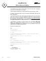
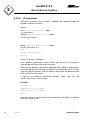
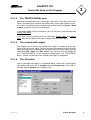
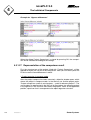
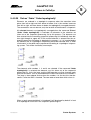
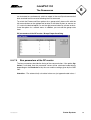
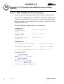
3.1.1.3
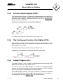
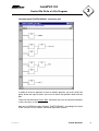
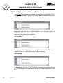
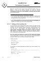
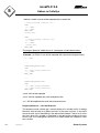
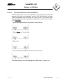
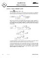
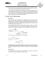
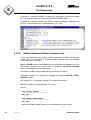
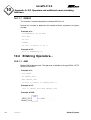
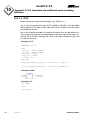
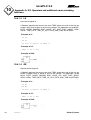
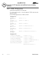
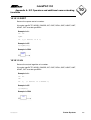
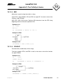
What does SEQUENCE do?
In SEQUENCE all is combined so that the right light lights up at the right time
for the desired time period.
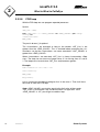
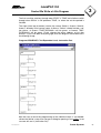
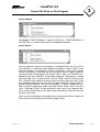
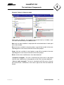
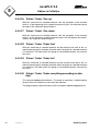
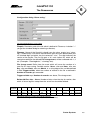
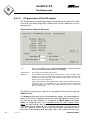
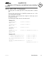
3.1.1.4
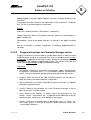
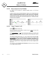
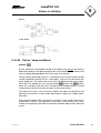
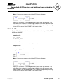
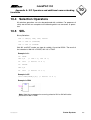
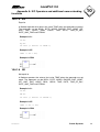
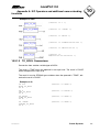
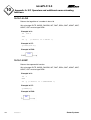
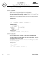
What does PLC_PRG do?
In PLC_PRG the input start signal is connected to the traffic lights' sequence
and the "color instructions" for each lamp are provided as outputs.
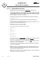
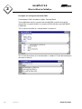
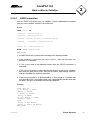
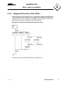
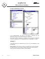
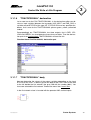
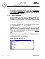
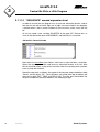
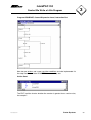
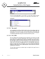
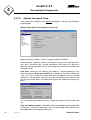
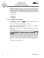
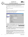
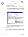
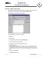
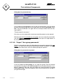
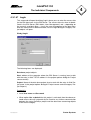
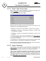
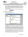
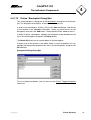
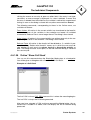
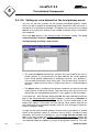
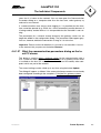
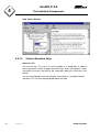
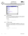
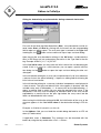
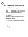
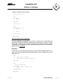
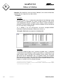
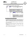
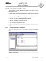
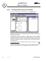
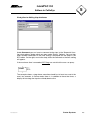
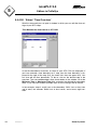
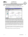
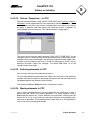
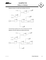
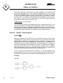
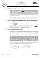
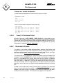
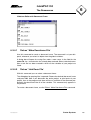
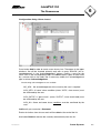
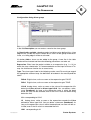
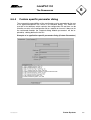
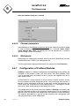
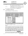
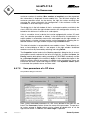
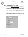
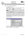
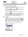
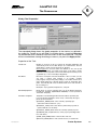
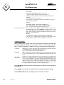
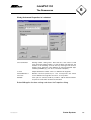
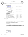
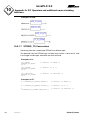
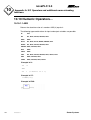
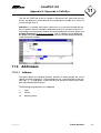
3.1.1.5
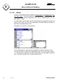
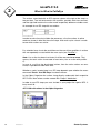
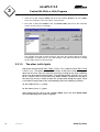
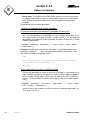
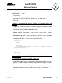
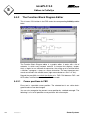
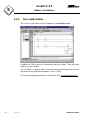
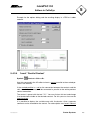
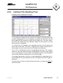
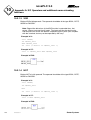
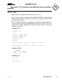
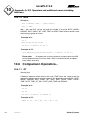
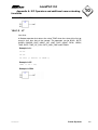
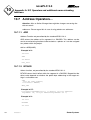
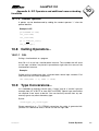
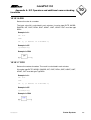
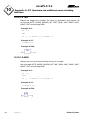
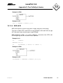
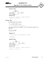
TRAFFICSIGNAL simulation
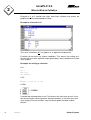
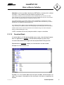
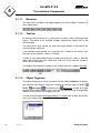
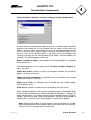
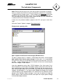
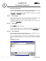
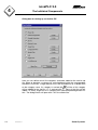
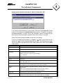
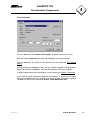
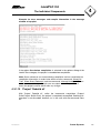
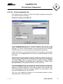
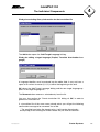
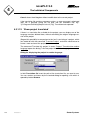
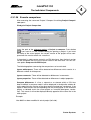
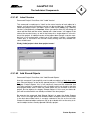
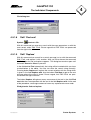
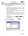
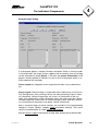
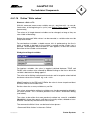
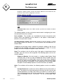
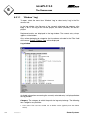
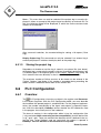
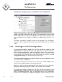
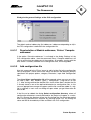
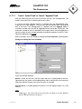
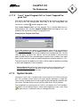
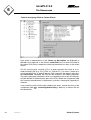
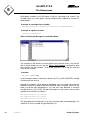
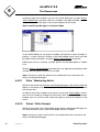
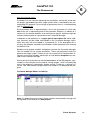
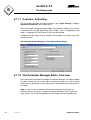
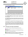
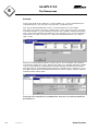
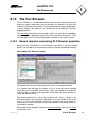
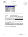
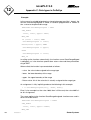
Now test your program in simulation mode. Compile ('Project' 'Build') and load
('Online' 'Login') it. Start the program by 'Online' 'Start', then set variable ON
to TRUE, e.g. by a double-click on the entry "ON" in the input box of the CFC
editor. This will mark the variable as prepared to be set to <TRUE>. Then press
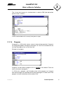
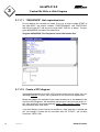
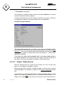
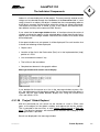
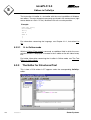
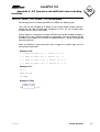
<Ctrl><F7> or command 'Online' 'Write values', to set the value. Now variable
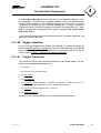
START in ABLAUF (which we had set to TRUE manually in the first extension
level of the program) gets this value by variable ON, which is used in
PLC_PRG. This will make run the traffic light cycles. PLC_PRG has changed to
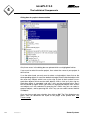
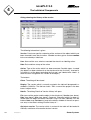
a monitoring window. Click twice on the plus sign in the declaration editor, the
variable display drops down, and you can see the values of the individual
variables.
78
7001066003 S1
Sauter Systems