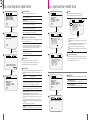
1
x10
Anti-vandal
Speed Dome Camera
User’s Manual
Safety Information
CAUTION
RISK OF ELECTRIC SHOCK.
DO NOT OPEN.
CAUTION:
TO REDUCE THE RISK OF ELECTRIC SHOCK, DO NOT REMOVE COVER (OR BACK) NO USER SERVICEABLE
PARTS INSIDE. REFER SERVICING TO QUALIFIED SERVICE PERSONNEL.
Warning
Precaution
This symbol indicates that dangerous voltage
consisting a risk of electric shock is present within
this unit.
This exclamation point symbol is intended to alert the
user to the presence of important operating and
maintenance (servicing) instructions in the literature
accompanying the appliance.
WARNING
To prevent damage which may result in fire or electric shock hazard, do not expose this appliance to rain or moisture.
WARNING
1. Be sure to use only the standard adapter that is specified in the specification sheet. Using any other adapter could
cause fire, electrical shock, or damage to the product.
2. Incorrectly connecting the power supply or replacing battery may cause explosion, fire, electric shock, or damage
to the product.
3. Do not connect multiple cameras to a single adapter. Exceeding the capacity may cause abnormal heat generation
or fire.
4. Securely plug the power cord into the power receptacle. Insecure connection may cause fire.
5. When installing the camera, fasten it securely and firmly. A falling camera may cause personal injury.
6. Do not place conductive objects (e.g. screw drivers, coins, metal things, etc.) or containers filled with water on top
of the camera. Doing so may cause personal injury due to fire, electric shock, or falling objects.
7. Do not install the unit in humid, dusty, or sooty locations. Doing so may cause fire or electric shock.
8. If any unusual smells or smoke come from the unit, stop using the product. In such case, immediately disconnect
the power source and contact the service center. Continued use in such a condition may cause fire or electric shock.
9. If this product fails to operate normally, contact the nearest service center. Never disassemble or modify this
product in any way.
x10 Anti-vandal
Speed Dome Camera
10. When cleaning, do not spray water directly onto parts of the product. Doing so may cause fire or electric shock.
User’s Manual
Ver. 3 . 1 / 2009.09
2
3
Precautions
Contents
Operating
Before using, make sure power supply and others are properly connected.
While operating, if any abnormal condition or malfunction is observed, stop using the camera immediately and then
contact your Special dealer.
4 Precation
1. Introduction
7 Parts Name & Functions
Handling
Do not disassemble or tamper with parts inside the camera.
Do not drop or subject the camera to shock and vibration as this can damage camera.
Care must be taken when you clean the clear dome cover. Especially, scratch and dust will ruin your quality of camera.
6 Product & Accessories
2. Installation
8 DIP Switch Setup
10 Installation Using Surface Mount Bracket
Installation and Storage
11 Installation Using Flush Mount Ring Bracket(Option)
Do not install the camera in areas of extreme temperature, which exceed the allowable range.
Avoid installing in humid or dusty places.
Avoid installing in places where radiation is present.
Avoid installing in places where there are strong magnetic fields and electric signals.
Avoid installing in places where the camera would be subject to strong vibrations.
Never expose the camera to rain and water.
12 Installation Using Ceiling Mount Bracket(Option)
13 Installation Using Wall Mount Bracket(Option)
14 Installation Using Wall Mount Bracket with Junction Box(Option)
16 Cabling the 5P Terminal Block
17 Cabling the 7P Terminal Block
3. OSD Menu
18 Check Points before Operation
19 Main Functions
20 OSD Information
21 General Rules of Menu Operation
22 OSD Menu Contents
24 OSD - ROOT MENU & SYSTEM INFORMATION
25 OSD - DISPLAY SETUP
26 OSD - MOTION SETUP
28 OSD - FUNCTION SETUP>PRESET SETUP
30 OSD - FUNCTION SETUP>SCAN SETUP
31 OSD - FUNCTION SETUP>PATTERN SETUP
32 OSD - FUNCTION SETUP>GROUP SETUP
34 OSD - FUNCTION SETUP>SCHEDULE SETUP
36 OSD - CAMRA SETUP>WB SETUP
37 OSD - CAMRA SETUP>AE SETUP
38 OSD - SYSTEM SETUP
40 OSD - SYSTEM INITIALIZE
4. Specification
41 Dimensions
42 Dimensions of Option Brackets
44 Specifications
4
5
1
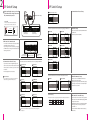
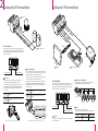
Product & Accessories
Parts Name & Functions
Please check if all the camera and
accessories are included in the package.
1 Dome Cover
1 Main Body
Camera module, screws, terminal block slot and
DIP switches are included.
2 Lockup Screw
Fixes main body to the surface mount bracket.
2 Surface Mount Bracket
- It is used when installing the camera right on to
the ceiling.
- To install the camera with the surface mount
bracket, the bracket needs to be separated from
the main body, then needs to be re-assembled
the bracket and the main body according to the
order.
3 Screw & Plastic Anchor
- Screws are used to fix the surface mount bracket
to the ceiling.
- Plastic anchors are used to tighten the screws to
the hole by inserting them into the holes in
advance.
2 Lockup Screw
Main Body
3 7P Terminal Block Slot
1 Main Body + 2 Surface Mount Bracket
4 Terminal Block
Power, video, communication and alarm input
cables are connected through the terminal blocks.
5 Torx Screw Driver
It is used to screw/unscrew the fixed screws on
the main body.
1 Dome Cover
- Protects the camera module from outside
environment.
- Do not detach protection vinyl from the dome
cover before finishing all installation processes
to protect dome cover from scratches or dust.
4 DIP Switch
5 5P Terminal Block Slot
6 Mounting Hole
This is used to attach the surface mount bracket
to the ceiling.
Bottom of Main Body
6 Mounting Hole
7 Manual
Please read the manual carefully before installing.
4 DIP Switch
- Adjusts camera ID and protocols.
- Refer page 8, 9 for details.
5 5P Terminal Block Slot
- Alarm input and relay out cables are connected to
this terminal block.
- Refer page 16 for details.
3 Screw & Plastic Anchor-4pcs
6 Rubber Gasket
It is installed between the surface mount bracket
and wall/wall mount bracket to prevent the water
leakage.
3 7P Terminal Block Slot
- Power, keyboard controller/DVR video device are
connected to this terminal block.
- Refer page 17 for details.
7 ¾” Pipe Mounting Hole
- This is used to pass the cables to the cameras.
- When water protection is needed, connect the
¾” pipe through this hole, then pass the cables
through the pipe.
7 ¾” Pipe Mounting Hole
4 Terminal Block x2: 5P+7P
5 Torx Screw Driver
Surface Mount Bracket
User
’s
6 Rubber Gasket
6
Manu
al
7 Manual
7
2
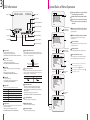
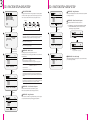
DIP Switch Setup
DIP Switch Setup
Before installing the camera, you should
set the DIP switch to configure the camera
ID, communication protocol.
Bottom of Main Body
If the pin is located ‘ON’ side of the printed
label, it means on. In reverse, means off.
ON
1
Pin On
ON
Pin Off
1
ON
1 2 3 4 5 6 7 8
Pin On/Off
ON
2. Communication Protocol Setup
7 AD(American Dynamics)
ON
Choose the appropriate baud rate protocol by setting the DIP switch
1 2 3 4 5 6 7 8
DIP Switch for
Communication
1. DIP Switch for Communication
8J
1
2
3
4
5
6
7
8
DIP Switch for
Camera ID Setup
ON
- It is consist of communication protocol, baud rate
and RS-485 termination setup pins.
- If you change the camera protocol by changing
the DIP switch, the change will be effective after
rebooting the camera.
2 4800 BPS
ON
ON
1 2 3 4 5 6 7 8
1 2 3 4 5 6 7 8
3 9600 BPS
1 2 3 4 5 6 7 8
Communication
Protocol Setup Pin
1 2400 BPS
Baud Rate Setup Pin
RS-485 Termination
Setup Pin
3. Baud Rate Setup
- Select the appropriate baud rate with DIP switch
combination.
- The factory default is 9600BPS.
4 19200 BPS
ON
ON
1 2 3 4 5 6 7 8
1 2 3 4 5 6 7 8
5 38400 BPS
2. Communication Protocol Setup
- If you want to control using DVR or keyboard
controller, their protocol must be identical to the
camera’s protocol. Otherwise, you cannot control
the camera.
- The factory default is auto protocol.
Choose the appropriate communication protocol by setting the DIP switch.
1 Auto Protocol
2 PELCO-D
ON
ON
1 2 3 4 5 6 7 8
1 2 3 4 5 6 7 8
1 Auto Protocol
- If you set the protocol as auto protocol, camera will
automatically recognize the kind of protocol.
3 PELCO-P
4 SAMSUNG
ON
ON
1 2 3 4 5 6 7 8
1 2 3 4 5 6 7 8
5 Panasonic
ON
1 2 3 4 5 6 7 8
6 GE(Kalatel)
ON
1 2 3 4 5 6 7 8
If there is other combination of pins from above, it will be recognize as
auto protocol.
8
ON
1 2 3 4 5 6 7 8
Choose the termination resistor on/off to notify the last camera.
1 Normal
2 Last Camera
ON
ON
1 2 3 4 5 6 7 8
1 2 3 4 5 6 7 8
Camera ID Setup
4. RS-485 Termination Setup
- Pin 8 is use for on/off of RS-485 termination.
Normally, it must be off state.
- Especially, when you have trouble with long daisy
chain style connection, turn on this termination
switch of the last camera.
5. DIP Switch for Camera ID Setup
- ID number of camera is set using binary number. The example is shown below.
Pin
1
2
3
4
5
6
7
8
ID Value
1
2
4
8
16
32
64
128
- If you want to control a certain camera, you must
match the camera ID with ‘CAM ID, setting of DVR
or keyboard controller.
- ID number of the camera is set using binary number.
- The range of ID is 0~255. Factory default of
camera ID is 1.
- Camera ID will be effective without rebooting
the camera.
9
2
Installation Using Surface Mount Bracket
1 Drilling the Hole on the Ceiling
To pass cables through the ceiling, drill a hole
(30mm diameter) on the ceiling panel.
2 Fix the Surface Mount Bracket
Pass the cables to the ¾” pipe hole, and screw
the surface mount bracket to the ceiling.
Installation Using Flush Mount Ring Bracket (Option)
1 Drilling the Hole on the Ceiling
1 Drilling the Hole
on the Ceiling
1 Drilling the Hole on the Ceiling
To pass cables through the ceiling, drill a
hole(70mm diameter) on the ceiling.
2 Separate the Lock-up Screws from the
Rubber Gasket
Main Body
Separate the 4 lock-up screws from the main body
in advance.
Rubber Gasket
- Before installing the gasket, the hole in the center
is to be cut by knife when only necessary.
- When installing gasket, the protrusion of the
gasket should be matched with the groove joint
of the bottom of the surface mount bracket.
2 Fix the Surface
Mount Bracket
2 Separate the Lock-up
Screws from the Main
Body
4 Wire the Cables and
Terminal Blocks
3 Connect the Cables
- Connect wire cables to the terminal blocks.
- Refer page 16, 17 for details.
4 Connect the Terminal Blocks
Connect the terminal blocks to the main body.
3 Fix the Flush Mount Ring Bracket to the
Main Body
Fix the flush mount ring bracket to the main body
using torx screws.
4 Connect Wire the Cables and Terminal Blocks
Connect wire cables to the terminal blocks.
Refer page 16, 17 for details.
3 Connect the Cables
3 Fix the Flush Mount
Ring Bracket to the
Main Body
5 Fix the Main Body
Screw the main body with the surface mount
bracket to the ceiling using the screws on the
surface mount bracket.
6 Detach the Protection Vinyl
Detach the protection vinyl from the dome cover.
4 Connect the
Terminal Blocks
5 Fix the Main Body
5 Fix the Main Body
Screw the main body to the surface mount bracket
by screwing 4 lock-up screws.
5 Fix the Main Body
6 Detach the Protection Vinyl
Detach the protection vinyl from the dome cover.
6 Detach the
Protection Vinyl
10
11
2
Installation Using Ceiling Mount Bracket (Option)
1. Installing on the Concrete Ceiling
2 Fix the Wall Mount Bracket
1 Drill the Ceiling and Fix the Anchor Bolts
On the ceiling, drill a hole (6mm diameter/ 50mm
depth), and fix the anchor bolts.
2 Fix the Ceiling Mount Bracket
1. Drill a hole (20mm diameter) on the pipe of the
bracket to pass the cables.
2. On the fixed anchor bolts, attach the rubber
gasket and screw the ceiling mount bracket.
2. Installing on the Wooden Ceiling
Installation Using Wall Mount Bracket (Option)
Rubber Gasket
1 Drill the Ceiling and
Fix the Anchor Bolts
2 Fix the Ceiling
Mount Bracket
2. Installing on the Wooden Wall
1 Drill the Wall and
Fix the Anchor Bolts
Rubber Gasket
2 Fix the Ceiling Mount Bracket
Pass the cables into the ceiling mount bracket,
and screw the ceiling mount bracket to the
ceiling.
3 Fix the Surface Mount Bracket
1 Drill the Wall
To pass cables to the wall, make a hole about
30 mm on the wall.
2 Fix the Wall Mount Bracket
Pass the cables into the wall mount bracket,
and screw the wall mount bracket to the wall.
3 Fix the Surface Mount Bracket
Pass the cables through the hole of the surface
mount bracket, screw the surface mount bracket
to the wall mount bracket.
3 Fix the Surface Mount Bracket
Pass the cables through the hole of the surface
mount bracket, screw the surface mount bracket
to the ceiling mount bracket.
4 Wire Cables
Wire the cables to the terminal block.
Refer page 16, 17.
4 Wire Cables
Wire the cables to the terminal block.
Refer page 16, 17.
5 Connect the Terminal Blocks
Connect terminal block to the main body.
Refer page 10.
1 Drill the Wall and Fix the Anchor Bolts
On the wall, drill a hole (6mm diameter/50mm
depth), and fix the anchor bolts.
2 Fix the Wall Mount Bracket
1. Drill a hole (20mm diameter) on the pipe of the
bracket to pass the cables.
2. On the fixed anchor bolts, attach the rubber
gasket and fix the wall mount bracket with nuts
and screws.
Rubber Gasket
1 Drill the Ceiling
To pass cables to upside of ceiling, drill a hole
(30mm diameter) on the ceiling.
1. Installing on the Concrete Wall
5 Connect the Terminal Blocks
Connect terminal block to the main body.
Refer page 10.
3 Fix the Surface
Mount Bracket
6 Fix the Main Body
Screw the main body to the surface mount bracket.
(Screws are included in the main body.)
4 Wire Cables
5 Connect the Terminal Blocks
6 Fix the Main Body
6 Fix the Main Body
Screw the main body to the surface mount bracket.
(Screw are included in the main body.)
7 Detach the Protection Vinyl
Detach the protection vinyl from the dome cover.
7 Detach the Protection Vinyl
Detach the protection vinyl from the dome cover.
4 Wire Cables
5 Connect the
Terminal Blocks
6 Fix the Main Body
7 Detach the Protection Vinyl
7 Detach the
Protection Vinyl
12
13
2
Installation Using Wall Mount Bracket with Junction Box (Option)
1 Drill the Wall to Fix the Anchor Bolts
On the wall, drill a hole (6mm diameter/50mm
depth) for fix the anchor bolts.
6 Wire Cables
Wire the cables to the terminal block.
Refer page 16, 17.
2 Pass Cables through the Wall Mount
7 Connect the Terminal Blocks
Connect terminal blocks to the main body.
Refer page 10.
Bracket
Pass cables before fixing the wall mount
bracket.
3 Fix the Junction Box
Fix the junction box to anchor bolts on the wall.
8 Fix the Main Body
Screw the main body to the surface mount bracket.
(Screws are included in the main body.)
2 Pass Cables through
the Wall Mount Bracket
9 Detach the Protection Vinyl
Detach the protection vinyl from the dome cover.
4 Close Junction Box Cover
Close cover to the junction box using the torx driver.
5 Fix the Sun Shield Bracket
Fix the sun shield bracket to the wall mount bracket.
3 Fix the Junction Box
6 Wire Cables
1 Drill the Wall to
Fix the Anchor Bolts
7 Connect the Terminal Blocks
8 Fix the Main Body
9 Detach the Protection Vinyl
4 Close the Junction Box Cover
5 Fix the Sun Shield Bracket
14
15
2
Cabling the 5P Terminal Block
Cabling the 7P Terminal Block
1 Relay Out
5P Terminal Block
BNC Video
2 Sensor/Alarm Input
5p terminal block connects the sensor/alarm input and the
relay out device to the camer’s main body. (Refer ‘Installation
Using Surface Mount Bracket’ of page 10 for the connection
of the terminal block.)
Relay Out Input Slot
Sensor/Alarm Input Slot
1 Relay Out
- It connects to the alarm lights, siren or lamps, and it is
activated according to the OSD menu setting.
- If you want to use relay out, the types of sensor must be
selected in OSD menu (ROOT MENU>SYSTEM SETUP>
RELAY TYPE). The sensor types are normal open and
normal close.
Normal Open
(N.O)
Output voltage is high state when sensor is
activated.
Normal Close
(N.C)
Output voltage is high state when sensor is not
activated.
2 Sensor/Alarm Input
- It connects to IR sensor, IrDA sensor or door switch. If the
sensor is activated, it can activate to move camera to the
specific angle and to connect the alarm device.
- A cable of the sensor should connect to input 1 or 2, and
the other should be connected to ‘COM’ slot.
- If you want to use alarm input, the types of sensor must be
selected in OSD menu (ROOT MENU>MOTION SETUP>
ALARM INPUT SETUP). The sensor types are normal open
and normal close.
Normal Open
(N.O)
Output voltage is high state when sensor is
activated.
Normal Close
(N.C)
Output voltage is high state when sensor is not
activated.
1 Monitor
3 Power
2 Keyboard Controller/DVR
7P Terminal Block
7p terminal block connects the power, keyboard controller/
DVR or video device and etc to the camera’s main body.
(Refer ‘Installation Using Surface Mount Bracket’ of page 10
for the connection of the terminal block.)
2 Keyboard Controller/DVR
Controls PTZ by connecting with keyboard controller or
DVR using RS-485 communication standards.
~
Keyboard Controller/DVR
Camera 1
Out
N.O
In 2
COM
Activation
In 2
COM
In 2
N.C
<Inside of terminal block: Activation type of relay out N.O.>
Power Input Slot
Video Input Slot
RS-485 Communication Input Slot
COM
16
Camera 2
Camera n
Out
In 2
COM
Activation
In 2
<Inside of terminal block: Activation type of alarm input N.O. / N.C.>
COM
1 Monitor
Connects to video output device such as monitor using the
BNC coaxial cable.
3 Power
- Please check the correct rated power.
- The rated power is marked on the bottom of the camera.
Power
Range
Power Consumption
DC 12V
DC 11V ~ 15V
8W
Fan/Heater model consumes 12W.
17
3
Check Points before Operation
Main Functions
Check Points before Operation
1 Preset
- Max. 127 positions can be stored as preset positions.
The preset number can be assigned from 1 to 128, but 95
is reserved for starting OSD menu.
- Refer page 28 - ‘ROOT MENU>FUNCTION SETUP>PRESET
SETUP’ for more detailed information.
1. Before power is applied, please check the cables carefully.
2. The camera ID of the controller must be identical to that of the target camera. The camera ID can be checked by
reading DIP switch of the camera.
3. If your controller supports multi-protocols, the protocol must be changed to match to that of the camera.
4. If you changed camera protocol by changing DIP switch, the change will be effective after you reboot the camera.
5. Since the operation method can be different for each controller available, refer to the manual for your controller if
camera cannot be controlled properly.
1. Set Preset
Method 1) Use keyboard controller:
Refer to keyboard controller manual.
Method 2) Use OSD menu.
1 Preset and Pattern Function Pre-check
- Check how to operate preset and pattern function with
keyboard controller/DVR in advance to operate camera
function fully when using keyboard controller/DVR.
- If keyboard controller/DVR has no pattern key or function,
use shortcut keys with preset numbers. For more
information, refer to ‘Reserved Preset’ below.
2 Reserved Preset
Some preset numbers are reserved to special functions.
Preset key + 95: Enters into OSD menu
Preset key + 131~134: Runs pattern function 1 ~ 4
Preset key + 141~148: Runs scan function 1 ~ 8
Preset key + 151~158: Runs group function 1 ~ 8
Preset key + 161: Sets relay output to OFF
Preset key + 161: Sets relay output to ON
Preset key + 165: Sets auto calibration to ON
Preset key + 166: Sets auto calibration to OFF
Preset key + 167: Zoom proportional jog ON
Preset key + 167: Zoom proportional jog OFF
Preset key + 170: Sets camera BLC mode to OFF
Preset key + 171: Sets camera BLC mode to HIGH
Preset key + 174: Sets camera focus mode to AUTO
Preset key + 175: Sets camera focus mode to MANUAL
Preset key + 176: Sets camera focus mode to SEMI-AUTO
Preset key + 177: Sets day & night mode to AUTO1
Preset key + 178: Sets day & night mode to NIGHT
Preset key + 179: Sets day & night mode to DAY
Preset key + 190: Sets OSD display mode to AUTO
(Except privacy mask)
Preset key + 191: Sets OSD display mode to OFF
(Except privacy mask)
Preset key + 192: Sets OSD display mode to ON
(Except privacy mask)
Preset key + 193: Sets all privacy mask display to OFF
Preset key + 194: Sets all privacy mask display to ON
Preset key + 195: Sets fan/heater to ON
(Turning off after 5 min, turn to auto mode)
Preset key + 196: Sets fan/heater to OFF
(After turning off, turn to manual mode)
Preset key + 197: Fan ON(Turning off after 5 min, turn to auto mode)
Preset key + 198: Fan OFF(After turning off, turn to manual mode)
Preset key + 200: Sets digital zoom to ON
Preset key + 201: Sets digital zoom to OFF
18
3 Auto Calibration
- If the camera is exposed the high temperature(over 50°)
for a long time, the camera can lose focus. As a result, you
will get a blurry image. In this case, enter ‘Preset key + 165’
to enable auto calibration.
- If auto calibration is enabled, the camera will be re-focused
once every 6 hours. If you want to disable this function,
enter ‘Preset key + 165’.
2. Run Preset
Method 1) Use keyboard controller:
Preset key + Number key(1~128)
3. Delete Preset
To delete pattern, use OSD menu.
2 Scan
- By using scan function, you can make camera to move
between 2 preset positions repeatedly.
- Refer page 30 - ‘ROOT MENU>FUNCTION SETUP>SCAN
SETUP’ for more detailed information.
4 Group
- The group function allows running sequence of presets,
pattern and/or scans.
- Refer page 32 - ‘ROOT MENU>FUNCTION SETUP>GROUP
SETUP’ for more detailed information.
1. Set Group
To set group, use OSD menu.
2. Run Group
Method 1) If there is group key on the keyboard controller:
Group key + Group number(1~8) + Enter key
Ex) Run group 2 = Group button + [2] + Enter key
Method 2) If there is no group key on the keyboard controller:
Preset key + [Group number(1~8) + 150]
Ex) Run group 2 = Preset key + [152]
3. Delete Group
To delete group, use OSD menu.
5 Schedule
- The schedule function allows running an appropriate
function like preset, scan, group, pattern, home move at
the designated day and time.
- Refer Page 34 - ‘ROOT MENU>FUNCTION SETUP>SCHEDULE
SETUP’ for more detailed information.
1. Set Scan
To set scan, use OSD menu.
2. Run Scan
Method 1) If there is scan key on the keyboard controller:
Scan key + Scan number(1~8) + Enter key
Ex) Run scan 2 = Scan key + [2] + Enter key
Method 2) If there is no scan key on the keyboard controller:
Preset key + [Scan number(1~8) + 140]
Ex) Run scan 2 = Preset key + [142]
3. Delete Scan
To delete scan, use OSD menu.
3 Pattern
- Pattern function is that a camera memorizes the path
(mostly curve path) by joystick of controller for assigned
time and revives the path exactly as it memorized.
- Refer page 31 - ‘ROOT MENU>FUNCTION SETUP>PATTERN
SETUP’ for more detailed information.
1. Set Pattern
To set pattern, use OSD menu.
2. Run Pattern
Method 1) If there is pattern key on the keyboard controller:
Pattern key + Pattern number(1~4) + Enter key
Ex) Run pattern 2 = Pattern key + [2] + Enter key
Method 2) If there is no pattern key on the keyboard controller:
Preset key + [Pattern number(1~4) + 130]
Ex) Run pattern 2 = Preset key + [132]
3. Delete Pattern
To delete pattern, use OSD menu.
19
OSD Information
PRESET LABEL
Preset Label 1
General Rules of Menu Operation
PATTERN1
ROOT MENU
- - - - - - - - - - - - - - - - - - - - - - - <SYSTEM INFORMATION>
<DISPLAY SETUP>
<MOTION SETUP>
<FUNCTION SETUP>
<CAMERA SETUP>
<SYSTEM SETUP>
<SYSTEM INITIALIZE>
5 Action Title
6 Temperature
7 Alarm Input Information
- - -
This page explains how to operate the OSD
menu using keyboard controller.
a
Read the manual of the keyboard controller.
If there are no keys or functions described
below, refer the manual of the keyboard
controller.
EXIT
F
25 C
23/MAR/2009
I -2 O 1
24 00 00
359/180/x100/SE
CAM 1
Joystick
Up
9 Compass Direction
Image Flip 3
10 Zoom Magnification
Camera ID 4
11 Tilt Angle in Degree
>
12 Pan Angle in Degree
>
Date / Time 2
>
8 Relay Out Information
Move the Cursor
1 Up/Down to
Choose Menu
Joystick
Down
ROOT MENU
- - - - - - - - - - - - - - - - - - - - - - - <SYSTEM INFORMATION>
<DISPLAY SETUP>
<MOTION SETUP>
<FUNCTION SETUP>
<CAMERA SETUP>
<SYSTEM SETUP>
<SYSTEM INITIALIZE>
- - -
b
>
4 Camera ID
- The current camera ID.
- The camera ID is identical with the address of
‘ROOT MENU>SYSTEM INFORMATION’.
5 Action Title
Shows the current action titles of the camera.
Action Title
SET PRESET 123 Means to store preset 123.
PRESET 123
Means it reached preset 123.
PATTERN 9
Means tthe camera is running pattern 9.
SCN 1/PRESET 123 Means the camera is running scan 1.
UNDEFINED
Means the action received is not defined.
6 Temperature
- Current temperature: Boxed ‘C’ and ‘F’ means celsius and
fahrenheit respectively.
- Refer page 25 for setting temperature unit.
(ROOM MENU>DISPLAY SETUP>TEMPERATURE)
20
>
DISPLAY SETUP
- - - - - - - - - - - - - - - - - CAMERA ID
PTZ INFORMATION
ACTION TITLE
PRESET LABEL
ALARM I/O
DATE/TIME
<PRIVACY ZONE>
BACK
EXIT
I -2
Alarm 1 Slot of the
Terminal Block
Alarm 2 Slot of the
Terminal Block
8 Relay Out Information
This information shows the current state of relay out. If the
output is on state it will show the number of output. If an
output is off state, ' - ' will be displayed.
Relay Out On
Relay Out Off
O1
O-
Joystick
Up
10 Zoom Magnification
Shows the current zoom magnification.
12 Pan Angle in Degree
Shows the current fan(0-359) angle.
ON
ON
ON
ON
ON
ON
4 Change the Value
Move the joystick Up/Down to change the value.
5 Move to the Previous Screen
Press near key to save values and press far key to
cancel values, then go to the previous screen.
c
d
a The menu items surrounded with < > always have its sub menu.
To move to the sub menu, press near/enter key.
b This screen is the main menu of the c (DISPLAY SETUP).
Press
Near/Enter
Key
DISPLAY SETUP
- - - - - - - - - - - - - - - - - CAMERA ID
PTZ INFORMATION
ACTION TITLE
PRESET LABEL
ALARM I/O
DATE/TIME
<PRIVACY ZONE>
BACK
EXIT
Shift to the Sub
2 Menu of the
Chosen Menu
- - - - - - - - -
>
Press Far Key
9 Compass Direction
- Shows the current compass direction of the camera.
- The direction is shown as N(North), S(South), E(East),
W(West), NE(Northeast), NW(Northwest), SE(Southeast),
SW(Southwest).
- Refer page 39 for setting compass direction.
(ROOT MENU>SYSTEM SETUP>SET NORTH DIRECTION)
11 Tilt Angle in Degree
Shows the current tilt(0-180) angle.
Press
Near/Enter
Key
3 Choose the
Value
c
This screen is the sub menu of ‘DISPLAY SETUP’ on the screen b .
d
d is the value of the each content.
- - - - - - - - -
ON
ON
ON
ON
ON
ON
Joystick
Down
4 Change the
Value
>
3 Image Flip
- Shows that images are currently reversed by auto flip
function.
- Refer page 36 for setting image flip.
(ROOM MENU>CAMERA SETUP>IMAGE FLIP)
Press Far Key
>
2 Date / Time
- Shows the current date/time.
- Refer page 38 for setting date/time.
(ROOT MENU>SYSTEM SETUP>DATE/TIME SETUP)
7 Alarm Input Information
This information shows current state of alarm Input. If an
input is on state it will show the number of input. If an input
is off state, ' - ' will be displayed.
2 Shift to the Sub Menu of the Chosen Menu
For all menu level, to go into sub menu, press
near/enter key.
3 Choose the Value
To change the value, press near/enter key to move
the cursor to the value.
EXIT
1 Preset Label
- The label stored for specific preset.
- Refer page 29 for setting preset label.
(ROOT MENU>FUNCTION SETUP>PRESET SETUP>LABEL)
1 Move the Cursor Up/Down to Choose Menu
To move from items to item in the menu, move the
joystick Up/Down.
>
3
5 Move to
the
Previous
Screen
DISPLAY SETUP
- - - - - - - - - - - - - - - - - CAMERA ID
PTZ INFORMATION
ACTION TITLE
PRESET LABEL
ALARM I/O
DATE/TIME
<PRIVACY ZONE>
BACK
EXIT
- - - - - - - - -
OFF
ON
ON
ON
ON
ON
21
3
OSD Menu Contents
ROOT MENU
<SYSTEM INFORMATION>
<DISPLAY SETUP>
The 1st screen
The 2nd screen
Value
ROOT MENU
The 1st screen
The 2nd screen
Value
FOCUS MODE
AUTO / MANUAL / SEMIAUTO
NTSC
DIGITAL ZOOM
ON / OFF
PELCO-D
IMAGE FLIP
BAUD RATE
2400
<WHITE BALANCE SETUP>
ADDRESS
COLOR SYSTEM
PROTOCOL
<CAMERA SETUP>
ON / OFF
WB MODE
AUTO / MANUAL
1
RED ADJUST
10 ~ 60
CAMERA ID
ON / OFF
BLUE ADJUST
10 ~ 60
PTZ INFORMATION
ON / OFF / AUTO
BACK LIGHT
OFF / LOW / MIDDLE / HIGH
ACTION TITLE
ON / OFF / AUTO
DAY/NIGHT
AUTO1 / AUTO2 / DAY / NIGHT
PRESET LABEL
ON / OFF / AUTO
BRIGHTNESS
0~100 (Default: 25)
ALARM I/O
ON / OFF / AUTO
IRIS
AUTO / MANUAL (0~100)
DATE/TIME
ON / OFF
SHUTTER
ESC / A.FLICKER / MANUAL(×128~1/120000 sec)
MASK NO.
1(UNDEFINED) ~ 4(UNDEFINED)
AGC
OFF / NORMAL / HIGH
DISPLAY
ON / OFF
SSNR
OFF / LOW / MIDDLE / HIGH
CLEAR MASK
CANCEL / OK
SENS-UP
AUTO(2~128) / OFF
DATE
dd / mm / yyyy
TIME
hh : mm : ss
N.O(Normal Open) / N.C(Normal Close)
Select the Camera location Select the Mask Size & Color
<EXPOSURE SETUP>
<SYSTEM SETUP>
<DATE/TIME SETUP>
TEMPERATURE
CELSIUS / FAHRENHEIT / OFF
PRESET LOCK
ON / OFF
<RELAY TYPE>
RELAY 1
PWR UP ACTION
ON / OFF
<PASSWORD>
Input Password
AUTO FLIP
ON / OFF
<SET HOME POSITION>
Select the Camera location
JOG MAX SPEED
2/SEC ~ 360/SEC (Default: 140/SEC)
<SET NORTH DIRECTION>
Select the Camera location
JOG DIRECTION
INVERSE / NORMAL
LANGUAGE
FRZ IN PRESET
ON / OFF
<FAN/HEATER SETUP>
<PARKING ACTION SETUP>
<ALARM INPUT SETUP>
<PRESET SETUP>
<SCAN SETUP>
<PATTERN SETUP>
PARK ENABLE
ON / OFF
WAIT TIME
00:00:05 ~ 04:00:00
PARK ACTION
ALARM TYPE
ALARM ACTION
PRESET NO.
<EDIT SCENE>
Select the Camera location
<LABEL>
Input Label
<GROUP SETUP>
<SCHEDULE SETUP>
CLR DISPLAY SET
NO / YES
CLR CAMERA SET
NO / YES
NOT USED / HOME / PRESET 1~128
/ SCAN 1~8 / PATTERN 1~4 / GROUP 1~4
CLR MOTION SET
NO / YES
CLR FUNCTION SET
NO / YES
1(UNDEFINED) ~ 128(UNDEFINED)
REBOOT CAMERA
NO / YES
REBOOT SYSTEM
NO / YES
The bold characters of the value are the default value of the system. (Refer page 40 – ‘SYSTEM INITIALIZE’)
ALARM OUT
-/1
SCAN NO.
1(UNDEFINED) ~ 8(UNDEFINED)
1ST POSITION
PRESET 1 ~ 128
2ND POSITION
PRESET 1 ~ 128
SCAN SPEED
2/SEC ~ 360/SEC (Default: 30/SEC)
CLEAR SCAN
CANCEL / OK
PATTERN NO.
1(UNDEFINED) ~ 4(UNDEFINED)
<EDIT GROUP>
-10°C ~ 20°C (14°F ~ 68°F) (Default: 5°C)
N.O(Normal Open) / N.C(Normal Close)
GENERAL / SPECIAL
CLEAR GROUP
<SYSTEM INITIALIZE>
30°C ~ 80°C (86°F ~ 176°F) (Default: 40°C)
HOME / PRESET / SCAN / PATTERN / GROUP
CANCEL / OK
GROUP NO.
HEATER RUN TIME
NO / YES
CAM ADJUST
<EDIT PATTERN>
ENGLISH / ESPAÑOL / FRANÇAIS / DEUTSCH / ITALIANO / РУССКИЙ / PORTUGUÊS
FAN RUN TIME
CLEAR ALL DATA
CLR PRESET
CLR PATTERN
22
The 4th screen
1.0
<EDIT MASK>
<FUNCTION SETUP>
The 3rd screen
FIRMWARE VER
<PRIVACY ZONE>
<MOTION SETUP>
OSD Menu Contents
The menu of ‘ROOT MENU>SYSTEM SETUP>FAN/HEATER SETUP’ is applicable only for fan/heater model.
CANCEL / OK
Select the Camera location
1(UNDEFINED) ~ 8(UNDEFINED)
CANCEL / OK
Select the camera action, operation time and option 1(NONE) ~ 20(NONE)
MASTER ENABLE
ON / OFF
Schedule No.
1(UNDEFINED) ~ 7(UNDEFINED)
23
OSD - ROOT MENU & SYSTEM INFORMATION
1
ROOT MENU
- - - - - - - - - - - - - - - - - - - - - - - - - - -
<SYSTEM INFORMATION>
<DISPLAY SETUP>
<MOTION SETUP>
<FUNCTION SETUP>
<CAMERA SETUP>
<SYSTEM SETUP>
<SYSTEM INITIALIZE>
EXIT
1 ROOT MENU
To enter this screen, enter ‘Preset key + 95’.
OSD - DISPLAY SETUP
1
<SYSTEM INFORAMTION>
Shows information and current configuration.
<DISPLAY SETUP>
Enable/Disable of OSD display on main screen.
<MOTION SETUP>
Setup for motion related settings.
DISPLAY SETUP
- - - - - - - - - - - - - - - - - - - CAMERA ID
PTZ INFORMATION
ACTION TITLE
PRESET LABEL
ALARM I/O
DATE/TIME
<PRIVACY ZONE>
TEMPERATURE OFF
BACK
EXIT
>
<FUNCTION SETUP>
Setup for various functions such as preset, scan, pattern, group and schedule.
<CAMERA SETUP>
Configure camera related functions and data.
2
<SYSTEM SETUP>
Configure for basic system setup.
PRIVACY ZONE
- - - - - - - - - - - - - MASK NO.
ON
ON
ON
ON
ON
ON
Press
Near/Enter
Key
1
UNDEFINED
OFF
CANCEL
>
Select <EDIT MASK>,
Press Near/Enter Key
EDIT MASK
1
- - - - - - - - - - - - - - - - - - - - - - - - - - -
SYSTEM INFORMATION
- - - - - - - - - - - - - - - - - - - - - - - - - - -
FIRMWARE VER
COLOR SYSTEM
PROTOCOL
BAUD RATE
ADDESS
BACK
EXIT
1.0
NTSC
PELCO-D
2400
1
MOVE TO TARGET POSITION
[NEAR:SELECT/FAR:CANCEL]
0/0/x1/E
1 SYSTEM INFORMATION
Shows basic information and current configuration of the system.
Move Camera to Area to Mask,
Press Near/Enter Key
FIRMWARE VER
Shows the current firmware version.
COLOR SYSTEM
Shows the current analog video system.
>
1
4
EDIT MASK
1
- - - - - - - - - - - - - - - - - - - - - - - - - - -
PROTOCOL
Shows the current PTZ control protocol.
BAUD RATE
Shows the current baud rate of the PTZ control.
[ZOOM : COLOR CHANGE]
[
ADJUST MASK WIDTH]
[
ADJUST MASK HEIGTH]
[NEAR:SELECT/FAR:CANCEL]
ADDRESS
Shows the current camera ID of the PTZ control.
Press Near Key to Save
5
ON / OFF / AUTO
ACTION TITLE
ON / OFF / AUTO
PRESET LABEL
ON / OFF / AUTO
ALARM I/O
ON / OFF
DATE/TIME
<PRIVACY ZONE>
Moves to the privacy zone setup.
CELSIUS / FAHRENHEIT / OFF
2 PRIVACY ZONE
- Selects area in image to mask.
- It selects the area to mask, and setup various function of the mask.
MASK NO.
1~4
Select mask number. If the selected mask has data already, camera moves
as it was set. Otherwise, ‘UNDEFINED’ will be displayed under ‘MASK NO.’.
To escape from the OSD setting, go to exit.
3
ON / OFF
CAMERA ID
ON / OFF / AUTO
PTZ INFORMATION
If an item is set to be ‘AUTO’, the item is displayed only when the value of
it is changed.
TEMPERATURE
BACK
EXIT
EXIT
1 DISPLAY SETUP
This menu defines to enable/disable of OSD display on main screen.
- - - - - - - - - - - - -
DISPLAY
CLEAR MASK
<EDIT MASK>
<SYSTEM INITIALIZE>
Initializes system configuration and sets all data to factory default
configuration.
- - - - - - -
>
3
PRIVACY ZONE
ON / OFF
DISPLAY
Sets if the camera makes mask shows or not on images.
CANCEL / OK
CLEAR MASK
Deletes data in the selected mask no.
<EDIT MASK>
Moves to setup the mask no.
3 EDIT MASK - Select Mask Location
1. Move camera to area to mask.
2. Adjust the mask size. Use the zoom key to adjust the image size.
3. Press near key to complete the location.
4 EDIT MASK - Select Mask Color and Size
1. Choose the mask color using zoom key.
(The current color is 50% transparent. When the mask setting
is completed, the mask area is masked by 100% opaque color.)
2. Move joystick Left/Right to adjust the width.
3. Move joystick Up/Down to adjust the height.
4. Press near key to complete the setting.
5. If press far key, it returns to the previous setting without
storing the setting.
5 MASK SETTING - Completion Screen
- Run the mask no. marked on the screen.
- The value of ‘DISPLAY’ is set to ‘ON’ automatically.
- Can set mask 2 ~ 4 continuously.
- - - - - - - - - - - - - - - - - - - - - - - - - - -
MASK NO.
1
DISPLAY
CLEAR MASK
<EDIT MASK>
ON
CANCEL
The objects behind the mask can be shown when the camera is moving
in a short period.
It is recommended that the size of the mask must be 20% bigger than the
original target size so as to mask the objects during high speed pan/tilt.
BACK
EXIT
24
25
OSD - MOTION SETUP
MOTION SETUP
- - - - - - - - - - - - - - - - - - - - - - - - - - PRESET LOCK
OFF
PWR UP ACTION
ON
AUTO FLIP
ON
JOG MAX SPEED
140/SEC
JOG DIRECTION
NORMAL
FRZ IN PRESET
OFF
<PARKING ACTION SETUP>
<ALARM INPUT SETUP>
BACK
EXIT
2
Press
Near/Enter
Key
PARKING ACTOIN
- - - - - - - - - - - - - - - PARK ENABLE
WAIT TIME
PARK ACTION
SETUP
- - - - - - - - - - -
OFF
00:10:00
HOME
OSD - MOTION SETUP
1 MOTION SETUP
Setup the general functions of pan/tilt motions.
1
PRESET LOCK
ON / OFF
If motion lock is set to on, it is impossible to set up and delete preset,
scan, pattern and group. It is possible only to run those functions.
To set up and delete those functions, enter into OSD menu.
ON / OFF
PWR UP ACTION
This function enables to resume the last action executed before power
down. Most of actions such as preset, pattern, scan and group are
available for this function but jog actions are not available to resume.
ON / OFF
AUTO FLIP
In case that tilt angle arrives at the top of tilt orbit (90°), zoom module
camera keep moving to opposite tilt direction (180°) to keep tracing
targets. As soon as zoom module camera passes through the top of tilt
direction(90°), images should be reversed automatically and ‘ F ’ appears
in screen. If this function is set to ‘OFF’, tilt movement range is 0° ~ 90°
2
2/SEC ~ 360/SEC
JOG MAX SPEED
Sets maximum jog speed. Jog speed is inversely proportional to zoom
magnification. As zoom magnification goes up, pan/tilt speed goes down.
3
<PARKING ACTION SETUP>
Moves to ‘PARKING ACTION SETUP’ screen.
Alarm Type:
N.O(Normal Open) / N.C(Normal Close)
- Sets sensor input type.
- Refer page 14 for more detailed information.
Alarm Action
NOT USED / HOME / PRESET 1~128 /
SCAN 1~8 / PATTERN 1~4 / GROUP 1~8
Assign counter-action to each alarm input. Among 149 actions, choose
the action as explained below.
3 ALARM INPUT SETUP - Type Setup
1. Move joystick Up/Down to set alarm type.
2. Move joystick Left/Right to set alarm action.
4 5 ALARM INPUT SETUP - Alarm Action Setup
1. Move joystick Up/Down to set the action(HOME, PRESET, SCAN,
PATTERN, GROUP) and no.
2. On screen 5, move joystick Left/Right to move the focus to set
alarm type, function name and function no.
3. By pressing near key, save the current setting.
Press
Near/Enter
Key
ALARM INPUT SETUP
- - - - - - - - - - - - - - - - - - - - - - - - - ALARM 1 N.O
NOT USED
ALARM 2 N.O
NOT USED
2 ALARM INPUT SETUP
If an external sensor is activated, camera will move to
corresponding action.
-
BACK
EXIT
<ALARM INPUT SETUP>
Moves to ‘ALARM INPUT ACTION’ screen.
Joystick
Right
>
2 PARKING ACTION SETUP
If ‘PARK ENABLE’ is set to ‘ON’, camera runs assigned function
automatically if there is no PTZ command during assigned
‘WAIT TIME’.
-
BACK
EXIT
INVERSE / NORMAL
JOG DIRECTION
If you set this to ‘INVERSE’, the view in the screen is moving same direction
with jog tilting. If ‘NORMAL’ is selected, the view in the screen is moving
reversely.
ON / OFF
FRZ IN PRESET
At start point of preset movement, camera starts freezing the image of
start point. Camera keeps displaying the image of start point during
preset movement and does not display the images which camera gets
during preset movement. As soon as camera stops at preset end point,
camera starts displaying live images which it gets at preset end point.
This function availability should be different by models.
Press
Near/Enter
Key
ALARM INPUT SETUP
- - - - - - - - - - - - - - - - - - - - - - - - - ALARM 1 N.O
NOT USED
ALARM 2 N.O
NOT USED
>
BACK
EXIT
MOTION SETUP
- - - - - - - - - - - - - - - - - - - - - - - - - - PRESET LOCK
OFF
PWR UP ACTION
ON
AUTO FLIP
ON
JOG MAX SPEED
140/SEC
JOG DIRECTION
NORMAL
FRZ IN PRESET
OFF
<PARKING ACTION SETUP>
<ALARM INPUT SETUP>
BACK
EXIT
>
1
>
4
ALARM INPUT SETUP
- - - - - - - - - - - - - - - - - - - - - - - - - ALARM 1 N.O
NOT USED
ALARM 2 N.O
NOT USED
-
PARK ENABLE
ON / OFF
Enables/Disables ‘PARKING ACTION’.
00:00:05 ~ 04:00:00
WAIT TIME
The time is displayed with "hh:mm:ss" format and you can change this
by 1 sec unit.
BACK
EXIT
1. To place the cursor on the time marked as below, press near key.
00:10:00
2. Move joystick Left/Right to adjust hours, minutes and seconds.
3. Move joystick Up/Down to select the digit.
4. By pressing near key, save current setting.
PARKING ACTION
HOME / PRESET 1~128 / SCAN 1~8 /
PATTERN 1~4 / GROUP 1~8
Select the action of parking. Move joystick Up/Down to choose the
appropriate action.
Joystick
Down
5
>
3
ALARM INPUT SETUP
- - - - - - - - - - - - - - - - - - - - - - - - - ALARM 1 N.O
PRESET 1
ALARM 2 N.O
NOT USED
-
BACK
EXIT
26
27
OSD - FUNCTION SETUP > PRESET SETUP
FUNCTION SETUP
- - - - - - - - - - - - - - - - - - - - - - - - - - -
<PRESET SETUP>
<SCAN SETUP>
<PATTERN SETUP>
<GROUP SETUP>
<SCHEDULE SETUP>
BACK
EXIT
PRESET SETUP
- - - - - - - - - - - - - PRESET NO.
<EDIT SCENE>
Press
Near/Enter
Key
<PRESET SETUP>
Moves to ‘PRESET SETUP’ screen.
1
UNDEFINED
>
Select <EDIT SCENE>,
Press Near/Enter Key
EDIT SCENE
<SCAN SETUP>
Moves to ‘SCAN SETUP’ screen. Refer page 30.
<GROUP SETUP>
Moves to ‘GROUP SETUP’ screen. Refer page 32.
<SCHEDULE SETUP>
Moves to ‘SCHEDULE SETUP’ screen. Refer page 34.
2
2 PRESET SETUP - Undefined Screen
127 presets from the number 1 to 128 can be assigned excluding
preset 95 reserved for menu.
1 ~ 128 (Excluding 95)
PRESET NO.
If a selected preset is already defined, camera moves to pre-defined
position and preset characteristics such as label and relay outputs show
on monitor. (Refer screen 4) If a selected preset is not defined,
“UNDEFINED” shows on monitor.
<EDIT SCENE>
Moves to ‘EDIT SCENE’ setup screen.
3
PRESET SETUP
- - - - - - - - - - - - - PRESET NO.
PRESET NO.
- - - - - - - - - - - - -
1
<EDIT SCENE>
<LABEL>
CLR PRESET CANCEL
CAM ADJUST GENERAL
ALARM OUT
BACK
EXIT
1 ~ 128 (Excluding 95)
b
c
LABEL
PRESET1
- - - - - - - - - - - - - - - - - - - - - - - - - [
]
- - - - - - - - - 1 2 3 4 5 6 7 8 9 0 OK
A B C D E F G H I J CANCEL
K L MN O P Q R S T
U VW X Y Z a b c d
e f g h i j k l mn
o p q r s t u vwx
yz< >- / : .
LABEL
PRESET1
- - - - - - - - - - - - - - - - - - - - - - - - - [
]
- - - - - - - - - 1 2 3 4 5 6 7 8 9 0 OK
A B C D E F G H I J CANCEL
K L MN O P Q R S T
U VW X Y Z a b c d
e f g h i j k l mn
o p q r s t u vwx
yz< >- / : .
a
-
-
d e
a
Preset NO. for Label
Input Cursor: The character which cursor is located will be input or
edited.
c Cursor Selecting Alphabet: Using Left/Right/Up/Down of joystick,
move to an appropriate character from the character set.
d Space: If you want to use blank, choose space character (" ").
b
e
LABEL
PRESET1
- - - - - - - - - - - - - - - - - - - - - - - - - [S K Y
]
- - - - - - - - - 1 2 3 4 5 6 7 8 9 0 OK
A B C D E F G H I J CANCEL
K L MN O P Q R S T
U VW X Y Z a b c d
e f g h i j k l mn
o p q r s t u vwx
yz< >- / : .
PRESET SETUP
- - - - - - - - - - - - - PRESET NO.
-
- - - - - - - - - - - - -
1
Back-Space: If you want to delete a character before, use back space
character (’ ‘).
CANCEL / OK
CLR PRESET
Deletes current preset data. If the preset is not defined, this is not shown.
3 LABEL – Alphabet Input
- If you complete the label editing, move cursor to ‘OK’ and press
near key to save completed label. To abort current change, move
cursor to ‘CANCEL’ and press near key.
2 CAM ADJUST
Sets WB/AE for the preset when ‘CAM ADJUST’ value is ‘SPECIAL’.
<WHITE BALANCE SETUP>
Moves to ‘WHITE BALANCE SETUP’ screen. Refer page 36.
<EDIT SCENE>
<LABEL>
CLR PRESET CANCEL
CAM ADJUST <SPECIAL>
ALARM OUT
BACK
EXIT
<LABEL>
Edits Label to show on monitor when preset runs. If the preset is not
defined, this is not shown. Refer following page to setup label.
-/1
ALARM OUT
Relay output can be linked with preset run. ‘ - ‘means off, ‘1’ means on.
28
1
<EDIT SCENE>
GENERAL / SPECIAL
CAM ADJUST
- CAM ADJUST_GENERAL: The general mode means that WB or AE defined
‘ROOT MENU>CAMERA SETUP’ will be applied to this preset.
- CAM ADJUST_SPECIAL: The Special mode means that WB or AE can be
set up independently or separately for each preset in each preset setup
menu.
- Special WB/AE value should activate only when the camera arrives at
each preset location. During jog operation, general WB/AE value should
be applied.
- Refer following page to set special WB/AE.
2 LABEL
- Edits label to show on monitor when preset runs.
- Max. 10 alphabets are allowed(Including space).
<AUTO EXPOSURE SETUP>
Moves to ‘AUTO EXPOSURE SETUP’ screen. Refer page 37.
Press
Near/Enter
Key
>
4
3 EDIT SCENE
1. Using joystick, move camera to desired position.
2. Using zoom key, move camera to desired screen size.
3. By pressing near key, the save current PTZ data
4 PRESET SETUP
If the preset is defined, the information will be shown on the OSD
menu with the setting, and the alarm device (if defined) will be
activated.
1
Press
Near/Enter
Key
-PRESET1
Press
Near/Enter
Key
- - - - - - - - - - - - -
Press
Near/Enter
Key
- - - - - - - - - - - - - - - - - - - - - - - - - - -
MOVE TO TARGET POSITION
[NEAR:SELECT/FAR:CANCEL]
0/0/x1/E
PRESET SETUP
- - - - - - - - - - - - - PRESET NO.
<EDIT SCENE>
<LABEL>
CLR PRESET CANCEL
CAM ADJUST GENERAL
ALARM OUT
BACK
EXIT
- - - - - - - - - - - - -
BACK
EXIT
3
1
<PATTERN SETUP>
Moves to ‘PATTERN SETUP’ screen. Refer page 31.
>
2
1 FUNCTION SETUP
Configure 5 special functions with this menu.
OSD - FUNCTION SETUP > PRESET SETUP
>
1
>
3
2
CAM ADJUST
-PRESET1
- - - - - - - - - - - - - - - - - - - - - - - - - <WHITE BALANCE SETUP>
<AUTO EXPOSURE SETUP>
-
BACK
EXIT
29
OSD - FUNCTION SETUP>SCAN SETUP
FUNCTION SETUP
- - - - - - - - - - - - - - - - - - - - - - - - - - -
<PRESET SETUP>
<SCAN SETUP>
<PATTERN SETUP>
<GROUP SETUP>
<SCHEDULE SETUP>
BACK
EXIT
2
Press
Near/Enter
Key
SCAN SETUP
- - - - - - - - - - - - - - - - - - - - - - - SCAN
NO. 1
1ST POS.
NOT USED
NOT USED
2ST POS.
SCAN SPEED
CLEAR SCAN
BACK
EXIT
30/SEC
CANCEL
- - -
OSD - FUNCTION SETUP>PATTERN SETUP
2 SCAN SETUP
- Up to 8 scans are available, which makes the camera to move
slowly between two preset positions.
- When scan function runs, the camera moves from the preset
assigned as the 1st pos. to the preset assigned as the 2nd pos.
in CW(Clockwise) direction. Then camera moves from the preset
assigned as the 2nd pos. to the preset assigned as the 1st pos.
in CCW(Counterclockwise) direction. Then, it continues to move
from the 1st pos. to the 2nd pos. back and forth.
If the 1st POS. = the2nd POS.
In case that the preset assigned as the 1st pos. is same as the
preset assigned as the 2nd pos., camera turns on its axis by 360°
in CW direction and then it turns on its axis by 360° in CCW direction.
1
- - - - - - - - - - - - - - - - - - - - - - - - - - -
<PRESET SETUP>
<SCAN SETUP>
<PATTERN SETUP>
<GROUP SETUP>
<SCHEDULE SETUP>
2
CLR PATTERN
CANCEL / OK
Deletes data in the current pattern.
<EDIT PATTERN>
Moves to edit the pattern assigned.
Press
Near/Enter
Key
PATTERN SETUP
- - - - - - - - - - - - - - - - - - - - - - - - - PATTERN NO.
1
UNDEFINED
CLR PATTERN
CANCEL
<EDIT PATTERN>
-
BACK
EXIT
1st POS.
>
Select <EDIT PATTERN>,
Press Near/Enter Key
3
EDIT PATTERN
1
- - - - - - - - - - - - - - - - - - - - - - - - - - 2. CCW direction
1. CW direction
MOVE TO START POSITION
[NEAR:START/ FAR:CANCEL]
0/0/x1/E
1~8
SCAN NO.
Select scan number to edit. If a selected scan is defined, 2 presets will be
displayed in the 1st position and the 2nd position.
PRESET 1 ~ 128, NOT USED
1ST POS.
Set up the 1st position for scan function. If a selected preset is not defined,
‘UNDEFINED’ will be displayed as shown below.
If bar is full as below, the camera does not record any more
paths.
EDIT PATTERN
TIME LIMITE...
1
The pattern path includes the zoom magnification.
3. To save data and exit, press near key.
4. To cancel recording and delete the recorded data, press far key.
When pattern is edited or ok, pan/tilt will turn to ‘AUTO FLIP>
OFF’ temporarily.
EDIT PATTERN
1
[NEAR:SAVE / FAR:DELETE]
0/0/x1/E
Record the Path of the Pattern
by Camera Control
>
PRESET 1 ~ 128, NOT USED
2ST POS.
Same as the 1st pos. setup.
1/SEC ~ 180/SEC
4 EDIT PATTERN - Records the Path
1. Move camera with joystick of controller or run preset function
to memorize the path (mostly curve path) in a selected pattern.
2. The total memory size and the rest memory size is displayed in
the form of bar. (Refer screen 5)
- - -
Undefined preset cannot be assigned as position. If you press near key
when the selected preset is ‘UNDEFINED’, the preset will returned to
previous position(Available preset or ‘NOT USED’).
SCAN SPEED
Sets the scan speed.
3 EDIT PATTERN - Select the Position
1. By using joystick, move to start position.
2. By using joystick, move to the appropriate zoom.
3. To start pattern recording, press near key.
>
Move Camera to Area,
Press Near/Enter Key
4
SCAN SETUP
- - - - - - - - - - - - - - - - - - - - - - - SCAN
NO. 1
1ST POS.
PRESET 1
NOT USED
2ST POS.
UNDEFINED
SCAN SPEED 30/SEC
2 PATTERN SETUP
It records the free path of camera by joystic control.
1~4
PATTERN NO.
Select pattern number to edit. If a selected pattern number is not defined,
‘UNDEFINED’ will be displayed under selected pattern number.
BACK
EXIT
If one preset is not defined between the 1st POS. and the 2nd POS.
If case that a position assigned is ‘NOT USED’, camera turns on
its axis by 360° in CW direction from the preset which is
‘NOT USED’ and then it turns on its axis by 360° in CCW direction.
2st POS.
FUNCTION SETUP
>
1
>
3
5
EDIT PATTERN
1
CANCEL / OK
CLEAR SCAN
Deletes the data in current scan.
[NEAR:SAVE / FAR:DELETE]
0/0/x1/E
30
31
OSD - FUNCTION SETUP>GROUP SETUP
- - - - - - - - - - - - - - - - - - - - - - - - - - -
<PRESET SETUP>
<SCAN SETUP>
<PATTERN SETUP>
<GROUP SETUP>
<SCHEDULE SETUP>
BACK
EXIT
GROUP SETUP
- - - - - - - - - - - - GROUP NO.
Press
Near/Enter
Key
1
UNDEFINED
CANCEL
>
32
Scan3
1
Preset
120
>
EDIT GROUP
1
- - - - - - - - - - - - - - - - - - - - - - - - - - NO. ACTION NO. DWELL OPT
- - - - - - - - - - - - - - - - - - - - - - - - - 1 NONE
2 NONE
3 NONE
4 NONE
5 NONE
- - - - - - - - - - - - - - - - - - - - - - - - - SAVE
CANCEL [NEAR:EDIT]
Press
Near/Enter
Key
EDIT GROUP
1
- - - - - - - - - - - - - - - - - - - - - - - - - - NO. ACTION NO. DWELL OPT
- - - - - - - - - - - - - - - - - - - - - - - - - 1 NONE
2 NONE
3 NONE
4 NONE
5 NONE
- - - - - - - - - - - - - - - - - - - - - - - - - SAVE
[NEAR:EDIT ACT]
CANCEL [FAR :EDIT END]
Press
Near/Enter
Key
EDIT GROUP
1
- - - - - - - - - - - - - - - - - - - - - - - - - - NO. ACTION NO. DWELL OPT
- - - - - - - - - - - - - - - - - - - - - - - - - 1 NONE
2 NONE
3 NONE
4 NONE
5 NONE
- - - - - - - - - - - - - - - - - - - - - - - - - SAVE
[ :MOVE CURSOR]
CANCEL [ : CHANGE VAL.]
EDIT GROUP
1
- - - - - - - - - - - - - - - - - - - - - - - - - - NO. ACTION NO. DWELL OPT
- - - - - - - - - - - - - - - - - - - - - - - - - 1 PATTERN 1 00:03 1
2 NONE
3 NONE
4 NONE
5 NONE
- - - - - - - - - - - - - - - - - - - - - - - - - SAVE
[ :MOVE CURSOR]
CANCEL [ : CHANGE VAL.]
>
Max. 20 Entities
1~8
GROUP NO.
Selects group number to edit. If a selected group number is not defined,
‘UNDEFINED’ will be displayed under the selected group number.
<EDIT GROUP>
Moves to edit the group assigned.
Select <EDIT GROUP>,
Press Near/Enter Key
5
Pattern5
n Times
CANCEL / OK
CLEAR GROUP
Deletes data in the current group.
BACK
EXIT
4
Pattern5
1 Times
7
- - - - - - - - - - - - - -
CLEAR GROUP
<EDIT GROUP>
3
6
Dwell Time
Preset
1
>
2
2 GROUP SETUP SCREEN
The group function allows running sequence of presets, pattern
and/or scans. Max. 8 group can be stored. Each group can have
max. 20 action entities which can be preset, pattern or scan.
3 EDIT GROUP - Initial Screen
To edit group, press near key to move screen 4.
At the current screen, if moves joystick Down, the cursor will move
to ‘SAVE’ menu.
1 ~ 20
NO.
Means the sequence of the function in a group.
The functions will be run from lower no. to higher no. by sequence.
ACTION NO.
NONE / PRESET 1~128(Excluding 95) /
PATTERN 1~4 / SCAN 1~4
Select the function.
Select the function no. separately.
Press
Near/Enter
Key
EDIT GROUP
1
- - - - - - - - - - - - - - - - - - - - - - - - - - NO. ACTION NO. DWELL OPT
- - - - - - - - - - - - - - - - - - - - - - - - - 1 PATTERN 1 00:03 1
2 NONE
3 NONE
4 NONE
5 NONE
- - - - - - - - - - - - - - - - - - - - - - - - - [NEAR:EDIT ACT]
SAVE
CANCEL [FAR :EDIT END]
Press
Far Key
6 EDIT GROUP - Assign Function
Move cursor Left/Right to select items and move cursor Up/Down
to change each value.
7 EDIT GROUP - Select Function Sequence
The function undefined cannot be set as action.
e.g.) If ‘PATTERN 1’ is not defined at ‘ROOT MENU>FUNCTION
SETUP>PATTERN SETUP’, then the ‘ACTION 1’ will be
automatically changed to ‘NONE’.
EDIT GROUP
1
- - - - - - - - - - - - - - - - - - - - - - - - - - NO. ACTION NO. DWELL OPT
- - - - - - - - - - - - - - - - - - - - - - - - - 1 PATTERN 1 00:03 1
2 NONE
Press Near Key
>
FUNCTION SETUP
OSD - FUNCTION SETUP>GROUP SETUP
EDIT GROUP
1
- - - - - - - - - - - - - - - - - - - - - - - - - - NO. ACTION NO. DWELL OPT
- - - - - - - - - - - - - - - - - - - - - - - - - 1 NONE
2 NONE
<In case that ‘PATTERN 1’ is not defined.>
>
1
>
3
8
EDIT GROUP
1
- - - - - - - - - - - - - - - - - - - - - - - - - - NO. ACTION NO. DWELL OPT
- - - - - - - - - - - - - - - - - - - - - - - - - 1 PATTERN 1 00:03 1
2 NONE
3 NONE
4 NONE
5 NONE
- - - - - - - - - - - - - - - - - - - - - - - - - SAVE
CANCEL
8 EDIT GROUP- Saves the Setting
After finishing setting up all actions, place cursor on ‘SAVE’ . Then,
press near key to save data.
00:03 ~ 04:00 (min:sec)
DWELL TIME
Sets dwell time between function by moving joystick Up/Down. If the
‘OPT’ of pattern/group is set to repeat more than twice, it means the repeat
interval.
PRESET: 2~360 / PATTERN & SCAN: 1~255
OPT
It should be preset speed when preset is set in ‘ACTION’. It should be the
number of repeat when pattern or scan is selected in ‘ACTION’.
4 EDIT GROUP – Select Function Sequence
Note that max. 20 functions are allowed in a group.
Move cursor Up/Down to rotate among 20 functions.
5 EDIT GROUP - Assign Function
Move cursor to the ‘NO.’ to assign the function, press near key to
set up. Select the function by moving joystick Up/Down.
33
OSD - FUNCTION SETUP>SCHEDULE SETUP
1
FUNCTION SETUP
- - - - - - - - - - - - - - - - - - - - - - - - - - -
<PRESET SETUP>
<SCAN SETUP>
<PATTERN SETUP>
<GROUP SETUP>
<SCHEDULE SETUP>
>
BACK
EXIT
2
Press
Near/Enter
Key
SCHEDULE SETUP
- - - - - - - - - - - - - - - - - - - - - - - - - - MASTER ENABLE
OFF
DAY TIME ACT NO ON
1 UNDEFINED
2 UNDEFINED
3 UNDEFINED
4 UNDEFINED
5 UNDEFINED
6 UNDEFINED
7 UNDEFINED
BACK
>
Joystick Down,
Press Near Key
3
SCHEDULE SETUP
- - - - - - - - - - - - - - - - - - - - - - - - - - MASTER ENABLE
OFF
DAY TIME ACT NO ON
1 UNDEFINED
2 UNDEFINED
3 UNDEFINED
4 UNDEFINED
5 UNDEFINED
6 UNDEFINED
7 UNDEFINED
BACK
4
>
Joystick
Down
SCHEDULE SETUP
- - - - - - - - - - - - - - - - - - - - - - - - - - MASTER ENABLE
OFF
DAY TIME ACT NO ON
OFF
1 ALL 0 0 :0 0 HOM
2 UNDEFINED
3 UNDEFINED
4 UNDEFINED
5 UNDEFINED
6 UNDEFINED
7 UNDEFINED
BACK
2 SCHEDULE SETUP SCREEN
- The schedule function allows running the appropriate function
like preset, scan, group, pattern, home move at designated day
and time.
e.g.) if you setup a rule ‘Tuesday at 9:00AM’ and ‘Preset 1 (say main
gate)’, the camera will move to main gate every Tuesday at
9:00AM.
- It is noted that due to the real time clock (ROOT MENU>SYSTEM
SETUP>DATE/TIME SETUP), the time data will be kept regardless
of blackout. The initial time and day setup is essential to proper
schedule function.
- Max. 7 schedules are allowed.
ON / OFF
MASTER ENABLE
Decide whether schedule function is active or not.
OSD - FUNCTION SETUP>SCHEDULE SETUP
6
SCHEDULE SETUP
- - - - - - - - - - - - - - - - - - - - - - - - - - MASTER ENABLE
OFF
DAY TIME ACT NO ON
1 ALL 12:00 PRS 128 ON
2 UNDEFINED
3 UNDEFINED
4 UNDEFINED
5 UNDEFINED
6 UNDEFINED
7 UNDEFINED
BACK
6 SCHEDULE SETUP - Save Edited Setting
To save data and exit, press near key.
If there are rules conflicts to each other, the higher number is,
the higher priority has.
e.g.) The camera will move to ‘Preset 127’ at 12:00 on every
Wednesday although ‘Preset 128 and 127’ were set at 12:00
on every Wednesday.
SCHEDULE SETUP
- - - - - - - - - - - - - - - - - - - - - - - - - - MASTER ENABLE
OFF
DAY TIME ACT NO ON
1 ALL 12:00 PRS 128 ON
2 WED 12:00 PRS 127 ON
3 UNDEFINED
4 UNDEFINED
5 UNDEFINED
UNDEFINED / ALL / WKD / SUN ~ MON
DAY
Set the day for scheduling.
- Undefined: Inactivate
- All: Applies to every day
- WKD: Applies to every day except Sunday
- SUN-MON: Applies to designated day only
TIME
Set the time.
00:00 ~ 23:59 (hour:min)
ACT NO
HOM(HOME) / PRS(Preset) 1~128(Excluding 95)
/ SCN(Scan) 1~8 / PTN(Pattern) 1~8
/ GRO(Group) 1~8
Set the function and no.
Unlike the group, the undefined function can be assigned in schedule.
However, no action is taken at the schedule.
ON /OFF
ON
Decide to make this rule effective or not.
4 5 SCHEDULE SETUP - Assign Value
Each field (DAY, TIME, ACT, NO., ON) can be selected by Left/Right
keys and the values in the field are changed using Up/Down keys.
Assign Value
>
3
5
34
SCHEDULE SETUP
- - - - - - - - - - - - - - - - - - - - - - - - - - MASTER ENABLE
OFF
DAY TIME ACT NO ON
1 ALL 12 :0 0 PRS 128 ON
2 UNDEFINED
3 UNDEFINED
4 UNDEFINED
5 UNDEFINED
6 UNDEFINED
7 UNDEFINED
BACK
35
OSD - CAMERA SETUP>WB SETUP
CAMERA SETUP
- - - - - - - - - - - - - - - - - - - - - - - - - - -
SEMIAUTO
FOCUS MODE
DIGITAL ZOOM ON
OFF
IMAGE FLIP
<WHITE BALANCE SETUP>
<AUTO EXPOSURE SETUP>
>
BACK
EXIT
2
Press
Near/Enter
Key
WB SETUP
- - - - - - - - - - - - - - - - WB MODE
- RED ADJUST
- BLUE ADJUST
- - - - - - - - - -
AUTO
-----
Press Near Key,
Joystic Down
>
- - - - - - - - - -
MANUAL
117
40
CAMERA SETUP
- - - - - - - - - - - - - - - - - - - - - - - - - - -
SEMIAUTO
FOCUS MODE
DIGITAL ZOOM ON
OFF
IMAGE FLIP
<WHITE BALANCE SETUP>
<AUTO EXPOSURE SETUP>
AUTO / MANUAL / SEMIAUTO
FOCUS MODE
Sets camera focus mode.
- SEMIAUTO: This mode exchanges focus mode automatically between
manual focus mode and auto focus mode. Manual focus mode activates
in preset operation and auto focus mode activates when jog operation
starts.
BACK
EXIT
ON / OFF
DIGITAL ZOOM
Sets digital zoom function to ‘ON’ or ‘OFF’. If this is set to ‘OFF’, optical
zoom function runs but zoom function stops at the end of optical zoom
magnification.
2
ON / OFF
IMAGE FLIP
Sets if the image should be reversed or not.
<AUTO EXPOSURE SETUP>
Move to ‘AUTO EXPOSURE SETUP’ screen.
AUTO / MANUAL
WB MODE
Red and blue level can be set up manually only in manual mode.
3
AE SETUP
- - - - - - - - - - - - - BACKLIGHT
DAY/NIGHT
BRIGHTNESS
IRIS
SHUTTER
AGC
SSNR
SENS-UP
BACK
EXIT
MANUAL IRIS
- - - - - - - - - - - - IRIS LEVEL
Press
Near/Enter
Key
- - - - - - - - - - - - -
OFF
AUTO1
25
<MANUAL>
<MANUAL>
NORMAL
MIDDLE
<AUTO>
- - - - - - - - - - - - - -
0
>
EXIT
WB SETUP
- - - - - - - - - - - - - - - - WB MODE
- RED ADJUST
- BLUE ADJUST
- - - - - - - - - -
MANUAL
117
40
AUTO1 / AUTO2 / DAY / NIGHT
DAY/NIGHT
‘AUTO1’ exchanges day/night mode faster than ‘AUTO2’.
AUTO / MANUAL
IRIS
- If iris is set to ‘AUTO’, iris should have highest priority in adjusting AE
and shutter speed should be fixed.
- If iris is set to ‘MANUAL’, iris should be fixed and iris has lower priority
in adjusting AE, in comparison with others.
ESC / A.FLICKER / MANUAL
SHUTTER
- If iris is set to ‘MANUAL’ and shutter speed is set to ‘ESC’, shutter speed
should have highest priority.
- Shutter speed is set to ‘A. FLICKER’, to remove flicker, shutter speed
should be set to 1/100 sec. for NTSC and 1/120 for PAL.
OFF / LOW / MIDDLE / HIGH
SSNR
Enhances the images by deducting noises when gain level of images is
too high.
SENS-UP
AUTO / OFF
- Activates the slow shutter function when luminance of image (signal) is
too dark.
- It is possible to set up the maximum number of frames piled up one on
another by Slow Shutter function.
10 ~ 60
RED ADJUST
Adjust the red color value. It can be set only in manual mode.
3 WB SETUP - Set WB Mode to Manual
If WB mode changes to ‘MANUAL’, the value of ‘RED ADJUST’ and
‘BLUE ADJUST’ shows on the screen.
OFF / LOW / MIDDLE / HIGH
BACKLIGHT
Sets the backlight compensation.
OFF / NORMAL / HIGH
AGC
Enhances the image brightness automatically in case that luminance level
of image signal is too low.
10 ~ 60
BLUE ADJUST
Adjust the blue color value. It can be set only in manual mode.
Press
Near/Enter
Key
2 AE SETUP
Setup the video related function of zoom camera module.
0 ~ 100
BRIHGTNESS
Adjusts the brightness of images.
- MANUAL: With manual mode at presets, focus data is memorized in
each preset in advance and camera calls focus data in correspondence
with presets as soon as camera arrives at a preset.
2 WB SETUP
WB SETUP
- - - - - - - - - - - - - - - - WB MODE
- RED ADJUST
- BLUE ADJUST
BACK
EXIT
4
1
<WHITE BALANCE SETUP>
Move to ‘WHITE BALACE SETUP’ screen.
BACK
EXIT
3
1 CAMERA SETUP
Setup the general functions of zoom camera module.
>
1
OSD - CAMERA SETUP>AE SETUP
3 MANUAL IRIS SCREEN
IRIS LEVEL
4
4 5 WB SETUP - Change WB Color Value
- If WB mode changes to ‘MANUAL’, the color value of ‘RED ADJUST’
and ‘BLUE ADJUST’ can be set up manually.
- To save data and exit, press near key.
MANUAL SHUTTER
- - - - - - - - - - - - - - - - - - SHUTTER SPD
x2
0 ~ 100
4 MANUAL SHUTTER SCREEN
- - - - - - - -
SHUTTER SPD
x128 ~ 1/120000
5 AUTO SENS-UP SCREEN
SENS-UP LIMIT
BACK
EXIT
x2 ~ x128
EXIT
Joystic Down
>
3
5
WB SETUP
- - - - - - - - - - - - - - - - WB MODE
- RED ADJUST
- BLUE ADJUST
BACK
EXIT
36
5
- - - - - - - - - -
MANUAL
117
40
AUTO SENS-UP
- - - - - - - - - - - - - - - - - - SENS-UP LIMIT x2
- - - - - - - -
EXIT
37
OSD - SYSTEM SETUP
1
SYSTEM SETUP
- - - - - - - - - - - - - - - - - - - - - - - <DATE/TIME SETUP>
<RELAY TYPE>
<PASSWORD>
<SET HOME POSITION>
<SET NORTH DIRECTION>
LANGUAGE ENGLISH
<FAN/HEATER SETUP>
2
OSD - SYSTEM SETUP
1 SYSTEM SETUP
- - -
5
SET HOME POSOTION
- - - - - - - - - - - - - - - - - - - - - - - - - - -
<DATE/TIME SETUP>
Moves to ‘DATE/TIME SETUP’ screen. Refer screen 2 below.
<RELAY TYPE>
Moves to ‘RELAY TYPE’ setup screen. Refer screen 3 below.
MOVE TO TARGET POSITION
[NEAR:SELECT/FAR:CANCEL]
0/0/x1/E
<PASSWORD>
Moves to ‘PASSWORD’ setup screen. Refer screen 4 below.
BACK
EXIT
>
3
<SET HOME POSITION>
Moves to ‘SET HOME POSITION’ screen. Refer screen 5 on page 39.
Press
Near/Enter
Key
<SET NORTH DIRECTION>
Moves to ‘SET NORTH DIRECTION’ screen. Refer screen 6 on page 39.
DATE/TIME SETUP
- - - - - - - - - - - - - - - - - - - - - - - - - - 01/JAN/2008(TUE)
DATE
TIME
00:00:01(H/M/S)
6
LANGUAGE
ENGLISH / ESPAÑOL / FRANÇAIS / DEUTSCH
/ ITALIANO / РУССКИЙ / PORTUGUÊS
Select a preferred language among English, Spanish, French, German,
Italian, Russian and Portuguese.
- - - - - - - - - - - - - - - - - - - - - - - - - - -
<FAN/HEATER SETUP>
Moves to ‘FAN/HEATER SETUP’ screen. Refer screen 7 on page 39.
BACK
EXIT
SET NORTH DIRECTION
MOVE TO TARGET POSITION
[NEAR:SELECT/FAR:CANCEL]
0/0/x1/N
This setup is only applicable for fan/heater model.
DATE
RELAY TYPE SETUP
- - - - - - - - - - - - - - - - - - - - - - - RELAY1 NORMAL OPEN
01 / JAN / 2000 ~ 31 / DEC / 2037
Date is displayed in dd/mm/yy format.
- - -
1. If you press the near key, the focus will be placed on ‘dd’.
2. Sets date moving joystick Up/Down.
3. Moves joystick Left/Right to move to date-month-year.
4. The values in the field are changed using Up/Down keys.
7
FAN/HEATER SETUP
- - - - - - - - - - - - - - - - - - - - - - - - 40 C
FAN RUN TEMP
HEATER RUN TEMP 5 C
TIME
Time is displayed in HH:MM:SS format.
Sets time same as setting date.
3 RELAY TYPE SETUP
4
EDIT PASSWORD
- - - - - - - - - - - - - - - - [
]
- - - - - - - - - -
- - - - - - - - - -
1 2 3 4 5 6 7 8 9 0 OK
A B C D E F G H I J CANCEL
K L MN O P Q R S T
U VW X Y Z a b c d DISABLE
e f g h i j k l mn
o p q r s t u vwx
yz< >- / : .
NORMAL OPEN(N.O) / NORMAL CLOSE(N.C)
RELAY1
- Contacts type of relay out are defined.
- Refer page 14 for the detailed information.
For setup, refer ‘EDIT SCENE’ on page 28.
- -
[NEAR:SELECT/FAR:CANCEL]
0/0/x1/N
7 FAN/HEATER SETUP
Sets the fan/heater enabled/disabled according to the
temperature.
The day is automatically calculated when you set the day.
BACK
EXIT
Set Home Position?
When you replace the camera block or the orientation of camera is
changed due to maintenance operations, it is very difficult to maintain the
same pan orientation. Therefore, all function data depending on pan
orientation such as preset, scan, pattern, group and privacy zone mask are
not useful any more accordingly. However, even in this case, you can reuse
the data if you redefine set home position on the previous home position.
6 SET NORTH DIRECTION
The direction will be displayed on the right-bottom of the screen,
pan is ‘0’ and direction is ‘N’.
2 DATE/TIME SETUP
3
5 SET HOME POSITION
- Home position means the origin of pan angle calculation. The
value of pan angle displayed on the screen is based on this
home position.
- By using joystick, move the camera to the desired position and
press near key.
- Home is not effective to tilt angle.
- If you change the location of the home position, all horizontal
location of functions such as preset, scan, pattern, group and
privacy zone mask will be shifted based on the changed home
position.
BACK
EXIT
This menu will be displayed only for fan/heater model.
30°C ~ 80°C (86°F ~ 176°F)
FAN RUN TEMP
Above this temperature, the blower fan will start automatically.
-10°C ~ 20°C (14°F ~ 68°F)
HEATER RUN TEMP
Below this temperature, the heater will be tuned on automatically.
4 EDIT PASSWORD
- Sets the 4 characters long password. If this function is set to
‘ENABLE’, the password is required whenever you enter OSD
menu. The master password is ‘4321’.
To input password, refer ‘LABEL’ on page 29.
38
39
3
OSD - SYSTEM INITIALIZE
1
SYSTEM INITIALIZE
- - - - - - - - - - - - - - - - - - - - CLEAR ALL DATA
CLR DISPLAY SET
CLR CAMERA SET
CLR MOTIOM SET
CLR FUNCTION SET
REBOOT CAMERA
REBOOT SYSTEM
BACK
EXIT
- - - - - -
NO
NO
NO
NO
NO
NO
NO
1 SYSTEM INITIALIZE
Initializes to the camera setting.
4
Dimensions
Unit: mm
CLEAR ALL DATA
ON / OFF
Deletes all configuration data such as display, camera, motion setup and
so on.
¾” NPT
CLR DISPLAY SET
ON / OFF
Initializes display configuration.
36.5
CLR CAMERA SET
ON / OFF
Initializes camera configuration.
CLR MOTION SET
ON / OFF
Initializes motion configuration.
CLR FUNCTION SET
ON / OFF
Deletes preset data, scan data, pattern data, group data and schedule data.
REBOOT CAMERA
ON / OFF
Reboots zoom camera module.
157.5
64
57.0
ON / OFF
REBOOT SYSTEM
Reboots speed dome camera.
OSD menu contents on page 22, 23, default values of each content are
marked in bold.
115
4- 5
165
¾” NPT
83.5
46
40
41
4
Dimensions of Option Brackets
1. Flush Mount Ring Bracket
Unit: mm
Dimensions of Option Brackets
Unit: mm
2. Sun Shield Mount Bracket
Unit: mm
3. Wall Mount Bracket
Unit: mm
2. Ceiling Mount Bracket
112.6
4- 7
276.2
374.6
112.6
212
188.7
23
43
46
204
83
57.5
141.5
112
185
4-M4
71.6
355.5
46
115
199.3
83.5
10
112.6
4- 7
140
164.6
83
100
124.6
42
141.5
46
112.6
83.5
46
43
4
Specifications
Signal Format
Image Device
Camera
NTSC
PAL
1/4” Interline Transfer CCD
Total Pixel
410K pixels [811 (H) x 508 (V)]
470K pixels [795 (H) x 596 (V)]
Effective Pixel
380K pixels [768 (H) x 494 (V)]
440K pixels [752 (H) x 582 (V)]
H. Resolution
Color: 500 TV Lines
S/N Ratio
50dB (AGC Off)
Zoom
x10 Optical Zoom & x10 Digital Zoom
Focal Length
F 1.8, f=3.8 ~ 38mm
Min. Illuminance
Color: 0.7 Lux (50 IRE)
Day & Night
Auto / Day / Night (IR Cut Filter)
Focus
Auto / Manual / Semi-Auto
Iris
Auto / Manual
Shutter Speed
x128~ 1/120000 sec, Anti Flickerless
AGC
Normal / High / Off
White Balance
Auto / Manual (Red & Blue Gain Adjustable)
BLC
Low / Middle / High / Off
Flickerless
Selectable
SSNR
Low / Middle / High / Off
Other Functions
Range
B/W: 570 TV Lines
B/W: 0.02 Lux
Frame Freeze Function, System Image Flip by Installation Type
Pan: 360° (Endless)
Tilt: 0° ~ 180° (Auto-Flip On), 0° ~ 90° (Auto-Flip Off)
Preset: 360°/sec
Pan/Tilt Speed
Pan/Tilt
Scan: 1° ~ 180°/sec
Preset
127 Presets with Labels / Independent Camera Setup
Pattern
4 Patterns (Approx. 5 Minutes for Each Pattern)
Scan
8 Scans
Group
8 Groups (Max. 20 Enters for Each Group)
Schedule
7 Rules (Condition: Day, Time Action: Preset, Scan, Group, Pattern)
Other Functions
Image Auto Flip, Auto Parking, Power-up Action & etc.
Communication
RS-485
Protocol
Auto, Pelco-D, Pelco-P, Samsung, Panasonic, GE(Kalatel), AD(American Dynamics) Selectable
Privacy Zone
4 Zones
Sensor In/Out
Built-in 2 Input / 1 Relay Output
OSD
Temperature, Day and Date & Time Display, Support 7 Languages:
(ENGLISH / ESPAÑOL / FRANÇAIS / DEUTSCH / ITALIANO / РУССКИЙ / PORTUGUÊS)
Power
DC 12V(7.8W) (Fan & Heater Model Consumes 12W)
Dual Voltage Model: AC 24V / DC 12V (7.8W)
General
Demension
44
Manual: 0.05° ~ 360°/sec (Zoom Proportional)
Dome: Ø115 mm
Housing : Ø165 x 101.5(H) mm
Weight
Approx. 2.4 Kg (5.3Lbs)
Operating Temp.
-10°C ~ 50°C (14°F ~ 122°F)