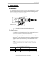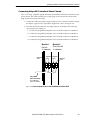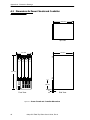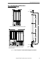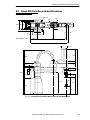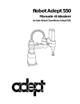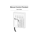
1
Adept 550 Table-Top Robot User’s Guide Including Class 10 Clean Room Version and Adept PA-4 Power Chassis ® Adept 550 Table-Top Robot User’s Guide Including Class 10 Clean Room Version and Adept PA-4 Power Chassis ® Part Number 00554-00030, Rev A April 1995 ® 150 Rose Orchard Way • San Jose, CA 95134 • USA • Phone (408) 432-0888 • Fax (408) 432-8707 Otto-Hahn-Strasse 23 • 44227 Dortmund • Germany • Phone 0231/75 89 40 • Fax 0231/75 89 450 adept technology, inc. 11, Voie la Cardon • 91126 • Palaiseau • France • Phone (1) 69.19.16.16 • Fax (1) 69.32.04.62 1-2, Aza Nakahara, Mitsuya-Cho • Toyohashi-Shi 441-31 • Japan • (0532) 65-2391 • Fax (0532) 65-2390 The information contained herein is the property of Adept Technology, Inc., and shall not be reproduced in whole or in part without prior written approval of Adept Technology, Inc. The information herein is subject to change without notice and should not be construed as a commitment by Adept Technology, Inc. This manual is periodically reviewed and revised. Adept Technology, Inc., assumes no responsibility for any errors or omissions in this document. Critical evaluation of this manual by the user is welcomed. Your comments assist us in preparation of future documentation. A form is provided at the back of the book for submitting your comments. Copyright 1994, 1995 by Adept Technology, Inc. All rights reserved. The Adept logo is a registered trademark of Adept Technology, Inc. Adept, AdeptOne, AdeptOne-MV, AdeptThree, PackOne, HyperDrive, Adept 550, Adept 550 CleanRoom, Adept 1850, Adept 1850XP, A-Series, S-Series, Adept MC, Adept CC, Adept IC, Adept OC, Adept MV, AdeptVision, VisionWare, AdeptMotion, MotionWare, PalletWare, AIM, AdeptNet, AdeptForce, AdeptModules, and V+ are trademarks of Adept Technology, Inc. Any trademarks from other companies used in this publication are the property of those respective companies. Printed in the United States of America Table of Contents 1 General Information. . . . . . . . . . . . . . . . . . . . . . . . . . . . . . . . . . . . . . . . . . 1 1.1 How to Use This Manual . . . . . . . . . . . . . . . . . . . . . . . . . . . . . . . . . . . . . . . . . . . . . 2 Follow These Steps to Install and Configure the Adept 550 Robot . . . . . . . Related Manuals . . . . . . . . . . . . . . . . . . . . . . . . . . . . . . . . . . . . . . . . . . . . . . . . Standard Manuals. . . . . . . . . . . . . . . . . . . . . . . . . . . . . . . . . . . . . . . . . Other Adept Product Manuals . . . . . . . . . . . . . . . . . . . . . . . . . . . . . . Optional V+ Developer’s Manuals . . . . . . . . . . . . . . . . . . . . . . . . . . . .2 .2 .2 .3 .3 1.2 Warnings, Cautions, and Notes . . . . . . . . . . . . . . . . . . . . . . . . . . . . . . . . . . . . . . . 4 1.3 Safety . . . . . . . . . . . . . . . . . . . . . . . . . . . . . . . . . . . . . . . . . . . . . . . . . . . . . . . . . . . . 4 Reading and Training for Users and Operators . . . . . . . . . . . . . . . . . . . . . . . .4 System Safeguards. . . . . . . . . . . . . . . . . . . . . . . . . . . . . . . . . . . . . . . . . . . . . . . .5 Safety Features on External VME Front Panel (VFP) . . . . . . . . . . . . . .5 Computer-Controlled Robots and Motion Devices . . . . . . . . . . . . . .5 Manually-Controlled Robots and Motion Devices . . . . . . . . . . . . . . .5 Other Computer-Controlled Devices . . . . . . . . . . . . . . . . . . . . . . . . . .5 1.4 Robot Modifications . . . . . . . . . . . . . . . . . . . . . . . . . . . . . . . . . . . . . . . . . . . . . . . . 6 Acceptable Modifications . . . . . . . . . . . . . . . . . . . . . . . . . . . . . . . . . . . . . . . . .6 Unacceptable Modifications . . . . . . . . . . . . . . . . . . . . . . . . . . . . . . . . . . . . . . .6 1.5 How Can I Get Help? . . . . . . . . . . . . . . . . . . . . . . . . . . . . . . . . . . . . . . . . . . . . . . . 7 Within the Continental United States. . . . . . . . . . . . . . . . . . . . . . . . . . . . . . . . .7 Service Calls. . . . . . . . . . . . . . . . . . . . . . . . . . . . . . . . . . . . . . . . . . . . . . .7 Application Questions . . . . . . . . . . . . . . . . . . . . . . . . . . . . . . . . . . . . . .7 Applications Internet E-Mail Address . . . . . . . . . . . . . . . . . . . . . . . . . .7 Training Information . . . . . . . . . . . . . . . . . . . . . . . . . . . . . . . . . . . . . . . .7 Within Europe . . . . . . . . . . . . . . . . . . . . . . . . . . . . . . . . . . . . . . . . . . . . . . . . . . . .7 France . . . . . . . . . . . . . . . . . . . . . . . . . . . . . . . . . . . . . . . . . . . . . . . . . . .7 Outside Continental United States or Europe. . . . . . . . . . . . . . . . . . . . . . . . . .8 Adept Bulletin Board Service (BBS) . . . . . . . . . . . . . . . . . . . . . . . . . . . . . . . . . .8 2 Robot Overview . . . . . . . . . . . . . . . . . . . . . . . . . . . . . . . . . . . . . . . . . . . . . 9 2.1 Overview . . . . . . . . . . . . . . . . . . . . . . . . . . . . . . . . . . . . . . . . . . . . . . . . . . . . . . . . 10 2.2 Adept 550 Robot . . . . . . . . . . . . . . . . . . . . . . . . . . . . . . . . . . . . . . . . . . . . . . . . . . 10 General Description. . . . Joint Motions. . . . . . . . . . Joint 1 . . . . . . . . . Joint 2 . . . . . . . . . Joint 3 . . . . . . . . . Joint 4 . . . . . . . . . .............. .............. .............. .............. .............. .............. .............. .............. .............. .............. .............. .............. Adept 550 Table-Top Robot User’s Guide, Rev A . . . . . . . . . . . . . .10 . . . . . . . . . . . . . .10 . . . . . . . . . . . . . .10 . . . . . . . . . . . . . .12 . . . . . . . . . . . . . .13 . . . . . . . . . . . . . .13 iii Table of Contents Robot Working Envelope . . . . . . . . . . . . . . . . . . . . . . . . . . . . . . . . . . . . . . . . . 15 Specifications . . . . . . . . . . . . . . . . . . . . . . . . . . . . . . . . . . . . . . . . . . . . . . . . . . 16 Options . . . . . . . . . . . . . . . . . . . . . . . . . . . . . . . . . . . . . . . . . . . . . . . . . . . . . . . . 17 3 Power Chassis/Controller Overview . . . . . . . . . . . . . . . . . . . . . . . . . . . . 19 3.1 Adept PA-4 Power Chassis . . . . . . . . . . . . . . . . . . . . . . . . . . . . . . . . . . . . . . . . . . 20 Introduction . . . . . . . . . . . . . . . . . . . . . . . . . . . . . . . . . . . . . . . . . . . . . . . . . . . . 20 Dimensions . . . . . . . . . . . . . . . . . . . . . . . . . . . . . . . . . . . . . . . . . . . . . . . . . . . . . 20 3.2 Dual B5 Amplifier Module . . . . . . . . . . . . . . . . . . . . . . . . . . . . . . . . . . . . . . . . . . . 21 Connectors and Indicators . . . . . . . . . . . . . . . . . . . . . . . . . . . . . . . . . . . . . . . 21 3.3 Adept MV Controller . . . . . . . . . . . . . . . . . . . . . . . . . . . . . . . . . . . . . . . . . . . . . . . 22 4 Robot Installation. . . . . . . . . . . . . . . . . . . . . . . . . . . . . . . . . . . . . . . . . . . . 23 4.1 Environmental and Facility Requirements . . . . . . . . . . . . . . . . . . . . . . . . . . . . . . 24 Facility Ambient Air Quality . . . . . . . . . . . . . . . . . . . . . . . . . . . . . . . . . . . . . . . 24 Robot Workcell Free Space . . . . . . . . . . . . . . . . . . . . . . . . . . . . . . . . . . . . . . . 24 4.2 Unpacking and Inspecting . . . . . . . . . . . . . . . . . . . . . . . . . . . . . . . . . . . . . . . . . . 24 Before Unpacking . . . . . . . . . . . . . . . . . . . . . . . . . . . . . . . . . . . . . . . . . . . . . . . 24 After Unpacking . . . . . . . . . . . . . . . . . . . . . . . . . . . . . . . . . . . . . . . . . . . . . . . . 24 Repacking for Relocation . . . . . . . . . . . . . . . . . . . . . . . . . . . . . . . . . . . . . . . . 24 4.3 Robot Mounting . . . . . . . . . . . . . . . . . . . . . . . . . . . . . . . . . . . . . . . . . . . . . . . . . . . 25 Mounting Surface . . . . . . . . . . . . . . . . . . . . . . . . . . . . . . . . . . . . . . . . . . . . . . . 25 Mounting Procedure . . . . . . . . . . . . . . . . . . . . . . . . . . . . . . . . . . . . . . . . . . . . 25 4.4 User Flange Dimensions. . . . . . . . . . . . . . . . . . . . . . . . . . . . . . . . . . . . . . . . . . . . . 26 4.5 End-Effectors. . . . . . . . . . . . . . . . . . . . . . . . . . . . . . . . . . . . . . . . . . . . . . . . . . . . . . 27 4.6 User Connections . . . . . . . . . . . . . . . . . . . . . . . . . . . . . . . . . . . . . . . . . . . . . . . . . . 28 User Air Lines . . . . . . . . . . . . . . . . . . . . . . . . . . . . . . . . . . . . . . . . . . . . . . . . . . . 28 User Electrical Lines . . . . . . . . . . . . . . . . . . . . . . . . . . . . . . . . . . . . . . . . . . . . . . 28 5 Power Chassis Installation . . . . . . . . . . . . . . . . . . . . . . . . . . . . . . . . . . . . 29 5.1 Environmental and Facility Requirements . . . . . . . . . . . . . . . . . . . . . . . . . . . . . . 30 Ambient Air Quality. . . . . . . . . . . . . . . . . . . . . . . . . . . . . . . . . . . . . . . . . . . . . . 30 5.2 Power Chassis Installation . . . . . . . . . . . . . . . . . . . . . . . . . . . . . . . . . . . . . . . . . . . 30 Power Chassis Models . . . . . . . . . . . . . . . . . . . . . . . . . . . . . . . . . . . . . . . . . . . 30 Connecting to AC Power, Model 3303 Power Chassis. . . . . . . . . . . . . . . . . 30 Power Requirements for Model 3303 Power Chassis . . . . . . . . . . . . 30 Connecting Power Cord, Model 3303 Power Chassis . . . . . . . . . . . 31 Connecting to AC Power, Model 3306 Power Chassis. . . . . . . . . . . . . . . . . 32 Power Requirements for Model 3306 Power Chassis . . . . . . . . . . . . 32 Changing Voltage Setting (Model 3306 only) . . . . . . . . . . . . . . . . . 32 Connecting AC Power Cord, Model 3306 Power Chassis . . . . . . . 33 iv Adept 550 Table-Top Robot User’s Guide, Rev A Table of Contents System Grounding Information. . . . . . . . . . . . . . . . . . . . . . . . . . . . . . . . . . . . .33 Circuit Breaker and Fuse Information . . . . . . . . . . . . . . . . . . . . . . . . . . . . . . .34 Chassis Circuit Breaker . . . . . . . . . . . . . . . . . . . . . . . . . . . . . . . . . . . . .34 Chassis Fuses . . . . . . . . . . . . . . . . . . . . . . . . . . . . . . . . . . . . . . . . . . . . .34 Amplifier Module Fuses. . . . . . . . . . . . . . . . . . . . . . . . . . . . . . . . . . . . .34 Joining an Adept PA-4 Power Chassis to an Adept MV Controller . . . . . . .34 Joining at the Top . . . . . . . . . . . . . . . . . . . . . . . . . . . . . . . . . . . . . . . . .35 Joining at the Bottom . . . . . . . . . . . . . . . . . . . . . . . . . . . . . . . . . . . . . .36 Installation in a Rack or Panel Mount . . . . . . . . . . . . . . . . . . . . . . . . . . . . . . .37 Space Around the Chassis. . . . . . . . . . . . . . . . . . . . . . . . . . . . . . . . . .37 Panel Mounting . . . . . . . . . . . . . . . . . . . . . . . . . . . . . . . . . . . . . . . . . . .37 Rack Mounting . . . . . . . . . . . . . . . . . . . . . . . . . . . . . . . . . . . . . . . . . . .37 Removing and Installing Amplifier Modules . . . . . . . . . . . . . . . . . . . . . . . . . .39 Removing Amplifier Modules . . . . . . . . . . . . . . . . . . . . . . . . . . . . . . . . . . . . . .39 Installing Amplifier Modules. . . . . . . . . . . . . . . . . . . . . . . . . . . . . . . . . . . . . . . .39 5.3 Installing Cables: Robot/Controller/Power Chassis . . . . . . . . . . . . . . . . . . . . . . 40 System Cable Connections . . . . . . . . . . . . . . . . . . . . . . . . . . . . . . . . . . . . . . .40 Connecting Adept 550 Robot to Power Chassis . . . . . . . . . . . . . . . . . . . . . .41 Connecting Robot to Adept MV Controller . . . . . . . . . . . . . . . . . . . . . . . . . .44 Connecting Adept MV Controller to Power Chassis . . . . . . . . . . . . . . . . . . .45 6 Operation . . . . . . . . . . . . . . . . . . . . . . . . . . . . . . . . . . . . . . . . . . . . . . . . . 47 6.1 Verify Installation . . . . . . . . . . . . . . . . . . . . . . . . . . . . . . . . . . . . . . . . . . . . . . . . . . 48 Physical Connections . . . . . . . . . . . . . . . . . . . . . . . . . . . . . . . . . . . . . . . . . . . .48 6.2 Turn On Controller and Power Chassis . . . . . . . . . . . . . . . . . . . . . . . . . . . . . . . . 48 6.3 Calibrate Robot . . . . . . . . . . . . . . . . . . . . . . . . . . . . . . . . . . . . . . . . . . . . . . . . . . . 48 About Calibration . . . . . . . . . . . . . . . . . . . . . . . . . . . . . . . . . . . . . . . . . . . . . . .49 6.4 Learning to Operate and Program the Adept 550 Robot . . . . . . . . . . . . . . . . . 49 6.5 Limiting Joint Travel . . . . . . . . . . . . . . . . . . . . . . . . . . . . . . . . . . . . . . . . . . . . . . . . 50 Softstops . . . . . . . . . . . . . . . . . . . . . . . . . . . . . . . . . . . . . . . . . . . . . . . . . . . . . . .50 Hardstops . . . . . . . . . . . . . . . . . . . . . . . . . . . . . . . . . . . . . . . . . . . . . . . . . . . . . .50 6.6 Brakes. . . . . . . . . . . . . . . . . . . . . . . . . . . . . . . . . . . . . . . . . . . . . . . . . . . . . . . . . . . 51 Brake Release Button. . . . . . . . . . . . . . . . . . . . . . . . . . . . . . . . . . . . . . . . . . . . .51 7 Maintenance . . . . . . . . . . . . . . . . . . . . . . . . . . . . . . . . . . . . . . . . . . . . . . 53 7.1 Maintenance Schedule . . . . . . . . . . . . . . . . . . . . . . . . . . . . . . . . . . . . . . . . . . . . 54 7.2 Checking Mounting Bolts and Leveling . . . . . . . . . . . . . . . . . . . . . . . . . . . . . . . 54 7.3 Lubricate Joint 3 Ball Screw . . . . . . . . . . . . . . . . . . . . . . . . . . . . . . . . . . . . . . . . . 54 7.4 Check Tension and Wear On J3 and J4 Drive Belts . . . . . . . . . . . . . . . . . . . . . . 55 7.5 Adept PA-4 Power Chassis . . . . . . . . . . . . . . . . . . . . . . . . . . . . . . . . . . . . . . . . . . 59 Fan Filter Inspection and Cleaning . . . . . . . . . . . . . . . . . . . . . . . . . . . . . . . . .59 Adept 550 Table-Top Robot User’s Guide, Rev A v Table of Contents A Dimension Drawings . . . . . . . . . . . . . . . . . . . . . . . . . . . . . . . . . . . . . . . . 61 A.1 Dimensions for Adept 550 Robot . . . . . . . . . . . . . . . . . . . . . . . . . . . . . . . . . . . . . 62 A.2 Dimensions for Adept PA-4 Power Chassis . . . . . . . . . . . . . . . . . . . . . . . . . . . . . 63 A.3 Dimensions for Power Chassis and Controller . . . . . . . . . . . . . . . . . . . . . . . . . . 64 A.4 Mounting Bracket Dimensions . . . . . . . . . . . . . . . . . . . . . . . . . . . . . . . . . . . . . . . 65 B Adept 550 CleanRoom Robot . . . . . . . . . . . . . . . . . . . . . . . . . . . . . . . . . 67 B.1 Introduction . . . . . . . . . . . . . . . . . . . . . . . . . . . . . . . . . . . . . . . . . . . . . . . . . . . . . . 68 Vacuum Specifications . . . . . . . . . . . . . . . . . . . . . . . . . . . . . . . . . . . . . . . . . . 68 B.2 Installation . . . . . . . . . . . . . . . . . . . . . . . . . . . . . . . . . . . . . . . . . . . . . . . . . . . . . . . 68 B.3 Adept 550 CleanRoom Robot Dimensions . . . . . . . . . . . . . . . . . . . . . . . . . . . . . 69 C Dual Adept 550 Robots . . . . . . . . . . . . . . . . . . . . . . . . . . . . . . . . . . . . . . 71 C.1 Introduction . . . . . . . . . . . . . . . . . . . . . . . . . . . . . . . . . . . . . . . . . . . . . . . . . . . . . . 72 Dual Adept 550 Robot System Description . . . . . . . . . . . . . . . . . . . . . . . . . . 72 C.2 Installation . . . . . . . . . . . . . . . . . . . . . . . . . . . . . . . . . . . . . . . . . . . . . . . . . . . . . . . 72 VMEbus Address for VJI Module . . . . . . . . . . . . . . . . . . . . . . . . . . . . . . . . . . . 72 Adept PA-4 Power Chassis. . . . . . . . . . . . . . . . . . . . . . . . . . . . . . . . . . . . . . . . 72 Cable Installation (Model 3303, with two power chassis) . . . . . . . . . . . . . . 73 C.3 Operation with the Manual Control Pendant (MCP) . . . . . . . . . . . . . . . . . . . . . 73 C.4 Programming Information . . . . . . . . . . . . . . . . . . . . . . . . . . . . . . . . . . . . . . . . . . 73 V+ Language Programming . . . . . . . . . . . . . . . . . . . . . . . . . . . . . . . . . . . . . . 73 V+ Monitor Commands . . . . . . . . . . . . . . . . . . . . . . . . . . . . . . . . . . . . . . . . . . 73 C.5 Emergency Stop Circuit Shuts Off Both Robots . . . . . . . . . . . . . . . . . . . . . . . . . . 74 List of Figures Figure 2-1 Adept 550 Robot Joint Locations . . . . . . . . . . . . . . . . . . . . . . . . . . . . . . . . . . . . 11 Figure 2-2 Joint 1 Motion . . . . . . . . . . . . . . . . . . . . . . . . . . . . . . . . . . . . . . . . . . . . . . . . . . . . 12 Figure 2-3 Robot LEFTY and RIGHTY Configurations . . . . . . . . . . . . . . . . . . . . . . . . . . . . . . 13 Figure 2-4 Joint 3 and Joint 4 Motion . . . . . . . . . . . . . . . . . . . . . . . . . . . . . . . . . . . . . . . . . . 14 Figure 2-5 Adept 550 Robot Working Envelope . . . . . . . . . . . . . . . . . . . . . . . . . . . . . . . . . 15 Figure 3-1 Adept PA-4 Power Chassis . . . . . . . . . . . . . . . . . . . . . . . . . . . . . . . . . . . . . . . . . 20 Figure 3-2 Adept MV-8 Controller . . . . . . . . . . . . . . . . . . . . . . . . . . . . . . . . . . . . . . . . . . . . 22 Figure 4-1 Mounting Hole Pattern (Robot-to-Mounting Surface) . . . . . . . . . . . . . . . . . . . 25 Figure 4-2 User Flange Dimensions . . . . . . . . . . . . . . . . . . . . . . . . . . . . . . . . . . . . . . . . . . . . 26 Figure 4-3 User Flange Close-up Dimensions. . . . . . . . . . . . . . . . . . . . . . . . . . . . . . . . . . . . 27 Figure 5-1 Power Entry Module on Adept PA-4 Chassis (Model 3303). . . . . . . . . . . . . . . 31 vi Adept 550 Table-Top Robot User’s Guide, Rev A Table of Contents Figure 5-2 Joining the Power Chassis and Controller at the Top . . . . . . . . . . . . . . . . . . . .35 Figure 5-3 Joining the Power Chassis and Controller at the Bottom. . . . . . . . . . . . . . . . .36 Figure 5-4 Installing Mounting Brackets . . . . . . . . . . . . . . . . . . . . . . . . . . . . . . . . . . . . . . . .38 Figure 5-5 Adept 550 System Cable Installation . . . . . . . . . . . . . . . . . . . . . . . . . . . . . . . . .40 Figure 5-6 Adept 550 Robot Back Plate and Ground Connections . . . . . . . . . . . . . . . . .42 Figure 5-7 Amplifier Modules 1 and 2 in Power Chassis, Model 3303 . . . . . . . . . . . . . . . .43 Figure 5-8 Robot to VJI Cable Installation . . . . . . . . . . . . . . . . . . . . . . . . . . . . . . . . . . . . . .44 Figure 5-9 Power Chassis to VJI Cable Installation, Model 3303 . . . . . . . . . . . . . . . . . . . .45 Figure 7-1 Lubrication of Joint 3 Ball Screw . . . . . . . . . . . . . . . . . . . . . . . . . . . . . . . . . . . . .55 Figure 7-2 Location of Access Cover on Underside of Outer Link. . . . . . . . . . . . . . . . . . .56 Figure 7-3 Location of Joint 3 and Joint 4 Drive Belts . . . . . . . . . . . . . . . . . . . . . . . . . . . . .57 Figure 7-4 Close-up View of Joint 3 Brake Assembly. . . . . . . . . . . . . . . . . . . . . . . . . . . . . .58 Figure A-1 Adept 550 Robot Top and Side Dimensions. . . . . . . . . . . . . . . . . . . . . . . . . . . .62 Figure A-2 Adept PA-4 Power Chassis Dimensions. . . . . . . . . . . . . . . . . . . . . . . . . . . . . . . .63 Figure A-3 Power Chassis and Controller Dimensions . . . . . . . . . . . . . . . . . . . . . . . . . . . . .64 Figure A-4 Power Chassis and Controller with Mounting Brackets Installed . . . . . . . . . . .65 Figure B-1 Adept 550 CleanRoom Robot Top and Side Dimensions. . . . . . . . . . . . . . . . .69 List of Tables Table 2-1 Specifications . . . . . . . . . . . . . . . . . . . . . . . . . . . . . . . . . . . . . . . . . . . . . . . . . . . .16 Table 4-1 Mounting Bolt Specifications . . . . . . . . . . . . . . . . . . . . . . . . . . . . . . . . . . . . . . . .25 Table 5-1 Adept PA-4 Power Chassis Model 3303 Power Requirements . . . . . . . . . . . . .30 Table 5-2 Adept PA-4 Power Chassis Model 3306 Power Requirements . . . . . . . . . . . .32 Table 5-3 AC Power Cord Specifications, Model 3306 Power Chassis . . . . . . . . . . . . . .33 Table 6-1 Softstop and Hardstop Specifications . . . . . . . . . . . . . . . . . . . . . . . . . . . . . . . .50 Table 7-1 Inspection and Maintenance . . . . . . . . . . . . . . . . . . . . . . . . . . . . . . . . . . . . . . .54 Table B-1 Adept 550 CleanRoom Robot Vacuum Specifications . . . . . . . . . . . . . . . . . .68 Table C-1 Typical Robot-VJI-Amplifier Assignments in Dual Adept 550 Robot System . .73 Adept 550 Table-Top Robot User’s Guide, Rev A vii General Information 1 1.1 How to Use This Manual . . . . . . . . . . . . . . . . . . . . . . . . . . . . . . . . . . . . . . . . . . . . . 2 Follow These Steps to Install and Configure the Adept 550 Robot . . . . . . . Related Manuals . . . . . . . . . . . . . . . . . . . . . . . . . . . . . . . . . . . . . . . . . . . . . . . . Standard Manuals. . . . . . . . . . . . . . . . . . . . . . . . . . . . . . . . . . . . . . . . . Other Adept Product Manuals . . . . . . . . . . . . . . . . . . . . . . . . . . . . . . Optional V+ Developer’s Manuals . . . . . . . . . . . . . . . . . . . . . . . . . . . .2 .2 .2 .3 .3 1.2 Warnings, Cautions, and Notes . . . . . . . . . . . . . . . . . . . . . . . . . . . . . . . . . . . . . . . 4 1.3 Safety . . . . . . . . . . . . . . . . . . . . . . . . . . . . . . . . . . . . . . . . . . . . . . . . . . . . . . . . . . . . 4 Reading and Training for Users and Operators . . . . . . . . . . . . . . . . . . . . . . . .4 System Safeguards. . . . . . . . . . . . . . . . . . . . . . . . . . . . . . . . . . . . . . . . . . . . . . . .5 Safety Features on External VME Front Panel (VFP) . . . . . . . . . . . . . .5 Computer-Controlled Robots and Motion Devices . . . . . . . . . . . . . .5 Manually-Controlled Robots and Motion Devices . . . . . . . . . . . . . . .5 Other Computer-Controlled Devices . . . . . . . . . . . . . . . . . . . . . . . . . .5 1.4 Robot Modifications . . . . . . . . . . . . . . . . . . . . . . . . . . . . . . . . . . . . . . . . . . . . . . . . 6 Acceptable Modifications . . . . . . . . . . . . . . . . . . . . . . . . . . . . . . . . . . . . . . . . .6 Unacceptable Modifications . . . . . . . . . . . . . . . . . . . . . . . . . . . . . . . . . . . . . . .6 1.5 How Can I Get Help? . . . . . . . . . . . . . . . . . . . . . . . . . . . . . . . . . . . . . . . . . . . . . . . 7 Within the Continental United States. . . . . . . . . . . . . . . . . . . . . . . . . . . . . . . . .7 Service Calls. . . . . . . . . . . . . . . . . . . . . . . . . . . . . . . . . . . . . . . . . . . . . . .7 Application Questions . . . . . . . . . . . . . . . . . . . . . . . . . . . . . . . . . . . . . .7 Applications Internet E-Mail Address . . . . . . . . . . . . . . . . . . . . . . . . . .7 Training Information . . . . . . . . . . . . . . . . . . . . . . . . . . . . . . . . . . . . . . . .7 Within Europe . . . . . . . . . . . . . . . . . . . . . . . . . . . . . . . . . . . . . . . . . . . . . . . . . . . .7 France . . . . . . . . . . . . . . . . . . . . . . . . . . . . . . . . . . . . . . . . . . . . . . . . . . .7 Outside Continental United States or Europe. . . . . . . . . . . . . . . . . . . . . . . . . .8 Adept Bulletin Board Service (BBS) . . . . . . . . . . . . . . . . . . . . . . . . . . . . . . . . . .8 Adept 550 Table-Top Robot User’s Guide, Rev A 1 Chapter 1 - General Information 1.1 How to Use This Manual Follow These Steps to Install and Configure the Adept 550 Robot 1. Read Chapter 1 to learn about Safety and Customer Service issues. 2. Read Chapter 2 to get an overview of the Adept 550 Robot and Chapter 3 for an overview of the Adept PA-4 power chassis. 3. Read Chapter 4 to learn the steps in installing the robot. 4. Read Chapter 5 to learn the steps in installing the power chassis and connecting cables between all components. 5. Read Chapter 6 to find out how to turn on the system and where to find programming information. 6. Read Chapter 7 for periodic maintenance for the system. 7. Read Appendix A for dimension information, Appendix B for CleanRoom information, and Appendix C for Dual Adept 550 robot information. Related Manuals Adept products come with a set of documentation that is defined by the products you have ordered. In addition, there are optional manuals available if you are going to be programming the Adept system. This manual refers to both the standard and optional manuals. The following sections give a brief description of the contents and organization of the Adept documentation set. Standard Manuals In addition to this Adept 550 Table-Top Robot User’s Guide the following manuals are shipped with the system: 2 Manual Material Covered Adept MV Controller User's Guide This manual details the installation, configuration, and maintenance of your Adept controller. V+ Operating System User’s Guide A description of the V+ operating system. Loading, storing, and executing programs is covered in this manual. Instructions for Adept Utility Programs Adept provides a series of programs for configuring and calibrating various features of your Adept system. These utility programs are described in this manual. V+ Release Notes Descriptions of the changes to V+. This document is updated as each version of V+ is released. Adept 550 Table-Top Robot User’s Guide, Rev A How to Use This Manual Other Adept Product Manuals When you order AdeptVision VME, AdeptMotion VME, AdeptForce VME, or any AIM software product, you will receive manuals that cover those products. Also, optional hardware such as the Manual Control Pendant will come with a manual. A partial list is shown below. Manual Material Covered AdeptVision VME User's Guide Concepts and strategies for programming the AdeptVision VME system. (see also the optional AdeptVision Reference Guide below) AdeptMotion VME User’s Guide Installation, configuration, and tuning of an AdeptMotion VME system. AdeptForce VME User’s Guide Installation, operation, and programming of the AdeptForce VME product. Manual Control Pendant User’s Guide Basic use and programming of the manual control pendant. Optional V+ Developer’s Manuals If you will be programming V+ applications, you should order the optional V+ developer ’s manuals (first three in the list below). These manuals contain a complete description of the commands, instructions, functions, and other features available in the V+ language and operating system. These manuals are essential for advanced applications programming. If you will be programming vision applications, you should order the AdeptVision Reference Guide (in addition to the V+ developer’s manuals). Manual Material Covered V+ Operating System Reference Guide Descriptions of the V+ operating system commands (known as monitor commands). V+ Language User’s Guide V+ is a complete high-level language as well as an operating system. This manual covers programming principles for creating V+ programs. V+ Language Reference Guide A complete description of the keywords in the basic V+ language system. AdeptVision Reference Guide Descriptions of the additional V + keywords available with the AdeptVision VME option. Adept 550 Table-Top Robot User’s Guide, Rev A 3 Chapter 1 - General Information 1.2 Warnings, Cautions, and Notes There are three levels of special notation used in this manual. They are: WARNING: Injury or major equipment damage could result if the actions indicated in a “WARNING” are not complied with. A warning statement typically describes the hazard, its possible effect, and the measures that must be taken to reduce the hazard. ! CAUTION: Damage to your equipment could result if the action specified in the “CAUTION” is not complied with. NOTE: A “NOTE” provides supplementary information, emphasizes a point or procedure, or gives a tip for easier operation. 1.3 Safety Reading and Training for Users and Operators Adept systems can include computer-controlled mechanisms that are capable of moving at high speeds and exerting considerable force. Like all robot and motion systems, and most industrial equipment, they must be treated with respect by the user and the operator. This manual should be read by all personnel who operate or maintain Adept systems, or who work within or near the workcell. We also recommend you read the American National Standard for Industrial Robot Systems Safety Requirements, published by the Robotic Industries Association(RIA), in conjunction with the American National Standards Institute. The publication, ANSI/RIA R15.06 1992, contains guidelines for robot system installation, safeguarding, maintenance, testing, start-up, and operator training. The document is available from the American National Standards Institute, 11 West 42nd Street, #13THF, New York, NY 10036-8002. This manual assumes that the user has attended an Adept training course and has a basic working knowledge of the system. The user should provide the necessary additional training for all personnel who will be working with the system. There may be warnings in Adept manuals that specify only skilled or instructed persons should attempt certain procedures. These are defined as: • Skilled persons have technical knowledge or sufficient experience to enable them to avoid the dangers which electricity may create (engineers and technicians). • Instructed persons are adequately advised or supervised by skilled persons to enable them to avoid the dangers which electricity may create (operating and maintenance staff). 4 Adept 550 Table-Top Robot User’s Guide, Rev A Safety System Safeguards Safeguards should be an integral part of robot or motion workcell design, installation, operator training, and operating procedures. Adept systems have various communication features to aid in constructing system safeguards. These include the emergency stop circuitry and digital input and output lines. These features are described in the Adept MV Controller User's Guide. Safety Features on External VME Front Panel (VFP) On the Adept MV controller, the optional external VME Front Panel (VFP) has three important safety features, the HIGH POWER and PROGRAM RUNNING indicators, and the EMERGENCY STOP switch. If you choose not to use the VFP, you should provide similar safety features by using the Front Panel/MCP and Digital I/O connectors on the System I/O module. Refer to the Adept MV Controller User's Guide for more information, or call Adept Customer Service. WARNING: Entering the workcell when either the HIGH POWER or the PROGRAM RUNNING light is on can result in severe injury. This warning applies to each of the next three sections. Computer-Controlled Robots and Motion Devices Adept systems are computer controlled, and the program that is currently running the robot or motion device may cause it to move at times or along paths you may not anticipate. When the HIGH POWER light and the PROGRAM RUNNING light on the optional VFP are illuminated, do not enter the workcell because the robot or motion device might move unexpectedly. (The LAMP TEST button on the VFP allows these lights to be periodically checked.) Manually-Controlled Robots and Motion Devices Adept robots and other motion devices can also be controlled manually when the HIGH POWER light on the VFP is illuminated. When this light is lit, motion can be initiated from the system keyboard or from the optional Manual Control Pendant (MCP). If you have to enter the workcell when this light is lit, press the MAN/HALT button on the MCP. This will prevent anyone else from initiating unexpected motion from the system keyboard. Other Computer-Controlled Devices In addition, Adept systems can be programmed to control equipment or devices other than the robot or main motion device. The program controlling these other devices may cause them to operate unexpectedly. Make sure that safeguards are in place to prevent personnel from entering the workcell when a program is running. Adept Technology highly recommends the use of additional safety features such as light curtains, safety gates, or safety floor mats to prevent entry to the workcell while HIGH POWER is enabled. These devices can be connected using the emergency stop circuitry. Adept 550 Table-Top Robot User’s Guide, Rev A 5 Chapter 1 - General Information 1.4 Robot Modifications It is often necessary to make modifications to Adept robots to successfully integrate them into a workcell. Unfortunately, many seemingly simple modifications can either cause a robot failure, or reduce the robot’s performance, reliability, or lifetime. Acceptable Modifications In general, the following robot modifications will not cause any problems, but may affect robot performance: • Attaching tooling, utility boxes, solenoid packs, vacuum pumps, screwdrivers, cameras, lighting, etc. to the inner link, outer link, or column. Any loads attached to the moving robot parts must be considered part of the payload. • Attaching hoses, pneumatic lines, or cables to the robot. These should be designed so they do not restrict joint motion or cause robot motion errors. • Modifying robot access covers as long as adequate protection is provided after the modification. Unacceptable Modifications If not done properly, the modifications listed below will damage the robot, reduce system reliability, or shorten the life of the robot. ! CAUTION: Making any of the modifications outlined below will void the warranty of any components that Adept determines were damaged due to the modification. Please contact Adept Customer Service before attempting any of the following modifications to determine if they can be made without causing problems. • Modifying any of the robot harnesses or robot to controller cables. • Modifying any drive system components. • Modifying, including drilling or cutting, any robot casting. • Modifying any robot electrical component or PC board other than those explicitly stated in the robot user’s guide. • Routing additional hoses, air lines, or wires through the robot. 6 Adept 550 Table-Top Robot User’s Guide, Rev A How Can I Get Help? 1.5 How Can I Get Help? Within the Continental United States Adept Technology maintains a Customer Service Center at its headquarters in San Jose, CA. The phone numbers are: Service Calls (800) 232-3378 (24 hours per day, 7 days a week) (408) 433-9462 FAX Application Questions (800) 232-3378 (Monday to Friday, 8:00 a.m. to 5:00 p.m., Pacific time) (408) 434-6248 FAX Applications Internet E-Mail Address If you have access to the Internet, you can send applications questions by e-mail to: [email protected] This method also enables you to attach a file, such as a portion of V+ program code, to your message. Training Information For information regarding Adept Training Courses in the USA, please call (408) 434-5024. Within Europe For European customers outside of France, Adept Technology maintains a Customer Service Center in Dortmund, Germany. The phone numbers are: (49) 231 / 75 89 40 from within Europe (Monday to Friday, 8:00 a.m. to 5:00 p.m., CET) (49) 231/75 89 450 FAX France For customers in France, Adept Technology maintains a Customer Service Center in Paris, France. The phone numbers are: (33) 1 69 19 16 16 (Monday to Friday, 8:30 a.m. to 5:30 p.m., CET) (33) 1 69 32 04 62 FAX Adept 550 Table-Top Robot User’s Guide, Rev A 7 Chapter 1 - General Information Outside Continental United States or Europe For service calls, application questions, and training information, call the Adept customer service center in San Jose, California USA: (408) 434-5000 (408) 433-9462 FAX (service requests) (408) 434-6248 FAX (application questions) NOTE: When calling with a controller related question, please have the serial number of the controller. If your system includes an Adept robot, also have the serial number of the robot. The serial numbers can be determined by using the ID command (see the V+ Operating System User’s Guide) . Adept Bulletin Board Service (BBS) Adept maintains a bulletin board service for Adept customers. Adept posts application hints and utilities to this bulletin board and users may post their own hints and application notes. There is no charge for access to the bulletin board. The BBS number is (203) 264-5590. The first time you call you will be able to set up an account right from the BBS. If you have any questions, call (800) 232-3378 and ask about the BBS. 8 Adept 550 Table-Top Robot User’s Guide, Rev A Robot Overview 2 2.1 Overview . . . . . . . . . . . . . . . . . . . . . . . . . . . . . . . . . . . . . . . . . . . . . . . . . . . . . . . . 10 2.2 Adept 550 Robot . . . . . . . . . . . . . . . . . . . . . . . . . . . . . . . . . . . . . . . . . . . . . . . . . . 10 General Description. . . . . . . . . . . . . . . . . . Joint Motions. . . . . . . . . . . . . . . . . . . . . . . . Joint 1 . . . . . . . . . . . . . . . . . . . . . . . Joint 2 . . . . . . . . . . . . . . . . . . . . . . . Joint 3 . . . . . . . . . . . . . . . . . . . . . . . Joint 4 . . . . . . . . . . . . . . . . . . . . . . . Robot Working Envelope . . . . . . . . . . . . . Specifications . . . . . . . . . . . . . . . . . . . . . . . Options . . . . . . . . . . . . . . . . . . . . . . . . . . . . .............. .............. .............. .............. .............. .............. .............. .............. .............. Adept 550 Table-Top Robot User’s Guide, Rev A . . . . . . . . . . . . . .10 . . . . . . . . . . . . . .10 . . . . . . . . . . . . . .10 . . . . . . . . . . . . . .12 . . . . . . . . . . . . . .13 . . . . . . . . . . . . . .13 . . . . . . . . . . . . . .15 . . . . . . . . . . . . . .16 . . . . . . . . . . . . . .17 9 Chapter 2 - Robot Overview 2.1 Overview The Adept 550 Table-Top Robot system consists of three major components: • the Adept 550 Table-Top Robot • the Adept PA-4 Power Chassis • the Adept MV-8 or MV-19 Controller This chapter gives an overview of the Adept 550 robot. See Chapter 3 for an overview of the Adept PA-4 power chassis. 2.2 Adept 550 Robot General Description The Adept 550 robot is a four-axis SCARA (Selective Compliance Assembly Robot Arm) robot. Joints 1, 2, and 4 are rotational and Joint 3 is translational. See Figure 2-1 for an overview of the robot joint locations, Figure 2-5 for the operating envelope, and Table 2-1 for specifications. Programming and control of the Adept 550 robot is accomplished through the Adept MV Controller. Joint Motions Joint 1 Joint 1, also referred to as the “shoulder,” provides rotation of the inner link. Joint 1 motion is limited to ±100°. See Figure 2-2. 10 Adept 550 Table-Top Robot User’s Guide, Rev A Adept 550 Robot Joint 2 "Elbow" Joint 3 Joint 1 "Shoulder" ® Outer Link Inner Link Joint 4 "Wrist" User Flange Base Figure 2-1. Adept 550 Robot Joint Locations Adept 550 Table-Top Robot User’s Guide, Rev A 11 Chapter 2 - Robot Overview 100° 100° Figure 2-2. Joint 1 Motion Joint 2 Joint 2, also referred to as the “elbow,” provides rotation of the outer link. Joint 2 motion is limited to ±140°. Joint 2’s motion is similar to an elbow capable of acting in both left- and right-hand configurations (see Figure 2-3). When you teach a robot location, the robot elbow (when viewed from the back of the robot) will be pointing either to the left or right. These arm orientations are referred to as “Lefty” and “Righty.” In Figure 2-3, the dotted outline is in a lefty configuration and the solid outline is in a righty configuration. Under program control, the robot will always move to the next location in its current configuration (lefty or righty) unless the location is a “precision point” or the LEFTY or RIGHTY program instruction is used. For further information concerning right- and left-hand configuration, refer to the V+ Language User’s Guide. 12 Adept 550 Table-Top Robot User’s Guide, Rev A Adept 550 Robot Lefty Righty Back of Robot Figure 2-3. Robot LEFTY and RIGHTY Configurations Joint 3 Joint 3 provides vertical translation of the quill. Joint 3 drives the quill to up and down with a maximum stroke of 200 mm (7.9”). See Figure 2-4. The Adept 550 Cleanroom robot has a maximum Joint 3 stroke of 180 mm; see Appendix B. Joint 4 Joint 4, also referred to as the “wrist”, provides for rotation of the quill. Joint 4 does not have hardstops, but software limits its motion to ±180° (see Figure 2-4). Also see Table 6-1 for additional information on Joint 4 softstops. Adept 550 Table-Top Robot User’s Guide, Rev A 13 Chapter 2 - Robot Overview ® Joint 3 Stroke Joint 4 Rotation Figure 2-4. 14 Joint 3 and Joint 4 Motion Adept 550 Table-Top Robot User’s Guide, Rev A Adept 550 Robot Robot Working Envelope Maximum Radial Reach Functional Area 550 mm (21.7") Maximum Intrusion Contact Radius 590 mm (23.3") 100° 100° Minimum Radial Reach 194 mm (7.6") 140° Figure 2-5. Back of Robot 140° Adept 550 Robot Working Envelope NOTE: See Appendix A for robot and power chassis dimension information. Adept 550 Table-Top Robot User’s Guide, Rev A 15 Chapter 2 - Robot Overview Specifications All specifications are subject to change without notice. Table 2-1. Specifications Adept 550 Robot Specifications Reach Maximum radial 550 mm (21.7") Minimum radial 194 mm (7.6") Vertical clearance (bottom of base to end of quill) • with maximum joint 3 retraction • with maximum joint 3 extension 336 mm (13.2") 136 mm (5.3") Vertical Stroke Joint 3 (Z direction) 200 mm (7.9") Joint Rotation Joint 1 ±100° Joint 2 ±140° Joint 4 ±360° Maximum Payload (including end effector and arm-mounted tooling) During operation 5.5 kg (12.1 lb) Inertia Load About Joint 4 axis (maximum) 450 kgcm2 (150 lb-in2) Force Joint 3 downward force (minimum) without payload 12.1 kg (26.6 lb) Cycle Timea 2 kg (4.4 lb) 0.8 seconds Resolution Joint 1 0.0008° per encoder count Joint 2 0.0012° per encoder count Joint 3 (vertical Z) 0.0022 mm per encoder count Joint 4 (tool rotation) 0.0012° per encoder count Repeatability (at constant temperature) X,Y plane ± 0.025 mm (±0.001") Joint 3 (vertical Z) ±0.03 mm (±0.001") Joint 4 (rotational) ±0.05° 16 Adept 550 Table-Top Robot User’s Guide, Rev A Adept 550 Robot Table 2-1. Specifications (Continued) Adept 550 Robot Specifications Maximum Joint Speed (with 2 kg payload) Joint 1 270°/sec Joint 2 430°/sec Joint 3 1000 mm/sec (40"/sec) Joint 4 480°/sec Weight Robot without options approximately 45 kg (100 lb) Power chassis, with two amplifier modules approximately 14.5 kg (32 lb) a The robot tool performs continuous path, straight-line motions 25 mm (1") up, 305 mm (12") over, 25 mm (1") down, and back along the same path. COARSE is enabled and BREAKs are used at each end location. Not achievable over all paths. Options The Adept 550 is compatible with the following Adept options: • AdeptVision VME systems • Robot-mounted camera hardware • Extended robot-to-controller cables (10 m [32.8 ft]) • AdeptForce VME • Adept 550 Class 10 CleanRoom Model available (See Appendix B) • Dual Adept 550 robot systems available (See Appendix C) Adept 550 Table-Top Robot User’s Guide, Rev A 17 Power Chassis/Controller Overview 3 3.1 Adept PA-4 Power Chassis . . . . . . . . . . . . . . . . . . . . . . . . . . . . . . . . . . . . . . . . . . 20 Introduction . . . . . . . . . . . . . . . . . . . . . . . . . . . . . . . . . . . . . . . . . . . . . . . . . . . .20 Dimensions . . . . . . . . . . . . . . . . . . . . . . . . . . . . . . . . . . . . . . . . . . . . . . . . . . . . .20 3.2 Dual B5 Amplifier Module. . . . . . . . . . . . . . . . . . . . . . . . . . . . . . . . . . . . . . . . . . . 21 Connectors and Indicators. . . . . . . . . . . . . . . . . . . . . . . . . . . . . . . . . . . . . . . .21 3.3 Adept MV Controller . . . . . . . . . . . . . . . . . . . . . . . . . . . . . . . . . . . . . . . . . . . . . . . 22 Adept 550 Table-Top Robot User’s Guide, Rev A 19 Chapter 3 - Power Chassis/Controller Overview 3.1 Adept PA-4 Power Chassis Introduction The Adept PA-4 power chassis provides amplified power signals to drive the robot motors in an Adept 550 robot system. The amplifier modules in the Adept PA-4 power chassis receive control signals from the Adept MV controller. The amplifier modules then drive the various robot joint motors at the level commanded by the controller. The Adept PA-4 chassis is cooled by a fan located in the lower front section. Incoming air is cleaned by a reusable filter. AMP-1 AMP-3 AMP-2 AMP-4 DUAL B5 AMP DUAL B5 AMP DO NOT REMOVE OR INSTALL THIS MODULE UNLESS HIGH VOLTS LED IS COMPLETELY EXTINGUISHED. DO NOT REMOVE OR INSTALL THIS MODULE UNLESS HIGH VOLTS LED IS COMPLETELY EXTINGUISHED. HIGH VOLTS ON HIGH VOLTS ON PWM ON PWM ON LOW VOLTS ON DO NOT REMOVE THIS PANEL UNLESS SYSTEM POWER IS OFF AND AMPLIFIER HIGH VOLTS LED(S) IS COMPLETELY EXTINGUISHED. DO NOT OPERATE WITHOUT THIS PANEL INSTALLED. LOW VOLTS ON OPEN CKT FAULT OPEN CKT FAULT HV SAG/OVER TEMP HV SAG/OVER TEMP SHORT FAULT B1 DO NOT REMOVE THIS PANEL UNLESS SYSTEM POWER IS OFF AND AMPLIFIER HIGH VOLTS LED(S) IS COMPLETELY EXTINGUISHED. DO NOT OPERATE WITHOUT THIS PANEL INSTALLED. SHORT FAULT B2 B1 B2 B1 B2 B1 B2 C O N T R O L C O N T R O L C O N T R O L C O N T R O L S I G N A L S I G N A L S I G N A L S I G N A L M O T O R M O T O R P O W E R P O W E R O U T P U T O U T P U T adept technology, inc. OFF ON L1 L2 L3 G Figure 3-1. Adept PA-4 Power Chassis Dimensions For dimensions of the Adept PA-4 power chassis, see Appendix A. 20 Adept 550 Table-Top Robot User’s Guide, Rev A Dual B5 Amplifier Module 3.2 Dual B5 Amplifier Module The Dual B5 Amplifier module is a plug-in module that contains the circuitry and amplifying components to drive two of the motors in an Adept 550 robot. Each Dual B5 amplifier can drive one major axis (J1 or J2) and one minor axis (J3 or J4). In a typical Adept 550 robot system, there are two identical Dual B5 Amplifier modules in the Adept PA-4 power chassis. The amplifier module on the left-hand side, called Module 1, drives motors 1 and 3. The amplifier module on the right-hand side, called Module 2, drives motors 2 and 4. Connectors and Indicators ➊ DUAL B5 AMP Status LEDs. The left-hand column of LEDs is for the first motor controlled by this module; the right-hand column is for the second motor controlled by this module. When an LED is turned on it indicates the following conditions: High Volts On indicates the high voltage to the amps is turned on. DO NOT REMOVE OR INSTALL THIS MODULE UNLESS HIGH VOLTS LED IS COMPLETELY EXTINGUISHED. PWM On indicates that current servo is on. It does not go on until calibration is complete. HIGH VOLTS ON ➊ PWM ON LOW VOLTS ON Low Volts On indicates the low voltage supply in the power chassis is on. OPEN CKT FAULT HV SAG/OVER TEMP SHORT FAULT B1 B2 ➋ B1 B2 C O N T R O L C O N T R O L S I G N A L S I G N A L Open Ckt Fault indicates that an open circuit in the motor leads has been detected. HV Sag/Over Temp indicates that either the input voltage has dropped below the specified level or an over-temperature fault has been detected on an amplifier module. Short Fault indicates that an over-current in the motor leads has been detected. ➋ ➌ M O T O R P O W E R ➌ Control Signal connector – the “VJI to Amp” cable connectors are installed here. See Chapter 5 for more details. Motor Power Output connector – the “motor power” cable is installed here. See Chapter 5 for more details. O U T P U T Adept 550 Table-Top Robot User’s Guide, Rev A 21 Chapter 3 - Power Chassis/Controller Overview 3.3 Adept MV Controller The Adept MV-8 (or MV-19) controller contains the various VME modules that control the robot system and run the V+ Operating System and Programming Language. See the Adept MV Controller User's Guide for information on this product. 030 VGB SIO OK 1 OK 1 2 ESTOP 2 3 ACC V 4 SCSI 3 OK 1 2 3 4 ON 1 2 3 4 5 6 7 8 ON 4 D R I RESET V E A R S 4 2 2 / 4 8 5 VIS F P / M C P V I D E O B U S B U S DIO VJI ES OK V I D E O HPE 1 2 3 4 5 6 FAIL PASS I N P U T S I N P U T S M O N I T O R AMPLIFIER SIGNAL 1 #1 2 3 R S 2 3 2 4 1 2 3 4 R S 2 3 2 ON R S 2 3 2 / T E R M BELT ENCODER O U T P U T S #2 I / O R S 2 3 2 P O I N T E R 2 4 V 1 0 0 m A E T H E R N E T KEYBOARD C A M E R A S / S T R O B E S O U T P U T S ARM SIGNAL ® adept technology, inc. WARNING: FOR CONTINUED PROTECTION AGAINST RISK OF FIRE, REPLACE ONLY WITH SAME TYPE AND RATING OF FUSE. Figure 3-2. 22 Adept MV-8 Controller Adept 550 Table-Top Robot User’s Guide, Rev A Robot Installation 4 4.1 Environmental and Facility Requirements . . . . . . . . . . . . . . . . . . . . . . . . . . . . . 24 Facility Ambient Air Quality. . . . . . . . . . . . . . . . . . . . . . . . . . . . . . . . . . . . . . . .24 Robot Workcell Free Space . . . . . . . . . . . . . . . . . . . . . . . . . . . . . . . . . . . . . . .24 4.2 Unpacking and Inspecting . . . . . . . . . . . . . . . . . . . . . . . . . . . . . . . . . . . . . . . . . 24 Before Unpacking . . . . . . . . . . . . . . . . . . . . . . . . . . . . . . . . . . . . . . . . . . . . . . .24 After Unpacking . . . . . . . . . . . . . . . . . . . . . . . . . . . . . . . . . . . . . . . . . . . . . . . . .24 Repacking for Relocation . . . . . . . . . . . . . . . . . . . . . . . . . . . . . . . . . . . . . . . . .24 4.3 Robot Mounting . . . . . . . . . . . . . . . . . . . . . . . . . . . . . . . . . . . . . . . . . . . . . . . . . . . 25 Mounting Surface . . . . . . . . . . . . . . . . . . . . . . . . . . . . . . . . . . . . . . . . . . . . . . .25 Mounting Procedure . . . . . . . . . . . . . . . . . . . . . . . . . . . . . . . . . . . . . . . . . . . . .25 4.4 User Flange Dimensions . . . . . . . . . . . . . . . . . . . . . . . . . . . . . . . . . . . . . . . . . . . . 26 4.5 End-Effectors . . . . . . . . . . . . . . . . . . . . . . . . . . . . . . . . . . . . . . . . . . . . . . . . . . . . . 27 4.6 User Connections . . . . . . . . . . . . . . . . . . . . . . . . . . . . . . . . . . . . . . . . . . . . . . . . . 28 User Air Lines . . . . . . . . . . . . . . . . . . . . . . . . . . . . . . . . . . . . . . . . . . . . . . . . . . . .28 User Electrical Lines . . . . . . . . . . . . . . . . . . . . . . . . . . . . . . . . . . . . . . . . . . . . . .28 Adept 550 Table-Top Robot User’s Guide, Rev A 23 Chapter 4 - Robot Installation 4.1 Environmental and Facility Requirements Facility Ambient Air Quality Temperature: 5° to 40° C (41° to 104° F) Relative humidity: 5 to 90% non-condensing Robot Workcell Free Space The workcell design should allow the Adept 550 freedom of movement within the area specified in Figure 2-5. Additional allowances maybe required to accommodate any installed end-of-arm tooling. 4.2 Unpacking and Inspecting Before Unpacking Carefully inspect all shipping crates for evidence of damage during transit. Pay special attention to tilt and shock indication labels (if they are present) on the exteriors of the containers. If any damage is indicated, request that the carrier ’s agent be present at the time the container is unpacked. After Unpacking Compare the actual items received (not just the packing slip) with your equipment purchase order and verify that you received everything you ordered. Inspect each item for external damage as it is removed from its container. If any damage is evident, contact Adept at the number listed in Chapter 1. Retain all containers and packaging materials. These items will be necessary to settle damage claims or to relocate the robot. Repacking for Relocation If you relocate the robot, reverse the installation procedures that follow this section. Reuse all original packing containers and materials, and follow all safety notes used for installation. Improper packaging for shipment will void your warranty. ! 24 CAUTION: The Adept 550 robot with the inner and outer links fully extended has a center of gravity beyond its base. If an unmounted Adept 550 is fully extended, it may fall and cause substantial damage. Always fold the links in towards the center if the robot is not mounted. Adept 550 Table-Top Robot User’s Guide, Rev A Robot Mounting 4.3 Robot Mounting Mounting Surface The Adept 550 is designed to be mounted on a smooth, flat, level tabletop. The mounting structure must be rigid enough to prevent vibration and flexing during robot operation. Excessive vibration or mounting flexure will degrade robot performance. Figure 4-1 shows the mounting hole pattern for the Adept 550. 4 x 14 dia. thru 200 160 125 80 All dimensions in mm. 140 40 Figure 4-1. 80 200 Mounting Hole Pattern (Robot-to-Mounting Surface) Mounting Procedure 1. Using the dimensions shown in Figure 4-1, drill and tap the surface for four 7/16 - 14 UNC x 1.50" or a metric size of M12 - 1.75 x 36mm machine bolts (bolts not provided). See Table 4-1 for bolt and torque specifications. 2. Place the robot on the mounting surface and secure it with four bolts. Tighten bolts to 700 Kgfcm (50 ft-lb). 3. Move joints 1, 2, 3, and 4 through their range of motion and check for significant binding or roughness. You will need to use the Brake Release button to move Joint 3; see Chapter 6. If you encounter any problems, contact Adept Customer Service. NOTE: Check the tightness of the mounting bolts one week after initial installation, and then recheck every 6 months. See Chapter 7 for periodic maintenance. Table 4-1. Mounting Bolt Specifications Standard Size Specification Torque Metric M12 x P1.75 ISO Property Class 8.8 700 kgfcm SAE 7/16-14 UNC SAE Grade 5 50 ft-lb Adept 550 Table-Top Robot User’s Guide, Rev A 25 Chapter 4 - Robot Installation 4.4 User Flange Dimensions 482 +.030 ∅14.00 -.000 ∅41.00 ∅47.00 .50 X 45° CHAMFER See Close-up View on next page 48.00 52.00 42.0 31.5 .020 A 6.25 13.00 24.00 .025 A +.033 ∅20.000 -.000 -B- +.025 ∅41.15 -.000 -A∅59.94 +.000 ∅62.99 -.051 Ø6.000 17.68 +.013 THRU -.000 4X M6 Helicoil Insert Thru ON ∅50.000 BC ∅.10 M A M B C M ∅.04 M A M B -C- 17.68 All dimensions in mm Figure 4-2. 26 4 x 90° User Flange Dimensions Adept 550 Table-Top Robot User’s Guide, Rev A End-Effectors +.21 ∅21.00 -.000 R .8 25.0° 12.00 4.14 1.47 8.89 +.14 1.15 -.00 All dimensions in mm Figure 4-3. 4.5 .50 X 45° CHAMFER User Flange Close-up Dimensions End-Effectors The User is responsible for providing and installing any end-effector or other end-of-arm tooling. End-effectors can be attached to the user flange using either four M6 screws or a ring clamp; hardware for both are supplied in the accessories kit. An M6 x 12 mm dowel pin is also supplied in the accessories kit. This dowel pin fits in the through hole in the user flange and can be used as a keying or anti-rotation device in a user-designed end-effector. Adept 550 Table-Top Robot User’s Guide, Rev A 27 Chapter 4 - Robot Installation 4.6 User Connections User Air Lines There are five user air line connectors on the robot back panel. The five air lines run through the robot up to another set of five matching connectors on the top of the outer link. The two larger connectors are 6 mm diameter. The three smaller connectors are 4 mm diameter. User Electrical Lines There is a 25-pin male connector on the back panel of the robot for user electrical lines. This connector is wired directly to a 25-pin female connector on the top of the outer link. These connectors can be used to run user electrical signals from the back panel, through the robot, and up to the outer link. 28 Adept 550 Table-Top Robot User’s Guide, Rev A Power Chassis Installation 5 5.1 Environmental and Facility Requirements . . . . . . . . . . . . . . . . . . . . . . . . . . . . . 30 Ambient Air Quality . . . . . . . . . . . . . . . . . . . . . . . . . . . . . . . . . . . . . . . . . . . . . .30 5.2 Power Chassis Installation . . . . . . . . . . . . . . . . . . . . . . . . . . . . . . . . . . . . . . . . . . 30 Power Chassis Models . . . . . . . . . . . . . . . . . . . . . . . . . . . . . . . . . . . . . . . . . . . .30 Connecting to AC Power, Model 3303 Power Chassis . . . . . . . . . . . . . . . . .30 Power Requirements for Model 3303 Power Chassis . . . . . . . . . . . .30 Connecting Power Cord, Model 3303 Power Chassis . . . . . . . . . . .31 Connecting to AC Power, Model 3306 Power Chassis . . . . . . . . . . . . . . . . .32 Power Requirements for Model 3306 Power Chassis . . . . . . . . . . . .32 Changing Voltage Setting (Model 3306 only). . . . . . . . . . . . . . . . . .32 Connecting AC Power Cord, Model 3306 Power Chassis . . . . . . . .33 System Grounding Information. . . . . . . . . . . . . . . . . . . . . . . . . . . . . . . . . . . . .33 Circuit Breaker and Fuse Information . . . . . . . . . . . . . . . . . . . . . . . . . . . . . . .34 Chassis Circuit Breaker . . . . . . . . . . . . . . . . . . . . . . . . . . . . . . . . . . . . .34 Chassis Fuses . . . . . . . . . . . . . . . . . . . . . . . . . . . . . . . . . . . . . . . . . . . . .34 Amplifier Module Fuses. . . . . . . . . . . . . . . . . . . . . . . . . . . . . . . . . . . . .34 Joining an Adept PA-4 Power Chassis to an Adept MV Controller . . . . . . .34 Joining at the Top . . . . . . . . . . . . . . . . . . . . . . . . . . . . . . . . . . . . . . . . .35 Joining at the Bottom . . . . . . . . . . . . . . . . . . . . . . . . . . . . . . . . . . . . . .36 Installation in a Rack or Panel Mount . . . . . . . . . . . . . . . . . . . . . . . . . . . . . . .37 Space Around the Chassis. . . . . . . . . . . . . . . . . . . . . . . . . . . . . . . . . .37 Panel Mounting . . . . . . . . . . . . . . . . . . . . . . . . . . . . . . . . . . . . . . . . . . .37 Rack Mounting . . . . . . . . . . . . . . . . . . . . . . . . . . . . . . . . . . . . . . . . . . .37 Removing and Installing Amplifier Modules . . . . . . . . . . . . . . . . . . . . . . . . . .39 Removing Amplifier Modules . . . . . . . . . . . . . . . . . . . . . . . . . . . . . . . . . . . . . .39 Installing Amplifier Modules. . . . . . . . . . . . . . . . . . . . . . . . . . . . . . . . . . . . . . . .39 5.3 Installing Cables: Robot/Controller/Power Chassis . . . . . . . . . . . . . . . . . . . . . . 40 System Cable Connections . . . . . . . . . . . . . . . . . . . . . . . . . . . . . . . . . . . . . . .40 Connecting Adept 550 Robot to Power Chassis . . . . . . . . . . . . . . . . . . . . . .41 Connecting Robot to Adept MV Controller . . . . . . . . . . . . . . . . . . . . . . . . . .44 Connecting Adept MV Controller to Power Chassis . . . . . . . . . . . . . . . . . . .45 Adept 550 Table-Top Robot User’s Guide, Rev A 29 Chapter 5 - Power Chassis Installation 5.1 Environmental and Facility Requirements Ambient Air Quality Temperature: 5° to 40° C (41° to 104° F) Relative humidity: 5 to 90% non-condensing When the Adept PA-4 is installed in a user-supplied cabinet, you must provide adequate cooling to maintain the above requirements. 5.2 Power Chassis Installation See also Chapter 3 for an overview of the power chassis and amplifiers. Power Chassis Models There are two models of the Adept PA-4 power chassis used with the Adept 550 robot — Model 3303 and Model 3306. The model number is the 4-digit prefix of the chassis serial number. This is displayed on a small label on the front of the chassis, just above the on/off power switch. (The serial number and voltage ratings are also displayed on a bar-code on the main rating plate, which is located on the side of the chassis.) The power chassis serial number prefix will be either 3303 or 3306. Connecting to AC Power, Model 3303 Power Chassis Power Requirements for Model 3303 Power Chassis The Adept PA-4 Model 3303 is recommended to be used with three-phase 208-240V, if available. It can also be operated from single-phase 220V-240V, but this single-phase operation is limited to a single Adept 550 robot. Any other robot configurations require three-phase operation. Table 5-1. Adept Nominal Voltage Range PA-4 Power Chassis Model 3303 Power Requirements Frequency/ Phasing Minimum Operating Voltage Maximum Operating Voltage Recommended External Circuit Breaker (user-supplied) 208V to 240V 50-60Hz, 3-phase 188V 264V 20 amps 208V to 240V 50-60Hz, 1-phase 188V 264V 20 amps If your facility voltage is outside the range listed above, you must supply an external transformer. Model 3303 is not configurable for other voltages. 30 Adept 550 Table-Top Robot User’s Guide, Rev A Power Chassis Installation Connecting Power Cord, Model 3303 Power Chassis The AC power cord must be supplied by the user. The cord has to be rated to handle the voltage requirements listed above. The current rating should equal or exceed that of the user ’s circuit breaker. The cord must meet all applicable local and national codes and regulations for current/voltage ratings, wire gauge, colors, etc. Connect the user-supplied power cord to the power entry module at the lower left side of the front of the chassis as described in the following procedure. See Figure 5-1. 1. Prepare the user-supplied power cord by removing 7 mm of insulation from each of the four wires. (Three wires for 1-phase.) 2. Loosen the screws in the terminals at the power entry module. Insert the individual wire ends of the cord into the correct terminals; see Figure 5-1. a. For 3-phase operation: connect to the L1, L2, L3, and G (ground) terminals. b. For 1-phase operation: connect to the L (line), N (neutral), and G (ground) terminals. If the PA-4 chassis is marked for 3-phase, you can connect to 1-phase by connecting your Line to L1, Neutral to L2, and ground to G. Do not connect to the L3 terminal when using single-phase power. adept technology, inc. adept technology, inc. OFF OFF ON ON L1 L L2 N L3 G G 3Ø Figure 5-1. 1Ø Power Entry Module on Adept PA-4 Chassis (Model 3303) 3. Tighten the terminal screws to clamp the wire into the terminal. Pull on the cord to make sure the connection is secure. 4. Locate the power entry safety shield, warning label, and two M2.5 x 8mm screws and washers in the accessories kit. Apply the warning label to the shield. 5. Install the power entry safety shield over the terminals using the two screws and washers. Adept 550 Table-Top Robot User’s Guide, Rev A 31 Chapter 5 - Power Chassis Installation WARNING: Failure to install the power entry safety shield on the Model 3303 Power Chassis will expose dangerous voltages that could cause injury or death. NOTE: The Adept PA-4 power chassis is typically used with the Adept MV controller, which has its own separate AC connection. The MV controller chassis must be connected to single-phase AC power. See the Adept MV Controller User's Guide for installation information. Connecting to AC Power, Model 3306 Power Chassis Power Requirements for Model 3306 Power Chassis Table 5-2. Adept PA-4 Power Chassis Model 3306 Power Requirementsa Minimum Operating Voltage Maximum Operating Voltage Recommended External Circuit Breaker (user-supplied) 50-60Hz, 3-phase only 342 VAC 456 VAC 20 amps 50-60Hz, 3-phase only 180 VAC 264 VAC 20 amps Nominal Voltage Range Frequency/ Phasing 380 to 415 VAC 200 to 240 VAC a Specifications for Model 3306 Power Chassis are preliminary. Changing Voltage Setting (Model 3306 only) The Adept PA-4 power chassis is shipped from the factory configured for either 380-415 VAC or 200-240 VAC operation, depending on your sales order. Verify that the setting matches your facility power before installation. This chassis is designed for 3-phase operation only. If you need to change the AC voltage setting from 380-415V to 200-240V (or vice versa), you must move a voltage selector located on the power control board behind the air filter. This procedure must be done only by a skilled or instructed person and should be performed before installing the power chassis. 1. Make sure the Adept PA-4 power chassis and Adept MV controller are turned off and completely disconnected from the AC power source. 2. Open the front air-intake grill by loosening two screws and swinging the grill out. 3. Inspect the voltage setting; it is marked on the voltage selector. To change the voltage setting, remove the selector, rotate it so the required setting is shown, and replace it. WARNING: Verify the voltage setting is correct before turning on power. Operating the Adept PA-4 power chassis with incorrect voltage settings can cause damage or injury. The voltage settings for the Adept MV controller must be changed separately; see the Adept MV Controller User's Guide. 32 Adept 550 Table-Top Robot User’s Guide, Rev A Power Chassis Installation 4. Close the grill and secure the two screws. 5. Clearly mark or alter the ID label (on the side of the chassis) to show the new voltage configuration. Connecting AC Power Cord, Model 3306 Power Chassis For the Model 3306, the 3-phase AC power cord is permanently attached to the controller. Connect each conductor of the power cord securely to your AC power source, using the color code below. The installation must meet all applicable local and national codes and regulations. See the next section for important information on system grounding. Table 5-3. AC Power Cord Specifications, Model 3306 Power Chassis Cord length 3 meters ±0.1 m (9 ft. 10 in. ±4 in.) Cord rating 25 amps Number and size of conductor size 5 x 2.5 mm2 Color code: 380 - 415 VAC line 1 line 2 line 3 neutral ground black black brown blue green/yellow Color code: 200 - 240 VAC line 1 line 2 line 3 no connection ground black black brown blue green/yellow NOTE: The Adept PA-4 power chassis is typically used with the Adept MV controller, which has its own separate AC connection. The Adept MV controller chassis must be connected to single phase AC power. See the Adept MV Controller User's Guide for installation information. System Grounding Information Model 3303: The protective ground terminal (marked G) is internally connected to the accessible metal parts of the power chassis. To ensure electrical-shock protection, this must be connected to a properly grounded power source. Model 3306: The protective ground conductor (colored green/yellow) is internally connected to the accessible metal parts of the power chassis. To ensure electrical-shock protection, this must be connected to a properly grounded power source. WARNING: Ensure that a proper protective ground connection exists before turning on the power. The Adept PA-4 power chassis and the Adept MV controller must be connected to the same earth ground. Adept 550 Table-Top Robot User’s Guide, Rev A 33 Chapter 5 - Power Chassis Installation Circuit Breaker and Fuse Information Chassis Circuit Breaker The circuit breaker is rated at 15A, and is located on the lower-left front of the chassis, on the power entry module. It also functions as an on/off switch to isolate the chassis. ! CAUTION: If the circuit breaker trips due to current overload, it indicates an internal fault. Do not reset the circuit breaker yourself, contact Adept Customer Service at the numbers listed in Chapter 1. Chassis Fuses The two chassis fuses (F1 and F2) are located on the power control board. This is located behind the front air filter. Model 3303: Both chassis fuses are rated at 1A, size 3AG. Model 3306: Both chassis fuses are rated at 2A, size 20mm. Always replace blown fuses with fuses of the same type and rating. Fuse replacement must be done by a skilled or instructed person. Fuse Replacement Procedure: WARNING: Dangerous voltages are present inside the power chassis. Turn off the power to the power chassis and disconnect it from the AC power source before opening the front grill to inspect or replace the fuses. Failure to observe this warning could cause injury or damage to your equipment. 1. Make sure the Adept PA-4 power chassis and Adept MV controller are turned off and completely disconnected from the AC power source. 2. Open the front air-intake grill by loosening two screws and swinging the grill out. 3. Replace blown fuses with new ones of same type and rating. 4. Close the grill and secure the two screws. Amplifier Module Fuses In addition to the fuses in the power chassis, there are additional fuses located inside the power amplifier modules. The amplifier fuses are not user-replaceable. If you suspect that an amplifier fuse may have blown, contact Customer Service. ! CAUTION: Failure of an amplifier fuse indicates an internal circuit fault which must be corrected before the fuse is replaced. Do not attempt to replace the fuse yourself, contact Adept Customer Service at the numbers listed in Chapter 1. Joining an Adept PA-4 Power Chassis to an Adept MV Controller The Adept PA-4 Power Chassis can be joined to the Adept MV-8 (or MV-19) controller using the brackets supplied in the accessories kit. They must be joined at the top and bottom, as described in the following sections. 34 Adept 550 Table-Top Robot User’s Guide, Rev A Power Chassis Installation Joining at the Top 1. Place the two units next to each other. Turn off power to each unit and disconnect the power. Remove the top cover from both. See Figure 5-2. 2. Locate the C-shaped bracket in the accessory kit. 3. Slip the bracket under the lip of the top edge of the unit on the right-hand side and into the two slots in the edge of the chassis. Install two M4 x 8 flat head screws into the lip and down into the bracket. 4. Install the other two M4 x 8 flat head screws into the chassis on the left-hand side. Replace the cover on each unit. Top view with covers removed Adept MV-8 Controller Adept PA-4 Power Chassis Install four M4 x 8 flat-head Phillips screws to secure bracket. Figure 5-2. Joining the Power Chassis and Controller at the Top Adept 550 Table-Top Robot User’s Guide, Rev A 35 Chapter 5 - Power Chassis Installation Joining at the Bottom 1. Turn the two units over so you have access to the bottom side. 2. Locate the two cutout brackets in the accessory kit. 3. Place the brackets over the feet of the units as shown in Figure 5-3. 4. Install the four M4 x 8 flat head screws in the holes indicated in Figure 5-3 to secure the brackets. Bottom View Install 2 flat-head Phillips screws to secure each bracket. Adept MV-8 Controller Figure 5-3. 36 Adept PA-4 Power Chassis Joining the Power Chassis and Controller at the Bottom Adept 550 Table-Top Robot User’s Guide, Rev A Power Chassis Installation Installation in a Rack or Panel Mount The power chassis (and controller if they are joined) can be mounted in a rack or panel by using the mounting brackets that are shipped in the accessory kit. The brackets can be attached at the rear of the power chassis for panel mounting or they can be attached to the front of the power chassis for rack mounting. Space Around the Chassis When the power chassis is installed, you must allow 50 mm (2 inches) at the front of the chassis and 25 mm (1 inch) at the top of the chassis for proper air cooling. ! CAUTION: It is important to keep the air filter clean so the forced air cooling system can work efficiently. See Chapter 7 for details on cleaning the filter. Panel Mounting To panel mount the Adept PA-4 power chassis, install one bracket on each side near the back of the chassis. Use the screws and washers from the accessories kit. See Figure 5-4. Rack Mounting To rack mount the Adept PA-4 power chassis joined to an Adept MV-8 controller in a standard 19-inch equipment rack, you must use the mounting brackets, screws, and washers from the accessories kit. The brackets can be installed in two positions for rack mounting: flush and set-back. See Figure 5-4. To rack mount the Adept PA-4 power chassis by itself in a standard 19-inch equipment rack, you must first install the mounting brackets, then build an extender panel and attach it to the bracket on one side of the chassis. Adept 550 Table-Top Robot User’s Guide, Rev A 37 Chapter 5 - Power Chassis Installation M4 x 25mm pan-head screw (2 places) To Install Mounting Brackets: • Remove (and discard) 3 existing countersunk screws from side of chassis at locations shown in drawing. • Place bracket in desired position and secure with indicated M4 pan-head screws and washers from accessories kit. • Repeat process for other side of chassis. If the amp chassis is joined to an Adept MV controller, the position of the screws is different on the side of the controller. See the Adept MV Controller User's Guide for information. Note: See Appendix A for dimensions of the chassis and mounting brackets. M4 x 10mm pan-head screw Panel Mount M4 x 25mm pan-head screw (2 places) M4 x 10mm pan-head screw Rack Mount – Flush Figure 5-4. 38 M4 x 25mm pan-head screw (2 places) M4 x 10mm pan-head screw Rack Mount – Set-Back Installing Mounting Brackets Adept 550 Table-Top Robot User’s Guide, Rev A Power Chassis Installation Removing and Installing Amplifier Modules The Adept PA-4 power chassis is shipped from the factory with the amplifier modules installed in the chassis. Any unused slots are filled with blank covers. Normally you will not need to remove the amplifier modules. If you do need to remove and re-install a module for some reason, follow the instructions below. The four slots in the chassis are not interchangeable, some slots have special control signals. The amplifier modules are factory-installed in the correct slots. Contact Adept Customer Service if you need to relocate any modules. WARNING: Do not attempt to install or remove any amplifier modules without first turning off the power to the power chassis and all related external power supplies. Failure to observe this warning could cause injury or damage to your equipment. Removing Amplifier Modules 1. Turn off the power chassis and the Adept MV controller. 2. Note the location of any cables connected to the module, then disconnect them. 3. Loosen the captive screws at the top and bottom of the module. 4. Using both the top handle and bottom handle, pull the module straight out of the chassis. Remove the module from the chassis and store it in a safe place. ! CAUTION: You must take precautions to prevent amplifier modules from being exposed to electro-static discharge (ESD) while you are handling or storing them. Adept recommends using an anti-static ground strap on your wrist when handling modules. Installing Amplifier Modules 1. Turn off the power chassis and the Adept MV controller. 2. If the slot has a blank panel installed, loosen the captive screws at the top and bottom of the panel and remove it. 3. Verify that the intended slot for the module is ready to accept the module. 4. Align the module with the card guide slots at the top and bottom of the card cage. Slide the module in slowly. Apply straight-forward pressure to the top and bottom handles until it is firmly seated in the rear power connector, and the face of the module is flush with the other modules. It should not be necessary to use excess pressure or force to engage the connector. If the board does not properly connect with the rear power connector, remove the module and inspect the connector and guide slots for possible damage or obstructions. 5. Tighten the captive screws at the top and bottom of the module. WARNING: There is an interlock circuit that prevents enabling power if the amp module screws are not tightened securely. This also applies to any blank panel cover(s). There are dangerous voltages present inside the power chassis, do not attempt to operate without blank panel cover(s) installed in any unused slots. Adept 550 Table-Top Robot User’s Guide, Rev A 39 Chapter 5 - Power Chassis Installation 5.3 Installing Cables: Robot/Controller/Power Chassis System Cable Connections Adept MV-8 Controller 030 SIO ES 1 OK 1 2 ESTOP 2 3 ACC V 3 4 SCSI HPE 1 2 3 4 5 6 FAIL AMP-1 AMP-3 AMP-2 AMP-4 DUAL B5 AMP DUAL B5 AMP PASS I N P U T S DO NOT REMOVE OR INSTALL THIS MODULE UNLESS HIGH VOLTS LED IS COMPLETELY EXTINGUISHED. OK 1 2 3 4 ON 1 2 3 4 5 6 7 8 ON 4 DIO VJI OK Adept PA-4 Power Chassis - Model 3303 D R I V RESET E R S 4 2 2 / 4 8 5 I N P U T S F P / M C P DO NOT REMOVE OR INSTALL THIS MODULE UNLESS HIGH VOLTS LED IS COMPLETELY EXTINGUISHED. HIGH VOLTS ON A HIGH VOLTS ON PWM ON PWM ON LOW VOLTS ON LOW VOLTS ON OPEN CKT FAULT DO NOT REMOVE THIS PANEL UNLESS SYSTEM POWER IS OFF AND AMPLIFIER HIGH VOLTS LED(S) IS COMPLETELY EXTINGUISHED. DO NOT OPERATE WITHOUT THIS PANEL INSTALLED. OPEN CKT FAULT HV SAG/OVER TEMP HV SAG/OVER TEMP SHORT FAULT B1 DO NOT REMOVE THIS PANEL UNLESS SYSTEM POWER IS OFF AND AMPLIFIER HIGH VOLTS LED(S) IS COMPLETELY EXTINGUISHED. DO NOT OPERATE WITHOUT THIS PANEL INSTALLED. SHORT FAULT B2 B1 B2 AMPLIFIER SIGNAL #1 R S 2 3 2 / T E R M R S 2 3 2 R S 2 3 2 O U T P U T S BELT ENCODER #2 I / O B2 B1 B2 C O N T R O L C O N T R O L C O N T R O L C O N T R O L S I G N A L S I G N A L S I G N A L S I G N A L R S 2 3 2 2 4 V 1 0 0 m A B1 O U T P U T S E T H E R N E T ARM SIGNAL VJI to Amp Cable M O T O R M O T O R P O W E R P O W E R O U T P U T O U T P U T ® adept technology, inc. adept technology, inc. OFF WARNING: FOR CONTINUED PROTECTION AGAINST RISK OF FIRE, REPLACE ONLY WITH SAME TYPE AND RATING OF FUSE. ON L1 L2 L3 G Motor Power Cable Arm Signal Cable Arm Signal Connector Motor Power Connector Adept 550 Robot Base - Rear View Figure 5-5. 40 Adept 550 System Cable Installation Adept 550 Table-Top Robot User’s Guide, Rev A Installing Cables: Robot/Controller/Power Chassis Connecting Adept 550 Robot to Power Chassis The cable between the robot and power chassis is called the “motor power” cable. It has a circular connector with a ground wire on the robot end and two square connectors on the power chassis end. This cable carries high-voltage DC power to the motors. This independent AC circuit can only be isolated using the circuit breaker on the front of the Adept PA-4 power chassis. WARNING: Turn off the power to the power chassis before installing or removing any cables. Failure to observe this warning could cause injury or damage to your equipment. Do not turn on the power chassis without installing the motor power cables. Dangerous AC and DC voltages may be present at the “Motor Power Output” connectors on the amplifier modules. 1. Connect the circular end of the motor power cable to the matching connector on the back plate of the robot. Tighten firmly by hand only. See Figure 5-5 and Figure 5-6. 2. Install the motor power cable ground wire (comes out from the end of the cable next to the circular connector) to the ground wire installation point at the bottom of the back plate of the robot. a. Remove the screw and the external-tooth lock washer from the ground wire installation point. b. Place the external-tooth lock washer against the back plate over the empty hole, then place the ground wire lug over the washer. See Figure 5-6. c. Install the screw and secure tightly. ! CAUTION: Make sure that the ground wire lugs from the motor power and signal cables are securely fastened to the robot back plate, with the external-tooth lock washer located next to the back plate. Failure to secure the ground wire lug will cause damage to the robot. (procedure continued on page 43) Adept 550 Table-Top Robot User’s Guide, Rev A 41 Chapter 5 - Power Chassis Installation Brake Release Button User Electrical Lines Arm Signal Cable Connector User Air Lines Motor Power Cable Connector Ground wire installation point for signal cable Ground wire installation point for power cable Screw Side view of ground wire installation for both signal and power cables Figure 5-6. 42 Back plate Ground wire External-tooth lug lock washer Adept 550 Robot Back Plate and Ground Connections Adept 550 Table-Top Robot User’s Guide, Rev A Installing Cables: Robot/Controller/Power Chassis 3. Connect the other end of the motor power cable to the two matching connectors on the amplifier modules in the following order. (Figure 5-7). a. Install the plug labeled Dual B Amp #1 in the connector marked “Motor Power Output” on Module 1. b. Install the plug labeled Dual B Amp #2 in the connector marked “Motor Power Output” on Module 2. Pull gently on the connector bodies to ensure they are securely latched. NOTE: If you need to remove these connectors later, turn off power to the chassis, then squeeze together the latch handles at the top and bottom of the connector and pull out. Module 2 Module 1 AMP-1 AMP-3 AMP-2 AMP-4 DUAL B5 AMP DUAL B5 AMP DO NOT REMOVE OR INSTALL THIS MODULE UNLESS HIGH VOLTS LED IS COMPLETELY EXTINGUISHED. DO NOT REMOVE OR INSTALL THIS MODULE UNLESS HIGH VOLTS LED IS COMPLETELY EXTINGUISHED. HIGH VOLTS ON HIGH VOLTS ON PWM ON PWM ON LOW VOLTS ON DO NOT REMOVE THIS PANEL UNLESS SYSTEM POWER IS OFF AND AMPLIFIER HIGH VOLTS LED(S) IS COMPLETELY EXTINGUISHED. DO NOT OPERATE WITHOUT THIS PANEL INSTALLED. LOW VOLTS ON OPEN CKT FAULT OPEN CKT FAULT HV SAG/OVER TEMP HV SAG/OVER TEMP SHORT FAULT B1 DO NOT REMOVE THIS PANEL UNLESS SYSTEM POWER IS OFF AND AMPLIFIER HIGH VOLTS LED(S) IS COMPLETELY EXTINGUISHED. DO NOT OPERATE WITHOUT THIS PANEL INSTALLED. SHORT FAULT B2 B1 B2 B1 B2 B1 B2 C O N T R O L C O N T R O L C O N T R O L C O N T R O L S I G N A L S I G N A L S I G N A L S I G N A L M O T O R M O T O R P O W E R P O W E R O U T P U T O U T P U T adept technology, inc. OFF ON L1 L2 L3 G Figure 5-7. Amplifier Modules 1 and 2 in Power Chassis, Model 3303 Adept 550 Table-Top Robot User’s Guide, Rev A 43 Chapter 5 - Power Chassis Installation Connecting Robot to Adept MV Controller The cable between the robot and the VJI module in the Adept MV controller is called the arm signal cable. It has rectangular connectors on each end; one end has a separate ground wire. 1. Connect the cable end with the ground wire to the matching Signal connector on the back plate of the robot. Pull gently on the connector body to ensure it is securely latched. See Figure 5-6. (If you need to remove this connector later, there is a release button on the underside of the cable connector.) 2. Install the signal cable ground wire (comes out from the end of the cable next to the rectangular connector) to the ground wire installation point at the bottom of the back plate. a. Remove the screw and the external-tooth lock washer from the ground wire installation point. b. Place the external-tooth lock washer against the back plate over the empty hole, then place the ground wire lug over the washer. See Figure 5-6. c. Install the screw and secure tightly. 3. Connect the other end of the cable to the Arm Signal connector (lower) on the VJI module. Tighten the screws. See Figure 5-8. VJI Module in Adept MV Controller VJI ES HPE 1 2 3 4 5 6 Install "VJI to Amp" cable here Belt Encoder connector, see Adept MV Controller User's Guide for information. AMPLIFIER SIGNAL BELT ENCODER Install arm signal cable here ARM SIGNAL Figure 5-8. 44 Robot to VJI Cable Installation Adept 550 Table-Top Robot User’s Guide, Rev A Installing Cables: Robot/Controller/Power Chassis Connecting Adept MV Controller to Power Chassis The “VJI to Amp” (amplifier signal) cable must be installed between the controller and the power chassis. This cable assembly has a single plug on one end (for the VJI) and four plugs on the other end (for the amp). 1. Connect the cable end with the single connector to the connector marked “Amplifier Signal” (upper) on the VJI module. Tighten the screws. See Figure 5-8. 2. The other end of the cable with four plugs must be connected in the following special pattern. See Figure 5-9. a. Connect the plug labeled Amplifier Crtl 1 to the B1 connector on Module 1. b. Connect the plug labeled Amplifier Crtl 3 to the B2 connector on Module 1. c. Connect the plug labeled Amplifier Crtl 2 to the B1 connector on Module 2. d. Connect the plug labeled Amplifier Crtl 4 to the B2 connector on Module 2. Module 2 (2nd from left in chassis) Module 1 (far left in chassis) Amplifier Crtl 3 Amplifier Crtl 1 Amplifier Crtl 2 B1 B2 B1 B2 C O N T R O L C O N T R O L C O N T R O L C O N T R O L S I G N A L S I G N A L S I G N A L S I G N A L Amplifier Crtl 4 VJI to AMP Cable Assembly (to VJI Module in MV Controller) Figure 5-9. Power Chassis to VJI Cable Installation, Model 3303 Adept 550 Table-Top Robot User’s Guide, Rev A 45 Operation 6 6.1 Verify Installation . . . . . . . . . . . . . . . . . . . . . . . . . . . . . . . . . . . . . . . . . . . . . . . . . . 48 Physical Connections . . . . . . . . . . . . . . . . . . . . . . . . . . . . . . . . . . . . . . . . . . . .48 6.2 Turn On Controller and Power Chassis . . . . . . . . . . . . . . . . . . . . . . . . . . . . . . . . 48 6.3 Calibrate Robot . . . . . . . . . . . . . . . . . . . . . . . . . . . . . . . . . . . . . . . . . . . . . . . . . . . 48 About Calibration . . . . . . . . . . . . . . . . . . . . . . . . . . . . . . . . . . . . . . . . . . . . . . .49 6.4 Learning to Operate and Program the Adept 550 Robot . . . . . . . . . . . . . . . . . 49 6.5 Limiting Joint Travel . . . . . . . . . . . . . . . . . . . . . . . . . . . . . . . . . . . . . . . . . . . . . . . . 50 Softstops . . . . . . . . . . . . . . . . . . . . . . . . . . . . . . . . . . . . . . . . . . . . . . . . . . . . . . .50 Hardstops . . . . . . . . . . . . . . . . . . . . . . . . . . . . . . . . . . . . . . . . . . . . . . . . . . . . . .50 6.6 Brakes. . . . . . . . . . . . . . . . . . . . . . . . . . . . . . . . . . . . . . . . . . . . . . . . . . . . . . . . . . . 51 Brake Release Button. . . . . . . . . . . . . . . . . . . . . . . . . . . . . . . . . . . . . . . . . . . . .51 Adept 550 Table-Top Robot User’s Guide, Rev A 47 Chapter 6 - Operation 6.1 Verify Installation Physical Connections Before turning on the controller and power chassis, make sure all cables from the robot to the power chassis, the robot to the controller, and the controller to power chassis are installed correctly. See Chapter 5 for installation instructions. ! CAUTION: Ensure that all screws holding the amp modules and blank panels in the power chassis are securely fastened. If they are loose, power to the robot cannot be enabled. If you have the Manual Control Pendant (MCP), check to see that it is plugged in on the controller’s external front panel. Finally, make sure both the controller and power chassis are connected to the correct AC power source. See the Adept MV Controller User's Guide for details about the controller ’s power requirements. 6.2 Turn On Controller and Power Chassis After checking all physical connections, boot up the controller by turning the ON/OFF switch to ON. The controller loads the V+ operating system from code stored on the C: drive. See the V+ Operating System User’s Guide for more details on this process. Next, turn the power chassis ON/OFF switch to ON. The power chassis will not power up if the controller has not been turned on. The LOW VOLTS lights on the amp should be green. The lower three pairs of red LEDs on the front panel of the amp modules may come on in a random pattern after the power switch is turned on. This does not indicate any problem. Once you have enabled power, (see below) the red LEDs will all turn off. 6.3 Calibrate Robot 1. Before calibrating, make sure the robot is in a safe position within its envelope as it may move suddenly when you calibrate. Make sure that the E-STOP (emergency stop) light is off on the SIO module. 2. Type enable power at the dot prompt in the system’s V+ monitor. After a delay of 10–20 seconds the cursor appears next to the dot prompt in the V+ monitor. The HIGH VOLTS lights on the amp should be yellow. If any system faults occur, they will be displayed on the monitor. 48 Adept 550 Table-Top Robot User’s Guide, Rev A Learning to Operate and Program the Adept 550 Robot 3. Type calibrate at the dot prompt in the V+ monitor. WARNING: The robot will move when you type calibrate. During calibration the robot moves to the softstop limits in all joints. Observe all safety precautions. When calibration is complete, the monitor displays the dot prompt. This means the system is ready for operation. The pair of green LEDs labeled PWM on the front of the amp panel will also turn on. About Calibration Each robot has specific parameters that locate the zero degree position for each joint. The zero degree position is based on the first order index from the home sensor. This information is read from the robot’s Robot Signature Card (RSC). The first step in calibration is to “twang” the motor of each joint. Twanging energizes one of the phases of the motor to find the commutation point of each motor. The motor moves the joint along a pre-defined direction toward its home sensor, then back to its 0 degree position. The robot jerks slightly during twanging. 6.4 Learning to Operate and Program the Adept 550 Robot When the robot has been calibrated, you should go to the V+ Operating System User’s Guide to find information on basic operation of the V+ Operating System. Also refer to the Instructions for Adept Utility Programs for information on using the Adept utility programs. For programming information you need to refer to the following list of optional manuals: • V+ Language User’s Guide • V+ Language Reference Guide • V+ Operating System Reference Guide Adept 550 Table-Top Robot User’s Guide, Rev A 49 Chapter 6 - Operation 6.5 Limiting Joint Travel The joint motion range, or travel, is limited by both software and hardware. The programmable software limits are known as softstops. The fixed mechanical stops are called hardstops. Softstops Softstops are used when the normal motion range of the robot must be limited (if other equipment is installed inside the envelope, for example). The softstops for each joint are set to their maximum value at the factory. To limit any joint’s motion range, change the joint’s softstop value using the SPEC utility program (formerly CONFIG_R) on the Adept Utility Disk supplied with the system. Refer to the Instructions for Adept Utility Programs or the V+ Release Notes for information regarding this utility program. If a robot joint travels beyond a softstop, the controller will shut off High Power and activate the robot brakes. Furthermore, the control software will not allow the robot power to be turned on while any joint is beyond its softstop. If this situation occurs, manually move the arm back within the softstop limits. When you are using the manual control pendant to move the robot, the robot will stop abruptly when it encounters a softstop. This abruptness does not mean a hardstop has been contacted. Hardstops Joints 1, 2, and 3 have hardstops at each end of the joint’s travel. Joint 4 does not have hardstops. However, its motion is limited by software, and its softstops can be set to further limit Joint 4 motion (see above). NOTE: Joint 4 can be rotated an infinite number of turns. To avoid wind-up of harnesses going to end-of-arm tooling, Joint 4 should always be left at +/– 90 degrees (in joint coordinates) when powering down the controller. This ensures that when the system is next powered on and the robot is recalibrated, it calibrates in the same Joint 4 orientation, without winding up user harnesses. Table 6-1. Softstop and Hardstop Specifications Softstop 50 Hardstop – Approximate Joint 1 ±100° ±108° Joint 2 ±140° ±149° Joint 3 0 to 200 mm –12 to 212 mm Joint 4 ±360° max (set to ±180° at the factory) None Adept 550 Table-Top Robot User’s Guide, Rev A Brakes 6.6 Brakes Joints 1, 2, and 4 have dynamic brakes that are used only to stop the robot in an emergency condition, such as when the emergency stop circuit is broken or a robot joint passes its softstop. These brakes will not prevent you from moving the robot manually once the robot has stopped (and High Power has been removed). Joint 3 has an electric brake. The brake is off when high power is enabled. When High Power is turned off, the brake actuates and holds the position of Joint 3. Brake Release Button Under some circumstances you may want to manually position Joint 3 without turning on High Power. For such instances, a brake-release button is located on the robot backplate (see Figure 5-6). When system power is on, pressing the button releases the brake, which allows movement of Joint 3. ! CAUTION: When the brake release button is pressed, Joint 3 may drop to the bottom of its travel. To prevent possible damage to the equipment, make sure that the Joint 3 is supported while releasing the brake and verify that the end effector or other installed tooling is clear of all obstructions. Adept 550 Table-Top Robot User’s Guide, Rev A 51 Maintenance 7 7.1 Maintenance Schedule . . . . . . . . . . . . . . . . . . . . . . . . . . . . . . . . . . . . . . . . . . . . 54 7.2 Checking Mounting Bolts and Leveling . . . . . . . . . . . . . . . . . . . . . . . . . . . . . . . 54 7.3 Lubricate Joint 3 Ball Screw . . . . . . . . . . . . . . . . . . . . . . . . . . . . . . . . . . . . . . . . . 54 7.4 Check Tension and Wear On J3 and J4 Drive Belts . . . . . . . . . . . . . . . . . . . . . . 55 7.5 Adept PA-4 Power Chassis . . . . . . . . . . . . . . . . . . . . . . . . . . . . . . . . . . . . . . . . . . 59 Fan Filter Inspection and Cleaning . . . . . . . . . . . . . . . . . . . . . . . . . . . . . . . . .59 Adept 550 Table-Top Robot User’s Guide, Rev A 53 Chapter 7 - Maintenance 7.1 Maintenance Schedule Table 7-1. Inspection Item and Maintenance Period Reference Check mounting bolts 6 months See Section 7.2. Check leveling of base 6 months See Section 7.2. Lubricate Joint 3 (Z-axis) ball screw 3 months See Section 7.3. Check tension of Joint 3 (Z-axis) drive belt 3 months See Section 7.4. Check tension of Joint 4 (W-axis) drive belt 3 months See Section 7.4. Check air filter in PA-4 power chassis 1 month See Section 7.5. 7.2 Checking Mounting Bolts and Leveling Check the tightness of the base mounting bolts every 6 months. Tighten to 700 Kgfcm (50 ft-lb). Check the leveling of the base every 6 months. 7.3 Lubricate Joint 3 Ball Screw Use Marutemp SRL grease (60554-00070) to lubricate the Joint 3 ball screw. Procedure 1. Turn off main power to the controller. 2. Remove the Joint 3 cover by removing two nuts (using an 8 mm socket) on the top of the cover and lifting the cover up and off. See Figure 7-1. 3. Move Joint 3 to the top of its travel. Remove any existing grease with a soft cloth. 4. Apply a thin film of grease to the surface of the length of the ball screw. 5. Move Joint 3 to the bottom of its travel. Remove any existing grease with a soft cloth. 6. Apply a thin film of grease to any surface of the ball screw that you did not reach in the previous step. 7. Move Joint 3 up and down several times to spread the grease evenly. 54 Adept 550 Table-Top Robot User’s Guide, Rev A Check Tension and Wear On J3 and J4 Drive Belts 8. Replace the Joint 3 cover. Joint 3 Ball Screw Adept 550 Robot with Joint 3 cover removed. ® Figure 7-1. 7.4 Lubrication of Joint 3 Ball Screw Check Tension and Wear On J3 and J4 Drive Belts Check the tension and wear on the Joint 3 and Joint 4 drive belts every 3 months. 1. Turn off main power to the controller. 2. Remove the access cover by loosening four screws (using 2.5 mm hex wrench) on the under side of the outer link. See Figure 7-2. Note the path of the cable that runs along the side of the opening so that you can route it the same way at the end of this procedure. 3. Drop the Joint 3 brake assembly out of the way by removing 4 M3 x 8 screws (using 2.5 mm hex wrench) and lowering the assembly. This makes it much easier to access the drive belts. NOTE: Be careful not to lose the four spacers that are between the brake assembly and the outer link assembly. See Figure 7-4. These spacers are necessary to ensure that the brake is aligned properly with the Joint 3 drive pulley. 4. Check the tension of the Joint 3 and Joint 4 drive belts with your fingers. See Figure 7-3. The belts should feel tight to the touch. If there is any noticeable looseness, call Adept Customer Service. Adept 550 Table-Top Robot User’s Guide, Rev A 55 Chapter 7 - Maintenance 5. Inspect up in the drive belt area with a flashlight to look for signs of excess wear from the drive belts. A small amount of residue or dust from the belts is normal. Any larger particles that may indicate worn or broken teeth on the drive belts could be a problem. Call Adept Customer Service if you discover anything that looks unusual. View of Underside of Adept 550 Outer LInk Access Cover Figure 7-2. 56 Joint 3 Brake Assembly Location of Access Cover on Underside of Outer Link Adept 550 Table-Top Robot User’s Guide, Rev A Check Tension and Wear On J3 and J4 Drive Belts Joint 3 Motor Joint 4 Motor Quill Joint 3 Drive Belt Joint 4 Drive Belt Figure 7-3. Joint 3 Brake Assembly Location of Joint 3 and Joint 4 Drive Belts 6. Re-install the Joint 3 brake assembly, making sure the spacers are in place (see Figure 7-4) and that the brake assembly fits correctly. You may have to move Joint 3 up or down slightly to ensure the brake assembly meshes correctly with the mechanism on Joint 3. Secure the brake assembly with the 4 screws. 7. Install the access cover using the 4 screws you removed earlier. Make sure the cable running along the inside of the opening is not pinched when you install the access cover. Adept 550 Table-Top Robot User’s Guide, Rev A 57 Chapter 7 - Maintenance Joint 3 Motor Spacer M3x8 screw Joint 3 Drive Belt Joint 3 Brake Assembly Figure 7-4. 58 Close-up View of Joint 3 Brake Assembly Adept 550 Table-Top Robot User’s Guide, Rev A Adept PA-4 Power Chassis 7.5 Adept PA-4 Power Chassis Fan Filter Inspection and Cleaning The air filter located on the front of the chassis should be inspected regularly and cleaned at the first sign of dust or dirt buildup. The filter must be inspected and cleaned at least once per month. Regular cleaning will prolong the life of the filter. If the filter becomes clogged or unusable for any reason, you will need to order a new air filter. The part number for the filter is: 40330-11190 for chassis Model 3303, 40330-112000 for chassis Model 3306. WARNING: Dangerous voltages are present inside the power chassis. Turn off the power to the power chassis and disconnect it from the AC power source before opening the front grill to inspect the air filter. Failure to observe this warning could cause injury or damage to your equipment. 1. Turn off the power to the power chassis and disconnect it from the AC power source. 2. Open the front grill by loosening two screws and swinging the grill out. 3. Pull the air filter out and inspect for dust or dirt particles. If cleaning is required, use compressed air to clean the filter. 4. Replace the cleaned air filter and secure the grill. See the Adept MV Controller User's Guide for information on checking the air filter in the Adept MV controller. Adept 550 Table-Top Robot User’s Guide, Rev A 59 Dimension Drawings A A.1 Dimensions for Adept 550 Robot. . . . . . . . . . . . . . . . . . . . . . . . . . . . . . . . . . . . . 62 A.2 Dimensions for Adept PA-4 Power Chassis . . . . . . . . . . . . . . . . . . . . . . . . . . . . 63 A.3 Dimensions for Power Chassis and Controller . . . . . . . . . . . . . . . . . . . . . . . . . . 64 A.4 Mounting Bracket Dimensions. . . . . . . . . . . . . . . . . . . . . . . . . . . . . . . . . . . . . . . 65 Adept 550 Table-Top Robot User’s Guide, Rev A 61 Appendix A - Dimension Drawings A.1 Dimensions for Adept 550 Robot 4 x 14 dia. thru 100 200 160 125 126 60 80 70 80 40 All dimensions in mm. 80 40 200 140 250 300 730 117 242 250 43 60 78 46 10 832 20 51.5 215 57 411.5 200 336 297 136 Figure A-1. 62 Adept 550 Robot Top and Side Dimensions Adept 550 Table-Top Robot User’s Guide, Rev A 867 Dimensions for Adept PA-4 Power Chassis A.2 Dimensions for Adept PA-4 Power Chassis (290 mm) Top View 290 mm 216 mm 479 mm adept technology, inc. OFF ON 136 mm L1 L2 L3 G Front View Figure A-2. 18 mm Side View Adept PA-4 Power Chassis Dimensions Adept 550 Table-Top Robot User’s Guide, Rev A 63 Appendix A - Dimension Drawings A.3 Dimensions for Power Chassis and Controller (290 mm) Top View 290 mm 216 mm 479 mm adept technology, inc. OFF ON 136 mm L1 L2 L3 G 18 mm Front View Figure A-3. 64 Side View Power Chassis and Controller Dimensions Adept 550 Table-Top Robot User’s Guide, Rev A Mounting Bracket Dimensions A.4 Mounting Bracket Dimensions 266 mm 3.2 mm 22.2 mm 133.35 mm adept technology, inc. OFF ON L1 L2 L3 G 479 mm Power Chassis with mounting brackets installed 146.05 mm 481 mm 133.35 mm 6.8 mm (4x) ® adept technology, inc. OFF ON L1 8.56 mm L2 33.1 mm L3 G Controller and Power Chassis with mounting brackets installed Figure A-4. 10.3 mm (4x) Power Chassis and Controller with Mounting Brackets Installed Adept 550 Table-Top Robot User’s Guide, Rev A 65 Adept 550 CleanRoom Robot B B.1 Introduction . . . . . . . . . . . . . . . . . . . . . . . . . . . . . . . . . . . . . . . . . . . . . . . . . . . . . . 68 Vacuum Specifications . . . . . . . . . . . . . . . . . . . . . . . . . . . . . . . . . . . . . . . . . . .68 B.2 Installation . . . . . . . . . . . . . . . . . . . . . . . . . . . . . . . . . . . . . . . . . . . . . . . . . . . . . . . 68 B.3 Adept 550 CleanRoom Robot Dimensions . . . . . . . . . . . . . . . . . . . . . . . . . . . . . 69 Adept 550 Table-Top Robot User’s Guide, Rev A 67 Appendix B - Adept 550 CleanRoom Robot B.1 Introduction The Adept 550 Class 10 CleanRoom robot meets or exceeds specifications for Class 10 cleanroom products. The Adept 550 CleanRoom robot product specifications are the same as the standard Adept 550 robot (listed in Table 2-1), except the Vertical Stroke (Joint 3 - Z direction) is 180 mm (7.1"). The working envelope dimensions for the Adept 550 CleanRoom robot are the same as those shown in Figure 2-5. Vacuum Specifications Table B-1. Adept B.2 550 CleanRoom Robot Vacuum Specifications Vacuum Fitting on 550 50.5 mm external diameter 45 mm internal diameter Air pressure, minimum 800 mm of water column Air flow rate, minimum 1.2 cubic meter/minute Vacuum source Spiral Blowers Model SL5A60F* (or equivalent) *Contact Japanese Products Corp. at 203-840-1601 for information. Installation The robot installation procedures are the same as those listed in Chapter 4, with the additional step of connecting a user-supplied vacuum source as described above. 68 Adept 550 Table-Top Robot User’s Guide, Rev A Adept 550 CleanRoom Robot Dimensions B.3 Adept 550 CleanRoom Robot Dimensions 4 x 14 dia. thru 100 126 60 80 200 160 125 70 74.5 40 All dimensions in mm. 80 80 40 200 140 250 300 730 117 242 250 43 60 10 78 46 867 20 832 215 57 411.5 180 317 297 137 Figure B-1. Adept 550 CleanRoom Robot Top and Side Dimensions Adept 550 Table-Top Robot User’s Guide, Rev A 69 Dual Adept 550 Robots C C.1 Introduction. . . . . . . . . . . . . . . . . . . . . . . . . . . . . . . . . . . . . . . . . . . . . . . . . . . . . . 72 Dual Adept 550 Robot System Description . . . . . . . . . . . . . . . . . . . . . . . . . . .72 C.2 Installation . . . . . . . . . . . . . . . . . . . . . . . . . . . . . . . . . . . . . . . . . . . . . . . . . . . . . . . 72 VMEbus Address for VJI Module. . . . . . . . . . . . . . . . . . . . . . . . . . . . . . . . . . . .72 Adept PA-4 Power Chassis . . . . . . . . . . . . . . . . . . . . . . . . . . . . . . . . . . . . . . . .72 Cable Installation (Model 3303, with two power chassis) . . . . . . . . . . . . . . .73 C.3 Operation with the Manual Control Pendant (MCP). . . . . . . . . . . . . . . . . . . . . 73 C.4 Programming Information . . . . . . . . . . . . . . . . . . . . . . . . . . . . . . . . . . . . . . . . . . 73 V+ Language Programming . . . . . . . . . . . . . . . . . . . . . . . . . . . . . . . . . . . . . . .73 V+ Monitor Commands. . . . . . . . . . . . . . . . . . . . . . . . . . . . . . . . . . . . . . . . . . .73 C.5 Emergency Stop Circuit Shuts Off Both Robots . . . . . . . . . . . . . . . . . . . . . . . . . 74 Adept 550 Table-Top Robot User’s Guide, Rev A 71 Appendix C - Dual Adept 550 Robots C.1 Introduction All of the information in this user’s guide is applicable to the Dual Adept 550 robot configuration. This appendix describes some additional considerations when working with this product. Dual Adept 550 Robot System Description A Dual Adept 550 robot system consists of the following components: • two standard Adept 550 robots, no modifications required • an Adept MV-8 or -19 controller with two VJI modules installed • an Adept PA-4 power chassis with four Dual B amplifier modules installed, or two PA-4 power chassis with two amplifier modules in each chassis. • a Dual Adept SCARA Kinematics License and a V+ Extensions License C.2 Installation The installation process for the system is the same as described in Chapter 4 and Chapter 5, except that there are two VJI modules in the Adept MV controller, and four amplifier modules in either one or two power chassis. VMEbus Address for VJI Module If you purchased both Adept 550 robots at the same time as part of a Dual Adept 550 robot system, then the two VJI modules will be configured at the factory for the correct VMEbus address. If you are upgrading or installing a 2nd VJI as a replacement part, then you should check the VJI address setting to make sure it is configured correctly; it should be set as Servo Board 3. See the VJI chapter in the Adept MV Controller User's Guide for the correct switch setting. Adept PA-4 Power Chassis Each Adept 550 robot requires two Dual B amplifier modules, resulting in a total of four amplifier modules per Dual Adept 550 robot system. If you are using the Model 3303 power chassis, then you must use two separate power chassis, and install two amplifier modules in each power chassis. If you are using the Model 3306 power chassis, you can purchase one power chassis and install all four amplifier modules in one chassis; or you can purchase two power chassis, and install two amplifier modules in each power chassis. 72 Adept 550 Table-Top Robot User’s Guide, Rev A Operation with the Manual Control Pendant (MCP) Cable Installation (Model 3303, with two power chassis) The extra VJI module and two amplifier modules require additional cables that are shipped with the system. It is important to keep the cables organized and prevent cables from being interchanged by mistake. The table below shows a typical arrangement for cable assignments. Table C-1. Typical Robot-VJI-Amplifier Assignments in Dual Adept 550 Robot System Robot Number VJI Module Power Chassis Amplifier Module 1 1 (Left) 1 1, 2 2 2 (Right) 2 1, 2 Make sure to clearly label or mark the cables so it will be obvious which robot they belong to, in case the cables have to be disconnected and re-installed. C.3 Operation with the Manual Control Pendant (MCP) The optional MCP can be used to control either robot in a Dual Adept 550 robot system. By default, the MCP controls robot 1. To switch to robot 2, press the DEV/F3 button on the MCP. The DEV2 LED turns on in this condition. To switch back to robot 1, press the DEV/F3 button again. The DEV2 LED turns off. See the Manual Control Pendant User’s Guide for more information on using the MCP. C.4 Programming Information V+ Language Programming By default, Task 0 is used to control robot 1. Task 1 is normally recommended for robot 2. Use the SELECT ROBOT=2 and ATTACH instructions in your program to select robot 2. See the V+ Language User’s Guide and the V+ Language Reference Guide for more information on these instructions. V+ Monitor Commands By default, monitor commands such as HERE and WHERE apply to robot 1. Use the monitor command SELECT ROBOT=2 first when you need to display the location of robot 2. NOTE: The DISABLE POWER command shuts off high power to both robots in a Dual Adept 550 robot system. The CALIBRATE monitor command will calibrate both robots. Robot 1 will be calibrated first, then robot 2. Adept 550 Table-Top Robot User’s Guide, Rev A 73 Appendix C - Dual Adept 550 Robots If you want to temporarily disable either robot and continue to use the other, you can use the DISABLE ROBOT[] command. For example DISABLE ROBOT[2] will cause V+ to ignore robot 2. If you issue this command before you use the CALIBRATE command, then only one robot will be calibrated. Robot 1 can be then used normally. To re-enable robot 2, use the command ENABLE ROBOT[2]. C.5 Emergency Stop Circuit Shuts Off Both Robots The Adept MV controller has many safety features, including the Emergency Stop circuit. These are designed to safely stop both robots simultaneously in the event of a problem. The Adept multi-robot system is designed for multiple robots operating in the same workcell. Therefore, if one robot has a fault, the other robot will also be stopped. A brief message will be displayed, indicating the problem. The message will also state which joint(s) and which robot is affected. The most common system messages are described in the V+ Operating System User’s Guide. A full list of system messages with complete explanation and suggested user actions is in the V + Language Reference Guide. Examples of faults that can be detected by the Adept control system are *Envelope error* and *Motor stalled*. Both of these messages may mean that a robot has collided with an unexpected object in the workspace, therefore both robots will be stopped. The Emergency Stop signal will also stop both robots connected to the same controller. It is not possible to use the E-Stop signal to stop only one robot. The Emergency Stop switches on the optional external Front Panel (VFP) and the optional Manual Control Pendant (MCP) shut off high power to both robots when the switch is pressed. 74 Adept 550 Table-Top Robot User’s Guide, Rev A Index A AC power 1-phase operation, Model 3303 31 user-supplied cord, Model 3303 31 voltage/current ratings, Model 3303 30 voltage/current ratings, Model 3306 32 Adept Bulletin Board 8 Adept PA-4 power chassis, see power chassis Air lines user, in robot 28 Air quality requirements 30 Amplifier module connections/indicators 21 fuses 34 installing 39 interlock circuit 39 overview 21 removing 39 Arm signal cable installation 44 B Brake-release button 51 Brakes description 51 releasing J3 for manual movement C Cables system installation 40 Calibration, robot 48 Circuit breaker on power chassis 34 CleanRoom robot, Adept 550 68–69 dimensions 69 vacuum specifications 68 Customer service assistance phone numbers 7 Cycle time, specification 16 51 D Dimensions clean room robot 69 mounting brackets 65 power chassis 63 power chassis and controller 64 robot 62 user flange 26 Dowel pin, for keying on endeffectors 27 Drive belts, checking tension 55 Dual 550 robot system 72–74 cable installation 73 E-stop circuit 74 installation 72 programming 73 using MCP with 73 Dual B5 amplifier module connections/indicators 21 overview 21 E Electrical grounding system information 33 Electrical lines user, in robot 28 End-effectors dowel pin 27 installing 27 Envelope, working 15 F Fan filter, cleaning 59 Force, specification 16 Fuses amplifier module 34 chassis 34 H Hardstops description 50 specifications 50 Humidity required range, power chassis Adept 550 Table-Top Robot User’s Guide, Rev A 30 75 Index required range, robot 24 I Installation dual 550 robot system 72 joining power chassis to controller 34 power chassis 30–45 power chassis in rack or panel 37 robot 24–28 system cables 40 J Joint 1 10 limits 10 motion 10 Joint 2 12 limits 12 motion 12 Joint 3 13 limits 13 Joint 4 13 limits 13 motion 13 Joint resolution, specification 16 Joint rotation, specification 16 Joint speed, specification 17 L LEFTY 12 Lubrication, Joint 3 54 M Maintenance 54–59 checking drive belts 55 cleaning fan filter 59 schedule 54 Manuals related 2 Maximum payload, specification 16 Motor power cable, installation 41 Mounting brackets dimensions 65 installation 37 O Operation, turning on controller 48 Options, compatible with robot 17 P Panel mounting 76 37 Power chassis circuit breaker 34 connecting to controller 45 connecting to robot 41 dimensions 63 fuses 34 installation 30–45 interlock circuit 39 joining to controller 34 models 30 overview 20 system grounding information 33 turning on 48 Power chassis, Model 3303 AC power requirements 30 Power chassis, Model 3306 AC power requirements 32 connecting AC power cord 33 Power cord, Model 3306 specifications 33 R Rack mounting 37 Reach, specification 16 Related manuals 2 Repeatability, specification 16 RIGHTY 12 Robot cable ground connections 42 calibration 48 connecting to controller 44 dimensions 62 dual 550 system 72–74 installation 24–28 mounting bolt specifications 25 mounting procedure 25 mounting surface 25 programming 49 specifications 16 working envelope 15 Robot modifications acceptable 6 unacceptable 6 Robotic Industries Association 4 Robotic safety 4 S Safety 4 Safety shield AC power, Model 3303 Adept 550 Table-Top Robot User’s Guide, Rev A 31 Index SCARA 10 Softstops description 50 SPEC utility program to set softstops 50 Specifications 16 System safeguards 5 T Temperature required range, power chassis required range, robot 24 30 U Unpacking and inspection 24 User air lines, in robot 28 electrical lines, in robot 28 User flange dimensions 26 V V+ developer’s manuals 3 Vertical stroke, specification 16 VJI to amp cable installation 45 VMEbus address for dual 550 robot system 72 W Weight power chassis robot 17 17 Adept 550 Table-Top Robot User’s Guide, Rev A 77 Adept User’s Manual Comment Form We have provided this form to allow you to make comments about this manual, to point out any mistakes you may find, or to offer suggestions about information you want to see added to the manual. We review and revise user’s manuals on a regular basis, and any comments or feedback you send us will be given serious consideration. Thank you for your input. NAME_______________________________________________ DATE_________________________ COMPANY _________________________________________________________________________ ADDRESS___________________________________________________________________________ PHONE_____________________________________________________________________________ MANUAL TITLE: ____________________________________________________________________ PART NUMBER and REV level:________________________________________________________ COMMENTS: ______________________________________________________________________________________ ______________________________________________________________________________________ ______________________________________________________________________________________ ______________________________________________________________________________________ ______________________________________________________________________________________ ______________________________________________________________________________________ ______________________________________________________________________________________ ______________________________________________________________________________________ Adept 550 Table-Top Robot User’s Guide, Rev A 79 00554-00030, Rev A