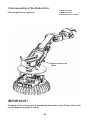
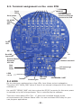
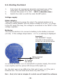
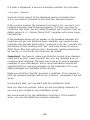
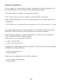
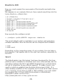
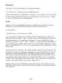
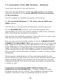
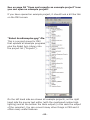
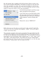
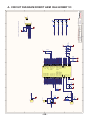
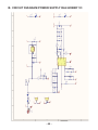
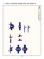
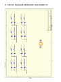
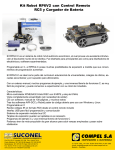
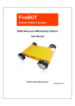
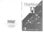
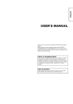
1
EDUCATIONAL ROBOT
ROBOT ARM HOBBY V3
MOUNTING INSTRUCTIONS: Model RA2-HOBBY
© AREXX - THE NETHERLANDS V0513
-1-
Table of Contents
1. Product description ROBOT ARM 5
2.
Required tools7
3.
Part list8
4. Mounting instructions10
5.
Electronics23
6. Software installation27
7.
Programmer and Loader40
7.1
Robot loader41
7.2
Connection of USB interface Windows
42
7.3
Connection of USB interface LINUX
45
7.4
Testing the USB interface
46
7.5
Opening a port Linux47
7.6
Selftest48
7.7
Calibration50
7.8
Keyboard test52
8.
RACS53
9.
Programming the ROBOT ARM59
xx.APPENDIX
A. Circuit diagram Robot Arm68
B. Circuit diagram Power Supply
69
C. Circuit diagram Connectors70
D. Circuit diagram Keyboard71
E. PCB72
AREXX and ROBOT ARM are registered trademarks of AREXX Engineering - HOLLAND.
© English translation (March 2013): AREXX Engineering (NL).
This manual is protected by laws of Copyright. Any full or partial reproduction of the contents are forbidden without prior written authorization by the European importer. :
AREXX Engineering - Zwolle (NL).
Manufacturer and distributor cannot be held responible for any damage resulting from mishandling, mounting
mistakes or disrespect of the instructions contained in the manual.
Subject to changes without prior notice.
Technical mounting support:
Manufacturer:
AREXX Engineering
DAGU HI-TECH
European importer:
AREXX Engineering
ZWOLLE The Netherlands
WWW.AREXX.COM
WWW.ROBOTERNETZ.DE
© AREXX Holland and DAGU China
© English translation: AREXX - The Netherlands
-2-
Impressum
©2007 AREXX Engineering
Nervistraat 16
8013 RS Zwolle
The Netherlands
Tel.: +31 (0) 38 454 2028
Fax.: +31 (0) 38 452 4482
E-Mail: [email protected]
This manual is protected by the laws of Copyright. It is
forbidden to copy all or part of the contents without prior
written authorization!
Product specifications and delivery contents are subject to
changes. The manual is subject to changes without prior
notice.
You can find free updates of this manual on
http://www.arexx.com/
“Robot Arm PRO und -Hobby” are registered trademarks from AREXX Engineering.
All other trademark are the property of their owners. We are not responsible for the
contents of external web pages that are mentioned in this manual!
Information about limited warranty and responsibility
The warranty granted by AREXX Engineering is limited to the replacement or repair of the
Robot Arm and its accessories within the legal warranty period if the default has arisen from
production errors such as mechanical damage or missing or wrong assembly of electronic
components except for all components that are connected via plugs/sockets.
The warranty does not apply directly or indirectly to damages due to the use of the robot.
This excludes claims that fall under the legal prescription of product responsibility.
The warranty does not apply in case of irreversible changes (such as soldering of other
components, drilling of holes, etc.) of the Robot Arm or its accessories or if the Robot Arm
is damaged due to the disrespect of this manual!
The warranty is not applicable in case of disrespect of this manual! In addition, AREXX
Engineering is not responsible for damages of all kinds resulting from the disrespect of this
manual! Please adhere above all to the „Safety recommendations“ in the Robot Arm
manual.
Please note the relevant license agreements on the CD-ROM!
IMPORTANT
Prior to using this robot arm for the first time, please read this manua thoroughly up to the
end! They explain the correct use and inform you about potential dangers! Moreover they
contain important information that might not be obvious for all users.
Important safety recommendation
This module is equipped with highly sensitive components. Electronic components are
very sensitive to static electricity discharge. Only touch the module by the edges and avoid
direct contact with the components on the circuit board. Please do never overload the servo’s
-3-
Symbols
This manual provides the following symbols:
The “Attention!” Symbol is used to mark important details.
Neglecting these precautions may damage or destroy the robot and/or additional components and additionally you may
risk your own health or the health of other persons!
The “Information” Symbol is used to mark useful tips and
tricks or background information. In this case the information is to be considered as “useful, but not necessary”.
Safety recommendations
-
Check the polarity of the batteries or power supply.
Keep all products dry, when the product gets wet remove the batteries or power directly.
Remove the batteries or power when you are not using the product for a longer period.
Before taking the module into operation, always check it and its cables for damage.
If you have reason to believe that the device can no longer be operated safely,
disconnect it immediately and make sure it is not unintentionally operated.
- Consult an expert if you are unsure as to the function, safety or connection of the module.
- Do not operate the module in rooms or under unfavourable conditions.
- Do not overload the servo’s
- This module is equipped with highly sensitive components. Electronic components are
very sensitive to static electricity discharge. Only touch the module by the edges and avoid
direct contact with the components on the circuit board.
Normal use
This product was developed as an experimental platform for all persons which are interested
in robotics. Main goal is to learn how you can program the device in C-langue. This product
is not a toy; it is not suitable for children under 14 years of age!
This robot arm is also not an industrial robot arm, with industrial specifications and
preformance!
It may only be used indoors. The product must not get damp or wet. Also be carful with
condence when you take it from a cold to an warm room give it time to adapt on the new
coditions before you use it.
Any use other than that described above can lead to damage to the product and may
involve additional risks such as short circuits, fire, electrical shock etc.
Please read all the safety instructions of this manual.
-4-
1. PRODUCT DESCRIPTION ROBOT ARM
The ROBOT ARM is an affordable robot for the hobbyist. It is ideally
suited to learn the basics of electronics, mechanics and programming. The ROBOT ARM is controlled by a powerful ATMEGA64
microcontroller that is programmable via Open Source Tools in C.
The user can upload his own programs simply and easily via the
supplied USB interface and the Uploader software. The I/O in- and
outputs together with the flexible I2C bus system allow the
addition of extra modules thus enabling the robot to react to its
environment.
Contents of the package:
-
Complete Robot Arm construction set
(mechanics and electronics)
USB interface with lead
CD-ROM containing all required software and manuals
-
-
1.2. Specifications:
-
-
-
-
-
-
-
-
-
-
ATMEGA64 processor
Various available I/O in/outputs
I2C bus
4 mini-servos DGServo 12g
2 maxi-servos DGServo S07NF STD
Plastic arm and metal chassis
Arm length: 260 mm
Height: 320 mm
Base diameter: 150 mm
Power supply: 9-14V
Warnings
*
*
*
*
The right of return does not apply after opening the plastic bags containing parts and components.
Read the manual thoroughly prior to assembling the unit.
Be careful when handling tools.
Do not assemble the robot in presence of small children. They can get hurt with the tools
or swallow small components and parts.
* Check the correct polarity of the batteries.
* Make sure that batteries and holder remain always dry. If the ROBOT ARM gets wet, remove the
batteries and dry all parts as thoroughly as possible.
* Remove the batteries if the ROBOT ARM will not be used for more than one week.
-5-
1.3. What can we do with the Robot Arm?
-
Transfer example and new programs into the Robot Arm.
-
Control the Robot Arm via a keyboard
-
Control and program the Robot Arm via the RACS software.
-
Extend the Robot Arm with ready-to-use extension modules
so that it can hear, feel and see in order to react to its
environment
-
Just as genuine robots can build e.g. cars, this robot can also
do some tasks for you.
-
The Robot Arm can communicate with its environment and
many other units via its I2C interface.
-
Artificial intelligence: The Robot Arm improves its software
automatically via its selflearning software.
-6-
2. Required tools
Needle-nose
pliers
Sidecutter
Screwdriver set
Screwdriver
Double open-end
wrench
Included
Included
Selftapping screws (Parker)
Selftapping screws behave like wood screws i.e.
they cut a thread into the material in a rotating
motion that functions like a nut. To this end, this type
of screw has a larger thread and a sharper tip as a
normal screw.
Selftapping screws have a cutout at the top
that makes it easier to drill into the material.
The best way to fasten such a screw is:
2
3
1
1 Drive the screw into the material
2 Slightly loosen the screw
3 Tighten the screw again
If the screws are loosened and tightened too often, the hole enlargens gradually
and the screw doesn’t fit anymore properly.
Locknut
Fastening a locknut
Do not force the screws otherwise
the plastic may crack.
Locknut
Double open-end wrench:
The set includes a double open-end wrench. Use this
wrench for the M2 and M3 nuts.
You can use this wrench instead of pliers.
-7-
3. PART LIST
Servomotor
Servolever
CD
USB lead
Keyboard
O 2x
O 1x
O 1x
O 1x
O 4 x Mini
DGServo 12g
O 2 x Maxi
DGServo S07NF STD
Disk with
axis
O 4x
Servo disc
O 4x
Spacer for Servo
O 2x
Spacer
M3x6
Holder for
maxi-servo
O 1x
Cover for maxiservo holder
O 1x
Cover for
servo holder
Spiral
O 4x
-8-
O 1x
O 1x
Spacer
M3x30
O 4x
Servo holder
-dual
O 1x
Servo holder
for finger servo
Servo holder
Wrist
O 1x
O 1x
Servo bottom plate
O 1x
Coupling rod
Selftapping screw
M2.3x8
O 8x
O 4x
Round-head
screw M3x6
O 4x
O 1x
Keyboard lead Servo exten1,5m
sion lead
O 1x
Servo screw
small M2x6
Programming
lead
O 1x
PCB
O 1x
O 3x
O 1x
Program
adaptor
O 1x
Robot Arm base
O-Ring M3
Fingertip
Servo screw
large M2.3x6
O 10x
Round-head
screw M3x8
O 1x
Selftapping screw
M2.6x6
O 2x
O 8x
-9-
Selftapping screw
M3.5x8
O 4x
O 8x
Round-head screw
M3x10
O 1x
Nut
M3
O 4x
Locknut M3
O 4x
4. Mounting instructions mechanical
Mounting the bottom servo:
Following parts are required:
1x Bottom plate
1x Maxi-servo
4x Round-head screw M3x8
4x Nut M3
Screw M3x8
Maxi-servo
Fasten the servo exactly as described in the
drawings.
Servo
Bottom plate
M3 Nut
Mounting the servo arm:
Following parts are required:
Servo arm screw
Servo arm
Fasten the servo arm on the servo,
see detailed drawing!
- 10 -
1x Bottom plate with servo
1x Servo arm
1x Servo screw large M2.3x6
Mounting the bottom servo:
Following parts are required:
1x Bottom part
1x Maxi-servo holder
4x Servo screw small M2x6
Selftapping screw
M2x6
Maxi-servo holder
Mount the servo holder on the
servo arm, please look at the
detailed drawing!
Bottom plate
Mounting the servo holder:
1x Bottom plate with servo
holder
1x Disc with axis
1x Round-head screw M3x8
1x Locknut M3
Following parts are required:
Round-head screw M3x8
Disc with
axis
Servo holder
Locknut
Bottom plate
Mount the servo axis on the servo. Please refer to the detailed drawing!
- 11 -
Mounting the servo:
1x Assembled bottom plate
1x Servo large
1x Servo spacer
4x Round-head screw M3.5x8
Following parts are required:
Spacer for the
servo
Screw M3.5x8
Servo
IMPORTANT!
Don’t forget the spacer for the
servo!
Bottom plate
Mounting the cover for the servo holder:
Following parts are required:
1x Assembled bottom plate
1x Servo holder cover
1x Selftapping screw
M3x10
Selftapping screw
M3x10
Cover
Mount the cover exactly as decribed in
the drawing.
Bottom plate
- 12 -
Mounting the servo arm:
1x Assembled bottom plate
1x Servo arm
1x Servo screw large M2.3x6
Following parts are required:
Mount the servo arm exactly as described
in the drawing!
Servo arm
Servo screw
M2.3x6
Bottom plate
Mounting the servo arm:
1x Assembled bottom plate
1x Servo coupling rod
1x Servo screw small M2x6
2x Servo screw large M2.3x6
Following parts are required:
Coupling rod
TEST!
Can the rod rotate freely at
180 degrees?
Servo screw
M2.3x6
Servo screw
M2x6
Bottom plate
Mount the servo arm exactly as described in the drawing!
- 13 -
Mounting the dual servo:
For the final assembly of the dual servo, following parts are required:
Round-head screw
M3 x 8
Disc with
axis
O-Ring M3
1x Dual servo holder
2x Disc with axis
2x Round-head screw M3 x 8
2x O-Ring M3
2x Locknut M3
4x Selftapping screw 2.6x6
1x Cover
3x Selftapping screw 2.3x8
2x Servo disc
2x Servo screw small M2x6
2x Servo DGServo 12g
Locknut M3
Dual servo holder
Mount the dual servo exactly and in
the same order as described in the
drawing!
Selftapping screw
2.6x6
Selftapping screw
2.3x8
Miniservo DGServo 12g
Cover for dual servo
holder
Dual servo holder
Servo disc
with servos
Dual servo holder
with servos
Servo screw
M2x6
- 14 -
Mounting the dual servo holder:
Following parts are required:
1x Assembled bottom plate
1x Dual servo holder
2x Servo screw small M2x6
2x Servo screw large M2.3x6
Servo screw
M2x6
TEST!
Can the dual servo rotate
freely at 180 degrees?
Servo screw
M2.3x6
Bottom plate
Mount the dual servo exactly as described
in the drawing.
Mounting the wrist servo:
Following parts are required:
1x Miniservo DGServo 12g
1x Servo holder wrist
2x Selftapping screw M2.6x6
Selftapping screw
2.6x6
Miniservo DGServo 12g
Servo holder
wrist
Mount the wrist servo exactly as described in the drawing.
- 15 -
Final assembly of the wrist servo:
Following parts are required:
1x Assembled wrist
1x Servo disc
1x Servo screw small M2x6
Servo disc
Servo screw M2x6
Assembled wrist
Mount the servo disc exactly as described in the drawing.
- 16 -
Mounting the finger servo holder:
Following parts are required:
1x Assembled wrist
1x Finger servo holder
2x Servo screw small M2x6
Finger servo holder
Assembled wrist
Servo screw M2x6
Mount the finger servo holder exactly as described in the drawing.
Mounting the finger servo holder:
Following parts are required:
1x Assembled wrist
1x Finger servo holder
1x Servo disc
1x Screw M3x8
1x O-Ring M3
1x Locknut M3
Wrist assembly
Finger servo holder
TEST!
Can the wrist rotate freely at
180 degrees?
Mount the servo disc exactly as described in
the drawing.
Round-head screw
M3x8
O-Ring M3
Locknut M3
Servo disc
- 17 -
Mounting the finger servo:
1x Assembled wrist
1x Mini servo DGServo 12g
2x Selftapping screw M2.6x6
Following parts are required:
Fasten the servo at the servo holder exactly as
described in the drawing
Selftapping screw M2.6x6
Mini servo DGServo 12g
Mounting the finger servo holder:
1x Assembled Wrist
1x Servo disc
1x Servo screw small M2x6
Following parts are required:
Assembled
wrist
Fasten the disc on the servo
exactly as described in the
drawing
Servo screw
M2x6
- 18 -
Mounting the finger:
Following parts are required:
Mount the finger exactly as described in the
drawing.
Assembled
wrist
1x Assembled wrist
1x Finger
2x Servo screw small M2x6
2x Servo screw large M2.3x6
Servo screw
M2.3x6
Finger
TEST!
Can the finger rotate FREELY?
Servo screw
M2x6
Final arm assembly:
1x Assembled wrist
1x Assembled bottom plate
2x Servo screw small M2x6
2x Servo screw large 2.3x6
Following parts are required:
Servo screw
M2x6
Assembled
wrist
Servo screw
M2.3x6
Assembled
Bottom plate
Fasten the wrist on the arm exactly as described in
the drawing.
- 19 -
Mounting the base and the PCB:
Following parts are required:
1x Metal base
4x Spacer M3x6
1x PCB
4x Spacer M3x30
Spacer M3x6
Metal base
Spacer M3x30
PCB
IMPORTANT!
Avoid direct contact with the
components on the circuit board.
Base
- 20 -
Final assembly of the Robot Arm :
1x Base assembly
1x ARM assembly
4x Round-head screw M3x6
Following parts are required:
Round-head screw
M3x6
IMPORTANT!
Complete all the wiring prior to proceeding with these steps. Please refer to the
circuit diagram on page 25 and 51.
- 21 -
READY !
- 22 -
5. ELECTRONICS
5.1. Features and technical data
This section provides an overview of the robot arm features and an introduction of some basic keywords, to make you familiar with the terminology used
in this manual. Most of these keywords will be explained in later chapters.
Features, components and technical data of the robot arm:
● Powerful Atmel ATMEGA64 8-Bit Microcontroller
◊ Speed 16 MIPS (=16 Million Instructions per Second) at 16MHz clock frequency
◊ Memory: 64KB Flash ROM, 4KB SRAM, 2KB EEPROM
◊ Freely programmable in C (using WinAVR / avr-gcc)!
● Flexible expansion system, based on the I²C-Bus
◊ Only two signals required (TWI -> “Two Wire Interface”)
◊ Transfer speed up to 400kBit/s
◊ Master->Slave architecture
◊ Up to 127 Slaves may be connected to the bus simultaneously
◊ Very popular bus-system. The market provides a lot of standard ICs,
sensors and other components, which may often be connected directly.
● Mounting possibilities for wireless modules
◊ RP6 WIFI
◊ Bluetooth
◊ APC-220
● USB PC Interface for program uploads from PC to microcontroller
◊ Wired connection for maximum transfer speed. Program upload will
usually run at 500kBaud, filling the total free memory space
(30KB, 2KB are reserved for the Bootloader) within seconds.
◊ The interface may be used for programming all available expansion
modules for the robot arm with AVR Microcontrollers
(RP6-256-WIFI module).
◊ It may be used for communication between the robot and expansion
modules. For example you can use this for debugging purposes by
transferring measurement data, text messages and other data to the PC.
◊ The interface driver provides a virtual comport (VCP) for all popular
operating systems including Windows 2K/XP/Vista and Linux. The VCP can
be used in standard terminal programs and customized software.
- 23 -
5.2. Modifications V3 PCB type RA1 PRO and RA2-HOBBY
-
New TI TPS54332 DC/DC converter, 3500mA
New LDO voltageregulator for the 5V microprocessor power
Extra power supply connectors for VCC and Servo power
6 pre amplifiers for current measurement of all servos over a shunt resistor
The Reset switch is now a start/stop switch to start and stop operation
of the program.
- Autostart (= the program starts automatically shortly after switching on) can
be configured through the robotloader if you like.
- Extra extension connectors with all free I/O Pins from the ATMEGA64.
- I2C Bus connexion, compatible with RP6 XBUS extension modules, for
example the RP6-M256 WLAN Module.
- Socket for APC220 or Bluetooh wireless module.
- 4 blue status LEDs instead of a green/red LED-pair.
- 4A fuse.
- 16.000 MHz Crystal instead of 16.384MHz.
- Pull-up resistors for the I2C Bus are located on the PCB now.
- On/off switch separates the Logic. The servo power from the DC/DC
converter is controlled by the microprocessor.
- Input power is 7 - 14 Volt (absolute maximum is 18 Volt)
ROBOT ARM EXTENSIONS
- RP6v2-M256-WIFI Module to control the robot wireless arm over a network
- ARX-APC220 for RACS 433 MHz wireless control
- ARX-BT03 for ANDROID wireless bluetooth control
See also the AREXX APC-220, Android and WIFI module manuals
- 24 -
5.3. Terminal assignment on the main PCB
SW1/SW2
Switch I/O
Servo
LED
See also page 51
how to connect the
Servos to the PCB
Servo power
I2C & RP6
X-BUS
WIFI
Power
LED
SPI
I/O
Boot/ISP
Important!
ISP
Drahtlos Module
Bluetooth
APC-220
Batterie anschluß
Start
Stop
Reset
DC Spannungs
Buchse
LEDS
1,2,3,4
5.4 LEDS
Tastatur
Sicherung 4A
EIN / AUS
Schalter
PROGRAMM / UART
On the robot arm mainboard are a few LEDs, here folows a short explanation;
The yellow LED “MAIN_PWR” shows if there is an external voltage and if the robot is
switched on.
the red LED “SERVO_PWR” only burns when the DC/DC convertor for the servo power
is switched on by the mikroprocessor. This is controlled by the software.
There are 4 blue status LEDs “SL1 - 4” which are controlled directly by the
microprocessorn die 4 blauen Status LEDs. You can use these LEDs freely for your
own program applications.
- 25 -
5.5. Starting the Robot
1.
2.
3.
First check all mechanical assembly and electronic of the
robot arm, connect the servos (see page 25 and 51).
Connect the power 9- to 14V (18 V = absolute max.).
Switch the robot on with the main On/Off switch.
Voltage supply
Mains adaptor
There are 2 options to power the robot. The easiest solution is to
connect a mains adaptor with an output voltage of 9-14V / 3-4 Amps
to the DC input.This way, the voltage is connected to the INPUT of the
voltage regulator.
Batteries
The second solution is to connect a battery to the battery terminal
(9-14V). If the voltage drops below < 6.7 V, a warning is displayed.
Important!
The “ISP/BOOT” Jumper
should be in left position for
normal use, see picture below.
Battery terminal
9 to 14 Volt
DC Terminal
9 to 14 Volt
As soon as the Robot Arm is connected to a power supply, the servos
move slightly and the yellow LED (Power LED) lights up.
So, the start was not as difficult as that and it looks, as if the job is
finished now. The real hard work does only start now.....!
But.... first, let’s look at chapter 6 in which we will install the software
- 26 -
6. Software Installation
Let’s do now the software installation. A properly installed software
is of paramount importance for all following chapters.
As you need administrator rights, you have to log into your system
as an administrator!
We recommend to read the whole chapter thoroughly first and then
start with the installation step by step.
The user must have basic knowledge of Windows or Linux based
computers and be familiar with current programs such as file managers, web browsers, text editors, file compression software (WinZip,
WinRAR, unzip and others.) and eventually Linux shell etc.! If your
computer knowledge is very limited, you should learn more about
systems before you start using the Robot Arm. This manual is not
intended as an introduction to computers which would go much too
far! It is only aimed at the Robot Arm, its programming and the specific software required.
The Robot Arm CD-ROM
You have probably already inserted the CD-ROM into your computer
drive - if not, please do it now! In Windows, the CD menu should
appear shortly afterwards per autostart. If not, you can open the file
“start.htm” with a web browser as e.g. Firefox in the main directory
of the CD via a file manager. By the way, the installation files for
Firefox are also on the CD in the folder
<CD-ROM drive>:\Software\Firefox
if ever you haven’t installed an updated web browser (it should be
at least Firefox 1.x or Internet Explorer 6 ...)
After the language selection, you will find in the CD menu, in addition to this manual (that you can also download from our home
page), information, data sheets and pictures also the menu item
“Software”. It contains all software tools, USB drivers and example
programs with source code for the Robot Arm.
Depending on the safety settings of your web browser, you can start
the installation programs directly from the CD!
- 27 -
If the safety settings of your web browser don’t allow a direct installation from the CD-ROM, you have to copy the files first into a
directory on your hard disc and start the installation from there.
For more details please refer to the software page in the CD menu.
Alternatively, you can also switch to the CD drive via a file manager
and install the software from the CD. The names of the directories
are self-explanatory so that you can allocate them easily to the corresponding software packages and operating systems.
WinAVR - for Windows
We will start with the installation of WinAVR. WinAVR is - as the
name says - only available for Windows!
Linux users can skip to the next section.
WinAVR (pronounce like the word “whenever”) is a collection of
many useful and necessary programs for the software development
for AVR micro controllers in C language. In addition to the GCC for
AVR (designated by the term “AVR-GCC”, more details later) WinAVR
includes the convenient source text editor “Programmers Notepad 2”
that we will also use for the program development of the Robot Arm.
WinAVR is a private project that is not supported by a company. It is
available for free in the internet. You will find updated versions and
more information at:
http://winavr.sourceforge.net/
In the meantime the project gets the official support from ATMEL
and the AVRGCC is available for AVRStudio, the development environment for AVR’s from ATMEL. However we will not describe it in
this manual as Programmers Notepad is much better suited for our
purpose.
The WinAVR installation file is on the CD in the folder:
<CD-ROM drive>:\Software\AVR-GCC\Windows\WinAVR\
The installation of WinAVR is simple and self-explanatory. Normally
you don’t need to change any settings. So, just click on “Continue”!
- 28 -
If you use Windows Vista or Windows 7, you must install the latest
version of WinAVR! It should also work perfectly with Windows 2K
and XP. If not, you can try one of the older versions that are also on
the CD (before you make a new installation of WinAVR, you have to
uninstall the existing version first!). Officially Win x64 is not yet supported but the CD contains a patch for Win x64 systems if a problem
arises. You will find more information on the software page of the
CD menu.
AVR-GCC, avr-libc uad avr-binutils - for Linux
(Windows users can skip this section!)
Linux might require more effort. Some distributions already contain
the required packages but they are mostly obsolete versions. Therefore you need to compile and install newer versions. It is impossible to describe in detail the numerous Linux distributions as SuSE,
Ubuntu, RedHat/Fedora, Debian, Gentoo, Slackware, Mandriva etc.
that exist in many versions with their own particularities and we will
keep here only to the general lines.
The same applies to all other Linux sections in this chapter!
The procedure described here must not necessarily work for you.
It is often helpful to search in the internet e.g. for “<LinuxDistribution> avr gcc” or similar. (Try different spellings). The same applies
to all other Linux sections - of course with the suitable keywords! If
you encounter problems with the installation of the AVR-GCC, you
can also take a look in our robot network forum or in one of the
numerous Linux forums. First of all, you have to uninstall already
installed versions of the avr-gcc, the avr-binutils and the avr-libc
because, as said, these are mostly obsolete. You can do that via the
package manager of your distribution by searching for “avr” start up
and uninstall the three above mentioned packages - as far as they
exist in your computer. You can find out easily if the avr-gcc has
already been installed or not via a console as e.g.
> which avr-gcc
- 29 -
If a path is displayed, a version is already installed. So just enter:
> avr-gcc --version
and look at the output. If the displayed version is smaller than
3.4.6, you have to uninstall in any case this obsolete version.
If the version number lies between 3.4.6 and 4.1.0, you can try to
compile programs (see following chapter). If it fails, you have to
install the new tools. We will install hereafter the currently most updated version 4.1.1 (status March 2007) together with some important patches.
If the packages above do not appear in the package manager although an avr-gcc has definitely been installed, you need to erase
manually the relevant binary files- i.e.search in all /bin, /usr/bin etc.
directories for files starting with “avr” and erase these (of course
ONLY these files and nothing else!). Eventually existing directories
as /usr/avr or /usr/local/ avr must also be erased.
Important: You have to make sure that the normal Linux development tools as GCC, make, binutils, libc, etc. are installed prior to
compiling and installing! The best way to do so is via the package
manager of your distribution. Every Linux distribution should be
supplied with the required packages on the installation CD or updated packages are available in the internet.
Make sure that the “texinfo” program is installed. If not, please install the relevant package before you continue - otherwise it will not
work!
Having done that, you can start with the installation itself.
Now you have two options: either you do everything manually or
you use a very simple to use installation script.
We recommend to try the installation script first. If this doesn’t
work, you can still install the compiler manually.
- 30 -
Attention:
You should have enough free disk space on your hard disk!
Temporarily more than 400Mb are required. Over 300Mb can be
erased after the installation but during the installation, you need all the
space.
Many of the following installation steps require ROOT RIGHTS, so
please log in with “su” as root or execute the critical commands with
“sudo” or something similiar as you have to do it in Ubuntu e.g. (the
installation script, mkdir in /usr/local directories and make install require
root rights).
Please note in the following the EXACT spelling of all commands!
Every sign is important and even if some commands look a bit strange,
it is all correct and not a typing mistake! (<CD-ROM-drive> has of
course to be replaced by the path of the CD-ROM drive!)
The folder on the CD:
<CD-ROM drive>:\Software\avr-gcc\Linux
contains all relevant installation files for the avr-gcc, avr-libc and
binutils.
First of all, you have to copy all installation files in a directory on your
hard disk - this applies for both installation methods! We will use
the Home directory (usual abbreviation for the current home directory is
the tilde: „~“):
> mkdir ~/Robot Arm
> cd <CD-ROM drive>/Software/avr-gcc/Linux
> cp * ~/Robot Arm
After the successful installation you can erase the files to save space!
- 31 -
Automatic Installation Script
Once you have made the script executable via chmod, you can start
immediately:
> cd ~/Robot Arm
> chmod -x avrgcc_build_and_install.sh
> ./avrgcc_build_and_install.sh
Answer “y” to the question if you want to install with this configuration or not.
PLEASE NOTE: The compilation and installation will take some time
depending on the computing power of your system (e.g about 15
min. on a 2GHz Core Duo Notebook. Slower systems will need longer).
The script will include also some patches. These are all the .diff files
in the directory.
If the installation was successful, following message will be displayed:
(./avrgcc_build_and_install.sh)
(./avrgcc_build_and_install.sh)
(./avrgcc_build_and_install.sh)
GNU tools
(./avrgcc_build_and_install.sh)
space:
(./avrgcc_build_and_install.sh)
(./avrgcc_build_and_install.sh)
installation of avr GNU tools complete
add /usr/local/avr/bin to your path to use the avr
you might want to run the following to save disk
rm -rf /usr/local/avr/source /usr/local/avr/build
As suggested, you can execute
rm -rf /usr/local/avr/source /usr/local/avr/build
This erases all temporary files that you will not need anymore.
You can skip the next paragraph and set the path to the avr tools.
If the execution of the script failed, you have to look attentively
to the error message (scroll the console up if necessary). In most
cases it is just a matter of missing programs that should have been
installed earlier (as e.g. the before mentioned texinfo file). Before
you continue after an error, it is recommended to erase the already
generated files in the standard installation directory “/usr/local/avr“
– preferably the whole directory.
- 32 -
If you don’t know exactly what has gone wrong, please save all
command line outputs in a file and contact the technical support.
Please join always as much information as possible. This makes it
easier to help you.
GCC for AVR
The GCC is patched, compiled and installed a bit like the binutils:
> cd ~/Robot Arm> bunzip2 -c gcc-4.1.1.tar.bz2 | tar xf > cd gcc-4.1.1
> patch -p0 < ../gcc-patch-0b-constants.diff
> patch -p0 < ../gcc-patch-attribute_alias.diff
> patch -p0 < ../gcc-patch-bug25672.diff
> patch -p0 < ../gcc-patch-dwarf.diff
> patch -p0 < ../gcc-patch-libiberty-Makefile.in.diff
> patch -p0 < ../gcc-patch-newdevices.diff
> patch -p0 < ../gcc-patch-zz-atmega256x.diff
> mkdir obj-avr
> cd obj-avr
> ../configure --prefix=$PREFIX --target=avr --enablelanguages=c,c++ \
--disable-nls --disable-libssp –with-dwarf2
> make
> make install
After the \ just press Enter and continue to write. This way the command can be spread over several lines, but you can also just drop it.
AVR Libc
And last but not least the AVR libc:
>
>
>
>
>
>
cd ~/Robot Arm
bunzip2 -c avr-libc-1.4.5.tar.bz2 | tar xf cd avr-libc-1.4.5
./configure --prefix=$PREFIX --build=`./config.guess` --host=avr
make
make install
- 33 -
Important: at –build=`./config.guess` make sure to put a backtick
` (à <-- the grave accent on the a! ) and not a normal apostrophy
or quotation marks as this wouldn’t work.
Set the Path
You must make sure now that the directory /usr/local/avr/bin is
registered in the path variable otherwise it will be impossible to
retrieve the avr-gcc from the console or from the makefiles. To
that end, you have to enter the path in the file /etc/profile or /etc/
environment or similiar (varies from one distribution to another) –
separated by a colon “:” from the other already existing entries. It
could look in the file like:
PATH=”/usr/local/bin:/usr/bin:/bin:/usr/X11R6/bin:/usr/local/avr/bin“
Now enter in a console “avr-gcc -–version“ as described above. If it
works, the installation was successfull!
- 34 -
Manual Installation
If you prefer to install the compiler manually or the installation via
th script failed, you can follow the instructions below.
The description is based on following article:
http://www.nongnu.org/avr-libc/user-manual/install_tools.html
that is also included on the CD in PDF format in the AVR Libc documentation:
<CD-ROM drive>:\Software\Documentation\avr-libc-user-manual-1.4.5.pdf
Our description here is much shorter but includes a few important
patches. Without these, some tings will not work properly.
First of all we have to create a directory in which we wil install all
tools. That should be /usr/local/avr.
Also enter in a console AS A ROOT:
> mkdir /usr/local/avr
> mkdir /usr/local/avr/bin
It must not necessarily be this directory. We just create the variable
$PREFIX for this directory:
> PREFIX=/usr/local/avr
> export PREFIX
This must be added into the PATH variable:
> PATH=$PATH:$PREFIX/bin
> export PATH
- 35 -
Binutils for AVR
Now you must unpack the sourcecode of the binutils and add a few
patches.
We suppose in our example that you have copied everything into the
home directory ~/Robot Arm:
>
>
>
>
>
>
>
>
>
>
cd ~/Robot Arm
bunzip2 -c binutils-2.17.tar.bz2 | tar xf cd binutils-2.17
patch -p0 < ../binutils-patch-aa.diff
patch -p0 < ../binutils-patch-atmega256x.diff
patch -p0 < ../binutils-patch-coff-avr.diff
patch -p0 < ../binutils-patch-newdevices.diff
patch -p0 < ../binutils-patch-avr-size.diff
mkdir obj-avr
cd obj-avr
Now execute the configure script:
> ../configure --prefix=$PREFIX --target=avr --disable-nls
This script detects what is available in your system and generates
suitable makefiles. Now the binutils can be compiled and installed:
> make
> make install
Depending on the computing power of your system, this can take a
few minutes. That applies also to the next two sections, especially to
the GCC!
Java 6
The RobotLoader (see Info below) has been developed for the Java
platform and is suitable for Windows and Linux (theoretically also for
operating systems like OS X but AREXX Engineering is unfortunately
not yet in a position to give official support). To make it work, you
need to install an updated Java Runtime Environment (JRA). It is
often already installed on the computer but it must be at least version
1.6 (= Java 6)! If you have no JRE or JDK installed, you must install
the supplied JRE 1.6 from SUN Microsystems or alternatively
download a newer version from;
http://www.java.com or http://java.sun.com.
- 36 -
Windows
The JRE 1.6 for Windows is in following folder:
<CD-ROM drive>:\Software\Java\JRE6\Windows\
Under Windows the installation of Java is very simple. You just have
to start the setup and follow the instructions on the screen - that’s
it. You can skip the next paragraph.
Linux
Under Linux the installation doesn’t present any major problems
although some distributions require some manual work.
In the folder:
<CD-ROM drive>:\Software\Java\JRE6\
you will find the JRE1.6 as an RPM (SuSE, RedHat etc.) and as a
self-extracting archive “.bin“. Under Linux it is advisable to look for
Java packages in the package manager of your distribution (keywords e.g. „java“, „sun“, „jre“, „java6“ ...) and use the packages of
your distribution rather than those on the CD-ROM! However make
sure to install Java 6 (=1.6) or a newer version but definitely not an
older one!
Under Ubuntu or Debian, the RPM archive doesn’t work directly. You
will have to use the package manager of your distribution to find a
suitable installation package. The RPM should however work well
with many other distributions like RedHat/Fedora and SuSE. If not,
you always have the solution to unpack the JRE (e.g. to /usr/lib/
Java6) from the self-extracting archive (.bin) and set manually the
paths to the JRE (PATH and JAVA_HOME etc.).
Please refer to the installation instructions from Sun that you will
find also in the above mentioned directory and on the Java website
(see above).
- 37 -
You can check if Java has been correctly installed by entering
the command “java-version” in a console. The output should be
approximately as follows:
java version “1.6.0”
Java(TM) SE Runtime Environment (build 1.6.0-b105)
Java HotSpot(TM) Client VM (build 1.6.0-b105, mixed mode, sharing)
If the output is totally different, you have either installed the wrong
version or there is another Java VM installed in your system.
Robot Loader
The Robot Loader has been developed to load easily new programs
and all extension modules into the Robot Arm (as long as the modules are fitted with a compatible bootloader). Moreover it contains a
few useful extra functions as e.g. a simple terminal program.
It is not necessary to install the RobotLoader. Just copy the program
somewhere in a new folder on the hard disk.
<CD-ROM drive>:\Software\RobotLoader\RobotLoader.zip
Unpack the program somewhere on your hard disk e.g. in a new
folder C:\Programme\RobotLoader (or similiar). This folder contains
the
RobotLoader.exe file that you can start with a double-click.
The Robot Loader program itself is in the Java archive (JAR) RobotLoader_lib.jar. Alternatively you can start this via the command line:
Under Windows:
java -Djava.library.path=”.\lib” -jar RobotLoader_lib.jar
Linux:
java -Djava.library.path=”./lib” -jar RobotLoader_lib.jar
- 38 -
The long -D option is necessary to enable the JVM to find all used
libraries. Windows doesn’t require this and you can just start with the
.exe file. Linux requires the shell script ”RobotLoader. sh“. It might
be necessary to make the script executable (chmod -x ./RobotLoader.
sh). After that you can start it in a console with “./RobotLoader.sh“.
It is advisable to create a shortcut on the desktop or in the start
menu to make the start of the Robot Loader more convenient. Under
Windows make a right click on the RobotLoader file.exe and then click
on “Desktop (create shortcut)” in the “Send to” menu.
Robot Arm Library, Robot Arm CONTROL Library and Example
Programs
The Robot Arm Library and the related example programs are in a zip
archive on the CD:
<CD-ROM drive>:\Software\Robot Arm Examples\Robot ArmExamples
[MINI].zip
Just unpack them directly into a directory at your convenience on the
hard disk. It is recommended to unpack the example programs into
a folder on a data partition. Or in the “My files” folder in a sub-folder
“Robot Arm\Examples\“ or else under Linux into the Home directory.
It’s entirely up to you.
The individual example programs will be discussed later in the
software chapter!
- 39 -
7. Programmer and Loader
To load a HEX Robot Arm program from the PC into the Robot Arm,
we will use the USB programming adaptor and our RobotLoader
software.
The loose USB port adaptor transmitter/receiver (transceiver) included in the package must be connected on one side to a USB port
of the computer and on the other side to the Prog/UART port of the
Robot Arm PCB.
The program upload into the Robot Arm erases automatically the
previously existing program.
USB Programming adaptor
RobotLoader software
- 40 -
7.1. Robot Loader
As said, the RobotLoader has been developed to upload easily new
programs into the Robot Arm and into all our robots (provided that
they contain a compatible bootloader).
RobotLoader
If the voltage
drops below
< 6.7 V,
a warning is
displayed.
Other useful extra functions are built-in such as a simple terminal
program.
Terminal window
The RobotLoader itself doesn’t need to be installed. Just copy the
program somewhere in a new folder on the hard disk.
- 41 -
7.2. Connection of the USB interface – Windows
Linux users can skip to the next section!
There are several options to install the USB interface, the easiest
being the installation of the driver BEFORE the first connection
of the hardware.
The CD contains an installation program for the driver.
For 32 and 64 Bit Windows 7, XP, Vista, Server 2003 and
2000 systems:
<CD-ROM drive>:\Software\USB_DRIVER\Win2k_XP\CDM_Setup.exe
For old Win98SE/Me systems, such a handy program does
unfortunately not exist. You need to install an older driver manually
after connecting the equipment (see below).
Just execute the installation program. There will just be a short note
that the driver has ben installed and that’s all.
Now you can connect the USB interfac to the PC. PLEASE DO NOT
CONNECT TO THE ROBOT YET! Just connect to the PC via the USB
lead. Please touch the PCB of the USB interface only at the edges or
at the USB plug or at the plastic shell of the programming plug (see
safety instructions on static discharges)! Please avoid touching any
of the components on the PCB, soldering points or contacts of the
IDE connector unless absolutely necessary in order to prevent static
discharges!
The previously installed driver will be used automatically for the
device without any help from your side. Under Windows XP/2k small
speech bubbles appear at the bottom above the task bar. The last
message should be “The device has been successfully installed and
is ready for use!”.
If you have connected the USB interface before the
installation (or use Win98/Me) – it doesn’t matter so much.
Windows will ask you for a driver. This installation method is also
possible. The driver is also in unpacked format on the CD.
- 42 -
If you are in this situation, a dialogue appears (under Windows) to
install the new driver. You have to indicate the path to the system
where it can find the driver. Under Windows 2k/XP you need to
select first the manual installation and not to look for a web service.
On our CD the driver is in the above mentioned directories.
So, just indicate the directory for your Windows version and eventually a few other files that the system doesn’t find automatically
(they are all in the directories mentioned below!) ...
Under Windows XP and later versions there is often a message that
the FTDI drivers are not signed/verified by Microsoft (normally not
here as the FTDI drivers are signed). This is irrelevant and can be
confirmed without any problem.
Operation
For 32 and 64 Bit Windows 7/8, XP, Vista, Server 2003 and
2000 systems:
<CD-ROM drive>:\Software\USB_DRIVER\Win2k_XP\FTDI_CDM2\
For older Windows 98SE/Me systems:
<CD-ROM drive>:\Software\USB_DRIVER\Win98SE_ME\FTDI_D2XX\
After the installation of the driver a re-start of the computer may be necessary with older versions like Win98SE! PLEASE NOTE: Under Win98/Me only
one of both drivers is working: Either Virtual Comport or the D2XX driver
from FTDI! Unfortunately there is no driver that offers both functions. Normally there is no virtual comport available as the RP6Loader under Windows
uses as a standard the D2XX drivers (you can change this - please contact
our support team!).
Check the Connection of the Device
To check if the device has been correctly installed you can use the
device manager as an alternative to the RobotLoader under Windows XP, 2003 and 2000: Right click on My Computer --> Properties
--> Hardware --> Device manager
- 43 -
OR alternatively: Start --> Settings --> Control panel --> Performance and Maintenance --> System --> Hardware --> Device
manager and check there in the tree view under “Connections (COM
and LPT)” if you find a “USB-Serial Port (COMX)” - the X replacing
the port number, or look under “USB serial bus controller“ for a
“USB Serial Converter“ !
If you wish to uninstall the driver some day
If ever you wish to uninstall the driver (no, not now - this is just
a hint if you need this some day): If you have used the CD ROM
installation program, you can uninstall it directly via Start --> Settings --> Control panel --> Software. In the displayed list you will
find an item “FTDI USB Serial Converter Drivers“ – select it and click
on “uninstall”.
If you have installed the driver manually, you can execute the program ““FTUNIN.exe” in the directory dedicated to the USB driver for
your system! Warning: USB-->RS232 adaptors with FTDI chip set
often also use this driver!
- 44 -
7.3. Connection of the USB Interface – Linux
Windows users can skip this section!
Linux systems with kernel 2.4.20 or higher already include the
required driver (at least for the compatible previous model FT232BM
of the chip on our USB interface, the FT232R). The hardware is automatically recognized and you have nothing else to do. In case of
a problem, you can get Linux drivers (and support and maybe also
newer drivers) directly from FTDI:
http://www.ftdichip.com/
Once the hardware has been connected, you can check under Linux
via: cat /proc/tty/driver/usbserial
if the USB serial port has been correctly installed. This is normally all
you have to do.
It is worth to mention that the Robot Loader uses under Windows
D2XX drivers and the full USB designations appear in the port list
(e.g. ”USB0 | Robot USB Interface | serialNumber“). Whereas under
Linux the virtual comport designations appear such as /dev/ttyUSB0,
/dev/ttyUSB1 etc.. The normal com ports are equally displayed as
“dev/ttyS0“ etc.. In this case you have to try which port is the correct
one!
Unfortunately Linux doesn’t have such a convenient driver that does
both. Therefore it made more sense to use the Virtual Comport drivers that are included in the kernel anyway. The installation of a D2XX
driver would require quite a lot of manual work....
Finalization of Software Installation
Now the installation of the software and the USB interfaces is completed! You just need to copy the most important files from the CD on
a hard disk (especially the complete “Documentation” folder and, if
it hasn’t been done yet, the example programs). This avoids to look
constantly for the CD if you need these files. The folders on the CD
are all named in such a way that they can be easily allocated to the
relevant software packages or documentation!
If you “loose” the CD one day, you can download the most important files as this manual, the RobotLoader
and the example programs from the AREXX home page. You will find there also the links to the other software
packages that you require.
- 45 -
7.4. Testing the USB Interface and starting the
RobotLoader
The next step is a test of the program upload via the USB interface.
Connect the USB interface to the PC (always connect the PC first!)
and the other end of the 10-pin ribbon cable to the “PROG/UART”
connector on the Robot Arm. (Robot Arm MUST BE SWITCHED OFF!)
The 10-pin ribbon cable is mechanically protected against polarity
inversion. As long as it is not forced, it can’t be connected the wrong
way round.
Then start the RobotLoader. Depending
on which language you have selected, the
menus might have a bit different names. The
screen shots show the English version. Via
the menu item “Options->Preferences“ you
can select under “Language /Sprache“ the
required language (English or German) and
then click on OK.
Once you have selected your language, you have to re-start the Robot Loader to validate the changes!
Open a port - Windows
Select the USB port. As long as no other
USB->Serial Adaptor with FTDI controller
is connected to the PC, you will see only
one single entry that you have to select.
If more ports exist, you can identify the port via the name “Robot
USB Interface“ (or „FT232R USB UART“). Behind the port name the
programmed serial number is displayed.
If no ports are displayed, you can refresh the port list via the menu
item “RobotLoader-->Refresh Portlist“ !
WARNING!
If the voltage drops below < 6,7 V, a warning is displayed.
- 46 -
7.5. Open a port – Linux
Linux handles the USB serial adaptor like a normal comport. The
installation of the D2XX driver from FTDI would not be as simple as
that under Linux and the normal virtual comport (VCP) drivers are
included anyway in the current Linux kernels. It works almost the
same as under Windows. You just need to find out the name of the
Robot Arm USB interface and make sure that the USB port is not
unplugged from the PC as long as the connection is open (otherwise
you might have to re-start the RobotLoader to re-connect). Under
Linux the names of the virtual comports are “/dev/ttyUSBx“, x being
a number e.g. “/dev/ttyUSB0“ or “/dev/ttyUSB1“. The names of the
normal comports under Linux are “/dev/ttyS0“, „/dev/tty- S1“ etc..
They also show up in the port list as far as they exist.
The RobotLoader remembers - if there are several ports - which port
you have used last time and selects this port automatically when
you start the program (in general, most of the settings and
selections are maintained).
Now you can click on the button “Connect“! The RobotLoader will
open the port and test if the communication with the bootloader on
the robot is working. The black field “Status” on the bottom should
show the message “Connected to: Robot Arm ...” or similiar together
with an information about the currently measured voltage. If not,
just try again! If it still doesn’t work, there is a mistake! Switch the
robot off immediately and start searching for the error.
If the voltage is too low, a warning is displayed. You should
immediately charge the accumulators (preferably even earlier when
the voltage drops below 6,7V)!
- 47 -
7.6. SELFTEST
The yellow voltage LED lights up when the Robot Arm is switched
on.
The status LED Blinks off when a HEX file is uploaded.
If this worked, you can execute a small selftest program to test the
functioning of all robot systems. Please click on the button “Add” on
the bottom of the Robot Loader window and select the file RobotArmExamples [MINI], „Example_11_Selftest\RobotArm_Selftest.hex“
in the example directory. This file contains the selftest program in
hexadecimal format - that’s why this kind of program file is called
“hex file”. The file just selected appears afterwards in the list. This
way you can add other hex files from your own programs and from
the examples programs (see screen shot where some hex files have
already been added). The Robot Loader is able to manage several
categories of hex files.
This allows to sort the files in a clear way e.g. if several programmable extension modules are mounted on the robot or different
program versions are used. The list is automatically saved at the
end of the program. Of course only the paths to the hex files are
saved, not the hex files themselves. If you work on a program, you
just need to add and select the hex file once. Then you can load the
new program into the microcontroller after every re-compiling of
the program. (you can also use the key combination [STRG+D] or
[STRG+Y], to start the program directly after the transfer). The path
names are of course totally different under the various operating
systems. Nevertheless the RobotLoader suits both, Windows and
Linux, without any changes, as there is a separate list for Windows
and Linux.
Either you continue now with the other example programs
(Examples) of the Robot Arm or else you start with your own software programming.
WARNING!
If the voltage drops below < 6,7 V, a warning is displayed.
- 48 -
Please select the “RobotArm_Selftest.hex“ file in the list and click on
the “Upload!“ button on the top right just below the progress bar.
The program will now be transferred into the MEGA64 processor on
the Robot Arm. This should not take more than a few seconds (max.
5 seconds for the selftest program).
Switch to the tab (at the bottom of the window!) “Terminal“! Alternatively you can also switch to terminal via the menu item “View”.
Important!
The “ISP/BOOT” Jumper
should be in left position for
normal use, see picture below.
Now you can execute the selftest and the calibration of the Robot
Arm. Press the switch Start/Stop Reset on the Robot Arm to start
the program. Later you can do this alternatively via the RobotLoader
menu --> Start or the key combination [STRG]+[S]. However this
time you can test if the switch works properly!
If an error occurs in the selftest, switch the robot off immediately
and start searching for the mistake.
IT IS RECOMMENDED TO START WITH THE CALIBRATION
OF THE ROBOT ARM! SEE PAGE 50.
USE THE CORRECT V3 PRO OR MINI SOFTWARE!
- 49 -
7.7. Calibration
Start the calibration program to calibrate the robot.
To this end, please click on the button “Add” at the bottom of the
RobotLoader window and select the file RobotArmExamples [MINI],
„Example_11_Selftest\RobotArm_Selftest.hex“ in the example directory.
This file contains the selftest program in hexadecimal format. The just
selected file will appear subsequently in the list
(see screenshot).
Select C
(C - Calibrate) in the
calibration program to
start calibration.
Bring all servomotors into central
position so that the Robot Arm
looks
like on page 51.
The servomotors 2-6 are
approximately in a central position
and the finger (servo 1) is almost
closed.
Once the calibration (C - Calibrate) is completed, the robot can
execute following selftest. The result of the calibration is saved in
ATMEGA.
- 50 -
Calibration position
Servo 1
Finger
Servo 2
Rotate wrist
Servo 3
Bend wrist
Servo 4
Elbow
Servo 5
Shoulder
Servo 6
Base (azimuth)
- 51 -
7.8. Keyboard Test
The set is supplied with a keyboard that can be connected to the
Robot Arm. It is a good option for simple demonstrations and allows
us to practice the control of a robot arm via a keyboard.
The keyboard is fitted with 6 control keys and 4 special keys for later
extensions.
If we want to test the Robot Arm via the keyboard, we need to
transfer the appropriate hex program into the robot’s microprocessor.
Please click on the button “Add” on the bottom of the RobotLoader
window and select the file RobotArmExamples, “RobotArm_Key_
Board.hex“ in the example directory.
Select the file „RobotArm_Key_Board.hex“ in the list and press
subsequently the “Upload!“ button on the top right side below the
progress bar.
Having done that, you can control the Robot Arm simply via the keys
on the keyboard.
USE THE CORRECT PRO OR MINI SOFTWARE!
PCB
Keyboard
Keyboard lead
- 52 -
8.0. RACS Software
RACS (Robot Arm Control Software) is the easiest way to control and
program the Robot Arm. Programming via the RACS method requires the
RobotLoader software and the USB programming adaptor.
Prior to using the robot, you need to upload the HEX software RAC-MINI.
hex into the Flash memory of the processor.
Connect the programming/control lead to the USB port on your computer
and start the Loader software. Following user interface is displayed:
Fig. 1
If no USB port appears in the list “Step 1: Select a port”, make sure that the
lead is connected and the programmer’s drivers are installed. You can recall
the port list via the menu:
RobotLoader -> Refresh port list. Select the port and click on “Connect”.
Select the appropriate .hex file in step 2
– Click on “Add”: RACV3-MINI.HEX
USE THE CORRECT V3 PRO OR MINI SOFTWARE!
- 53 -
In step 3 click on the button “Upload” to import the file.
If you want to operate the Robot Arm, you have to disconnect the
RobotLoader in Step 1 by clicking on the button “Close”. If you close the
program, the connection is automatically interrupted.
Please make sure that there is no connection between the Loader software
and the Robot Arm, otherwise the robot can’t be controlled via the RACS
software.
7.1. RACS Instruction Manual
The Robot Arm can be controlled very easily via the RACS software. A link is
established between the programming/control lead and then the motors of
the Robot Arm react to the slider positions set via the mouse. The current
positions can be saved, changed and erased in the list box in the lower part
of the user interface. This generates a list containing the individual positions that can be saved as a file on the computer by clicking on the button
“Save”. This step list can be uploaded any time.
Important !!!
The robot monitors the motor current of every individual servomotor. If the threshold of a servo is exceeded - e.g. during a collision
or overload - the text in the RACS software starts flashing. In this
case, the robot must be driven back to its last position as quickly as
possible or the servopower in the RACS software must be disabled
(disable the checkbox “servopower”).
Otherwise the Robot Arm might be definitely damaged!!!
- 54 -
7.2. RACS - Connection
1.
Double-click on the Robot Arm Control Software to start it,
following interface is displayed:
Fig. 2
2.
In the dropdown menu are listed all serial interfaces
Fig. 3
3.
Plug in the USB programmer
4.
Click on Update button. When you look again that the dropdown
menu, you will see an additional interface. This interface has been
initialized by plugging in the USB programmer.
Attention: The name of the interface differs from one computer to the
other!
- 55 -
5.
Select the new interface
6.
Enable the checkbox “Connect”
7.
Fig. 5
Enable the checkbox “servo power”
8.
Fig. 4
Fig. 6
Move the slider to control the servos.
If an error occured during the establishment of the connection,
following window appears. The connections must be established
again (repeat steps 2-6 and check the interface).
Fig. 7
- 56 -
7.3. RACS – Automated Position Control
Following controls are available in the window below:
Add:
this button adds the current slider position to the list
Replace:
the selected list item will be replaced by the current slider
positions
Insert:
the current slider positions will be inserted above the selected
list item
Clear:
the selected list item will be erased
Save:
the list items will be saved in a file
Load:
the list items are uploaded from a file
(Caution, the current list items will be erased!)
Run:
The list items are processed in sequence starting at the top.
If the “Repeat” option has been enabled, the Robot Arm will
keep processing all items continuously.
Step Time:
The step time defines how long (in seconds) the robot will wait
until it processes the next item in the list. If the list contains only
very short travels, the selected time may be short. If, on the
contrary, very long travels have been programmed e.g. full
180° servo motions, the selected time must be set longer as the
robot will not reach its target position and will proceed
prematurely to the next step item.
Pause:
Stop:
The process is paused
The process is stopped
- 57 -
7.3.1 RACS – WIRELESS
With the RACS Software and the AREXX ARX-APC-220 set, you can control the
Robot Arm also wirelessly. Below we describe step by step how it works:
-
Connect the RP6v2 Programmer and the APC-220 to the PC, exactly how it is described on the CD.
-
Connect the other APC to the PCB of the Robot Arm (see page 16).
-
-
Upload the Wireless Racs HEX data into the Robot Arm processor.
Select the correct COM port in the RACS software.
* Push the start button (Robot Arm PCB)
* Enable --> Wireless - Connect and Servo Power
Now you can control the Robot Arm wirelessly.
7.3.2 ANDROID – PROGRAM
Our ARX-BT03 set enables you to control the Robot Arm by Bluetooth or an
ANDROID application.
Follow the instructions below:
-
Connect the Bluetooth Module to the PCB of the Robot Arm
(see page 16).
-
Upload the ANDROID HEX data into the Robot Arm processor.
-
Upload the ANDROID APK data into your smartphone or tablet.
You can find this data on the CD an in the Google Play Store.
- 58 -
8.0. Programming the Robot Arm
Now we are gradually coming to the programming of the robot.
Setting up the source text editor
First of all, we need to set up a little development environment. The
so-called “source text” (also called “sourcecode”) for our C program
must be fed into our computer one way or the other!
To this end, we will definitely not use programs like OpenOffice or
Word! As this might not be obvious for everybody, we stress it here
explicitly. They are ideally suited to write manuals like this one, but
they are totally inappropriate for programming purposes. Source
text is pure text without any formatting. The compiler is not interested in font size and colour...
For a human being, it is of course much clearer if some keywords or
kinds of text are automatically highlighted by colours. These functions and some more are contained in Programmers Notepad 2 (abbeviated hereafter by “PN2”) that is the source text editor that we
will use (ATTENTION: Under Linux you need to use another editor
that offers about the same functions as PN2. Usually, several editors
are pre-installed! (e.g. kate, gedit, exmacs or similiar)). In addition
to the highlighting of keywords and others (called “syntax highlighting”) it offers also a rudimentary project management. This allows
to organise several source text files in projects and to display in a
list all files related to a project. Moreover you can easily retrieve
programs like the AVR-GCC in PN2 and get the programs conveniently compiled via a menu item. Normally the AVR-GCC is a pure command line program without graphic interface...
You will find more recent versions of Programmers Notepad on the
project homepage: http://www.pnotepad.org/
The newest versions of WINAVR don’t require the setting up
of menu items anymore!
PLEASE NOTE:
In this section we don’t describe anymore how you have to
set up menu items in PN2 as the newest WINAVR versions
have done this already for you!
- 59 -
See on page 56 “Open and compile an example project” how
you can open an example project!
If you have opened an example project, it should look a bit like this
on the PN2 screen:
“Robot ArmExamples.ppg“ file.
This is a project group for PN2
that uploads all example programs
plus the Robot Arm Library into
the project list (“Projects“) .
On the left hand side are shown all example projects, on the right
hand side the source text editor (with the mentioned syntax highlighting) and at the bottom the tools output (in this case the output
of the compiler). You can convert many other things in PN2 and it
offers many useful features.
- 60 -
Open and compile an example project
Let’s test now if everything runs properly
and open the example projects:
Select in the “File“ menu the item “Open
Project(s)“.
A normal file section dialogue appears.
Search the folder “Robot Arm_Examples
[MINI]\“ in the folder into which you have
saved the example programs.
Open the “Robot ArmExamples.ppg“
file. This is a project group for PN2 that
uploads all example programs as well as
the Robot Arm Library into the project list
(“Projects“).
Now all example projects are conveniently at hand if you want to
refer to them at the beginning or look for functions in the Robot Arm
Library etc..
Open the first example program on top of the list (“01_Leds“ and
select file “01_Leds“) that appears on the left edge of the program
window! Just double-click on “01_Leds.c“! A source text editor is
displayed in a window inside the program.
An output area should appear on the bottom of the program window
of PN2. If not, you have to enable this area via the “View” menu
--> “Enable output” OR if the area is too small, increase the size by
pulling the edges with the mouse (the mouse cursor changes into a
double arrow at the upper edge of the grey area marked “output” at
the bottom of the program window...).
You can take a quick look at the program that you just opened with
the source text editor but you don’t need to understand right now
what is happening exactly. However as a first info: The green text
are comments that are not part of the actual program. They are
only used for description/documentation purposes.
- 61 -
We will explan this in detail a bit further down (there is also a version of this program WITHOUT comments so that you can see how
short the program is in fact. The comments inflate it a lot but are
necessary for the understanding. The uncommented version is also
useful to copy the code in your own programs!).
First of all we just want to test if the compilation of programs works properly.
In the Tools menu on top both freshly installed menu items (see fig.) should appear (or
the [WinAVR] inputs existing as a standard
in PN; whatever, it works normally with
both).
Please click now on “MAKE ALL“!
PN2 retrieves now the above mentioned “make_all.bat“ batch file.
This will on its turn retrieve the program “make“. More info about
“make“ will follow later.
The example program will now be compiled. The generated hex file
contains the program in the translated format for the microcontroller and can be uploaded and executed later. The compilation process
generates a lot of temporary files (suffixes like “.o, .lss, .map, .sym,
.elf, .dep“). Just ignore them. The newly set up tool “make clean”
will erase them all. Only the hex file is of interest for us. By the way,
the function “make clean” will not erase this file.
- 62 -
After the activation of the menu item MAKE ALL, following output
should display (below in a considerably shortened version! Some
lines may look of course a bit different):
> “make.exe” all
-------- begin --------
avr-gcc (WinAVR 20100110) 4.3.3
Copyright (C) 2008 Free Software Foundation, Inc.
This is free software; see the source for copying conditions. There is NO
warranty; not even for MERCHANTABILITY or FITNESS FOR A PARTICULAR PURPOSE.
Size before:
AVR Memory Usage
---------------Device: atmega64
Program: 3074 bytes (4.7% Full)
(.text + .data + .bootloader)
Data:
68 bytes (1.7% Full)
(.data + .bss + .noinit)
EEPROM:
14 bytes (0.7% Full)
(.eeprom)
Compiling C: Robot Arm_Leds.c
avr-gcc -c -mmcu=atmega64 -I.
-gdwarf-2 -DF_CPU=16000000UL -Os -funsigned-char -funsigned-bitfields -fpackstruct -fshort-enums -Wall
-Wstrict-prototypes -Wa,-adhlns=./Robot Arm_Leds.lst -std=gnu99 -MMD -MP -MF
.dep/Robot Arm_Leds.o.d Robot Arm_Leds.c -o Caterpillar_Leds.o
Linking: Robot Arm_Leds.elf
avr-gcc -mmcu=atmega16 -I. -gdwarf-2 -DF_CPU=16000000UL -Os -funsigned-char -funsignedbitfields
Creating load file for Flash: Robot Arm_Leds.hex
Creating load file for EEPROM: Robot Arm_Leds.eep
avr-objcopy -j .eeprom --set-section-flags=.eeprom=”alloc,load” \
--change-section-lma .eeprom=0 --no-change-warnings -O ihex Robot Arm_Leds.elf
Robot Arm_Leds.eep || exit 0
Size after:
AVR Memory Usage
----------------
Device: atmega64
Program: 3074 bytes (4.7% Full)
(.text + .data + .bootloader)
Data:
68 bytes (1.7% Full)
(.data + .bss + .noinit)
EEPROM:
14 bytes (0.7% Full)
(.eeprom)
-------- end -------->
Process Exit Code: 0
> Time Taken: 00:04
- 63 -
The “Process Exit Code: 0“ at the end is most important. It means
that no error occurred during compilation. If another code appears
there, the sourcecode contains an error that must be corrected before it will work. In this case, the compiler will output various error
messages that give some more information.
Please note however that the “Process Exit Code: 0“ is not a guarantee of a fully error-free program! The compiler will not find flawed
thinking in your program and it can’t prevent the robot from running
into a wall ;-)
IMPORTANT: You might find warnings and other messages further
above. These are often very helpful and always indicate important
problems! That’s why these always need to be solved. PN2 highlights warnings and errors by colours to make the identification
easier. Even the line number is indicated that the compiler is criticizing. If you click on the coloured error message, PN2 skips in the
relevant editor directly to the faulty line.
The indication at the end “AVR Memory Usage“ is also very useful.
----------------
Size after:
AVR Memory Usage
---------------Device: atmega64
Program: 3074 bytes (4.7% Full)
(.text + .data + .bootloader)
Data:
68 bytes (1.7% Full)
(.data + .bss + .noinit)
This means for the Atmega64 processor that our program has a
size of 3074 bytes and that 68 bytes of RAM are reserved for static variables (you have to add to this the dynamic ranges for heap
and stack but this would go too far... just keep always at least a few
hundred bytes of memory free). We dispose in total of 64kb (65536
bytes) of Flash ROM and 2kb (2028 bytes) of RAM. On the 64kb,
2k are occupied by the bootloader - so we can only use 62kb. Make
always sure that the program fits into the available memory space!
(The RobotLoader doesn’t transfer the program if it is too big!)
- 64 -
This means that the example programs above leave 60414 bytes
of free space. The relatively short example program Example_01_
Leds.c is only so big because the Robot ArmBaseLibrary is included!
So, don’t worry, there is enough space for your programs and so
small programs usually don’t need so much memory space. The
function library on its own needs several kb of Flash memory but
makes your job much easier and therefore your own programs will
generally be quite small compared to the Robot ArmBaseLibrary.
The just compiled program can now be uploaded via the
RobotLoader into the robot. To do that, you have to add the newly
generated hex file into the list in the RobotLoader via the button
“Add”, select it and click on the “Upload” button exactly as you
did for the selftest program. After that you can switch back to the
terminal and look at the output of the program. Of course you need
to launch the execution of the program. The easiest way to do it
in the terminal is to press the key combination [STRG]+[S] on the
keyboard or to use the menu (or just to send an “s” - after a reset
you have to wait a little bit though until the message “[READY]” is
displayed in the terminal!). The key combination [STRG]+ [Y] is also
very convenient as the currently selected program is uploaded into
the Robot Arm and immediately started. This avoids to click on the
“Flash Loader” tab in the terminal or to use the menu.
The example program is very simple and is only composed of a
small LED running light and some text output.
-
- 65 -
As a conclusion
We hope that our robots have guided you on your way
into the world of robots. We share the conviction of our
Japanese friends that robots will become the next
technological revolution after computers and mobile
phones. This revolution will trigger new economical
impulses.
Unfortunately Japan, other Far East countries and also
the USA have largely overtaken Europe in this field.
Unlike Europe, technical courses start in Far East already
in the primary school and are an important part of the
education.
Our target in the development of our robots ASURO,
YETI, Caterpillar and Robot Arm is therefore:
TO TRAIN A SCIENTIFIC MIND
- 66 -
APPENDIX
- 67 -
- 68 -
D
C
B
1
MRESET
2
1
Header 3
3
2
1
GND
GND
C20
0603
100n
R10
0603
10K
VCC
BUTTON
START/STOP
2
START/STOP_RESET
BEEPER
2
ISP_RESET
RESET
MRESET
D3
MCL4148
R12
0603
100K
GND
STH Header 2
ISP/BOOT
GND
2
1
PIEZO
SND
2
1
A
1
GND
X1
GND
C18
0603
18p
1
3
16.000MHz
C19
0603
18p
GND
2
GND
XTAL1
XTAL2
22
53
63
24
23
1
20
2
3
4
5
6
7
8
9
PE0/RXD0/PDI
PE1/TXD0/PDO
PE2/XCK0/AIN0
SERVO4
SERVO5
SERVO6
PE6/INT6
PE7/INT7
R11
0603
470R
35
36
37
38
39
40
41
42
51
50
49
48
47
46
45
44
PC0
PC1
PC2
PC3
START/STOP_RESET
SERVO1_U_POS
SERVO1_D_POS
BOARD_ID
PA0/KEY0
PA1/KEY1
PA2/KEY2
PA3/KEY3
PA4/KEY4
PA5/KEY5
PA6/KEY6
PA7/KEY7
3
ATmega64A-AU
GND
GND
GND
XTAL1
XTAL2
PEN
RESET
PE0 RXD0/(PDI)
PE1 (TXD0/PDO)
PE2 (XCK0/AIN0)
PE3 (OC3A/AIN1)
PE4 (OC3B/INT4)
PE5 (OC3C/INT5)
PE6 (T3/INT6)
PE7 (ICP3/INT7)
PC0 (A8)
PC1 (A9)
PC2 (A10
PC3 (A11)
PC4 (A12)
PC5 (A13)
PC6 (A14)
PC7 (A15)
PA0 (AD0)
PA1 (AD1)
PA2 (AD2)
PA3 (AD3)
PA4 (AD4)
PA5 (AD5)
PA6 (AD6)
PA7 (AD7)
IC1
4
VCC
VCC
AVCC
AREF
PG0 (WR)
PG1 (RD)
PG2 (ALE)
PG3/TOSC2
PG4/TOSC1
PF7 (ADC7/TDI)
PF6 (ADC6/TDO)
PF5 (ADC5/TMS)
PF4 (ADC4/TCK)
PF3 (ADC3)
PF2 (ADC2)
PF1 (ADC1)
PF0 (ADC0)
PD0 (SCL/INT0)
PD1 (SDA/INT1)
PD2 (RXD1/INT2)
PD3 (TXD1/INT3)
PD4 (ICP1)
PD5 (XCK1)
PD6 (T1)
PD7 (T2)
PB0 (SS)
PB1 (SCK)
PB2 (MOSI)
PB3 (MISO)
PB4 (OC0)
PB5 (OC1A)
PB6 (OC1B)
PB7 (OC2/OC1C)
4
21
52
64
62
33
34
43
18
19
54
55
56
57
58
59
60
61
25
26
27
28
29
30
31
32
10
11
12
13
14
15
16
17
C21
0603
10n
GND
LED1
LED2
LED3
LED4
SERVO_EN
10uH
5
Inductor 0603
L2
C22
0603
100n
GND
EXT_ADC
UBAT
SERVO_CURRENT6
SERVO_CURRENT5
SERVO_CURRENT4
SERVO_CURRENT3
SERVO_CURRENT2
SERVO_CURRENT1
SCL
SDA
RXD1
TXD1
PD4
PD5
PD6
PD7
PB0/SS
PB1/SCK
PB2/MOSI
PB3/MISO
BEEPER
SERVO1
SERVO2
SERVO3
5
R37
0603
10K
C23
0603
100n
R38
0603
10K
VCC
C24
0603
100n
GND
C25
0805
10µF 10V
VCC
6
6
GND
7
Sheet 2 of 4
Number: 20130214-1 Revision:B
ROBOT ARM v3 - Processor
LED1
LED2
LED3
LED4
Date: 22.03.2013
Author: Dominik S. Herwald
Title
PD7
PE1/TXD0/PDO
PE0/RXD0/PDI
C26
0805
10µF 10V
VCC
BLUE
SL1
BLUE
SL2
BLUE
SL3
BLUE
SL4
Nervistraat 16
8013 RS Zwolle
The Netherlands
AREXX Engineering
0603
1.82k
R16
0603
1.82k
R15
0603
1.82k
R14
0603
1.82k
R13
Header 7
1
2
3
4
5
6
7
RF_BT_EXT
APC220 or Bluetooth Module expansion
7
GND
8
Header 2
1
2
EXT2
8
D
C
B
A
A. CIRCUIT DIAGRAM ROBOT ARM RA2-HOBBY V3
- 69 -
D
C
B
7 - 18V
max. 4A
DC JACK
PWR1
1
3
2
GND
V_IN
GND
V_IN
GND
V_IN
Header 3
1
2
3
PWR3
Header 2
1
2
PWR2
FUSE_HOLDER
F4.0A
F1
2
1
1
SW-SPDT
3
GND
R2
0603
24.9k
R1
0603
100k
C6
0603
100nF
UBAT
GND
R3
0603
10k
GND
R4*
0603
1M
C43*
470µF 25V
C7
0603
10n
C3*
1206
10µF 25V
GND
C8
0603
470pf
R5
0603
24.9k
C4
1206
10µF 25V
Several optional components, only partially assembled
2
PWR
C2
470µF 25V
SERVO_EN
C1*
470µF 25V
GND
MBRS330
D1
3
C9
0603
18p
4
6
3
2
GND
VSENSE
GND
PH/OUT
BOOT
TPS54332
C5
470µF 25V
GND
SS
COMP
EN
VIN
IC3
V_IN_VCC
4
GND
PAD
5
7
8
1
4
3
R7
0603
10k
0603
100nF
C10
GND
C16
0805
2.2µF 25V
5
GND
OUT
0603
1.82k
R6
L1
1
2
Inductor
4.7µH
D2
MBRS330
NCP1117ST50
TAB
IN
IC2
1
A
1
GND
C11
1206
22µF
C17
0805
10µF 10V
VCC
6
C12
1206
22µF
C13*
1210
22µF
GND
C15
470µF 25V
SERVO_POWER
7
GND
SERVO_PWR
RED
R8
0603
1.82k
SERVO_POWER
GND
MAIN_PWR
YELLOW
R9
0603
1.82k
VCC
8
B. CIRCUIT DIAGRAM POWER SUPPLY RA2-HOBBY V3
D
C
B
A
- 70 -
D
C
B
A
1
MRESET
PD6
PD4
PB2/MOSI
PB0/SS
SCL
PC0
PC1
PE1/TXD0/PDO
PE0/RXD0/PDI
RXD1
1
VCC
13
11
9
7
5
3
1
13
11
9
7
5
3
1
2
4
6
8
10
GND
SPI/IO1
VCC
GND
IO2
VCC
14
12
10
8
6
4
2
14
12
10
8
6
4
2
PROG/UART
1
3
5
7
9
SDA
PC3
PC2
EXT_ADC
PE2/XCK0/AIN0
2
PE6/INT6
PD7
PD5
PB3/MISO
PB1/SCK
GND
MRESET
TXD1
2
GND
VCC
PE1/TXD0/PDO
PB1/SCK
ISP_RESET
3
Dual use with Wireless APC220 SET Pin
MISO
3
GND
4
MOSI
Header 3
1
2
3
Header 3
SPWR
SERVO_POWER
GND
PE0/RXD0/PDI
1
2
3
2
4
6
VCC
1
3
5
ISP
VCC
4
SERVO1_D_POS
SERVO1_U_POS
0603
470R
R36
0603
470R
R35
PA0/KEY0
PA1/KEY1
PA2/KEY2
PA3/KEY3
SDA
SCL
PE7/INT7
1
3
5
7
14
12
10
8
6
4
2
5
GND
2
4
6
8
13
11
9
7
5
3
1
Header 2
2
1
SW1
Header 2
2
1
SW2
KEYB
GND
XBUS1
GND
V_IN_VCC
5
MRESET
PE6/INT6
PA4/KEY4
PA5/KEY5
PA6/KEY6
PA7/KEY7
VCC
6
6
7
Sheet 4 of 4
Number: 20130214-1 Revision:B
ROBOT ARM v3 - Connectors
Date: 22.03.2013
Author: Dominik S. Herwald
Title
7
AREXX Engineering
Nervistraat 16
8013 RS Zwolle
The Netherlands
8
8
D
C
B
A
C. CIRCUIT DIAGRAM CONNECTORS RA2-HOBBY V3
- 71 -
A
B
C
D
PA6
PA4
1
1
1N4148
D10
1N4148
SERVO5_DWN
PA1
1N4148
D12
1N4148
D11
PA0
D9
SSERVO5_UP
1N4148
1N4148
PA1
D3
D4
PA0
D2
SERVO1_DWN
SSERVO1_UP
1N4148
D1
1N4148
2
2
PA7
PA6
PA5
PA4
SERVO6_DWN
SSERVO6_UP
SERVO2_DWN
SSERVO2_UP
PA3
PA2
PA3
PA2
2
4
6
8
ext key pad
1
3
5
7
J1
PA3
PA2
PA1
PA0
PA7
PA5
D5
1N4148
D14
1N4148
D13
1N4148
D6
1N4148
3
3
Date:
File:
A4
Size
Title
TANK_BCK
TANK_FNT
SERVO3_DWN
SSERVO3_UP
PA1
PA0
PA1
PA0
D8
1N4148
D16
1N4148
D15
1N4148
TANK_LEFT
TANK_RIGHT
SERVO4_DWN
SSERVO4_UP
4
7-Jun-2010
Sheet of
F:\硬件原理\mini robot ARM\mini robot.ddb
Drawn By:
Number
D7
1N4148
4
Revision
PA3
PA2
PA3
PA2
A
B
C
D
D. CIRCUIT DIAGRAM KEYBOARD RA2-HOBBY V3
E. PCB ROBOT ARM RA2-HOBBY V3
- 72 -