1
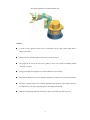
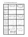
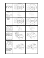
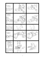
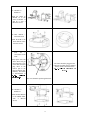
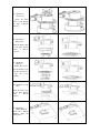
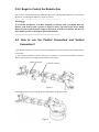
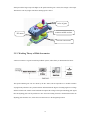
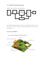
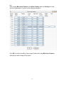
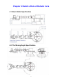
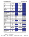
Joinmax
Robotic Arm Kit
Assembly Manual
Version 1.3
Contents
CHAPTER 1 BRIEF INTRODUCTION......................................................................................3
1.1. WHAT IS JOINMAX ROBOTIC ARM? ............................................................................................3
1.2. PARTS LIST ..................................................................................................................................5
CHAPTER 2 HOW TO ASSEMBLE IT? ....................................................................................6
2.1. PREPARE TO WORK .....................................................................................................................6
2.1.1. TOOLS REQUIRED.................................................................................................................... 6
2.1.2. ABOUT THE POWER SUPPLY ................................................................................................... 6
2.2. ASSEMBLY PARTS LIST(INCLUDING ACCESSORIES).....................................................................7
2.3. ASSEMBLY STEPS .......................................................................................................................9
2.3.1 THE DETAILED ASSEMBLY PROCESSES ....................................................................................10
2.3.2. BEGIN TO CONTROL THE ROBOTIC ARM ...............................................................................16
2.4. HOW TO USE THE PARALLEL CONNECTORS AND VERTICAL CONNECTORS?.............................16
CHAPTER 3 HARDWARE DESCRIPTION.............................................................................17
3.1. BASIC KNOWLEDGE OF MINI-SERVOMOTOR ............................................................................17
3.1.1. BRIEF INTRODUCTION OF MINI-SERVOMOTOR ......................................................................17
3.1.2. INTERNAL STRUCTURE OF MINI-SERVOMOTOR .................................................................... 17
3.1.3. WORKING THEORY OF MINI-SERVOMOTOR.......................................................................... 18
3.1.4. HOW TO CONTROL SERVOMOTOR......................................................................................... 19
3.1.5. POWER SUPPLY WIRES OF SERVOMOTOR .............................................................................. 20
3.1.6. THE SPEED OF SERVOMOTOR................................................................................................ 20
3.1.7. NOTICES FOR SERVOMOTOR USAGE ..................................................................................... 20
3.2. JM-SSC16 SERVOMOTORS CONTROL BOARD DESCRIPTION ...................................................21
3.2.1. WHAT IS THE JM-SSC16 .......................................................................................................21
3.2.2. SPECIFICATIONS OF JM-SSC16............................................................................................. 21
3.2.3. JM-SSC16 WORKING ENVIRONMENTS ................................................................................ 22
3.2.4. PORTS OF JM-SSC16 ............................................................................................................ 22
3.2.5. CONNECTING CABLE BETWEEN JM-SSC16 AND PC SERIAL PORT ...................................... 24
3.2.6. RS232 COMMUNICATION PROTOCOL OF JM-SSC16 ............................................................ 24
3.3. BRIEF INTRODUCTION OF MINI SERVO EXPLORER ...................................................................25
CHAPTER 4 RELATIVE DATA OF ROBOTIC ARM ............................................................27
4.1. BASIC STATIC SPECIFICATION ...................................................................................................27
4.2. THE MOVING ANGLE SPECIFICATION .......................................................................................27
2
Chapter 1 Brief Introduction
Congratulations on your smart purchasing of the Robotic Arm Kit delivered by Joinmax Digital Tech. This
kit will be sure to satisfy your desire for robotic study no matter you are a newcomer or a seasoned veteran.
This kit includes a complete set of the electronic and mechanical parts and basic control software. It will
take you about 2 hours to set up a complete lively Robotic Arm according to the user manual, and base on
it, you will be able to bring your imagination and creativity into play.
To acquaint yourself with the excellent property of the Robotic Arm and its correct assembling and control
method, you are strongly proposed to read this manual carefully. If you have any comment or suggestion,
please send us a letter or email through our web site, and it’s address is http://www.robotplayer.com.
We' d love to he
ar from you. Your suggestion will be very helpful to the improvement of our
robots.
If you have a good project of playing the Robotic Arm, please don’t hesitate to send us the jpg images and
some necessary descriptions of it, we will publish them on our web site so that more players can share your
success and joy.
1.1. What is Joinmax Robotic Arm?
The Joinmax Robotic Arm is a typical robotic arm model which is usually used to stimulate actions of
human arm and is a basic platform for the study purpose of various robotic arms, and can be applied in
many fields such as research, education, entertainment etc. and it is also a good tool to expand your view
and enhance your ability. You need to assemble the Robotic Arm by yourself, and you should use more
than 100 parts in it, this will challenge your intellect and handwork ability, but you will experience the
pleasure through assembly and testing it. Through the software’s control, the Hexapod Monster will be able
to simulate various behaviors of animals, and that will make the science theory visualizes more.
3
The global appearance of Joinmax Robotic Arm
Features:
It is able to move flexibly because it has 7 Servomotors for the joints control which forms 6
degree of freedom.
Each joint servo could be parallel connected or vertical connected.
The gripper at the end of the arm can be jointed to servo with 3 kinds of methods: parallel,
vertically, or rotated.
Using gear design for the gripper let it stretch and deliver object flexibly.
With built-in standard AA/5 size rechargeable batteries box inside, let the arm work stand alone.
Driven by a general purpose servo controller board with open protocol, let this smart arm easy to
be controlled by your own designed program or extending control board.
With two rotating angle indicators on the base, make your control work more precisely.
4
1.2. Parts list
1.
45 Precise plastic items and 66 metallic parts, the total is 111 separate parts
2.
1 Mini servo controller board
3.
7 servomotors
4.
4 Extended Cables for Motor
5.
1 Joinmax Mini Servo Explorer CD for installation
6.
1 computer connecting cable
7.
1 battery cable
8.
1 assembly manual(You’re reading it)
5
Chapter 2 How to Assemble It?
2.1. Prepare to work
2.1.1. Tools required
Before assemble the Robotic Arm, you must prepare the following tools:
(1) 1 cross screwdriver
(2) 1 tip pincers
2.1.2. About the Power Supply
The Robotic Arm needs strong power supply. Its voltage is about 5 to 6 volts, so we suggest you to choose
5 rechargeable batteries which voltage is 1.2 volts, each with large capacity and good quality. For instance,
prepare 5 1800mAh Ni-H (AA/5 size) rechargeable batteries. At the same time you should prepare a good
quality battery charger, which can be bought in the market easily. It can save your money because you can
use these batteries repeatedly.
WARNING!
1
Don’t use normal alkaline battery which voltage is 1.5 volts, and it will do harm to the electrics
circuit of Hexapod Monster.
2
Don’t use any inferior or easy leakage batteries because any damages caused by batteries misuse
are not covered under our guarantee.
3
Remember to use the batteries at least after 15 minutes after they are completely charged,
otherwise it may hurt the control circuit because of unstable voltage.
6
2.2. Assembly parts List(including accessories)
You will use the following parts in the assembly process, please array them one by one.
1.Base Bottom
(1PCS)
2.Dial
(1PCS)
3.Base Top
(1PCS)
4.Battery Box
(1PCS)
5.Battery Box Cover
(1PCS)
6. Fore Cover
(1PCS)
7.Back Cover
(1PCS)
8.Midlle Pillar
(1PCS)
9.Computer Connecting
Cable (1PCS)
10.Nylon Rope
(6PCS)
11.Extended Cable for
Motor (4PCS)
12.Slip Board
(1PCS)
13.Servo Motor
(7PCS)
14.Connector-1
(3PCS)
15.Connector-2
(3PCS)
16.Parallel Connector
(1PCS)
17.Vertical Connector
(4PCS)
18.Roatator
(1PCS)
19.Battery Cable
(1PCS)
20.Clamp Bottom
(1PCS)
21.Clamp Top
(1PCS)
22.Left Clamp
(1PCS)
23.Right Clamp
(1PCS)
24.Motor Cover
(1PCS)
7
25.Turning Arm-1
(1PCS)
26.Turning-2
(1PCS)
27.Fixing Hoop
(1PCS)
28.Controller Board
(1PCS)
29.Screw M2.5x6
(36+1PCS)
30.Screw M2.5x10
(2+1PCS)
31.Screw M2.5x18
(3+1PCS)
32.Screw M2.8x8
(2+1PCS)
33.Bolt M3x20
(6PCS)
34.Nut M3
(6PCS)
35.Ball Bearing
(5+1PCS)
36.Axis
(5+1PCS)
37.Fixing Seat
(1PCS)
38.Mini Server Explorer CD
(1PCS)
39.Assemly Manual
(1PCS)
8
2.3. Assembly Steps
We suggest you to check up the types and quantities of all parts first, and then you had better follow the
illustrations below strictly to assemble the Robotic Arm, and pay attention to the relative warning.
The parts of Robotic Arm include two parts, one of them is the selection parts, and the other is movable
parts which are used to form 6 degrees of freedom and deployed to 7 servomotors (Two of them use the
same axis) and they are Connectors (3 pieces), Vertical Connectors (4 pieces), Parallel Connector (1 piece)
and Rotator (1 piece), and through different combinations of them, you can induce various assembly
method. In narrow sense, you can assemble the clamp in 12 ways when calculated on 6 degrees of freedom,
but in broad sense, you can assemble it in 96 ways in the same calculation method. But if you decrease or
increase degrees of freedom to calculate, you can induce more assembly methods. Which method will be
chosen to assemble it depends on your requirement. The assembly process demonstrated below is a typical
assembly method.
No.6 servomotor
No.1 servomotor
Right Clamp
Fore Cover
No.4 servomotor
Back Cover
No.7 servomotor
No.2 servomotor
Electronic
Control Board
No.3 servomotor
No.5 servomotor
Rotator
Base
Bottom
Connecting Arm
Battery Box
The Typical Assembly Drawing (The main parts are listed)
WARNING: If NO.1~NO.4 Servomotor’s length is less than 50cm, please extend it with the
Extended cable for motor.
9
2.3.1 The detailed assembly processes
1. Base Top + Middle
Pillar + Screws
(Use 4 M2.5x6 screws
to fasten the Base Top
to the Middle Pillar
according
to
the
drawing.)
2. Ball Bearing +
Axis
(Harness the ball
bearing to the Axis
according
to
the
drawing, the total is 5
PCS.)
3. Module1+
Module2
(Embed the module2
into the square slot of
the Base Top, the total
is 3 PCS)
4. Use a wire cutter
or a saw to cut the
outstanding part
of
No.7
servomotor
to
avoid it blocking
the wire of the
other servomotors,
don’t cut the other
servomotors.
The outstanding part of the servomotor
before being cut.
5. Module 3 + Dial+
No.7 servomotor
+ screws
(Put the Dial onto the
Base Top, and put the
servomotor into the
slot of the Dial, make
sure that the gears of
the servomotor and
the Base Top link
well, and then firm
the servomotor with
4 M2.5x6 screws.)
10
The outstanding part of the servomotor
after being cut.
6. Module 5 +screws
(Firm the Base Top to
the axis of the
servomotor with a
black M2.8x8 screw.)
7. Slip board +
Module 2
(Embed the module2
into the square slot of
the slip board)
8. Module 6 +
Module 7
(Firm the Slip board to
the Dial with 2
M2.5x6 screws)
9. Turning arm 2 +
No.6 servomotor
(Insert the Turning
Arm into the axis of
No.6 servomotor, and
keep them link well)
10. Module 8 +
Module 9
(Put No.5 and No.6
servomotor into a big
square slot in the Dial.
The two servomotors
should be put in a
same place perfectly,
because they should
move synchronously.)
11. Module 10 +
Turning Arm 1+
No.4 servomotor
(Before install the
No.4 Motor, Please
find
the
phase
difference of No.5 and
NO.6 Motor)
(Put the Turning
Arm1into the Turnin
Arm 2, and embed the
No.4 servomotor
between them, then
firm it with a black
M2.8x8 screw)
11
12. Module 11 +
Fore Cover
(Firm the Fore Cover
onto the Dial with 7
M2.5x6 screws)
13. Module 12+
Connector 1+
Connector 2
(Harness
the
Connector1,
Connector2 and No.3
servomotor together
each other, and link
them to the Module
12.
14. No.2 Servomotor
+ Cover
(Take off the cover of
the No.2 servomotor
and replace it with a
special cover.)
15. Module 13 +
Module 14
(Connect Module 14
and Module 13 with
the Connector 1 and
Connector 2)
16. Clamp Top +
Clamp Bottom +
Left Clamp +
Right Clamp +
No.1 servomotor
+ Fixing Hoop
+ Rotator+ Nut
+ Bolt
(Assemble all the parts
above, and firm them
with tow Bolts and
Nuts.
12
17. Module 15 +
Module 16
(Firm the rotator of
Module 16 to the
waist of Module 15
and fix it with 2
M2.5x10 screws)
18. Base Bottom +
Electronic PCB
(Firm the PCB to the
Base Bottom with 4
M2.5x6 screws)
19. Connect the wires
from
the
7
servomotors to the
PCB
(Tidy up the wires and
fasten them and put
them through a hole
in the Dial, and then
plug them to the
relative pins in the
PCB according their
numbers, The details
is demonstrated in
!"
The wires should be plugged to the
right pins according to their numbers
strictly which is demonstrated in
“#$&%$'$ (*) + ,,-/.0213456789 5 ” :;
<=>?@A&B
The wires should be put through this hole.
20. Module 17 +
Module 18
(Firm the Base Bottom
to the Middle Pillar
with
4
M2.5x6
screws)
13
21. Module 20+
Back Cover
Firm the Back
Cover to the Module
20 with 4 M2.5x6
Screws
22. Module 21 +
Battery Box
(Firm the Battery Box
to the Base Bottom
with
4
M2.5x6
screws)
23. Module22+
Batteries+
Battery Box Cover
(Put the Batteries into
the Box and cover it
with
the
Cover
tightly.)
24. Module23+ Fixing
Seat
(Firm the Fixing Seat
to the Base Bottom
with
3
M2.5x6
screws)
25. Module24+
Rubber Washers
(Paste the 4 Rubber
Washers under the
Fixing Seat)
14
26. Module25+
Screws
(Firm the turning arms
and connectors with 3
M2.5x18 screws)
15
2.3.2. Begin to Control the Robotic Arm
After you have connected servomotors and Battery Box to the control PCB through wires, you can control
the Robotic Arm through the Mini Servo Explorer software.
--------------------------------------------------------------------------------------
Warning
To avoid that the Robotic Arm hurt somebody or damage itself, you should make the
Robotic Arm stand at such a gesture as Figure 2 before you turn on the power supply
button, because when the power supply is turned on, all of the servomotors will move to
their middle position at the highest speed and suddenly.
---------------------------------------------------------------------------
2.4. How to use the Parallel Connectors and Vertical
Connectors?
1 The Parallel Connectors are used to connect the head and the servomotor and keep them stands vertically
to each other.
2 The Vertical Connectors are used to connect two servomotors or connect the head and the servomotor,
which can be used to keep the angle between them to be 90 degree.
Parallel Connector
Vertical Connector
Figure 1
The parallel connectors are used in the head as demonstrated in the figure below:
Figure 2
16
Chapter 3 Hardware Description
3.1. Basic Knowledge of Mini-Servomotor
3.1.1. Brief introduction of Mini-Servomotor
Many people think it is very difficulty to make a robot. But in fact, making a personal robot is not more
difficult than making a car model, further more it will enable you to experience another kind of pleasure,
expand your view, and elicit your inspiration.
In the following we will introduce briefly the working theory and controlling way of the mini-servomotor
which is the most comment intelligent part for personal robot.
Mini-servomotor has been used quite widely in radio amateurs’ models for a long history. It is a main part
for controlling the moving directions. Servomotor is a kind of motor used for positioning which is able to
move to the designated position after receiving an order. So it is used to control the joints in the robot
model, and we call these joint the degree of freedom.
The servomotor has the following advantages: large torque, easy control, flexible assembly, inexpensive.
But it also has some disadvantages: firstly, it is an precise machine, which will be damaged when being
overloaded. Secondly, there is an electronics control circuits inside, which will be destroyed by incorrect
connecting. So it is necessary to understand how their works before we use them to avoid losses.
The servomotors displayed in the pictures of this manual are Vigor’s servomotors which designed for robot
model usages specially and they have many advantages: large torque force, good performance, lower price
etc, and are suitable for robot amateurs usages.
3.1.2. Internal structure of Mini-Servomotor
A servomotor is constructed by a small D.C. motor, a gear case, a feedback resistance for adjustment
purpose and an electronic control board. The high speed D.C. motor provides original power to the gears
17
which provide the large torque. The higher is the speed ration the gears’ convert, the stronger is the torque.
That means it can carry higher load but its turning speed is slower.
series of gears
Feedback variable resistor
DC motor
electronic control board
3.1.3. Working Theory of Mini-Servomotor
A mini-servomotor is a typical closed loop feedback system, and its theory is demonstrated as below:
The speed reduction gears case are driven by the D.C motor, and its output drives a variable resistance
varying linearly which acts as a position detector and transforms the degrees of turning angle into a voltage
and feed it back to the control circuit board which compares the voltage to the input controlling pulse signal,
then an adjusting pulse will be produced to drive the motor turning forward or backward and make the
adjusting pulse becomes zero, so that the servomotor moves to the designated position.
18
3.1.4. How to Control Servomotor
A standard mini-servomotor has three control wires which is power, GND and control line. The power wire
and GND are used to supply the power to the D.C. motor and the control circuit. The power should be
between 4V-6V and separated from the one of processing system because the servomotor will cause high
frequency noise and sometimes, even a small servomotor can lower the voltage of the amplifier when it is
loaded highly, so the configuration of the power supply should be reasonable.
Normally, the servomotor requires a high pulse of 1ms to 2ms in period and a low pulse of 5ms to 20ms in
period which is not very strict. The illustration below demonstrates the relationship between the pulse
length and the mini-servomotor output shaft position, the period of pulse is 20ms.
Input pulse width (T=20MS)
Servo position
0.5ms
- 90º
1.0ms
- 45º
1.5ms
0º
2.0ms
45º
2.5ms
90º
19
3.1.5. Power Supply wires of Servomotor
Control Wire (Yellow)
SERVO Power (Red)
GND (Black)
The yellow one is control wire which should be connected to control chip. And the middle one is power
supply wire, and the power is usually 5 volt. And the third one is GND.
3.1.6. The Speed of Servomotor
The instant speed of servomotor depends on the coordination between the internal D.C. motor and the gears
and remains unchanged under a constant driving voltage. But its average speed can be changed by inserting
stop points between the start position and the designated position. For example, we can divide a distant of
90 degrees into 128 stop points, and lengthen the stop time in each stop points to slow down the average
speed of servomotor because to most servomotors, the unit of the speed is “degrees/second”.
3.1.7. Notices for Servomotor Usage
C
C
The shaft position of servomotor is not so accurate unless it is a digital servomotor.
The normal servomotors are not precise positioning devices, and the differences between them
vary largely, even they are of
C
servomotors have
the same brand or model. So it is normal that different
10 degrees deviation under the same driving pulse.
Because of the mention above, it is not recommended that don’t use a driving pulse less than 1ms
or larger than 2ms. And in fact, the turning range of servomotor original designed is within 45
D
because the linear relationship between the pulse length and the turning angle will become
20
worse when the turning angle exceed
F
45E .
Warning: Do not use a pulse which will drive the servomotor turn out of
90 E
range.
Otherwise, the servomotors mechanical stop or the gears will be damaged.
F
There is no standard for servomotors output shaft degrees and control pulse length, so you need
to adjust the parameters in the control software based on different servomotors.
3.2. JMSC16 Servomotors Control Board Description
3.2.1. What is the JM-SSC16
JM-SSC16 is a control board for general purpose which is able to control up to 16 servomotors through the
serial ports of PC. It can be connected to PC or other control systems through communication cable. You
can control up to 16 mini-servomotors to move through simple programming and you can download a
series of parameters about the motion and enable the robot moves without being connected to the
controlling PC.
3.2.2. Specifications of JM-SSC16
F
F
MPU
AVR Series Atmega16
F
Serial Port
RS232
9600
N81
F
Output Ports to Servomotors
F
Suitable Servomotors
F
Output Pulse
F
PCB Size
VIGOR
FUTABA and HITEC
T=20MS VH=0.5~2.5MS
Turning Range: 0
F
16 channels of Ports
180
53×60mm
Power Supply
+5V For Logical Circuit +6V For Servomotor
21
GND
3.2.3. JM-SSC16 Working Environments
JM-SSC16 working environments are demonstrated as below:
The
Up
driving
servomotor
to
16
machine
JM-SSC16
PC
Servomotor
MCU
control board
control
of robot
or
sensors
main
board
Power supply
Power supply: Includes the power supply of the control system (+5 volts) and that of servomotor (+6 volts).
If you want to use only one power supply, you must keep the voltage between 5.0 volt and 5.5 volt, and
short the jumper J4.
3.2.4. Ports of JM-SSC16
G
All the ports of JM-SSC16 are demonstrated as below:
22
H
Pinouts on JM-SSC16
NOTE
You must set an ID number to the control board before it is used. The ID number
should be NO.1 if you use only one board, The DIP switch setting for NO.1 is shown as
below:
DIP switch (NO.)
ON
OFF
1
2
3
4
There are two operation modes for the Mini-servo Control Board:
Operation Mode
Condition
Operation
On-line mode
1. It’s connected to the PC It’s on-line controlled by
RS232 port via download Mini-servo Explorer program.
cable.
2. Mini-servo Explorer has
been run on the above PC.
Off-line mode
1. No cable is connected to It will run the actions which
its RS232 serial port.
being edited and downloaded
2. 4 seconds after powered on by Mini-servo Explorer at the
or being reset.
last time.
23
3.2.5. Connecting Cable between JM-SSC16 and PC Serial Port
Specification of the cable:
Pins to Pins table
DB9F Connector PC Serial Port
RJ11 Connector Robot Serial Port
DB9F 5
RJ11 1 -GND
DB9F 2
RJ11 2 -TXD
DB9F 3
RJ11 3 -RXD
DB9F 5
RJ11 4 -GND
3.2.6. RS232 Communication Protocol of JM-SSC16
There are two communication protocols: Instant control protocol and download protocol.
I
Instant Control Protocol
Byte Number
1
2
3
Meaning
0xff
Servomotor
Number(0~n)
Servomotor
Parameter(0~253)
The first byte is a marking byte, and the second byte is a number of servomotors which is defined by
customer himself, and each of them is mapped to their relative position in the control software one by one.
The third byte is the numbers of servomotor parameters which is used control the positions of servomotors.
For example, the value of first byte is 0XFF the data of the third byte is used for instant control which will
24
be stored into the area of instant data in the CPU.
3.3. Brief Introduction of Mini Servo Explorer
Mini Servo Explorer is the specially designed control software based on Windows for JM-SSC16 which
has many good features such as visible interface, easy to operate, and they will be demonstrated as below:
1
The upper limit and the lower limit of servomotors can be set separately according to the parameters
or environmental conditions of each servomotor.
2 You can control any servomotor in the system separately, and make them work separately or work
together harmoniously.
3 You can make the servomotor move to the designated position at the highest speed, or you can make
it move smoothly to there by setting its speed factor.
4 The servomotor can be controlled by inputting the value of position or drawing scrollbar on the
interface.
5 The graphical user interface is friendly and is easy to operate, and the software also provides many
useful functions.
6 You can modify the unsatisfied actions of the robot while you are playing it, and you can also edit the
actions in the PC without connecting robot.
7 It is very convenient to modify the actions of the robot because you can store the edited actions for
later usage or link up many separate actions into a complete set of actions.
8
The software has many powerful functions, and lively samples.
Please read the manual or online help of Mini Servo Explorer for more details.
Mini-servo Explorer setting for Smart Arm
Because NO.5 servomotor and NO.6 servomotor must rotate at the same angle at all
time, You must set the motor6 as a slave motor in the Servo motor setting dialog
25
box.
After running Mini-servo Explorer, click Motor Setting under the Setting menu bar
and set the parameter of motor6 as the following dialog box.
Click OK to confirm the setting. Other usage Please refer to the Mini-Servo Explorer
software user book or help file for details.
26
Chapter 4 Relative Data of Robotic Arm
4.1. Basic Static Specification
4.2. The Moving Angle Specification
27