1
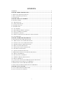
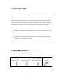
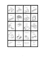
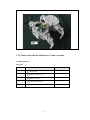
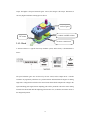
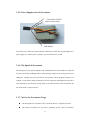
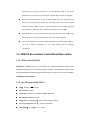
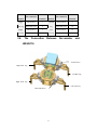
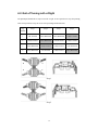
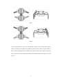
JOINMAX DIGITAL
QUADRUPED
ROBOT KIT
Assembly Manual Version 1.2
1
CONTENTS
CONTENTS ..................................................................................................................................... 2
CHAPTER 1 BRIEF INTRODUCTION...................................................................................... 3
1.1. WHAT IS THE JOINMAX QUADRUPED?........................................................................................ 3
1.2. WHY TO ASSEMBLE QUADRUPED?............................................................................................. 5
1.3. PACKAGE LIST ............................................................................................................................ 5
CHAPTER 2 HOW TO ASSEMBLE? ......................................................................................... 5
2.1. PREPARE TO WORK .................................................................................................................... 5
2.1.1. REQUIRED TOOLS .................................................................................................................... 5
2.1.2. ABOUT POWER SUPPLY ........................................................................................................... 6
2.2. ASSEMBLY PARTS LIST ............................................................................................................... 6
2.3. ASSEMBLY STEPS ....................................................................................................................... 8
2.3.1. LEG ASSEMBLY ....................................................................................................................... 8
2.3.2. BOTTOM BOARD MODULE ASSEMBLY .................................................................................. 11
2.3.3. TOP COVER MODULE ASSEMBLY .......................................................................................... 11
2.3.4. MAIN BODY ASSEMBLY ........................................................................................................12
2.3.5. MAIN CONTROL BOARD AND BATTERY CABINET ASSEMBLY ...............................................15
2.3.6. LOAD BATTERIES ..................................................................................................................17
CHAPTER 3 HARDWARE DESCRIPTION ............................................................................ 18
3.1. BASIC KNOWLEDGE OF MINI-SERVOMOTOR ............................................................................ 18
3.1.1. BRIEF INTRODUCTION OF MINI-SERVOMOTOR ...................................................................... 18
3.1.2. INTERNAL STRUCTURE OF MINI-SERVOMOTOR .....................................................................18
3.1.3. WORKING THEORY OF MINI-SERVOMOTOR .......................................................................... 19
3.1.4. HOW TO CONTROL SERVOMOTOR ......................................................................................... 20
3.1.5. POWER SUPPLY WIRES OF SERVOMOTOR ...............................................................................21
3.1.6. THE SPEED OF SERVOMOTOR ................................................................................................ 21
3.1.7. NOTICES FOR SERVOMOTOR USAGE ...................................................................................... 21
3.2. JMSC16 SERVOMOTORS CONTROL BOARD DESCRIPTION ....................................................... 22
3.2.1. WHAT IS THE JM-SSC16 ....................................................................................................... 22
3.2.2. SPECIFICATIONS OF JM-SSC16 ............................................................................................. 22
3.2.3. JM-SSC16 WORKING ENVIRONMENTS .................................................................................23
3.2.4. PORTS OF JM-SSC16............................................................................................................. 23
3.2.5. CONNECTING CABLE BETWEEN JM-SSC16 AND PC SERIAL PORT ....................................... 24
6. RS232 COMMUNICATION PROTOCOL OF JM-SSC16................................................................... 25
3.3. BRIEF INTRODUCTION OF MINI SERVO EXPLORER ................................................................... 26
3.4. THE CONNECTION BETWEEN SERVOMOTOR AND JM-SSC16 ..................................................27
CHAPTER 4 GAIT ANALYSIS.................................................................................................. 28
4.1. GAIT OF GOING FORWARD OR BACKWARD ..............................................................................28
4.2. GAIT OF TURNING LEFT OR RIGHT ...........................................................................................30
2
Chapter 1 Brief Introduction
Congratulations on your smart purchasing of the Quadruped robot kit delivered by Joinmax
Digital Tech. This kit will be sure to satisfy your desire for robotic study no matter you are a
newcomer or a seasoned veteran.
This kit includes a complete set of the electronic and mechanical parts and basic control software.
It will take you about 2 hours to set up a complete lively Quadruped according to the user manual,
and base on it, you will be able to bring your imagination and creativity into play.
To acquaint yourself with the excellent property of the Quadruped Monster and its correct
assembling and control method, you are strongly proposed to read this manual carefully. If you
have any comment or suggestion, please send us a letter or email through our web site, and its
address is http://www.robotplayer.com. We'd love to hear from you. Your suggestion will
be very helpful to the improvement of our robots.
If you have a good case of playing the Quadruped Monster, please don’t hesitate to send us the jpg
images and some necessary descriptions of it, we will publish them on our web site so that more
players can share your success and joy.
1.1. What is the Joinmax Quadruped?
The Joinmax bionic Quadruped Monster is a typical model for robot walking gait study, and it is a
basic platform of walking robot. It can be applied in many fields such as research, education,
entertainment etc. and it is also a good tool to expand your view and enhance your ability. You
need to assemble the Quadruped Monster by yourself, and you should use more than 170 parts in
it, this will challenge your intellect and handwork ability, but you will experience the pleasure
through assembly and testing it. Through the software’s control, the Quadruped Monster will be
able to simulate various behaviors of animals, and that will make the science theory visualizes
more.
The global appearance of Joinmax Quadruped Monster
3
Figure 1
Features:
It is able to move flexibly because it has 8 Servomotors for the joints control.
It is able to run fast because it has 4 Strong Legs lifting vertically and Turning
horizontally.
The gripper mounted on its head is able to clamp and deliver objects easily.
It is high expansible because it adopts a general-purpose servo control PCB.
It is easy to upgrade to 6 legs or 8 legs robot by adding parts.
Through controlling its 8 servomotors precisely, it is able to simulate various walking gaits of the
hexapod animals, such as rambling, quick walking, fast running, turning, spinning, etc. and is able
to adjust its gaits to adapt different ground environments such as smooth ground, rough ground,
sandy ground, or wet ground.
It is even enable to do many A.I behaviors by means of the control circuit board.
4
1.2. Why to Assemble Quadruped?
Through assembling the Joinmax Quadruped by yourself, you will be acquainted with the
mechanical theory of walking, you will also learn how to control servo motor and operate software,
and then you can master the skills to enable the Quadruped Monster to walk.
1.3. Package List
1.
42recise plastic modules and 40etallic parts, the total is 82eparate parts
2.
1 Mini servo controller board that can control up to 16 servomotors.
3.
8 precise servo motors.
4.
1 Joinmax Mini Servo Explorer CD for installation
5.
1 computer connecting cable
6.
1 battery cable
7.
1 assembly manual(You’re reading it)
Chapter 2 How to Assemble?
2.1. Prepare to Work
2.1.1. Required Tools
Before assemble the Quadruped, you must prepare the following tools:
1
1 cross screwdriver
2
1 tip pincers
5
2.1.2. About Power Supply
Quadruped needs strong power supply which voltage is about 5 to 6 volts, so we suggest you to
choose 5 rechargeable batteries which voltage is 1.2 volts each with large capacity and good
quality.
Please prepare 5 GP 1800mAh Ni-H AA/5 rechargeable batteries. At the same time you should
prepare a good quality battery charger, for example, the “GP battery charger” which can be bought
in the market easily. It can save your money because you can use these batteries repeatedly.
WARNING!
1
Don’t use normal alkaline battery which voltage is 1.5 volts, and it will do harm to the
electrics circuit of Hexapod Monster.
2
Don’t use any inferior or easy leakage batteries because any damages caused by batteries
misuse are not covered under our guarantee.
3
Remember to use the batteries at least after half an hour after they are completely charged,
otherwise it will hurt the control circuit because of high voltage.
2.2. Assembly parts List
You will use the following parts in the assembly process, please array them.
1
M2.5×18 Tapping
2 M2.5×10 Tapping
Screw TS1(8 Pieces)
3
Screw TS2(24 Pieces)
.5×6 Tapping
Screw TS3 (8 Pieces)
6
4
Long Leg (4
Pieces)
5
Servo hoop (4
6
Upper Limb A (4
Pieces)
9
Lower Limb B (4
Turning Board (4
Upper Limb B (4
Pieces)
10
Pieces)
13
7
Lower Limb A (4
Pieces)
Top Cover (2
11
Bottom Board (2
Pieces)
14
8
Pieces)
12 Connecting Board
Pieces)
Waist (2 pieces)
15
pieces)
Battery cabinet
(2 pieces)
16
cover (1
Battery Cabinet
(1 Piece)
pieces)
17
Servomotor
18 Main Control Board
19 Servomotor turning
(1
arm (4 Pieces)
(8Pieces)
20
to battery
(1 piece)
Piece)
21 connecting cable
23 Joinmax mini-servo
22
of
wire connected
24
Assembly manual
computer
nylon cable
Explorer software
button
(1 Piece)
(1 piece)
CDrom (1 Piece)
(5 piece)
you’re reading
7
2.3. Assembly Steps
We suggest you to check up the types and quantities of all parts first, and then you had better
follow the illustrations below strictly to assemble the Quadruped Monster, and pay attention to the
relative warning.
2.3.1. Leg Assembly
Assembly Quantity
2 Right Legs and 2 Left Legs
Parts List (For each leg):
No.
Part name
Quantity
No.
Part name
Quantity
1
2
M2.5×10 TS2
6
6
9
2
4
Long Leg
1
7
13
Turning Board
1
3
6
Upper Limb A
1
8
17
Servomotor
1
4
7
Upper Limb B
1
9
19
Servomotor turning
1
Lower Limb B
1
arm
5
8
Lower Limb A
1
WARNING:
Make all the screws face to same direction for better appearance.
Pay attention to the assembly direction of “(10) Lower Limb A” (Illustration 3). There is a
deeper hole at one side, you had better make the screw cap sink inside the hole, and face
outside when assemble. The wrong fixing will affect the activity of the whole leg.
8
Right Leg Assembly Steps
1
2
3
4
5
6
7
8
9
Left Leg Assembly Steps
1
2
3
4
5
6
7
8
10
2.3.2. Bottom Board Module Assembly
Assembly Quantity
Parts List
2
No.
Part Name
Quantity
2
1
5
Servo hoop
2
11
Bottom Board
1
3
17
Servomotor
2
4
Left Leg Module
1
5
Right Leg Module
1
Assembly Steps
1
2
2.3.3. Top Cover Module Assembly
Assembly Quantity: 1
Parts List
No.
Part Name
QUANTITY
1
(10) Top Cover
2
2
(14)Waist
1
3
(12) Connecting Board
2
11
Assembly Steps
1
2
2.3.4. Main Body Assembly
Assembly Quantity: 1
Parts List:
No.
Part Name
Quantity
1
(1)M2.5X18 TS1
8
2
(14)waist
1
3
Top Cover Module
1
4
Bottom Board Module
2
12
Assembly Steps
1
Before you put the waist into the anchor slot on the top cover, please install all connecting lines of the
servomotors into the line pipe of the waist first, let all the lines pass through the hole on the top cover as
below and then pack up the cables with nylon cable button. .
13
2
Before assembly, you had better let the connecting lines of servomotor pass through the holes of the
cover and bottom board as below.
14
3
2.3.5. Main Control Board and Battery Cabinet Assembly
Assembly Quantity: 1
Parts List:
No.
Part Name
Quantity
1
3
2
15
Battery Cabinet Cover
1
3
16
Battery Cabinet
1
4
18
Main Control Board
1
5
M2.5X6 TS3
8
Main Body
1
15
Assembly Steps
1
2
16
2.3.6. Load Batteries
1
2
Load 5 AA/Size rechargeable batteries in the
cabinet as above, the poles should be in
accordance with the illustration.
3
4
Close and lock the cover
Now, you have completed assembly of Quadruped.
17
Chapter 3 Hardware Description
3.1. Basic Knowledge of Mini-Servomotor
3.1.1. Brief introduction of Mini-Servomotor
Many people think it is very difficulty to make a robot. But in fact, making a personal robot is not
more difficult than making a car model, further more it will enable you to experience another kind
of pleasure, expand your view, and elicit your inspiration.
In the following we will introduce briefly the working theory and controlling way of the
mini-servomotor which is the most comment intelligent part for personal robot.
Mini-servomotor has been used quite widely in radio amateurs’ models for a long history. It is a
main part for controlling the moving directions. Servomotor is a kind of motor used for
positioning which is able to move to the designated position after receiving an order. So it is used
to control the joints in the robot model, and we call these joint the degree of freedom.
The servomotor has the following advantages: large torque, easy control, flexible assembly,
inexpensive. But it also has some disadvantages: firstly, it is an precise machine, which will be
damaged when being overloaded. Secondly, there is an electronics control circuits inside, which
will be destroyed by incorrect connecting. So it is necessary to understand how theyr works before
we use them to avoid losses.
The servomotors displayed in the pictures of this manual are Vigor’s servomotors which designed
for robot model usages specially and they have many advantages: large torque force, good
performance, lower price etc, and are suitable for robot amateurs usages.
3.1.2. Internal structure of Mini-Servomotor
A servomotor is constructed by a small D.C. motor, a series of gears, a feedback
potentiometer (variable resistor) for position adjustment purpose and an electronic control
board. The high speed D.C. motor provides original power to the gears which provide the large
18
torque. The higher is the speed ration the gears’ convert, the stronger is the torque. That means it
can carry higher load but its turning speed is slower.
series of gears
Feedback variable resistor
DC motor
electronic control board
3.1.3. Working Theory of Mini-Servomotor
A mini-servomotor is a typical closed loop feedback system, and its theory is demonstrated as
below:
The speed reduction gears case are driven by the D.C motor, and its output drives a variable
resistance varying linearly which acts as a position detector and transforms the degrees of turning
angle into a voltage and feed it back to the control circuit board which compares the voltage to the
input controlling pulse signal, then an adjusting pulse will be produced to drive the motor turning
forward or backward and make the adjusting pulse becomes zero, so that the servomotor moves to
the designated position.
19
3.1.4. How to Control Servomotor
A standard mini-servomotor has three control wires which is power, GND and control line. The
power wire and GND are used to supply the power to the D.C. motor and the control circuit. The
power should be between 4V-6V and separated from the one of processing system because the
servomotor will cause high frequency noise and sometimes, even a small servomotor can lower
the voltage of the amplifier when it is loaded highly, so the configuration of the power supply
should be reasonable.
Normally, the servomotor requires a high pulse of 1ms to 2ms in period and a low pulse of 5ms to
20ms in period which is not very strict. The illustration below demonstrates the relationship
between the pulse length and the mini-servomotor output shaft position, the period of pulse is
20ms.
Input pulse width (T=20MS)
Servo position
0.5ms
- 90º
1.0ms
- 45º
1.5ms
0º
2.0ms
45º
2.5ms
90º
20
3.1.5. Power Supply wires of Servomotor
Control Wire (Yellow)
SERVO Power (Red)
GND (Black)
The yellow one is control wire which should be connected to control chip. And the middle one is
power supply wire, and the power is usually 5 volt. And the third one is GND.
3.1.6. The Speed of Servomotor
The instant speed of servomotor depends on the coordination between the internal D.C. motor and
the gears and remains unchanged under a constant driving voltage. But its average speed can be
changed by inserting stop points between the start position and the designated position. For
example, we can divide a distant of 90 degrees into 128 stop points, and lengthen the stop time in
each stop points to slow down the average speed of servomotor because to most servomotors, the
unit of the speed is “degrees/second”.
3.1.7. Notices for Servomotor Usage
The shaft position of servomotor is not so accurate unless it is a digital servomotor.
The normal servomotors are not precise positioning devices, and the differences
21
between them vary largely, even they are of the same brand or model. So it is normal
that different servomotors have
10 degrees deviation under the same driving pulse.
Because of the mention above, it is not recommended that don’t use a driving pulse less
than 1ms or larger than 2ms. And in fact, the turning range of servomotor original
designed is within
45 because the
linear relationship between the pulse length and
the turning angle will become worse when the turning angle exceed
45 .
Warning: Do not use a pulse which will drive the servomotor turn out of
90 range.
Otherwise, the servomotors mechanical stop or the gears will be damaged.
There is no standard for servomotors output shaft degrees and control pulse length, so
you need to adjust the parameters in the control software based on different
servomotors.
3.2. JMSC16 Servomotors Control Board Description
3.2.1. What is the JM-SSC16
JM-SSC16 (JoinMax-serial servo controller) is a small pre-assembled circuit board
dedicated controlling up to 16 servos from a micro-controller or PC serial port. The servos can
be easily positioned by sending simple instructions written by your own or just by our software:
JoinMax Mini Servo Explorer.
3.2.2. Specifications of JM-SSC16
MPU
AVR Series ATmega16
CPU oscillator: 8 MHz
Serial input = RS-232 or inverted TTL/CMOS, 9600, N81
PC interface: Modular RJ11 port
Output Ports to Servomotors
Up to 16 servos plug in directly
Servo type supported: VIGOR FUTABA and HITEC
Output Pulse
T=20MS VH=0.5~2.5MS
22
Servo travel range: 180°
Servo resolution: 0.72° / step
PCB Size
53×60mm( 2.1" x 2.36")
Power Supply
+5V For Logical Circuit +6V For Servomotor GND
Current requirements (logic):
about 26mA
3.2.3. JM-SSC16 Working Environments
JM-SSC16 working environments are demonstrated as below:
Robot Mech.
Up
to
16
Construction
servomotors
JM-SSC16
PC
Servomotor
MCU
control board
control
or
sensors
board
Power supply
Power supply: Includes the power supply of the control system (+5 volts) and that of servomotor
(+6 volts). If you want to use only one power supply, you must keep the voltage between 5.0 volt
and 5.5 volt, and short the jumper J4.
3.2.4. Ports of JM-SSC16
23
Pinouts on JM-SSC16
Note:
You must set an ID number to the control board before it is used. The ID
number should be NO.1 if you use only one board, The DIP switch setting for
NO.1 is shown as below:
DIP switch (NO.)
ON
OFF
1
2
3
4
There are two operation modes for the Mini-servo Control Board:
Operation Mode
Condition
Operation
On-line mode
1. It’s connected to the PC It’s on-line controlled by
RS232 port via download Mini-servo Explorer program.
cable.
2. Mini-servo Explorer has
been run on the above PC.
Off-line mode
1. No cable is connected to It will run the actions which
its RS232 serial port.
being edited and downloaded
2. 4 seconds after powered on by Mini-servo Explorer at the
or being reset.
last time.
24
3.2.5. Connecting Cable between JM-SSC16 and PC Serial Port
Specification of the cable:
Illustration
Pinouts
DB9F Connector
to PC COM port
RJ11 Connector
DB9F 5
RJ11 1 -GND
DB9F 2
RJ11 2 -TXD
DB9F 3
RJ11 3 -RXD
DB9F 5
RJ11 4 -GND
to JM-SSC16
6. RS232 Communication Protocol of JM-SSC16
Real-time control:
Byte sequence
1
2
3
Value
0xff
Servo NO.
0~15
Servo position
0~250
25
3.3. Brief Introduction of Mini Servo Explorer
Mini Servo Explorer is the specially designed control software based on Windows for JM-SSC16
which has many good features such as visible interface, easy to operate, and they will be
demonstrated as below:
1
The upper limit and the lower limit of servomotors can be set separately according to the
parameters or environmental conditions of each servomotor.
2 You can control any servomotor in the system separately, and make them work separately or
work together harmoniously.
3 You can make the servomotor move to the designated position at the highest speed, or
you
can make it move smoothly to there by setting its speed factor.
4 The servomotor can be controlled by inputting the value of position or drawing scrollbar on
the interface.
5 The graphical user interface is friendly and is easy to operate, and the software also provides
many useful functions.
6 You can modify the unsatisfied actions of the robot while you are playing it, and you can also
edit the actions in the PC without connecting robot.
7 It is very convenient to modify the actions of the robot because you can store the edited
actions for later usage or link up many separate actions into a complete set of actions.
8
The software has many powerful functions, and lively samples.
Please read the manual or online help of Mini Servo Explorer for more details.
26
Servo
Servo
Servo
Servo Function
Position
Servo
Servo Function
Channel#
Position
Channel#
Right
Vertical Servo
1
Left Rear
Vertical Servo
9
Rear Leg
Horizontal Servo
2
Leg
Horizontal Servo
10
Right
Vertical Servo
7
Left
Vertical Servo
15
Front Leg
Horizontal Servo
8
Front Leg
Horizontal Servo
16
3.4.
The
Connection
Between
Servomotor
and
JM-SSC16
Vertical Servo
Right Rear Leg
Left Rear Leg
Right Front Leg
Left Front Leg
Horizontal Servo
27
Chapter 4 Gait Analysis
All actions of Hexapod Monster can be edited by customer. And we provide a sample of Gait
Analysis as below.
4.1. Gait of Going Forward or Backward
Quadruped needs a tripod to stand, otherwise, it will tumble. So we must use three legs of
Quadruped to make a tripod.
There are 4 steps for the Quadruped to walk forward or backward. To walk forward, follow the
step 1, 2, 3, 4 then repeat. And to walk backward, follow the step 4, 3, 2, 1 then repeat.
Leg
Number
Step 1
Step 2
Step 3
Step 4
1
Lift, Backward
Land, Forward
Land ,Forward
Land ,Backward
2
Forward
Land, Backward
Lift, Backward
Land, Forward
3
Land ,Forward
Land ,Forward
Land ,Forward
Lift, Forward
4
Land, Backward
Lift, Forward
Land, Forward
Land ,Backward
3
4
2
1
Step 1
28
Step 2
Step 3
Step 4
29
4.2. Gait of Turning Left or Right
The Quadruped should take 4 steps to turn left or right. It can repeat these 4 steps keep turning,
and I can repeat these 4 steps in reverse to keep turning another direction.
Leg
Number
Step 1
Step 2
Step 3
Step 4
1
Lift, Forward
Land, Backward
Land, Backward
Land, Forward
2
Land, Forward
Land, Backward
Lift, Backward
Land, Forward
3
Land, Backward
Land, Forward
Land, Forward
Lift, Backward
4
Land, Backward
Lift, Forward
Land, Forward
Land, Backward
4
3
2
1
Step 1
Step 2
30
Step 3
Step 4
You will find that these 4 steps can be divided into two parts: 2 main actions and 2 auxiliary
actions. The main actions provide the propulsion, and the auxiliary actions keep the balance of
body, so that the Quadruped will not tumble in any status because it has a tripod to support its
body at any time. You can combine the auxiliary action and the main action together, try it and
enjoy it!
31