1
Vision Sensor FZ3 Series User’s Manual
OMRON Corporation
Industrial Automation Company
Sensing Devices Division H.Q.
Application Sensors Division
Shiokoji Horikawa, Shimogyo-ku,
Kyoto, 600-8530 Japan
Tel: (81) 75-344-7068/Fax: (81) 75-344-7107
Regional Headquarters
OMRON EUROPE B.V.
Sensor Business Unit
Carl-Benz-Str. 4, D-71154 Nufringen,
Germany
Tel: (49) 7032-811-0/Fax: (49) 7032-811-199
OMRON ELECTRONICS LLC
One Commerce Drive Schaumburg,
IL 60173-5302 U.S.A.
Tel: (1) 847-843-7900/Fax: (1) 847-843-7787
Vision Sensor
FZ3 Series
User’s Manual
Authorized Distributor:
OMRON ASIA PACIFIC PTE. LTD.
No. 438A Alexandra Road # 05-05/08 (Lobby 2),
Alexandra Technopark, Singapore 119967
Tel: (65) 6835-3011/Fax: (65) 6835-2711
OMRON (CHINA) CO., LTD.
Room 2211, Bank of China Tower,
200 Yin Cheng Zhong Road,
PuDong New Area, Shanghai, 200120, China
Tel: (86) 21-5037-2222/Fax: (86) 21-5037-2200
OMRON Industrial Automation Global: www.ia.omron.com
© OMRON Corporation 2008 All Rights Reserved.
In the interest of product improvement,
specifications are subject to change without notice.
Cat. No. Z290-E1-01
Cat. No. Z290-E1-01
1208(I)
Introduction
Thank you for purchasing the FZ3 Series.
This manual provides information regarding functions, performance and operating methods that
are required for using the FZ3 Series.
When using the FZ3 Series, be sure to observe the following:
• The FZ3 Series must be operated by personnel knowledgeable in electrical engineering.
• To ensure correct use, please read this manual thoroughly to deepen your understanding of the
product.
• Please keep this manual in a safe place so that it can be referred to whenever necessary.
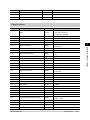
Contents
1. Before Operation …………………………………………………………………………………………7
Operation Flow ………………………………………………………………………………………………8
Layouts of Screens/Windows ………………………………………………………………………………9
Layout of Main Screen (ADJUST Window) ……………………………………………………………9
Layout of Main Screen (RUN Window)…………………………………………………………………12
Layout of Edit Flow Window ……………………………………………………………………………15
Layout of Property Setting Window ……………………………………………………………………17
Checking System Configuration …………………………………………………………………………18
Basic Configuration of FZ3 Series………………………………………………………………………18
Preparing Controllers and Cameras ………………………………………………………………………19
Preparing Controllers ……………………………………………………………………………………19
Adjusting Cameras ………………………………………………………………………………………19
Intelligent Camera (with Lighting Function) ……………………………………………………………20
Input Operations ……………………………………………………………………………………………21
Operation of Touch Pen …………………………………………………………………………………21
Basic Operation of Mouse and Trackball ………………………………………………………………21
Returning Controller to Factory Settings …………………………………………………………………23
Initializing Controller [System Initialization] ……………………………………………………………23
Restarting Controller [System Restart]…………………………………………………………………23
Saving Settings and Turning Power Off …………………………………………………………………24
Turning Off LCD …………………………………………………………………………………………24
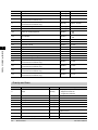
2. Setting Scenes (Measurement Flow)
…………………………………………………………27
What Is a Scene?……………………………………………………………………………………………28
Scene Examples …………………………………………………………………………………………28
What Is a Scene Group?……………………………………………………………………………………32
Creating a Scene ……………………………………………………………………………………………33
Processing Item Selection Guidelines ……………………………………………………………………35
Selecting Measurement Processing Items Using a Chart ……………………………………………35
Selecting Measurement Processing Items According to the Measurement Method and Purpose
……………………………………………………………………………………………………………………42
Editing Processing Units in Scenes ………………………………………………………………………48
Switching Scenes and Scene Groups ……………………………………………………………………50
Switching Scenes ………………………………………………………………………………………50
Switching Scene Groups ………………………………………………………………………………50
Editing Scenes ………………………………………………………………………………………………52
Copying a Scene …………………………………………………………………………………………52
Clearing a Scene …………………………………………………………………………………………52
Renaming a Scene and Adding a Description…………………………………………………………53
Editing Scene Groups ………………………………………………………………………………………55
Copying a Scene Group …………………………………………………………………………………55
Deleting a Scene Group …………………………………………………………………………………56
Renaming a Scene Group ………………………………………………………………………………56
3. Performing Test Measurement/Starting Operation………………………………………59
ADJUST Window and RUN Window………………………………………………………………………60
FZ3 User's Manual
1
ADJUST Window …………………………………………………………………………………………60
RUN Window ……………………………………………………………………………………………60
Switching to the RUN Window …………………………………………………………………………62
Switching to the ADJUST Window ……………………………………………………………………62
Performing Test Measurement ……………………………………………………………………………63
Key Points for Adjustment …………………………………………………………………………………65
Stabilizing Measurement ………………………………………………………………………………65
Shortening Processing Time ……………………………………………………………………………67
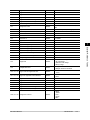
Arranging the RUN Window ………………………………………………………………………………68
Displaying Multiple Windows Together ………………………………………………………………68
Changing Display Contents ……………………………………………………………………………69
Enlarging Measurement Images [Zoom Images] ……………………………………………………73
Displaying Flow and Detailed Results …………………………………………………………………73
Switching the RUN Window to Fast View Mode [Select RUN Mode] ………………………………74
Changing Display Contents on the RUN Window Measurement Information Display Area ……75
Changing Functions That Can Be Operated from the RUN Window Tool Box ……………………75
Useful Functions for Operation ……………………………………………………………………………76
Remeasuring Saved Images ……………………………………………………………………………76
Improving Adjustment Efficiency ………………………………………………………………………77
Changing Judgement Conditions without Stopping Measurement …………………………………79
Changing Regions as a Batch [Shift area] ……………………………………………………………81
Monitoring Measurement Value Trends ………………………………………………………………82
Logging Measurement Values and Measurement Images …………………………………………82
Analyzing Logging Data …………………………………………………………………………………88
Clearing Measurement Results …………………………………………………………………………90
Clearing Saved Images …………………………………………………………………………………90
Capturing Screens ………………………………………………………………………………………91
4. Saving/Loading Data …………………………………………………………………………………93
Basic Knowledge about Data Saving ……………………………………………………………………94
About Saving Areas………………………………………………………………………………………94
About USB Drive Names ………………………………………………………………………………94
Saving Settings Data to Controller Memory………………………………………………………………96
When Using Scene Group 0 ……………………………………………………………………………96
When Using Scene Groups 1 to 31 ……………………………………………………………………96
Saving Settings Data to RAMDisk/USB Device …………………………………………………………98
Saving Logging Images to RAMDisk/USB Device ……………………………………………………100
Copying/Moving Files ……………………………………………………………………………………101
Loading Settings Data to Controller ……………………………………………………………………103
5. Changing the System Environment
…………………………………………………………105
Setting Conditions for Camera Use ……………………………………………………………………106
Checking Camera Connections [Camera Connection] ……………………………………………106
Setting Trigger Delay [Inter-camera Setting]…………………………………………………………106
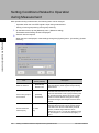
Setting Conditions Related to Operation during Measurement ………………………………………108
Setting the System Operation Environment ……………………………………………………………110
Setting the Date and Time [Date-time Setting] ………………………………………………………110
Selecting the Language [Language Setting] …………………………………………………………110
Setting the Fan Rotation Speed [Fan Control Setting]………………………………………………111
2
FZ3 User's Manual
Setting the Start-up Status [Startup Setting] …………………………………………………………112
Setting the RUN Window Display [RUN mode View Setting] ………………………………………114
Setting the RUN Window Shortcut [Create Shortcut] ………………………………………………115
Setting the Encoder Trigger [Encoder Trigger Setting] ……………………………………………115
Setting the STEP Input Detection Pulse Width [STEP Setting] ……………………………………116
Setting the RUN Window Password [Password Setting]……………………………………………117
Checking System Information [System Information] ………………………………………………119
6. Methods for Connecting and Communicating with External Devices
…………121
About Connecting with External Devices ………………………………………………………………122
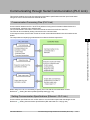
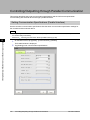
Communicating through Serial Communication (PLC Link) …………………………………………123
Communication Processing Flow (PLC Link) ………………………………………………………123
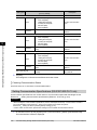
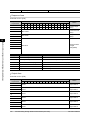
Setting Communication Specifications (Ethernet - PLC Link) ……………………………………123
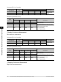
Setting Communication Specifications (RS-232C/422-PLC Link) …………………………………126
Memory Allocation (PLC Link) …………………………………………………………………………129
Command Control (PLC Link) …………………………………………………………………………131
Data Output (PLC Link) ………………………………………………………………………………140
Timing Chart (PLC Link) ………………………………………………………………………………140
Ladder Program Example (PLC Link)…………………………………………………………………144
Controlling/Outputting through Serial Communication (Non-procedure) ……………………………145
Communication Processing Flow (Non-procedure) …………………………………………………145
Setting Communication Specifications (Ethernet - Non-procedure) ………………………………145
Setting Communication Specifications (RS-232C/422 - Non-procedure)…………………………147
Checking Communication Status (Non-procedure) …………………………………………………149
Command Format (Non-procedure) …………………………………………………………………150
Command List (Non-procedure) ………………………………………………………………………151
Output Format (Non-procedure) ………………………………………………………………………176
Controlling/Outputting through Parallel Communication ………………………………………………178
Setting Communication Specifications (Parallel Interface) …………………………………………178
Checking Communication Status (Parallel Interface) ………………………………………………180
I/O Format (Parallel Interface) …………………………………………………………………………181
Timing Chart ……………………………………………………………………………………………183
Externally Outputting Data through FTP ………………………………………………………………192
Setting Communication Specifications ………………………………………………………………192
Communication Example ………………………………………………………………………………193
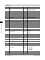
7. External Reference Tables
………………………………………………………………………195
Input image …………………………………………………………………………………………………198
Measurement Image Switching ………………………………………………………………………198
Measurement ………………………………………………………………………………………………199
Search ……………………………………………………………………………………………………199
Flexible Search …………………………………………………………………………………………200
Sensitive Search ………………………………………………………………………………………201
ECM Search ……………………………………………………………………………………………203
EC Circle Search ………………………………………………………………………………………204
Shape Search+ …………………………………………………………………………………………206
Classification ……………………………………………………………………………………………208
Edge Position ……………………………………………………………………………………………209
Edge Pitch ………………………………………………………………………………………………210
FZ3 User's Manual
3
Scan Edge Position ……………………………………………………………………………………211
Scan Edge Width ………………………………………………………………………………………212
Color Data ………………………………………………………………………………………………213
Gravity and Area ………………………………………………………………………………………214
Labeling …………………………………………………………………………………………………216
Label Data ………………………………………………………………………………………………217
Labeling+ ………………………………………………………………………………………………218
Defect ……………………………………………………………………………………………………222
Precise Defect …………………………………………………………………………………………222
Fine Matching……………………………………………………………………………………………223
Character Inspection……………………………………………………………………………………224
Date Verification ………………………………………………………………………………………225
Model Dictionary ………………………………………………………………………………………226
Barcode+…………………………………………………………………………………………………227
2D Code+ ………………………………………………………………………………………………228
Circle Angle ……………………………………………………………………………………………230
Compensate image ………………………………………………………………………………………231
Position Compensation…………………………………………………………………………………231
Trapezoidal Correction+ ………………………………………………………………………………231
Filtering …………………………………………………………………………………………………232
Background Suppression ………………………………………………………………………………232
Color Gray Filter…………………………………………………………………………………………233
Extract Color Filter………………………………………………………………………………………234
Anti Color Shading………………………………………………………………………………………235
Stripes Removal Filter+ ………………………………………………………………………………235
Halation Cut+ ……………………………………………………………………………………………236
Panorama+ ………………………………………………………………………………………………236
Polar Transformation …………………………………………………………………………………237
Support measurement ……………………………………………………………………………………238
Calculation ………………………………………………………………………………………………238
Line Regression …………………………………………………………………………………………238
Circle Regression ………………………………………………………………………………………239
Calibration+ ……………………………………………………………………………………………239
Set Unit Data ……………………………………………………………………………………………240
Get Unit Data ……………………………………………………………………………………………240
Set Unit Figure …………………………………………………………………………………………240
Get Unit Figure …………………………………………………………………………………………240
Trend Monitor ……………………………………………………………………………………………241
Image Logging …………………………………………………………………………………………242
Data Logging ……………………………………………………………………………………………242
Elapsed Time ……………………………………………………………………………………………243
Wait ………………………………………………………………………………………………………243
Branch ………………………………………………………………………………………………………244
Conditional Branch ……………………………………………………………………………………244
DI Branch ………………………………………………………………………………………………244
Output result ………………………………………………………………………………………………245
Data Output ……………………………………………………………………………………………245
Parallel Data Output ……………………………………………………………………………………245
Parallel Judgement Output ……………………………………………………………………………246
4
FZ3 User's Manual
Display result ………………………………………………………………………………………………247
Result Display …………………………………………………………………………………………247
Display Image File ………………………………………………………………………………………247
Display Last NG Image …………………………………………………………………………………247
8. Appendixes ………………………………………………………………………………………………249
About Lenses ………………………………………………………………………………………………250
Error Messages and Troubleshooting …………………………………………………………………256
FAQ …………………………………………………………………………………………………………259
During Start-up …………………………………………………………………………………………259
During Operation ………………………………………………………………………………………259
For Measurement ………………………………………………………………………………………260
About Parallel Interface ………………………………………………………………………………260
About Serial Interface (RS-232C/422 Connection) …………………………………………………261
Measurement Mechanism ………………………………………………………………………………262
Color Processing Mechanism …………………………………………………………………………262
Search Processing Mechanism ………………………………………………………………………262
Edge Detection Measurement …………………………………………………………………………266
Defect Detection Measurement ………………………………………………………………………268
Handling Coordinates …………………………………………………………………………………269
Terminology Explanations ………………………………………………………………………………271
Basic Knowledge about Operations ……………………………………………………………………275
Inputting Values …………………………………………………………………………………………275
Inputting Text ……………………………………………………………………………………………275
Selecting Files and Folders ……………………………………………………………………………276
Available Operations in Select File Window …………………………………………………………278
Using the Zoom Function ………………………………………………………………………………279
Setting Figures ……………………………………………………………………………………………281
Layout of Figure Setting Area …………………………………………………………………………281
Setting Methods…………………………………………………………………………………………282
About OR Setting/NOT Setting ………………………………………………………………………290
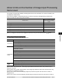
About Number of Logging Images ………………………………………………………………………292
About Limits on the Number of Image Input Processing Items Used ………………………………293
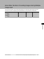
About Max. Number of Loading Images during Multiple Image Input ………………………………295
Character Code Table ……………………………………………………………………………………296
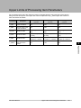
Upper Limits of Processing Item Parameters …………………………………………………………297
About Memories Usable with FZ Series…………………………………………………………………298
Index ……………………………………………………………………………………………………………299
FZ3 User's Manual
5
How This Manual Is Organized
This manual includes two manuals: the "User's Manual", which describes basic operations and settings
for vision sensors, and the "Processing Item List Manual", which describes the setting options for each
processing item.
Conventions Used in This Manual
Symbols
The symbols used in this manual have the following meanings.
Indicates relevant operational precautions that must be followed.
Indicates operation-related suggestions from OMRON.
Use of Quotation Marks and Brackets
In this manual, menus and other items are indicated as follows.
[]
Menu
Indicates the menu names or processing items shown in the menu bar.
""
Item name
Indicates the item names displayed on the screen.
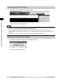
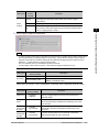
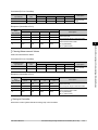
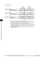
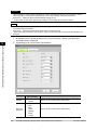
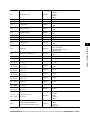
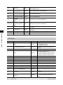
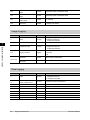
Version Upgrade Information
The newly added functions are described here
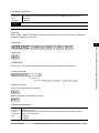
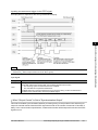
Revision history from Version 2.0 to 2.1
Added Function
6
Note on Newly-Added Function
Reference in Manual
Shape Search+
Handling size change
Measurement is now possible even when the size of
measurement objects change.
Reference:
"Processing
Item List Manual", " Shape
Search+" (p.94)
2D Code+
Support code colors
Measurement is now possible for white 2D codes on
black backgrounds.
Reference: "Processing Item
List Manual", " 2D Code+" (p.265)
FZ3 User's Manual
1
Before Operation
Before Operation
This chapter describes the basic flow and preparations
before beginning operation.
Reference: Operation Flow (p.8)
Reference: Layouts of Screens/Windows (p.9)
Reference: Checking System Configuration (p.18)
Reference: Preparing Controllers and Cameras (p.19)
Reference: Input Operations (p.21)
Reference: Returning Controller to Factory Settings (p.23)
Reference: Saving Settings and Turning Power Off (p.24)
FZ3 User's Manual
7
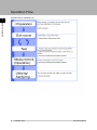
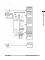
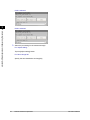
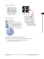
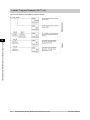
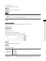
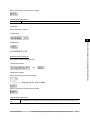
Operation Flow
Operation flow is explained here.
1
Before Operation
8
Operation Flow
FZ3 User's Manual
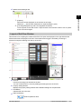
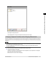
Layouts of Screens/Windows
Screens vary with the status of the operation being performed. The structure of some typical screens
and the functions for the various buttons are described here.
1
Before Operation
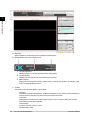
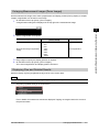
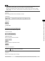
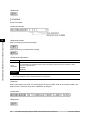
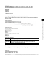
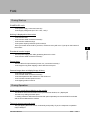
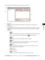
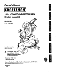
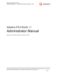
Layout of Main Screen (ADJUST Window)
This screen is used to check whether measurement is being performed correctly according to the set
conditions.
FZ3 User's Manual
Layouts of Screens/Windows
9
1
Before Operation
a.
b.
Menu Bar
Select operations and settings menus related to measurement.
Measurement Information Display Area
1.
2.
3.
c.
Toolbar
Commonly-used functions appear in the toolbar.
●
●
●
●
10
Overall judgement
Displays a scene's overall judgement result ( [OK]/ [NG]).
Processing time
Displays the time required for the measurement process.
Status display
Displays the scene group number, scene number, external output status, and image mode
for the currently displayed scene.
Edit flow
The Edit Flow window is displayed. Addition and deletion of processing units and switching
of the processing sequence is performed in the Edit Flow window.
Data save
Setting data is saved into the internal flash memory in the controller. Make sure to save
when settings have been modified.
Scene switch
To switch a scene group or scene.
Measure/Stop meas.
Layouts of Screens/Windows
FZ3 User's Manual
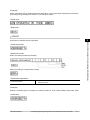
●
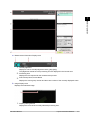
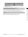
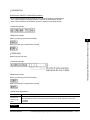
d.
Starts/stops measurement.
Switch to RUN mode
Switches to the RUN window.
Image Display Area
Displays the measured image.
1
Before Operation
1.
e.
Property setting buttons
Displays the name of the currently selected processing item.Moving to the property setting
window can be done by tapping here.
Control Area
Displays "Test measurement", "Flow", "Detail result", and "Image display".
●
●
Test measurement
Use when test measurement conditions and images that have been acquired are used for
remeasurement.
Flow
Displays the judgement results for the flow and each unit.
1. Moves to the top processing unit with an NG error.
●
2. Moves to the next processing unit with an NG error.
Detail result
The detailed measurement results of the processing units selected in the measurement
flow are displayed as text.
FZ3 User's Manual
Layouts of Screens/Windows
11
1
●
Before Operation
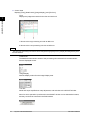
f.
Image display
Sets the display method for the Image Display area.
Measurement Manager Bar
1.
2.
[Capture]
Saves the content displayed on the monitor as an image.
Reference:
Set the save destination for captured images. (p.92)
[LCD Off] (Displayed only with LCD-integrated controllers.)
Turns off power to the LCD monitor. Tap the bottom of the monitor screen to turn on power
to the LCD monitor again.
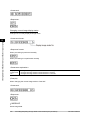
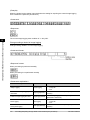
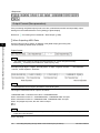
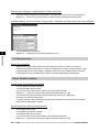
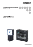
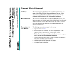
Layout of Main Screen (RUN Window)
This window is used during operation.
12
Layouts of Screens/Windows
FZ3 User's Manual
1
Before Operation
a.
Measurement Information Display Area
1.
2.
3.
b.
Overall judgement
Displays a scene's overall judgement result ( [OK]/ [NG]).
The judgement results for each processing unit are displayed in the Control area.
Processing time
Displays the time required for the measurement process.
Scene Group Name, Scene Name
Displays the scene group number and the scene number of the currently displayed scene.
Image Display Area
Displays the measured image.
1.
Property setting buttons
Displays the name of the currently selected processing item.
FZ3 User's Manual
Layouts of Screens/Windows
13
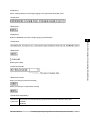
c.
Control Area
Displays [Flow], [Detail result], [Image display], and [Tool box].
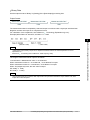
●
1
Flow
Displays the judgement results for the flow and each unit.
Before Operation
1. Moves to the top processing unit with an NG error.
2. Moves to the next processing unit with an NG error.
Note
●
The size of the processing unit buttons can be changed through [View] menu - [Display the enlarged flow] in the
ADJUST Window.
●
●
●
Detail result
The detailed measurement results of the processing units selected in the measurement
flow are displayed as text.
Image display
Sets the display method for the Image Display area.
Tool box
Starts and stops simplified non-stop adjustment, and switches to the ADJUST window.
Items for which operation is performed in the ADJUST window can be allocated to buttons,
and they can then be executed in the RUN window.
14
Layouts of Screens/Windows
FZ3 User's Manual
d.
Measurement Manager Bar
1
2.
[Capture]
Saves the content displayed on the monitor as an image.
Reference:
Set the save destination for captured images. (p.92)
[LCD Off] (Displayed only with LCD-integrated controllers.)
Turns off power to the LCD monitor. Tap the bottom of the monitor screen to turn on power
to the LCD monitor again.
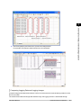
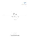
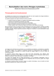
Layout of Edit Flow Window
This window is for compiling the measurement flow.Flow parts are displayed on the right side and the
measurement flow is displayed on the left. If the measurement trigger is activated, processing is
executed in sequence starting from the top of the flow.
a.
b.
c.
d.
Unit List
Lists the processing units included in the flow.
You can create a flow for a scene by adding processing items to the unit list.
Property Setting Buttons
Displays the property setting window where detailed settings can be performed.
End Marker
Indicates the end of the flow.
Edit Flow Buttons
●
FZ3 User's Manual
Search up/Search down
Layouts of Screens/Windows
15
Before Operation
1.
Searching can be performed to find out what position a processing item occupies in the
unit list.
The icon for the processing item to be searched for is selected in the processing item tree
and clicked.
1
Before Operation
This function is convenient when setting long flows.
Select top/Select bottom
●
Selects the processing unit at the top or bottom of the flow.
Select above/Select below
●
●
●
●
●
●
●
●
●
●
●
●
e.
Display Options
●
●
●
●
f.
16
Selects the processing unit located one above or one below the currently selected
processing unit.
Rename
Displays a window for renaming the selected processing unit.
Move up/Move down
Moves the selected processing unit upward or downward.
Copy
Copies the selected processing unit.
Paste
Pastes the copied processing unit immediately before the selected processing unit.Pasting
cannot be performed if any operations other than paste are performed after copying.
Delete
Deletes the selected processing unit.
Append (Bottom)
Adds a processing unit to the bottom of the flow.
Insert
Inserts a new processing unit immediately before the selected processing unit.
New folder
Used when multiple processing units are managed as one group.
Shift area
Changes related figure data in one batch.
Multiple selection
Used when processing units are copied or deleted together.
Set
Displays the processing item setting window for the selected processing unit.
Show guide
When checked, explanations for processing items are displayed.
Enlarge flow
When checked, the "a Unit list" flow is displayed with large icons.
Enlarge item tree
When checked, the "f Processing item tree" is displayed with large icons.
Ref. other Scene's flow
When checked, other scene flows within the same scene group can be referred to.
Processing Item Tree
This area is for selecting processing items to add to the flow.Processing items are classified by
type and displayed as a tree. Tapping the plus sign "+" of any item displays expanded contents
Layouts of Screens/Windows
FZ3 User's Manual
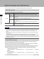
g.
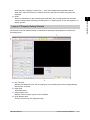
Layout of Property Setting Window
This window is used for detailed setting of measurement parameters and judgement conditions for
processing items.
a.
b.
c.
d.
Item Tab Area
Displays the settings items for the processing unit currently being set.Perform settings starting
with the item on the left.
Detail Area
Set detailed items.
Image Display Area
Displays camera images, figures, and coordinates.
Zoom Browser Area
Zooms in and out from the displayed image.
FZ3 User's Manual
Layouts of Screens/Windows
17
1
Before Operation
below that item. Tapping the minus sign "-" of any item collapses the expanded contents.
When "Ref. other Scene's flow" is checked, the scene select box and other scene flows are
displayed.
Guide
Shows an explanation for the processing item selected in the processing item tree.These are
used as reference when selecting processing items. To display guides, check "Show guide" in "e
Display options".
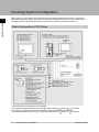
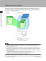
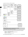
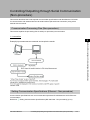
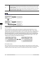
Checking System Configuration
1
This product is a vision sensor for performing image processing measurement through a controller of
objects photographed using a camera.By connecting an external device such as a PC, measurement
commands can be input and measurement results can be output from the external device.
Before Operation
Basic Configuration of FZ3 Series
*1: The touch pen is an accessory of a controller.
*2: FZ-SC2M and FZ-S2M cannot be connected with the FZ3-3
/FZ3-H3
controllers.
*3: Lenses for small-size cameras are required for small-size 300,000-pixel cameras.
*4: FZ-SC5M and FZ-S5M can only be connected with the FZ3-70
/FZ3-H70
controllers.
18
Checking System Configuration
FZ3 User's Manual
Preparing Controllers and Cameras
1
No special preparation is required with this product as processing items are pre-installed.Please check
that the controller is switched on and that the Main screen is displayed.
For details, see the User's Manual.
The first time the program is started up, the Language Setting window is displayed, so select the
language.
Reference:
Selecting the Language [Language Setting] (p.110)
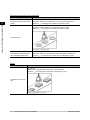
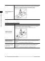
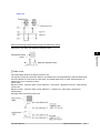
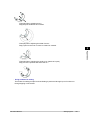
Adjusting Cameras
Confirm what kind of images are being taken.
Adjust the position of measurement objects and the focus of the lens.
1.
Tap [
] of "Image mode" in [Image display] of the Main screen Control area, and select
"Through".
The through images captured from the camera are viewed in the Image Display area.
Reference:
Changing Display Contents (p.69)
Note
●
The same operation is available by tapping [View] - [Image mode] - [Through].
2.
Adjust the position of measurement objects so that they display at the center of the monitor.
3.
Adjust the focal distance of the lens.
When using an auto-focus camera or an intelligent camera, focus and the iris can be
automatically adjusted.
Note
●
●
If a camera is used together with a lens, turn the focus ring of the lens to adjust the focus.
Reference:
"Processing Item List Manual", "Lens Setting" (p.21)
The light intensity of an intelligent camera can be adjusted from the controller.
Reference:
"Processing Item List Manual", "Lighting Control" (p.18)
FZ3 User's Manual
Preparing Controllers and Cameras
19
Before Operation
Preparing Controllers
Important
●
When using a small-size digital camera, check that the model and serial number of the camera head
and camera amplifier match.When a camera head and camera amplifier of different models and serial
numbers are connected, they may not operate correctly.
1
Before Operation
Intelligent Camera (with Lighting Function)
Proper lighting is of crucial importance to vision sensors.
If an intelligent camera is connected, lighting can be controlled from the controller.
Features of intelligent cameras are as follows:
●
●
●
●
A single camera enables testing of illumination from various angles, so it is possible to shorten
the lighting setting time and test measurement time.
The controller controls lighting, so lighting can be adjusted depending upon the product type.
Reproducibility of lighting settings is improved.
Settings can be modified without changing lighting.
Reference:
20
"Processing Items List Manual", "Screen Adjust Settings (Camera Image Input)" (p.18)
Preparing Controllers and Cameras
FZ3 User's Manual
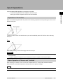
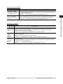
Input Operations
Input operations differ depending on the type of controller.
●
●
1
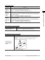
Operation of Touch Pen
With a Controller integrated with LCD, perform the following operations when operating the touch screen
with the touch pen.
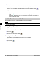
Tapping
Lightly touch the screen once with the touch pen and immediately take it off. Perform when selecting
items, etc.
Drag
Draw while pressing on the screen lightly with the touch pen.
Important
●
●
Be sure to use the supplied touch pen for touch screen operations.Using a pencil or ballpoint pen may damage
the touch screen.
In addition, response to operations may be delayed if the screen is tapped continuously and rapidly.
Basic Operation of Mouse and Trackball
With a BOX-type controller, use a mouse with a USB interface or commercially-available trackball.
(See the list for recommended products. Please refer to the product catalog.)
Note
●
Do not use the right mouse button, scroll wheel, or other buttons.
FZ3 User's Manual
Input Operations
21
Before Operation
Controller integrated with LCD: Operation with touch pen
BOX-type controller: Operation with mouse and trackball
Click
1
Before Operation
Press the left mouse button once. Perform when selecting items, etc.
Note
●
This document primarily describes operations using the term "tapping". When using a mouse or trackball, read
"Tapping" to mean "Clicking".
Drag
Move the mouse with the left mouse button held down.
22
Input Operations
FZ3 User's Manual
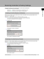
Returning Controller to Factory Settings
All controller settings can be restored to factory default status (initialization).
In addition, the controller can be restarted.
●
1
Initializing Controller [System Initialization] (p.23)
Restarting Controller [System Restart] (p.23)
Before Operation
●
Reference:
Reference:
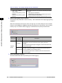
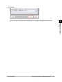
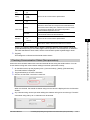
Initializing Controller [System Initialization]
Restores the controller to factory default status. Before initialization, back up required data such as
scene data and system data.
Reference:
Saving Settings Data to RAMDisk/USB Device (p.98)
1.
2.
On the Main screen, tap [System] - [Controller] - [System initialization].
The System Initialization window is displayed.
Tap [Execute].
3.
A confirmation window is displayed.
Tap [Yes].
The controller is initialized and restarts.
Restarting Controller [System Restart]
Restart the controller. Before restarting, back up required data such as scene data and system data.
Reference:
Saving Settings Data to Controller Memory (p.96)
1.
2.
On the Main screen, tap [System] - [Controller] - [System restart].
The System Restart window is displayed.
Tap [OK].
The controller restarts.
FZ3 User's Manual
Returning Controller to Factory Settings
23
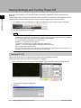
Saving Settings and Turning Power Off
1
Before Operation
Before turning off power to the controller, perform the following operations to save the data that you
have set.
The controller loads scene data from the flash memory each time it is started up. Therefore, the power is
turned off without saving data to the flash memory and any changes made will not be saved.
1.
On the Main screen (the ADJUST window), tap [Data save] in the toolbar to save the set data.
2.
Exit after powering off the controller.
Note
●
●
Data to be saved
Scene data and system data are saved in the controller.Logging images and data saved in the RAMDisk
are not saved. Perform any of the following procedures to keep this data.
- Copy data saved in the RAMDisk to the USB memory.
Reference:
Copying/Moving Files (p.101)
- Change the save destination for logging data to the USB memory.
Reference:
Saving Logging Images to RAMDisk/USB Device (p.100)
When using the scene group function
The scene data set in scene group 0 is saved in the controller.The scene data from scene groups 1 to 31
is saved to the USB memory and overwrites previous saved data.
Turning Off LCD
This function is specific to FZ3-300/700 series LCD monitor integrated controllers.
Turn off the LCD monitor only without turning off the controller.
24
1.
Open the measurement manager bar at the bottom right of the Main screen and tap [LCD Off].
2.
A confirmation message is displayed.
Tap [OK].
Saving Settings and Turning Power Off
FZ3 User's Manual
Power to the LCD monitor is turned off.
Turning LCD On Again
1
FZ3 User's Manual
Saving Settings and Turning Power Off
Before Operation
This function is specific to FZ3-300/700 series LCD monitor integrated controllers.
Tap the lower part of the monitor screen.
The LCD will then be switched on.
25
1
Before Operation
26
Saving Settings and Turning Power Off
FZ3 User's Manual
2
Setting Scenes (Measurement Flow)
Setting Scenes (Measurement Flow)
A measurement flow consisting of a series of combined
processing items is called a scene.This chapter explains
how to create and edit scenes.
Reference: What Is a Scene? (p.28)
Reference: What Is a Scene Group? (p.32)
Reference: Creating a Scene (p.33)
Reference: Processing Item Selection Guidelines (p.35)
Reference: Editing Processing Units in Scenes (p.48)
Reference: Switching Scenes and Scene Groups (p.50)
Reference: Editing Scenes (p.52)
Reference: Editing Scene Groups (p.55)
FZ3 User's Manual
27
What Is a Scene?
2
Processing items for use with various measurement objects and measurement objectives are provided
in this product. By combining and executing these processing items, measurement adapted to the
purpose can be implemented. A combination of processing items is called a "scene" and scenes can be
easily created by combining processing items that are suited to the measurement purpose from the list
of processing items provided.
Setting Scenes (Measurement Flow)
Changing the set-up using the scene function
Multiple scenes can be created.For example, by creating scenes for each measurement object such as
using "Scene 0" to inspect an "ABC" label and "Scene 1" to inspect an "XYZ" label, changing the set-up
can be performed smoothly just by changing the scene even when the measurement object and
measurement objective have changed.
Reference:
Switching Scenes and Scene Groups (p.50)
Up to 32 scenes can be set. In case where over 32 scenes are required, these can be divided into scene
groups for easier management.
Reference:
What Is a Scene Group? (p.32)
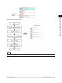
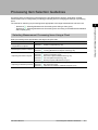
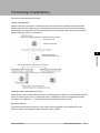
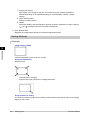
Scene Examples
The processing items registered to the scene are called processing units. In the Edit Flow window where
scenes are created, select processing items required for measurement and add them to the flow. The
number at the top of the processing unit is called the "Unit No.". If the measurement trigger is activated,
processing is executed in the numerical sequence of the processing unit numbers.
28
What Is a Scene?
FZ3 User's Manual
2
Setting Scenes (Measurement Flow)
Example) Normal measurement
Note
●
The processing item "Camera Image Input" is set in processing unit 0 beforehand.
FZ3 User's Manual
What Is a Scene?
29
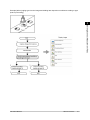
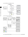
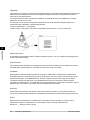
Example) When adding Position Compensation for two measurement objects in the same field of view
2
Setting Scenes (Measurement Flow)
30
What Is a Scene?
FZ3 User's Manual
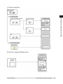
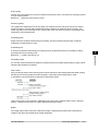
Example) When judging type from the image and dividing later inspection conditions according to type
(branch processing)
2
Setting Scenes (Measurement Flow)
FZ3 User's Manual
What Is a Scene?
31
What Is a Scene Group?
2
A "scene group" refers to a grouping of 32 individual scenes.Creating a scene group is convenient when
increasing the number of scenes and when managing a number of scenes according to category.
USB memory is required for creating a scene group.Scene group 0 is saved in the controller while scene
groups 1 to 31 are saved in USB memory.
Setting Scenes (Measurement Flow)
Note
●
●
●
●
32
The maximum number of scenes that can be used is 1024.32 scenes are handled as 1 scene group, and up to
32 scene groups can be set. In other words, 32 scenes x 32 scene groups = 1024 scenes, which is the
maximum number that can be used.
There are multiple USB ports on the controller, but it is necessary to assign the drive name "USBDisk" to the
USB memory in which the data for the scene group being used is stored.When other USB memory devices are
already inserted, perform this operation after removing all USB memory devices other than the one in which the
scene group data is stored.
If the USB memory capacity is insufficient for the data size, the number of scenes it is possible to set can be set
lower than 1024.The scene data size varies depending on the contents of settings.
The data size that can be set (data memory capacity) can be checked in the system menu.
Reference:
Checking System Information [System Information] (p.119)
What Is a Scene Group?
FZ3 User's Manual
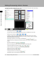
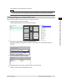
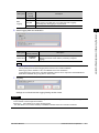
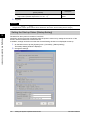
Creating a Scene
This section explains methods for adding a new processing unit to a scene.
1.
3.
The Edit Flow window is displayed.
Select a processing item to be added from the processing item tree.
4.
Tap [Append].
2
Setting Scenes (Measurement Flow)
2.
Display the scene to edit on the Main screen.
Reference:
Switching Scenes and Scene Groups (p.50)
Tap [Edit flow] in Toolbar.
The selected processing item is appended at the bottom of the unit list (flow).
FZ3 User's Manual
Creating a Scene
33
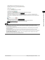
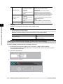
5.
Continue to add processing units.Repeat the steps after Reference:
3 (p.33) .
Note
●
2
6.
Limitations on settings
The number of image input processing items that can be used is limited.
Reference:
About Limits on the Number of Image Input Processing Items Used (p.293)
Either tap the icon of the processing unit to be set or tap the Set button.
Setting Scenes (Measurement Flow)
7.
34
The property setting window is displayed.Set detailed conditions. The displayed contents vary
depending on the processing item.
Set conditions.
The displayed contents vary depending on the processing item.
Creating a Scene
FZ3 User's Manual
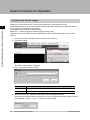
Processing Item Selection Guidelines
Processing items for performing measurement are provided with this product. Application-oriented
measurement can be configured by combining processing items or changing the settings of processing
items.
The method for searching for processing items appropriate to the target measurement is shown here.
●
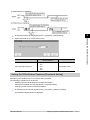
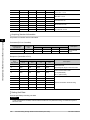
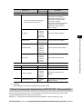
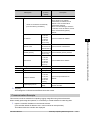
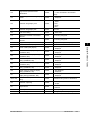
Selecting Measurement Processing Items Using a Chart
Select processing items appropriate to the target using the chart.
Item
References
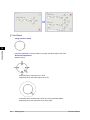
Performing position
compensation for objects
Reference:
Position Compensation (p.36)
Measuring the position of objects
Reference:
Reference:
Locating (Measurement Objects Not Inclined) (p.37)
Locating (Measurement Objects Inclined) (p.38)
Inspecting the status of objects
Reference:
Reference:
Reference:
Reference:
Reference:
Internal and External Inspection (p.38)
Presence Inspection (p.39)
Dimension Inspection/Measurement (p.39)
Text Comparison/Inspection (p.40)
Quantity Inspection/Measurement (p.41)
Reference:
Inspecting for defective products Reference:
Reference:
FZ3 User's Manual
Defect/Contamination Inspection (p.41)
Burr Inspection (p.40)
Inspection for Presence of Different Objects (p.42)
Processing Item Selection Guidelines
35
2
Setting Scenes (Measurement Flow)
●
Reference:
Selecting Measurement Processing Items Using a Chart (p.35)
Reference:
Selecting Measurement Processing Items According to the Measurement Method
and Purpose (p.42)
Position Compensation
2
Setting Scenes (Measurement Flow)
36
Processing Item Selection Guidelines
FZ3 User's Manual
Locating (Measurement Objects Not Inclined)
2
Setting Scenes (Measurement Flow)
FZ3 User's Manual
Processing Item Selection Guidelines
37
Locating (Measurement Objects Inclined)
2
Setting Scenes (Measurement Flow)
Internal and External Inspection
38
Processing Item Selection Guidelines
FZ3 User's Manual
Presence Inspection
2
Setting Scenes (Measurement Flow)
Dimension Inspection/Measurement
FZ3 User's Manual
Processing Item Selection Guidelines
39
Burr Inspection
2
Setting Scenes (Measurement Flow)
Text Comparison/Inspection
40
Processing Item Selection Guidelines
FZ3 User's Manual
Defect/Contamination Inspection
2
Setting Scenes (Measurement Flow)
Quantity Inspection/Measurement
FZ3 User's Manual
Processing Item Selection Guidelines
41
Inspection for Presence of Different Objects
2
Setting Scenes (Measurement Flow)
Hole Position Measurement
Selecting Measurement Processing Items According
to the Measurement Method and Purpose
This section describes methods for selecting processing items appropriate to different measurement
objectives such as counting quantities, checking for deformation, and checking for contamination.
●
●
●
●
42
Reference:
Reference:
Reference:
Reference:
Measuring Positions (p.43)
Detecting Defects and Foreign Materials (p.44)
Count (p.44)
Measuring Dimensions (p.45)
Processing Item Selection Guidelines
FZ3 User's Manual
●
●
●
●
●
Reference:
Reference:
Reference:
Reference:
Reference:
Measuring Folding of Papers and Sheets (p.45)
Checking the Interior/Exterior and Direction (p.45)
Checking for Mixing of Different Objects (p.46)
Checking for Deformation (p.47)
Inspecting Characters (p.47)
2
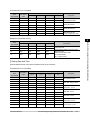
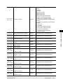
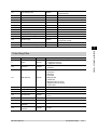
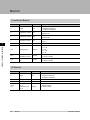
Measuring positions
Positioning of
low-contrast
measurement
objects
References
[ECM Search]
Effective for location positioning of measurement objects, such as LCD substrates, glass
substrates, and sheets, which have low contrast and in which color differences at measurement
locations are not obvious.
Reference:
"Processing Item List Manual", "ECM Search" (p.73)
[Edge Position]
Label position Effective for detecting whether the label position is off-center, raised or lowered, and whether the
detection
label is affixed on bottles and cans.
Reference:
"Processing Item List Manual", "Edge Position" (p.114)
Robot arm
positioning
[Search]
Effective for position measurement that includes tilting of the measurement object due to handling
with robot arms.
Reference:
"Processing Item List Manual", "Search" (p.42)
[Flexible Search]
Effective for position measurement of measurement objects in which there are variations in
markings or shape such as with inspection of packaging, etc.
Reference:
"Processing Item List Manual", "Flexible Search" (p.53)
Position
measurement
for
measurement
objects with
variations
[Search]
If the shape and background of the measurement object are constant, a processing item such as
one that registers an image as a model and searches for this image is effective.
Reference:
"Processing Item List Manual", "Search" (p.42)
Other
positioning
FZ3 User's Manual
Processing Item Selection Guidelines
43
Setting Scenes (Measurement Flow)
Method,
objective
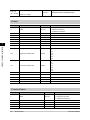
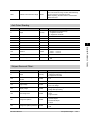
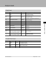
Detecting defects and foreign materials
Method, objective
2
References
Detecting defects, contaminations [Defect]
and spots on plain measurement Effective for detection of contamination or spots on plain backgrounds.
objects
Reference:
"Processing Item List Manual", "Defect" (p.208)
Setting Scenes (Measurement Flow)
[Defect]
Effective for exterior detection of scratches and burrs on parts.
Reference:
"Processing Item List Manual", "Defect" (p.208)
Scratches, burrs
Inspection for minor scratches,
contamination and backgrounds
other than plain backgrounds
[Fine Matching]
Effective for detection of minor defects and contamination on labels, etc.
Reference:
"Processing Item List Manual", "Fine Matching" (p.224)
Count
Method, objective
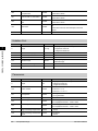
References
[Edge Pitch]
Effective when calculating the number of IC or connector pins.
Reference:
"Processing Item List Manual", "Edge Pitch" (p.124)
Inspection for number of
pins
44
Processing Item Selection Guidelines
FZ3 User's Manual
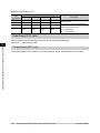
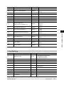
Measuring dimensions
Method,
objective
References
[Edge Position]
Effective when measuring the width of measurement objects.
Reference:
"Processing Item List Manual", "Edge Position" (p.114)
Dimension
inspection of
finished
products
[Edge Position] [Calculation]
To measure the dimensions of finished products, combine [Edge Position] and [Calculation]. Use
[Edge Position] to measure position, and [Calculation] to calculate dimensions by calculating the
distance between positions.
Reference:
"Processing Item List Manual", "Edge Position" (p.114)
Reference:
"Processing Item List Manual", "Calculation" (p.328)
Dimension
inspection for
circular shapes
and
obliquely-shaped
parts
[Edge Position] [Calculation]
[Edge Position] is effective when measuring the dimensions of circular work pieces and tilted
measurement objects. Use this processing item to measure positions, and calculate dimensions
by calculating the spacing between positions with [Calculation].
Reference:
"Processing Item List Manual", "Edge Position" (p.114)
Reference:
"Processing Item List Manual", "Calculation" (p.328)
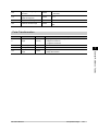
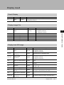
Measuring folding of papers and sheets
Method, objective
Checking for folding on plain
measurement objects
References
[Defect]
Effective when checking for folding on plain work pieces.
Reference:
"Processing Item List Manual", "Defect" (p.208)
Checking the interior/exterior and direction
Method, objective
References
[Flexible Search]
Effective when there is variation in the size and position of the markings to be
checked.
Reference:
"Processing Item List Manual", "Flexible Search" (p.53)
Interior/exterior and
orientation inspection
through presence of
markings
FZ3 User's Manual
Processing Item Selection Guidelines
45
2
Setting Scenes (Measurement Flow)
Measuring
width of
measurement
objects
[Fine Matching]
Effective when there are patterns on the background of markings, markings have a
complex shape, or precision is required for measurement of markings.
Reference:
"Processing Item List Manual", "Fine Matching" (p.224)
2
Setting Scenes (Measurement Flow)
When precision is required
for measurement of
markings
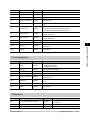
Checking for mixing of different objects
Method, objective
References
[Flexible Search]
Effective for inspection of mixing of different objects in which there are variations
with markings and the shape of measurement objects.
Reference:
"Processing Item List Manual", "Flexible Search" (p.53)
Inspection for mixing of
different measurement
objects with variations
Inspection for mixing of
different objects for objects
with plain background
[Search]
Effective for inspection of mixing of different objects for packaging that has plain
background.
Reference:
"Processing Item List Manual", "Search" (p.42)
When precision is required
for inspection of mixing of
different objects
[Fine Matching]
Effective when precision is required for inspection of mixing of different objects
such as inspection of nameplates and objects other than those with plain
backgrounds.
Reference:
"Processing Item List Manual", "Fine Matching" (p.224)
46
Processing Item Selection Guidelines
FZ3 User's Manual
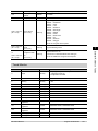
Checking for deformation
Method, objective
References
Deformation checking
when there are multiple
acceptable shapes
[Flexible Search]
Effective when performing inspection for deformation of measurement objects based
on multiple acceptable shapes.
Reference:
"Processing Item List Manual", "Flexible Search" (p.53)
When more precisely
measuring the shape
[Fine Matching]
Effective when inspecting the shape of work pieces to a high degree of precision..
Reference:
"Processing Item List Manual", "Fine Matching" (p.224)
2
Setting Scenes (Measurement Flow)
Inspecting characters
Method,
objective
References
Inspecting the
date
[Date Verification]
Effective when inspecting date character strings that show the production date, etc. The
verification date can be set automatically.
Reference:
"Processing Item List Manual", "Date Verification" (p.242)
Inspecting
arbitrary
character
strings
[Character Inspection]
Effective when inspecting arbitrary character strings.
Reference:
"Processing Item List Manual", "Character Inspection" (p.235)
Registering
character
strings
[Model Dictionary]
To inspect character strings with [Date Verification] or [Character Inspection], register the target
character strings with [Model Dictionary].
Reference:
"Processing Item List Manual", "Model Dictionary" (p.251)
FZ3 User's Manual
Processing Item Selection Guidelines
47
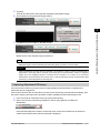
Editing Processing Units in Scenes
In the Edit Flow window, editing buttons in the window can be used to change the order of processing
units within the scene or to delete processing units.
2
Setting Scenes (Measurement Flow)
●
Searching processing units (
)(
)
Convenient when the processing unit you want to select is not displayed on the screen.
●
Selecting a processing unit (
)(
)(
)(
)
In addition to tapping the property setting button icons, the editing buttons can be used to
automatically select the processing unit at the top or bottom, or above or below an arbitrarily
selected processing unit in the unit list.
●
Specifying the position for a processing unit and adding it (
)(
)
Adds and inserts a processing unit at the bottom position of the scene or another specified
position.
●
Moving a processing unit (
)(
)
Moves a processing unit within a scene and changes the processing order.
●
Copying and pasting a processing unit (
)(
)
Copies and pastes a processing unit while maintaining settings data.
●
Deleting a processing unit (
)
Deletes processing units within a scene.
●
Changing the name of a processing unit (
)
Changes the name of a processing units within a scene.
48
Editing Processing Units in Scenes
FZ3 User's Manual
●
Setting details of a processing unit (
)
Sets the properties of any processing unit in a scene.
●
Shift area(
)
Changes related figure data in one batch.
●
●
)
2
Select when multiple processing units are to be managed as one group.
Operating processing units as a group (
)
Used when processing units are copied or deleted together.A checkbox is displayed in the
processing unit if [Multiple selection] is tapped. Checked processing units can be operated as a
group.
Referring to other scene flows (
)
Units of other scenes can be referred to and added to the current scene flow.
Selecting a scene to refer to displays the flow for that scene.
Note
●
●
●
●
If a processing unit is inserted, the numbers for the subsequent processing units increase by one.With
processing items related to results output or branch control, the numbers for processing units set as references
also automatically increase by one.
If a button other than [Paste] is tapped after pasting a processing unit, continued pasting of the processing
cannot be performed.
If a processing unit is deleted, the numbers for the subsequent processing units decrease by one.With
processing items related to results output or branch control, the numbers for processing units set as references
also automatically decrease by one.
To make a specific processing unit not display in a flow on the ADJUST window or RUN window, insert a "*"
(single byte) at the beginning of the processing unit name.
FZ3 User's Manual
Editing Processing Units in Scenes
49
Setting Scenes (Measurement Flow)
●
Creating a folder (
Switching Scenes and Scene Groups
2
Set-up can be changed by changing the scene. With factory settings, the default display is scene 0 when
the power is switched on. In addition, multiple scenes can be created (Scene 1 to 31).
Also, when combined with the scene group function, up to 1024 scenes can be set.
Instructions for switching scene groups and scenes can also be performed from external devices.
Reference:
Methods for Connecting and Communicating with External Devices (p.121)
Setting Scenes (Measurement Flow)
Switching Scenes
1.
Tap "Scene switch" in the toolbar on the Main screen.
The Switch Scene window is displayed.
Note
●
2.
3.
The same operation is available by tapping [Scene] menu - [Scene switch].
Tap [
] to select the scene to switch.
To switch a scene group, tap [Switch], then tap [
group to switch.
Tap [OK].
The scene switches.
] in the displayed window to select the scene
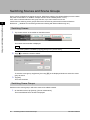
Switching Scene Groups
Switches to the scene group in which the scene to be edited is stored.
1.
50
On the Main screen, tap [Scene] - [Scene maintenance].
The Scene Maintenance window is displayed.
Switching Scenes and Scene Groups
FZ3 User's Manual
2.
Tap [Switch] for the scene group.
2
Setting Scenes (Measurement Flow)
3.
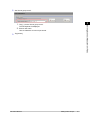
The Switch Scene Group window is displayed.
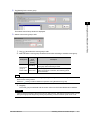
Switch to the scene group to edit.
1.
2.
Tap [
] and select the scene group to edit.
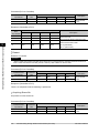
Select whether a scene group should be saved when switching to another scene group.
Setting item
Setting
value
[Factory
default]
[Checked]
Save scene
group on
switch scene Unchecked
Description
When the scene group is switched, the data of the
scene group before switching is saved.
The scene group data is not saved when switching to
another scene group. Therefore, the switching period
can be shortened.
Note
●
The setting for whether to save a scene group during switching is linked to the settings of the
Measurement Setting window.
Reference:
Setting Conditions Related to Operation during Measurement (p.108)
3.
Tap [OK].
The scene group is switched and the screen returns to the Scene Maintenance window.
Important
●
When a check is inserted in "Save scene group on switch scene", data may be lost if the power is cut off
during scene group switching.During scene group switching, make sure that the power is not cut off.
FZ3 User's Manual
Switching Scenes and Scene Groups
51
Editing Scenes
Copying a Scene
2
Setting Scenes (Measurement Flow)
Copies and pastes scenes within a scene group.
This is a convenient function for reusing a created scene with only one portion being changed.
1.
2.
3.
4.
5.
On the Main screen, tap [Scene] - [Scene maintenance].
The Scene Maintenance window is displayed.
In the scene list, tap the source scene to copy, and then tap [Copy].
In the scene list, tap the scene to which the copy is to be pasted and then tap [Paste].
The confirmation window for overwriting is displayed.
Tap [Yes].
The copied scene data is written over the scene selected as the destination.
Tap [Close].
Clearing a Scene
Clear scene settings and return to factory default values. This section describes how to initialize
measurement contents for each scene.
1.
2.
52
On the Main screen, tap [Scene] - [Scene maintenance].
The Scene Maintenance window is displayed.
Tap the scene to be cleared from scene list.
Editing Scenes
FZ3 User's Manual
3.
Tap [Clear].
2
Setting Scenes (Measurement Flow)
4.
A confirmation message is displayed.
Tap [Yes].
5.
Scene data is cleared.
Tap [Close].
Renaming a Scene and Adding a Description
Arbitrary descriptions can be added to each scene.This is convenient for making settings more easily
understandable when managing many scenes.
1.
2.
On the Main screen, tap [Scene] - [Scene maintenance].
The Scene Maintenance window is displayed.
Tap the scene to be renamed from scene list.
FZ3 User's Manual
Editing Scenes
53
3.
Set "Scene name", "Author" and "Note".
2
Setting Scenes (Measurement Flow)
1.
2.
Tap [...] for each item.
The soft keyboard is displayed.
Set the name and a description.
"Scene name" and "Author" cannot be longer than 15 characters, and "Note" cannot be
longer than 255 characters.
゜ and " cannot be used alone as a "Scene name".
Note
●
4.
54
When writing "Note", enter a line-break after 32 single-byte characters or 17 double-byte characters.
Without a line break, the display of character strings is truncated.
Tap [Close].
Editing Scenes
FZ3 User's Manual
Editing Scene Groups
Copying or deleting can be done by scene group and scene groups can be arbitrarily renamed.
Note
●
Make sure to check that a USB memory device has been inserted before performing this operation.
2
Setting Scenes (Measurement Flow)
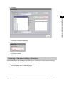
Copying a Scene Group
1.
2.
On the Main screen, tap [Scene] - [Scene maintenance].
The Scene Maintenance window is displayed.
Tap [Edit].
3.
The Scene Group Maintenance window is displayed.
Select the scene group to copy and tap [Copy].
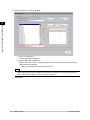
4.
5.
6.
Select the copy destination scene group and tap [Paste].
The confirmation window for overwriting is displayed.
Tap [Yes].
The copied scene group data is written over the scene group selected as the destination.
Tap [Close].
FZ3 User's Manual
Editing Scene Groups
55
Deleting a Scene Group
Delete scene group data. The data to be deleted is shown as follows.
●
●
Names set for a scene group
All scene data within a scene group
2
1.
Setting Scenes (Measurement Flow)
2.
On the Main screen, tap [Scene] - [Scene maintenance].
The Scene Maintenance window is displayed.
Tap [Edit].
3.
The Scene Group Maintenance window is displayed.
Select the scene group to delete and tap [Clear].
4.
5.
A confirmation message is displayed.
Tap [Yes].
Scene group data is deleted.
Tap [Close].
Renaming a Scene Group
Scene groups can be arbitrarily named. This is convenient for managing more than one scene group.
1.
56
On the Main screen, tap [Scene] - [Scene maintenance].
The Scene Maintenance window is displayed.
Editing Scene Groups
FZ3 User's Manual
2.
Set "Scene group name".
1.
3.
Setting Scenes (Measurement Flow)
2.
2
Tap [...] for the "Scene group name".
The soft keyboard is displayed.
Enter a new name.
Use 15 characters or less to Input words.
Tap [Close].
FZ3 User's Manual
Editing Scene Groups
57
2
Setting Scenes (Measurement Flow)
58
Editing Scene Groups
FZ3 User's Manual
Performing Test Measurement
/Starting Operation
3
Reference: ADJUST Window and RUN Window (p.60)
Reference: Performing Test Measurement (p.63)
Reference: Key Points for Adjustment (p.65)
Reference: Arranging the RUN Window (p.68)
Reference: Useful Functions for Operation (p.76)
FZ3 User's Manual
59
Performing Test Measurement/Starting Operation
This chapter describes tests methods for checking whether
correct measurement can be performed at the set
conditions and describes useful functions for operation.
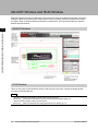
ADJUST Window and RUN Window
After test measurement and remeasurement are performed, check the measurement results. If there are
problems, adjust the processing item setting values of the processing units.If the measurement results
are stable, switch to the RUN window and perform measurement. This section describes the ADJUST
window and RUN window.
ADJUST Window
3
Performing Test Measurement/Starting Operation
RUN Window
There are two types of RUN windows: Normal mode and fast view mode. Change the display speed
according to the intended use.
Note
●
●
60
Switching method for RUN window normal mode and fast view mode
Reference:
Switching the RUN Window to Fast View Mode [Select RUN mode] (p.74)
Method for setting display contents of RUN window
Reference:
Setting the RUN Window Display [RUN Mode View Setting] (p.114)
ADJUST Window and RUN Window
FZ3 User's Manual
Normal Mode RUN Window
3
Fast View Mode RUN Window
Simplifies display items and makes the display speed faster.
FZ3 User's Manual
ADJUST Window and RUN Window
61
Performing Test Measurement/Starting Operation
When processing is taking a long time, it is necessary to check processing items and setting values. The
time required for measurement is also displayed with the measurement results, so use this for reference.
Switching to the RUN Window
1.
Tap [Switch to RUN mode] in the ADJUST window.
3
Performing Test Measurement/Starting Operation
Window switches to the RUN window.
Note
You can make settings so that the RUN window is displayed whenever power to the controller is turned on.
Reference:
Setting the Start-up Status [Startup Setting] (p.112)
Lighting gradually gets darker if it is used for a long time, so adjust judgement conditions periodically.
Without stopping a measurement in operation, you can change judgement conditions for a processing unit set
in a scene.
Reference:
Changing Judgement Conditions without Stopping Measurement (p.79)
●
●
●
Switching to the ADJUST Window
1.
Tap [Switch to ADJUST mode] in the RUN window tool box.
Switches to the ADJUST window.
62
ADJUST Window and RUN Window
FZ3 User's Manual
Performing Test Measurement
Test whether the intended measurement processing can be performed with the current setting
contents.Look at test results and adjust the property settings of each processing unit.
Perform measurement according to the conditions set in the displayed scene.
1.
2.
Display the Main screen (ADJUST window).
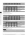
For the test conditions on the ADJUST window, set the following items.
3
3.
Performing Test Measurement/Starting Operation
Setting item
Description
Output
Place a check here when the measurement results on the ADJUST window are also
to be output.Remove the check when test measurement for the device only is to be
performed without results being output.
Continuous
meas.
Place a check here when continuous measurement is to be performed.
Tapping the [Measure] button starts continuous measurement.
Tap [Measure] in the Toolbar.
Measurement is performed.
Note
●
4.
5.
With continuous measurement, the [Measure] button changes to the [Stop meas.] button during the
measurement.To stop continuous measurement, tap [Stop meas.].
Check measurement results.
If necessary, adjust the setting values for each processing unit again.
Moving to the property window can be done directly by tapping the button of any processing unit
set in the flow.
FZ3 User's Manual
Performing Test Measurement
63
3
Performing Test Measurement/Starting Operation
Note
●
Test images can be saved.This function is called the logging function. After setting conditions, these test
images can be used in performing test measurement again.
Reference:
Logging Measurement Values and Measurement Images (p.82)
Important
●
64
The measurement interval and display update interval will vary for continuous measurement with test
measurement settings and continuous measurement with serial commands/parallel commands.
Evaluate the measurement interval and display update interval by watching actual operation.
Performing Test Measurement
FZ3 User's Manual
Key Points for Adjustment
This section describes key points for adjustment when aiming to improve measurement precision and
shorten measurement time.
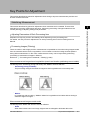
Stabilizing Measurement
This section describes key points for adjustment when measurement is not stable. There are two
methods for improving measurement precision: Performing processing of images loaded from the
camera (filtering) or adjusting settings and parameters.
3
Adjustment to improve precision and stability varies depending on the processing item.
For details, see "Key Points for Adjustment" for each processing item in the Processing Item List
Manual.
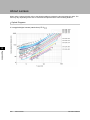
Processing Images (Filtering)
There are cases in which high-precision measurement is impossible such as when using images loaded
from the camera that have noise, irregularities, or low contrast or when the background has patterns
during defect measurement. In this case, measurement accuracy can be improved by performing
processing of measurement images in advance.
Reference:
"Processing Item List Manual", "Filtering" (p.290)
When measurement images have irregularities (search and location positioning are not stable)
The filtering items "Smoothing (strong and weak)" and "Median" are both effective.
●
●
Smoothing (strong and weak)
This processing changes the shade of images so that irregularities are not as easily seen.
Median
In comparison with smoothing, "Median" allows for irregularities to be hidden without having to
shade the edges of images.
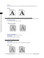
When measurement images contain noise
The filtering items "Dilate" and "Erosion" are both effective.
●
Dilate
When there is dark noise in an image, bright areas are enlarged to eliminate dark noise.
FZ3 User's Manual
Key Points for Adjustment
65
Performing Test Measurement/Starting Operation
Adjusting Parameters of Each Processing Item
●
Erosion
When there is bright noise in an image, bright areas are contracted to eliminate bright noise.
3
Performing Test Measurement/Starting Operation
When contrast of measurement images is low (defect inspection is unstable)
The filtering items "Extract vertical edges", "Extract horizontal edges", and "Extract edges" are effective.
●
●
●
Extract vertical edges
This extracts the vertical edges of an image.
Extract horizontal edges
This extracts the horizontal edges of an image.
Extract edges
This extracts the all edges of an image.
When unidentifiable shapes are present
The filtering item "Extract edges" is effective.
●
66
Extract edges
This is used to make the profile clearer and the shape more identifiable.
Key Points for Adjustment
FZ3 User's Manual
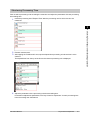
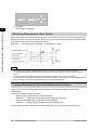
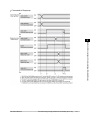
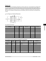
Shortening Processing Time
Find out which processing units are taking the most time and adjust the parameters of these processing
items taking time.
1.
Insert the processing item "Elapsed Time" after the processing unit for which time is to be
measured.
3
Performing Test Measurement/Starting Operation
2.
3.
Execute measurement.
4.
Adjust the parameters of the processing units that are taking time.
For details on adjustment parameters, see "Key Points for Adjustment" for each processing item
in the Processing Item List Manual.
After tapping the "Detail result" area, tap the elapsed time processing unit where time is to be
checked.
The elapsed time from the top of the flow to the relevant processing unit is displayed.
FZ3 User's Manual
Key Points for Adjustment
67
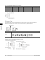
Arranging the RUN Window
Displaying Multiple Windows Together
Multiple images can be displayed side by side in the Image Display area.
3
1.
Performing Test Measurement/Starting Operation
In "Image display" of the Main screen Control area, tap [
] of the "Image layout" menu and
select the number of images to be displayed.
The camera image view in the Image Display area switches according to the selected contents.
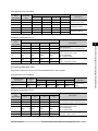
There are the following four image display patterns.
Item
Description
Displays 1 image. Since images are enlarged, this is ideal for checking details.
1 image
2 images are displayed side by side.
Suitable for when 2 cameras are connected and images are to be checked all at one
time.
2 images
68
Arranging the RUN Window
FZ3 User's Manual
4 images are viewed together with one each at the left, right, upper, and lower
positions.
4 images
3
Performing Test Measurement/Starting Operation
Suitable for when 4 cameras are connected and images are to be checked all at one
time.
Displays four small images at the bottom and also one larger selected image.
This view is preferable when you wish to check details of a certain image when four
cameras are connected.
Thumbnail display is not available in the RUN window (Fast view mode). When using
the thumbnail display in the ADJUST window, the display will change to 4 images if
you switch to the RUN window (Fast view mode).
Thumbnail
2.
Select which processing unit image to display for each image.
After tapping the display assignment to change, tap the relevant processing unit in the
measurement flow.
Changing Display Contents
The display contents of the Image Display area can be changed in order to make the measurement
status easier to understand.
1.
Tap the image to be changed.
FZ3 User's Manual
Arranging the RUN Window
69
2.
From the measurement flow, tap the processing unit to be displayed.
3.
Set each item in [Image display] of the Control area.
3
Performing Test Measurement/Starting Operation
Item
Description
Image mode
This item changes the camera image mode.
Reference:
Image Mode List (p.70)
Positions
Measurement results are displayed as a list in the Image Display area.
Display contents are classified into "Input image" units such as [Camera Image
Input] and [Camera Switching], and "Compensate image" units such as [Filtering]
and [Position Compensation].
For example, if "Positions" is turned on with [Position Compensation] selected, a
combined positions list for units after [Position Compensation] is displayed. The units
in the area before [Position Compensation] are not displayed.
Sub image
Indicates displayable image for the selected processing item.
Reference:
List of sub image numbers (p.72)
Note
●
To check detailed results for each unit when "Positions" is on, select any unit after selecting the "Detail
result" area to make detailed results active.To make detailed results inactive, select the Image Display
area.
Image Mode List
Changes can be made in the ADJUST window.
Item
Description
Through
The latest image is always loaded from the camera and displayed.
When "Through" is selected, saved images cannot be called up for measurement.
Freeze
The image that was scanned in the immediately preceding measurement is displayed. Images can
be updated at any time during measurement.
70
Arranging the RUN Window
FZ3 User's Manual
Last NG
The latest NG error image resulting from an overall judgement is displayed.
The latest measurement results are always shown in overall judgement and measurement time. In
this case, the overall judgement result and measurement time may conflict with the camera images.
Also, during continuous measurement, "Last NG" cannot be displayed.
Note
●
●
FZ3 User's Manual
Arranging the RUN Window
71
3
Performing Test Measurement/Starting Operation
●
Tapping the Image Display area or flow when "Last NG" is displayed and made active clears the screen.Be sure
to capture "Last NG" before performing any other operation.
If a measurement trigger is input during multi-input status or immediately after BUSY is turned off (during
display update processing, etc.), "Last NG" cannot be displayed.
[Display Last NG Image] fulfills a similar function as a processing item in which up to 4 NG error images can be
saved.If this processing item is used, "Last NG" can be acquired without operation having any effect on
acquisition.
List of Sub Image Numbers
Classification
Processing item
Sub image number and display
ECM Search
0: Measurement image
1: Measurement image displayed with matching edges
overlaid
Edge Position
0: Measurement image
1: Profile display
3
Edge Pitch
0: Measurement image
1: Profile display
Performing Test Measurement/Starting Operation
Scan Edge Position
0: Measurement image
1: Scan region
Scan Edge Width
0: Measurement image
1: Scan region
Gravity and Area
0: Measurement image
1: Extracted image
Labeling
0: Measurement image
1: Extracted image
Labeling+
0: Measurement image
1: Color extraction image
Defect
0: Measurement image
1: Defect profile [when area measurement is present]
Precise Defect
0: Measurement image
1: Defect profile [when area measurement is present]
Fine Matching
0: Measurement image
1: Difference image display
Measurement Image Switching
0: Reset image
1: Measurement image
Position Compensation
0: After compensation
1: Before compensation
Trapezoidal Correction+
0: Post-conversion image
Extract Color Filter
0: Color extraction image
1: Measurement image
Stripes Removal Filter+
0: Post-conversion image
Halation Cut+
0: Color extraction image
Panorama+
0: Post-combination image
Polar Transformation
0: Post-conversion image
1: Measurement image
Display Image File
0: Image 0
1: Image 1
2: Image 2
3: Image 3
Display Last NG Image
0: Last NG
1: Previous NG error image (Displayed when there are 2
or more saved images. Otherwise, "Last NG" is
displayed.)
2: NG error image from 2 previous (Displayed when
there are 3 or more saved images. Otherwise, "Last NG"
is displayed.)
3: NG error image from 3 previous (Displayed when
there are 4 or more saved images. Otherwise, "Last NG"
is displayed.)
2D measurement
72
Arranging the RUN Window
FZ3 User's Manual
Enlarging Measurement Images [Zoom Images]
Set the measurement image zoom status (magnification and display position).During display of multiple
images, magnification can be set for each image.
1.
On the Main screen, tap [View] - [Zoom images].
A magnification setting tab is displayed in the top right of the measurement image.
3
Set the magnification as required.
Set value
[Factory default]
Setting item
●
●
●
Measurement image magnification
setting
●
●
●
●
●
3.
4.
Performing Test Measurement/Starting Operation
2.
Description
[Auto]
25%
50%
100%
200%
400%
800%
1600%
Sets magnification.
Drag images to specify the display position as required.
On the Main screen, tap [View] - [Zoom images].
The current magnification and display position are saved.
Displaying Flow and Detailed Results
Switches display of [Flow] and [Detail result] on/off of in the Control area.
Note
●
The same operation is available by tapping [View] - [Flow] or [Detail result].
1.
Tap [Flow] or [Detail result] in the Control area.
Flow or details of measurement results are displayed. Tapping once again returns the screen to
the previous status.
FZ3 User's Manual
Arranging the RUN Window
73
3
Performing Test Measurement/Starting Operation
2.
When displaying both the flow and detailed results, you can change the size of the Display area
of the flow and detailed results by dragging [Detail result].
Switching the RUN Window to Fast View Mode [Select RUN Mode]
Switches the mode of the RUN window.Fast view mode simplifies display items and makes the display
speed faster.
1.
2.
74
On the Main screen, tap the [System] menu - [Controller] - [Select RUN mode].
The Select RUN Mode window is displayed.
Tap [
] and select a mode.
Arranging the RUN Window
FZ3 User's Manual
Set value
[Factory default]
●
●
3.
[RUN - normal mode]
RUN - fast view mode
Description
Selects which mode is used to display the RUN
window.
Tap [OK].
The Select RUN Mode window closes.
Changing Display Contents on the RUN Window
Measurement Information Display Area
3
Performing Test Measurement/Starting Operation
The display contents on the RUN window measurement information display area can be changed.
Reference:
Setting the RUN Window Display [RUN Mode View Setting] (p.114)
Changing Functions That Can Be Operated from the RUN Window
Tool Box
Functions that can be operated from the RUN window tool box can be changed.
Reference:
Setting the RUN Window Shortcut [Create Shortcut] (p.115)
FZ3 User's Manual
Arranging the RUN Window
75
Useful Functions for Operation
Remeasuring Saved Images
3
Performing Test Measurement/Starting Operation
Images from when measurement, including test measurement, was performed can be
saved.Remeasurement can be performed with saved images after conditions are adjusted in order to
check whether the adjustment is appropriate.
The logging function is used for saving images.
Reference:
Setting Logging Conditions [Logging Setting] (p.84)
Images that can be remeasured include images saved in the controller and images saved in USB
memory.
1.
2.
3.
In the Control area of the Main screen, tap [Test measurement].
Tap [Select image].
The Select Image window is displayed.
Tap [...] and select the file to display.
Setting item
4.
76
Description
File
Specify images saved in the USB memory or in the RAMDisk.
Logging image
Specify images that are logged in the controller memory.
The selected image is displayed at the lower left of the FileExplorer screen.
When there are multiple camera images in a file, as for a logging image when multiple cameras
are connected, use the "<<" and ">>" buttons to switch images.
Useful Functions for Operation
FZ3 User's Manual
5.
6.
Tap [OK].
The path and file name of the image are displayed under [Select image].
Check "Measure using selected img (Re-meas.)".
3
Tap [Measure] in the toolbar on the Main screen.
Measurement of the selected image is performed.
Note
●
About Auto Re-meas.
Displayed images can be automatically remeasured by placing a check in "Auto Re-meas.".
Important
●
When remeasuring an image with the controller, it is necessary to have a camera connected that is
appropriate to the image size.For example, if the image file for remeasurement contains 2 megapixel
images and a 0.3 megapixel camera is connected to the controller or if a camera is not connected,
measurement will not be performed correctly due to a memory deficiency.Perform remeasurement after
connecting a camera appropriate to the image size.
Improving Adjustment Efficiency
Convenient when measuring a large amount of image samples and classification or adjustment is
performed with each judgement.
Files in which NG error files and OK files are mixed can be continuously remeasured automatically, with
the system stopping at images with a specified condition (OK/NG) and these files being moved.
1.
2.
In the Control area of the Main screen, tap [Test measurement].
Place a check next to "Monitoring Judgement" and set the judgement conditions for
identification.
If the specified judgement condition is achieved when continuous measurement is performed,
measurement stops and the following message is displayed.
FZ3 User's Manual
Useful Functions for Operation
77
Performing Test Measurement/Starting Operation
7.
If OK is selected
3
If NG is selected
Performing Test Measurement/Starting Operation
3.
Select the processing for the measured image.
For "Adjust setting"
Tap the [Adjust setting] button.
For "Move Image file"
Specify the save destination and tap [OK].
78
Useful Functions for Operation
FZ3 User's Manual
3
Performing Test Measurement/Starting Operation
Tap the [Move Image file] button.
Tap the [Skip] button to skip processing and remeasure the next image.
Changing Judgement Conditions without Stopping Measurement
Using the simplified non-stop adjustment function makes it possible to change the judgement conditions
of processing units of the currently displayed scene without stopping the measurement processing being
executed.
Note
●
●
The simplified non-stop adjustment function can only be used in RUN window normal mode.It cannot be used in
the ADJUST window or RUN window fast view mode.
If the Enter Simplified Non-stop Adj. button is not displayed, the button can be added with the [System/
Controller/Create shortcut].
1.
2.
In the Control area of the Main screen (RUN window), tap [Tool box].
Tap [Enter simplified non-stop adj.].
Transfers to simplified non-stop adjustment mode."Simplified non-stop adjustment" is displayed
at the upper part of the Control area flow.
Measurement will continue without stopping.
FZ3 User's Manual
Useful Functions for Operation
79
3.
Tap the icon of the processing unit with the judgement condition to be adjusted.
3
Performing Test Measurement/Starting Operation
The window for the judgement conditions of the selected processing unit is displayed.
4.
5.
6.
80
If you tap the icon of a processing unit that does not have a "Judgement condition" setting item, a
Judgement window is not displayed.
Change the judgement conditions of each processing unit.
Tap [OK].
The Judgement window closes, and the screen returns to the Main screen.
The changed contents are shown in the displayed scene.
When changing judgement conditions for multiple processing units,
repeat steps Reference: 3 (p.80) to Reference: 5 (p.80) .
In the Control area of the Main screen, tap [Quit simplified non-stop adj.].
Useful Functions for Operation
FZ3 User's Manual
The simplified non-stop adjustment mode ends.
Note
●
If [Switch to ADJUST mode] is tapped while executing simplified non-stop adjustment, the simplified
non-stop adjustment mode is automatically ended and the screen switches to the ADJUST window.
Changing Regions as a Batch [Shift area]
3
1.
Tap [Shift area] in the Edit Flow window.
The Move Measuring Area at Once window is displayed.
2.
Select the processing item in which to change the region.
Only image setting processing items included in "Input image" and "Compensate image" are
displayed.
3.
Select the registration region to change.
4.
Tap [Move] and input the value or tap the arrows to move the image.
Images can also be directly dragged and moved.
FZ3 User's Manual
Useful Functions for Operation
Performing Test Measurement/Starting Operation
Figure data for multiple processing items can be changed as a batch.
81
5.
3
Tap [OK].
The change is registered.
Performing Test Measurement/Starting Operation
Monitoring Measurement Value Trends
By monitoring the trend in measurement values, the occurrence of defects can be prevented in advance
and this information can also be helpful in NG error occurrence cause analysis.Use the processing item
[Trend Monitor] to monitor the measurement values.
Reference:
"Processing Item List Manual", "Trend Monitor" (p.363)
Note
If the measurement value is within the alarm range, the "Warning" message is shown on the screen.
If a result output-related processing item is used, this allows for output to external devices when a warning
occurs.
Through trend monitor judgement, trends can be managed and NG error images can be saved.
To save only NG error images identified by trend monitor judgement, create settings so that overall judgements
from processing units other than [Trend Monitor] are not included in judgement.
●
●
●
Logging Measurement Values and Measurement Images
Logging is a function for saving camera input images or measurement results when executing
measurement.
There are two different logging methods.
●
●
When logging images that are currently displayed
Reference:
Logging current image [Save last logging image] (p.83)
When automatically logging images during measurement
Reference:
Setting Logging Conditions [Logging Setting] (p.84)
Images and measurement data can be saved in USB memory, which makes them useful for the
82
Useful Functions for Operation
FZ3 User's Manual
following kinds of adjustment.
3
Performing Test Measurement/Starting Operation
Logging Current Image [Save Last Logging Image]
This section explains the method for logging the latest input image being displayed.
1.
On the Main screen, tap [Measure] - [Save last logging image].
The Logging Setting window is displayed.
FZ3 User's Manual
Useful Functions for Operation
83
3
Performing Test Measurement/Starting Operation
2.
3.
Set the logging images save destination.
Specify the image file save destination (RAMDisk or USB memory).
Edit the file name as required.
4.
Tap [OK].
After the logging operation is complete, the Save Last Logging Image window closes.
Setting Logging Conditions [Logging Setting]
Set the logging timing and the save destination.
1.
2.
84
On the Main screen, tap the [Measure] menu - [Logging setting].
The Logging Setting window is displayed.
Set the logging conditions for images.
Useful Functions for Operation
FZ3 User's Manual
Set value
[Factory
default]
Setting item
Image
Logging
[None]
No images are saved.
When logging images with the processing item "Image Logging",
select [None].
Only NG
Only images with an overall judgement of NG are saved.
All
All measured images are saved.
Note, however, that some images may not be saved if "Measurement"
is set in "Logging priority" in step 4.
3
Set the logging images save destination.
Note
●
In order to perform fast logging, image files are first saved in the controller memory.Note, however, that
the controller memory for saving images is a ring memory. If the maximum number of save images is
reached, images will be overwritten starting with the oldest saved image if further images are saved.
Reference:
About Number of Logging Images (p.292)
Also, the controller memory is cleared if the power is turned off.
To keep images, select "Save to memory + file" and save images to USB memory, etc.
Set value
[Factory default]
Setting item
Destination
Description
[Save to memory]
Saves to the controller memory.
Save to memory + file
Images saved to the controller memory are saved to a
USBDisk or RAMDisk as files.
When "Save to memory + file" in "Destination" is selected, set the destination and file names.
Set value
[Factory default]
Setting item
●
Folder name
Prefix
Switch
saving folder
by scene
Switch
saving folder
by judge
FZ3 User's Manual
●
[RAMDisk]
USBDisk
Description
Specify the image file save destination (RAMDisk or USB
memory).Logging images are saved in the specified save
destination folder.
Set the prefix for the save file name.
The set character string is added at the beginning of the name
of the save file.
—
●
●
●
●
Checked
[Unchecked]
If checked, folders that correspond to scene numbers are
automatically created and image files are divided by scene
and saved.
Checked
[Unchecked]
If checked, OK/NG folders are automatically created and
image files are divided by scene and saved.
Useful Functions for Operation
85
Performing Test Measurement/Starting Operation
3.
Description
"Save to memory + file" setting example and save destination
Example of setting
●
●
●
●
3
4.
Save destination
Folder name: USBDisk
Prefix: image_
"Switch saving folder by scene":
Checked
"Switch saving folder by judge":
Checked
Saving will be performed as follows for the settings example
on the left
OK image save destination:
\USBDisk\S000-000\OK\image_(Measurement ID).IFZ
NG error image save destination:
\USBDisk\S000-002\NG\image_(Measurement ID).IFZ
●
●
Performing Test Measurement/Starting Operation
Set the image logging priority conditions.
This setting is only valid when "Save to memory + file" is selected in the image logging saving
conditions.
When the measurement tact time is short, time lag may occur with writing from the controller
memory to the RAMDisk or USBDisk and temporary absences of free space in the controller
memory may occur.Select whether logging or measurement has priority at these times.
Setting item
Set value
[Factory
default]
[Logging]
Logging
priority
5.
86
Description
When there is no free capacity in the controller memory, subsequent
measurement cannot be received until free capacity becomes
available.
All measurement target images are logged, but the measurement tact
time becomes longer.
Measurement will continue even if there is no free capacity in the
controller memory.New logging is not performed until free capacity
Measurement becomes available in the controller memory.
The measurement tact time is maintained, but some measurement
may not be logged.
Set the data logging conditions.
The data format is set with the processing item "Data Logging".
Useful Functions for Operation
FZ3 User's Manual
Setting item
Data
Logging
6.
Set value
[Factory
default]
Description
[None]
Measurement data is not saved.
Only NG
Measurement data is saved when an NG error occurs in a unit before
"Data Logging".If an NG error occurs after the "Data Logging"
processing unit, data logging is not performed.
All
All measurement data is saved.
3
Set the logging data save destination.
Set value
[Factory default]
●
Folder name
●
[RAMDisk]
USBDisk
Performing Test Measurement/Starting Operation
Setting item
Description
The data is saved in the specified destination folder (RAMDisk or
USBDisk).Set the file name with the processing unit [Data
Logging].
Note
About loading data to a PC
Factory settings are set so that logging data is saved in the controller RAMDisk.
When logging data is loaded to a PC, set USBDisk as the save destination.
Logging data is first saved to the controller RAMDisk and then can be copied from the RAMDisk and
saved to the USBDisk using "Copy files" in "Save to file".
●
7.
Tap [OK].
Settings are confirmed and the Logging Setting window closes.
Important
●
●
Logging images saved in the controller memory are overwritten starting with the oldest image if the upper limit
for the number of save images is exceeded.
Reference:
About Number of Logging Images (p.292)
The data saved in the controller memory or RAMDisk is deleted when the controller is restarted.
FZ3 User's Manual
Useful Functions for Operation
87
Note
About image logging
When the number of files in the save destination folder increases, the time needed for image saving increases.
If [Camera Image Input] is used several times in a flow, the image from the last [Camera Image Input] is saved.
About number of images that can be saved
This will vary depending on the size of the images and the resolution of the connected camera.
The number of images that can be saved on the RAMDisk or USBDisk depends on free capacity.
If RAMDisk is selected, this depends on the controller memory capacity.
If USBDisk is selected, this depends on the USBDisk capacity.
The following methods can be used to increase the number of images that can be saved on the RAMDisk or
USBDisk.
Shorten file names when saving directly under the root directory.
When saving image files directly under the root directory, the number of images that can be saved is about
126 due to FAT file format limitations.If file names are shortened, this can be increased to a maximum of
512.
Save in sub-folders
When saving in sub-folders (\USBDisk\SUB, etc.) and not in the root directory, a maximum of 999 images
can be saved in each folder.
●
●
●
●
●
●
3
●
Performing Test Measurement/Starting Operation
●
●
Analyzing Logging Data
Acquired data is referred to and processed, and settings are analyzed.
Checking Logging Data with a PC
This section uses the example of saving logging data in the USB memory.
88
1.
2.
Copy logging data saved to the USB memory to the PC.
3.
Open using an application associated with the extension (csv).
Explanation is given here using examples displayed in Excel.
Open folder with copied data.
Useful Functions for Operation
FZ3 User's Manual
3
Performing Test Measurement/Starting Operation
4.
Use Excel graphing and functions to process and analyze data.
For example, the optimum threshold value can be calculated.
Comparing Logging Data and Logging Images
Compare image and measurement data to confirm correctness and to make analyzing trends for when
NG occurs easier.
The measurement data and image data stored through the logging function is associated through
FZ3 User's Manual
Useful Functions for Operation
89
measurement IDs based on the measurement date and time.
In this way, measurement data can be made to always correspond with image data.
Verify data with the measurement ID.
3
Performing Test Measurement/Starting Operation
Clearing Measurement Results
Clears all of the currently displayed scenes.
This function sets the expression which calculates the measurement count, and is convenient when that
count is to be reset.
1.
2.
On the Main screen, tap [Measure] - [Clear measurement].
A confirmation window is displayed.
Tap [OK].
The measurement results are deleted.
Clearing Saved Images
Clears all of the logging images that are currently logged in the controller.
1.
2.
90
On the Main screen, tap the [Measure] menu - [Clear logging image].
A confirmation window is displayed.
Tap [OK].
Useful Functions for Operation
FZ3 User's Manual
Note
●
If you want to keep the logged images as files, save the logged images to the USB memory device by tapping
[Data] - [Save to file] - [Logging image] before clearing them.
Reference:
Saving Logging Images to RAMDisk/USB Device (p.100)
Capturing Screens
The contents displayed in the monitor screen can be captured.Saved images can be loaded into the PC
and pasted to documents.
●
Capture takes a few seconds and measurement cannot be performed at this time.
1.
Open the measurement manager bar at the bottom right of the Main screen and tap [Capture].
Note
●
The same operation can also be performed by tapping the [System] menu - [Screen capture] - [Screen
capture].
About capture image files
This section explains the format and file names for capture images.
With factory settings, capture images are saved to the RAMDisk.The save destination can be changed.
Item
Description
File format
The file format is BMP.
File name
The file name is the date and time at which capture was performed.
YYYY-MM-DD_HH-MM-SS-MS.BMP
Year (4 digits) -Month- Date_ Hour- Minute- Second- Millisecond
Example)
The file name for a capture date and time of 3/10/2007, 11:25:30.500:
2007-03-10_11-25-30-500.BMP
Note
●
The following windows cannot be captured.
The window to select a file or a folder
Confirmation message window when LCD is turned off
●
●
FZ3 User's Manual
Useful Functions for Operation
91
Performing Test Measurement/Starting Operation
Important
3
Setting the Save Destination for Captured Images
Sets the save destination for the image captured with the screen capture function.
1.
2.
On the Main screen, tap the [System] menu - [Screen capture] - [Screen capture setting].
The Screen Capture Setting window is displayed.
Specify the save destination for captured images.
3
Performing Test Measurement/Starting Operation
3.
92
Tap [OK].
The settings are determined and the Screen Capture Setting window closes.
Useful Functions for Operation
FZ3 User's Manual
Saving/Loading Data
4
Reference: Basic Knowledge about Data Saving (p.94)
Reference: Saving Settings Data to Controller Memory (p.96)
Reference: Saving Settings Data to RAMDisk/USB Device (p.98)
Reference: Saving Logging Images to RAMDisk/USB Device (p.100)
Reference: Copying/Moving Files (p.101)
Reference: Loading Settings Data to Controller (p.103)
FZ3 User's Manual
93
Saving/Loading Data
This chapter explains methods for saving and loading
settings data and image data.
Basic Knowledge about Data Saving
This section explains methods for saving and loading settings data and image data.
About Saving Areas
The following saving areas can be used with this device.
Saving area
4
Saving/Loading Data
Flash
memory
Settings data is saved in this area.Data is held even after the power is turned off.
On-board
memory
This is the area where images are temporarily stored when logging images using the
logging function.
This memory is a ring memory, and images will be overwritten starting with the oldest
image if the maximum number of save images is exceeded.
RAM disk
Can be used as a temporary file save destination.Data is cleared if the controller
power is turned off.
The RAMDisk data can be sent to or received from external devices using the FTP
function.
Controller
USB memory
Description
Used to back up settings data as a precaution, to copy settings data to another
controller, and to load data to a PC.To keep data, save to the USB memory before
turning off power to the controller.
Important
During data transfer, do not turn off the power.
When a message indicating that processing such as saving or loading is in progress is displayed, do not restart
the controller or turn off the power. Data will be corrupted and the system will not work properly at the next
startup.
Do not remove USB memory devices during saving or loading.Operation of the controller may damage data or
the USB memory.
Do not change the extension of saved files. If changed, the file cannot be loaded as the setting data. In addition,
if setting data in which the extension was changed is loaded, the system may not work properly later.
Depending on the settings, saving may fail due to insufficient USB memory capacity.If saving fails and the error
message "Please check." appears, check to see if there is unnecessary data in the USB memory and save after
this data has been deleted.
●
●
●
●
About USB Drive Names
The controller is equipped with 4 USB connectors. If multiple USB memory devices are plugged in,
specify the USB memory drive that is to be the destination.
The drive names of USB memory devices are called USBDisk, USBDisk2, USBDisk3 and USBDisk4
according to the sequence in which devices are inserted into the controller.
If the controller, however, is started with more than one USB memory device inserted, drive names will
be assigned based on the ports in which the USB memory devices are inserted. Depending on the
controller type, USB memory devices are recognized and named using the following sequence.
●
●
94
Controller integrated with LCD
1: Left side of the front → 2: Right side of the front → 3: Front of the side face → 4: Back of the
side face
Box-type Controller
1: Lower left of the front → 2: Lower right of the front → 3: Upper left of the front → 4: Upper
right of the front
Basic Knowledge about Data Saving
FZ3 User's Manual
Important
When the BOX controller is used
If USB memory devices are separately connected to adjacent USB interfaces, the contact between USB
memory devices may possibly lead to failure or damage.
●
4
Saving/Loading Data
FZ3 User's Manual
Basic Knowledge about Data Saving
95
Saving Settings Data to Controller Memory
Saves system data and scene group data on the controller's flash memory. Make sure to save settings
data when settings have been changed.
Important
If "Save to file" is performed for system + scene group 0 data, the data being saved will also be saved to the
controller flash memory at the same time.Do not turn off the power during processing. The controller may not
start up properly the next time it is turned on.
During data transfer to USB memory, do not remove the USB memory device until transfer is completed. Data
and/or the USB memory may be corrupted.
●
●
4
Saving/Loading Data
Note
When using scene groups 1 to 31, only system data can be saved in the controller flash memory. Note,
however, that if a USB memory device is plugged in, scene group data can be saved to the USB memory.
●
When Using Scene Group 0
1.
On the Main screen, tap [Data save] in the toolbar.
A confirmation message is displayed.
Note
●
2.
The same operation is available by tapping [Data] menu - [Data save].
Tap [Yes].
System data and scene group data are saved on the controller's flash memory.
When Using Scene Groups 1 to 31
1.
2.
3.
Plug a USB memory device into the controller.
On the Main screen, tap [Data save] in the toolbar.
A confirmation message is displayed.
Tap [Yes].
System data is saved to the controller's flash memory and scene group data is saved to the USB
memory, respectively.
The data from scene groups 1 to 31 is saved to the USBDisk.
When multiple USB memories are connected to the controller, check in the file explorer window,
etc. that the USB memory where scene group data is to be saved is recognized as the USBDisk.
Reference:
About USB Drive Names (p.94)
96
Saving Settings Data to Controller Memory
FZ3 User's Manual
Note
●
If a USB memory device is not plugged in, a check message is displayed.
If [OK] is tapped, only system data is saved in the controller flash memory.
4
Saving/Loading Data
FZ3 User's Manual
Saving Settings Data to Controller Memory
97
Saving Settings Data to RAMDisk/USB Device
Saves the setting data file to the RAM Disk or USB memory. The data that can be saved is as follows.
Data
4
Description
Saving/Loading Data
System data
(*.ini)
Settings data, such as the [System] menu settings contents, which is shared within the
controller
Scene data
(*.scn)
Data for each scene. Sequence of units set in each scene and setting values of units
within scenes.
Scene group data
(*.sgp)
The data of scene group with 32 scenes.
System + Scene group 0
data
(*.bkd)
Data combining the system data and the data from Scene Group 0.
Important
●
During saving, do not restart, turn off power or remove the USB memory.Data will be corrupted and the system
will not work properly at the next start-up. It is especially necessary to pay attention when "Save to file" is being
performed for system + scene group 0 data, as the data being saved will also be saved to the controller flash
memory at the same time.
Note
●
When "Save to file" is executed, the data to save is also saved in the controller (except Scene Group Data 1 to
31).
1.
2.
98
When saving to USB memory, plug a USB memory device into the controller.
3.
On the Main screen, tap [Data] - [Save to file].
The Save to File window is displayed.
Tap [Setting data] and select the data to save.
4.
When scene data is selected, tap [
5.
Specify the save destination folder and file name.
] to select the scene number that is to be the save target.
Saving Settings Data to RAMDisk/USB Device
FZ3 User's Manual
6.
Tap [OK].
The window showing transfer status is displayed, and the data is sent to the save destination.
4
Saving/Loading Data
FZ3 User's Manual
Saving Settings Data to RAMDisk/USB Device
99
Saving Logging Images to RAMDisk/USB Device
Logged image data in the controller memory is saved to RAMDisk or USB memory.
Reference:
About Saving Areas (p.94)
1.
2.
3.
When saving to USB memory, plug a USB memory device into the controller.
On the Main screen, tap [Data] - [Save to file].
The Save to File window is displayed.
Tap [Logging image] and select the file to save.
4
Saving/Loading Data
Setting item
Data to be
saved
Setting value [Factory
default]
Description
[All logging image]
Saves all the logging images.
Select image
Saves the selected logging image.
Tap [
] and select the image to save.
4.
Specify the save destination folder.
5.
Tap [OK].
The window showing transfer status is displayed, and the data is sent to the save destination.
100
Saving Logging Images to RAMDisk/USB Device
FZ3 User's Manual
Copying/Moving Files
Files can be copied or moved between the controller RAM Disk and USB memory.
Images and data saved on the RAM Disk are deleted if the power is turned off. If you wish to keep these
images and data, copy or move them to the USB memory. The types of files that can be copied/moved
are as follows:
●
●
●
3.
4
Plug a USB memory device into the controller.
On the Main screen, tap [Data] - [Save to file].
The Save to File window is displayed.
Tap [Copy files] and select the file or folder to copy or move.
Setting item
Setting
value
[Factory
default]
Saving/Loading Data
1.
2.
Settings data (scene data, scene group data, system data)
Logging Image
Logging data
Description
[Select
folder]
Copies or moves multiple files in a folder.
Tap [...] and specify the source folder to copy/move.
Tap [
] and select the file format.
If [All files] is selected, you can copy or move all files in the folder.
When any of the file formats is selected, you can specify the type
of files (extension) in the folder to copy or move.
Select file
name
Copies or moves the selected file.
Tap [...] and specify a file name.
●
Select file
4.
●
If you wish to delete the source file after saving a copy to USB memory, check "Delete original
data after save".
FZ3 User's Manual
Copying/Moving Files
101
5.
Tap [OK].
The window showing transfer status is displayed, and the data is sent to the save destination.
4
Saving/Loading Data
102
Copying/Moving Files
FZ3 User's Manual
Loading Settings Data to Controller
Loads the settings data saved in an external device to the controller. The scene name and scene group
name that have been loaded are displayed in the measurement information display area.
Note
●
If "Load from file" is performed for system + scene group 0 data, the data being loaded will also be saved to the
controller flash memory at the same time.During loading, do not restart, turn off power or remove the USB
memory. Data will be corrupted and the system will not work properly at the next startup.
1.
Perform either of the following.
●
2.
3.
On the Main screen, tap the [Data] menu - [Load from file].
The Load from File window is displayed.
Select the file to load.
4.
Tap [OK].
Saving/Loading Data
●
4
Plug the USB memory device which has the load data stored in it into the controller.
Send setting data to the controller's RAM Disk via FTP.
The window showing the transfer status is displayed, and the data is transferred.
FZ3 User's Manual
Loading Settings Data to Controller
103
4
Saving/Loading Data
104
Loading Settings Data to Controller
FZ3 User's Manual
Changing the System Environment
This chapter describes settings related to the controller
system environment.
5
Reference: Setting Conditions Related to Operation during Measurement (p.108)
Reference: Setting the System Operation Environment (p.110)
FZ3 User's Manual
105
Changing the System Environment
Reference: Setting Conditions for Camera Use (p.106)
Setting Conditions for Camera Use
Checking Camera Connections [Camera Connection]
Verify whether or not cameras are connected.This section includes no special settings.
1.
2.
On the Main screen, tap the [System] menu - [Camera] - [Camera connection].
The Camera Connection window is displayed.
Verify the connection status.
3.
Tap [Close].
5
Changing the System Environment
Setting Trigger Delay [Inter-camera Setting]
This creates settings for the delay from when the input trigger STEP signal is received to until the shutter
trigger occurs.When multiple cameras are used, this prevents mutual lighting interference and can be
used as a simple trigger delay when only one camera is used.
106
Setting Conditions for Camera Use
FZ3 User's Manual
Note
●
The STGOUT pulse width is set in "Electronic flash setting" of the [Camera Image Input] processing item.
Reference:
"Processing Item List Manual", "Electronic Flash Setting" (p.17)
5
2.
On the Main screen, tap the [System] menu - [Camera] - [Inter-camera setting].
The Inter-camera Setting window is displayed.
Tap [...] of each item and set values.
Item
Set value
[Factory default]
STEP - Camera 0 delay
STEP - Camera 1 delay
STEP - Camera 2 delay
STEP - Camera 3 delay
3.
Changing the System Environment
1.
[0] to 511
(1 count/30 μs)
Max. 15 ms
Description
Set delay between receiving the STEP signal
and the beginning of camera exposure.
Delay time
= count x 30 μs + 122 μs
Tap [OK].
The settings are confirmed and the Inter-camera Setting window closes.
FZ3 User's Manual
Setting Conditions for Camera Use
107
Setting Conditions Related to Operation
during Measurement
With operation during measurement, the following items can be changed.
●
●
1.
2.
5
Operation when the next STEP signal is input during measurement
Saving of scene groups during scene group switching
On the Main screen, tap the [Measure] menu - [Measure setting].
The Measurement Setting window is displayed.
Set each item as required.
When they are not displayed, create settings through the [System] menu - [Controller] - [Create
shortcut].
Changing the System Environment
Set value
[Factory default]
Item
●
STEP in measure
Save scene group on
scene switch
Scene switch time
Add time [ms]
108
●
●
●
Description
[ERROR ON]
ERROR OFF
Sets whether the ERROR signal output turns on
when the following STEP signals are input during
measurement.
[Checked]
Unchecked
Sets operation when scene group switching is
performed.Sets whether the scene group is saved
when it is switched.The scene group switching time
can be reduced if the check is removed, but if the
power is turned off without saving when settings
have been changed, the changed contents will be
cleared.
0 to 1000
[10]
The BUSY signal is turned on during scene
switching.When this time is short and the change
from ON to OFF cannot be detected by external
devices, the BUSY signal ON time can be
added.This is set in 1 ms units.The displayed value
can be changed in 5 ms increments by tapping "<"
and ">".
Setting Conditions Related to Operation during Measurement
FZ3 User's Manual
Note
●
3.
The settings of "Save scene group on scene switch" are linked with the settings of the Switch Scene
Group window.Settings specified later override the previous ones.
Reference:
Switching Scenes and Scene Groups (p.50)
Tap [OK].
The display returns to the Main screen.
5
Changing the System Environment
FZ3 User's Manual
Setting Conditions Related to Operation during Measurement
109
Setting the System Operation Environment
Sets the controller's operation environment. The following settings are available.
●
●
●
●
●
●
●
●
●
5
Reference:
Reference:
Reference:
Reference:
Reference:
Reference:
Reference:
Reference:
Reference:
Setting the Date and Time [Date-time Setting] (p.110)
Selecting the Language [Language Setting] (p.110)
Setting the Fan Rotation Speed [Fan Control Setting] (p.111)
Setting the Start-up Status [Startup Setting] (p.112)
Setting the RUN Window Display [RUN mode View Setting] (p.114)
Setting the RUN Window Shortcut [Create Shortcut] (p.115)
Setting the Encoder Trigger [Encoder Trigger Setting] (p.115)
Setting the STEP Input Detection Pulse Width [STEP Setting] (p.116)
Setting the RUN Window Password [Password Setting] (p.117)
In addition, the controller model and measurement application version can be checked.
Changing the System Environment
●
Reference:
Checking System Information [System Information] (p.119)
Setting the Date and Time [Date-time Setting]
Confirm that the date and time on the embedded calendar are correct, and make corrections if they are
not.
The log data dates and times, etc. are set based on contents set here.
1.
2.
On the Main screen, tap the [System] menu - [Controller] - [Date-time setting].
The Date-time Setting window is displayed.
Set the date and time.
1.
2.
3.
Tap the date that is to be set.
Set the time.
Tap [OK].
The Date-time Setting window closes.
Selecting the Language [Language Setting]
Sets the language used for the characters displayed on the screen.Messages in the application software
will be displayed in Japanese or English depending on the language selected here.
110
Setting the System Operation Environment
FZ3 User's Manual
Note
●
●
When a controller with default factory settings is started up, the Language Setting window is automatically
displayed.
The controller factory default setting is Japanese language display.If the language setting is changed to
English, the system automatically restarts.
1.
2.
On the Main screen, tap the [System] menu - [Controller] - [Language setting].
The Language Setting window is displayed.
Tap [
] and select a language.
5
4.
Changing the System Environment
3.
Tap [OK].
A confirmation message is displayed.
Tap [Yes].
The setting is saved in the controller and the system automatically restarts.After the system
restarts, the language switches to the selected one.
Note
●
The Language Setting window is displayed also when restarting after executing "System initialization".
Setting the Fan Rotation Speed [Fan Control Setting]
Sets the rotation speed of the controller fan.
Note
●
The factory default setting is low rotation.Use fast rotation when using the system in a high-temperature
environment between +45 and +50 ° C.
1.
2.
On the Main screen, tap the [System] menu- [Controller] - [Fan control setting].
The Fan Control Setting window is displayed.
Select a fan setting.
FZ3 User's Manual
Setting the System Operation Environment
111
Set value
[Factory default]
●
●
3.
[Low rotation (Ambient temperature: 0 to +45 ° C)]
High rotation (Ambient temperature: 0 to +50 ° C)
Description
Select a fan rotation
speed.
Tap [OK].
Important
●
For the FZ3-3
/FZ3-H3
series, the fan control setting is fixed at low rotation. The setting cannot be
changed to fast rotation.(Fast rotation can be selected on the screen, but the setting will not change.)
Setting the Start-up Status [Startup Setting]
5
Changing the System Environment
The status for when power is turned on is set here.
Inspection can be set to start immediately after the power is turned on by setting the scene No. of the
scene in which measurement contents are set.
In addition, settings can be done so that the Camera Setting window is not displayed at start-up.
1.
2.
112
On the Main screen, tap the [System] menu - [Controller] - [Startup setting].
The Startup Setting window is displayed.
Change the settings.
Setting the System Operation Environment
FZ3 User's Manual
Set value
[Factory default]
Item
Description
Scene
The selected scene/scene group will be the
scene/scene group at start-up.
[Unchecked]
The scene/scene group set in the controller
when "Data save" is executed will be the
scene/scene group at start-up.
Scene Group
Scene groups 0 to 31
[Scene group 0]
Selects the scene group displayed at
start-up.
Scene
Scenes 0 to 31
[Scene 0]
Selects the scene displayed at start-up.
[ADJUST]
RUN
Selects whether the ADJUST window or
RUN window is displayed at start-up.
[Open]
Close
Selects whether to display the measurement
manager bar at start-up.
Specify startup
scene, scene group
●
Select startup mode
Measurement manager
bar state
●
●
●
5
Changing the System Environment
Checked
Specifies whether measurement results
display or menu operation is to have priority.
Operation priority
[Measurement result
priority]
Measurement results display processing will
have priority over menu operation.Menu
operation will be harder to receive due to its
lowered priority status.
Menu operation priority
Menu operation is prioritized.Measurement
results display may be incomplete.
Measurement initialization is performed
immediately after scene switching or flow
editing.Specifies whether measurement
trigger receipt or screen re-drawing
processing has priority during measurement
initialization.
Measurement
initialization priority
[Measurement trigger
receipt priority]
Measurement trigger reception is prioritized
even during processing, including
measurement processing. Display for
screen re-drawing processing may be
incomplete due to its lowered priority status.
Processing of re-drawing
on screen priority
Screen re-drawing processing is prioritized.
Measurement triggers will not be received
until screen re-drawing processing is
complete.
Communication module
select
FZ3 User's Manual
Setting the System Operation Environment
113
●
●
Serial (Ethernet)
●
●
●
Serial (RS-232C/
RS-422)
Parallel
5
3.
●
[Normal]
Normal (Fxxx series
method)
PLC Link
(SYSMAC CS/CJ/CP/
One)
[Normal]
Normal
(Fxxx series method)
PLC Link
(SYSMAC CS/CJ/CP/
One)
[Standard Parallel I/O]
Sets the communication module.
Serial/Ethernet
Normal/Normal (Fxxx series method):
External devices are communicated with
using non-procedure communications. For
the differences between Normal and Normal
(Fxxx series method), see the note below.
PLC Link: Communication is performed via
a link area with the PLC.
Parallel
Standard Parallel I/O: Communication is
performed via a standard parallel interface.
Changing the System Environment
Tap [OK].
Settings are confirmed and the Startup Setting window closes.
Note
●
About "Normal (Fxxx series method)"
With the "Normal (Fxxx series method)" communication method, the OK response timing in relation to
MEASURE commands is different from that of the "Normal" communication method.
"Normal (Fxxx series method)" communication method
MEASURE
Measurement result
OK
"Normal" communication method
MEASURE
OK
Measurement result
Setting the RUN Window Display [RUN mode View Setting]
The layout of display contents and size of characters can be set.
1.
2.
On the Main screen, tap the [System] menu - [Controller] - [RUN mode view setting].
The current RUN window mode is displayed.To change the mode, specify the mode in System/
Controller/Select RUN mode .
Set items to be displayed.
3.
Set the layout as required.
114
Setting the System Operation Environment
FZ3 User's Manual
Setting the RUN Window Shortcut [Create Shortcut]
The short cut button can be added to the RUN window.The button is added to the tool box.
1.
2.
On the Main screen, tap the [System] menu - [Controller] - [Create shortcut].
Set the functions to be added.
5
Changing the System Environment
3.
Set the sequence as required.
Short cuts are added in the sequence set here.
Note
●
Some of these short cuts have functions, such as scene switching, which affect measurement.A
password protection function can be added in order to restrict use.
Reference:
Setting the RUN Window Password [Password Setting] (p.117)
Setting the Encoder Trigger [Encoder Trigger Setting]
1.
2.
On the Main screen, tap the [System] menu - [Controller] - [Encoder trigger setting].
Set the target encoder.
Set value
[Factory default]
Setting item
●
Target Encoder
●
●
Use Encoder trigger
FZ3 User's Manual
●
Description
[Encoder 0]
Encoder 1
Sets the encoder to be used.
Checked
[Unchecked]
Sets whether the encoder trigger will be
used.
Setting the System Operation Environment
115
3.
Set the trigger detailed settings as required.
5
Changing the System Environment
Set value
[Factory default]
Setting item
●
Trigger signal
●
[Phase A]
Phase Z
Description
Sets the trigger signal.
When phase A
●
Pulse reset
timing
Phase A
Support
backlashing
Trigger in
backlashing
●
●
[Every trigger pulse]
Every rotation (Pulse Z) Sets the timing for resetting.
STEP
[0] to 65536
●
●
●
●
Sets the pulse width.
[Checked]
Unchecked
Sets whether the rotation direction is
detected.
Checked
[Unchecked]
Sets whether a trigger is produced
during reverse rotation.
[Every trigger pulse]
STEP
Sets the timing for resetting.
When phase Z
Pulse reset
timing
Phase Z
●
●
[0] to 1023
Sets the pulse width.
Setting the STEP Input Detection Pulse Width [STEP Setting]
This setting is performed as a countermeasure against STEP input chattering and to prevent operation
malfunctions due to entrance of noise.
When Filter Setting Value Is 100 μs (Initial Value)
The STEP signal is detected as being on at the point it is on continuously for at least 100 μs, and
measurement begins at this point.Accordingly, STEP signal detection is delayed by an amount of time
equivalent to the set filter value. Also, when turning from ON to OFF, the OFF filter fixed at 500 μs is
activated and the STEP signal is detected as OFF when it is off for at least 500 μs.
116
Setting the System Operation Environment
FZ3 User's Manual
5
On the Main screen, tap the [System] menu - [Controller] - [STEP setting].
Set the filter width in the "STEP setting" area.
Set value
[Factory default]
Setting item
●
●
STEP signal filter width [μs]
●
●
●
[100]
200
300
400
500
Changing the System Environment
1.
2.
Description
Sets the filter width.
Setting the RUN Window Password [Password Setting]
Operation on the RUN window can be locked with a password.
The following 3 operations can be locked.
●
●
●
1.
Switching from the RUN window to the ADJUST window
Performing simplified non-stop adjustment on the RUN window
Changing screen structure of the RUN window
On the Main screen, tap the [System] menu - [Controller] - [Password setting].
The Password Setting window is displayed.
FZ3 User's Manual
Setting the System Operation Environment
117
2.
Specify each of the following items.
5
Changing the System Environment
Set value
[Factory
default]
Description
[Do not use a
password]
A password is not used for operation using the RUN window.
Use a
password
A password is used when the following operations are performed with the RUN
window.Place a check next to the operation items for which a password is to be
set.
Switch to ADJUST mode
Simplified non-stop adjustment
Control area operation
Tool box operation
●
●
●
●
Password
changing
Tapping this button displays the Password Changing window.
Note
●
No passwords are set with the default settings. When setting passwords for the first time, tap [Password
changing] and set a password.
Setting or changing a password
1.
2.
3.
118
On the Password Setting window, tap [Password changing].
Tap [ … ].
The soft keyboard is displayed.
Set "Old password" and "New password".
Use 16 characters or less to Input words.
Setting the System Operation Environment
FZ3 User's Manual
4.
3.
4.
Tap [OK].
The display returns to the Password Setting window.
Tap [OK].
A confirmation message is displayed.
Tap [OK].
5
The Password Setting window closes.
Changing the System Environment
Important
●
Please contact us if you forget the passwords you set.
Checking System Information [System Information]
The controller model and measurement application version can be checked.
1.
2.
3.
On the Main screen, tap [System] - [Controller] - [System initialization].
The System Information window is displayed.
Check the information.
The controller model and measurement application version can be checked.
Tap [Memory state].
The following information can be checked.
●
●
4.
Available application memory
The application memory is the memory used by all applications.
By confirming remaining capacity, this provides a rough standard for confirming status
while operating.
Available data memory
The data memory is the amount of memory that can be used for scene group data.Check
the available memory that can be used for unit data and settings data for each unit.
Tap [Close].
The System Information window closes.
FZ3 User's Manual
Setting the System Operation Environment
119
5
Changing the System Environment
120
Setting the System Operation Environment
FZ3 User's Manual
Methods for Connecting and
Communicating with External Devices
This chapter describes communication with external
devices such as PCs and programmable controllers, etc.
6
Reference: Communicating through Serial Communication (PLC Link) (p.123)
Reference: Controlling/Outputting through Serial Communication
(Non-procedure) (p.145)
Reference: Controlling/Outputting through Parallel Communication (p.178)
Reference: Externally Outputting Data through FTP (p.192)
FZ3 User's Manual
121
Methods for Connecting and Communicating with External Devices
Reference: About Connecting with External Devices (p.122)
About Connecting with External Devices
With the FZ3, serial interfaces and parallel interfaces can be used to communicate with external devices.
With serial interfaces, RS-232C/RS-422 and Ethernet can be selected as communication
ports.Non-procedure and PLC Link can be used with either communication port.
Additionally, data transfer through FTP is also possible with Ethernet.
Protocols usable with serial interface
The protocols that can be used with a serial interface are listed below.
6
Methods for Connecting and Communicating with External Devices
Normal
Controls the FZ3 through commands from a PC or specialized device.
Control from the PLC is also possible.
PLC Link
The FZ3 is controlled and measurement results are acquired only through data memory operations
in the PLC.
The FZ3 reads commands in the data memory (DM) and channel I/O (CIO) in the PLC, executes
measurement, and writes execution results to the data memory.
This protocol is appropriate when the PLC is used as an external device.
The PLC supported by the FZ3 PLC Link protocol is the SYSMAC CS/CJ/CP/One series PLC from
OMRON.
With a parallel interface, control such as measurement control, scene group switching, scene switching,
clearing areas, clearing measurement values, clearing parallel terminals is possible.
122
About Connecting with External Devices
FZ3 User's Manual
Communicating through Serial Communication (PLC Link)
This section explains how to set the required communication specifications and the input format when
using PLC Link to communicate with external devices.
Communication Processing Flow (PLC Link)
Communication between the PLC and FZ3 is performed using the 3 link areas indicated below: the
command area, response area, and data area.
The command area is used when control commands are sent from the PLC to the FZ3.
The FZ3 can be controlled by writing commands to the command area.
In the response area, the execution results of control commands described in the command area are
written.
The output data accompanying measurement is written to the data output area.
6
Methods for Connecting and Communicating with External Devices
When using PLC Link, it is necessary to specify PLC Link with the communication module.
Reference:
Setting the Start-up Status [Startup Setting] (p.112)
Setting Communication Specifications (Ethernet - PLC Link)
Communication specifications such as link areas or communication speed and data length are set.
Reference:
Setting Communication Specifications (RS-232C/422-PLC Link) (p.126)
FZ3 User's Manual
Communicating through Serial Communication (PLC Link)
123
Important
●
●
●
Before setting the communication specifications, set the "Serial (Ethernet) " communication module to "PLC link
(SYSMAC CS/CJ/CP/One) ", store to the controller, then restart the system.
Reference:
Setting the Start-up Status [Startup Setting] (p.112)
Use the same communication specification settings for the controller and the external device.
When making system settings/Ethernet settings, do not send external input into the Ethernet.
1.
2.
On the Main screen, tap the [System] menu - [Communication] - [Serial] - [Ethernet].
The Ethernet window is displayed.
In the communication setting area, set the following items.
6
Methods for Connecting and Communicating with External Devices
Set value
[Factory default]
Setting item
Description
Address setting
●
●
Obtain an IP address
automatically
[Use the following IP
address]
IP address
a.b.c.d
a: 1 to 223
b: 0 to 255
c: 0 to 255
d: 0 to 255
[10.5.5.100]
Set the IP address of the controller.
When "Obtain an IP address automatically" is
selected, the IP address of the controller will be
automatically obtained.
When "Use the following IP address" is selected,
set the IP address, subnet mask, and the default
gateway address.
Input the controller IP address.
0.0.0.0 to
Subnet mask 255.255.255.255 Input the subnet mask address.
[255.255.255.0]
124
Communicating through Serial Communication (PLC Link)
FZ3 User's Manual
Default
gateway
a.b.c.d
a: 1 to 223
b: 0 to 255
c: 0 to 255
d: 0 to 255
[10.5.5.110]
Input the default gateway address.
DNS server
a.b.c.d
a: 1 to 223
b: 0 to 255
c: 0 to 255
d: 0 to 255
[10.5.5.1]
Input the DNS server address.
Input mode
[Normal]
This item cannot be changed.
Input form
[ASCII]
This item cannot be changed.
Output IP
address
a.b.c.d
a: 1 to 225
b: 0 to 255
c: 0 to 255
d: 0 to 255
[0.0.0.0]
Input the output destination IP address.
Input/Output
port No.
0 to 65535
[9600]
Set the port No. to use for data I/O with the
controller.
Input/Output setting
4.
Methods for Connecting and Communicating with External Devices
3.
6
Tap [PLC Link].
The PLC Link Setting window is displayed.
Set the following items.
FZ3 User's Manual
Communicating through Serial Communication (PLC Link)
125
Set value
[Factory default]
Setting item
Description
Command area
●
●
●
Area
●
●
●
Address
[CIO Area(CIO)]
Work Area(WR)
Holding Bit Area(HR)
Auxiliary Bit Area(AR)
DM Area (DM)
EM Area(EMO)
0 to 99999
[0]
Set the communication
area.
Set the communication
address.
Response area
●
●
●
Area
6
●
●
●
Methods for Connecting and Communicating with External Devices
Address
[CIO Area(CIO)]
Work Area(WR)
Holding Bit Area(HR)
Auxiliary Bit Area(AR)
DM Area (DM)
EM Area(EMO)
0 to 99999
[100]
Set the communication
area.
Set the communication
address.
Data output area
●
●
●
Area
●
●
●
Address
Retry interval [ms]
5.
[CIO Area(CIO)]
Work Area(WR)
Holding Bit Area(HR)
Auxiliary Bit Area(AR)
DM Area (DM)
EM Area(EMO)
Set the communication
area.
0 to 99999
[200]
Set the communication
address.
1000 to 999999
[10000]
Set the communication
retry interval.
Tap [OK].
The settings are confirmed and the Ethernet window closes.
Checking Communication Status
Use PLC tools, etc. to check the communication status.
Setting Communication Specifications (RS-232C/422-PLC Link)
Communication specifications such as link areas or communication speed and data length are set.
Reference:
Setting Communication Specifications (Ethernet - PLC Link) (p.123)
Important
●
●
Before setting the communication specifications, set the "Serial (RS-232C/422) " communication module to
"PLC link (SYSMAC CS/CJ/CP/One) ", store to the controller, then restart the system.
Reference:
Setting the Start-up Status [Startup Setting] (p.112)
Use the same communication specification settings for the controller and the external device.
1.
126
On the Main screen, tap the [System] menu - [Communication] - [Serial] - [RS-232C/RS-422].
The serial interface window is displayed.
Communicating through Serial Communication (PLC Link)
FZ3 User's Manual
2.
In the communication setting area, set the following items.
6
●
Interface
●
●
●
●
Baud rate [bps] [Note 1]
●
●
●
●
●
Data length [bit]
●
●
Parity
●
●
●
Stop bit [bit]
●
Description
[RS-232C]
RS-422
Adjust to the PLC communication specifications.
2400
4800
[9600]
19200
38400
57600
115200
Adjust to the PLC communication specifications.
[7]
8
None
Odd
[Even]
Adjust to the PLC communication specifications.
1
[2]
[None]
Flow control is not performed with software.
If the time in which there is no response from
external devices reaches the timeout setting time,
a timeout error occurs and an error message is
displayed in the window.The parallel interface
ERROR signal also turns on.
Xon/Xoff
Flow control is performed with software.Data is
sent according to the Xon/Xoff codes from
external devices.
Flow control
FZ3 User's Manual
Methods for Connecting and Communicating with External Devices
Set value
[Factory default]
Setting item
Communicating through Serial Communication (PLC Link)
127
1 to 120
[5]
Timeout [s]
Set the time in which a timeout error will occur in
seconds.
[Note 1]: If a speed of [38400 bps] or higher is selected, effective communication cannot be
guaranteed depending on the cable length because speeds of over 20 kbps are not defined in
RS-232C standards.In these cases, set the communication speed at [19200 bps] or lower.
3.
4.
Tap [PLC Link].
The PLC Link Setting window is displayed.
Set the following items.
6
Methods for Connecting and Communicating with External Devices
Set value
[Factory default]
Setting item
Description
Command area
●
●
●
Area
●
●
●
Address
[CIO Area(CIO)]
Work Area(WR)
Holding Bit Area(HR)
Auxiliary Bit Area(AR)
DM Area (DM)
EM Area(EMO)
0 to 99999
[0]
Set the communication
area.
Set the communication
address.
Response area
●
●
●
Area
●
●
●
128
[CIO Area(CIO)]
Work Area(WR)
Holding Bit Area(HR)
Auxiliary Bit Area(AR)
DM Area (DM)
EM Area(EMO)
Communicating through Serial Communication (PLC Link)
Set the communication
area.
FZ3 User's Manual
0 to 99999
[100]
Address
Set the communication
address.
Data output area
●
●
●
Area
●
●
●
Address
Retry interval [ms]
5.
[CIO Area(CIO)]
Work Area(WR)
Holding Bit Area(HR)
Auxiliary Bit Area(AR)
DM Area (DM)
EM Area(EMO)
Set the communication
area.
0 to 99999
[200]
Set the communication
address.
1000 to 999999
[10000]
Set the communication
retry interval.
Tap [OK].
The settings are confirmed and the serial interface window closes.
6
Use PLC tools, etc. to check the communication status.
Memory Allocation (PLC Link)
This section explains allocations for each area including the command area, response area, and output
area.
Command Area
PLC to Controller (FZ3)
Command area
top channel
Bit
15
14
13
12
11
10
9
8
7
6
5
4
3
2
1
+0
0
Name
EXE
Control input
DSA (2CH)
+1
+2
+3
CMD-CODE
Command code
(2CH)
CMD-PARAM
Command
parameter
(Length
changeable)
+4
+5
+6
+7
+8
+9
+10
·
·
·
Signal
Signal name
Function
CMD-EXE
Command execution bit
Executes commands
DSA
Data output request bit
Requests the next data output
CMD-CODE
Command code
Stores command codes
FZ3 User's Manual
Communicating through Serial Communication (PLC Link)
129
Methods for Connecting and Communicating with External Devices
Checking Communication Status
CMD-PARAM
Command parameter
Stores command parameters
Response Area
Controller to PLC (FZ3)
Bit
Response area
top channel
15
14
13
12
11
10
9
8
7
6
5
4
3
2
+0
1
BUSY FLG
Control output
GATE (2CH)
+1
+2
+3
CMD-CODE
Command code
(2CH)
RES-CODE
Response code
(2CH)
RES-DATA
Response data
(Length
changeable)
+4
+5
6
Name
0
+6
+7
Methods for Connecting and Communicating with External Devices
+8
+9
+10
·
·
·
Signal
Signal name
Function
CMD-FLG
Command completion bit
Turns on when command execution is complete.
GATE
Data output completion bit
Turns on when data output is complete.
BUSY
command execution in progress bit
Turns on when command execution is in progress.
CMD-CODE Command code
Returns the executed command code.
RES-CODE
Response code
Stores the response from the executed command
RES-DATA
Response data
Stores the response data from the executed command
Output Area
Controller to PLC (FZ3)
Output area
top channel
Bit
15
14
13
12
11
10
9
8
7
6
5
4
3
2
1
0
Name
+0
+1
DATA0
Output data 0
DATA1
Output data 1
DATA2
Output data 2
DATA3
Output data 3
DATA4
Output data 4
DATA5
Output data 5
+2
+3
+4
+5
+6
+7
+8
+9
+10
+11
130
Communicating through Serial Communication (PLC Link)
FZ3 User's Manual
+12
+13
DATA6
Output data 6
DATA7
Output data 7
+14
+15
Signal
Signal name
Output data
0-7
DATA0-7
Function
The data set in the output processing items is output.
When there are multiple processing items, data is overwritten to this area while
"handshaking" is performed.
Command Control (PLC Link)
This section explains each command used in PLC Link.
Measurement control command
6
Lower CH
Function
Upper CH
References
0010
1010
Performs measurement one time
Reference:
Details (p.131)
0010
1020
Start continuous measurement
Reference:
Details (p.132)
0010
1030
Complete continuous measurement
Reference:
Details (p.132)
0010
2010
Clear measurement values
Reference:
Details (p.133)
0010
3010
Save in controller
Reference:
Details (p.133)
0010
F010
Restart the controller
Reference:
Details (p.134)
Scene control command
Command code
Lower CH
Function
Upper CH
References
0020
1000
Acquire scene No.
Reference:
Details (p.134)
0020
2000
Acquire scene group No.
Reference:
Details (p.135)
0030
1000
Switch scenes
Reference:
Details (p.135)
0030
2000
Switch the scene group No.
Reference:
Details (p.136)
Settings acquisition/change command
Command code
Lower CH
Function
Upper CH
References
0040
1000
Acquire unit data
Reference:
Details (p.136)
0040
2000
Acquire the current date and time
Reference:
Details (p.137)
0040
3000
Acquire system version information
Reference:
Details (p.138)
0050
1000
Set unit data
Reference:
Details (p.138)
0050
2000
Set the date/time
Reference:
Details (p.139)
Executing Measurement
Executes measurement one time.
FZ3 User's Manual
Communicating through Serial Communication (PLC Link)
131
Methods for Connecting and Communicating with External Devices
Command code
Command (PLC to Controller)
Command area
top channel
Command
code
Bit
15-12
11-8
7-4
Description
3-0
+2
1010
0001
0000
0001
0000
+3
0010
0000
0000
0001
0000
Set command
codes.
Response (Controller to PLC)
Response
area
top channel
6
Bit
15-12
11-8
7-4
Description
3-0
+2
0001
0000
0001
0000
+3
0000
0000
0001
0000
+4
0000
0000
0000
0000
+5
0000
0000
0000
0000
Command code
Store response target command codes.
Methods for Connecting and Communicating with External Devices
Response code
Command execution result
OK: 0 (0000 0000)
NG: -1 (FFFF FFFF)
Starting Continuous Measurement
Start continuous measurement.
Command (PLC to Controller)
Command area
top channel
Command
code
Bit
15-12
11-8
7-4
Description
3-0
+2
1020
0001
0000
0010
0000
+3
0010
0000
0000
0001
0000
Set command
codes.
Response (Controller to PLC)
Response
area
top channel
Bit
15-12
11-8
7-4
3-0
+2
0001
0000
0010
0000
+3
0000
0000
0001
0000
+4
0000
0000
0000
0000
+5
0000
0000
0000
0000
Description
Command code
Store response target command codes.
Response code
Command execution result
OK: 0 (0000 0000)
NG: -1 (FFFF FFFF)
Stopping Continuous Measurement
Stops continuous measurement.
132
Communicating through Serial Communication (PLC Link)
FZ3 User's Manual
Command (PLC to Controller)
Command area
top channel
Command
code
Bit
15-12
11-8
7-4
Description
3-0
+2
1030
0001
0000
0011
0000
+3
0010
0000
0000
0001
0000
Set command
codes.
Response (Controller to PLC)
Response
area
top channel
Bit
15-12
11-8
7-4
Description
3-0
+2
0001
0000
0011
0000
+3
0000
0000
0001
0000
+4
0000
0000
0000
0000
+5
0000
0000
0000
0000
Command code
Store response target command codes.
Response code
Command execution result
OK: 0 (0000 0000)
NG: -1 (FFFF FFFF)
6
Clears all measurement values.
Command (PLC to Controller)
Command area
top channel
Command
code
Bit
15-12
11-8
7-4
Description
3-0
+2
2010
0010
0000
0001
0000
+3
0010
0000
0000
0001
0000
Set command
codes.
Response (Controller to PLC)
Response
area
top channel
Bit
15-12
11-8
7-4
3-0
+2
0010
0000
0001
0000
+3
0000
0000
0001
0000
+4
0000
0000
0000
0000
+5
0000
0000
0000
0000
Description
Command code
Store response target command codes.
Response code
Command execution result
OK: 0 (0000 0000)
NG: -1 (FFFF FFFF)
Saving in Controller
Stores the current system data and scene group in the controller.
FZ3 User's Manual
Communicating through Serial Communication (PLC Link)
133
Methods for Connecting and Communicating with External Devices
Clearing Measurement Values
Command (PLC to Controller)
Command area
top channel
Command
code
Bit
15-12
11-8
7-4
Description
3-0
+2
3010
0011
0000
0001
0000
+3
0010
0000
0000
0001
0000
Set command
codes.
Response (Controller to PLC)
Response
area
top channel
6
Bit
15-12
11-8
7-4
Description
3-0
+2
0011
0000
0001
0000
+3
0000
0000
0001
0000
+4
0000
0000
0000
0000
+5
0000
0000
0000
0000
Command code
Store response target command codes.
Methods for Connecting and Communicating with External Devices
Response code
Command execution result
OK: 0 (0000 0000)
NG: -1 (FFFF FFFF)
Restart
Restart the controller.
Important
When a restart command is executed, BUSY does not turn off even after the command execution bit turns off.
After a restart command is executed, perform a memory clear of BUSY on the PLC side.
●
Command (PLC to Controller)
Command area
top channel
Command
code
Bit
15-12
11-8
7-4
3-0
+2
F010
1111
0000
0001
0000
+3
0010
0010
0000
0001
0000
Description
Set command
codes.
Response (Controller to PLC)
There is no response because restarting is performed.
Acquiring Scene No.
Acquires the current scene No.
Command (PLC to Controller)
Command area
top channel
Command
code
Bit
15-12
11-8
7-4
3-0
+2
1000
0001
0000
0000
0000
+3
0020
0000
0000
0010
0000
134
Communicating through Serial Communication (PLC Link)
Description
Set command
codes.
FZ3 User's Manual
Response (Controller to PLC)
Response
area
top channel
Bit
15-12
11-8
7-4
Description
3-0
+2
0001
0000
0000
0000
+3
0000
0000
0010
0000
+4
0000
0000
0000
0000
+5
0000
0000
0000
0000
+6
0000
0000
0000
0000
+7
0000
0000
0000
0000
Command code
Store response target command codes.
Response code
Command execution result
OK: 0 (0000 0000)
NG: -1 (FFFF FFFF)
Response data
Stores the acquired scene No.
Acquiring Scene Group No.
6
Acquires the current scene group No.
Command area
top channel
Bit
Command
code
15-12
11-8
7-4
Description
3-0
+2
2000
0010
0000
0000
0000
+3
0020
0000
0000
0010
0000
Set command
codes.
Response (Controller to PLC)
Response
area
top channel
Bit
15-12
11-8
7-4
Description
3-0
+2
0010
0000
0000
0000
+3
0000
0000
0010
0000
+4
0000
0000
0000
0000
+5
0000
0000
0000
0000
+6
0000
0000
0000
0000
+7
0000
0000
0000
0000
Command code
Store response target command codes.
Response code
Command execution result
OK: 0 (0000 0000)
NG: -1 (FFFF FFFF)
Response data
Acquired scene group No.
Switching Scenes
Switches the scene No. to be used.
Command (PLC to Controller)
Command
area
top channel
Bit
Command
code
15-12
11-8
7-4
3-0
+2
1000
0001
0000
0000
0000
+3
0030
0000
0000
0011
0000
FZ3 User's Manual
Description
Set command codes.
Communicating through Serial Communication (PLC Link)
135
Methods for Connecting and Communicating with External Devices
Command (PLC to Controller)
+4
—
0000
0000
0000
0000
+5
—
0000
0000
0000
0000
Specify the scene No.
Response (Controller to PLC)
Response
area
top channel
Bit
15-12
11-8
7-4
+2
0001
0000
0000
0000
+3
0000
0000
0011
0000
+4
0000
0000
0000
0000
+5
0000
0000
0000
0000
6
Description
3-0
Command code
Store response target command codes.
Response code
Command execution result
OK: 0 (0000 0000)
NG: -1 (FFFF FFFF)
Switching Scene Groups
Methods for Connecting and Communicating with External Devices
Switches the scene group No. to be used.
Command (PLC to Controller)
Command
area
top channel
Bit
Command
code
15-12
11-8
7-4
3-0
+2
2000
0010
0000
0000
0000
+3
0030
0000
0000
0011
0000
+4
—
0000
0000
0000
0000
+5
—
0000
0000
0000
0000
Description
Set command codes.
Specify the scene group
No.
Response (Controller to PLC)
Response
area
top channel
Bit
15-12
11-8
7-4
3-0
+2
0010
0000
0000
0000
+3
0000
0000
0011
0000
+4
0000
0000
0000
0000
+5
0000
0000
0000
0000
Description
Command code
Store response target command codes.
Response code
Command execution result
OK: 0 (0000 0000)
NG: -1 (FFFF FFFF)
Acquiring Unit Data
Acquires the specified processing unit data.
Important
●
In Set Unit Data/Get Unit Data, external reference table No. 139 (verification string) of Character Inspection
cannot be used.
136
Communicating through Serial Communication (PLC Link)
FZ3 User's Manual
Command (PLC to Controller)
Command
area
top channel
Bit
Command
code
15-12
11-8
7-4
Description
3-0
+2
1000
0001
0000
0000
0000
+3
0040
0000
0000
0100
0000
+4
—
0000
0000
0000
0000
+5
—
0000
0000
0000
0000
+6
—
0000
0000
0000
0000
+7
—
0000
0000
0000
0000
Set command codes.
Specify the unit No.
Specify the data No.
Response (Controller to PLC)
Response
area
top channel
Bit
15-12
11-8
7-4
Description
3-0
0001
0000
0000
0000
+3
0000
0000
0100
0000
+4
0000
0000
0000
0000
+5
0000
0000
0000
0000
+6
0000
0000
0000
0000
+7
0000
0000
0000
0000
Command code
Store response target command codes.
Response code
Command execution result
OK: 0 (0000 0000)
NG: -1 (FFFF FFFF)
Data
(Value multiplied by 1000)
Acquiring Date and Time
Acquires the date and time from the internal calendar timer in the controller.
Command (PLC to Controller)
Command area
top channel
Command
code
Bit
15-12
11-8
7-4
Description
3-0
+2
2000
0010
0000
0000
0000
+3
0040
0000
0000
0100
0000
Set command
codes.
Response (Controller to PLC)
Response
area
top channel
Bit
15-12
11-8
7-4
3-0
+2
0010
0000
0000
0000
+3
0000
0000
0100
0000
+4
0000
0000
0000
0000
+5
0000
0000
0000
0000
+6
0000
0000
0000
0000
+7
0000
0000
0000
0000
FZ3 User's Manual
Description
Command code
Store response target command codes.
Response code
Command execution result
OK: 0 (0000 0000)
NG: -1 (FFFF FFFF)
Year data: 1900 to 2100
Communicating through Serial Communication (PLC Link)
137
Methods for Connecting and Communicating with External Devices
+2
6
+8
0000
0000
0000
0000
+9
0000
0000
0000
0000
+10
0000
0000
0000
0000
+11
0000
0000
0000
0000
+12
0000
0000
0000
0000
+13
0000
0000
0000
0000
+14
0000
0000
0000
0000
+15
0000
0000
0000
0000
+16
0000
0000
0000
0000
+17
0000
0000
0000
0000
Month data: 1 to 12
Date data: 1 to 31
Time data: 0 to 23
Minute data: 0 to 59
Second data: 0 to 59
Acquiring Version Information
Acquires the controller version information.
6
Methods for Connecting and Communicating with External Devices
Command (PLC to Controller)
Command area
top channel
Command
code
Bit
15-12
11-8
7-4
Description
3-0
+2
3000
0011
0000
0000
0000
+3
0040
0000
0000
0100
0000
Set command
codes.
Response (Controller to PLC)
Response
area
top channel
Bit
15-12
11-8
7-4
3-0
+2
0011
0000
0000
0000
+3
0000
0000
0100
0000
+4
0000
0000
0000
0000
+5
0000
0000
0000
0000
+6
0000
0000
0000
0000
+7
0000
0000
0000
0000
+8
0000
0000
0000
0000
+9
0000
0000
0000
0000
:
0000
0000
0000
0000
:
0000
0000
0000
0000
Description
Command code
Store response target command codes.
Response code
Command execution result
OK: 0 (0000 0000)
NG: -1 (FFFF FFFF)
Version information character string
Setting Unit Data
Sets the specified processing unit data.
Important
●
In Set Unit Data/Get Unit Data, external reference table No. 139 (verification string) of Character Inspection
cannot be used.
138
Communicating through Serial Communication (PLC Link)
FZ3 User's Manual
Command (PLC to Controller)
Command
area
top channel
Bit
Command
code
15-12
11-8
7-4
3-0
+2
1000
0001
0000
0000
0000
+3
0050
0000
0000
0101
0000
+4
0000
0000
0000
0000
0000
+5
0000
0000
0000
0000
0000
+6
0000
0000
0000
0000
0000
+7
0000
0000
0000
0000
0000
+8
0000
0000
0000
0000
0000
+9
0000
0000
0000
0000
0000
Description
Set command codes.
Specify the unit No.
Specify the data No.
Input data to be set.
(Value multiplied by 1000)
Response (Controller to PLC)
6
Bit
15-12
11-8
7-4
Description
3-0
+2
0001
0000
0000
0000
+3
0000
0000
0101
0000
+4
0000
0000
0000
0000
+5
0000
0000
0000
0000
Command code
Store response target command codes.
Response code
Command execution result
OK: 0 (0000 0000)
NG: -1 (FFFF FFFF)
Setting Date and Time
Sets the date and time of the internal calendar timer in the controller.
Command (PLC to Controller)
Command
area
top channel
Bit
Command
code
15-12
11-8
7-4
3-0
+2
2000
0010
0000
0000
0000
+3
0050
0000
0000
0101
0000
+4
0000
0000
0000
0000
0000
+5
0000
0000
0000
0000
0000
+6
0000
0000
0000
0000
0000
+7
0000
0000
0000
0000
0000
+8
0000
0000
0000
0000
0000
+9
0000
0000
0000
0000
0000
+10
0000
0000
0000
0000
0000
+11
0000
0000
0000
0000
0000
+12
0000
0000
0000
0000
0000
+13
0000
0000
0000
0000
0000
+14
0000
0000
0000
0000
0000
+15
0000
0000
0000
0000
0000
FZ3 User's Manual
Description
Set command codes.
Year data: 1900 to 2100
Month data: 1 to 12
Date data: 1 to 31
Time data: 0 to 23
Minute data: 0 to 59
Second data: 0 to 59
Communicating through Serial Communication (PLC Link)
139
Methods for Connecting and Communicating with External Devices
Response
area
top channel
Response (Controller to PLC)
Response
area
top channel
Bit
15-12
11-8
7-4
Description
3-0
+2
0010
0000
0000
0000
+3
0000
0000
0101
0000
+4
0000
0000
0000
0000
+5
0000
0000
0000
0000
Command code
Store response target command codes.
Response code
Command execution result
OK: 0 (0000 0000)
NG: -1 (FFFF FFFF)
Data Output (PLC Link)
6
Either fixed point output or floating point output can be selected for data output.
Reference:
Data Output (p.398)
Methods for Connecting and Communicating with External Devices
Timing Chart (PLC Link)
This section explains timing charts for command, response, output, and measurement commands.
140
Communicating through Serial Communication (PLC Link)
FZ3 User's Manual
Command to Response
6
Methods for Connecting and Communicating with External Devices
FZ3 User's Manual
Communicating through Serial Communication (PLC Link)
141
Data Output
6
Methods for Connecting and Communicating with External Devices
142
Communicating through Serial Communication (PLC Link)
FZ3 User's Manual
Measurement Command Details
6
Methods for Connecting and Communicating with External Devices
FZ3 User's Manual
Communicating through Serial Communication (PLC Link)
143
Ladder Program Example (PLC Link)
This section shows a PLC ladder program example.
6
Methods for Connecting and Communicating with External Devices
144
Communicating through Serial Communication (PLC Link)
FZ3 User's Manual
Controlling/Outputting through Serial Communication
(Non-procedure)
This section describes how to set required communication specifications and describes the I/O format
for communication with external devices via serial interface (RS-232C/422 connection) using a free
method with commands.
Communication Processing Flow (Non-procedure)
This section explains the processing flow of serial (non-procedure) communication.
1:1 connection
6
Example) Input measurement command and acquire the results
Methods for Connecting and Communicating with External Devices
Setting Communication Specifications (Ethernet - Non-procedure)
Communication specifications such as communication speed and IP addresses are set for Ethernet
communication.
Reference:
Setting Communication Specifications (RS-232C/422 - Non-procedure) (p.147)
FZ3 User's Manual
Controlling/Outputting through Serial Communication (Non-procedure)
145
Important
●
●
●
Before setting the communication specifications, set the "Serial (Ethernet) " communication module to either
"Normal" or "Normal (Fxxx method) ", store to the controller, then restart the system.
Reference:
Setting the Start-up Status [Startup Setting] (p.112)
Use the same communication specification settings for the controller and the external device.
When making system settings/Ethernet settings, do not send external input into the Ethernet.
1.
2.
On the Main screen, tap the [System] menu - [Communication] - [Serial] - [Ethernet].
The Ethernet window is displayed.
Set the following items.
6
Methods for Connecting and Communicating with External Devices
146
Controlling/Outputting through Serial Communication (Non-procedure)
FZ3 User's Manual
Setting item
Set value
[Factory default]
Description
Address setting
●
●
Obtain an IP address automatically
[Use the following IP address]
a.b.c.d
a: 1 to 223
b: 0 to 255
c: 0 to 255
d: 0 to 255
[10.5.5.100]
IP address
Set the IP address of the controller.
When "Obtain an IP address
automatically" is selected, the IP
address of the controller will be
automatically obtained.
When "Use the following IP address"
is selected, set the IP address,
subnet mask, and the default
gateway address.
Input the controller IP address.
6
0.0.0.0 to
255.255.255.255 Input the subnet mask address.
[255.255.255.0]
Default gateway
a.b.c.d
a: 1 to 223
b: 0 to 255
c: 0 to 255
d: 0 to 255
[10.5.5.110]
Input the default gateway address.
DNS server
a.b.c.d
a: 1 to 223
b: 0 to 255
c: 0 to 255
d: 0 to 255
[10.5.5.1]
Input the DNS server address.
Input mode
[Normal]
This item cannot be changed.
Input form
[ASCII]
This item cannot be changed.
Output IP address
a.b.c.d
a: 1 to 223
b: 0 to 255
c: 0 to 255
d: 0 to 255
[0.0.0.0]
Input the output destination IP
address.
Input/Output port No.
0 to 65535
[9600]
Set the port No. to use for data I/O
with the controller.
Methods for Connecting and Communicating with External Devices
Subnet mask
Input/Output setting
3.
Tap [OK].
The settings are confirmed and the Ethernet window closes.
Setting Communication Specifications (RS-232C/422 - Non-procedure)
Communication specifications such as communication speed and IP addresses are set for serial
interface (RS-232C/422 connection) communication.
Reference:
Setting Communication Specifications (Ethernet - Non-procedure) (p.145)
FZ3 User's Manual
Controlling/Outputting through Serial Communication (Non-procedure)
147
Important
●
●
Before setting the communication specifications, set the "Serial (RS-232C/422)" communication module to
either "Normal" or "Normal (Fxxx series method)", store to the controller, then restart the system.
Reference:
Setting the Start-up Status [Startup Setting] (p.112)
Use the same communication specification settings for the controller and the external device.
Note
●
●
During setting of communication specifications, input signals cannot be handled.However, the input status can
be checked with [Confirmation].
Reference:
Checking Communication Status (Non-procedure) (p.149)
When data is output via serial communication, output is suspended while communication specifications are
being set.
1.
6
2.
On the Main screen, tap the [System] menu - [Communication] - [Serial] - [RS-232C/422].
The Serial window is displayed.
Tap [Setting] to set communication specifications.
Methods for Connecting and Communicating with External Devices
Item
Set value
[Factory default]
●
Interface
●
●
●
●
Baud rate
[bps] [Note 1]
●
●
●
●
148
Description
[RS-232C]
RS-422
Adjust to the PC communication specifications.
2400
4800
9600
19200
[38400]
57600
115200
Adjust to the PC communication specifications.
Controlling/Outputting through Serial Communication (Non-procedure)
FZ3 User's Manual
Data length
[bit]
●
●
●
Parity
●
●
●
Stop bit [bit]
●
7
[8]
[None]
Odd
Even
Adjust to the PC communication specifications.
1
[2]
[None]
Flow control is not performed with software.
If the time in which there is no response from external devices
reaches the timeout setting time, a timeout error occurs and an
error message is displayed in the window.The parallel
interface ERROR signal also turns on.
Xon/Xoff
Flow control is performed with software.Data is sent according
to the Xon/Xoff codes from external devices.
Flow control
●
Delimiter
●
●
1 to 120
[5]
Adjust to the PC communication specifications.
6
Set the time in which a timeout error will occur in seconds.
[Note 1]: If a speed of [38400 bps] or higher is selected, effective communication cannot be
guaranteed depending on the cable length because speeds of over 20 kbps are not defined in
RS-232C standards.In these cases, set the communication speed at [19200 bps] or lower.
3.
Tap [OK].
The settings are confirmed and the Serial window closes.
Checking Communication Status (Non-procedure)
Check the communication status with connected external devices using the serial interface. You can
check whether wiring and communication settings have been performed correctly.
1.
2.
3.
4.
On the Main screen, tap the [System] menu - [Communication] - [Serial] - [RS-232C/422].
The Serial window is displayed.
Tap [Confirmation] to check the I/O status.
Check or uncheck the "Local echo" check box.
When it is checked, the transfer character string from the device is displayed in the Confirmation
window.
Any character string can be input when editing the character string to be sent through "Transfer".
A character string with up to 12 characters can be entered.
FZ3 User's Manual
Controlling/Outputting through Serial Communication (Non-procedure)
149
Methods for Connecting and Communicating with External Devices
Timeout [s]
[CR]
LF
CR+LF
5.
Tap [Transfer].
Contents of "String" are displayed on the window. Check that there are no problems.
ON
6.
6
Description
[Send]
Character strings sent from external devices are displayed.
[Receive]
Character strings received from external devices are displayed.
Tap [OK].
The Serial window closes.
Methods for Connecting and Communicating with External Devices
Command Format (Non-procedure)
This section explains the format of commands used in the non-procedure method.
When Ethernet is used
For Ethernet connections, delimiters are not required at the end of commands.
As with scene No. acquisition commands, when acquisition data and an OK response exist next to each
other, a space (0x20) is inserted between the acquisition data and the OK response and this information
is grouped and sent as one packet.
Reference:
Command List (Non-procedure) (p.151)
Input format example (When using DISPCOND to acquire the display status )
<Command format>
<Response format>
Important
●
With Data Output (when Ethernet output is set), up to 128 units can be registered. Note, however, that not all
data may be received depending on the network environment being used, PC performance, and the software for
receiving data.
When serial interface (RS-232C/422 connection) is used
Communication specifications are performed according to the settings in Reference:
Communication Specifications (RS-232C/422 - Non-procedure) (p.147)
150
Controlling/Outputting through Serial Communication (Non-procedure)
Setting
FZ3 User's Manual
Example of input format (SCENE command)
Enter a delimiter at the end of commands.
In this manual, delimiters are expressed with "
".
Separate parameters with spaces. (Not required before delimiters.)
In the following cases, an error occurs. The system quits abnormally and the return values are returned
when an error occurs.
●
●
●
●
●
When non-existing commands are specified
The number of parameters is incorrect
The range of the parameters is incorrect
The content of parameters is incorrect
When action cannot be ended correctly with an action instruction command
6
●
Commands can be input and measurement results can be output only when the Main screen is at the front.
Cannot receive commands when setting windows or the Edit flow windows are displayed (excluding "Serial" "Confirmation"). On the Main screen, even if the screen is switched to the Edit Flow window, etc., the data output
after measurement will not be interrupted before all data is output. Commands cannot be accepted when
windows other than the Main screen are displayed.
Command List (Non-procedure)
This section explains the input format for each command used in the serial normal method.
Commands are input with ASCII code.Both lowercase and uppercase letters can be used.
Scene control command
Command
Abbreviation
Function
References
Acquires the current scene No.
SCENE
S
Switches scene No. currently being used
Reference:
Details (p.161)
Reference:
Details (p.163)
Acquires the scene group No currently in use.
SCNGROUP SG
Switch the scene group No.
Measurement control/Measurement value acquisition commands
Command
MEASURE
Abbreviation
M
SCRSWITCH OFF
UNITDATA
UD
Function
References
Perform measurement once
Reference:
Details (p.159)
Start continuous measurement
Reference:
Details (p.160)
Complete continuous measurement
Reference:
Details (p.161)
Switches the ADJUST window/RUN window
Reference:
Details (p.167)
Reference:
Details (p.173)
Acquires the parameters and/or measurement values of specified
processing units
Sets the parameters of specified processing units
FZ3 User's Manual
Controlling/Outputting through Serial Communication (Non-procedure)
151
Methods for Connecting and Communicating with External Devices
Important
Settings acquisition/change command
Command
Abbreviation
Function
References
Acquires the current date and time
DATE
OFF
DISPCOND
OFF
SYSDATA
OFF
VERGET
OFF
Reference:
Details (p.155)
Reference:
Details (p.157)
Changes settings related to image logging
Reference:
Details (p.169)
Acquires system version information
Reference:
Details (p.175)
Sets the date/time
Acquires the current image display status
Changes the image display state
Acquires settings related to image logging
Backup/Restore commands
Command
Abbreviation
Function
References
BKDLOAD
OFF
Loads System + Scene group 0 data
Reference:
Details (p.152)
6
BKDSAVE
OFF
Saves System + Scene Group 0 data in a file
Reference:
Details (p.153)
Methods for Connecting and Communicating with External Devices
DATASAVE
OFF
Saves System + Scene group data in the controller's memory
Reference:
Details (p.154)
IMGSAVE
OFF
Saves the image data
Reference:
Details (p.158)
SCNLOAD
OFF
Loads the Scene data
Reference:
Details (p.165)
SCNSAVE
OFF
Saves the Scene data
Reference:
Details (p.166)
SGRLOAD
OFF
Loads the scene group data
Reference:
Details (p.167)
SGRSAVE
OFF
Saves the scene group data
Reference:
Details (p.168)
SYSLOAD
OFF
Loads system data
Reference:
Details (p.171)
SYSSAVE
OFF
Saves system data
Reference:
Details (p.172)
Utility commands
Command
Abbreviation
Function
References
CLRMEAS
OFF
Clears all of the measurement values of the current scenes
Reference:
Details (p.154)
RESET
OFF
Restart the controller
Reference:
Details (p.161)
BKDLOAD
Reads system + scene group 0 data.
<Command format>
<Response format>
When processing is performed normally
When processing is not performed normally
152
Controlling/Outputting through Serial Communication (Non-procedure)
FZ3 User's Manual
<Parameters explanation>
System +
scene group
data
File name
Specifies the name of the file to be read with a definite path (ex.: \USBDisk\abc.bkd).
Only files that are under the following systems and have a "BKD" extension can be read.
- RAMDisk
- USBDisk
Important
●
Do not turn off power to the controller until there is a response.
(Example)
When "LABEL1.BKD" in the "IMG01" folder of the USB memory to which the drive name "USBDisk2" is
assigned is loaded to the controller
<Command>
6
Methods for Connecting and Communicating with External Devices
<Response>
BKDSAVE
The system + scene group 0 data currently being used by the controller is saved to a file.
<Command format>
<Response format>
When processing is performed normally
When processing is not performed normally
<Parameters explanation>
File name of
system +
scene group
data
Specifies the save destination and file name during saving with a definite path (ex.:
\USBDisk\abc.bkd).
Save destinations include directories under the following systems.Be sure to attach a "BKD"
extension to the file name.
- RAMDisk
- USBDisk
FZ3 User's Manual
Controlling/Outputting through Serial Communication (Non-procedure)
153
Important
Do not turn off power to the controller until there is a response.
●
(Example)
When the currently used system + scene group 0 data is saved as "LABEL1.BKD" in the "IMG01" folder
in the USB memory to which the drive name "USBDisk2" is assigned
<Command>
<Response>
6
Methods for Connecting and Communicating with External Devices
CLRMEAS
Clears all of the measurement values of the current scene.
<Command format>
<Response format>
When processing is performed normally
When processing is not performed normally
<Window display status after clearing>
Judgement result
Unmeasured (0)
Value
0
Character string
Null character
DATASAVE
Saves system data and scene group data to the internal flash memory in the controller.
<Command format>
154
Controlling/Outputting through Serial Communication (Non-procedure)
FZ3 User's Manual
<Response format>
When processing is performed normally
When processing is not performed normally
Note
●
●
If DATASAVE command is executed when using scene groups 1 to 31, system data is saved on the controller's
flash memory and scene group data is saved to the USB memory. If there is no USB memory plugged in, ER is
returned.
Do not turn off power to the controller until there is a response.
6
DATE
Methods for Connecting and Communicating with External Devices
Acquiring date and time
Acquires the date and time from the internal calendar timer in the controller.
<Command format>
<Response format>
When processing is performed normally
When processing is not performed normally
<Parameters explanation>
The acquired date and time are output as a response.
Year: 4 digits
Month: 2 digits
Year/Month/Date/
Date: 2 digits
Hour/Minute/Second
Hour: 2 digits
Minute: 2 digits
Second: 2 digits
FZ3 User's Manual
Controlling/Outputting through Serial Communication (Non-procedure)
155
(Example)
When the current date and time is 08/30/2007, 12:30:00
<Command>
<Response>
Setting date and time
6
Changes the date and time of the internal calendar timer in the controller.
Methods for Connecting and Communicating with External Devices
<Command format>
<Response format>
When processing is performed normally
When processing is not performed normally
<Parameters explanation>
Year/Month/Date/Hour/
Minute/Second
156
Set the date and time.
Year: 4 digits
Month: 2 digits
Date: 2 digits
Hour: 2 digits
Minute: 2 digits
Second: 2 digits
Controlling/Outputting through Serial Communication (Non-procedure)
FZ3 User's Manual
Note
●
<Hour: 2 digits>, <Minute: 2 digits>, and <Second: 2 digits> can be omitted during setting.Settings cannot be
updated when these are omitted, however, and the previous time will be kept unchanged.
Allowable omission patterns include "omitting <second> only", "omitting <minute> and <second>", omitting
<hour>, <minute>, and <second>". Patterns that cannot be used include "omitting <hour> only" and "omitting
<minute> only".
(Example)
When changing the date and time to 8/30/2007, 12:30:00
<Command>
6
Methods for Connecting and Communicating with External Devices
<Response>
DISPCOND
Acquiring the current image display status
Acquires the currently displayed image mode.
<Command format>
<Response format>
When processing is performed normally
When processing is not performed normally
<Parameters explanation>
View State
0: Through
1: Freeze or Freeze and Last NG together
2: Last NG
(Example)
When the current image mode is "Through"
FZ3 User's Manual
Controlling/Outputting through Serial Communication (Non-procedure)
157
<Command>
<Response>
Changing current image display status
Changes the currently displayed image mode.
6
<Command format>
Methods for Connecting and Communicating with External Devices
<Response format>
When processing is performed normally
When processing is not performed normally
<Parameters explanation>
Display
0: Changes the image modes of all the windows to "Through"
image mode 1: Changes the image modes of all the windows to "Freeze"
No.
2: Changes the image modes of all the windows to "Last NG"
(Example)
When changing the current image mode to "Last NG"
<Command>
<Response>
IMGSAVE
Saves image data.
158
Controlling/Outputting through Serial Communication (Non-procedure)
FZ3 User's Manual
<Command format>
<Response format>
When processing is performed normally
When processing is not performed normally
6
Image data
No.
Specifies the No. of the image data to be saved (0 to max. number of logging images (I_MAX)).
The maximum number of logging images can be a number with a maximum of 3 digits.The number
of images will vary depending on the controller used and the camera connected.
Reference:
About Number of Logging Images (p.292)
Save
destination
Specifies the save destination and file name during saving with a definite path (ex.:
\USBDisk\abc.IFZ).
Save destinations include directories under the following systems.Be sure to attach an "IFZ"
extension to the file name.
- RAMDisk
- USBDisk
Important
●
●
If the specified file name already exists, this existing file will be overwritten
Do not turn off power to the controller until there is a response.
(Example)
When the image data of image data No. 3 is saved with the file name "LABEL1.IFZ" in the "IMG01"
folder in the USB memory to which the drive name "USBDisk2" is assigned
<Command>
<Response>
MEASURE or M
Executing measurement
Executes measurement one time.
FZ3 User's Manual
Controlling/Outputting through Serial Communication (Non-procedure)
159
Methods for Connecting and Communicating with External Devices
<Parameters explanation>
<Command format>
<Response format>
When processing is performed normally
Normal
Normal (Fxxx series)
When processing is not performed normally
6
Methods for Connecting and Communicating with External Devices
Note
●
About "Normal (Fxxx series method)"
Reference:
Setting the Start-up Status [Startup Setting] (p.112)
<Parameters explanation>
When "Data Output" is set in the flow, the measurement results are output.
Measurement
When "Data Output" is not set, the measurement results are not output.
result
Reference:
Output Format (Non-procedure) (p.176)
Starts continuous measurement
Starts continuous measurement.
<Command format>
<Response format>
When processing is performed normally
When processing is not performed normally
160
Controlling/Outputting through Serial Communication (Non-procedure)
FZ3 User's Manual
<Parameters explanation>
The measurement results from the number of times continuous measurement is performed are
Measurement
output as a response.
result
Reference:
Output Format (Non-procedure) (p.176)
Completes continuous measurement
Continuous measurement ends.
<Command format>
<Response format>
6
When processing is performed normally
Methods for Connecting and Communicating with External Devices
When processing is not performed normally
Note
●
To output measurement results, insert a [Data Output] processing unit in the scene.
When the scene does not have a [Data Output] processing unit, only a command response is output.
Reference:
Output Format (Non-procedure) (p.176)
Reference:
"Processing Item List Manual", "Data Output" (p.398)
RESET
Restart the controller.
<Command format>
<Response format>
OFF
SCENE or S
Acquires scene No.
Acquires the current scene No.
FZ3 User's Manual
Controlling/Outputting through Serial Communication (Non-procedure)
161
<Command format>
<Response format>
When processing is performed normally
When processing is not performed normally
6
Methods for Connecting and Communicating with External Devices
<Parameters explanation>
Scene No.
The acquired scene No. (currently used scene No.) is output as a response (0 to 31).
(Example)
When scene 0 is being used
<Command>
<Response>
Scene switch No.
Switches the scene No. to be used.
<Command format>
<Response format>
When processing is performed normally
162
Controlling/Outputting through Serial Communication (Non-procedure)
FZ3 User's Manual
When processing is not performed normally
<Parameters explanation>
Scene No.
Specifies the scene No. after switching (0 to 31).
(Example)
When switching to scene 2
<Command>
6
Methods for Connecting and Communicating with External Devices
<Response>
SCNGROUP or SG
Acquires scene group No.
Acquires the current scene group No.
<Command format>
<Response format>
When processing is performed normally
When processing is not performed normally
<Parameters explanation>
Scene group
No.
The acquired scene group No. (currently used scene group No.) is output as a response (0 to 31).
FZ3 User's Manual
Controlling/Outputting through Serial Communication (Non-procedure)
163
(Example)
When scene group 0 is being used
<Command>
<Response>
6
Switch the scene group No.
Methods for Connecting and Communicating with External Devices
Switches the scene group No. to be used.
<Command format>
<Response format>
When processing is performed normally
When processing is not performed normally
<Parameters explanation>
Scene group No.
Specifies the scene group No. after switching (0 to 31).
(Example)
When switching to scene group 2
<Command>
<Response>
164
Controlling/Outputting through Serial Communication (Non-procedure)
FZ3 User's Manual
Important
●
During parallel continuous measurement and when the STEP signal is input continuously, do not perform
switching of the scene group. When this is performed, set "Unchecked" in "Save scene group on switch scene"
in either of the settings items below.
Switch Scene Group window Reference:
Switching Scene Groups (p.50)
[Measure setting] in the [Measure] menu Reference: Setting Conditions Related to Operation during Measurement (p.108)
●
●
SCNLOAD
Reads scene data.
<Command format>
6
Methods for Connecting and Communicating with External Devices
<Response format>
When processing is performed normally
When processing is not performed normally
<Parameters explanation>
Scene No.
Specifies the scene No. to be read (0 to 31)
Specifies the name of the file to be read with a definite path.
File name of Only files that are under the following systems and have an "SCN" extension can be read.
scene data
- USBDisk
- RAMDisk
Important
●
●
If the specified file name already exists, this existing file will be overwritten
Do not turn off power to the controller until there is a response.
(Example)
When "LABEL.SCN" in the "IMG01" folder of the USB memory to which the drive name "USBDisk2" is
assigned is loaded to the controller as scene 2.
<Command>
FZ3 User's Manual
Controlling/Outputting through Serial Communication (Non-procedure)
165
<Response>
SCNSAVE
Saves scene data.
<Command format>
6
<Response format>
Methods for Connecting and Communicating with External Devices
When processing is performed normally
When processing is not performed normally
<Parameters explanation>
Scene No.
Specifies the scene No. to save (0 to 31).
Save
destination
Specifies the save destination and file name during saving with a definite path.
Save destinations include directories under the following systems.Be sure to attach an "SCN"
extension to the file name.
- USBDisk
- RAMDisk
Important
●
●
If the specified file name already exists, this existing file will be overwritten
Do not turn off power to the controller until there is a response.
(Example)
When scene data of scene No. 3 is saved with the file name "LABEL.SCN" in the "SCN01" folder in the
USB memory to which the drive name "USBDisk2" is assigned
<Command>
<Response>
166
Controlling/Outputting through Serial Communication (Non-procedure)
FZ3 User's Manual
SCRSWITCH
Switches the ADJUST window/RUN window
The currently displayed window switches to the ADJUST window or RUN window.
- If the current window is the RUN window, it switches to the ADJUST window.
- If the current window is the ADJUST window, it switches to the RUN window.
<Command format>
<Response format>
When processing is performed normally
6
Methods for Connecting and Communicating with External Devices
When processing is not performed normally
SGRLOAD
Reads scene group data.
<Command format>
<Response format>
When processing is performed normally
When processing is not performed normally
<Parameters explanation>
Scene group No. Specifies the scene group No. to be read (0 to 31)
File name of
scene group
data
Specifies the name of the file to be read with a definite path.
Only files that are under the following systems and have an "SGP" extension can be read.
- USBDisk
- RAMDisk
Important
●
Do not turn off power to the controller until there is a response.
FZ3 User's Manual
Controlling/Outputting through Serial Communication (Non-procedure)
167
(Example)
When "LABEL.SGP" in the "IMG01" folder of the USB memory to which the drive name "USBDisk2" is
assigned is loaded to scene group 3
<Command>
<Response>
Note
For the USB memory drive, see Reference:
●
About USB Drive Names (p.94) .
6
Methods for Connecting and Communicating with External Devices
SGRSAVE
Saves scene group data.
<Command format>
<Response format>
When processing is performed normally
When processing is not performed normally
<Parameters explanation>
Scene group
Specifies the scene group No. to save (0 to 31).
No.
Save
destination
Specifies the save destination and file name during saving with a definite path.
Save destinations include directories under the following systems.Be sure to attach an "SGP"
extension to the file name.
- USBDisk
- RAMDisk
Important
●
●
168
If the specified file name already exists, this existing file will be overwritten
Do not turn off power to the controller until there is a response.
Controlling/Outputting through Serial Communication (Non-procedure)
FZ3 User's Manual
(Example)
When data stored in scene group 3 is saved with the file name "LABEL.SGP" in the "IMG01" folder in the
USB memory to which the drive name "USBDisk2" is assigned
<Command>
<Response>
SYSDATA
6
Methods for Connecting and Communicating with External Devices
Acquires settings related to image logging
Acquires settings related to current image logging.
<Command format>
<Response format>
When processing is performed normally
When processing is not performed normally
<Parameters explanation>
Setting data
Identifier 1
Set value
●
Image Logging
imageLogging
●
●
0: None
1: Only NG
2: All
Folder name of image logging save
destination
imageLoggingDirectory
Save destination folder name (one-byte alphanumeric
character)
Prefix for image logging file name
imageLoggingHeader
Prefix for image logging file name (one-byte
alphanumeric characters)
Data Logging
dataLogging
●
●
●
Name of destination folder for
saving data logging
FZ3 User's Manual
dataLoggingDirectory
0: None
1: Only NG
2: All
Save destination folder name (one-byte alphanumeric
character)
Controlling/Outputting through Serial Communication (Non-procedure)
169
(Example)
When the image logging setting is acquired when the setting for acquiring the current image logging
save condition is 1 (save only for NG error)
<Command>
<Response>
6
The current image logging save condition is "1: Only NG".
Methods for Connecting and Communicating with External Devices
Changes settings related to image logging
Changes setting related to current image logging.
<Command format>
<Response format>
When processing is performed normally
When processing is not performed normally
<Parameters explanation>
Setting data
Identifier 1
Set value
●
Image Logging
imageLogging
●
●
0: None
1: Only NG
2: All
Folder name of image logging save
destination
imageLoggingDirectory
Save destination folder name (one-byte alphanumeric
character)
Prefix for image logging file name
imageLoggingHeader
Prefix for image logging file name (one-byte
alphanumeric characters)
●
Data Logging
dataLogging
●
●
Name of destination folder for
saving data logging
170
dataLoggingDirectory
0: None
1: Only NG
2: All
Save destination folder name (one-byte alphanumeric
character)
Controlling/Outputting through Serial Communication (Non-procedure)
FZ3 User's Manual
(Example 1)
When creating settings so that image logging is only performed during NG errors
<Command>
<Response>
(Example 2)
When the RAMDisk is set as the image logging save destination
6
Methods for Connecting and Communicating with External Devices
<Command>
<Response>
SYSLOAD
Reads system data.
<Command format>
<Response format>
When processing is performed normally
When processing is not performed normally
<Parameters explanation>
Specifies the name of the file to be read with a definite path.
File name of Only files that are under the following systems and have an "INI" extension can be read.
system data - USBDisk
- RAMDisk
FZ3 User's Manual
Controlling/Outputting through Serial Communication (Non-procedure)
171
Important
Do not turn off power to the controller until there is a response.
●
(Example)
When "LABEL.INI" in the "IMG01" folder of the USB memory to which the drive name "USBDisk2" is
assigned is loaded
<Command>
<Response>
6
Methods for Connecting and Communicating with External Devices
SYSSAVE
Saves system data.
<Command format>
<Response format>
When processing is performed normally
When processing is not performed normally
<Parameters explanation>
Save
destination
Specifies the save destination and file name during saving with a definite path.
Save destinations include directories under the following systems.Be sure to attach an "INI"
extension to the file name.
- USBDisk
- RAMDisk
Important
●
●
If the specified file name already exists, this existing file will be overwritten
Do not turn off power to the controller until there is a response.
(Example)
When data stored in scene group 3 is saved with the file name "LABEL.INI" in the "IMG01" folder in the
USB memory to which the drive name "USBDisk2" is assigned
172
Controlling/Outputting through Serial Communication (Non-procedure)
FZ3 User's Manual
<Command>
<Response>
UNITDATA or UD
Acquiring processing unit parameters and measurement values
The set parameters and measurement values for the processing units set in the scene currently being
used are acquired.
6
Methods for Connecting and Communicating with External Devices
<Command format>
<Response format>
When processing is performed normally
When processing is not performed normally
<Parameters explanation>
Processing unit
No.
Specifies the processing unit No. (0 to 9999).
External
reference table
No.
Varies depending on the specified processing unit processing items.For details, see the
"External Reference Table" of the processing items registered in the processing unit.
Reference:
External Reference Tables (p.195)
Measurement
The acquired measurement value is output as a response.
(Example)
When the judgement result of [Search] set as the 6th processing unit (processing unit number "5") is
acquired (external reference table value is "0")
<Command>
FZ3 User's Manual
Controlling/Outputting through Serial Communication (Non-procedure)
173
<Response>
Changing processing unit parameters
The set parameters for the processing units set in the scene currently being used are changed.
<Command format>
6
Methods for Connecting and Communicating with External Devices
<Response format>
When processing is performed normally
When processing is not performed normally
<Parameters explanation>
Processing unit
No.
Specifies the processing unit No. (0 to 9999).
External
reference table
No.
Varies depending on the specified processing unit processing items.For details, see the
"External Reference Table" of the processing items registered in the processing unit.
Reference:
External Reference Tables (p.195)
Setting data
Set the settings data parameters.
(Example)
When "Skipping angle" (external reference table value "124") in [Search] set as the 6th processing unit
(processing unit number "5") is changed to "10"
<Command>
<Response>
174
Controlling/Outputting through Serial Communication (Non-procedure)
FZ3 User's Manual
(Example)
When "Verification string" (external reference table value "139") in [Character Inspection] set as the 6th
processing unit (processing unit number "5") is changed to "ABC"
<Command>
<Response>
VERGET
6
Acquires the controller version information.
Methods for Connecting and Communicating with External Devices
<Command format>
<Response format>
When processing is performed normally
When processing is not performed normally
<Parameters explanation>
●
Version information
●
Type of controller
Software version
(Example)
When the controller type is "FZ3-XXX", the software version is "2.00", and the date is "Sept. 25th, 2008"
<Command>
FZ3 User's Manual
Controlling/Outputting through Serial Communication (Non-procedure)
175
<Response>
Output Format (Non-procedure)
If the processing unit [Data Output] is set in a scene, measurement results are sequentially output
starting from the smallest data No. set in [Setting] of [Data Output].
Reference:
"Processing Item List Manual", "Data Output" (p.398)
When Outputting ASCII Data
6
Set the output format as "ASCII" in [Setting] of the [Data Output] processing item.
The factory settings default value is "ASCII".
Methods for Connecting and Communicating with External Devices
Output format
Note
●
The output format, number of digits and the data separator, etc. can be changed if necessary.
Reference:
"Processing Item List Manual", "Data Output" (p.398)
Example) Integer digits: "5 digits", decimal places: "3 digits", negative numbers: "-", field separator:
"comma", record separator: "delimiter"
Note
Field separators are not output in the absence of the following data.
●
The range of values that can be output is as follows:
-999999999.9999 <= Measurement value <= 999999999.9999
When measurement value is < -999999999.9999, "-999999999.9999" is output.
When measurement value is > 999999999.9999, "999999999.9999" is output.
When JG (Judgement) is set, the next value is output.
OK:1
NG:-1
Note
●
Even if measurement is complete, data output will not stop until all of the data is output. Please note, data
output will not be interrupted.
When outputting
176
Controlling/Outputting through Serial Communication (Non-procedure)
FZ3 User's Manual
Binary Data
Set the output format as "Binary" in [Setting] of the [Data Output] processing item.
Output format
The measurement data is multiplied by 1000 and output is continuous with 4 bytes per each data item.
Negative numbers are output in 2's complement format.
For a definition of 2's complement, see Reference:
Terminology Explanations (p.271) .
Example) When Data 0 is "256.324", and data 1 is "-1.000"
6
●
Unlike ASCII output, binary output has no separators between data such as field separators or record
separators, etc.
Reference:
"Processing Item List Manual", "Data Output" (p.398)
The range of values that can be output is as follows:
-2147483.648 <= Measurement value <= 2147483.647
When measurement value is < -2147483.648, "-2147483.648" is output.
When measurement value is > 2147483.647, "2147483.647" is output.
When JG (Judgement) is set, the next value is output.
OK:1000(1 × 1000)
NG:1000(-1 × 1000)
Note
●
Even if measurement is complete, data output will not stop until all of the data is output. Please note, data
output will not be interrupted.
FZ3 User's Manual
Controlling/Outputting through Serial Communication (Non-procedure)
177
Methods for Connecting and Communicating with External Devices
Note
Controlling/Outputting through Parallel Communication
This section describes how to set communication specifications and the I/O format required when
communicating with external devices through a parallel interface.
Setting Communication Specifications (Parallel Interface)
Set the controller communication specifications.Use the same communication specification settings for
the controller and the external device.
Note
●
6
During setting of communication specifications, input signals cannot be handled.However, the input status can
be checked with [Confirmation].
Reference:
Checking Communication Status (Parallel Interface) (p.180)
1.
Methods for Connecting and Communicating with External Devices
2.
178
On the Main screen, tap [System] - [Communication] - [Parallel].
The Parallel window is displayed.
Tap [Setting] to set communication specifications.
Controlling/Outputting through Parallel Communication
FZ3 User's Manual
Item
Set value
[Factory
default]
●
Output polarity
●
[On at
NG]
On at
OK
[None]
Description
Select whether to turn on OR and DO0 to 15 when
judgement result is OK or when it is NG.
Method to output measurement results without synchronizing
with external devices.
Reference: When "Output Control" Is Set to "None" (p.184)
Method to output measurement results while synchronizing with
Handshaking external devices.
Reference: When "Output Control" Is Set to "Handshaking" (p.186)
Output control
Method to output measurement results while
synchronizing with line processing timing.The STEP
signal is ignored the number of times set in "Number of
Synchronization
delay", and measurement results are output when the
output
STEP signal next turns on.
Reference:
When "Output Control" Is Set to
"Synchronization Output" (p.187)
2.0 to
5000.0 ms
[10.0 ms]
Gate ON delay
1.0 to
1000.0 ms
[1.0 ms]
Set the time from when results are output to the parallel
interface to when the GATE signal turns on.Waiting
time until data output is stable.
Set this so that it is longer than the external device
delay time.
Output time
1.0 to
1000.0 ms
[5.0 ms]
Valid only when "Output control" is set to "None" or
"Synchronization output".
Set the GATE signal ON time.Set the time required for
external devices to acquire measurement results.
Timeout
0.5 to 120.0
s
[10.0 s]
Valid only when "Output control" is set to
"Handshaking".
A timeout error occurs when no response from external
devices is received within the time that has been set.
1 to 15
[1]
Valid only when "Output control" is set to
"Synchronization output".
Set the number of times that the STEP signal turning
on will be ignored before measurement results of the
STEP signal are output.
Number of delay
●
One-shot OR signal
Output time
3.
●
ON
[OFF]
0.1 to
1000.0 ms
[5.0 ms]
Methods for Connecting and Communicating with External Devices
Output period
Valid only when "Output control" is set to "None".
Set the cycle by which measurement results are
output.Set the cycle so that the interval is equal to or
higher than "Gate ON delay + Output time" and lower
than measurement interval.
If the cycle is longer than the measurement interval,
output timing will be delayed while measurement is
being repeated.
6
Select whether to maintain OR signal output for an
arbitrary amount of time.
Set the OR signal output time.
Valid only when "One-shot OR signal" is set to ON.Set
a value that is lower than the measurement time.
Tap [OK].
The settings are confirmed and the Parallel window closes.
FZ3 User's Manual
Controlling/Outputting through Parallel Communication
179
Checking Communication Status (Parallel Interface)
Check the communication status with the external devices connected with a parallel interface. You can
check whether wiring and communication settings have been performed correctly.
1.
2.
On the Main screen, tap [System] - [Communication] - [Parallel].
The Parallel window is displayed.
Tap [Confirmation] to check the I/O status.
6
Methods for Connecting and Communicating with External Devices
ON
Description
STEP0,
STEP1
The input status of each signal from the external device to the controller is displayed.
DSA0, DSA1 When a signal is input, the background color becomes red.
DI
RUN
GATE0,
GATE1
BUSY
OR0, OR1
ERR
READY0,
READY1
The output status of each signal is displayed.
When a signal is output, the background color becomes red.
The output status from each signal of the controller to external devices can be
specified.
Changes between ON and OFF and between 0 and 1 can be simulated without
performing measurement.
DO
Important
●
180
That status of each of the parallel terminal signals STEP, DSA, GATE, OR, and READY can be checked
on the screen with STEP0, DSA0, GATE0, OR0, and READY0.
Controlling/Outputting through Parallel Communication
FZ3 User's Manual
3.
Change the contents to be sent.
6
I/O Format (Parallel Interface)
Input Format
When the Main screen is displayed, the following commands can be input.
●
●
●
STEP signal
Measurement is performed once when STEP signal turns on.
DSA signal
When "Output control" is set to "Handshaking", this is a signal to provide notification that the
external device is ready to receive data.
Reference:
Setting Communication Specifications (Parallel Interface) (p.178)
DI signal
Commands can be input in the following format.Set 0 (OFF) or 1 (ON) for each DI signal.
Confirm commands and information, and turn DI7 (run) ON with an interval of at least 1 ms.
FZ3 User's Manual
Controlling/Outputting through Parallel Communication
181
Methods for Connecting and Communicating with External Devices
4.
When switching between "ON"/"OFF" is performed, the changed contents are displayed on the
monitors of external devices. Check for any problems.
Tap [OK].
The Parallel window closes.
Input format (DI7 to DI0)
Item
Continuous Measure continuously
measurement during input of commands.
Scene
switch
Switch measurement
scenes.
Scene group Switch measurement
switch
scene groups.
6
Execute
(DI7)
Description
Command
(DI6, DI5)
Command information
(DI4 to 0)
Input example
00
*****
The controller does
Input Example:
not see this signal, so
10000000
a setting of either 0 or
1 makes no difference.
01
Input "Scene No." in
binary format.
Switch to scene
2.
Input Example:
10100010
1
11
Input "Scene Group
No." in binary format.
Switch to scene
group 2.
Input Example:
11100010
1
1
Methods for Connecting and Communicating with External Devices
Clearing
Measurement
Values
Clear measurement
values.
The OR signal and DO
signal are not cleared.
1
10
00000
Input Example:
11000000
Clear Error
Clear error output.
The ERROR indicator is
also cleared.
1
10
00001
Input Example:
11000001
Clear
Parallel
OR+DO
Clear the OR signal and
DO signal.
1
10
00010
Input Example:
11000010
0: OFF 1:ON
Note
When the input command is not received correctly, the ERROR signal turns on.
●
Important
●
During parallel continuous measurement and when the STEP signal is input continuously, do not perform
switching of the scene group. When this is performed, set "Unchecked" in "Save scene group on switch scene"
in either of the settings items below.
Switch Scene Group window Reference:
Switching Scene Groups (p.50)
[Measure setting] in the [Measure] menu Reference: Setting Conditions Related to Operation during Measurement (p.108)
●
●
Output Format
Each time measurement is performed, the measurement result is output.
Output can be selected to turn on either when the judgement result is OK or when it is an NG error.The
factory default setting is "ON at NG".
Reference:
Setting Communication Specifications (Parallel Interface) (p.178)
Signal
OR Signal
182
Output contents
Overall judgement results are output.
Controlling/Outputting through Parallel Communication
FZ3 User's Manual
Parallel Judgement Output
The judgement results of judgement 0 to 15 set in the processing item [Parallel Judgement Output]
are output to DO 0 to 15.
Reference:
"Processing Item List Manual", "Parallel Judgement Output" (p.406)
Parallel Data Output
The measurement values set in data 0 to 7 in the processing item [Parallel Data Output] are output
in 16-bit format. Reference:
"Processing Item List Manual", "Parallel Data Output" (p.403)
Only integers are output.Decimals are rounded up.
The range of values that can be output is as follows:
When in binary format: -32768 to +32768
●
●
When BCD format: -999 to +999
When measurement values are outside of these ranges, the following apply.
For binary format:
When measurement value is < -32768: -32767 is output.
When measurement value is > +32768: +32768 is output.
Methods for Connecting and Communicating with External Devices
DO 0 to 15
signal
6
For BCD format:
When measurement value is < -999: -999 is output.
When measurement value is > +999: +999 is output.
For the output format, select from a 2's complement binary format or BCD format.
For a definition of 2's complement, see Reference:
Terminology Explanations (p.271) .
Output Sequence
Measurement results are output in sequence starting with the smallest processing unit No.
Example) When [Parallel Judgement Output] is processing unit 5 and [Parallel Data Output] is
processing unit 8
●
●
Note
●
●
After measurement, the data output by the OR signal or DO signal is held until the next measurement is
performed.Note that the output state will be maintained even after measurement is complete.
However, when [One-shot OR signal] is on in Reference:
Setting Communication Specifications (Parallel
Interface) (p.178) , the OR signal will turn off after the set output time has elapsed.
The output signal factory default setting is OFF, but the signal may be ON for approx. 0.5 sec when power is
turned on.Be careful of signal loading occurring at external devices.
Timing Chart
I/O timing for each command is explained here.
●
●
●
Reference:
Reference:
Reference:
FZ3 User's Manual
When "Output Control" Is Set to "None" (p.184)
When "Output Control" Is Set to "Handshaking" (p.186)
When "Output Control" Is Set to "Synchronization Output" (p.187)
Controlling/Outputting through Parallel Communication
183
●
●
Reference:
Reference:
Scene/Scene Group Switch (p.189)
About multi-input function (p.190)
When "Output Control" Is Set to "None"
The controller outputs measurement results without synchronizing with external devices. Have the
external devices detect the GATE signal of the controller, and load measurement results during ON
status.
Inputting a measurement trigger in the STEP signal
Example) When 3 expressions are set in [Parallel Data Output]:
6
Methods for Connecting and Communicating with External Devices
Output signal
Signal
Function
RUN
Turns on when the controller is available for measurement and the RUN window is displayed. It is
OFF in the ADJUST window, so switch to the RUN window during operation.
BUSY
Indicates that controller is currently measuring or switching the scene. Do not input next command
while the BUSY signal is ON. Otherwise, on-going processing or commands that are input will not
be performed correctly.
OR
Outputs overall judgement.
Selection of whether ON occurs during an OK judgement result or NG error judgement result can be
performed in the communication specifications settings window. Reference:
Setting
Communication Specifications (Parallel Interface) (p.178)
DO
Outputs the results for expressions set in the processing item [Parallel Judgement Output]/ [Parallel
Data Output].
Selection of whether ON occurs during an OK judgement result or NG error judgement result can be
performed in the communication specifications settings window. Reference:
Setting
Communication Specifications (Parallel Interface) (p.178)
184
Controlling/Outputting through Parallel Communication
FZ3 User's Manual
GATE
Used to control the loading time of measurement results to external devices.
ON for the time required for external devices to securely load measurement results.
Set the output cycle so that the total output time is shorter than measurement interval (input interval
of STEP signal).
The GATE signal is only output when the [Parallel Judgement Output] and [Parallel Data Output]
are set in the measurement flow.
READY
ON when it is possible to input STEP signal. When through images are being viewed, the READY
signal will turn to OFF, but the STEP signal is received.
Input signal
Signal
STEP
Function
Inputs measurement triggers from external devices such as optic switches, etc. Perform
measurement once along with the STEP signal turning on (OFF → ON). Turn the STEP signal ON
for at least 0.5 ms.
A noise filter (filter default setting value: 100 μs) is set in STEP input.
●
The following can be changed with regard to the READY signal.
Handling of ERROR signal when STEP signal is input during measurement
Reference:
Setting Conditions Related to Operation during Measurement (p.108)
●
Important
●
During parallel continuous measurement and when the STEP signal is input continuously, do not perform
switching of the scene group. When this is performed, set "Unchecked" in "Save scene group on switch scene"
in either of the settings items below.
Switch Scene Group window Reference:
Switching Scene Groups (p.50)
[Measure setting] in the [Measure] menu Reference: Setting Conditions Related to Operation during Measurement (p.108)
●
●
Continuous measurement
Important
●
Measurement is given priority when continuous measurement is being performed. As a result, the measurement
results (overall judgment, image, judgment for each processing unit in the flow display, detailed results) may not
be updated.
When continuous measurement ends, the measurement results of the final measurement are displayed.
FZ3 User's Manual
Controlling/Outputting through Parallel Communication
185
Methods for Connecting and Communicating with External Devices
Note
6
Example) When 1 expressions are set in [Parallel Data Output]:
6
Methods for Connecting and Communicating with External Devices
Note
●
The output signal functions the same as when "Output Control" is set to "None".
Reference:
When "Output Control" Is Set to "None" (p.184)
Input signal
Signal
Function
DI0 to 6
OFF
DI7
This is the execution trigger.
After DI0 to 6 is set, turn DI7 ON after an interval over 1 ms.
Note
The ERROR signal turns on when the input command is not correctly performed.
●
When "Output Control" Is Set to "Handshaking"
The controller outputs measurement results while synchronized with external devices. If this function is
used when multiple measurement results are output in sequence, it enables efficient and effective data
transfer.
186
Controlling/Outputting through Parallel Communication
FZ3 User's Manual
Inputting a measurement trigger in the STEP signal
Example) When 3 expressions are set in [Parallel Data Output]:
6
●
The output signal functions the same as when "Output Control" is set to "None".
Reference:
When "Output Control" Is Set to "None" (p.184)
Input signal
Signal
Function
This signal is used to request the next data transfer from external devices. The controller does not
output data until the DSA signal is ON. Turn the DSA signal ON the next time.
The receiving system for external devices is complete
The controller has completed measurement
The BUSY signal is on during measurement. As a result, the timing of when measurement is
complete can be understood by observing the BUSY signal.
●
DSA
●
When "Output Control" Is Set to "Synchronization Output"
This method enables synchronization between processing timing on the production line and timing for
output of controller results. After the STEP signal has turned on the number of times set in "Number of
delay" in the communication specifications, measurement results will be output the next time the STEP
signal turns on.
FZ3 User's Manual
Controlling/Outputting through Parallel Communication
187
Methods for Connecting and Communicating with External Devices
Note
Note
●
●
When the communication specification "Output Control" is set to "Synchronization output", levels will be
counted according to the number of times the STEP signal turns on. For this reason, perform settings so that
results are output only once for each measurement.(1 unit for [Judgement Output], 1 data item for [Data Output])
Reference:
Setting Communication Specifications (Parallel Interface) (p.178)
Only designate the STEP signal for measurement command input.
When measurement and continuous measurement are performed using serial commands, the output time will
not match and this can cause controller malfunctions.
Example) Stepped transmission line utilizing star wheel
The discharge timing for when a defective part is found and the measurement results output timing can
be synchronized.
6
Methods for Connecting and Communicating with External Devices
Inputting a measurement trigger in the STEP signal
Example) When "2" is set for "Number of delay"
188
Controlling/Outputting through Parallel Communication
FZ3 User's Manual
6
Methods for Connecting and Communicating with External Devices
Note
●
The output signal functions the same as when "Output Control" is set to "None".
Reference:
When "Output Control" Is Set to "None" (p.184)
Scene/Scene Group Switch
Output signal
Signal
Function
RUN
Turns on when the controller is available for measurement and the RUN window is displayed. Turns
off in the ADJUST window.
BUSY
Indicates that the controller is currently switching the scene or scene group. Do not input next
command while the BUSY signal is ON. Otherwise, on-going processing or commands that are
input will not be performed correctly.
FZ3 User's Manual
Controlling/Outputting through Parallel Communication
189
Input signal Scene switching
Signal
Function
DI0 to 4
Set Scene No. (0 to 31).
DI5
ON
DI6
OFF
DI7
This is the execution trigger.
After DI0 to 6 is set, turn DI7 ON after an interval over 1 ms.
BUSY signal is ON during execution of commands. After checking that the BUSY signal has turned
on, turn DI7 OFF, and then turn DI0 to 6 OFF.
Input signal Scene group switching
Signal
6
Function
Methods for Connecting and Communicating with External Devices
DI0 to 4
Sets the scene group No. (0 to 31).
DI5
ON
DI6
ON
DI7
This is the execution trigger.
After DI0 to 6 is set, turn DI7 ON after an interval over 1 ms.
BUSY signal is ON during execution of commands. After checking that the BUSY signal has turned
on, turn DI7 OFF, and then turn DI0 to 6 OFF.
About Multi-input Function
The function that enables continuous high speed image input is called the multiple image input
function.The next STEP signal can be received at the point when image input is complete. It is not
necessary to wait until measurement processing is complete. Whether image input is complete or not
can be checked with the status of the READY signal. Even if the READY signal is on when
measurement processing is being executed, the next STEP signal can be received. If STEP is input
while READY is OFF, the ERROR terminal turns on.
190
Controlling/Outputting through Parallel Communication
FZ3 User's Manual
Important
●
●
Set the image mode to "Freeze".
When loading images consecutively at high speed, there are restrictions on the number of images that can be
loaded. In the condition in which the maximum number of images that can be loaded have been loaded, the
READY signal is not turned ON until the measurement processing is complete. Therefore, the next STEP cannot
be input.
Reference:
About Max. Number of Loading Images during Multiple Image Input (p.295)
6
●
Even if the image mode is "Through", the multi-input function can be used.Note, however, that the READY
signal is always off at this time and whether image input is complete cannot be observed from the outside. Even
if the READY signal remains off, STEP signals can be accepted without the ERROR terminal turning on.
Therefore, at this time, make the STEP signal input interval slightly longer than the input image time.
FZ3 User's Manual
Controlling/Outputting through Parallel Communication
191
Methods for Connecting and Communicating with External Devices
Important
Externally Outputting Data through FTP
The image logging file and data logging file saved in the controller can be output using FTP protocol.
Important
●
When sending or receiving files using the FTP function, make sure to create file names using one-byte
alphanumeric characters.
Setting Communication Specifications
Set the communication specifications such as IP address and DNS.In addition, perform input format
settings.
Important
Use the same communication specification settings for the controller and the external device.
●
6
Methods for Connecting and Communicating with External Devices
1.
2.
192
On the Main screen, tap the [System] menu - [Communication] - [Serial] - [Ethernet].
The Ethernet window is displayed.
Set the following items.
Externally Outputting Data through FTP
FZ3 User's Manual
Setting item
Set value
[Factory
default]
Description
Address setting
●
●
Obtain an IP address automatically
[Use the following IP address]
Set the IP address of the controller.
When "Obtain an IP address
automatically" is selected, the IP
address of the controller will be
automatically obtained.
When "Use the following IP address"
is selected, set the IP address, subnet
mask, and the default gateway
address.
IP address
a.b.c.d
a: 1 to 223
b: 0 to 255
c: 0 to 255
d: 0 to 255
[10.5.5.100]
Subnet mask
0.0.0.0 to
255.255.255.255 Input the subnet mask address.
[255.255.255.0]
Default gateway
0.0.0.1 to
255.255.255.254 Input the default gateway address.
[10.5.5.110]
DNS server
a.b.c.d
a: 1 to 223
b: 0 to 255
c: 0 to 255
d: 0 to 255
[10.5.5.1]
Input the DNS server address.
Input mode
[Normal]
This item cannot be changed.
Input form
[ASCII]
This item cannot be changed.
Output IP address
a.b.c.d
a: 1 to 223
b: 0 to 255
c: 0 to 255
d: 0 to 255
[0.0.0.0]
Input the output destination IP
address.
Input/Output port No.
0 to 65535
[9600]
Set the port No. to use for data I/O
with the controller.
Input the controller IP address.
6
Methods for Connecting and Communicating with External Devices
Input/Output setting
3.
Tap [OK].
The settings are confirmed and the Ethernet window closes.
Communication Example
This section introduces methods for outputting logging image files using Internet browsers.
When actually performing this operation, it is necessary to create software for extracting data.
1.
Input the controller IP address in the Internet browser.
(The controller default IP address 10.5.5.100 is used as an example here.)
The folders within the controller are displayed.
FZ3 User's Manual
Externally Outputting Data through FTP
193
6
Folder name
Description
Methods for Connecting and Communicating with External Devices
Network
This folder is used for management.Data cannot be saved within this folder.
RAMDisk
This folder is for storing logging images and data files.When the RAMDisk is set as
the save destination, files are stored in this folder.
USBDisk
Displayed when a USBDisk is plugged into the controller.When the USBDisk is set
as the save destination, files are stored in this folder.
Control
Panel.lnk
This file is used for management.Do not delete this file.
2.
To view the inside of the RAMDisk, enter RAMDisk at the end of the IP address.
When the RAMDisk is set as the image logging destination, the logging files are displayed.
3.
In the same way as with normal file operations, logging images can be output from the controller.
194
Externally Outputting Data through FTP
FZ3 User's Manual
External Reference Tables
Input image
Reference: Measurement Image Switching (p.198)
Measurement
7
Reference: Search (p.199)
External Reference Tables
Reference: Flexible Search (p.200)
Reference: Sensitive Search (p.201)
Reference: ECM Search (p.203)
Reference: EC Circle Search (p.204)
Reference: Shape Search+ (p.206)
Reference: Classification (p.208)
Reference: Edge Position (p.209)
Reference: Edge Pitch (p.210)
Reference: Scan Edge Position (p.211)
Reference: Scan Edge Width (p.212)
Reference: Color Data (p.213)
Reference: Gravity and Area (p.214)
Reference: Labeling (p.216)
Reference: Label Data (p.217)
Reference: Labeling+ (p.218)
Reference: Defect (p.222)
FZ3 User's Manual
195
Reference: Precise Defect (p.222)
Reference: Fine Matching (p.223)
Reference: Character Inspection (p.224)
Reference: Date Verification (p.225)
Reference: Model Dictionary (p.226)
Reference: Barcode+ (p.227)
Reference: 2D Code+ (p.228)
Reference: Circle Angle (p.230)
Compensate image
7
Reference: Position Compensation (p.231)
External Reference Tables
Reference: Trapezoidal Correction+ (p.231)
Reference: Filtering (p.232)
Reference: Background Suppression (p.232)
Reference: Color Gray Filter (p.233)
Reference: Extract Color Filter (p.234)
Reference: Anti Color Shading (p.235)
Reference: Stripes Removal Filter+ (p.235)
Reference: Halation Cut+ (p.236)
Reference: Panorama+ (p.236)
Reference: Polar Transformation (p.237)
Support measurement
Reference: Calculation (p.238)
Reference: Line Regression (p.238)
Reference: Circle Regression (p.239)
Reference: Calibration+ (p.239)
Reference: Set Unit Data (p.240)
196
FZ3 User's Manual
Reference: Get Unit Data (p.240)
Reference: Set Unit Figure (p.240)
Reference: Get Unit Figure (p.240)
Reference: Trend Monitor (p.241)
Reference: Image Logging (p.242)
Reference: Data Logging (p.242)
Reference: Elapsed Time (p.243)
Reference: Wait (p.243)
Branch
7
Reference: Conditional Branch (p.244)
External Reference Tables
Reference: DI Branch (p.244)
Output result
Reference: Data Output (p.245)
Reference: Parallel Data Output (p.245)
Reference: Parallel Judgement Output (p.246)
Display result
Reference: Result Display (p.247)
Reference: Display Image File (p.247)
Reference: Display Last NG Image (p.247)
FZ3 User's Manual
197
Input image
Measurement Image Switching
No.
Data name
Set/Get
Data range
0
Judge
Get only
0: No judgement (unmeasured)
1: Judgement result OK
-1: Judgement result NG
120
Target unit
Set/Get
Unit that outputs images subject to reset
0 to 9999
7
External Reference Tables
198
Input image
FZ3 User's Manual
Measurement
Search
No.
Data name
Set/Get
Data range
Judge
Get only
0: No judgement (unmeasured)
1: Judgement result OK
-1: Judgement result NG
5
Correlation value
Get only
0 to 100
6
Measure X
Get only
-99999.9999 to 99999.9999
7
Measure Y
Get only
-99999.9999 to 99999.9999
8
Measure angle
Get only
-180 to 180
9
Reference X
Get only
-99999.9999 to 99999.9999
10
Reference Y
Get only
-99999.9999 to 99999.9999
11
Reference angle
Get only
-180 to 180
12
Detected coordinate X
Get only
-99999.9999 to 99999.9999
13
Detected coordinate Y
Get only
-99999.9999 to 99999.9999
14
Count
Get only
0 to 32
101
Output Coordinates
Set/Get
0: After scroll
1: Before scroll
102
Calibration
Set/Get
0: OFF
1:ON
103
Reflect to overall judgement
Set/Get
0: ON
1: OFF
120
Search mode
Set/Get
0: Correlation
1: Shape
121
With rotation
Set/Get
0: OFF
1: ON
122
Upper limit of the rotation angle
Set/Get
-180 to 180
123
Lower limit of the rotation angle
Set/Get
-180 to 180
124
Skipping angle
Set/Get
1 to 30
125
Smart mode
Set/Get
0: OFF
1: ON
126
Stab. (CR)
Set/Get
1 to 15
127
Prec.
Set/Get
1 to 3
128
Stab. (PT)
Set/Get
1 to 5
129
Reference X
Set/Get
0 to 99999.9999
130
Reference Y
Set/Get
0 to 99999.9999
132
Detection point X
Set/Get
0 to 99999.9999
133
Detection point Y
Set/Get
0 to 99999.9999
134
Sub-pixel
Set/Get
0: OFF
1: ON
135
Candidate Point Level
Set/Get
0 to 100
136
Upper limit of measure X
Set/Get
-99999.9999 to 99999.9999
137
Lower limit of measure X
Set/Get
-99999.9999 to 99999.9999
138
Upper limit of measure Y
Set/Get
-99999.9999 to 99999.9999
FZ3 User's Manual
Measurement
7
External Reference Tables
0
199
7
139
Lower limit of measure Y
Set/Get
-99999.9999 to 99999.9999
140
Upper limit of the angle
Set/Get
-180 to 180
141
Lower limit of the angle
Set/Get
-180 to 180
142
Upper limit of the corr.
Set/Get
0 to 100
143
Lower limit of the corr.
Set/Get
0 to 100
144
Save registered model
Set/Get
0: OFF
1: ON
145
Candidate Point Level
Set/Get
0 to 100
External Reference Tables
146
Sort condition
Set/Get
0: Corr. ascending
1: Corr. descending
2: X ascending
3: X descending
4: Y ascending
5: Y descending
147
Search No.
Set/Get
0 to 31
148
Upper limit of count judgement
Set/Get
0 to 32
149
Lower limit of count judgement
Set/Get
0 to 32
150
Multiple output
Set/Get
0: OFF
1: ON
1000 + NN x 4
(NN = 0 to 31)
Correlation value
Get only
0 to 100
1001 + NN x 4
(NN = 0 to 31)
Measure X
Get only
-99999.9999 to 99999.9999
1002 + NN x 4
(NN = 0 to 31)
Measure Y
Get only
-99999.9999 to 99999.9999
1003 + NN x 4
(NN = 0 to 31)
Measure angle
Get only
-180 to 180
Flexible Search
No.
Data name
Set/Get
Data range
0
Judge
Get only
0: No judgement (unmeasured)
1: Judgement result OK
-1: Judgement result NG
5
Model No.
Get only
0 to 4
-1: No models found
6
Correlation value
Get only
0 to 100
7
Measure X
Get only
-99999.9999 to 99999.9999
8
Measure Y
Get only
-99999.9999 to 99999.9999
9
Measure angle
Get only
-180 to 180
10
Reference X
Get only
-99999.9999 to 99999.9999
11
Reference Y
Get only
-99999.9999 to 99999.9999
12
Reference angle
Get only
-180 to 180
13
Detection point X
Get only
-99999.9999 to 99999.9999
14
Detection point Y
Get only
-99999.9999 to 99999.9999
101
Output Coordinates
Set/Get
0: After scroll
1: Before scroll
102
Calibration
Set/Get
0: OFF, 1: ON
200
Measurement
FZ3 User's Manual
Reflect to overall judgement
Set/Get
0: ON, 1: OFF
120
Search mode
Set/Get
0: Correlation
1: Shape
121
With rotation
Set/Get
0: OFF
1: ON
122
Upper limit of the rotation angle
Set/Get
-180 to 180
123
Lower limit of the rotation angle
Set/Get
-180 to 180
124
Skipping angle
Set/Get
1 to 30
125
Smart mode
Set/Get
0: OFF
1: ON
126
Stab. (CR)
Set/Get
1 to 15
127
Prec.
Set/Get
1 to 3
128
Stab. (PT)
Set/Get
1 to 5
134
Sub-pixel
Set/Get
0: OFF
1: ON
135
Candidate Point Level
Set/Get
0 to 100
136
Upper limit of measure X
Set/Get
-99999.9999 to 99999.9999
137
Lower limit of measure X
Set/Get
-99999.9999 to 99999.9999
138
Upper limit of measure Y
Set/Get
-99999.9999 to 99999.9999
139
Lower limit of measure Y
Set/Get
-99999.9999 to 99999.9999
140
Upper limit of the angle
Set/Get
-180 to 180
141
Lower limit of the angle
Set/Get
-180 to 180
142
Upper limit of the corr.
Set/Get
0 to 100
143
Lower limit of the corr.
Set/Get
0 to 100
7
External Reference Tables
103
Sensitive Search
No.
Data name
Set/Get
Data range
0
Judge
Get only
0: No judgement (unmeasured)
1: Judgement result OK
-1: Judgement result NG
1
Correlation value
Get only
0 to 100
2
Deviation
Get only
For color cameras: 0.000 to 219.9705
For monochrome cameras: 0.000 to
127.000
3
Measure X
Get only
-99999.9999 to 99999.9999
4
Measure Y
Get only
-99999.9999 to 99999.9999
5
Measure angle
Get only
-180 to 180
6
Detection point X
Get only
-99999.9999 to 99999.9999
7
Detection point Y
Get only
-99999.9999 to 99999.9999
8
Reference X
Get only
-99999.9999 to 99999.9999
9
Reference Y
Get only
-99999.9999 to 99999.9999
10
Reference angle
Get only
-180 to 180
11
NG Sub-region
Get only
0 to 100
12
Sub-region Number
Get only
0 to 99
13
Sub-region Number(X)
Get only
0 to 9
FZ3 User's Manual
Measurement
201
7
External Reference Tables
14
Sub-region Number(Y)
Get only
0 to 9
15
Sub-region Pos. X
Get only
-99999.9999 to 99999.9999
16
Sub-region Pos. Y
Get only
-99999.9999 to 99999.9999
101
Output Coordinates
Set/Get
0: After scroll
1: Before scroll
102
Calibration
Set/Get
0: OFF
1:ON
103
Reflect to overall judgement
Set/Get
0: ON
1: OFF
121
With rotation
Set/Get
0: OFF
1: ON
122
Upper limit of the rotation angle
Set/Get
-180 to 180
123
Lower limit of the rotation angle
Set/Get
-180 to 180
124
Skipping angle
Set/Get
1 to 30
125
Smart mode
Set/Get
0: OFF
1: ON
126
Stab.
Set/Get
1 to 15
127
Prec.
Set/Get
1 to 3
129
Reference X
Set/Get
0 to 9999
130
Reference Y
Set/Get
0 to 9999
132
Detection point X
Set/Get
0 to 9999
133
Detection point Y
Set/Get
0 to 9999
134
Sub-pixel
Set/Get
0: OFF
1: ON
135
Candidate Point Level
Set/Get
0 to 100
136
Upper limit of measure X
Set/Get
-99999.9999 to 99999.9999
137
Lower limit of measure X
Set/Get
-99999.9999 to 99999.9999
138
Upper limit of measure Y
Set/Get
-99999.9999 to 99999.9999
139
Lower limit of measure Y
Set/Get
-99999.9999 to 99999.9999
140
Upper limit of the angle
Set/Get
-180 to 180
141
Lower limit of the angle
Set/Get
-180 to 180
142
Upper limit of the corr.
Set/Get
0 to 100
143
Lower limit of the corr.
Set/Get
0 to 100
144
Save registered model
Set/Get
0: OFF
1: ON
145
Upper limit of deviation
Set/Get
For color cameras: 0 to 221
For monochrome cameras: 0 to 127
146
Lower limit of deviation
Set/Get
For color cameras: 0 to 221
For monochrome cameras: 0 to 127
147
Upper limit of NG Sub-region
Set/Get
0 to 100
148
Lower limit of NG Sub-region
Set/Get
0 to 100
149
Sub-region stab.
Set/Get
1 to 15
150
Sub-region prec.
Set/Get
1 to 3
151
Sub-model number X
Set/Get
1 to 10
152
Sub-model number Y
Set/Get
1 to 10
153
Plain inspection
Set/Get
0: OFF
1: ON
202
Measurement
FZ3 User's Manual
154
NG Sub-region (155,156 setting/
acquisition target)
Set/Get
0 to 99
155
Enabled/disabled of sub-region
Set/Get
0: Disabled
1: Enabled
156
Measurement type of sub-region
Set/Get
0: Search
1: ColorData
-1: No processing item
157
Display cursor (position)
Set/Get
0: OFF
1: ON
158
Display cursor (Sub-region Pos.)
Set/Get
0: OFF
1: ON
159
Sub-region margin
Set/Get
0 to 10
165
Disabled region retention flag
Set/Get
0: Not retained
1 : Retained
1000 + N
Correlation value of sub-region
(N = 0 to 99)
Get only
0 to 100
1100 + N
Deviation of sub-region
(N = 0 to 99)
Get only
For color cameras: 0.000 to 219.9705
For monochrome cameras: 0.000 to
127.000
External Reference Tables
ECM Search
No.
Data name
Set/Get
Data range
0
Judge
Get only
0: No judgement (unmeasured)
1: Judgement result OK
-1: Judgement result NG
5
Correlation value
Get only
0 to 100
6
Measure X
Get only
-99999.9999 to 99999.9999
7
Measure Y
Get only
-99999.9999 to 99999.9999
8
Angle θ
Get only
-180 to 180
9
Magnification X
Get only
50 to 150
10
Magnification Y
Get only
50 to 150
11
Reference X
Get only
-99999.9999 to 9999.9999
12
Reference Y
Get only
-99999.9999 to 9999.9999
13
Reference angle
Get only
-180 to 180
14
Detection point X
Get only
-99999.9999 to 9999.9999
15
Detection point Y
Get only
-99999.9999 to 9999.9999
101
Output Coordinates
Set/Get
0: After scroll
1: Before scroll
102
Calibration
Set/Get
0: OFF
1:ON
103
Reflect to overall judgement
Set/Get
0: ON
1: OFF
120
Mask size
Set/Get
0: 3 x 3
1: 5 x 5
2: 7 x 7
3: 9 x 9
121
Edge Level
Set/Get
0 to 255
FZ3 User's Manual
Measurement
7
203
7
External Reference Tables
122
Detection point X
Set/Get
-99999.9999 to 9999.9999
123
Detection point Y
Set/Get
-99999.9999 to 9999.9999
124
Reference X
Set/Get
0 to 99999.9999
125
Reference Y
Set/Get
0 to 99999.9999
126
Upper limit of the corr.
Set/Get
0 to 100
127
Lower limit of the corr.
Set/Get
0 to 100
128
Upper limit of measure X
Set/Get
-99999.9999 to 99999.9999
129
Lower limit of measure X
Set/Get
-99999.9999 to 99999.9999
130
Upper limit of measure Y
Set/Get
-99999.9999 to 99999.9999
131
Lower limit of measure Y
Set/Get
-99999.9999 to 99999.9999
132
Upper limit of the angle
Set/Get
-180 to 180
133
Lower limit of the angle
Set/Get
-180 to 180
134
Candidate Point Level
Set/Get
0 to 99
135
Model skipping
Set/Get
1 to 9
136
Region skipping
Set/Get
1 to 19
137
Reduction
Set/Get
10 to 100
138
With rotation
Set/Get
0:No rotation
1: With rotation
139
Lower limit of the rotation angle
Set/Get
-180 to 180
140
Upper limit of the rotation angle
Set/Get
-180 to 180
141
Skipping angle
Set/Get
1 to 30
142
Move axis
Set/Get
0: No size change
1: XY change
2: X change
3: Y change
143
Upper limit of the size change
Set/Get
50 to 150
144
Lower limit of the size change
Set/Get
50 to 150
145
Size change skipping
Set/Get
1 to 99
146
Reverse
Set/Get
0: No reverse
1: Reverse
EC Circle Search
No.
Data name
Set/Get
Data range
0
Judge
Get only
0: No judgement (unmeasured)
1: Judgement result OK
-1: Judgement result NG
5
Position X
Get only
-99999.9999 to 99999.9999
6
Position Y
Get only
-99999.9999 to 99999.9999
8
Reference coordinate X
Get only
-99999.9999 to 99999.9999
9
Reference coordinate Y
Get only
-99999.9999 to 99999.9999
15
Evaluation
Get only
0 to 100
18
Radius
Get only
0 to 99999.9999
19
Count
Get only
0 to 256
101
Output Coordinates
Set/Get
0: After scroll
1: Before scroll
204
Measurement
FZ3 User's Manual
102
Calibration
Set/Get
0: OFF
1:ON
140
Reference X
Set/Get
0 to 9999
141
Reference Y
Set/Get
0 to 9999
142
Target
Set/Get
0: Black
1 : White
2: Black and white
143
Edge color specification
Set/Get
0: Yes
1: No
144
Circle color R
Set/Get
0 to 255
145
Circle color G
Set/Get
0 to 255
146
Circle color B
Set/Get
0 to 255
147
Background color R
Set/Get
0 to 255
148
Background color G
Set/Get
0 to 255
149
Background color B
Set/Get
0 to 255
150
Mask size
Set/Get
0: 3 x 3
1: 5 x 5
2: 7 x 7
3: 9 x 9
151
Edge extraction level
Set/Get
0 to 255
153
Upper limit of position X
Set/Get
-99999.9999 to 99999.9999
154
Lower limit of position X
Set/Get
-99999.9999 to 99999.9999
155
Upper limit of position Y
Set/Get
-99999.9999 to 99999.9999
156
Lower limit of position Y
Set/Get
-99999.9999 to 99999.9999
159
Upper limit of evaluation
Set/Get
0 to 100
160
Lower limit of evaluation
Set/Get
0 to 100
161
Upper limit of count
Set/Get
0 to 256
162
Lower limit of count
Set/Get
0 to 256
165
Upper limit of radius
Set/Get
0 to 99999.9999
166
Lower limit of radius
Set/Get
0 to 99999.9999
171
Search type
Set/Get
0: Single search
1: Multi search
172
Candidate Point Level
Set/Get
0 to 100
7
Sort condition
Set/Get
176
Grouping distance
Set/Get
1 to 10
177
Radius range
Set/Get
1 to 9999
178
Radius
Set/Get
1 to 9999
1000 + N x 4
(N = 0 to 255)
Position X
Get only
-99999.9999 to 99999.9999
1001 + N x 4
(N = 0 to 255)
Position Y
Get only
-99999.9999 to 99999.9999
1002 + N x 4
(N = 0 to 255)
Evaluation
Get only
0 to 100
FZ3 User's Manual
Measurement
External Reference Tables
173
0: X ascending
1: X descending
2: Y ascending
3: Y descending
4: Eva. ascending
5: Eva. descending
6: Radius ascending
7: Radius descending
205
1003 + N x 4
(N = 0 to 255)
Radius
Get only
0 to 99999.9999
Shape Search+
No.
Data name
Set/Get
Data range
0
Judge
Get only
0: No judgement (unmeasured)
1: Judgement result OK
-1: Judgement result NG
5
Correlation value
Get only
0 to 100
6
Measure X
Get only
-99999.9999 to 99999.9999
7
Measure Y
Get only
-99999.9999 to 99999.9999
8
Measure angle
Get only
-180 to 180
9
Reference X
Get only
-99999.9999 to 99999.9999
10
Reference Y
Get only
-99999.9999 to 99999.9999
7
11
Reference angle
Get only
-180 to 180
External Reference Tables
12
Detected coordinate X
Get only
-99999.9999 to 99999.9999
13
Detected coordinate Y
Get only
-99999.9999 to 99999.9999
14
Count
Get only
0 to 100
15
Magnification X
Get only
Magnification X of search results designated
by [Search No.]
16
Magnification Y
Get only
Magnification Y of search results designated
by [Search No.]
17
Correlation value array
Get only
Correlation value of search results
designated by [Label No. for external
reference]
18
Position X arrangement
Get only
Position X of search results designated by
[Label No. for external reference]
19
Position Y arrangement
Get only
Position Y of search results designated by
[Label No. for external reference]
20
Measure angle arrangement
Get only
Measure angle of search results designated
by [Label No. for external reference]
21
Magnification X arrangement
Get only
Magnification X of search results designated
by [Search No. for external reference]
22
Magnification Y arrangement
Get only
Magnification Y of search results designated
by [Search No. for external reference]
101
Output Coordinates
Set/Get
0: After scroll
1: Before scroll
102
Calibration
Set/Get
0: OFF
1:ON
103
Reflect to overall judgement
Set/Get
0: ON
1: OFF
120
Upper limit of the rotation angle
Set/Get
-180 to 180
121
Lower limit of the rotation angle
Set/Get
-180 to 180
Set/Get
0: OFF
1:XY
2:X
3:Y
130
206
Scaling
Measurement
FZ3 User's Manual
131
Upper limit of the scale
Set/Get
100 to 110
132
Lower limit of the scale
Set/Get
90 to 100
140
Reverse
Set/Get
0: Reverse
1: No reverse
150
Detection point X
Set/Get
-99999.9999 to 99999.9999
151
Detection point Y
Set/Get
-99999.9999 to 99999.9999
152
Reference X
Set/Get
-99999.9999 to 99999.9999
153
Reference Y
Set/Get
-99999.9999 to 99999.9999
160
Candidate Point Level
Set/Get
0 to 100
161
Label No.
Set/Get
0 to 99
162
Label No. for external reference
Set/Get
0 to 99
170
Count
Set/Get
0 to 100
171
Sub-pixel detection method
Set/Get
0: Fast
1: Normal
2: Fine
172
Succession level
Set/Get
0 to 100
173
Search level
Set/Get
0: Automatic
1: Manual
174
Upper limit of search level
Set/Get
2 to 5
176
Sort condition
Set/Get
0 to 5
180
Judgement upper limit for number
of detections
Set/Get
0 to 100
181
Judgement lower limit of number of
Set/Get
detections
0 to 100
182
Judgement upper limit of measure
X
Set/Get
-99999.9999 to 99999.9999
183
Judgement lower limit of measure
X
Set/Get
-99999.9999 to 99999.9999
184
Judgement upper limit of measure
Y
Set/Get
-99999.9999 to 99999.9999
185
Judgement lower limit of measure
Y
Set/Get
-99999.9999 to 99999.9999
186
Judgement upper limit for angle
Set/Get
-180 to 180
187
Judgement lower limit for angle
Set/Get
-180 to 180
188
Judgement upper limit for
correlation value
Set/Get
0 to 100
189
Judgement lower limit for
correlation value
Set/Get
0 to 100
1000 + N x 6
(N = 0 to 99)
Correlation 0 to 99
Get
0 to 100
1000 + N x 6 + 1
Position X 0 to 99
(N = 0 to 99)
Get
-99999.9999 to 99999.9999
1000 + N x 6 + 2
Position Y 0 to 99
(N = 0 to 99)
Get
-99999.9999 to 99999.9999
1000 + N x 6 + 3
Measurement angle 0 to 99
(N = 0 to 99)
Get
-180 to 180
1000 + N x 6 + 4
Magnification MX 0 to 99
(N = 0 to 99)
Get
90 to 110
1000 + N x 6 + 5
Magnification MY 0 to 99
(N = 0 to 99)
Get
90 to 110
Measurement
External Reference Tables
FZ3 User's Manual
7
207
Classification
No.
7
Data name
Set/Get
Data range
External Reference Tables
0
Judge
Get only
0: No judgement (unmeasured)
1: Judgement result OK
-1: Judgement result NG
5
Index
Get only
-1: No models found
0 to 35
6
Model No.
Get only
-1: No models found
0 to 4
7
Correlation value
Get only
0 to 100
8
Measure X
Get only
-99999.9999 to 99999.9999
9
Measure Y
Get only
-99999.9999 to 99999.9999
10
Angle θ
Get only
-180 to 180
11
Reference X
Get only
-99999.9999 to 99999.9999
12
Reference Y
Get only
-99999.9999 to 99999.9999
13
Reference angle
Get only
-180 to 180
14
Detected coordinate X
Get only
-99999.9999 to 99999.9999
15
Detected coordinate Y
Get only
-99999.9999 to 99999.9999
101
Output Coordinates
Set/Get
0: After scroll
1: Before scroll
102
Calibration
Set/Get
0: OFF, 1: ON
103
Reflect to overall judgement
Set/Get
0: ON, 1: OFF
120
Search mode
Set/Get
0: Correlation
1: Shape
121
With rotation
Set/Get
0: OFF
1: ON
122
Upper limit of the rotation angle
Set/Get
-180 to 180
123
Lower limit of the rotation angle
Set/Get
-180 to 180
124
Skipping angle
Set/Get
1 to 30
125
Smart mode
Set/Get
0: OFF
1: ON
126
Stab. (CR)
Set/Get
1 to 15
127
Prec.
Set/Get
1 to 3
128
Stab. (PT)
Set/Get
1 to 5
129
Reference X
Set/Get
0 to 99999.9999
130
Reference Y
Set/Get
0 to 99999.9999
132
Detection point X
Set/Get
0 to 99999.9999
133
Detection point Y
Set/Get
0 to 99999.9999
134
Sub-pixel
Set/Get
0: OFF
1: ON
135
Candidate Point Level
Set/Get
0 to 100
136
Upper limit of measure X
Set/Get
-99999.9999 to 99999.9999
137
Lower limit of measure X
Set/Get
-99999.9999 to 99999.9999
138
Upper limit of measure Y
Set/Get
-99999.9999 to 99999.9999
139
Lower limit of measure Y
Set/Get
-99999.9999 to 99999.9999
208
Measurement
FZ3 User's Manual
140
Upper limit of the angle
Set/Get
-180 to 180
141
Lower limit of the angle
Set/Get
-180 to 180
142
Upper limit of the corr.
Set/Get
0 to 100
143
Lower limit of the corr.
Set/Get
0 to 100
Edge Position
No.
Data name
Set/Get
Data range
0
Judge
Get only
0: No judgement (unmeasured)
1: Judgement result OK
-1: Judgement result NG
5
Edge position X
Get only
0 to 99999.9999
6
Edge position Y
Get only
0 to 99999.9999
7
Reference X
Get only
0 to 99999.9999
8
Reference Y
Get only
0 to 99999.9999
101
Output Coordinates
Set/Get
0: After scroll
1: Before scroll
102
Calibration
Set/Get
0: OFF, 1: ON
103
Reflect to overall judgement
Set/Get
0: ON, 1: OFF
120
Edge color specification
Set/Get
0: OFF
1: ON
121
Edge color R
Set/Get
0 to 255
122
Edge color G
Set/Get
0 to 255
123
Edge color B
Set/Get
0 to 255
124
Difference R
Set/Get
0 to 127
125
Difference G
Set/Get
0 to 127
126
Difference B
Set/Get
0 to 127
127
Edge detection mode
Set/Get
0: Color IN
1: Color OUT
129
Reference X
Set/Get
0 to 99999.9999
130
Reference Y
Set/Get
0 to 99999.9999
131
Edge No.
Set/Get
0 to 99
132
Edge Level
Set/Get
0 to 100
133
Noise Level
Set/Get
0 to 442
134
Noise width
Set/Get
0 to 9999
135
Edge color level
Set/Get
0 to 442
136
Upper limit of the edge position X
Set/Get
-99999.9999 to 99999.9999
137
Lower limit of the edge position X
Set/Get
-99999.9999 to 99999.9999
138
Upper limit of the edge position Y
Set/Get
-99999.9999 to 99999.9999
139
Lower limit of the edge position Y
Set/Get
-99999.9999 to 99999.9999
140
Monochrome edge detection mode
Set/Get
0: Light → Dark
1: Dark → Light
141
Edge level absolute value
Set/Get
0 to 442
142
Edge level specification method
Set/Get
0: %, 1: Absolute value
143
Clockwise/Counterclockwise
Set/Get
0: Clockwise, 1: Counterclockwise
144
Measure type
Set/Get
0: Projection, 1: Derivation
External Reference Tables
FZ3 User's Manual
7
Measurement
209
Edge Pitch
No.
7
Data name
Set/Get
Data range
External Reference Tables
0
Judge
Get only
0: No judgement (unmeasured)
1: Judgement result OK
-1: Judgement result NG
5
Number of Edge Pins
Get only
0 to 999
6
Average pitch
Get only
0 to 99999.9999
7
Max. pitch
Get only
0 to 99999.9999
8
Min. pitch
Get only
0 to 99999.9999
9
Average width
Get only
0 to 99999.9999
10
Max. width
Get only
0 to 99999.9999
11
Min. width
Get only
0 to 99999.9999
101
Output Coordinates
Set/Get
0: After scroll
1: Before scroll
102
Calibration
Set/Get
0: OFF, 1: ON
103
Reflect to overall judgement
Set/Get
0: ON, 1: OFF
120
Edge color R
Set/Get
0 to 255
121
Edge color G
Set/Get
0 to 255
122
Edge color B
Set/Get
0 to 255
123
Edge color difference R
Set/Get
0 to 127
124
Edge color difference G
Set/Get
0 to 127
125
Edge color difference B
Set/Get
0 to 127
127
Edge Level
Set/Get
0 to 100
128
Noise Level
Set/Get
0 to 442
129
Noise width
Set/Get
0 to 9999
130
Upper limit of edge pitch
Set/Get
0 to 1000
131
Lower limit of edge pitch
Set/Get
0 to 1000
132
Upper limit of average pitch
Set/Get
0 to 99999.9999
133
Lower limit of average pitch
Set/Get
0 to 99999.9999
134
Upper limit of the pitch
Set/Get
0 to 99999.9999
135
Lower limit of the pitch
Set/Get
0 to 99999.9999
136
Upper limit of average width
Set/Get
0 to 99999.9999
137
Lower limit of Average width
Set/Get
0 to 99999.9999
138
Upper limit of the width
Set/Get
0 to 99999.9999
139
Lower limit of the width
Set/Get
0 to 99999.9999
140
Edge color level
Set/Get
0 to 442
141
Color to count
Set/Get
0: White, 1: Black
142
Mode
Set/Get
0: Normal, 1: Precise
210
Measurement
FZ3 User's Manual
Scan Edge Position
No.
Data name
Set/Get
Data range
Judge
Get only
1
Peak edge position X
Get only
0 to 99999.9999
2
Peak edge position Y
Get only
0 to 99999.9999
3
Bottom edge position X
Get only
0 to 99999.9999
4
Bottom edge position Y
Get only
0 to 99999.9999
5
Edge position X Ave.
Get only
-1 to 99999.9999
6
Edge position Y Ave.
Get only
-1 to 99999.9999
7
Long distance Max.
Get only
-1 to dist (X_MAX, Y_MAX)
8
Long distance Min.
Get only
-1 to dist (X_MAX, Y_MAX)
9
Short distance Max.
Get only
-1 to dist (X_MAX, Y_MAX)
10
Short distance Min.
Get only
-1 to dist (X_MAX, Y_MAX)
11
Deviation
Get only
-1 to dist (X_MAX, Y_MAX)
12
Angle
Get only
-180 to 180
13
Lost point
Get only
0 to 100
14
Linear coefficient A
Get only
-99999.9999 to 99999.9999
15
Linear coefficient B
Get only
-99999.9999 to 99999.9999
16
Linear coefficient C
Get only
-99999.9999 to 99999.9999
17
Reference X
Get only
0 to 99999.9999
18
Reference Y
Get only
0 to 99999.9999
101
Output Coordinates
Set/Get
0: After scroll
1: Before scroll
102
Calibration
Set/Get
0: OFF
1:ON
103
Reflect to overall judgement
Set/Get
0: ON
1: OFF
120
Edge color specification
Set/Get
0: OFF
1: ON
121
Edge color R
Set/Get
0 to 255
122
Edge color G
Set/Get
0 to 255
123
Edge color B
Set/Get
0 to 255
124
Difference R
Set/Get
0 to 127
125
Difference G
Set/Get
0 to 127
126
Difference B
Set/Get
0 to 127
127
Detection mode
Set/Get
0: Color IN
1: Color OUT
129
Reference X
Set/Get
0 to 99999.9999
130
Reference Y
Set/Get
0 to 99999.9999
131
Edge No.
Set/Get
0 to 99
132
Edge Level
Set/Get
0 to 100
133
Noise Level
Set/Get
0 to 442
134
Noise width
Set/Get
0 to 9999
135
Edge color level
Set/Get
0 to 442
136
Upper limit of the maximum edge position X Set/Get
FZ3 User's Manual
7
External Reference Tables
0
0: No judgement (unmeasured)
1: Judgement result OK
-1: Judgement result NG
-99999.9999 to 99999.9999
Measurement
211
7
External Reference Tables
137
Lower limit of the maximum edge position X Set/Get
-99999.9999 to 99999.9999
138
Upper limit of the maximum edge position Y Set/Get
-99999.9999 to 99999.9999
139
Lower limit of the maximum edge position Y Set/Get
-99999.9999 to 99999.9999
140
Upper limit of the minimum edge position X
Set/Get
-99999.9999 to 99999.9999
141
Lower limit of the minimum edge position X
Set/Get
-99999.9999 to 99999.9999
142
Upper limit of the minimum edge position Y
Set/Get
-99999.9999 to 99999.9999
143
Lower limit of the minimum edge position Y
Set/Get
-99999.9999 to 99999.9999
144
Upper limit of the edge position X Ave.
Set/Get
-99999.9999 to 99999.9999
145
Lower limit of the edge position X Ave.
Set/Get
-99999.9999 to 99999.9999
146
Upper limit of the edge position Y Ave.
Set/Get
-99999.9999 to 99999.9999
147
Lower limit of the edge position Y Ave.
Set/Get
-99999.9999 to 99999.9999
148
Upper limit of the long distance Max.
Set/Get
0 to dist (X_MAX, Y_MAX)
149
Lower limit of the long distance Max.
Set/Get
0 to dist (X_MAX, Y_MAX)
150
Upper limit of the short distance Max.
Set/Get
0 to dist (X_MAX, Y_MAX)
151
Lower limit of the short distance Max.
Set/Get
0 to dist (X_MAX, Y_MAX)
152
Upper limit of the deviation
Set/Get
0 to dist (X_MAX, Y_MAX)
153
Lower limit of the deviation
Set/Get
0 to dist (X_MAX, Y_MAX)
154
Upper limit of the angle
Set/Get
-180 to 180
155
Lower limit of the angle
Set/Get
-180 to 180
156
Upper limit of the lost point
Set/Get
0 to 100
157
Lower limit of the lost point
Set/Get
0 to 100
158
Monochrome edge detection mode
Set/Get
0: Light → Dark
1: Dark → Light
159
Edge level absolute value
Set/Get
0 to 442
160
Edge level specification method
Set/Get
0:%
1: Absolute value
162
Scan lines
Set/Get
1 to 100
163
Scan width
Set/Get
1 to 200
164
Display area
Set/Get
0 to 99
165
Noise cancel
Set/Get
0: OFF
1: ON
166
Measure type
Set/Get
0: Projection, 1: Derivation
167
Area division method
Set/Get
0: Do not fix number of area divisions
1: Fix the number of area divisions
* dist (X_MAX,Y_MAX) = sqrt (X_MAX*X_MAX+Y_MAX*Y_MAX)
Scan Edge Width
No.
Data name
Set/Get
Data range
0
Judge
Get only
0: No judgement (unmeasured)
1: Judgement result OK
-1: Judgement result NG
1
Edge width Max.
Get only
0 to dist (X_MAX, Y_MAX)
2
Edge width Min.
Get only
0 to dist (X_MAX, Y_MAX)
3
Edge width Ave.
Get only
0 to dist (X_MAX, Y_MAX)
4
Lostwidth
Get only
0 to 100
212
Measurement
FZ3 User's Manual
Output Coordinates
Set/Get
0: After scroll
1: Before scroll
102
Calibration
Get only
0: OFF, 1: ON
103
Reflect to overall judgement
Set/Get
0: ON, 1: OFF
120
Edge color specification
Set/Get
0: OFF, 1: ON
121
Edge color R
Set/Get
0 to 255
122
Edge color G
Set/Get
0 to 255
123
Edge color B
Set/Get
0 to 255
124
Difference R
Set/Get
0 to 127
125
Difference G
Set/Get
0 to 127
126
Difference B
Set/Get
0 to 127
127
Detection mode
Set/Get
0: Color IN, 1: Color OUT
129
Edge Level
Set/Get
0 to 100
130
Noise Level
Set/Get
0 to 442
131
Noise width
Set/Get
0 to 9999
132
Edge color level
Set/Get
0 to 442
133
Upper limit of the Max. width
Set/Get
0 to dist (X_MAX, Y_MAX)
134
Lower limit of the Max. width
Set/Get
0 to dist (X_MAX, Y_MAX)
135
Upper limit of the Min.width
Set/Get
0 to dist (X_MAX, Y_MAX)
136
Lower limit of the Min.width
Set/Get
0 to dist (X_MAX, Y_MAX)
137
Upper limit of the average width
Set/Get
0 to dist (X_MAX, Y_MAX)
138
Lower limit of the average width
Set/Get
0 to dist (X_MAX, Y_MAX)
139
Upper limit of the lostwidth
Set/Get
0 to 100
140
Lower limit of the lostwidth
Set/Get
0 to 100
141
Monochrome edge detection mode
Set/Get
0: Light → dark, 1: Dark → light
142
Edge level absolute value
Set/Get
0 to 442
143
Edge level specification method
Set/Get
0: %, 1: Absolute value
145
Scan lines
Set/Get
1 to 100
146
Scan width
Set/Get
1 to 200
147
Display area
Set/Get
1 to 99
148
Display area (direction)
Set/Get
0: Forward, 1: Reverse
149
Measure type
Set/Get
0: Projection, 1: Derivation
150
Area division method
Set/Get
0: Do not fix number of area divisions
1: Fix the number of area divisions
7
External Reference Tables
101
* dist (X_MAX,Y_MAX) = sqrt (X_MAX*X_MAX+Y_MAX*Y_MAX)
Color Data
No.
Data name
Set/Get
Data range
0
Judge
Get only
0: No judgement
(unmeasured)
1: Judgement result OK
-1: Judgement result
NG
5
Average R component value
Get only
0 to 255
6
Average G component value
Get only
0 to 255
FZ3 User's Manual
Measurement
213
7
Average B component value
Get only
0 to 255
8
Color difference
Get only
0 to 442
9
Color deviation
Get only
0 to 219.9705
10
Density average
(for monochrome cameras only)
Get only
0.000 to 255.000
11
Density deviation value
(for monochrome cameras only)
Get only
0.000 to 127.000
12
Reference average value
Get only
0.000 to 255.000
13
Reference deviation value
Get only
0.000 to 127.000
103
Reflect to overall judgement
Set/Get
0: ON
1: OFF
120
Normalization
Set/Get
0: OFF
1: ON
121
Reference color R
Set/Get
0 to 255
122
Reference color G
Set/Get
0 to 255
123
Reference color B
Set/Get
0 to 255
7
124
Upper limit for color difference
Set/Get
0 to 442
125
Lower limit for color difference
Set/Get
0 to 442
External Reference Tables
126
Upper limit for color deviation
Set/Get
0 to 221
127
Lower limit for color deviation
Set/Get
0 to 221
128
Reference density average
Set/Get
0 to 255
129
Reference density deviation
Set/Get
0 to 127
130
Upper limit for density average
(for monochrome cameras only)
Set/Get
0 to 255
131
Lower limit for density average
(for monochrome cameras only)
Set/Get
0 to 255
132
Upper limit for density deviation
(for monochrome cameras only)
Set/Get
0 to 127
133
Lower limit for density deviation
(for monochrome cameras only)
Set/Get
0 to 127
Gravity and Area
No.
Data name
Set/Get
Data range
0
Judge
Get only
0: No judgement (unmeasured)
1: Judgement result OK
-1: Judgement result NG
5
Area
Get only
0 to 999999999.9999
6
Gravity X
Get only
-99999.9999 to 99999.9999
7
Gravity Y
Get only
-99999.9999 to 99999.9999
8
Reference area
Get only
0 to 999999999
9
Reference X
Get only
-99999.9999 to 99999.9999
10
Reference Y
Get only
-99999.9999 to 99999.9999
101
Output Coordinates
Set/Get
0: After scroll
1: Before scroll
102
Calibration
Set/Get
0: OFF, 1: ON
103
Reflect to overall judgement
Set/Get
0: ON, 1: OFF
214
Measurement
FZ3 User's Manual
120
Register the max. color hue
Set/Get
0 to 359
121
Register the min. color hue
Set/Get
0 to 359
122
Register the max. color saturation
Set/Get
0 to 255
123
Register the min. color saturation
Set/Get
0 to 255
124
Register the max. color brightness
Set/Get
0 to 255
125
Register the min. color brightness
Set/Get
0 to 255
126
Extract image
Set/Get
0: OFF, 1: ON
127
Background color
Set/Get
0: Black, 1: White, 2: Red, 3: Green, 4:
Blue
128
Fill profile
Set/Get
0: OFF, 1: Fill profile, 2: Filling up holes
129
Color inv. (reverse for monochrome)
Set/Get
0: OFF, 1: ON
132
Reference area
Set/Get
0 to 999999999.9999
133
Reference X
Set/Get
0 to 99999
134
Reference Y
Set/Get
0 to 99999
135
Upper limit of the area
Set/Get
0 to 999999999.9999
136
Lower limit of the area
Set/Get
0 to 999999999.9999
137
Upper limit of gravity X
Set/Get
-99999.9999 to 99999.9999
138
Lower limit of gravity X
Set/Get
-99999.9999 to 99999.9999
139
Upper limit of gravity Y
Set/Get
-99999.9999 to 99999.9999
140
Lower limit of gravity Y
Set/Get
-99999.9999 to 99999.9999
141
Upper limit of the binary level
Set/Get
0 to 255
142
Lower limit of the binary level
Set/Get
0 to 255
143
Binary image
Set/Get
0: ON 1: OFF
Image kind
Set/Get
145
Multiple selections
Set/Get
0: Multiple selections disabled
1: Multiple selections enabled
160 + N x 10 Flag N used for registered color
Set/Get
0: Not used
1 : Used
161 + N x 10 Flag N for registered color OR/NOT
Set/Get
0: OR
1: NOT
162 + N x 10 Register the max. color hue N
Set/Get
0 to 359
163 + N x 10 Register the min. color hue N
Set/Get
0 to 359
164 + N x 10 Register the max. color saturation N
Set/Get
0 to 255
165 + N x 10 Register the min. color saturation N
Set/Get
0 to 255
166 + N x 10 Register the max. color brightness N
Set/Get
0 to 255
167 + N x 10 Register the min. color brightness N
Set/Get
0 to 255
Set/Get
0: Black
1 : White
2: Red
3: Green
4: Blue
168 + N x 10 Background color N
FZ3 User's Manual
Measurement
External Reference Tables
144
0: Measurement image
1: All color image
2: Selection color image
3: Binary image
7
215
Labeling
No.
Data name
Set/Get
Data range
0
Judge
Get
0: No judgement (unmeasured)
1: Judgement result OK
-1: Judgement result NG
5
Number of labels
Get
0 to 2500
6
Area
Get
0 to 999999999.9999
7
Gravity X
Get
-99999.9999 to 99999.9999
8
Gravity Y
Get
-99999.9999 to 99999.9999
9
Reference area
Get
0 to 999999999
10
Reference X
Get
-99999.9999 to 99999.9999
11
Reference Y
Get
-99999.9999 to 99999.9999
101
Output Coordinates
Set/Get
0: After scroll
1: Before scroll
102
Calibration
Set/Get
0: OFF, 1: ON
7
103
Reflect to overall judgement
Set/Get
0: ON, 1: OFF
120
Max. color difference
Set/Get
0 to 359
External Reference Tables
121
Min. color difference
Set/Get
0 to 359
122
Max. saturation
Set/Get
0 to 255
123
Min. saturation
Set/Get
0 to 255
124
Max. brightness
Set/Get
0 to 255
125
Min. brightness
Set/Get
0 to 255
126
Extract image
Set/Get
0: OFF, 1: ON
127
Background color
Set/Get
0: Black
1 : White
2: Red
3: Green
4: Blue
128
Reference area
Set/Get
0 to 999999999
129
Reference X
Set/Get
0 to 99999
130
Reference Y
Set/Get
0 to 99999
131
Color inv.
(reverse for monochrome)
Set/Get
0: OFF
1: ON
132
Filling up holes
Set/Get
0: OFF
1: ON
133
Outside trimming
Set/Get
0: OFF
1: ON
134
Upper limit of the object area range
Set/Get
0 to 999999999.9999
135
Lower limit of the object area range
Set/Get
0 to 999999999.9999
136
Sort condition
Set/Get
0: Area ascending
1: Area descending
2: X ascending
3: X descending
4: Y ascending
5: Y descending
137
Label No.
Set/Get
0 to 2499
138
Upper limit of the number of labels
Set/Get
0 to 2500
139
Lower limit of the number of labels
Set/Get
0 to 2500
216
Measurement
FZ3 User's Manual
140
Upper limit of the area
Set/Get
0 to 999999999.9999
141
Lower limit of the area
Set/Get
0 to 999999999.9999
142
Upper limit of the gravity X
Set/Get
-99999.9999 to 99999.9999
143
Lower limit of the gravity X
Set/Get
-99999.9999 to 99999.9999
144
Upper limit of the gravity Y
Set/Get
-99999.9999 to 99999.9999
145
Lower limit of the gravity Y
Set/Get
-99999.9999 to 99999.9999
146
Upper limit of the binary level
(for monochrome cameras only)
Set/Get
0 to 255
147
Lower limit of the binary level
(for monochrome cameras only)
Set/Get
0 to 255
148
Binary image
(for monochrome cameras only)
Set/Get
0: ON 1: OFF
Image kind
Set/Get
150
Multiple selections
Set/Get
0: Multiple selections disabled
1: Multiple selections enabled
160 + N x 10 Flag N used for registered color
Set/Get
0: Not used
1 : Used
161 + N x 10 Flag N for registered color OR/NOT
Set/Get
0: OR
1: NOT
162 + N x 10 Register the max. color hue N
Set/Get
0 to 359
163 + N x 10 Register the min. color hue N
Set/Get
0 to 359
164 + N x 10 Register the max. color saturation N
Set/Get
0 to 255
165 + N x 10 Register the min. color saturation N
Set/Get
0 to 255
166 + N x 10 Register the max. color brightness N
Set/Get
0 to 255
167 + N x 10 Register the min. color brightness N
Set/Get
0 to 255
Set/Get
0: Black
1 : White
2: Red
3: Green
4: Blue
168 + N x 10 Background color N
7
External Reference Tables
149
0: Measurement image
1: All color image
2: Selection color image
3: Binary image
Label Data
No.
Data name
Set/Get
Data range
0
Judge
Get
0: No judgement (unmeasured)
1: Judgement result OK
-1: Judgement result NG
5
Label No.
Get
0 to 2499
6
Area
Get
0 to 999999999.9999
7
Gravity X
Get
-99999.9999 to 99999.9999
8
Gravity Y
Get
-99999.9999 to 99999.9999
101
Output Coordinates
Set/Get
0: After scroll
1: Before scroll
102
Calibration
Set/Get
0: OFF, 1: ON
103
Reflect to overall judgement
Set/Get
0: ON, 1: OFF
FZ3 User's Manual
Measurement
217
120
Label unit
Set/Get
None (-1) to 9999
121
Label No.
Set/Get
0 to 2499
122
Upper limit of the area
Set/Get
0 to 999999999.9999
123
Lower limit of the area
Set/Get
0 to 999999999.9999
124
Upper limit of gravity X
Set/Get
-99999.9999 to 99999.9999
125
Lower limit of gravity X
Set/Get
-99999.9999 to 99999.9999
126
Upper limit of gravity Y
Set/Get
-99999.9999 to 99999.9999
127
Lower limit of gravity Y
Set/Get
-99999.9999 to 99999.9999
Labeling+
No.
7
Data name
Set/Get
Data range
External Reference Tables
0
Judge
Get only
0: No judgement (unmeasured)
1: Judgement result OK
-1: Judgement result NG
5
Number of labels
Get only
0 to 2500
6
Reference X
Get only
-99999.9999 to 99999.9999
7
Reference Y
Get only
-99999.9999 to 99999.9999
8
Reference angle
Get only
-180 to 180
9
Gravity X-coordinate
Get only
0 to 9999
10
Gravity Y-coordinate
Get only
0 to 9999
20 + N x 10
(N = 0 to 7)
Measurement of feature quantities
for judgement condition
Get only
-999999999.9999 to 999999999.9999
21 + N x 10
(N = 0 to 7)
Max. of feature quantity for
judgement condition
Get only
-999999999.9999 to 999999999.9999
22 + N x 10
(N = 0 to 7)
Min. of feature quantity for judgement
Get only
condition
-999999999.9999 to 999999999.9999
23 + N x 10
(N = 0 to 7)
Measurement of feature quantity for
extraction condition
Get only
-999999999.9999 to 999999999.9999
24 + N x 10
(N = 0 to 7)
Max. of feature quantity for extraction
Get only
condition
-999999999.9999 to 999999999.9999
25 + N x 10
(N = 0 to 7)
Min. of feature quantity for extraction
condition
Get only
-999999999.9999 to 999999999.9999
101
Output Coordinates
Set/Get
0: After scroll
1: Before scroll
102
Calibration
Set/Get
0: OFF
1:ON
103
Reflect to overall judgement
Set/Get
0: ON
1: OFF
120
Max. color difference
Set/Get
0 to 359
121
Min. color difference
Set/Get
0 to 359
122
Max. saturation
Set/Get
0 to 255
123
Min. saturation
Set/Get
0 to 255
124
Max. brightness
Set/Get
0 to 255
125
Min. brightness
Set/Get
0 to 255
126
Extract image
Set/Get
0: OFF
1:ON
218
Measurement
FZ3 User's Manual
127
Background color
Set/Get
0: Black
1 : White
2: Red
3: Green
4: Blue
129
Reference X
Set/Get
-99999.9999 to 99999.9999
130
Reference Y
Set/Get
-99999.9999 to 99999.9999
131
Inverse area
Set/Get
0: OFF
1: ON
132
Filling up holes
Set/Get
0: OFF
1: ON
133
Outside trimming
Set/Get
0: OFF
1: ON
137
Label No.
Set/Get
0 to 2499
146
Upper limit of the binary level
Set/Get
0 to 255
147
Lower limit of the binary level
Set/Get
128 to 255
148
Binary image
Set/Get
0: OFF
1: ON
Image kind
Set/Get
150
Selection of multiple colors
Set/Get
0: OFF
1: ON
152
Label No. for external reference
Set/Get
0 to 2499
153
Vertical (horizontal) width for line sort Set/Get
1 to 255
160 + N x 10 Flag N used for registered color
(N = 0 to 7)
(N = 0 to 7)
Set/Get
0: Not used
1 : Used
161 + N x 10 Flag N for registered color OR/NOT
(N = 0 to 7)
(N = 0 to 7)
Set/Get
0: OR
1: NOT
162 + N x 10 Register the max. color hue N
(N = 0 to 7)
(N = 0 to 7)
Set/Get
0 to 359
163 + N x 10 Register the min. color hue N
(N = 0 to 7)
(N = 0 to 7)
Set/Get
0 to 359
164 + N x 10 Register the max. color saturation N
(N = 0 to 7)
(N = 0 to 7)
Set/Get
0 to 255
165 + N x 10 Register the min. color saturation N
(N = 0 to 7)
(N = 0 to 7)
Set/Get
0 to 255
166 + N x 10 Register the max. color brightness N
(N = 0 to 7)
(N = 0 to 7)
Set/Get
0 to 255
167 + N x 10 Register the min. color brightness N
(N = 0 to 7)
(N = 0 to 7)
Set/Get
0 to 255
Set/Get
0: Black
1 : White
2: Red
3: Green
4: Blue
Set/Get
0: Light
1: Dark
2: Equal
3: Not equal
168 + N x 10 Background color N
(N = 0 to 7)
(N = 0 to 7)
500
Dynamic binary classification
(for monochrome cameras only)
FZ3 User's Manual
7
External Reference Tables
149
0: Measurement image
1: All color image
2: Selection color image
3: Binary image
Measurement
219
7
501
Dynamic binary average filter size
(for monochrome cameras only)
Set/Get
3 to 255
503
Reference angle
Set/Get
-180 to 180
504
Extraction condition setting
Set/Get
0: AND
1: OR
Sort condition
Set/Get
506
XY sort condition
Set/Get
0: Row sort
1: Row sort
507
Sort row (column) sequence 1
Set/Get
0: Ascending
1: Descending
510
Judgement object label
Set/Get
0: All
1: Specified label
512
Union flag for extraction area
Set/Get
0: OFF
1: ON
515
Label number display flag
Set/Get
0: OFF
1: ON
516
Feature quantity display flag
Set/Get
0: OFF
1: ON
517
Line region draw flag
Set/Get
0: OFF
1: ON
518
Sort row (column) sequence 2
Set/Get
0: Ascending
1: Descending
External Reference Tables
505
0: Area
1: Gravity X
2: Gravity Y
3: Gravity XY
4: Elliptic axis angle
5: Elliptic major axis
6: Elliptical approximate minor axis
7: Ratio of approximate ellipse
8: Width of circumscribed rectangle
9: Height of circumscribed rectangle
10: Upper left X coordinate of circumscribed
rectangle
11: Upper left Y coordinate of circumscribed
rectangle
12: Perimeter
13: Circularity
14: Major axis of rotating rectangle
15: Minor axis of rotating rectangle
16: Ratio of rotating rectangle
17: Center of inscribed circle X
18: Center of inscribed circle Y
19: Center of inscribed circle XY
20: Radius of inscribed circle
21: Center of circumscribed circle X
22: Center of circumscribed circle Y
23: Center of circumscribed circle XY
24: Radius of circumscribed circle
25: Number of holes
519
Dynamic binary classification
Set/Get
0: Light
1: Dark
2: Equal
3: Not equal
520
Extraction offset value
Set/Get
0 to 127
220
Measurement
FZ3 User's Manual
601 + N x 10
Extraction condition
(N = 0 to 2)
Set/Get
0: OFF
1: Area
2: Gravity X
3: Gravity Y
4: Elliptic axis angle
5: Elliptic major axis
6: Elliptic mainor axis
7: Ratio for flat approximate ellipse
8: Width of circumscribed rectangle
9: Height of circumscribed rectangle
10: Upper left X coordinate of circumscribed
rectangle
11: Upper left Y coordinate of circumscribed
rectangle
12: Perimeter
13: Circularity
14: Major axis of rotating rectangle
15: Minor axis of rotating rectangle
16: Radius of inscribed circle
17: Radius of circumscribed circle
18: Number of holes
Set/Get
-999999999.9999 to 999999999.9999
604 + N x 10
Lower limit of extraction condition
(N = 0 to 2)
Set/Get
-999999999.9999 to 999999999.9999
700 + N x 10
Judgement condition
(N = 0 to 2)
Set/Get
-999999999.9999 to 999999999.9999
701 + N x 10 Display selection flag for feature
(N = 0 to 2)
quantity
Set/Get
0: ON
1: OFF
702 + N x 10 Upper limit of judgement condition for
Set/Get
(N = 0 to 2)
feature quantity
-999999999.9999 to 999999999.9999
703 + N x 10 Lower limit of judgement condition for
Set/Get
(N = 0 to 2)
feature quantity
-999999999.9999 to 999999999.9999
Judgement condition feature quantity
1000 + N
0
Get only
(N = 0 to 99)
(Label No. 0 to 99)
-999999999.9999 to 999999999.9999
Judgement condition feature quantity
1100 + N
1
Get only
(N = 0 to 99)
(Label No. 0 to 99)
-999999999.9999 to 999999999.9999
Judgement condition feature quantity
1200 + N
2
Get only
(N = 0 to 99)
(Label No. 0 to 99)
-999999999.9999 to 999999999.9999
Judgement condition feature quantity
1300 + N
3
Get only
(N = 0 to 99)
(Label No. 0 to 99)
-999999999.9999 to 999999999.9999
Judgement condition feature quantity
1400 + N
4
Get only
(N = 0 to 99)
(Label No. 0 to 99)
-999999999.9999 to 999999999.9999
Judgement condition feature quantity
1500 + N
5
Get only
(N = 0 to 99)
(Label No. 0 to 99)
-999999999.9999 to 999999999.9999
Judgement condition feature quantity
1600 + N
6
Get only
(N = 0 to 99)
(Label No. 0 to 99)
-999999999.9999 to 999999999.9999
FZ3 User's Manual
Measurement
External Reference Tables
603 + N x 10
Upper limit of extraction condition
(N = 0 to 2)
7
221
Judgement condition feature quantity
1700 + N
7
Get only
(N = 0 to 99)
(Label No. 0 to 99)
-999999999.9999 to 999999999.9999
Defect
No.
7
Data name
Set/Get
Data range
External Reference Tables
0
Judge
Get only
0: No judgement (unmeasured)
1: Judgement result OK
-1: Judgement result NG
5
Defect
Get only
0 to 999
6
Position X
Get only
0 to 99999.9999
7
Position Y
Get only
0 to 99999.9999
8
Defect area
Get only
0 to 999999999.9999
9
Defect gravity X
Get only
0 to 99999.9999
10
Defect gravity Y
Get only
0 to 99999.9999
103
Reflect to overall judgement
Set/Get
0: ON 1: OFF
Set/Get
0:4
1:8
2:12
3:16
4:24
5:32
6:64
120
Upper limit of defect size
121
Lower limit of defect size
Set/Get
0:4
1:8
2:12
3:16
4:24
5:32
6:64
122
Defect judgement
Set/Get
0 to 999
123
Defect color
Set/Get
0: Both, 1: White, 2: Black
124
Area measurement
Set/Get
0: OFF, 1: ON
125
Area meas. LV
Set/Get
0 to 999
126
Area judgement
Set/Get
0 to 999999999.9999
Precise Defect
No.
Data name
Set/Get
Data range
0
Judge
Get only
0: No judgement (unmeasured)
1: Judgement result OK
-1: Judgement result NG
5
Defect
Get only
0 to 999999999.9999
6
Position X
Get only
0 to 999999999.9999
7
Position Y
Get only
0 to 999999999.9999
8
Area
Get only
0 to 999999999.9999
222
Measurement
FZ3 User's Manual
9
Gravity X
Get only
0 to 999999999.9999
10
Gravity Y
Get only
0 to 999999999.9999
103
Reflect to overall judgement
Set/Get
0: ON
1: OFF
120
Size X
Set/Get
4 to 64
121
Size Y
Set/Get
4 to 64
122
Sampling interval X
Set/Get
1 to 64
123
Sampling interval Y
Set/Get
1 to 64
124
Comparing interval X
Set/Get
1 to 32
125
Comparing interval Y
Set/Get
1 to 32
126
Detection object color
(for monochrome cameras only)
Set/Get
0: Both white/black
1: White
2: Black
127
Defect detection direction X
Set/Get
0: OFF
1: ON
128
Defect detection direction Y
Set/Get
0: OFF
1: ON
129
Inclined defect detection direction
Set/Get
0: OFF
1: ON
130
Defect judgement value
Set/Get
0 to 999
131
Area measurement
Set/Get
0: OFF
1: ON
132
Area meas. LV
Set/Get
0 to 999
133
Area judgement
Set/Get
0 to 999999999.9999
134
Profile display
Set/Get
0: OFF
1: ON
135
Element display
Set/Get
0: OFF
1: ON
7
External Reference Tables
Fine Matching
No.
Data name
Set/Get
Data range
0
Judgement result
Get only
0: No judgement (unmeasured)
1: Judgement result OK
-1: Judgement result NG
5
Number of labeling
Get only
0 to 9999
6
Area
Get only
0 to 999999999.9999
7
Position X
Get only
-99999.9999 to 99999.9999
8
Position Y
Get only
-99999.9999 to 99999.9999
101
Output Coordinates
Set/Get
0: After scroll
1: Before scroll
102
Calibration
Set/Get
0: OFF, 1: ON
103
Reflect to overall judgement
Set/Get
0: ON, 1: OFF
120
Boundary inspection
Set/Get
0: OFF, 1: ON
121
Boundary level
Set/Get
0 to 9
122
Normalization
Set/Get
0: OFF
1: ON
FZ3 User's Manual
Measurement
223
7
123
Perturbation
Set/Get
0: OFF
1: ON
124
Difference
Set/Get
0 to 255
125
Inspection
Set/Get
0: Binary
1: Labeling
126
Label No.
Set/Get
0 to 2499
External Reference Tables
127
Sort condition
Set/Get
0: Area ascending
1: Area descending
2: X ascending
3: X descending
4: Y ascending
5: Y descending
128
Upper limit of label area condition
Set/Get
0 to 999999999.9999
129
Lower limit of label area condition
Set/Get
0 to 999999999.9999
130
Upper limit of quantity judgement
Set/Get
0 to 9999
131
Lower limit of quantity judgement
Set/Get
0 to 9999
132
Upper limit of area judgement
Set/Get
0 to 999999999.9999
133
Lower limit of area judgement
Set/Get
0 to 999999999.9999
134
Upper limit of position X
Set/Get
-99999.9999 to 99999.9999
135
Lower limit of position X
Set/Get
-99999.9999 to 99999.9999
136
Upper limit of position Y
Set/Get
-99999.9999 to 99999.9999
137
Lower limit of position Y
Set/Get
-99999.9999 to 99999.9999
Character Inspection
No.
Data name
Set/Get
Data range
0
Judge
Get only
0: No judgement (unmeasured)
1: Judgement result OK
-1: Judgement result NG
1
Chara. Num
Get only
0 to 32
2
NG Cause
Get only
0x0000 to 0x0007
103
Reflect to overall judgement
Set/Get
0: ON
1: OFF
120 to 123
Dictionary unit number
Set/Get
-1: OFF
0 to 9999
124
Inspection mode
Set/Get
0: OCR
1: OCR + Count
2: OCV
125
Direction
Set/Get
0:
1:
2:
3:
126
Character output
Set/Get
0: OFF
1: ON
127
Character output destination
Set/Get
0: RS-232C/RS-422
1: Ethernet
129
Horizontal succession
Set/Get
0 to 99
130
Vertical succession
Set/Get
0 to 99
224
Measurement
FZ3 User's Manual
132
Dictionary candidate point level usage
flag
Set/Get
0: Not used
1 : Used
133
Rough candidate
Set/Get
0 to 100
134
Detail candidate
Set/Get
0 to 100
135
Dictionary correlation usage flag
Set/Get
0: Not used
1 : Used
136
Lower limit of the corr.
Set/Get
0 to 100
137
Upper limit of chara. Num
Set/Get
1 to 32
138
Lower limit of chara. Num
Set/Get
1 to 32
139
Verification string
Set/Get
Verification string
140 to 283
Model usage flag
Set/Get
0: Not used
1 : Used
1000 to 1031
Unit No.
Get only
-1: None, 0 to 9999
1032 to 1063
Detected index
Get only
0 to 35
1064 to 1095
Detected model No.
Get only
0 to 4
1096 to 1127
Chara. code
Get only
0 to 0xFFFF (UTF-16 encoded)
1128 to 1159
Detected NG Cause
Get only
0 to 7
1160 to 1191
Correlation value
Get only
0 to 100
1192 to 1223
Detected coordinate X
Get only
-99999.9999 to 99999.9999
1224 to 1255
Detected coordinate Y
Get only
-99999.9999 to 99999.9999
1256 to 1287
Detected angle
Get only
-180 to 180
1288 to 1319
Reference X
Get only
-99999.9999 to 99999.9999
1320 to 1351
Reference Y
Get only
-99999.9999 to 99999.9999
1352 to 1383
Reference angle
Get only
-180 to 180
7
External Reference Tables
Date Verification
No.
Data name
Set/Get
Data range
0
Judge
Get only
0: No judgement (unmeasured)
1: Judgement result OK
-1: Judgement result NG
1
Verification string
Get only
Character string with 32 characters or less
2
Read string
Get only
Character string with 32 characters or less
103
Reflect to overall judgement
Set/Get
0: ON
1: OFF
120
OCR unit number
Set/Get
-1: OFF
0 to 9999
125
Term year
Set/Get
0 to 99
126
Term month
Set/Get
0 to 99
127
Term day
Set/Get
0 to 999
128
Auto Update
Set/Get
0: Not update
1: First measurement after startup
2: Always update
129
Zero suppress
Set/Get
0:0
1: Space
130
Calculation order
Set/Get
0: Month → Day
1: Day → Month
FZ3 User's Manual
Measurement
225
7
External Reference Tables
131
Month end adjust
Set/Get
0: Last day of now
1: First day of next
2: Gap day of next
132
Back margin
Set/Get
0 to 99
133
Ahead margin
Set/Get
0 to 99
134
Code year 1 flag
Set/Get
0: Not used
1 : Used
135
Code year 2 flag
Set/Get
0: Not used
1 : Used
136
Code month 1 flag
Set/Get
0: Not used
1 : Used
137
Code month 2 flag
Set/Get
0: Not used
1 : Used
138
Code day 1 flag
Set/Get
0: Not used
1 : Used
139
Code day 2 flag
Set/Get
0: Not used
1 : Used
140
Code hour 1 flag
Set/Get
0: Not used
1 : Used
141
Code hour 2 flag
Set/Get
0: Not used
1 : Used
142
Code minute 1 flag
Set/Get
0: Not used
1 : Used
143
Code minute 2 flag
Set/Get
0: Not used
1 : Used
160
Operation code number
Set/Get
0 to 99
5000
Execute date update
Set/Get
0: Success
1: Failure
Model Dictionary
No.
Data name
Set/Get
Data range
0
Judge
Get only
0: No judgement (unmeasured)
1: Judgement result OK
-1: Judgement result NG
121
With rotation
Set/Get
0: OFF
1: ON
122
Upper limit of the rotation angle
Set/Get
-45 to 45
123
Lower limit of the rotation angle
Set/Get
-45 to 45
125
Smart mode
Set/Get
0: OFF
1: ON
126
Stab.
Set/Get
1 to 15
127
Prec.
Set/Get
1 to 3
226
Measurement
FZ3 User's Manual
Barcode+
No.
Data name
Set/Get
Data range
0
Judge
Get only
0: No judgement (unmeasured)
1: Judgement result OK
-1: Judgement result NG
6
Decoded character
count
Get only
0 to (CHAR_NUM_MAX - 1)
7
Decoded character
string
Get only
0 to (CHAR_NUM_MAX - 1) characters
8
Index
Get only
0 to (INDEX_NUM_MAX - 1)
-1: Where there was no match with any of the index
comparison strings,or the index comparison string has not
been set up.
103
Reflect to overall
judgement
Set/Get
0: ON
1: OFF
120
Code type
Set/Get
0: JAN/EAN - 8
1: JAN/EAN - 8 Add - On 2
2: JAN/EAN - 8 Add - On 5
3: JAN/EAN - 13
4: JAN/EAN - 13 Add - On 2
5: JAN/EAN - 13 Add - On 5
6: UPC-A
7: UPC-A Add-On 2
8: UPC-A Add-On 5
9: UPC-E
10: UPC-E Add-On 2
11: UPC-E Add-On 5
12: Code 39
13: Code 93
14: Code 128
15: IFT (Interleaved 2 of 5)
16: Codabar (NW-7)
17: GS1 Databar (RSS-14)
18: GS1 Databar (RSS Lim.)
19: GS1 Databar (RSS Exp.)
121
Flag used for special
character judgement
Set/Get
0: '*"? are considered to be wild cards
1: '*"? are considered to be character strings
122
Flag used for special
character
classification
Set/Get
0: '*"? are considered to be wild cards
1: '*"? are considered to be character strings
123
Flag showing
character string
display results
Set/Get
Flag regarding whether or not character string is displayed
Character string
display color
Set/Get
125
Character string
display size
Set/Get
10 to 100
133
Wide bar size
Set/Get
4 to 60.0
134
Narrow bar size
Set/Get
1.5 to 10.0
FZ3 User's Manual
External Reference Tables
124
0: Black
1 : White
2: Red
3: Green
4: Blue
7
Measurement
227
7
External Reference Tables
136
Check digit
Set/Get
0: Check digit is not used
1: Check digit is used
137
Number of characters
detected setting
Set/Get
CHAR_NUM_MIN to CHAR_NUM_MAX
162
Upper limit of number
Set/Get
of characters detected
0 to CHAR_NUM_MAX
163
Lower limit of number
Set/Get
of characters detected
0 to CHAR_NUM_MAX
164
Judgement
comparison character
string
Set/Get
Comparison string used for judgement
300 to 335
Classification
comparison character
string
Set/Get
Verification string used for classification
400
Character output flag
Set/Get
0: Not output
1 : Output
401
Output device
Set/Get
0: RS-232C
1: Ethernet
402
Error output
Set/Get
Error output flag
403
Error message
Set/Get
Message output while outputting an error
2D Code+
No.
Data name
Set/Get
Data range
0
Judge
Get only
0: No judgement (unmeasured)
1: Judgement result OK
-1: Judgement result NG
6
Decoded character count
Get only
Number of characters included in code
detected
7
Decoded character string
Get only
Character string included in code detected
8
Index
Get only
0 to (INDEX_NUM_MAX - 1)
-1: Where there was no match with any of
the index comparison strings,or the index
comparison string has not been set up.
9
Integrated quality
Get only
0 to 4
10
Contrast
Get only
0 to 4
11
Modulation
Get only
0 to 4
12
Fixed pattern damage
Get only
0 to 4
13
Decode
Get only
0 to 4
14
Axis non-uniformity
Get only
0 to 4
15
Grid non-uniformity
Get only
0 to 4
16
Correction of error not used
Get only
0 to 4
103
Reflect to overall judgement
Set/Get
0: ON
1: OFF
120
Code type
Set/Get
0:Data Matrix ECC 200
1:QRcode
121
Flag used for special character
judgement
Set/Get
0: '*"? are considered to be wild cards
1: '*"? are considered to be character
strings
228
Measurement
FZ3 User's Manual
122
Flag used for special character
classification
Set/Get
0: '*"? are considered to be wild cards
1: '*"? are considered to be character
strings
123
Flag showing character string display
results
Set/Get
0 : Not displayed
1 : Displayed
Character string display color
Set/Get
125
Character string display size
Set/Get
10 to 200
134
Code color setting
Set/Get
0: Black code
1 : White code
170
Upper limit of number of characters
detected
Set/Get
0 to CHAR_NUM_MAX
171
Lower limit of number of characters
detected
Set/Get
0 to CHAR_NUM_MAX
172
Judgement comparison character string Set/Get
Comparison string used for judgement
173
Lower limit of overall quality
Set/Get
0 to 4
190
Grade overall quality display
Set/Get
0 : Not displayed
1 : Displayed
191
Grade: Contrast display setting
(DataMatrix, QR)
Set/Get
0 : Not displayed
1 : Displayed
192
Grade: Modulation display setting
(DataMatrix, QR)
Set/Get
0 : Not displayed
1 : Displayed
193
Grade: Fixed pattern damage display
setting (DataMatrix, QR)
Set/Get
0 : Not displayed
1 : Displayed
194
Grade: Decode display setting
(DataMatrix, QR)
Set/Get
0 : Not displayed
1 : Displayed
195
Grade: Axis non-uniformity display
setting (DataMatrix, QR)
Set/Get
0 : Not displayed
1 : Displayed
196
Grade: Grid non-uniformity display
setting (DataMatrix, QR)
Set/Get
0 : Not displayed
1 : Displayed
197
Grade: Correction of error not used
display setting (DataMatrix, QR)
Set/Get
0 : Not displayed
1 : Displayed
300 to 335
Classification comparison character
string
Set/Get
Verification string used for classification
400
Character output flag
Set/Get
0: Not output
1 : Output
401
Output device
Set/Get
0: RS-232C
1: Ethernet
402
Error output
Set/Get
Error output flag
403
Error message
Set/Get
Message output while outputting an error
FZ3 User's Manual
7
External Reference Tables
124
0: Black
1 : White
2: Red
3: Green
4: Blue
Measurement
229
Circle Angle
No.
7
Data name
Set/Get
Data range
External Reference Tables
0
Judge
Get only
0: No judgement (unmeasured)
1: Judgement result OK
-1: Judgement result NG
5
Center position X
Get only
0 to 99999.9999
6
Center position Y
Get only
0 to 99999.9999
7
Rotation angle
Get only
-180 to 180
8
Reference X
Get only
0 to 99999.9999
9
Reference Y
Get only
0 to 99999.9999
10
Reference angle
Get only
-180 to 180
101
Output coordinates
Set/Get
0: After scroll
1: Before scroll
102
Calibration
Set/Get
0: OFF, 1: ON
120
Mode
Set/Get
0: Search
1: Edge
2: Defect
121
Skipping angle
Set/Get
0.1 to 10
122
Edge pitch
Set/Get
1 to 99
230
Measurement
FZ3 User's Manual
Compensate image
Position Compensation
No.
Data name
Set/Get
Data range
0
Judge
Get only
0: No judgement (unmeasured)
1: Judgement result OK
-1: Judgement result NG
5
Scroll X
Get only
-99999.9999 to 99999.9999
6
Scroll Y
Get only
-99999.9999 to 99999.9999
7
Scrollθ
Get only
-999.9999 to 999.9999
8
Position X
Get only
0 to 99999.9999
9
Position Y
Get only
0 to 99999.9999
10
Measurement θ
Get only
-360 to 360
11
Reference X
Get only
-99999.9999 to 99999.9999
12
Reference Y
Get only
-99999.9999 to 99999.9999
13
Reference θ
Get only
-999.9999 to 999.9999
120
Interpolation
Set/Get
0: None
1: Bilinear
Method
Set/Get
122
Scroll target
Set/Get
0: Camera image
1: Prev. unit image
123
With rotation
Set/Get
0: OFF
1: ON
External Reference Tables
121
0: 1 unit scroll
1: 2 unit scroll
2: Expression
3: Reset scroll
7
Trapezoidal Correction+
No.
Data name
Set/Get
Data range
0
Judge
Get only
0: No judgement (unmeasured)
1: Judgement result OK
-1: Judgement result NG
120
Interpolation mode
Set/Get
0: None
1: Linear interpolation
121
Method
Set/Get
0: See unit 4
1: Expression
122
Input image
Set/Get
0: Camera image
1: Prev image
123
Reference position setting
method
Set/Get
0: Figure
1: Expression
124
Measurement position setting
method
Set/Get
0: Figure
1: Expression
125
Reference coordinate display
Set/Get
0 : Not displayed
1 : Displayed
FZ3 User's Manual
Compensate image
231
126
Reference coordinate display
color
Set/Get
0: Black
1 : White
2: Red
3: Green
4: Blue
127
Measurement coordinate
display
Set/Get
0 : Not displayed
1 : Displayed
128
Measurement coordinate
display color
Set/Get
0: Black
1 : White
2: Red
3: Green
4: Blue
129
Filtered image
Set/Get
0: Disp input image
1: Filtered image
Filtering
7
No.
Data name
Set/Get
Data range
External Reference Tables
0
Judge
Get only
0: No judgement (unmeasured)
1: Judgement result OK
-1: Judgement result NG
120
Target
Set/Get
0: Camera image
1: Prev. unit image
121
Filtering
Set/Get
0: OFF
1: Weak smoothing
2: Strong smoothing
3: Dilation
4: Erosion
5: Median
6: Extract vertical edges
7: Extract horizontal edges
8: Extract edges
9: Enhance edges
122
Filtering order
Set/Get
0: Filtering to BGS
1: BGS to Filtering
123
Filter size
Set/Get
0: 3 * 3
1: 5 * 5
124
Lower limit for
BGS levels
Set/Get
0 to 255
125
Upper limit for
BGS levels
Set/Get
0 to 255
Background Suppression
No.
Data name
0
Judge
232
Compensate image
Set/Get
Get only
Data range
0: No judgement (unmeasured)
1: Judgement result OK
-1: Judgement result NG
FZ3 User's Manual
121
Color setting mode
Set/Get
0: RGB common
1: RGB individual
122
Lower limit for common colors
Set/Get
0 to 255
123
Upper limit for common colors
Set/Get
0 to 255
124
MIN R
Set/Get
0 to 255
125
MAX R
Set/Get
0 to 255
126
MIN G
Set/Get
0 to 255
127
MAX G
Set/Get
0 to 255
128
MIN B
Set/Get
0 to 255
129
MAX B
Set/Get
0 to 255
130
Lower limit for shading
Set/Get
0 to 255
131
Upper limit for shading
Set/Get
0 to 255
132
Filtered image
Set/Get
0: Image prior to transfer
1: Image after transfer
200
Transfer source image number
Set/Get
0 to 9
201
Transfer destination image number
Set/Get
0 to 9
7
External Reference Tables
Color Gray Filter
No.
Data name
Set/Get
Data range
0
Judge
Get only
0: No judgement (unmeasured)
1: Judgement result OK
-1: Judgement result NG
100
Filter kind
Set/Get
0: RGB filter
1: HSV filter
101
RGB filter kind
Set/Get
0: Red filter
1:Green filter
2: Blue filter
3: Cyan filter
4: Magenta filter
5: Yellow filter
6: Brightness filter (R+G+B)
7: Brightness filter (R+2G+B)
8: Custom filter
102
Gain (Red)
Set/Get
0.0001 to 9.9999
103
Gain (Green)
Set/Get
0.0001 to 9.9999
104
Gain (Blue)
Set/Get
0.0001 to 9.9999
105
HSV filter kind
Set/Get
0: Fast
1: Fine
106
Standard Hue
Set/Get
0 to 359
107
Hue range
Set/Get
10 to 180
108
Upper Limit for
Saturation
Set/Get
0 to 255
109
Lower Limit for
Saturation
Set/Get
0 to 255
FZ3 User's Manual
Compensate image
233
Extract Color Filter
No.
Data name
Set/Get
Data range
0
Judge
Get only
0: No judgement (unmeasured)
1: Judgement result OK
-1: Judgement result NG
120
Fill profile
Set/Get
0: OFF
1: Fill profile
2: Filling up holes
121
Inverse area presence
Set/Get
0: OFF
1: ON
122
Image kind
Set/Get
0: Measurement image
1: All color image
2: Selection color image
3: Binary image
123
Multiple selections
Set/Get
0: Multiple selections disabled
1: Multiple selections enabled
7
124
Output image
Set/Get
0: Binary image
1: All color image
External Reference Tables
130
Usage flag [0]
Set/Get
0: Not used
1 : Used
130 + 10 x N Usage flag [N]
(N = 0 to 7)
(N = 0 to 7)
Set/Get
0: Not used
1 : Used
Default value 1 only for [0]
Default value 0 for all others
131 + 10 x N OR/NOT setting [N]
(N = 0 to 7)
(N = 0 to 7)
Set/Get
0: OR
1: NOT
132 + 10 x N Register the max. color hue [N]
Set/Get
(N = 0 to 7)
(N = 0 to 7)
0 to 359
133 + 10 x N Register the min. color hue [N]
(N = 0 to 7)
(N = 0 to 7)
Set/Get
0 to 359
Register the max. color
134 + 10 x N
saturation [N]
(N = 0 to 7)
(N = 0 to 7)
Set/Get
0 to 255
Register the min. color
135 + 10 x N
saturation [N]
(N = 0 to 7)
(N = 0 to 7)
Set/Get
0 to 255
Register the max. color
136 + 10 x N
brightness [N]
(N = 0 to 7)
(N = 0 to 7)
Set/Get
0 to 255
Register the min. color
137 + 10 x N
brightness [N]
(N = 0 to 7)
(N = 0 to 7)
Set/Get
0 to 255
Set/Get
0: Black
1 : White
2: Red
3: Green
4: Blue
Set/Get
Characteristic application
The RGB value for the coordinate specified during
set up is saved in measurement data.
When acquiring, the data saved in measurement
data is returned.
138 + 10 x N Register the BG color [N]
(N = 0 to 7)
(N = 0 to 7)
5000
234
RGB value pixel density data
Compensate image
FZ3 User's Manual
5001
Selected color extraction range Set/Get
Characteristic application
The color extraction range number selected during
set up is saved in measurement data.
When acquiring, the data saved in measurement
data is returned.
Anti Color Shading
No.
Data name
Set/Get
Data range
0
Judge
Get only
0: No judgement (unmeasured)
1: Judgement result OK
-1: Judgement result NG
100
Specified color R1
Set/Get
0 to 255
101
Specified color G1
Set/Get
0 to 255
102
Specified color B1
Set/Get
0 to 255
103
Specified color R2
Set/Get
0 to 255
104
Specified color G2
Set/Get
0 to 255
105
Specified color B2
Set/Get
0 to 255
106
Direction
Set/Get
0: Color 1 →← Color 2
1: Color 1 → Color 2
2: Color 1 ← Color 2
107
Shading level
Set/Get
0 to 255
108
Filtered image
Set/Get
0: OFF
1: ON
7
External Reference Tables
Stripes Removal Filter+
No.
Data name
Set/Get
Data range
0
Judge
Get only
0: No judgement (unmeasured)
1: Judgement result OK
-1: Judgement result NG
100
Transfer source image
number
Set/Get
0 to 9
101
Image number after transfer
Set/Get
0 to 9
102
Target image
Set/Get
0: Camera image
1: Prev. unit image
103
Display image
Set/Get
0: Image prior to processing
1: Image after processing
200
Defect brightness
Set/Get
0: Light
1: Dark
2: Light and dark
201
Background pattern
Set/Get
0: Normal
1: Vertical stripes
2: Horizontal stripes
3: Lattice
202
Background pattern presence
Set/Get
0: OFF
1: ON
FZ3 User's Manual
Compensate image
235
300
Vertical and horizontal width
of square filter
Set/Get
3 to 63
Pattern kind: Lattice
301
Vertical width of vertical filter
Set/Get
3 to 63
Pattern kind: Lattice
302
Horizontal width of horizontal
filter
Set/Get
3 to 63
Pattern kind: Lattice
303
Defect size
Set/Get
3 to 63
[3]
Pattern kind: Normal, vertical stripes, horizontal
stripes
350
Contrast
Set/Get
Contrast 1 to 63
Halation Cut+
No.
7
Data name
Set/Get
Data range
External Reference Tables
0
Judge
Get only
0: No judgement (unmeasured)
1: Judgement result OK
-1: Judgement result NG
103
Reflect to overall judgement
Set/Get
-0: ON, 1: OFF
120
RB ratio adjustment
Set/Get
-100 to 100
121
Gain
Set/Get
0.0001 to 9.9999
122
Filtered image
Set/Get
0: Display image prior to transfer
1: Filtered image
200
Transfer source image number
Set/Get
0 to 9
201
Image number after transfer
Set/Get
0 to 9
Panorama+
No.
Data name
Set/Get
Data range
0
Judge
Get
0: No judgement (unmeasured)
1: Judgement result OK
-1: Judgement result NG
100
Select camera
Set/Get
0: Camera 0 + 1
1: Camera 0 + 1 + 2
2: Camera 0 + 1 + 2 + 3
101
Arrangement
Set/Get
0: (1 x 4) placement
1: (2 x 2) placement
102
Select Image
Set/Get
0 to 3
103
Amount of parallel movement
X
Set/Get
For 0.3 megapixel cameras: - 640 to 640
For 2 megapixel cameras: - 1600 to 1600
104
Amount of parallel movement
Y
Set/Get
For 0.3 megapixel cameras: - 480 to 480
For 2 megapixel cameras: - 1200 to 1200
107
Flag for drawing image frame
Set/Get
0: Not drawn
1 : Drawn
108
Flag for drawing characteristic
Set/Get
points
0: Not drawn
1 : Drawn
236
Compensate image
FZ3 User's Manual
109
Flag for executing brightness
correction
Set/Get
0: Not executed
1 : Executed
110
Brightness correction
reference image No.
Set/Get
0 to 3
112
Number of valid images
Get
0 to 4
200
Foremost window image
Set/Get
Camera number of foremost window of cameras
used
Polar Transformation
No.
Data name
Set/Get
Data range
Judge
Get only
0: No judgement (unmeasured)
1: Judgement result OK
-1: Judgement result NG
120
Cut out angle
Set/Get
0 to 359
122
Overlap
Set/Get
0 to 360
123
Disp transferred
image
Set/Get
0: Image prior to transfer
1: Image after transfer
FZ3 User's Manual
7
External Reference Tables
0
Compensate image
237
Support measurement
Calculation
No.
7
Data name
Set/Get
Data range
External Reference Tables
0
Judge
Get only
0: No judgement (unmeasured)
1: Judgement result OK
-1: Judgement result NG
5 to
12
Expression result of Expression 0 Expression result of Expression 7
Set/Get
-999999999.9999 to 999999999.9999
13 to
20
Judgement result of Expression 0 Judgement result of Expression 7
Get only
0: Unmeasured, 1: OK, -1: NG
103
Reflect to overall judgement
Set/Get
0: ON, 1: OFF
120
Upper limit 0 for judgement
Set/Get
-999999999.9999 to 999999999.9999
121
Lower limit 0 for judgement
Set/Get
-999999999.9999 to 999999999.9999
122
Upper limit 1 for judgement
Set/Get
-999999999.9999 to 999999999.9999
123
Lower limit 1 for judgement
Set/Get
-999999999.9999 to 999999999.9999
124
Upper limit 2 for judgement
Set/Get
-999999999.9999 to 999999999.9999
125
Lower limit 2 for judgement
Set/Get
-999999999.9999 to 999999999.9999
126
Upper limit 3 for judgement
Set/Get
-999999999.9999 to 999999999.9999
127
Lower limit 3 for judgement
Set/Get
-999999999.9999 to 999999999.9999
128
Upper limit 4 for judgement
Set/Get
-999999999.9999 to 999999999.9999
129
Lower limit 4 for judgement
Set/Get
-999999999.9999 to 999999999.9999
130
Upper limit 5 for judgement
Set/Get
-999999999.9999 to 999999999.9999
131
Lower limit 5 for judgement
Set/Get
-999999999.9999 to 999999999.9999
132
Upper limit 6 for judgement
Set/Get
-999999999.9999 to 999999999.9999
133
Lower limit 6 for judgement
Set/Get
-999999999.9999 to 999999999.9999
134
Upper limit 7 for judgement
Set/Get
-999999999.9999 to 999999999.9999
135
Lower limit 7 for judgement
Set/Get
-999999999.9999 to 999999999.9999
Line Regression
No.
Data name
Set/Get
Data range
0
Judge
Get only
0: No judgement (unmeasured)
1: Judgement result OK
-1: Judgement result NG
5
Line Param. 0 A
Get only
-99999.9999 to 99999.9999
6
Line Param. 0 B
Get only
-99999.9999 to 99999.9999
7
Line Param. 0 C
Get only
-99999.9999 to 99999.9999
8
Line Param. 1 A
Get only
-99999.9999 to 99999.9999
9
Line Param. 1 B
Get only
-99999.9999 to 99999.9999
10
Line Param. 1 C
Get only
-99999.9999 to 99999.9999
11
Cross point X
Get only
-99999.9999 to 99999.9999
12
Cross point Y
Get only
-99999.9999 to 99999.9999
238
Support measurement
FZ3 User's Manual
13
Angle
Get only
0.0000 to 180.0000
14
Point X
Get only
-99999.9999 to 99999.9999
15
Point Y
Get only
-99999.9999 to 99999.9999
16
Distance
Get only
0.0000 to 99999.9999
101
Output Coordinates
Set/Get
0: After scroll
1: Before scroll
102
Calibration
Set/Get
0: OFF
1:ON
120
Function type
Set/Get
0: Calculate line
1: Calculate cross point and angle of two lines
2: Calculate distance between line and point
121
Noise cancel 0
Set/Get
0: Noise cancel OFF
1: Noise cancel ON
122
Noise cancel 1
Set/Get
0: Noise cancel OFF
1: Noise cancel ON
123
Number of points 0
Set/Get
2 to 8
124
Number of points 1
Set/Get
2 to 8
125
Method 0
Set/Get
0: Nearest unit
1: Expression
126
Method 1
Set/Get
0: Nearest unit
1: Expression
7
External Reference Tables
Circle Regression
No.
Data name
Set/Get
Data range
0
Judge
Get only
0: No judgement (unmeasured)
1: Judgement result OK
-1: Judgement result NG
5
Central X
Get only
-99999.9999 to 99999.9999
6
Central Y
Get only
-99999.9999 to 99999.9999
7
Radius
Get only
0 to 99999.9999
101
Output Coordinates
Set/Get
0: After scroll
1: Before scroll
102
Calibration
Set/Get
0: OFF
1:ON
121
Number of points
Set/Get
3 to 8
122
Method
Set/Get
0: Nearest unit
1: Expression
Calibration+
No.
Data name
Set/Get
Data range
120
Coordinate indication method
Set/Get
0: Specified point
1: Sampling
200 to 208
Specified coordinate X
Set/Get
0.0000 to 99999.9999
300 to 308
Specified coordinate Y
Set/Get
0.0000 to 99999.9999
FZ3 User's Manual
Support measurement
239
400 to 408
Actual coordinate X
Set/Get
-99999.9999 to 99999.9999
500 to 508
Actual coordinate Y
Set/Get
-99999.9999 to 99999.9999
Set Unit Data
No.
Data name
Set/Get
Data range
0
Judge
Get only
0: No judgement (unmeasured)
1: Judgement result OK
-1: Judgement result NG
5
Data
Get only
-999999999.9999 to 999999999.9999
120
Unit
Set/Get
0 to 9999
121
Data No.
Set/Get
0 to 99999
Get Unit Data
7
External Reference Tables
No.
Data name
Set/Get
Data range
0
Judge
Get only
0: No judgement (unmeasured)
1: Judgement result OK
-1: Judgement result NG
5
Data
Get only
-999999999.9999 to 999999999.9999
120
Unit
Set/Get
0 to 9999
121
Data No.
Set/Get
0 to 99999
Set Unit Figure
No.
Data name
Set/Get
Data range
0
Judge
Get only
0: No judgement (unmeasured)
1: Judgement result OK
-1: Judgement result NG
5 to 24
Data 0 to 19
Get only
-999999999.9999 to 999999999.9999
120
Target unit
Set/Get
0 to 9999
121
Register figure No.
Set/Get
0 to 999
122
Target figure No.
Set/Get
0 to 7
123
Number of setting data items
Get only
0 to 20
Get Unit Figure
No.
Data name
Set/Get
Data range
0
Judge
Get only
0: No judgement (unmeasured)
1: Judgement result OK
-1: Judgement result NG
1
Number of figures
Get only
Number of figures acquired
240
Support measurement
FZ3 User's Manual
2
Size of figures
Get only
Size of figures acquired
120
Target processing
Set/Get
unit No.
0 to 9999
121
Target figure No.
Set/Get
0 to 999
1000 + 100 x N
(N = 0 to 9)
Figure N type
(N = 0 to 9)
Get only
Figure 0 type
0x0000 → Undefined
0x0001 → Point
0x0002 → Line
0x0004 → Wide line
0x0008 → Rectangle
0x0010 → Ellipse
0x0020 → Circle
0x0040 → Wide circle
0x0080 → Arc
0x0100 → Wide arc
0x0200 → Polygon
Set to 0 if no figures are acquired.
1001 + 100 x N
(N = 0 to 9)
Figure N drawing
mode
(N = 0 to 9)
Get only
Figure N drawing mode
1002 + 100 x N
to
1022 + 100 x N
(N = 0 to 9)
Figure N data 00
to Figure N data
20
(N = 0 to 9)
Get only
Figure N data 0 to 20
The amount of valid data differs with data type.
Set to 0 if disabled or no figures are acquired.
7
External Reference Tables
Trend Monitor
No.
Data name
Set/Get
Data range
0
Judge
Get only
0: No judgement (unmeasured)
1: Judgement result OK
-1: Judgement result NG
5
Measurement
Get only
-999999999.9999 to 999999999.9999
6
Warning
Get only
0: OFF
1: ON
7
Maximum
Get only
-999999999.9999 to 999999999.9999
8
Minimum
Get only
-999999999.9999 to 999999999.9999
9
Average
Get only
-999999999.9999 to 999999999.9999
10
Deviation
Get only
-999999999.9999 to 999999999.9999
11
Count
Get only
0 to 999999999
12
NG count
Get only
0 to 999999999
13
Warning count
Get only
0 to 999999999
103
Reflect to overall
judgement
Set/Get
0: ON, 1: OFF
121
Upper limit of the
judgement
Set/Get
-999999999.9999 to 999999999.9999
122
Lower limit of the
judgement
Set/Get
-999999999.9999 to 999999999.9999
123
Warning upper limit
Set/Get
-999999999.9999 to 999999999.9999
124
Warning lower limit
Set/Get
-999999999.9999 to 999999999.9999
FZ3 User's Manual
Support measurement
241
125
Upper limit of the display
range
Set/Get
-999999999.9999 to 999999999.9999
126
Lower limit of the display
range
Set/Get
-999999999.9999 to 999999999.9999
127
Amount of change to
display range
Set/Get
1 to 1000000
128
Horizontal
Set/Get
0: Display 200 results
1: Display 1000 results
Image Logging
No.
7
Data name
Set/Get
Data range
External Reference Tables
0
Judge
Get only
0: No judgement (unmeasured)
1: Judgement result OK
-1: Judgement result NG
5
Calculation result
Get only
-99999.9999 to 99999.9999
6
Judgement result
Get only
0: No judgement (unmeasured)
1: Judgement result OK
-1: Judgement result NG
120
Logging condition
Set/Get
0: None
1: Only NG
2: All
Upper limit of conditions
calculation
Set/Get
-99999.9999 to 99999.9999
Lower limit of conditions
calculation
Set/Get
-99999.9999 to 99999.9999
122 to 123
Data Logging
No.
Data name
Set/Get
Data range
0
Judge
Get only
0: No judgement (unmeasured)
1: Judgement result OK
-1: Judgement result NG
5 to
12
Result of Expression 0 Result of Expression 7
Get only
Calculation results of expressions
120
Measurement ID
Set/Get
0: OFF, 1: ON
121
Integer
Set/Get
1 to 10
122
Decimal
Set/Get
0: 0 to 4: 4
123
Minus
Set/Get
0: -, 1:8
124
Field separator
Set/Get
0: OFF, 1: Comma, 2: Tab, 3: Space, 4: CR+LF
125
Record separator
Set/Get
0: OFF 1: Comma, 2: Tab, 3: Space, 4: CR+LF
126
0 suppress
Set/Get
0: OFF, 1: ON
242
Support measurement
FZ3 User's Manual
Elapsed Time
No.
Data name
Set/Get
Data range
0
Judge
Get only
0: No judgement (unmeasured)
1: Judgement result OK
-1: Judgement result NG
5
Elapsed Time
Get only
0 to 999999
Wait
No.
120
Data name
Waiting time
Set/Get
Set/Get
Data range
0 to 9999 (ms)
7
External Reference Tables
FZ3 User's Manual
Support measurement
243
Branch
Conditional Branch
No.
7
Data name
Set/Get
Get
Data range
0: No judgement (unmeasured)
1: Judgement result OK
-1: Judgement result NG
External Reference Tables
0
Judge
5
Expression A result Get
Maximum 256 characters (result of calculation selected in
expression A)
6
Expression B result Get
Maximum 256 characters (result of calculation selected in
expression B)
7
Comparison result
0: NO
1: YES
8
Destination unit No. Get
0 to 32767
120
Condition type
Set/Get
0: A = B
1: A < = B
2: A < B
3: A > = B
4: A > B
121
YES branch
destination unit No.
Set/Get
-1: End processing
0 to 32767: Unit No.
122
NO Destination unit
Set/Get
No.
-1: End processing
0 to 32767: Unit No.
Get
DI Branch
No.
Data name
Set/Get
Data range
0
Judge
Get
0: No judgement (unmeasured)
1: Judgement result OK
-1: Judgement result NG
5
DI input No.
Get
No. used to indicate DI input (00000 to 11111)
6
Unit No
Get
Unit number at destination corresponding to DI input
120 to
151
Destination Unit
No. 0 Destination Unit
No. 31
Set/Get
-1: End processing
0 to 9999: Unit No.
244
Branch
FZ3 User's Manual
Output result
Data Output
No.
Data name
Set/Get
Data range
0: No judgement (unmeasured)
1: Judgement result OK
-1: Judgement result NG
0
Judge
Get only
5 to
12
Data 0 Data 7
Get only
136
Communication method
Set/Get
0: Ethernet
1: RS-232C/RS-422
137
Output format
Set/Get
0: ASCII, 1: Binary
138
Integer
Set/Get
1 to 10
139
Decimal
Set/Get
0: 0 to 4: 4
140
Minus
Set/Get
0: -, 1:8
141
Field separator
Set/Get
0: OFF 1: Comma, 2: Tab, 3: Space,
4: Delimiter
142
Record separator
Set/Get
0: OFF 1: Comma, 2: Tab, 3: Space,
4: Delimiter
143
0 suppress
Set/Get
0: OFF, 1: ON
144 to
147
Output IP address (1 to 4)
(only when "Ethernet" is selected
for the communication method)
Set/Get
Output IP address
149
Output IP address setting
(only when "Ethernet" is selected
for the communication method)
Set/Get
0: Reference to system,
1: Individual specification
●
●
ASCII: -99999999.9999 to
999999999.9999
Binary: -2147483.648 to 2147483.647
7
External Reference Tables
Parallel Data Output
No.
Data name
Set/Get
Data range
0
Judge
Get only
0: No judgement (unmeasured)
1: Judgement result OK
-1: Judgement result NG
5 to
12
Data 0 Data 7
Get only
BCD: -999 to 999
Binary: -32768 to 32768
128
Data format
Set/Get
0: Binary, 1: BCD
FZ3 User's Manual
Output result
245
Parallel Judgement Output
No.
7
Data name
Set/Get
Data range
External Reference Tables
0
Judge
Get only
0: No judgement (unmeasured)
1: Judgement result OK
-1: Judgement result NG
5 to
20
Data 0 Data 15
Get only
-999999999.9999 to 999999999.9999
21 to
36
Judge 0 Judge 15
Get only
1: OK, -1: NG, 0: Unmeasured
103
Reflect to overall judgement
Set/Get
0: ON, 1: OFF
136
Upper limit 0 for judgement
Set/Get
-999999999.9999 to 999999999.9999
137
Lower limit 0 for judgement
Set/Get
-999999999.9999 to 999999999.9999
138
Upper limit 1 for judgement
Set/Get
-999999999.9999 to 999999999.9999
139
Lower limit 1 for judgement
Set/Get
-999999999.9999 to 999999999.9999
140
Upper limit 2 for judgement
Set/Get
-999999999.9999 to 999999999.9999
141
Lower limit 2 for judgement
Set/Get
-999999999.9999 to 999999999.9999
142
Upper limit 3 for judgement
Set/Get
-999999999.9999 to 999999999.9999
143
Lower limit 3 for judgement
Set/Get
-999999999.9999 to 999999999.9999
144
Upper limit 4 for judgement
Set/Get
-999999999.9999 to 999999999.9999
145
Lower limit 4 for judgement
Set/Get
-999999999.9999 to 999999999.9999
146
Upper limit 5 for judgement
Set/Get
-999999999.9999 to 999999999.9999
147
Lower limit 5 for judgement
Set/Get
-999999999.9999 to 999999999.9999
148
Upper limit 6 for judgement
Set/Get
-999999999.9999 to 999999999.9999
149
Lower limit 6 for judgement
Set/Get
-999999999.9999 to 999999999.9999
150
Upper limit 7 for judgement
Set/Get
-999999999.9999 to 999999999.9999
151
Lower limit 7 for judgement
Set/Get
-999999999.9999 to 999999999.9999
152
Upper limit 8 for judgement
Set/Get
-999999999.9999 to 999999999.9999
153
Lower limit 8 for judgement
Set/Get
-999999999.9999 to 999999999.9999
154
Upper limit 9 for judgement
Set/Get
-999999999.9999 to 999999999.9999
155
Lower limit 9 for judgement
Set/Get
-999999999.9999 to 999999999.9999
156
Upper limit 10 for judgement
Set/Get
-999999999.9999 to 999999999.9999
157
Lower limit 10 for judgement
Set/Get
-999999999.9999 to 999999999.9999
158
Upper limit 11 for judgement
Set/Get
-999999999.9999 to 999999999.9999
159
Lower limit 11 for judgement
Set/Get
-999999999.9999 to 999999999.9999
160
Upper limit 12 for judgement
Set/Get
-999999999.9999 to 999999999.9999
161
Lower limit 12 for judgement
Set/Get
-999999999.9999 to 999999999.9999
162
Upper limit 13 for judgement
Set/Get
-999999999.9999 to 999999999.9999
163
Lower limit 13 for judgement
Set/Get
-999999999.9999 to 999999999.9999
164
Upper limit 14 for judgement
Set/Get
-999999999.9999 to 999999999.9999
165
Lower limit 14 for judgement
Set/Get
-999999999.9999 to 999999999.9999
166
Upper limit 15 for judgement
Set/Get
-999999999.9999 to 999999999.9999
167
Lower limit 15 for judgement
Set/Get
-999999999.9999 to 999999999.9999
246
Output result
FZ3 User's Manual
Display result
Result Display
No.
0
Data name
Judge
Set/Get
Get only
Data range
0: No judgement (unmeasured)
1: Judgement result OK
Display Image File
No.
Data name
Set/Get
Data range
Judge
Get only
120
Number of files
Set/Get
1 to 4
121
Camera No. [0]
Set/Get
0 to 3
122
Camera No. [1]
Set/Get
0 to 3
123
Camera No. [2]
Set/Get
0 to 3
124
Camera No. [3]
Set/Get
0 to 3
7
External Reference Tables
0
0: No judgement (unmeasured)
1: Judgement result OK
-1: Judgement result NG
Display Last NG Image
No.
Data name
Set/Get
Data range
0
Judge
Get only
0: No judgement (unmeasured)
1: Judgement result OK
-1: Judgement result NG
5 to 12
Judge data N
(N = 0 to 7)
Set/Get
-999999999.9999 to 999999999.9999
13 to 20
Judge judge N
(N = 0 to 7)
Set/Get
0: No judgement (unmeasured)
1: Judgement result OK
-1: Judgement result NG
103
Reflect to overall judgement Set/Get
0: ON
1: OFF
120
Judgement mode
Set/Get
0: One NG
1: All NG
121
Save type
Set/Get
0: Image
1: Image + data
122
Number of logging
Set/Get
1 to 4
123
Target processing unit
number
Set/Get
-1 to 9999
-1: Images in own processing unit saved
124
Image memory setting flag
Set/Get
0: OFF
1: ON
140 to 147
Condition exp N
(N = 0 to 7)
Set/Get
Exp character string for inclusion processing unit 0
FZ3 User's Manual
Display result
247
Upper limit of condition
calculation M
(M = 0 to 15)
Set/Get
Lower limit of condition
calculation M
(M = 0 to 15)
Set/Get
164 to 171
Condition comment M
(M = 0 to 15)
Set/Get
Exp comment character string for inclusion processing
unit 0
180 to 195
Data exp M
(M = 0 to 15)
Set/Get
Exp character string for inclusion processing unit 1/
2.First half is 1, second half is 2.
Upper limit for data
calculation M
(M = 0 to 15)
Set/Get
Lower limit for data
calculation M
(M = 0 to 15)
Set/Get
228 to 243
Data comment M
(M = 0 to 15)
Set/Get
Exp comment character string for inclusion processing
unit 1/2. First half is 1, second half is 2.
500 to 515
NG data [ ] [M]
(M = 0 to 15)
Set/Get
-999999999.9999 to 999999999.9999
148 to 163
196 to 227
7
External Reference Tables
248
Display result
Even number is upper limit, odd number is lower limit
Exp upper and lower limits for inclusion processing unit
0
Even number is upper limit, odd number is lower limit
Exp upper and lower limits for inclusion processing unit
1/2.First half is 1, second half is 2.
FZ3 User's Manual
Appendixes
Reference: About Lenses (p.250)
Reference: Error Messages and Troubleshooting (p.256)
Reference: FAQ (p.259)
Reference: Measurement Mechanism (p.262)
Reference: Terminology Explanations (p.271)
Reference: Basic Knowledge about Operations (p.275)
8
Reference: Setting Figures (p.281)
Reference: About Limits on the Number of Image Input Processing Items Used (p.293)
Reference: About Max. Number of Loading Images during Multiple Image Input (p.295)
Reference: Character Code Table (p.296)
Reference: Upper Limits of Processing Item Parameters (p.297)
Reference: About Memories Usable with FZ Series (p.298)
FZ3 User's Manual
249
Appendixes
Reference: About Number of Logging Images (p.292)
About Lenses
When using a camera (single), refer to the following tables to prepare the lens and extension tube. The
lens may vary depending on the size of measurement objects and the camera setting distance.
Optical Diagrams
0.3 megapixel digital camera (stand-alone) FZ-S
8
Appendixes
250
About Lenses
FZ3 User's Manual
2 megapixel digital camera (stand-alone) FZ-S
2M
8
Appendixes
*The 5 mm extension tube (3Z4S-LE ML-EXR) cannot be connected with the FZ-LEH25.
5 megapixel digital camera (stand-alone) FZ-S
FZ3 User's Manual
5M
About Lenses
251
Diagram view
The horizontal axis of the diagram indicates the Y field of view (mm), and longitudinal axis indicates
camera setting distance (mm).This diagram shows the relationship between the field of view of lenses
and the setting distance for different types. Make sure to verify the lens type when checking the graph as
the field of view value is different for each type. Points such as "t5.0" on the graph correspond to the
thickness of the extension tube used. "t0" is used if an extension tube is not necessary, and "t5.0 is used
if a 5 mm extension tube is used.
(Example)
If the field of view of measurement object is 40 mm, and a 3Z4S-LEML-5018 lens is used, the camera
setting distance is set at 500 mm, and a 5 mm extension tube is required.
8
Appendixes
Small camera FZ-SF
252
About Lenses
/SP
series
FZ3 User's Manual
Diagram view
The horizontal axis of the diagram indicates the Y field of view (mm), and longitudinal axis indicates WD
(mm).This diagram shows the relationship between the field of view of lenses and the setting distance
for different types. Make sure to verify the lens type when checking the graph as the field of view value is
different for each type. Points such as "t5.0" on the graph correspond to the thickness of the extension
tube used. "t0" is used if an extension tube is not necessary, and "t5.0 is used if a 5 mm extension tube
is used.
Lens Types and Outside Diameters
8
Lens 3Z4S-LE ML series
Brightness
Max. O.D.
Full length
Filter size
3Z4S-LE ML0614
6 mm
F1.4
φ30 mm
30 mm
M27 P0.5
3Z4S-LE ML0813
8 mm
F1.3
φ30 mm
34.5 mm
M25.5 P0.5
3Z4S-LE ML1214
12 mm
F1.4
φ30 mm
34.5 mm
M27 P0.5
3Z4S-LE ML1614
16 mm
F1.4
φ30 mm
24.5 mm
M27 P0.5
3Z4S-LE ML2514
25 mm
F1.4
φ30 mm
24.5 mm
M27 P0.5
3Z4S-LE ML3519
35 mm
F1.9
φ30 mm
29 mm
M27 P0.5
3Z4S-LE ML5018
50 mm
F1.8
φ32 mm
37 mm
M30.5 P0.5
3Z4S-LE ML7527
75 mm
F2.7
φ32 mm
42.5 mm
M30.5 P0.5
3Z4S-LE ML10035
100 mm
F3.5
φ32 mm
43.9 mm
M30.5 P0.5
High resolution and low distortion lens Model FZ-LEHx series
Lens type
Focal
distance
Brightness
Max. O.D.
Full length
Filter size
FZ-LEH5
5 mm
F2.8
φ42 mm
38.7 mm
M40.5 P0.5
FZ-LEH8
8 mm
F1.4
φ34 mm
41.6 mm
M27.0 P0.5
FZ-LEH12
12 mm
F1.4
φ34 mm
37.0 mm
M27.0 P0.5
FZ-LEH16
16 mm
F1.4
φ33 mm
36.5 mm
M27.0 P0.5
FZ-LEH25
25 mm
F1.4
φ33 mm
39.5 mm
M27.0 P0.5
FZ-LEH35
35 mm
F2
φ34 mm
36.5 mm
M27.0 P0.5
FZ-LEH50
50 mm
F2.8
φ34 mm
55.0 mm
M27.0 P0.5
FZ-LEH75
75 mm
F2.5
φ36 mm
51.0 mm
M34.0 P0.5
FZ-LEH100
100 mm
F2.8
φ50 mm
70.0 mm
M40.5 P0.5
FZ3 User's Manual
About Lenses
253
Appendixes
Focal
distance
Lens type
Lens for small digital cameras FZ-LESx series
Lens type
Focal distance
Brightness
Max. O.D.
Full length L
FZ-LES3
3 mm
F2.0
φ12 mm
16.4 mm
FZ-LES6
6 mm
F2.0
φ12 mm
19.7 mm
FZ-LES16
16 mm
F3.4
φ12 mm
23.1 mm
FZ-LES30
30 mm
F3.4
φ12 mm
25.5 mm
Extension Tube
8
An extension tube, which is installed between lens and camera, is used to adjust focal distance.
Different combinations of the 7 tubes can be used to achieve any desired thickness.
Appendixes
Max. O.D.
Thickness
φ30
Extension tubes for small digital cameras FZ-LESR
254
About Lenses
FZ3 User's Manual
Max. O.D.
Thickness
φ12
Note
●
●
Do not overlap the 0.5 mm, 1.0 mm and 2.0 mm extension tubes.
Since these lenses are installed between the lens and the threaded section of another extension tube,
overlapping of 2 or more of these tubes will cause unstable fixation.
When a close-up exceeds 30 mm, reinforcement is necessary depending on the amount of vibration.
8
Appendixes
FZ3 User's Manual
About Lenses
255
Error Messages and Troubleshooting
This section lists error messages that display on the screen and solutions to problems.
When a message with this symbol is displayed, the ERROR signal on the parallel interface is ON.
Error message
Remedy
No value
set.Please set
value.
A value must be set for this item.Please set value.
Error of the
expression.
Do the following errors exist in settings for an expression set up?
Different number of open/close parentheses
Connecting separately to TJG/Unit/value/function/operator/comma
Operator is set at beginning or end of expression
The number of function operands is insufficient or there are more than is needed
●
●
●
●
8
Cannot add
object.Out of
Does not comply to the conditions of expression.Please check the content.
range of specified
Reference:
"Processing Item List Manual", "Settings (Calculation)" (p.328)
characters for
expression.
Appendixes
The problem
occurred in the
camera
connection.
Failed to start the
window. Memory
is insufficient.
Is the camera cable connected to the controller?
Is camera cable disconnected?
Do [Select camera] of [Camera Image Input] and [Camera Switching] have any errors?
Please check the contents of [Camera setting], then switch off and restart.
Reference:
Setting Conditions for Camera Use (p.106)
Because memory available for use was insufficient, memory needed to open the window could
not be secured.Check the flow and adjust measurement regions of each processing unit and
the size of registered models.
[Shape search]
If shape search + setup window is opened while the RAM Disk memory is insufficient for
image logging on the RAM Disk, a warning message is displayed.In the case that a image
logging file is stored in the RAM Disk, please move the content on the RAM Disk to a USB
Disk to open up memory and reopen the set up window.
●
Warning range
shall be set within Please redefine the upper and lower warning range limits so that they are within the range
the range from
between the lower and upper judgement limits.
judgement lower Reference:
"Processing Item List Manual", "Judgement Conditions (Trend Monitor)" (p.367)
to upper limit.
This setting may
causes result "NG
(memory
shortage)" when
on measuring.
The problem
occurred in the
system.
256
Insufficient memory may occur during measurement.Reset the model parameters.
For [Search]
Reference: "Processing Item List Manual", "The judgement is NG (insufficient memory)" (p.51)
For [Flexible Search]
Reference: "Processing Item List Manual", "The judgement is NG (insufficient memory)" (p.60)
For [Classification]
Reference: "Processing Item List Manual", "The judgement is NG (insufficient memory)" (p.112)
●
●
●
Controller failure.Please contact one of our branches or regional offices.
Error Messages and Troubleshooting
FZ3 User's Manual
The problem
occurred in
system date.The
system battery is
insufficient.
Failed to switch
scene
Low battery (for backup of date and time data) level.The battery needs to be replaced. Please
return the old battery to one of our branches or regional offices.
Is a USB disk connected to the controller?
A USB disk is needed to read scenes after scene group 1.
Failed to switch
scene group or
The cause of the failure to switch or to save when switching may be that the USB disk was
save scene group removed from the controller.Connect a USB disk to the controller and try again.
on switch.
Failed to clear
scene group.
Confirm that a USB disk is connected to the controller and try again.
Cannot read
selected
file.Confirm
selected file once
again.
Check the following points.
Did you remove the USB disk from the controller after selecting a file (files) on the USB
disk?
Did you delete the selected file? (For example, did you select a file on the RAM disk,
which was then deleted via FTP?)
In addition, the selected file may be corrupt.
●
●
Switch off controller, verify the following contents and then restart.
Is cable connected correctly?
Does it comply with communication specifications of external devices?
Are external devices functioning normally?
If error is not resolved after confirmation, the controller may be damaged.Please contact one
of our branches or regional offices.
Reference:
Setting Communication Specifications (RS-232C/422-PLC Link) (p.126)
Reference:
Setting Communication Specifications (RS-232C/422 - Non-procedure) (p.147)
●
●
Error input range.
Please input
correctly.
Please verify range for setting and perform setting again.
File name
contains invalid
character.
Please confirm that characters such as \ / , : ; * ? " < > | & . SPC (space) are not included in the
filename.
Failed to save
file.Please check.
Check the following points.
Is the memory of the save destination sufficient?
For cases where the save destination is the USB disk, is the USB disk connected to the
controller? Or, the controller may not have detected the USB disk.
●
●
Fan/voltage error. Switch off controller, and verify if fan is affected.If error information is still shown after restart,
the controller may be damaged. Please contact one of our branches or regional offices.
A camera outside
the guarantee is
connected.
A camera not covered by the guarantee is connected to the controller currently being used.
Destination folder
is not
found.Please
check.
Check the following points.
Have you deleted the destination folder?
For cases where the save destination is the USB disk, is the USB disk connected to the
controller? Or, has the USB disk been detected?
Cannot perform
model
registration.
FZ3 User's Manual
8
●
●
●
For searching, classification and flexible searching
Use high-contrast images for model registration.
For fine matching
For fine matching, 2 pixels at the edges of the image cannot be registered with the model.
Error Messages and Troubleshooting
257
Appendixes
The
communication
time-out is
occurred.
There are restrictions as to what can be set based on the camera and processing items being
used.Please adjust the region size so that the region is not too large.
Region size
exceeds. Please
narrow region.
Logging error
Processing Item
Region kind
Region size[pixels]
Measurement region
5003712
Shape Search+
Model region
995328
Barcode+
Measurement region
1920000
2D Code+
Measurement region
1920000
Image logging failed due to insufficient memory at the save destination.The error message
disappears after 10 seconds. Please delete unneeded files in the save destination or prepare
a new USB disk.
8
Appendixes
258
Error Messages and Troubleshooting
FZ3 User's Manual
FAQ
During Start-up
POWER LED not lit
●
●
Is the power supply connected correctly?
Is the supply voltage low (24 V DC +10%,-15%)?
Nothing is displayed on the monitor
●
●
●
●
●
Is the monitor ON?
Is the monitor cable connected correctly?
Is the monitor malfunctioning?
Is the power capacity sufficient (LCD monitor)?
Have you turned off the LCD? If you have, monitor recovery will occur if you tap on the bottom of
the monitor.
Appendixes
Disordered monitor images
●
●
Are the power supply and cable generating electronic noise?
Is the monitor cable connected correctly?
Cannot input
●
●
Are the cables for input devices (mouse, etc.) connected correctly?
Is the angle too big when tapping is done with the touch pen?
Camera image does not display/Image is blurry
●
●
●
●
●
Is the lens cap removed?
Is the camera cable connected correctly?
Is the lens aperture at the maximum or the minimum?
Is the camera's shutter speed correct?
Is the lighting method correct?
During Operation
Measurement results do not display on the monitor
●
●
Are windows other than the Main screen (the Edit Flow window, etc.) displayed?
Are there any setting windows open?
* A setting window is defined as a window that opens separately such as the Edit Flow window
and the Scene Maintenance window.
The touch screen responds slowly
●
Are you tapping the touch screen continuously and quickly? If yes, the response to operation
may be delayed.
FZ3 User's Manual
8
FAQ
259
"NG (memory shortage)" is displayed in the "Detail result" area
●
Does the number of specific processing items, such as camera image input, exceed the limit?
Reference:
About Limits on the Number of Image Input Processing Items Used (p.293)
In [Image display] of the Control area, "Image mode", "Positions" and "Sub image" can not be changed.
●
8
Is the "Detail result" area active?
Reference:
Displaying Flow and Detailed Results (p.73)
Appendixes
For Measurement
Display is not updated.
●
Measurement is given priority when the STEP signal input interval is short or continuous
measurement is being performed. As a result, the measurement results (overall judgment, image,
individual judgment in the flow display, detailed results) may not be updated. When continuous
measurement ends, the measurement results for the final measurement are displayed.
About Parallel Interface
Trigger signal (input signal) not accepted
●
●
●
●
Are the cables connected correctly?
Is the signal cable disconnected?
You can check the communication status in the Confirmation window.
Reference:
Checking Communication Status (Parallel Interface) (p.180)
Are windows other than the Main screen (the Edit Flow window, etc.) displayed?
Are there any setting windows open?
* A setting window is defined as a window that opens separately such as the Edit Flow window
and the Scene Maintenance window.
Signals cannot be output to external devices
●
●
●
260
Is the trigger signal input?
Are the cables connected correctly?
Is the signal cable disconnected?
You can check the communication status in the Confirmation window.
Reference:
Checking Communication Status (Parallel Interface) (p.180)
FAQ
FZ3 User's Manual
●
Is test measurement being performed?
Data cannot be output to external devices during test measurement.
About Serial Interface (RS-232C/422 Connection)
No communication available
●
●
Are the cables connected correctly?
Are the communication specifications of the external devices compatible with the controller?
You can check the communication status in the Confirmation window.
Reference:
Checking Communication Status (Non-procedure) (p.149)
The controller works fine initially, but there is not response after a while
●
Is the buffer memory of the PC full?
Please verify if data can be received correctly based on current settings.
Data cannot be saved
●
●
FZ3 User's Manual
FAQ
261
8
Appendixes
Are the communication specifications of the external devices compatible with the controller?
Is "Flow control" in communication specifications set to "None"?
To save data, set "Flow control" to "None".
Reference:
Setting Communication Specifications (RS-232C/422-PLC Link) (p.126)
Reference:
Setting Communication Specifications (RS-232C/422 - Non-procedure) (p.147)
Measurement Mechanism
This section describes how to configure measurement in accordance with the images acquired from
cameras.
This product is prepared with comprehensive processing capabilities for measuring items. Common
processes for various processing items are described here.
Color Processing Mechanism
The images acquired from cameras are available with color information such as R(red)/G(green)/
B(blue).RGB images can render 16.7 million colors on the screen, and adjustment of color intensity with
a range of 0 to 255 can be performed.
For each of RGB, black is rendered with a 0 value and white is rendered with a 255 value.
8
Appendixes
During measurement of color images, many colors can be measured by adjusting the RGB values.
Note
For monochrome cameras, color processing is not performed.
●
Search Processing Mechanism
Reference image patterns are registered as models and then search is performed using the parts of
input images that most resemble the models. The degree of similarity is represented with a correlation
value, and inspection for defects and different parts being mixed in can be performed.
The search process is performed over several distinct stages.
262
Measurement Mechanism
FZ3 User's Manual
1.
Register a reference model.
Note
Model Status and Measurement Processing
Measurement time and accuracy may be affected by the status of model in the following ways. Please
select measurement objects that are in good condition (clean) for Model Registration.
In the case of large or complicated models, processing time is prolonged.
With extremely small models or models without features, search processing is unstable.
●
●
●
2.
Perform rough search of overall measurement region.
Search for the model over the entire measurement region.
8
Appendixes
3.
Perform additional searching near the model.
Search Detection Method
With search processing, there are two types of detection methods: Search by "Correlation (CR)" and
search by "Shape (PT)".
The detection method can be selected by changing the "Rotation" settings for each processing item.
Setting item
CR
Description
Measurement for locations where there is high correlation (similar areas) between the color of the
model registration image and the input image is performed. Since brightness is normalized in this
operation, changes in brightness do not affect searching for correct positions.
FZ3 User's Manual
Measurement Mechanism
263
PT
Measurement for locations where there is a high degree of similarity between the shape of the
model registration image and the input image is performed. Since measurement is based on shape
consistency (profile of model), positions can be measured accurately even if portions of the model
are missing in images.
When the rotation angle range is wide (such as full angle), a search that is faster than a "CR" search
can be performed.Note, however, that this method may be less reliable than a "CR" search if the
image has low contrast or blurred edges.
Note
Basic selection flow
8
Appendixes
Search Speed
For processing items to perform search processing such as [Search] and [Classification], you can
specify the search processing speed by through the model parameter items "Stab.", "Prec.", and/or
"Skipping angle". If the value specified for "Stab." or "Prec." is small or if the value for "Skipping angle" is
large, the processing speed can be increased since the amount of information for the models will be
decreased during the search. In contrast, if the values specified for "Stab." or "Prec." are large or if the
value for "Skipping angle" is small, the processing speed is slow because search is performed without
the amount of model information being reduced. Specify appropriate values for "Stab.", "Prec.", and
"Skipping angle" according to the measurement conditions.
Correlation value
With processing items that use search processing, judgement is performed through correlation values.
Correlation values are used to check the consistency (degree of similarity) between actual measurement
images and reference model images. If portions of a measured image are missing or if shapes are
264
Measurement Mechanism
FZ3 User's Manual
different, the correlation value is lower.
8
Appendixes
Search Angle Range, Skipping Angle
These are values, based on the model registration image, that indicate the allowable rotation interval
(skipping angle) and overall maximum rotation range for the model (angle range).Search is performed
for objects that most resemble these acceptable models.
Example: When angle range is 15 ° and skipping angle is 5 °
Candidate Point Level
This is the level used for finding models when searching.Images with a correlation value higher than the
candidate point level are used to establish candidate points for search inspection.
FZ3 User's Manual
Measurement Mechanism
265
Edge Detection Measurement
This method extracts parts with color changes as edges to perform measurement. Edges are found
through color changes in the measurement region.
It finds edges using color changes in the measurement region.
8
Appendixes
Edge Level
Indicates the edge color change level (degree of color difference). This level is adjusted if edges cannot
be accurately detected.
Note
●
The value 0 to 100 for the edge level indicates the edge intensity.It is not related to color differences in the
original image.
For case of measurement using relative position (%) with regards to width of color difference
The edges are detected in the following manner.
1.
2.
3.
266
Calculate the overall distribution of color difference in the measurement region.
Min. color difference value: 0%; Max. color difference value: 100%
Locations in which there is an edge level color difference are detected as edges.
Edge Position
Measurement Mechanism
FZ3 User's Manual
Edge Pitch
When performing measurement using color difference value
Edge level is set using color difference absolute value.
8
Appendixes
Noise Level
This level judges whether an edge is present or not.
The maximum value and minimum value for color difference in the edge detection area are determined
and if the difference is less than the noise level, it is judged that there is no edge. When detection is
affected by noise, increase this value.
(within area)
Maximum value - minimum value of color difference < noise level - edge does not exist - measurement
result is fail
Maximum value - minimum value of color difference > = Noise level - edge exists - targeted for
measurement
Example: When noise level is set to 30
FZ3 User's Manual
Measurement Mechanism
267
Noise Width
Set the width for judging noise.
●
●
When no color is specified
If another edge is detected within the width range starting from the point where an edge was first
detected, the newly detected point is considered noise.
When a color is specified
If the color difference distributions again falls below the edge level within the width range starting
from the point where an edge was first detected, the newly detected point is considered noise.
When points are mistakenly detected as edges due to noise, increase the color difference value.
8
Appendixes
Defect Detection Measurement
Color changes within the measurement region are used to find defects such as scratches,
contamination, and chipping.
After measurement region is drawn, a rectangle (defect detection region) is automatically formed in this
region.While moving the defect detection region around, calculate average density for each area to
determine the difference between the original area and the surrounding area. This difference is called
the defect level. Calculate the defect level for all defect detection areas. If the maximum value exceeds
the judgement value, it is judged that there are defects in the measurement region.
Increasing "Defect size" allows for shortening of processing time, but this will reduce measurement
accuracy.
268
Measurement Mechanism
FZ3 User's Manual
Setting item
Description
Specify the upper and lower limits of defect detection size based on the size of scratch or
contamination to be detected.
The larger the difference between upper and lower limits, the easier it is to detect scratches or
contamination of various sizes.
For both upper and lower limits, higher values for defect detection size limits leads to weaker
detection sensitivity and shorter processing time.
Upper
Lower
Handling Coordinates
Output Coordinates
Select coordinate types to be output to external devices.
Before position compensation
Coordinate values before position compensation are output.
FZ3 User's Manual
Measurement Mechanism
269
8
Appendixes
The processing items for measuring positions have a setting item called "Output parameter" with which
you can select how to handle coordinates.
In "Output parameter", you can set "Output coordinates" or "Calibration".
After position compensation (with factory settings)
Coordinate values after position compensation are output.
Calibration
Select whether or not to perform calibration when selecting output to external devices.
Reference:
Calibration (p.272)
Calibration: ON
Calibration is performed during output and measured values after calibration are output.
Calibration: OFF
8
Calibration is not performed during output, and coordinate values from camera images are output.
Appendixes
270
Measurement Mechanism
FZ3 User's Manual
Terminology Explanations
This section gives descriptions of terms.
Position compensation
When the location and direction of measured objects are not fixed, the positional deviation between
reference position and current position is calculated and measurement is performed after correcting.
Please select processing items that are appropriate to the measurement object from processing items
that are related to position compensation.
8
Appendixes
Intelligent camera (with lighting function)
Cameras with a dome-shaped light can also be controlled with the controller. This is beneficial when the
effects of ambient light are to be avoided and when it is desirable to shorten the lighting setting time.
For details, see Reference:
"Intelligent Camera (with Lighting Function)" (p.20) .
Reference position
The point that is always the reference. If the location of the registered model is different from the
reference position, the setting should be changed in [Ref. position].
FZ3 User's Manual
Terminology Explanations
271
Calibration
This refers to conversion of measured pixel unit dimensions to actual dimensions.Setting the relationship
between actual coordinates and camera coordinates enables conversion of measurement results in
pixel units to actual dimensions.
To output measured values converted by calibration to external devices, set "Calibration" in "Output
parameter" of each unit to "ON".
For example, in the case of an object that measures 20 mm wide and has a 200-pixel width in the
measured image, calibration is performed as follows.
20 (mm) / 200 (pixel) = 0.1 (mm/pixel)
In other words, 1 pixel (pix) in the camera coordinates corresponds to 0.1 mm in actual size.
8
Appendixes
Measurement flow
A measurement processing series is called a measurement flow. You can combine processing items to
create measurement flows.
Detection point
This is the point that specifies the coordinates of which part of the model are to be output by the search
and ECM search processing item. The initial value is at the center of a model.
Candidate
With regards to search based processing items (search, flexible search, ECM search, classification,
character inspection, model dictionary), both a rough search, which is a search over the entirety of the
measurement region, and a detailed search, which is a search in areas of the rough search where
correlation was high are performed. The candidate point is the point at which an area becomes a
candidate for "Detail search". The candidate point level represents the rough search correlation value. If
stable search of a model is not possible, set the candidate point level lower.
Sub-pixel
Points that are formed finer than pixels.In the case of search processing, if sub-pixel processing is
turned on for measurement parameters, interpolation measurement is performed using sub-pixel units.
Scene
Measurement processing that is created with a combination of units. Preparing a scene for each
measurement object or measurement content makes it easy to change measurements.
Reference:
What Is a Scene? (p.28)
272
Terminology Explanations
FZ3 User's Manual
Scene group
32 units are incorporated into a scene for sorted measurement.This is convenient for managing scenes
on a per category basis.
Reference:
What Is a Scene Group? (p.32)
Center of gravity
The images with white pixels are cut into paper of a certain thickness, and when one point is used to
support the paper, the point which enables the paper to balance is called the center of gravity. The
center of gravity of a circular object is the center of the circle, the center of gravity of a rectangle is the
intersection of two diagonal lines.
Processing item
Single units that constitute measurement processing. Scenes (measurement flow) are created by
registering processing items in units.
Processing unit
Correlation value
0 to 100 are used to represent the degree of similarity with an acceptable object.Namely, higher values
indicate higher degrees of similarity.
Flow control
If the processing speed of the receiving side is slower than that of the sending side when data is being
transferred, the receiving side will send interruption commands to the sending side or send
re-admittance commands and then adjust the transmission speed.
There are two flow control methods: "Hardware Flow Control" and "Software Flow Control". With this
product, "Software Flow Control" is used to adjust transmission speed.
Model
The image pattern that serves as the inspection target. Characteristics portions are extracted from
images of the object and registered as model registration.
FZ3 User's Manual
Terminology Explanations
273
8
Appendixes
A unit that constitutes measurement processing.Scenes (measurement flow) are created by setting
processing items in processing units.
Reference:
Creating a Scene (p.33)
Unit
Reference:
Processing unit (p.273)
2's complement
Binary numbers are generally used to represent negative numbers.
Negative numbers are expressed by "Inverting all bits of a positive number and adding 1 to the result".
(Example) "-1" is expressed as 2's complement
"-1" can be calculated by "0-1".
There are methods for simple calculation without performing this kind of computation.
For instance, "Negative number = inverting all bits of a positive number and then adding 1 to the result".
8
Appendixes
The first digit is used to judge whether the number is positive or negative.
●
●
When 0: Positive number (or 0)
When 1: Negative number
The advantage of two's complement numbers is that positive and negative numbers can be used as is in
calculations.
(Example) When -1+10=9
274
Terminology Explanations
FZ3 User's Manual
Basic Knowledge about Operations
Inputting Values
This section describes how to input values required for setting the judgement conditions and
communication specifications.Methods for setting up values include the following, depending on the
settings.
●
●
Specify values directly with the numeric keyboard
This is used for input of specific values.
Set numerical values by dragging the slider
Setting values can be done by dragging the slider on the screen.
The method for displaying the numeric keyboard and setting values is explained here. For other
methods, refer to individual setting descriptions.
1.
Tap [...] in the item in which a value is to be set.
8
3.
Appendixes
2.
The numeric keyboard is displayed.
Tap the numeric keys to input values.
The numerical value is input.
Tap [OK].
This verifies the value and closes the numeric keyboard.
Inputting Text
This section describes methods for inputting file names and descriptive text.
FZ3 User's Manual
Basic Knowledge about Operations
275
The following software keyboard is displayed in the window for inputting text.
a.
8
b.
c.
Japanese Input Mode
Japanese is input using kana input.
To toggle between uppercase and lowercase mode, tap [A/a].
Symbol (one-byte characters input mode)
Appendixes
a (Alphanumeric Input Mode)
To switch between uppercase and lowercase mode, tap "A/a". The default state is lowercase
input mode.
Operation Method
1.
2.
3.
Tap [...] in the item in which a character string is to be set.
The soft keyboard is displayed.
Switch the tabs as needed and tap the character that is to be input.
Tap [OK] after text has been entered.
The software keyboard is closed.
Selecting Files and Folders
This section describes data save/load methods and operation methods for when selecting a save
destination folder for images created during remeasurement, etc.
276
Basic Knowledge about Operations
FZ3 User's Manual
The following window will appear in the window to select a file or a folder.
a.
c.
Copy
●
Reference:
Enabled when a folder or file is selected in the List View area (p.278) .When
tapped, the file that is selected is copied and [Paste] (
) becomes enabled.
Paste
●
Enabled when copying is performed. Pastes copied files or folders.
Delete
●
Reference:
Enabled when a folder or file is selected in the List View area (p.278) . If
tapped, the Deletion Confirmation window is displayed.
Rename
●
Reference:
Enabled when a folder or file is selected in the List View area. (p.278) If
tapped, the Rename window is displayed.
New folder
●
Creates a new folder.
Toggle list view
●
Reference:
FZ3 User's Manual
Switches the display format of the List View area. (p.278)
Basic Knowledge about Operations
277
8
Appendixes
b.
Window Title
When a file is specified, "FileExplorer" is displayed. If a folder is selected, "Select folder" is
displayed.
Folder View Area
A list of folders on the RAM disk and folders in the mounted USB memory is displayed. At the root
of the tree, the drive names of all accessible USB memory devices are displayed (ex. "USBDisk",
"USBDisk2").
Toolbar
d.
List View Area
A list of files and folders contained in the folder selected from the folder view area is displayed.
In addition, when an extension name is selected from "Kind", only the files with the selected
extension name are displayed. The content displayed is switched if [List display toggle] (
e.
)
is tapped.
File Name View Area
●
●
File name
Reference:
Names of files selected in the List View area (p.278) are displayed.
Kind
Reference:
Specifies the types of the file displayed ("Scene data", "System data", etc.)
in the List View area. (p.278)
Available Operations in Select File Window
This section describes the main operations available from the Select File window.
Note
8
●
If the target file is not displayed in the List View area when selecting a file, please check that the file type of the
target file is selected in "Kind".
Appendixes
Copying/Pasting a File or Folder
1.
Tap the folder or file that you want to copy in the List View area.
The file or folder will be selected.
2.
Tap [Copy] (
3.
Select the target folder and tap [Paste] (
).
).
Renaming a Folder or a File
1.
Tap the name of the file or folder to be renamed from the List View area.
The file or folder will be selected.
2.
Tap [Rename] (
).
The soft keyboard is displayed.
278
Basic Knowledge about Operations
FZ3 User's Manual
3.
Enter a new name.
Character input method: Reference:
Inputting Text (p.275)
Note
●
When a file or folder with the same name exists within the folder, an error message will display telling you that
you cannot change the name.
Appendixes
Deleting a Folder or File
1.
Tap the name of file or folder to be deleted from the List View area.
The file or folder will be selected.
2.
Tap [Delete] (
3.
A confirmation window is displayed.
Tap [OK].
The selected file or folder will be deleted.
).
Using the Zoom Function
Specifies the magnification settings of the image displayed in the Properties window.
a.
b.
Zoom browser
Indicates where the zoom display area is in the original image.
Magnification factor
Input the magnification factor.A factor of between 25% to 1600% can be input.
FZ3 User's Manual
Basic Knowledge about Operations
8
279
c.
Operation buttons
●
Zoom-in button
Enlarges the selected area to twice its size.
●
Original size button
Displays the selected area in the original size.
●
Zoom-out button
Reduces the selected area by half.
●
Full-screen button
Enlarges the zoom browser to the entire screen and returns it to its original size.
8
Appendixes
280
Basic Knowledge about Operations
FZ3 User's Manual
Setting Figures
This section describes the setting method for objects (figures and text) when registering models or
specifying measurement regions.
The type and number of objects varies depending on different setting options.
Layout of Figure Setting Area
Window for registering figures when registering or setting areas or models as measurement objects.
8
Appendixes
a.
b.
Figures
Displays a list of names of objects that have been set. The figure at the bottom of the list is the
nearest object in the foreground. The higher the sequence position of the object, the further back
in the background it is. When objects are drawn overlapping, the settings for the object set last
are valid.
[Edit]
Used to edit a figure. The following figure editing tool is displayed.
FZ3 User's Manual
Setting Figures
281
1.
2.
3.
c.
Drawing tool buttons
Sets objects, such as figures and text. The number and type of objects available is
different depending on the applicable setting (ex. "Result display", "Model", "Region
setting").
Object editing buttons
Buttons for editing objects
Details
Shows the details of the selected figure. Specify the object coordinates or radius. Tapping
[
] or [
] will display the items currently not displayed.
Zoom Browser Area
Magnifies the Image Display area by the selected magnification factor.
Setting Methods
Rectangle
●
Image selection status
8
Appendixes
●
Points are displayed at each of the four corners.
Dimension Adjustment
Drag the points.
●
●
282
Example) When enlarging
Drag the lower right point down in a diagonal direction.
Using numbers for setting
The window for settings is split into two.Setting is performed through input of numbers or through
tapping on the arrows.
Setting Figures
FZ3 User's Manual
Line
●
●
Image selection status
Points are displayed at the starting point, ending point, and midpoint of lines.
Dimension Adjustment
Drag the points.
●
●
●
Appendixes
●
8
Example) When changing the length of a line
Drag the points toward the intended direction.
Example) When changing the oblique direction
Drag a point in the direction the line is to be changed.
Example) When changing the line width
Drag the center point of the line in a direction perpendicular to the line.
Using numbers for setting
The window for settings is split into two.Setting is performed through input of numbers or through
tapping on the arrows.
FZ3 User's Manual
Setting Figures
283
Circle/Ellipse
●
Image selection status
8
Appendixes
●
Points are displayed on the top, bottom, left, right, and lower right of the circle.
Dimension Adjustment
Drag the points.
●
●
284
Example) When zooming in on a circle
Drag the point on the lower right of the circle.
Example) When transforming a circle into a long horizontal ellipse
Drag the point on the right of the circle to the right.
Setting Figures
FZ3 User's Manual
●
Using numbers for setting
The window for settings is split into two.Setting is performed through input of numbers or through
tapping on the arrows.
8
Appendixes
Circumference
●
●
Image selection status
Points are displayed on the top, bottom, left, and right of both the inner and outer circles.
Dimension Adjustment
Drag the points.
●
Example) When enlarging the entire circumference
Drag a point on the outer circle.
FZ3 User's Manual
Setting Figures
285
●
●
8
Example) When adjusting the width of the circumference
Drag a point on the inner circle.
Appendixes
Using numbers for setting
The window for settings is split into two.Setting is performed through input of numbers or through
tapping on the arrows.
Arc
●
●
286
Image selection status
Points are displayed on two lines at both ends of the arcs, on the inner arc, on the outer arc, and
inside the closed arc shape.
Dimension Adjustment
Drag the points.
Setting Figures
FZ3 User's Manual
●
●
Example) When enlarging an arc
Drag the point inside the arc outward.
Example) When adjusting the width of an arc
Drag a point on the inner or outer arc inward or outward.
8
Appendixes
●
●
Example) When changing the angle of arc (part that is open)
Drag one of the points at the end of the arc.
Using numbers for setting
The window for settings is split into three.Setting is performed through input of numbers or
through tapping on the arrows.
FZ3 User's Manual
Setting Figures
287
8
Appendixes
Crosshair Cursor
●
●
288
Image selection status
Entire image is selected.
Using numbers for setting
Setting is performed through input of numbers or through tapping on the arrows.The line type and
line color can also be changed at this window.
Setting Figures
FZ3 User's Manual
Polygons (Triangle to Decagon)
●
Drawing methods (for drawing a quadrilateral)
1.
2.
When [Polygon] is specified, a triangle is drawn at first.
If you drag and drop one of the sides at the point you want to make a new vertex, a new
vertex will be created.
If the number of vertexes is not within 3 to 10, the image cannot be confirmed as a polygon.
●
●
●
●
8
Points are displayed at the vertexes of the figure.
Dimension Adjustment
Drag the points.
Appendixes
●
Image selection status
Example) When changing the angle of one point
Drag point (arbitrarily).
Example) When changing the region
Drag point (arbitrarily).
Using numbers for setting
The window for settings is split into two.Setting is performed through input of numbers or through
tapping on the arrows.
FZ3 User's Manual
Setting Figures
289
Text
●
Image selection status
Entire image is selected.
8
Note
Appendixes
"Text" can only be used in the [Result display] processing item.
●
Time
●
Image selection status
Entire image is selected.
Note
"Time" can only be used in the [Result display] processing item.
●
About OR Setting/NOT Setting
The OR setting/NOT setting is used when multiple images are combined.
Areas with complex shapes can be drawn through combining figures, and unnecessary parts can be
excluded form the area.Each time [OR/NOT] (
) is tapped, the setting of the selected figure toggles
between OR and NOT.
Important
●
Images with only the NOT setting cannot be drawn.
Item
Description
OR/
NOT(
290
)
Used when drawing a model or a region.
Switching between OR and NOT occurs each time the button is tapped.
Setting Figures
FZ3 User's Manual
OR
The selected figure is displayed with a dotted line in the OK color.
When drawing multiple figures, the entire area is registered as one region.
NOT
The selected figure is displayed with a dotted line in the NG color.
The area outside of the NOT image is registered as the region.
(Example) The grey parts are measurement regions.
8
Appendixes
FZ3 User's Manual
Setting Figures
291
About Number of Logging Images
The maximum number of logged images (I_MAX) that can be stored in the controller's memory varies
depending on the type of the controller in use and the type and number of connected cameras.
For color cameras:
0.3 megapixel camera
Type of
controller
1 camera
2 camera
2 megapixel camera
3
4
camera camera
FZ3-3
FZ3-H3
FZ3-7
FZ3-H7
250
125
83
1 camera
5 megapixel camera
2
3
4
camera camera camera
1 camera
2
3
4
camera camera camera
-
-
-
-
-
-
-
-
40
20
13
10
11
5
-
-
62
0.3 megapixel camera: 640 pixels X 480 pixels
2 megapixel camera: 1600 pixels x 1200 pixels
5 megapixel camera: 2432 pixels x 2044 pixels
8
Appendixes
For monochrome cameras:
0.3 megapixel camera
Type of
controller
1 camera
2 camera
2 megapixel camera
3
4
camera camera
FZ3-3
FZ3-H3
FZ3-7
FZ3-H7
252
126
84
1 camera
5 megapixel camera
2
3
4
camera camera camera
1 camera
2
3
4
camera camera camera
-
-
-
-
-
-
-
-
40
20
13
10
11
5
-
-
63
0.3 megapixel camera: 640 pixels X 480 pixels
2 megapixel camera: 1600 pixels x 1200 pixels
5 megapixel camera: 2432 pixels x 2044 pixels
292
About Number of Logging Images
FZ3 User's Manual
About Limits on the Number of Image Input Processing
Items Used
The number of image input-related processing items that can be used within one scene is limited by the
combinations of the camera.
If the limit is exceeded, a measurement NG occurs due to a memory shortage during measurement.
Please use within this processing items limitation.
Limit on number of image
input-related processing
items
Camera used
0.3 megapixel color camera
80
0.3 megapixel monochrome camera
244
2 megapixel color camera [Note 1]
13
2 megapixel monochrome camera [Note 1]
39
5 megapixel color camera [Note 1]
6
5 megapixel monochrome camera [Note 1]
18
[Note 1]: 2 megapixel cameras and 5 megapixel cameras can only be used with the FZ3-7
series.
8
Appendixes
Image input-related processing items
The applicable processing items are as follows.
Item
Processing item
Camera Image Input
Camera Image Input HDR+
Input image
Camera Switching
Measurement Image Switching
Position Compensation
Trapezoidal Correction+
Filtering
Background Suppression
Color Gray Filter
Compensate Extract Color Filter
image
Anti Color Shading
Stripes Removal Filter+
Halation Cut+
Panorama+ [Note 1]
Polar Transformation [Note 2]
Display
result
Display Image File [Note 3]
Display Last NG Image [Note 4]
[Note 1]: When using Panorama+, each image input-related unit after Panorama+ may consume up to a
maximum of 4 items.
[Note 2]: When using a Polar Transformation, each image input-related unit after Polar Transformation may
consume up to a maximum of 2 items.
[Note 3]: The number of items that Display Image File processes is equal to the value set for number of
images per unit.
[Note 4]: The number of items that Display Last NG Image processes is equal to the value set for number of
FZ3 User's Manual
About Limits on the Number of Image Input Processing Items Used
293
save images per unit.
Important
●
If there is one or more "Sensitive Search" in the flow, the number of image input-related items that can be used
is only reduced by one.
8
Appendixes
294
About Limits on the Number of Image Input Processing Items Used
FZ3 User's Manual
About Max. Number of Loading Images during Multiple
Image Input
The function that enables continuous high speed image input is called the multiple image input function.
The maximum number of images that can be loaded based on each specification is shown below.
Type of controller
0.3 megapixel camera
2 megapixel camera 5 megapixel camera
FZ3-3
FZ3-H3
16
4
-
FZ3-7
FZ3-H7
32
8
2
8
Appendixes
FZ3 User's Manual
About Max. Number of Loading Images during Multiple Image Input
295
Character Code Table
For the case of character-related process items, recognized characters are output to an external device
using a character code (base 10).
Calculation method for output value (base 10)
Number of upper level bits x 16 + number of lower level bits (of recognized character) = Output value
(Examples) If the recognized character is "2", "50" is output.
If the recognized character is "C", "67" is output.
8
Appendixes
296
Character Code Table
FZ3 User's Manual
Upper Limits of Processing Item Parameters
For processing items where the upper limit value is changed based on the image size of the camera
being used, the description of the upper limit value is expressed using "_MAX".Upper limit values for
each camera are as follows.
Parameters
Description
For 0.3 megapixel
cameras:
For 2 megapixel
cameras:
For 5 megapixel
cameras:
X_MAX
The max value in the
X-axis orientation
639
1599
2447
Y_MAX
The max value in the
Y-axis orientation
479
1199
2043
W_MAX
Maximum width
239 (straight line W =
319)
599 (straight line W =
799)
1021 (straight line W =
1223)
R_MAX
Maximum radius
239 (circle/ellipse
R1=319)
599 (circle/ellipse
R1=799)
1021 (circle/ellipse R1 =
1223)
A_MAX
Maximum area
(X_MAX+1) *
(Y_MAX+1) = 307200
(X_MAX+1) *
(Y_MAX+1) = 1920000
(X_MAX+1) *
(Y_MAX+1) = 5003712
Y_PMAX
Maximum number of
lines that can be
loaded
479
1199
2043
8
Appendixes
FZ3 User's Manual
Upper Limits of Processing Item Parameters
297
About Memories Usable with FZ Series
The following types of memory can be used with the FZ series.
On-board memory
This is the area where images are temporarily stored when logging images using the logging function.
This uses ring memory and if the maximum number of images has been reached, images are
overwritten starting with the oldest.This is cleared when the power is turned OFF.
RAM disk
Image logging file, data logging file, and capture images can be saved.
As this is memory inside the FZ3, files can be saved and read faster than using USB memory.
However, capacity is a fixed 40 MB.Files saved in RAM disk are cleared when the power is turned OFF.
Application memory
8
Memory used for all applications.
Memory area that is used temporarily by applications.By confirming remaining capacity, this provides a
rough standard for confirming status while operating. The user cannot access this memory.
Appendixes
Data memory
Area for holding current settings details of scene group data.
If this capacity is exceeded, adding units and copying scenes cannot be performed in edit flow.
Available data memory can be confirmed from the system menu.
Reference:
Checking System Information [System Information] (p.119)
298
About Memories Usable with FZ Series
FZ3 User's Manual
Index
Communicationspecifications(Ethernet-PLC
Link)
123
Communicationspecifications(Parallel)
178
ConditionalBranch(ExternalReference)
244
Confirmation(Non-procedure)
149
180
Confirmation(Parallel)
Coordinates
269
Copyingascene
52
Copyingfiles
101
Copyingscenegroup
55
Correlation
263
Correlationvalue
264
Correlationvalue(TerminologyExplanation) 273
Createshortcut
115
Crosshaircursor
288
Value
2DCode+(ExternalReference)
2'scomplement(TerminologyExplanation)
228
274
ADJUSTwindow
Anglerange
AntiColorShading(ExternalReference)
Arc
ASCIIdata
AutoRe-meas.
Availableapplicationmemory
Availabledatamemory
60
265
235
286
176
77
119
119
A
B
Backgroundsuppression(ExternalReference)
232
Barcode+(ExternalReference)
227
Binarydata
177
BKDLOAD
152
BKDSAVE
153
D
Datalogging(ExternalReference)
242
DataOutput(ExternalReference)
245
Datasave
24,96
DATASAVE
154
DATE
155
DateVerification(ExternalReference)
225
Date-timesetting
110
Defaultgateway
125,147
Defect(ExternalReference)
222
Deletingascene
52
Deletingscenegroup
56
Detectionpoint(TerminologyExplanation) 272
DIBranch(ExternalReference)
244
DISPCOND
157
DisplayImageFile(ExternalReference)
247
DisplayLastNGImage(ExternalReference) 247
DNSserver
125,147
C
Calculation(ExternalReference)
238
Calibration(TerminologyExplanation)
272
Calibration+(ExternalReference)
239
Cameraconnection
106
Candidatepoint(TerminologyExplanation) 272
Candidatepointlevel
265
Capture
91
Capturedimagessavedestination
92
Changingascenename
53
Changingscenegroupname
56
Charactercodetable
296
Characterinput
275
CharacterInspection(ExternalReference) 224
Circle
284
Circleregression(ExternalReference)
239
CircleAngle(ExternalReference)
230
Circumference
285
Classification(ExternalReference)
208
Clearmeasurement
90
Clearingsavedimages
90
CLRMEAS
154
ColorData(ExternalReference)
213
Colorgrayfilter(ExternalReference)
233
Colorprocessing
262
CommandControl(PLCLink)
131
Commandformat(Non-procedure)
150
Commandformat(Parallel)
181
Communicationspecifications(Ethernet-Nonprocedure)
145
FZ3 User's Manual
E
ECCircleSearch(ExternalReference)
204
ECMSearch(ExternalReference)
203
Edgedetection
266
EdgePitch(ExternalReference)
210
Edgelevel
266
EdgePosition(ExternalReference)
209
Elapsedtime(ExternalReference)
243
Ellipse
284
Encodertriggersetting
115
Ethernet
123,145
Extensiontube
254
ExternalReferencetables
195
ExtractColorFilter(ExternalReference)
234
F
Fancontrolsetting
Fastviewmode
111
61
299
Figuresetting
Filtering(ExternalReference)
FineMatching(ExternalReference)
Flashmemory
FlexibleSearch(ExternalReference)
Flowcontrol(TerminologyExplanation)
FTP
281
232
223
94
200
273
192
GetUnitData(ExternalReference)
GetUnitFigure(ExternalReference)
GravityandArea(ExternalReference)
Gravitycenter(TerminologyExplanation)
240
240
214
273
HalationCut+(ExternalReference)
Handshaking
236
179
H
L
R
RAMDisk
94
Reading
103
Readingdata
103
Rectangle
282
Referenceposition(TerminologyExplanation)
271
Remeasuringsavedimages
76
RESET
161
Restart
23
ResultDisplay(ExternalReference)
247
RS-232C/RS-422
126,147
RUNwindow
60
RUNwindowdisplayselection
114
RUNwindowselection
74
M
N
No.ofimageloggingimages
300
292
250
290
269
176
182
179
Panorama+(ExternalReference)
236
ParallelDataOutput(ExternalReference)
245
Parallelinterface
178
ParallelJudgementOutput(ExternalReference)
246
Passwordsetting
117
PLCLink
122,123
Polartransformation(ExternalReference) 237
Polygon
289
PositionCompensation(ExternalReference) 231
PositionCompensation(Terminology
Explanation)
271
Positions
70
PreciseDefect(ExternalReference)
222
Processingitem
35
Processingitem(TerminologyExplanation) 273
Processingunit(TerminologyExplanation) 273
Imagelayout
68
Imagelogging
85
Imagelogging(ExternalReference)
242
Imagemode
70
IMGSAVE
158
Initialization
23
Inputformat(Parallel)
181
Intelligentcamera(TerminologyExplanation) 271
Inter-camerasetting
106
IPaddress
124,147
MAX
297
MEASURE
159
Measuresetting
108
Measurementflow(TerminologyExplanation)272
Measurementimageswitching(External
Reference)
198
Measuringprocessingtime
67
Model(TerminologyExplanation)
273
ModelDictionary(ExternalReference)
226
Mouse
21
Movingfiles
101
Multiinput
190
Multipleselection
49
Opticaldiagram
ORsetting
Outputcoordinates
Outputformat(Non-procedure)
Outputformat(Parallel)
Outputpolarity
P
I
217
216
218
110
24
283
238
82
90
100
267
268
122
79
61
290
O
G
LabelData(ExternalReference)
Labeling(ExternalReference)
Labeling+(ExternalReference)
Languagesetting
LCDOff
Line
LineRegression(ExternalReference)
Logging
Loggingimageclearing
Loggingimagesaving
Noiselevel
Noisewidth
Non-procedure
Non-stopadjustment
Normalmode
NOTsetting
S
Savelastloggingimage
Savetofile
Savingduringscenegroupswitch
ScanEdgePosition(ExternalReference)
ScanEdgeWidth(ExternalReference)
SCENE
Scene
Scene(TerminologyExplanation)
83
98
108
211
212
161
28
272
FZ3 User's Manual
Scenedatasaving
98
Scenegroup
32
Scenegroup(TerminologyExplanation)
273
Scenegroupdatasaving
98
Scenegroupswitch
50
Sceneswitch
50
Sceneswitchtime
108
SCNGROUP
163
SCNLOAD
165
SCNSAVE
166
Screencapture
91
SCRSWITCH
167
Search(ExternalReference)
199
Searchprocessing
262
Searchspeed
264
Selectimages
76
SensitiveSearch(ExternalReference)
201
Serialinterface
122
SetUnitData(ExternalReference)
240
SetUnitFigure(ExternalReference)
240
Setupchanges
28
SGRLOAD
167
SGRSAVE
168
Shape
264
ShapeSearch+(ExternalReference)
206
Shiftarea
49
Simplifiednon-stopadjustment
79
Skippingangle
265
Startupsetting
112
STEPinmeasure
108
STEPsetting
116
StripesRemovalFilter+(ExternalReference) 235
SubimageNo.
70
Subnetmask
124,147
Sub-pixel(TerminologyExplanation)
272
Synchronizationoutput
179,187
SYSDATA
169
SYSLOAD
171
SYSSAVE
172
Systemdatasaving
98
105
Systemenvironmentsettings
119
Systeminformation
23
Systeminitialization
Systemrestart
23
Triggerdelay
106
Unit(TerminologyExplanation)
UNITDATA
Upperlimit
274
173
297
Valueinput
VERGET
275
175
Wait(ExternalReference)
243
Zoomfunction
279
U
V
W
Z
T
Testmeasurement
63
Text
290
Time
290
Timingchart
183
Timingchart(PLCLink)
140
Touchpen
21
Trackball
21
TrapezoidalCorrection+(ExternalReference)
231
TrendMonitor
82
TrendMonitor(ExternalReference)
241
FZ3 User's Manual
301
Terms and Conditions of Sale
1. Offer; Acceptance. These terms and conditions (these "Terms") are deemed
part of all quotes, agreements, purchase orders, acknowledgments, price lists,
catalogs, manuals, brochures and other documents, whether electronic or in
writing, relating to the sale of products or services (collectively, the "Products")
by Omron Electronics LLC and its subsidiary companies (“Omron”). Omron
objects to any terms or conditions proposed in Buyer’s purchase order or other
documents which are inconsistent with, or in addition to, these Terms.
2. Prices; Payment Terms. All prices stated are current, subject to change without notice by Omron. Omron reserves the right to increase or decrease prices
on any unshipped portions of outstanding orders. Payments for Products are
due net 30 days unless otherwise stated in the invoice.
3. Discounts. Cash discounts, if any, will apply only on the net amount of invoices
sent to Buyer after deducting transportation charges, taxes and duties, and will
be allowed only if (i) the invoice is paid according to Omron’s payment terms
and (ii) Buyer has no past due amounts.
4. Interest. Omron, at its option, may charge Buyer 1-1/2% interest per month or
the maximum legal rate, whichever is less, on any balance not paid within the
stated terms.
5. Orders. Omron will accept no order less than $200 net billing.
6. Governmental Approvals. Buyer shall be responsible for, and shall bear all
costs involved in, obtaining any government approvals required for the importation or sale of the Products.
7. Taxes. All taxes, duties and other governmental charges (other than general
real property and income taxes), including any interest or penalties thereon,
imposed directly or indirectly on Omron or required to be collected directly or
indirectly by Omron for the manufacture, production, sale, delivery, importation, consumption or use of the Products sold hereunder (including customs
duties and sales, excise, use, turnover and license taxes) shall be charged to
and remitted by Buyer to Omron.
8. Financial. If the financial position of Buyer at any time becomes unsatisfactory
to Omron, Omron reserves the right to stop shipments or require satisfactory
security or payment in advance. If Buyer fails to make payment or otherwise
comply with these Terms or any related agreement, Omron may (without liability and in addition to other remedies) cancel any unshipped portion of Products sold hereunder and stop any Products in transit until Buyer pays all
amounts, including amounts payable hereunder, whether or not then due,
which are owing to it by Buyer. Buyer shall in any event remain liable for all
unpaid accounts.
9. Cancellation; Etc. Orders are not subject to rescheduling or cancellation
unless Buyer indemnifies Omron against all related costs or expenses.
10. Force Majeure. Omron shall not be liable for any delay or failure in delivery
resulting from causes beyond its control, including earthquakes, fires, floods,
strikes or other labor disputes, shortage of labor or materials, accidents to
machinery, acts of sabotage, riots, delay in or lack of transportation or the
requirements of any government authority.
11. Shipping; Delivery. Unless otherwise expressly agreed in writing by Omron:
a. Shipments shall be by a carrier selected by Omron; Omron will not drop ship
except in “break down” situations.
b. Such carrier shall act as the agent of Buyer and delivery to such carrier shall
constitute delivery to Buyer;
c. All sales and shipments of Products shall be FOB shipping point (unless otherwise stated in writing by Omron), at which point title and risk of loss shall
pass from Omron to Buyer; provided that Omron shall retain a security interest in the Products until the full purchase price is paid;
d. Delivery and shipping dates are estimates only; and
e. Omron will package Products as it deems proper for protection against normal handling and extra charges apply to special conditions.
12. Claims. Any claim by Buyer against Omron for shortage or damage to the
Products occurring before delivery to the carrier must be presented in writing
to Omron within 30 days of receipt of shipment and include the original transportation bill signed by the carrier noting that the carrier received the Products
from Omron in the condition claimed.
13. Warranties. (a) Exclusive Warranty. Omron’s exclusive warranty is that the
Products will be free from defects in materials and workmanship for a period of
twelve months from the date of sale by Omron (or such other period expressed
in writing by Omron). Omron disclaims all other warranties, express or implied.
(b) Limitations. OMRON MAKES NO WARRANTY OR REPRESENTATION,
EXPRESS OR IMPLIED, ABOUT NON-INFRINGEMENT, MERCHANTABIL-
14.
15.
16.
17.
18.
ITY OR FITNESS FOR A PARTICULAR PURPOSE OF THE PRODUCTS.
BUYER ACKNOWLEDGES THAT IT ALONE HAS DETERMINED THAT THE
PRODUCTS WILL SUITABLY MEET THE REQUIREMENTS OF THEIR
INTENDED USE. Omron further disclaims all warranties and responsibility of
any type for claims or expenses based on infringement by the Products or otherwise of any intellectual property right. (c) Buyer Remedy. Omron’s sole obligation hereunder shall be, at Omron’s election, to (i) replace (in the form
originally shipped with Buyer responsible for labor charges for removal or
replacement thereof) the non-complying Product, (ii) repair the non-complying
Product, or (iii) repay or credit Buyer an amount equal to the purchase price of
the non-complying Product; provided that in no event shall Omron be responsible for warranty, repair, indemnity or any other claims or expenses regarding
the Products unless Omron’s analysis confirms that the Products were properly handled, stored, installed and maintained and not subject to contamination, abuse, misuse or inappropriate modification. Return of any Products by
Buyer must be approved in writing by Omron before shipment. Omron Companies shall not be liable for the suitability or unsuitability or the results from the
use of Products in combination with any electrical or electronic components,
circuits, system assemblies or any other materials or substances or environments. Any advice, recommendations or information given orally or in writing,
are not to be construed as an amendment or addition to the above warranty.
See http://www.omron247.com or contact your Omron representative for published information.
Limitation on Liability; Etc. OMRON COMPANIES SHALL NOT BE LIABLE
FOR SPECIAL, INDIRECT, INCIDENTAL, OR CONSEQUENTIAL DAMAGES,
LOSS OF PROFITS OR PRODUCTION OR COMMERCIAL LOSS IN ANY
WAY CONNECTED WITH THE PRODUCTS, WHETHER SUCH CLAIM IS
BASED IN CONTRACT, WARRANTY, NEGLIGENCE OR STRICT LIABILITY.
Further, in no event shall liability of Omron Companies exceed the individual
price of the Product on which liability is asserted.
Indemnities. Buyer shall indemnify and hold harmless Omron Companies and
their employees from and against all liabilities, losses, claims, costs and
expenses (including attorney's fees and expenses) related to any claim, investigation, litigation or proceeding (whether or not Omron is a party) which arises
or is alleged to arise from Buyer's acts or omissions under these Terms or in
any way with respect to the Products. Without limiting the foregoing, Buyer (at
its own expense) shall indemnify and hold harmless Omron and defend or settle any action brought against such Companies to the extent based on a claim
that any Product made to Buyer specifications infringed intellectual property
rights of another party.
Property; Confidentiality. Any intellectual property in the Products is the exclusive property of Omron Companies and Buyer shall not attempt to duplicate it
in any way without the written permission of Omron. Notwithstanding any
charges to Buyer for engineering or tooling, all engineering and tooling shall
remain the exclusive property of Omron. All information and materials supplied
by Omron to Buyer relating to the Products are confidential and proprietary,
and Buyer shall limit distribution thereof to its trusted employees and strictly
prevent disclosure to any third party.
Export Controls. Buyer shall comply with all applicable laws, regulations and
licenses regarding (i) export of products or information; (iii) sale of products to
“forbidden” or other proscribed persons; and (ii) disclosure to non-citizens of
regulated technology or information.
Miscellaneous. (a) Waiver. No failure or delay by Omron in exercising any right
and no course of dealing between Buyer and Omron shall operate as a waiver
of rights by Omron. (b) Assignment. Buyer may not assign its rights hereunder
without Omron's written consent. (c) Law. These Terms are governed by the
law of the jurisdiction of the home office of the Omron company from which
Buyer is purchasing the Products (without regard to conflict of law principles). (d) Amendment. These Terms constitute the entire agreement between
Buyer and Omron relating to the Products, and no provision may be changed
or waived unless in writing signed by the parties. (e) Severability. If any provision hereof is rendered ineffective or invalid, such provision shall not invalidate
any other provision. (f) Setoff. Buyer shall have no right to set off any amounts
against the amount owing in respect of this invoice. (g) Definitions. As used
herein, “including” means “including without limitation”; and “Omron Companies” (or similar words) mean Omron Corporation and any direct or indirect
subsidiary or affiliate thereof.
Certain Precautions on Specifications and Use
1. Suitability of Use. Omron Companies shall not be responsible for conformity
with any standards, codes or regulations which apply to the combination of the
Product in the Buyer’s application or use of the Product. At Buyer’s request,
Omron will provide applicable third party certification documents identifying
ratings and limitations of use which apply to the Product. This information by
itself is not sufficient for a complete determination of the suitability of the Product in combination with the end product, machine, system, or other application
or use. Buyer shall be solely responsible for determining appropriateness of
the particular Product with respect to Buyer’s application, product or system.
Buyer shall take application responsibility in all cases but the following is a
non-exhaustive list of applications for which particular attention must be given:
(i) Outdoor use, uses involving potential chemical contamination or electrical
interference, or conditions or uses not described in this document.
(ii) Use in consumer products or any use in significant quantities.
(iii) Energy control systems, combustion systems, railroad systems, aviation
systems, medical equipment, amusement machines, vehicles, safety equipment, and installations subject to separate industry or government regulations.
(iv) Systems, machines and equipment that could present a risk to life or property. Please know and observe all prohibitions of use applicable to this Product.
NEVER USE THE PRODUCT FOR AN APPLICATION INVOLVING SERIOUS
RISK TO LIFE OR PROPERTY OR IN LARGE QUANTITIES WITHOUT
ENSURING THAT THE SYSTEM AS A WHOLE HAS BEEN DESIGNED TO
2.
3.
4.
5.
ADDRESS THE RISKS, AND THAT THE OMRON’S PRODUCT IS PROPERLY RATED AND INSTALLED FOR THE INTENDED USE WITHIN THE
OVERALL EQUIPMENT OR SYSTEM.
Programmable Products. Omron Companies shall not be responsible for the
user’s programming of a programmable Product, or any consequence thereof.
Performance Data. Data presented in Omron Company websites, catalogs
and other materials is provided as a guide for the user in determining suitability and does not constitute a warranty. It may represent the result of Omron’s
test conditions, and the user must correlate it to actual application requirements. Actual performance is subject to the Omron’s Warranty and Limitations
of Liability.
Change in Specifications. Product specifications and accessories may be
changed at any time based on improvements and other reasons. It is our practice to change part numbers when published ratings or features are changed,
or when significant construction changes are made. However, some specifications of the Product may be changed without any notice. When in doubt, special part numbers may be assigned to fix or establish key specifications for
your application. Please consult with your Omron’s representative at any time
to confirm actual specifications of purchased Product.
Errors and Omissions. Information presented by Omron Companies has been
checked and is believed to be accurate; however, no responsibility is assumed
for clerical, typographical or proofreading errors or omissions.
OMRON ELECTRONICS LLC • THE AMERICAS HEADQUARTERS
Schaumburg, IL USA • 847.843.7900 • 800.556.6766 • www.omron247.com
OMRON CANADA, INC. • HEAD OFFICE
OMRON ARGENTINA • SALES OFFICE
Toronto, ON, Canada • 416.286.6465 • 866.986.6766 • www.omron.ca
Cono Sur • 54.11.4787.1129
OMRON ELETRÔNICA DO BRASIL LTDA • HEAD OFFICE
OMRON CHILE • SALES OFFICE
São Paulo, SP, Brasil • 55.11.2101.6300 • www.omron.com.br
Santiago 56.2206.4592
OMRON ELECTRONICS MEXICO SA DE CV • HEAD OFFICE
OTHER OMRON LATIN AMERICA SALES
Apodaca, N.L. • 52.811.156.99.10 • [email protected]
56.2206.4592
Cat. No. Z290-E1-01
12/08
Note: Specifications are subject to change.
© 2008 Omron Electronics LLC
Printed in U.S.A.