1
Vision Sensor
FH/FZ5 Series
Vision System
User’s Manual for Communications Settings
FH-1@@@
FH-3@@@
FZ5-L35@
FZ5-6@@
FZ5-11@@
Z342-E1-01
Introduction
Thank you for purchasing the FH/FZ5.
This manual provides information regarding functions, performance and operating methods that
are required for using the FH/FZ5.
When using the FH/FZ5, be sure to observe the following:
• The FH/FZ5 must be operated by personnel knowledgeable in electrical engineering.
• To ensure correct use, please read this manual thoroughly to deepen your understanding of the
product.
• Please keep this manual in a safe place so that it can be referred to whenever necessary.
About copyright and trademarks
IJG Code is copyright (C) 1991, 2011, Thomas G. Lane, Guido Vollbeding.
This software is based in part on the work of the Independent JPEG Group.
• Sysmac and SYSMAC are trademarks or registered trademarks of OMRON Corporation in Japan and other
countries for OMRON factory automation products.
• EtherCAT® is registered trademark and patented technology, licensed by Beckhoff Automation GmbH, Germany.
• ODVA, CIP, CompoNet, DeviceNet, and EtherNet/IP are trademarks of ODVA.
• The SD and SDHC logos are trademarks of SD-3C, LLC.
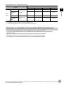
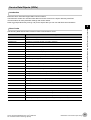
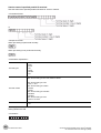
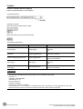
FH/FZ5 Manual Configuration
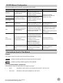
The following table gives the manual configuration of the FH/FZ5.
Cat. No.
Manual name
Contents
Main applications
Provides FH-series specifications,
FH Image Processing System dimensions, part names, I/O
information, mounting information,
Instruction Manual
and wiring information.
2285550-0
9524422-4
(FZ5-6/11) FH5 Image Processing
System Instruction Manual
9910002-2
(FZ5-L3)
Checking I/O and other
specifications and performing
Provides FH5-series specifications, installation and wiring
dimensions, part names, I/O
information, installation information,
and wiring information.
Z340
Describes the software functions,
Vision System FH/FZ5 Series
settings, and operations for using
User’s Manual
FH/FH5-series Vision Sensors.
Any application other than the
above applications and
communications
Z341
Describes the functions, settings,
Vision System FH/FZ5 Series
and operations of the processing
Processing Item Function
items that you can use with the FH/
Reference Manual
FH5-series Vision Sensors.
Checking information on
processing items when designing
or manipulating measurement
flows
Use this manual together with the
User’s Manual.
Z342
(This manual)
Describes the functions, settings,
and communications methods for
communicating between FH/FH5Vision System FH/FZ5 Series series Vision Sensors and external
devices (e.g., a PLC).
User’s Manual for
The following communications
Communications Settings
protocols are included.
Parallel, PLC Link, EtherNet/IP,
EtherCAT, and Non-procedure
Checking information on
communications functions
Z343
Describes the operating procedures
Vision System FH Series
Communicating with an NJ-series
for setting up and operating FH-series
Operation Manual for Sysmac
Controller via EtherCAT
Vision Sensors from the Sysmac
Studio
communications
Studio FH Tools.
Conventions Used in This Manual
Symbols
The symbols used in this manual have the following meanings.
IMPORTANT
Note
Indicates relevant operational precautions that must be followed.
Indicates operation-related suggestions from OMRON.
Use of Quotation Marks and Brackets
In this manual, menus and other items are indicated as follows.
[
“
]
”
Menu
Indicates the menu names or processing items shown in the menu bar.
Item name
Indicates the item names displayed on the screen.
Vision System FH/FZ5 Series User’s Manual
for Communications Settings (Z342)
1
2
Vision System FH/FZ5 Series User’s Manual
for Communications Settings (Z342)
Contents
FH/FZ5 Manual Configuration .............................................................................................................. 1
Conventions Used in This Manual ........................................................................................................ 1
1. Overview .........................................................................................................................................7
Introduction ................................................................................................................................................ 8
Confirming the System Configuration ........................................................................................................ 9
Basic Configuration for an FH/FZ5-series Vision System ..................................................................... 9
Communicating with an External Device ................................................................................................. 10
Basic Control Operations of the Sensor Controller ............................................................................. 10
Communications between the FH/FZ5 and an External Device ......................................................... 12
Controlling the FH/FZ5 ....................................................................................................................... 13
Communications Protocols for Communicating with the FH/FZ5 ....................................................... 15
Saving FH/FZ5 Data to an External Device ........................................................................................ 16
Control Methods Using an External Device ............................................................................................. 17
Control with Control Signals and Status Signals ................................................................................ 17
Command/Response Method ............................................................................................................. 21
Data Output after Measurements ....................................................................................................... 22
Setting Procedures for Communications ................................................................................................. 30
Communications Setup Procedures ................................................................................................... 30
Communications Protocols and Communications Modules ................................................................ 31
Differences in Specifications Based on the Communications Protocol .................................................... 32
List of Supported Signals by Communications Protocol ..................................................................... 32
Restrictions on Using Different Communications Modules Simultaneously ....................................... 33
Models That Are Compatible with the Communications Protocols ..................................................... 34
2. Methods for Connecting and Communicating with External Devices ....................................37
EtherCAT Connections (FH Only) ............................................................................................................ 38
Introduction to EtherCAT .................................................................................................................... 38
Structure of CAN Application Protocol over EtherCAT (CoE) ............................................................. 41
EtherCAT Slave Information Files (ESI Files) ..................................................................................... 42
Transitions of Communications States ............................................................................................... 43
Process Data Objects (PDOs) ............................................................................................................ 44
Service Data Objects (SDOs) ............................................................................................................. 47
Communications between an EtherCAT Master and Slaves .............................................................. 48
FH-series Vision Sensor Communications Method When Connected to EtherCAT ........................... 49
Communications Settings ................................................................................................................... 53
Communications Module Settings (Startup Settings) ......................................................................... 55
Communications Specifications Settings ............................................................................................ 56
Output Data Settings (Processing Item Registration) ......................................................................... 59
EtherCAT Network Configuration Settings ......................................................................................... 61
Communications Test ......................................................................................................................... 63
I/O Ports by Area (PDO Mapping) and Memory Assignments ............................................................ 63
I/O Signals .......................................................................................................................................... 68
Measurement Results That You Can Output with Fieldbus Data Output ........................................... 72
Measurement Trigger Input ................................................................................................................ 76
Command Response Processing ....................................................................................................... 77
Data Output ........................................................................................................................................ 80
Time Charts ........................................................................................................................................ 82
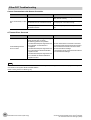
EtherCAT Troubleshooting ................................................................................................................. 86
Vision System FH/FZ5 Series User’s Manual
for Communications Settings (Z342)
3
Sysmac Error Status ........................................................................................................................... 87
Sysmac Device Features .................................................................................................................. 100
Object Dictionary .............................................................................................................................. 102
Communicating with PLC Link ............................................................................................................... 149
Communications Processing Flow .................................................................................................... 149
Communications Setup Procedures ................................................................................................. 151
Communications Module Settings (Startup Settings) ....................................................................... 151
Communications Specifications Settings .......................................................................................... 153
Output Data Settings (Processing Item Registration) ....................................................................... 168
Testing Communications .................................................................................................................. 173
Memory Allocation ............................................................................................................................ 176
I/O Signals ........................................................................................................................................ 179
Output Items ..................................................................................................................................... 181
Command List ................................................................................................................................... 183
Command Response Processing ..................................................................................................... 186
Data Output ...................................................................................................................................... 189
Time Charts ...................................................................................................................................... 192
PLC Link Troubleshooting ................................................................................................................ 195
Communicating with EtherNet/IP ........................................................................................................... 198
Introduction to EtherNet/IP ............................................................................................................... 198
Data Exchange with EtherNet/IP ...................................................................................................... 199
EtherNet/IP Communications ........................................................................................................... 202
Communications Processing Flow .................................................................................................... 203
Communications Setup Procedures ................................................................................................. 205
Communications Module Settings (Startup Settings) ....................................................................... 206
Communications Specifications Settings .......................................................................................... 207
Tag Data Link Setting Methods ........................................................................................................ 211
Output Data Settings (Processing Item Registration) ....................................................................... 214
Testing Communications .................................................................................................................. 218
Memory Allocation ............................................................................................................................ 220
I/O Signals ........................................................................................................................................ 227
Output Items ..................................................................................................................................... 230
Command List ................................................................................................................................... 231
Command Response Processing ..................................................................................................... 235
Data Output ...................................................................................................................................... 238
Time Charts ...................................................................................................................................... 240
Communicating with the Sensor Controller with EtherNet/IP Message Communications ................ 244
Command Setting Example .............................................................................................................. 247
EtherNet/IP Troubleshooting ............................................................................................................ 247
Non-procedure Communications ........................................................................................................... 249
Communications Processing Flow .................................................................................................... 249
Communications Setup Procedures ................................................................................................. 250
Communications Module Settings (Startup Settings) ....................................................................... 251
Communications Specifications Settings .......................................................................................... 252
Output Data Settings (Processing Item Registration) ....................................................................... 259
Testing Communications .................................................................................................................. 264
Output Items ..................................................................................................................................... 267
Command Formats ........................................................................................................................... 268
Command List ................................................................................................................................... 270
Output Format ................................................................................................................................... 274
Non-procedure Communications Troubleshooting ........................................................................... 276
Parallel Communications ....................................................................................................................... 277
4
Vision System FH/FZ5 Series User’s Manual
for Communications Settings (Z342)
Communications Processing Flow .................................................................................................... 277
Communications Setup Procedures ................................................................................................. 278
Communications Module Settings (Startup Settings) ....................................................................... 279
Communications Specifications Settings .......................................................................................... 280
Output Data Settings (Processing Item Registration) ....................................................................... 287
Testing Communications .................................................................................................................. 294
I/O Signals ........................................................................................................................................ 296
Output Items ..................................................................................................................................... 305
Command Formats ........................................................................................................................... 307
Time Charts ...................................................................................................................................... 310
Parallel Troubleshooting ................................................................................................................... 320
3. Appendices .................................................................................................................................321
Command Control .................................................................................................................................. 322
Parameter Notation Examples for Command Control ...................................................................... 322
Command List ................................................................................................................................... 326
Command Details ............................................................................................................................. 332
Non-procedure Command Details .................................................................................................... 391
Manual Revision History ........................................................................................................................ 476
Vision System FH/FZ5 Series User’s Manual
for Communications Settings (Z342)
5
6
Vision System FH/FZ5 Series User’s Manual
for Communications Settings (Z342)
1
Overview
Overview
This section provides a basic overview of the communications specifications and Sensor
Controller control methods. This information is required before performing
communications between the FH/FZ5 and an external device.
Introduction.......................................................................... 8
Confirming the System Configuration............................... 9
Communicating with an External Device ........................ 10
Control Methods Using an External Device .................... 17
Setting Procedures for Communications........................ 30
Differences in Specifications Based on the
Communications Protocol................................................ 32
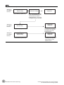
Introduction
This section provides a basic overview of the communications specifications and Sensor Controller control
methods. This information is required before performing communications between the FH/FZ5 and an external
device.
Confirming the System Configuration
(Refer to
Confirming the System Configuration (p.9))
The external device configuration that is required to perform measurement processing with the FH/FZ5 is described.
↓
Communicating with an External Device
The basic operations of the Sensor Controller, how the Sensor Controller works, and the specifications for
communications between the Sensor Controller and an external device are described. The following information is
provided.
Basic Flow of Communications and Signals (Refer to
Basic Control Operations of the Sensor Controller (p.10))
• Process from Starting Measurements at the Sensor Controller to Data Output (Reference: Communications between the
FH/FZ5 and an External Device (p.12))
• Sensor Controller Control Methods (Control Signals, Commands, etc.) (Refer to
Controlling the FH/FZ5 (p.13))
• Types of Communications Protocols for Communicating with the Sensor Controller (Refer to
Communications
Protocols for Communicating with the FH/FZ5 (p.15))
• Moving Data between the Sensor Controller and an External Device (Refer to
Saving FH/FZ5 Data to an External
Device (p.16))
↓
Control Methods Using an External Device
The methods that you can use to control the Sensor Controller from an external device are described.
Control with Control Signals and Status Signals (Refer to
Control with Control Signals and Status Signals (p.17))
Command/Response Method (Refer to
Command/Response Method (p.21))
Data Output after Measurements (Refer to
Data Output after Measurements (p.22))
↓
Setting Procedures for Communications
(Refer to
Setting Procedures for Communications (p.30))
The procedures that are required to set up communications before starting communications between the Sensor
Controller and an external device are given.
↓
Differences in Specifications Based on the
(Refer to
Communications Protocol
Communications Protocols and Communications Modules (p.31))
The differences in the specifications of the different communications protocols that you can use to communicate with the
Sensor Controller are described.
8
Introduction
Vision System FH/FZ5 Series User’s Manual
for Communications Settings (Z342)
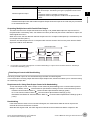
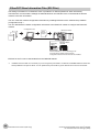
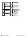
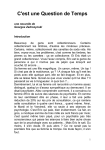
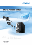
Confirming the System Configuration
The FH/FZ5 are Vision Systems that perform measurement processing through a Sensor Controller on
measurement objects that are imaged by a Camera.
A Vision System can be connected to a PLC, computer, or other external device and receive measurement
commands from or output measurement results to the external device.
1
Overview
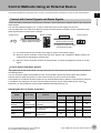
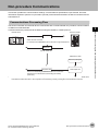
Basic Configuration for an FH/FZ5-series Vision System
External device (e.g, PLC)
FH/FZ5
The FH/FZ5 is connected to an external device (e.g., PLC) with a
Camera
communications cable and performs communications through one of
various communications protocols. Methods for Connecting and
Communicating with External Devices (p.37) for information on the A Camera and LCD Monitor (Box-type Monitor
different communications protocols.
only) for operation and monitoring are connected
in the FH/FZ5 Vision System. For details, refer to
the Instruction Manual that is provided with each
Communications cable
Communications protocol
individual device.
Parallel
Parallel I/O cable
PLC Link
Ethernet cable
RS-232C cable
EtherNet/IP
Ethernet cable
EtherCAT (FH only) Ethernet cable
Non-procedure
Ethernet cable
RS-232C cable
Vision System FH/FZ5 Series User’s Manual
for Communications Settings (Z342)
Confirming the System Configuration
9
Communicating with an External Device
This section gives the communications specifications, describes the control methods that you can use for
communications, and describes the settings that are required before starting communications with an external
device.
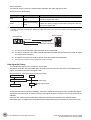
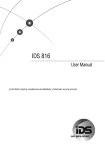
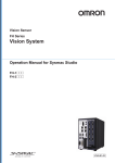
Basic Control Operations of the Sensor Controller
The following figure shows basic communications between an external device and the Sensor Controller and the
flow of signals and data.
Trigger sensor
Measurement triggers
and other control
commands are input.
PLC
Sensor Controller
The measurement
results are output.
• Status signals
• Overall judgement
• Measured values
• Character output
PLC
The following methods can be used to exchange data between an external device and the Sensor Controller.
Commands That Can Be Input to the Sensor Controller from an External Device
Type
Control
commands
Control signals
(input signals)
Description
A measurement is executed when a measurement trigger (i.e., an ON STEP signal) is input.
For information on control signals, refer to
Control with Control Signals and Status Signals
(p.17).
You can send commands to perform measurements, change scene groups, or perform other
Communications
tasks. The communications commands depend on the communications protocol that you
command input
use. Refer to the section for each communications protocol for details.
Data Output to an External Device from the Sensor Controller
Type
Status signals
Overall judgement
Measured values
10
Description
When the Sensor Controller confirms a control signal or communications command input and
begins measurement processing, the status of the Sensor is reported to the external device
through status signals (e.g., a BUSY signal).
For information on status signals, refer to
Control with Control Signals and Status Signals
(p.17).
NG is output whenever there is one or more NGs in the judgement results for multiple
processing items.*1
The overall judgement can be output through the OR signal or through the TJG output
parameter.
*1:
This behavior can be changed in the settings.
For information on the OR signal, refer to
Control with Control Signals and Status Signals
(p.17).
For information on the TJG output parameter.
The measured values from processing items can be output. The output items must be
processing items for output and registered as output data (data 0 to data 7). Refer to
Settings Required for Data Output (p.24) for details. You can also use commands to obtain
results after a measurement is performed.
Communicating with an External Device
Vision System FH/FZ5 Series User’s Manual
for Communications Settings (Z342)
Type
Character output (PLC Link
communications only)
Description
You can output character strings and numbers that are read by processing items such as
Character Inspection, Barcode, or 2DCode. Refer to
Items that Can Be Output as Output
Data (p.24) for details.
You can also use commands to obtain results after a measurement is performed.
1
Overview
Note
You can also use the FTP server to obtain logged image files and logged data files saved in the FH/FZ5 (or in external
memory) from a web browser or FTP client.
Vision System FH/FZ5 Series User’s Manual
for Communications Settings (Z342)
Communicating with an External Device
11
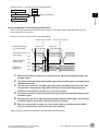
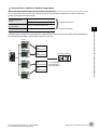
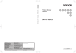
Communications between the FH/FZ5 and an External Device
Communications between the FH/FZ5 and an external device are performed as shown below.
The following figure shows the flow when a communications command is used to start a measurement and then
output data.
PLC or other external device
(1) Command
Example: Starting a
measurement, etc.
Data output request
(DSA signal)*1
Response
(3) Data
output
Sensor Controller
Measurement
flow
Communications processing
Communications
processing
Camera Input
Search
(2) The data at this
point is output to the
Communications
Module.
Output Unit
Communications
Module
An Output Unit processing item is required to
perform data output. (Multiple Output Unit items
can be used.)
Result Completion signal (GATE signal)*1
*1: When output control is set to [Handshaking]
(data output is controlled by the DSA and
GATE signals). Refer to
Control with
Control Signals and Status Signals (p.17).
(1) When the Sensor Controller receives a command from a PLC or other external device, it executes the
command and returns a response.
(2) The data obtained after the measurement is performed is output via the Communications Module by
the Output Unit (an abbreviation for Results Output Unit) processing item in the measurement flow.
(3) The measurement data is output when the Output Unit is executed, not when the measurement is
actually finished.(*1)
*1:
If handshaking is used for output control, the measurement data will remain in the Communications Module in a standby state
until a data output request (DSA signal) is received from an external device. Refer to
Data Output Control with Handshaking
(p.27).
IMPORTANT
To output data, you must place an Output Unit processing item in the measurement flow.
You can place multiple Output Unit processing items in the measurement flow. Refer to
Settings Required for
Data Output (p.24).
12
Communicating with an External Device
Vision System FH/FZ5 Series User’s Manual
for Communications Settings (Z342)
Controlling the FH/FZ5
There are three methods that you can use to control the Sensor Controller from a PLC or other external device.
They are described in this section.
For details on each control method, refer to their corresponding section.
1
Overview
Control Methods
Method
Overview
Trigger type or area
Signals or area used
Control signals and
status signals
Operation is controlled by the
ON/OFF status of the
ON/OFF status of the control
Measurement Trigger Signal
signals and status signals
(STEP) and Command Request
Bit (EXE).
Control with
commands and
responses
Control is performed by sending
control commands. The
execution results of the
command can be confirmed in
the response from the Sensor
Controller.
The control command code is
stored in the I/O memory of the PLC I/O memory (Command
PLC and then the Request Bit is Area and Response Area)
turned ON.
Data output after
measurements
After a measurement is
performed, the previously
specified measurement data is
output automatically.
Not required. (Output is
performed automatically after
measurement.)
1
Control with Control Signals and Status Signals (Refer to
Status Signals (p.17))
Control signals and status
signals
PLC I/O memory (Data Output
Area)
Control with Control Signals and
Control and status confirmation for the Sensor Controller is performed with the ON/OFF status of the
control and status signals.
This method is best suited for basic operations such as measurement triggers or to check the operating
status of the Sensor Controller.
Trigger sensor
Input signals
Output signals
External device
2
Command/Response Method (Refer to
Sensor Controller
Command/Response Method (p.21))
Control is performed by storing the control command and the response to that command in the I/O
memory of a PLC.
This method is best suited to send multiple commands to the Sensor Controller without using PLC
communications instructions.
Vision System FH/FZ5 Series User’s Manual
for Communications Settings (Z342)
Communicating with an External Device
13
Sensor Controller
External device
I/O memory
Command Area
Response Area
(1) Command
(3) Response
(2) Command
execution
Output Area
3
Data Output after Measurements (Refer to
Data Output after Measurements (p.22))
After a measurement is executed, the measurement data specified for output is automatically output to the
specified words in the I/O memory of the PLC.
This allows you to output measurement results from the Sensor Controller to the PLC automatically
without having to send data requests from the PLC.
Sensor Controller
External device
I/O memory
Command Area
Response Area
(2) Measurement data
Output Area
14
Communicating with an External Device
(1) Measurement processing
Vision System FH/FZ5 Series User’s Manual
for Communications Settings (Z342)
Communications Protocols for Communicating with the FH/FZ5
The FH/FZ5 can be controlled from a PLC, computer, or other external device through a variety of
communications protocols.
The communications protocols that can be used to control the FH/FZ5 from an external device are described in
this section.
Overview
PLC
1
Sensor Controller
Computer
Control can be performed through different communications protocols.
Parallel
EtherNet/IP
PLC Link
EtherCAT
Non-procedure
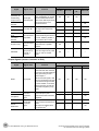
Applicable Communications Protocols
OK: Supported, ---: Not supported.
Communications
method
Contact
inputs
Overview
Parallel
I/O
Parallel
Data is exchanged between an external device and the
Sensor Controller through combinations of ON/OFF
signals from multiple physical contacts.
PLC Link
OK
Ethernet
RS-232C/
422
---
---
This is OMRON’s communications protocol for Vision
System.
The control signals, Command Area/Response Area, and
--area to store measurement data are assigned in the I/O
memory of the PLC, and data is exchanged cyclically to
share data between the PLC and the Vision System.
OK
OK
This is an open communications protocol.
Tag data links are used to communicate with the FH.
On the PLC, structure variables are created that
correspond to the control signals, command/response
EtherNet/IP
--data, and measurement data. These variables are then
used as tags to input and output data through tag data
links to exchange data between the PLC and the Sensor
Controller.*1
OK
---
EtherCAT
(FH only)
This is an open communications protocol.
PDO (process data object) communications are used to
communicate with the Sensor Controller.
I/O ports that correspond to the control signals,
--command/response data, and measurement data are
prepared in advance, and the variables assigned to those
I/O ports are used to input and output data via PDO
communications to exchange data between the PLC and
the Sensor Controller.
OK
---
Frame
Nontransmission procedure
Command frames are sent to the Sensor Controller and
response frames are received from the Sensor Controller
without the use of any specific protocol.
--Data can be exchanged between the PLC, computer, or
other external device and the Sensor Controller by
sending and receiving ASCII or binary format data.
OK
OK
Data
sharing
*1:
Communications cable type
Communications
protocol
When connected to a CJ-series PLC, specify the areas in the I/O memory.
Vision System FH/FZ5 Series User’s Manual
for Communications Settings (Z342)
Communicating with an External Device
15
Saving FH/FZ5 Data to an External Device
In addition to sending and receiving data through communications protocols, the FH/FZ5 can also exchange
data with an external device using the method that is described in this section.
For details, refer to the
Vision System FH/FZ5 Series User's Manual (Cat. No. Z340).
Connecting the FH/FZ5 as an External Drive
The FH/FZ5 can directly save setting data, logged data, scene groups, and other data to the following
external media in addition to its own built-in RAM disk.
• External Memory (Refer to
Using External Memory Devices in the Vision System FH/FZ5 Series User's Manual
(Cat. No. Z340).)
Data can be saved directly to a USB memory stick or SD Memory Card inserted into the slot on the FH/FZ5.
• Network Drive (Refer to
Shared folder on a computer connected to the network in the Vision System FH/FZ5 Series
User's Manual (Cat. No. Z340).
You can save data directly to a shared folder on a computer connected via Ethernet.
Computer
Sensor Controller
Ethernet
Saved directly.
Shared computer folder (the
shared folder settings must
be set on the computer)
The Sensor Controller is set
up to save to the shared
folder on the computer.
• Logged images
• Logged data
• Data Transfer (FTP Server) (Refer to
Saving Data to an External Device in the Vision System FH/FZ5 Series User's
Manual (Cat. No. Z340).
You can move data, such as logged image data, that was saved to USB memory or the RAM disk in the Sensor
Controller to a computer via Ethernet.
The computer must provide FTP client to access the FH/FZ5.
The FH/FZ5 cannot access the computer itself
Computer
Sensor Controller (FTP server)
Ethernet
Browser
(FTP client)
RAM disk
Image files
Access via FTP
Images files moved to the computer.
This enables you to move logged images off of the Sensor Controller’s RAM disk before it becomes full.
• Remote Operation over a Network (Refer to
Remotely Operating the Controller (Remote Operation) in the Vision
System FH/FZ5 Series User's Manual (Cat. No. Z340).)
If more than one FH Sensor is connected together via Ethernet, a computer (i.e., the FH/FZ5 Tool) connected to that
same Ethernet network can be used to operate and monitor all of the connected FH Sensors.
Computer (FH/FZ5 software)
You can adjust images and perform
monitoring for all Sensors connected
on the network.
Ethernet
Sensor
Controller
16
Sensor
Controller
Hub
Sensor
Controller
Communicating with an External Device
Vision System FH/FZ5 Series User’s Manual
for Communications Settings (Z342)
Control Methods Using an External Device
This section describes the methods that you can use to control the Sensor Controller from a PLC or other external device.
1
Overview
Control with Control Signals and Status Signals
Control and status confirmation for the Sensor Controller is performed with the ON/OFF status of the control and
status signals.
You can send operation triggers (e.g., to start a measurement) as control signals from the PLC.
The operating status of the Sensor, judgement results, and other status information can be confirmed through
status signals sent from the Sensor Controller.
Trigger sensor
Sensor Controller
Control signals
External device
Status signals
(2) Command received
(BUSY signal turned ON).
(1) Input a measurement trigger.
(STEP signal turned ON.)
(3) Judgement results are output
(OR signal turned ON).
(1) The external device turns ON the STEP signal to input a measurement trigger.
(2) When the Sensor Controller confirms that the STEP signal is ON, it outputs the BUSY signal to the
external device and begins a measurement.
(3) When the Sensor Controller finishes the measurement, it outputs the judgement results on the OR
signal.
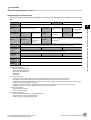
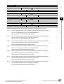
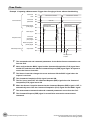
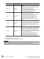
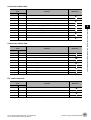
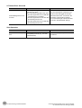
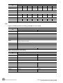
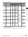
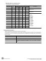
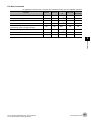
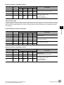
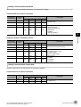
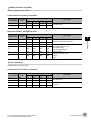
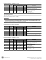
Control Signals and Status Signals
The signals that the Sensor Controller can input and output as control signals and status signals are described in
the following tables.
You can see which signals are available for each communications protocol by looking down the individual
protocol columns under the Signals for each communications protocol column in the tables.
These tables do not indicate whether signals can be used simultaneously by different communications protocols.
For details on the restrictions on which communications protocols can be used simultaneously, refer to
Restrictions on Using Different Communications Modules Simultaneously (p.33).
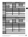
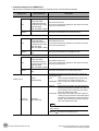
Input Signals (PLC to Sensor Controller)
Signals for each communications protocol
Signal
EXE
Command
Request
TRIG
Trigger
STEP
Signal name
Function
Turn ON this signal (from the
Control
PLC) to send a command to
Command
Execution Signal the FH/FZ5.
Measure Bit
Turn ON this signal to execute
measurements.
Measure Bit
Turn ON this signal to execute
measurements.
Vision System FH/FZ5 Series User’s Manual
for Communications Settings (Z342)
Parallel
PLC Link
EtherNet/
IP
EtherCAT
---
OK
OK
---
---
---
---
OK
---
---
OK
---
---
---
---
OK
OK
---
---
---
Control Methods Using an External Device
17
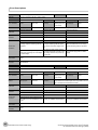
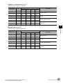
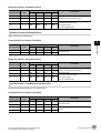
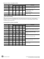
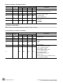
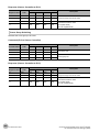
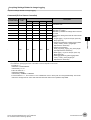
Signals for each communications protocol
Signal
DSA
(Used only for
handshaking
output control.)
Signal name
Data Output
Request Signal
Result Set
Request
ERCLR
Error Clear
XEXE
Flow
Command
Request
Error Clear Bit
Function
Use this signal (from the PLC)
during handshaking to request
from the FH/FZ5 the external
output of the data output results
from the execution of the
measurement flow.
Turn ON this signal to clear the
ERR signal from the Sensor
Controller.
Turn ON this signal to execute
Flow Command a command during execution of
PLC Link, fieldbus, parallel, or
Request Bit
non-procedure flow control.
Parallel
PLC Link
EtherNet/
IP
EtherCAT
OK
OK
OK
---
---
---
---
OK
---
---
OK
---
---
---
---
OK
---
OK
OK
---
---
---
---
OK
DI (DI0 to DI7)
These signals are used to input
Command Input
commands from a parallel
Signals
interface.
OK
---
---
---
ENCTRIG
Encoder Trigger
Input (Phase A,
Phase B, or
Phase Z)
This is the encoder input
signal. This signal is only used
when you use an encoder
trigger.
OK
---
---
---
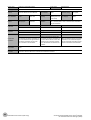
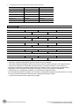
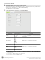
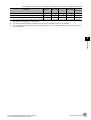
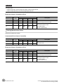
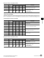
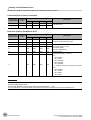
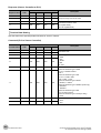
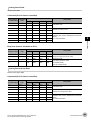
Output Signals (Sensor Controller to PLC)
Signal
Signal name
Signals for each communications protocol
Parallel
PLC Link
EtherNet/IP EtherCAT
OK
OK
OK
OK
BUSY
Busy Signal
This signal tells when new
commands and other external
inputs cannot be acknowledged
during processing of other
external inputs.*1
Just because this signal is ON
does not necessarily mean that
a command is being executed.
To check whether a command
is being executed, access the
Command Completion (FLG)
signal.
FLG
Control
Command
Completion
Signal
The FH/FZ5 uses this signal to
tell the user (PLC) that
command execution has been
completed.
---
OK
OK
---
---
---
---
OK
OK
OK*3
OK
---
Data Output
Completion
Signal
This signal tells the user (PLC)
when to read the measurement
results.
Data output is enabled when
this signal is ON.*2
---
---
---
OK
Command
Completion
GATE
Result
Notification
18
Function
Control Methods Using an External Device
Vision System FH/FZ5 Series User’s Manual
for Communications Settings (Z342)
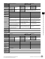
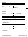
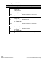
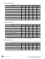
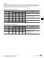
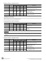
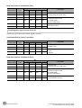
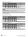
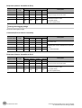
Signal
Signal name
Function
Overall
Judgment
Overall
Judgement
Output Signal
This signal gives the results of
the overall judgement.*5
DO (DO0 to
DO15)
Data Output
Signals
These signals are used to
output parallel data and parallel
judgements through a parallel
interface.
XFLG
This signal tells when
execution of a command that
Flow Command
was executed during execution
Completion Bit
of PLC Link or fieldbus flow
control has been completed.
Trigger Ready
OR
Flow
Command
Completion
XBUSY
Flow
Command
Busy
This signal tells when a
command that was input during
Measurement
Command Busy execution of PLC Link or
fieldbus flow control is being
Bit
executed.
Measurement
Command Wait
Bit
This signal tells when input of a
command can be
acknowledged during
execution of PLC Link or
fieldbus flow control.
Trigger ACK
TRIG Signal
Acknowledged
Bit
The FH/FZ5 uses this signal to
acknowledge reception of a
TRIG signal.
Command
Ready
Command
This signal tells when control
Execution Ready
command can be executed.
Bit
XWAIT
Flow
Command
Wait
Vision System FH/FZ5 Series User’s Manual
for Communications Settings (Z342)
Parallel
PLC Link
OK
---
EtherNet/IP EtherCAT
---
---
1
---
---
---
OK
OK
---
OK
---
---
---
---
OK
OK
---
---
---
---
OK
OK
---
---
---
---
OK
---
OK
OK
---
---
---
---
OK
---
OK
OK
---
---
---
---
OK
---
---
---
OK
---
---
---
OK
Control Methods Using an External Device
Overview
Camera Image
Input Enabled
Signal
This signal tells when the
STEP (Measurement Trigger)
signal can be input.*4
When using multiple inputs, the
next STEP signal is accepted
only after this signal turns ON.
READY
Signals for each communications protocol
19
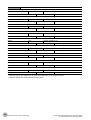
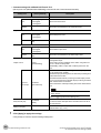
Signal
Signal name
ERR
Error Status
Function
The FH/FZ5 provides
notification with this signal
when it detects the following
errors.
Refer to
Error Messages
and Troubleshooting in the
Vision System FH/FZ5 Series
User's Manual (Cat. No. Z340).
Error Signal
• System error
• Communica• Camera
tions timeout
connection
• STEP input
error
during
• Battery error
measureme
• Fan error
nt
Signals for each communications protocol
Parallel
PLC Link
EtherNet/IP EtherCAT
OK
---
OK
---
---
---
---
OK
OK
---
OK
---
---
---
---
OK
The ERR signal does not turn
OFF even after the error is
eliminated. The signal turns
OFF only when the error status
is cleared by a control
command.
RUN
Run Mode
*1:
*2:
*3:
*4:
*5:
20
Measurement
Mode Signal
The FH/FZ5 turns ON this
signal when measurements
can be performed and it is in
Run Mode.
ACK
This signal tells when
Command
execution of the DI command
Completion Flag
has been completed.
OK
---
---
---
SHTOUT
Exposure
Completion
Signal
This signal tells when Camera
exposure has been completed.
OK
---
---
OK
STGOUT
Strobe Trigger
Output
This is the trigger signal for the
strobe.
OK
---
---
---
The execution of commands or other processing received through any other protocol cannot be detected.
The parallel BUSY signal can be used in all protocols.
If you use more than one protocol and need to detect command execution, use the parallel communications BUSY signal.
This signal is linked to the Output Unit processing items in the measurement flow.
It is not associated with the BUSY signal. It is not related to the parallel interface OR signal.
Data is not output when there is no handshaking for the PLC Link protocol.
This signal is always OFF during display of a through image.
The OR signal is output only when the [Output] option is selected in the Adjustment Window.
Control Methods Using an External Device
Vision System FH/FZ5 Series User’s Manual
for Communications Settings (Z342)
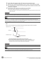
Command/Response Method
Parallel
1
Overview
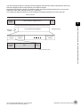
Commands are input to the Sensor Controller by turning the DI signals (DI0 through DI7) ON and OFF. There
is no direct response to these commands. Confirm whether a command was received by checking the BUSY
signal.
The command code is input with signals DI0 through DI6, and the command is executed by turning ON DI7.
DI7 DI6 DI5 DI4 DI3 DI2 DI1 DI0
Execution Command
Command information
PLC Link, EtherNet/IP, or EtherCAT
Command/response control signals can be exchanged by storing control commands from the PLC to the
Sensor Controller and responses from the Sensor Controller to the PLC in the I/O memory of the PLC. This
enables you to send single measurement and scene switch requests to the Sensor Controller without any
sequence control with communications commands from the PLC.
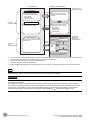
Memory Areas Used by the Command/Response Control Method
Command Area
You write the control commands to execute for the Sensor Controller to this area.
Response Area
You read the results of executing the control commands that were written to the Command Area
from this area.
PLC
CPU Unit
Sensor Controller
I/O memory
(communications areas)
(1) Command Area
(5) Response Area
(2) Command
• Switch Scene
• Single Measurement, etc.
(4) Response
OK, etc.
(3) Command is processed.
Flow of Communications between the PLC and the Sensor Controller
(1) The PLC (the user) writes a control command to a specified PLC I/O memory area (the Command
Area).
(2) The PLC (the user) then turns ON the EXE bit to send the control command to the Sensor Controller.
(3) The Sensor Controller executes the received control command.
(4) The Sensor Controller returns a response to the PLC after the control command is executed.
(5) The PLC (the user) stores the response in a specified PLC I/O memory area (the Response Area).
The available control commands depend on the communications protocol that is used.
Refer to the
Command List (p.326).
Note
With EtherNet/IP tag data link communications, you cannot output character strings with commands. If you want to output
character strings, send the commands through message communications.
Vision System FH/FZ5 Series User’s Manual
for Communications Settings (Z342)
Control Methods Using an External Device
21
Non-procedure Communications
Communications commands are sent to the Sensor Controller through sequence control in the PLC. An
external device and the Sensor Controller communicate through non-procedure (normal) communications.
Data Output after Measurements
After a Single Measurement or Start Continuous Measurements command is executed, the Sensor Controller
automatically outputs the data that corresponds to the measurements that have been specified as output items
to the PLC. This allows you to easily pass measurement results data from the processing items to the PLC. You
can also choose to output only when the PLC meets the conditions that are required to receive the data (i.e.,
when handshaking is turned ON).
The output destination for data depends on the protocol that is used to communicate between the external
device and the Sensor Controller, as described below.
PLC Link, EtherNet/IP, or EtherCAT
The output data is automatically output to the following area that is specified PLC I/O memory.
Area of Memory Used for Data Output after Measurement
Data Output Area
The output data for the measurement is written to this area by the Sensor Controller after execution
of the measurement.
PLC
CPU Unit
(1)
I/O memory
(communications areas)
Data
Output Area
Measurement
execution
Sensor Controller
(2) Data
• Specified data is automatically output.
• Output characters
Flow of Communications between the PLC and the Sensor Controller
The data to output after measurement and the PLC I/O memory area (Data Output Area) to store that data
are specified in advance. (Reference: Settings Required for Data Output (p.24).)
(1) Measurement is executed.
(2) After a measurement is executed, the specified measurement data is stored in the Data Output Area
in the PLC.
Parallel
The output data is output to the PLC signal wires via the DO signals (DO0 to DO15).
Non-procedure Communications
The output data is output to the PLC reception buffer through non-procedure (normal) communications.
22
Control Methods Using an External Device
Vision System FH/FZ5 Series User’s Manual
for Communications Settings (Z342)
Outputting the Output Data
The measurement data is output to the external device via the Communications Module by the Data Output
processing unit located in the measurement flow.
Therefore, to output measurement data, you must place an Output Unit processing unit in the measurement flow.
The measurement data is output when the Output Unit is executed, not when the measurement is actually
finished.
1
Overview
Sensor Controller
Processing
order
Single Measurement
command
Measurement flow
Measurement started.
0.Camera Image Input
Measurement executed.
1.Search
Search measurement
results output.
2.Data Output
Processing started
(BUSY).
Communications
Module
The results for
measurements for
1. Search are output.
You can output character strings that were read by processing items that read characters, such as Character
Inspection or Barcode. (You must use PLC Link communications to do this.)
Character strings are output simultaneously when the processing item is executed.
Sensor Controller
Processing
order
Single Measurement
command
Measurement flow
Measurement started.
0.Camera Image Input
Processing started
(BUSY).
Measurement processed.
1.Character Inspection
Communications
Module
Read characters are output.
Characters are output
at the same time that
the characters are read.
Vision System FH/FZ5 Series User’s Manual
for Communications Settings (Z342)
Control Methods Using an External Device
23
Items that Can Be Output as Output Data
Measurement Data
You can output up to eight items (32 bytes) with one Output Unit processing unit.
Note
• If you need to output nine or more data items, set more than one Output Unit processing unit in the measurement
flow.
Refer to
Outputting Multiple Measurement Data Items (p.25).
• The number of data items that can be output by one Output Unit processing unit can be increased by changing a
setting when using PLC Link or EtherCAT communications, as described below.
• PLC Link: 256 max. (1,024 bytes max.)
• EtherCAT: 64 max. (256 bytes max.)
The following items can be output:
•
•
•
•
Judgement result
Measured parameters (correlation values, reference coordinates, etc.)
Results calculated based on the values of the measured parameters
Judgement results from expression results (Parallel Judgement Output)
Character Output (PLC Link Communications or Non-procedure Communications Only)
You can output the characters that were read by processing items such as Character Inspection.
• Character output is supported only for PLC Link communications or non-procedure communications.
• A maximum of 32 characters can be output.
• Read character strings are output separated by delimiters or non-procedure communications.
The processing items that support character output are listed below.
Refer to the descriptions for each processing item for details on the character output format.
• Character Inspection (Refer to
Character Inspection in the Vision System FH/FZ5 Series Processing Items
Reference Manual (Cat. No. Z341).)
• Barcode (Refer to
Barcode in the Vision System FH/FZ5 Series Processing Items Reference Manual (Cat. No.
Z341).)
• 2DCode (Refer to
2DCode in the Vision System FH/FZ5 Series Processing Items Reference Manual (Cat. No.
Z341).)
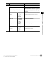
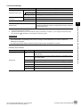
Settings Required for Data Output
Use the following procedure to set up Output Unit processing units for data output.
Measurement Data
1
Place the output data in the processing flow.
Place the processing unit for data output in the measurement flow.
Processing Units That Serve as Output Units
The processing items under [Output result] in the processing item tree in the Flow Editor serve as Output
Units.
24
Control Methods Using an External Device
Vision System FH/FZ5 Series User’s Manual
for Communications Settings (Z342)
1
Overview
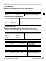
Output Unit Selection
Select the Output Units according to the communications protocol based on the combinations that are
shown in the following table.
For details on communications protocols, refer to
Communications Protocols for Communicating with
the FH/FZ5 (p.15).
OK: Data can be output, ---: Data cannot be output.
Communications protocol
Output unit
2
Parallel
PLC Link
EtherNet/IP
EtherCAT
Nonprocedure
Parallel Data Output
OK
---
---
---
---
Parallel Judgement Output
OK
---
---
---
---
Data Output
---
OK
---
---
OK
Fieldbus Data Output
---
---
OK
OK
---
Set the items to output.
Set the items to output as output data in the Output Units that you have placed in the measurement flow.
Refer to the descriptions for the communications protocol for the specific procedures to set the output
items in the Output Units.
Character Output (PLC Link Non-procedure Communications Only)
Set the character output settings for processing items that read output characters, such as Character
Inspection.
The character output operation is executed by the above processing items. In this case, it is not necessary to
set an Output Unit in the measurement flow.
Refer to the descriptions for individual processing items for details on the settings required for character
output.
Character Inspection (Refer to
Character Inspection in the Vision System FH/FZ5 Series Processing
Items Reference Manual (Cat. No. Z341).)
Barcode (Refer to
Barcode in the Vision System FH/FZ5 Series Processing Items Reference Manual
(Cat. No. Z341).)
2DCode (Refer to
2DCode in the Vision System FH/FZ5 Series Processing Items Reference Manual
(Cat. No. Z341).)
Outputting Multiple Measurement Data Items
Using Multiple Output Units for Data Output
You can register more than one Output Unit in the measurement flow.
If you want to output different types of data during measurement flow processing, or if you want to output
more than nine different data items, you must register multiple Output Units in the measurement flow.
Data output is executed for each Output Unit set in the measurement flow, but the output destination for that
Vision System FH/FZ5 Series User’s Manual
for Communications Settings (Z342)
Control Methods Using an External Device
25
data is the same PLC I/O memory area (the Data Output Area).
In this case, the output data that is output first will be overwritten by any output data written afterwards. Use
one of the following methods if you want to save all the output data.
Sensor Controller
Processing
order
Measurement started.
PLC
Measurement flow
0.Camera Image Input
I/O memory
1.Search
Command
Area
Search measurement
results output.
2.Data Output
Response
Area
3.Position Compensation
Position compensation values output.
Communications
Module
Output Area
The data that is output
first is overwritten by the
second data output
4.Data Output
Offsets (PLC Link Communications Only)
When you use multiple Output Units to output data, you can offset the write destination of the output data
for each Output Unit.
Set the [Offset] for the Data Output processing item. Refer to
Output Data Settings (Processing Item
Registration) (p.214).
Controlling Data Output with Handshaking
If handshaking is used to control data output, the timing of outputting the data is controlled by I/O signals.
Each time that data is output, read the output data and move it to a different part of I/O memory in the
PLC.
Refer to
Data Output Control with Handshaking (p.27).
Note
For ASCII data output through non-procedure communications, you can append a record separator after each output
data item. (The default is the delimiter.)
The following two types of data can be output via parallel communications:
Output unit
Parallel Data Output
26
Control Methods Using an External Device
Output data
The measurement data is output. A maximum of eight items can be output.
Vision System FH/FZ5 Series User’s Manual
for Communications Settings (Z342)
Output unit
Output data
The judgement results are output. A maximum of 16 judgement result
items can be output. The following two types of judgement results can be
output:
• Judgement results for specified processing items
• Judgement results of set judgement conditions for the specified item
values
Parallel Judgement Output
1
Overview
Parallel Data Output Units and Parallel Judgment Output Units are output in the order they are processed
in the measurement flow.
Outputting Multiple Items with Parallel Data Output
The items that are set for output data numbers 0 through 7 via parallel data output are output to the PLC
reception buffer in ascending order, one data item at a time (16-bit units). Each time a data item is output, the
GATE signal turns ON.*1
When this occurs, the first data item that was output to the PLC reception buffer (data 0) is overwritten by the
next output data item (data 1).
Therefore, the data output to the PLC reception buffer must be saved to PLC memory each time the GATE
signal turns ON for each data item.
Data output order
Parallel data output
*1:
PLC
16 bits
0㧚Measurement data 0
D0 to D15
signals
7㧚Measurement data 7
GATE
signal
Measurement
data 0
Measurement
ata 7
Reception
buffer
ON
OFF
The operation of the DSA signal depends on whether handshaking for output control is enabled. Reference: Data Output
Control with Handshaking (p.27).
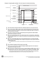
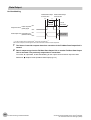
Data Output Control with Handshaking
The timing for data output can be controlled through the DSA and GATE signals.
This is useful when receiving output data from multiple Output Units, because it enables you to control the timing
for transferring output data.
Requirements for Using Data Output Control with Handshaking
To use data output control, set the output control method to [Handshaking] in the communications protocol
settings. For details, refer to
Communications Specifications Settings for each communications protocol.
Parallel Communications: Refer to
Communications Specifications Settings (p.280).
PLC Link Communications: Refer to
Communications Specifications Settings (p.153).
EtherNet/IP and EtherCAT Communications: Refer to Communications Specifications Settings (p.56 or
p.207).
Handshaking
If the external device does not turn ON the DSA signal, the measurement data will not be output to the
external device from the Sensor Controller.
While the DSA signal is ON, the GATE signal turns ON when the measurement data is output from the
Vision System FH/FZ5 Series User’s Manual
for Communications Settings (Z342)
Control Methods Using an External Device
27
Sensor Controller.
The external device receives the measurement data when the GATE signal turns ON.
Signals Used for Handshaking
Signal
*1:
Name
Operation
DSA
Data Output Request
Signal
This signal is sent from the external device (PLC) to the Sensor
Controller to request data output.
GATE
This signal is sent by the Sensor Controller to the external device (PLC)
Data Output Completion
to tell the PLC when to receive the output data. This signal is sent only
Signal
while the DSA signal is ON.*1
If handshaking is not enabled for output control, the GATE signal will also be turned ON when data is output from the Sensor
Controller. However, if handshaking is disabled for output control during PLC Link communications, the GATE signal is not
even output.
Sensor Controller
External device
(1) DSA signal
(2) GATE signal
(3) Measurement results output
(1) The PLC turns ON the DSA signal and waits for the output data.
(2) The Sensor Controller turns ON the GATE signal when the DSA signal is ON and it is ready to output
the measurement results(*1).
(3) The Sensor Controller turns ON the GATE signal and outputs the output data.
*1:
This is when an Output Unit in the measurement flow is executed.
DSA Signal ON Timing
Turn ON the DSA signal when you want to receive data.
The Sensor Controller will output data when an Output Unit has been executed, there is data waiting to be
output, and it detects that the DSA signal is ON.
Measurement flow
DSA (data output request) signal status
Start measurement.
OFF
Processing items related to results output
Processing item
No data output.
ON
Data output started.
To output measurement results immediately, execute the measurement trigger and turn ON the DSA signal.
The Sensor Controller does not monitor when the DSA signal changes from OFF to ON. It only checks for the
ON state.
Therefore, the measurement results will be output from the Sensor Controller to the external device
immediately after an Output Unit is executed and the output data must be received by the PLC at this time.
28
Control Methods Using an External Device
Vision System FH/FZ5 Series User’s Manual
for Communications Settings (Z342)
Measurement flow
DSA (data output request) signal status
OFF
Start measurement.
ON
1
Data output started.
Processing items related to results output
Overview
Processing completed.
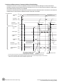
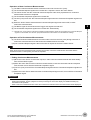
Receiving Multiple Continuous Output Data Items
When receiving multiple output data items from multiple Output Units, use the DSA and GATE signals to
receive the items one at a time.
Example: PLC Link Communications with Handshaking
Output Unit 1 executed.
Measurement trigger
(e.g., STEP signal)
Data Output Request
(DSA) signal
Result Completion
(GATE) signal
Output data
(DATA 0 to 7)
Wait for the
first output data.
2
3
4
5
6
Wait for the
second output data.
ON
OFF
ON
OFF
ON
First
output data
OFF
(1)
1
Output Unit 2 executed.
(2) (3) (4) (5)
Second output data
(6)
When the first data is received, the user (PLC) turns ON the measurement trigger and
the DSA signal.
The Sensor Controller turns ON the GATE signal when the DSA signal is turned ON and
outputs the first data.
The user (PLC) turns OFF the DSA signal again when the GATE signal turns ON. Then,
the user (PLC) confirms the output data received in the PLC Data Output Area and
moves the received data to another area in PLC I/O memory.
The Sensor Controller confirms that the DSA signal is OFF and automatically turns OFF
the GATE signal.
The user (PLC) then turns ON the DSA signal again after the output data is received and
the GATE signal is turned OFF, and waits for the second data.
When the second data is output, the second data output is received when the GATE
signal is turned ON and steps 3 and 5 above are repeated.
Steps 3 through 5 above are repeated for all subsequent data output items.
Vision System FH/FZ5 Series User’s Manual
for Communications Settings (Z342)
Control Methods Using an External Device
29
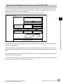
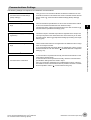
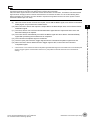
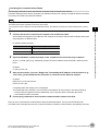
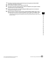
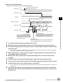
Setting Procedures for Communications
Communications Setup Procedures
Perform the following settings.
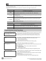
1. Setting the Communications Module.
(Startup settings)
· · · The type of the Communications Module is selected to determine the
communications method to use between the Sensor Controller and the
external device. For details, refer to
Communications Module Settings
(Startup Settings) under Methods for Connecting and Communicating with
External Devices for each communications protocol.
↓
2. Setting communications specifications. · · · The communications specifications are set for the communications method
of the Communications Module that was selected in step 1.
Set the communications area assignments for exchanging data with the
external device. For details, refer to
Communications Specifications
Settings under Methods for Connecting and Communicating with External
Devices for each communications protocol.
*1:
The settings (including communications settings) can be saved and loaded
as system data (.ini file extension) or system + scene group 0 data (.bkd file
extension) files.
Refer to
Saving Settings Data to the Controller RAM Disk or an External
Memory Device in the Vision System FH/FZ5 Series User's Manual (Cat.
No. Z340).
↓
3. Setting output data.
*1:
···
When performing control through data
sharing (data output after
measurement).
The data to output to the Data Output Area is registered in the Output Unit.
The result output is placed in the processing flow in the same way as for
other processing items.
↓
4. Testing communications.
30
· · · If communications are not working properly, check the communications
setup from step 2 and perform a communications test to determine if the
Sensor Controller can be detected on the network.
If that does not solve the problem, refer to the troubleshooting section.
Setting Procedures for Communications
Vision System FH/FZ5 Series User’s Manual
for Communications Settings (Z342)
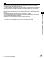
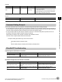
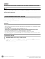
Communications Protocols and Communications Modules
A Communications Module is used to communicate between the Sensor Controller and an external device.
The appropriate Communications Module must be set for the communications protocol that is used to
communicate between the Sensor Controller and the external device.
1
Overview
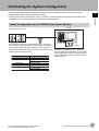
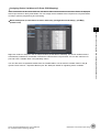
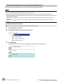
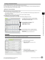
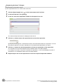
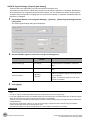
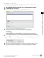
Communications Module Settings
The Communications Module to use for communications is selected in the startup settings.
1
2
On the Main Window, select [Tool] − [System Settings] to open the system settings.
Select [System setting] − [Startup] − [Startup setting] on the Multiview Explorer on the left and
then click the [Communication] tab.
For detailed setting procedures, refer to
protocol.
Communications Module Settings for each communications
IMPORTANT
After you select the Communications Module to use, save the settings to the Sensor Controller and restart the Sensor
Controller.
The selected Communications Module will be enabled after the Sensor Controller restarts. You can then set up the
communications.
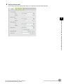
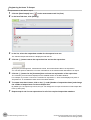
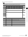
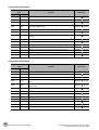
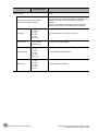
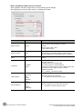
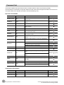
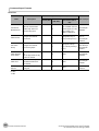
Selecting a Communications Module
Select a Communications Module based on the communications protocol to use to communicate between
the Sensor Controller and external device and the connected communications interface, as shown in the
following table.
Communications
protocol
Parallel
Communications
interface
Parallel
Communications Module
Standard Parallel I/O
Serial (Ethernet)
Ethernet
PLC Link
PLC Link (SYSMAC CS/CJ/CP/One)
PLC Link (MELSEC QnU/Q/QnAS)
PLC Link (JEPMC MP)
Serial (RS-232C/422)
RS-232C/422
EtherNet/IP
EtherNet/IP
EtherCAT
EtherCAT
PLC Link (SYSMAC CS/CJ/CP/One)
PLC Link (MELSEC QnU/Q/QnAS)
Fieldbus
EtherNet/IP
EtherCAT
Serial (Ethernet)
Ethernet
Non-procedure
Normal (UDP)
Normal (TCP)
Normal (TCP Client)
Normal (UDP) (Fxxx series method)
Serial (RS-232C/422)
RS-232C/422
Vision System FH/FZ5 Series User’s Manual
for Communications Settings (Z342)
Normal
Normal (Fxxx series method)
Setting Procedures for Communications
31
Differences in Specifications Based on the Communications Protocol
List of Supported Signals by Communications Protocol
Some of the control signals and output signals that can be used depend on the communications protocol as
shown below.
IMPORTANT
The control signals and status signals cannot be used for control in non-procedure communications.
OK: Signal can be used, ---: Signal cannot be used.
Communications protocol
Signal
STEP
TRIG
Measure Bit
Trigger
Control
signals
ERCLR
Error Clear
DSA
Result
Set Request
BUSY
READY
Trigger Ready
OR
Overall
judgment
One-shot OR *3
Status
signals
RUN
Run Mode
GATE
Result
Notification
ERR
Error Status
Error Clear Bit
Data Output
Request Bit
Command Busy
Bit
Camera Image
Input Enabled
Signal
Overall
Judgement
One-shot Overall
Judgement
Result Signal
Measurement
Mode Signal
Data Output
Completion Bit
Error Bit
XFLG
Flow
Command
Completion
32
Flow Command
Completion Bit
Parallel
PLC Link
EtherNet/IP
EtherCAT
OK
---
---
---
---
---
OK
---
---
---
---
OK
---
OK
OK
---
---
---
---
OK
OK
OK
OK
---
---
---
---
OK
OK
OK*1
OK*1
OK*1
OK
---
---
---
---
---
---
OK
OK
---*2
OK
---
---
---
---
OK
OK
---
---
---
OK
OK
OK
---
---
---
---
OK
OK
OK
OK
---
---
---
---
OK
OK
OK
OK
---
---
---
---
OK
---
OK
OK
---
---
---
---
OK
Differences in Specifications Based on the Communications Protocol
Vision System FH/FZ5 Series User’s Manual
for Communications Settings (Z342)
OK: Signal can be used, ---: Signal cannot be used.
Communications protocol
Signal
XBUSY
XWAIT
Flow
Command
Wait
*1:
*2:
*3:
Flow Command
Wait Bit
PLC Link
EtherNet/IP
EtherCAT
---
OK
OK
---
---
---
---
OK
---
OK
OK
---
---
---
---
OK
1
Overview
Status
signals
Flow
Command
Busy
Flow Command
Busy Bit
Parallel
The BUSY signal cannot be used to detect the execution of commands with any other protocol.
The OR signal cannot be used with PLC Link communications.
The One-shot OR signal can be used only with parallel communications.
Restrictions on Using Different Communications Modules Simultaneously
• The Parallel Communications Module can be used with any other Communications Modules.
• For all Communication Modules other than the Parallel Communications Module, the following restrictions on
combinations apply.
Ethernet and RS-232C/422 cannot be used at the same time as PLC Link for Vision Systems.
EtherNet/IP or EtherCAT cannot be used at the same time as PLC Link for Vision Systems.
All combinations of Communications Modules other than those listed above are compatible.
Vision System FH/FZ5 Series User’s Manual
for Communications Settings (Z342)
Differences in Specifications Based on the Communications Protocol
33
Models That Are Compatible with the Communications Protocols
This section lists the external devices that can communicate with the FH/FZ5 for each communications protocol.
PLC Link and Non-procedure Communications
• Ethernet
OMRON
Series
SYSMAC_CJ2
SYSMAC_CJ1
SYSMAC_CS1
SYSMAC_CP1
SYSMAC_One
Interface
CPU Unit
CPU Unit built-in port
Ethernet Unit
CJ2H
OK
CJ1W-EIP21 (PLC Link only) or CJ1W-ETN21
CJ1H or CJ1G
---
CJ1W-EIP21 (PLC Link only) or CJ1W-ETN21
CJ1M
OK (Built-in port only.)
CJ1W-EIP21 (PLC Link only) or CJ1W-ETN21
CS1H, CS1D, or
CS1G
---
CS1W-EIP21 (PLC Link only) or CS1W-ETN21
CP1L
---
CP1W-CIF41
CP1H
---
CP1W-CIF41
NSJ
OK (Built-in port only.)
NSJW-ETN21
Mitsubishi Electric
Interface
Series
MELSEC-QnU
Model name
CPU Unit
QnUDECPU
Q03UDECPU, Q04UDECPU,
Q06UDECPU, Q10UDECPU,
Q13UDECPU, Q20UDECPU, or
Q26UDECPU
OK
QnUDCPU
Q03UDCPU, Q04UDCPU,
Q06UDCPU, Q10UDCPU,
Q13UDCPU, Q20UDCPU, or
Q26UDCPU
---
Q00UJCPU, Q00UCPU, Q01UCPU,
or Q02UCPU,
---
Basic models QnCPU
Q00JCPU, Q00CPU, or Q01CPU
---
Highperformance QCPU
models
Q02CPU, Q02HCPU, Q06HCPU,
Q12HCPU, or Q25HCPU
---
Q2ASCPU, Q2ASCPU-S1,
Q2ASHCPU, or Q2ASHCPU-S1
---
Universal
models
QnUCPU
MELSEC-Q
Series
CPU Unit
built-in
port
CPU name
MELSEC-QnAS
Series
---
---
Ethernet Unit
QJ71E71-100,
Q71E71-B2, or
QJ71E71-B5
• RS-232C/422
OMRON
Series
CPU Unit
CJ2H
SYSMAC_CJ2
34
CJ2M
Interface
CPU Unit built-in port
OK
OK
(Built-in port only.)
Ethernet Unit
CJ1W-SCU21-V1, CJ1W-SCU31-V1, or CJ1WSCU41-V1
Differences in Specifications Based on the Communications Protocol
Vision System FH/FZ5 Series User’s Manual
for Communications Settings (Z342)
Interface
Series
CPU Unit
SYSMAC_CJ1
CJ1H, CJ1G, or CJ1M
CPU Unit built-in port
Ethernet Unit
CJ1W-SCU21-V1, CJ1W-SCU31-V1, or CJ1WSCU41-V1
CS1H, CS1D, or
SYSMAC_CS1
CS1G
OK
CS1W-SCB@@-V1, CS1W-SCU21-V1, or CS1WSCU31-V1
SYSMAC_CP1 CP1E, CP1L, or CP1H
---
CP1W-CIF01
SYSMAC_One NSJ
OK
1
Overview
OK
---
Mitsubishi Electric
Interface
Series
MELSEC-QnU
Model name
CPU name
QnUDECPU
Q03UDECPU, Q04UDECPU,
Q06UDECPU, Q10UDECPU,
Q13UDECPU, Q20UDECPU, or
Q26UDECPU
---
QnUDCPU
Q03UDCPU, Q04UDCPU,
Q06UDCPU, Q10UDCPU,
Q13UDCPU, Q20UDCPU, or
Q26UDCPU
OK
Q00UJCPU, Q00UCPU, Q01UCPU,
or Q02UCPU
OK
Basic models QnCPU
Q00JCPU, Q00CPU, or Q01CPU
OK
Highperformance QCPU
models
Q02CPU, Q02HCPU, Q06HCPU,
Q12HCPU, or Q25HCPU
---
---
Q2ASCPU, Q2ASCPU-S1,
Q2ASHCPU, or Q2ASHCPU-S1
Universal
models
QnUCPU
MELSEC-Q
Series
MELSEC-QnAS
Series
CPU Unit
built-in
port
CPU Unit
---
Ethernet Unit
QJ71C24N or
QJ71C24N-R2
---
A1SJ71QC24N
1 or
A1SJ71QC24N
1-R2
• EtherNet/IP
Series
CPU Unit
SYSMAC NJ
NJ501 or NJ301
SYSMAC_CJ2
CJ2M or CJ2H
SYSMAC_CJ1
SYSMAC_CS1
CJ1H or CJ1G
CJ1M
CS1H, CS1D, or
CS1G
Interface
CPU Unit built-in port
OK
OK (Built-in port only.)
--OK (Built-in port only.)
---
Ethernet Unit
CJ1W-EIP21
CJ1W-EIP21
CJ1W-EIP21
CJ1W-EIP21
CS1W-EIP21
• EtherCAT
Series
SYSMAC NJ
CPU Unit
NJ501
NJ301
Vision System FH/FZ5 Series User’s Manual
for Communications Settings (Z342)
Interface
CPU Unit built-in port
Ethernet Unit
OK
---
Differences in Specifications Based on the Communications Protocol
35
36
Differences in Specifications Based on the Communications Protocol
Vision System FH/FZ5 Series User’s Manual
for Communications Settings (Z342)
Methods for Connecting and Communicating with External Devices
EtherCAT Connections (FH Only) .................................... 38
Communicating with PLC Link....................................... 149
Communicating with EtherNet/IP................................... 198
Non-procedure Communications................................... 249
Parallel Communications................................................ 277
2
Methods for Connecting and Communicating with External Devices
This section describes the communications specifications, data I/O methods,
communications settings, communications commands, and other details for each
communications protocol used to communicate between the FH/FZ5 and external
devices.
EtherCAT Connections (FH Only)
Introduction to EtherCAT
EtherCAT (Ethernet Control Automation Technology) is a high-performance industrial network system that
enables faster and more efficient communications based on Ethernet.
Each node achieves a short communications cycle time by transmitting Ethernet frames at high speed.
Although EtherCAT is a unique communications protocol, standard Ethernet technology is used for the physical
layer, which means you can use Ethernet cables for wider application.
And the effectiveness of EtherCAT can be fully utilized not only in large control systems that require high
processing speeds and system integrity, but also in small and medium control systems.
How EtherCAT Works
With EtherCAT, Ethernet frames pass through all of the slave nodes.
When a frame passes through a slave node, the slave node reads and writes the data in the area that is
allocated to it in the frame in a few nanoseconds.
The Ethernet frames that are transmitted by the EtherCAT master pass through all EtherCAT slaves without
stopping. The last slave returns all of the frames, which again pass through all of the slaves before returning to
the EtherCAT master.
This mechanism ensures high speed and realtime data transmission.
EtherCAT master
Slave
Data
OUT
Slave
Slave
IN
• The slave reads output data addressed to it.
• The slave writes input data.
Ethernet frames
38
EtherCAT Connections (FH Only)
Vision System FH/FZ5 Series User’s Manual
for Communications Settings (Z342)
The data exchanges that are cyclically performed between the EtherCAT master and EtherCAT slaves use
EtherCAT telegrams that are stored directly in the Ethernet frames.
Each EtherCAT telegram consists of a telegram header (including the data length and one or more slave
addresses), data, and a working counter (i.e., check bits).
If you think of an Ethernet frame as a train, the EtherCAT telegrams would be the cars of the train.
Ethernet frame
Ethernet
header
Ethernet data (1,498 bytes max.)
2
Telegram
header
2nd EtherCAT
telegram
Data
Methods for Connecting and Communicating with External Devices
1st to nth EtherCAT telegrams
EtherCAT
header
1st EtherCAT
telegram
CRC
EtherCAT frame
nth EtherCAT
telegram
WKC
WKC: Working counter
Vision System FH/FZ5 Series User’s Manual
for Communications Settings (Z342)
EtherCAT Connections (FH Only)
39
Types of EtherCAT Communications
The following 2 types of communications are available with EtherCAT.
PDO communications are executed in each EtherCAT communications cycle to refresh data continuously. SDO
communications are executed between PDO communications.
Process Data Communications (PDO Communications)
PDO communications transfers process data cyclically and in realtime.
The EtherCAT master maps the logical process data space to the nodes to achieve cyclic communications
between the EtherCAT master and slaves.
Slave
EtherCAT master
Slave
Slave
Slave
Ethernet frame
Ethernet Ether
CAT
header header
1st EtherCAT
telegram
2nd EtherCAT
telegram
3rd EtherCAT
telegram
CRC
Logical process data
Data a
Data b
Data c
Mailbox Communications (SDO Communications)
SDO communications is used to perform message communications.
Whenever necessary, the EtherCAT master sends a command to a slave, and then the slave returns a
response to the EtherCAT master.
The following data communications can be performed.
• Reading and writing process data
• Setting slaves
• Monitoring slave status
40
EtherCAT Connections (FH Only)
Vision System FH/FZ5 Series User’s Manual
for Communications Settings (Z342)
Structure of CAN Application Protocol over EtherCAT (CoE)
EtherCAT allows the use of multiple protocols for communications. However, the EtherCAT Slave Terminal uses
the CAN application protocol over EtherCAT (CoE) as the device profile for the CAN application protocol. The
CoE is a communications interface that is designed to provide compatibility with EtherCAT devices. The CAN
application protocol is an open network standard.
The following figure shows how the CoE is structured for an FH-series Vision Sensor.
FH Sensor Controller
Application layer
2
NX Unit application
Methods for Connecting and Communicating with External Devices
Object dictionary
Transitions of
communications
states
SDO (mailbox)
Registers
Mailbox
PDO mappings
PDO communications (cyclic)
SyncManager
Process data
FMMU
EtherCAT data link layer
EtherCAT physical layer
The object dictionary for the CAN application protocol is broadly divided into PDOs (process data objects) and
SDOs (service data objects).
PDOs are contained in the object dictionary. The PDOs can be mapped in the object dictionary. The process
data is defined by the PDO mappings. PDOs are used in PDO communications for periodic exchange of process
data.
SDOs are the objects that can be read and written. SDOs are used in non-periodic SDO communications (eventdriven message communications).
If you use the CoE interface to set the object dictionary for PDOs and SDOs, you can provide EtherCAT devices
with the same device profiles as the CAN application protocol.
Vision System FH/FZ5 Series User’s Manual
for Communications Settings (Z342)
EtherCAT Connections (FH Only)
41
EtherCAT Slave Information Files (ESI Files)
The setting information for an EtherCAT slave is provided in an ESI file (EtherCAT slave information).
The EtherCAT communications settings are defined based on the ESI files of the connected slaves and the
network connection information.
You can create the network configuration information by installing ESI files into the network setup software
(configuration tool).*1
You can download the network configuration information to the EtherCAT master to configure the EtherCAT
network.
Configuration Tool
EtherCAT master
Network
configuration
information
ESI files
EtherCAT
slave
EtherCAT Slave
Terminal
Communications are started according to the
communications settings and the network
configuration based on the ESI files that are installed.
ESI files for the FH can be downloaded from the OMRON website.
*1:
42
Installation of the ESI files is not necessary if you are using the Sysmac Studio. The ESI files for OMRON EtherCAT slaves are
already installed in the Sysmac Studio. You can update the Sysmac Studio to get the ESI files for the most recent models.
EtherCAT Connections (FH Only)
Vision System FH/FZ5 Series User’s Manual
for Communications Settings (Z342)
Transitions of Communications States
The state transition model for communications control of the EtherCAT Slave Terminals is controlled by the
EtherCAT master.
The following figure shows the communications state transitions from when the power supply is turned ON.
Power supply ON
2
Methods for Connecting and Communicating with External Devices
Init
Pre-Operational
Safe-Operational
Operational
Status
Init
SDO
Sending Receiving
communi
PDOs
PDOs
cations
Description
Not possi- Not possi- Not possi- Communications are being initialized. Communications are
ble
ble.
ble.
not possible.
Pre-Operational
Possible.
Only SDO communications (message communications) are
Not possi- Not possi- possible in this state.
This state is entered after initialization is completed. It is
ble.
ble.
used to initialize network settings.
Safe-Operational
Possible.
Possible.
In this state, both SDO communications (message commuNot possinications) and sending PDOs are possible.
ble.
Information, such as status, is sent from the Slave Terminal.
Operational
Possible.
Possible.
Possible.
Vision System FH/FZ5 Series User’s Manual
for Communications Settings (Z342)
This is the normal state for communications.
PDO communications are used to control the I/O data.
EtherCAT Connections (FH Only)
43
Process Data Objects (PDOs)
Introduction
Process data objects (PDOs) are used to transfer data during cyclic communications in realtime.
There are two types of process data objects (PDOs): the RxPDOs, which are used by the EtherCAT Slave
Terminal to receive data from the EtherCAT master; and the TxPDOs, which are used by the EtherCAT Slave
Terminal to send data to the EtherCAT master.
RxPDO
Output data and motion
commands to NX Units
(Output Units)
EtherCAT
Slave
Terminal
EtherCAT master
Example: Built-in
EtherCAT port
on NJ-series
CPU Unit
TxPDO
Status of EtherCAT Slave
Terminals and input data
from NX Units (Input Units)
The EtherCAT application layer can hold more than one object to enable the transfer of various process data of
the EtherCAT Slave Terminal.
The contents of the process data is defined in the PDO mapping objects.
EtherCAT Slave Terminals support PDO mapping for I/O control.
44
EtherCAT Connections (FH Only)
Vision System FH/FZ5 Series User’s Manual
for Communications Settings (Z342)
PDO Mappings
PDO mapping objects contain the I/O data for the EtherCAT Slave Terminals. PDO mapping objects for the
RxPDOs are managed in the object dictionary from indexes 1600 to 17FF hex, and for the TxPDOs from indexes
1A00 to 1BFF hex.
PDO Mapping Scheme in EtherCAT
The PDO mapping scheme in EtherCAT is described below.
Three application objects (objects A, B, and D) are allocated to the PDO (name: PDO_1) at index 1ZZZ hex.
As described here, PDO mapping shows how application objects are assigned to PDOs.
Indexes and subindexes are also assigned to application objects.
2
Methods for Connecting and Communicating with External Devices
Mapping object
Object Dictionary
Index
Sub
Index
1ZZZ hex
01 hex
Object Contents
6TTT hex TT hex
8
02 hex 6UUU hex UU hex
8
03 hex
16
6YYY hex YY hex
PDO-Length : 32 Bit
PDO_1
TT hex
Object A
6UUU hex UU hex
Object B
Application object
6TTT hex
VV hex
Object C
6YYY hex YY hex
Object D
6ZZZHex
Object E
6VVVHex
ZZ hex
Object A
Object B
Object D
PDO Mapping with EtherCAT Slave Terminals
An EtherCAT Slave Terminal has PDOs for the FH-series Vision Sensor and each NX Unit.
Application objects are assigned by default to the PDOs for each Unit.
The following diagram shows a specific example for one of the PDOs in an FH-series Vision Sensor.
Mapping
object
Object Dictionary
Index
Sub
Index
Object Contents
1BFF hex 01 hex 2001 hex 01 hex *1 8
PDO-Length : 8 Bit
Application
object
512th transmit PDO mapping
2001 hex
Sysmac error status
01 hex Sysmac error status
*1. This is expressed as 0x2001:01 on the Sysmac Studio.
In the previous example, a single application object is assigned to the PDO at index 1BFF hex (name: 512th
transmit PDO mapping). This PDO is a TxPDO. The application object contains the Sysmac error status at
index 2001 hex and subindex 01 hex.
Vision System FH/FZ5 Series User’s Manual
for Communications Settings (Z342)
EtherCAT Connections (FH Only)
45
Assigning PDOs
Scheme for Assigning PDOs to EtherCAT Slaves
Sync Manager PDO
assignment objects
You can assign more than one PDO to an EtherCAT slave.
Here, PDOs are assigned to index 1C12 hex for the RxPDO, and 1C13 hex for the TxPDO.
The following example shows how PDOs are assigned.
Index
Sub
Index
Object Contents
1C13 hex
1
1A00 hex
2
1A01 hex
3
1A03 hex
Sync Manager entity Z
PDO A
Mapping objects
1A00 hex
PDO B
PDO D
PDO A
1A01 hex
PDO B
1A02 hex
PDO C
1A03 hex
PDO D
1A04 hex
PDO E
1A05 hex
PDO F
1A06 hex
PDO G
In this example, three PDOs (PDO A, PDO B, and PDO D) are assigned to index 1C13 hex (for the TxPDOs).
Similarly, a PDO (for the RxPDO) is assigned to index 1C12 hex.
These assignments determine the PDOs to use for communications between the EtherCAT master and
slave.
46
EtherCAT Connections (FH Only)
Vision System FH/FZ5 Series User’s Manual
for Communications Settings (Z342)
Service Data Objects (SDOs)
Introduction
EtherCAT Slave Terminals support SDO communications.
The EtherCAT master can read and write data from and to entries in the object dictionary with SDO
communications to make parameter settings and monitor status.
Refer to
Object Dictionary Area (p.102) for the objects that you can use with SDO communications.
2
Abort Codes
Methods for Connecting and Communicating with External Devices
The following table lists the abort codes for SDO communications errors.
Value
Meaning
05030000 hex
Toggle bit not changed.
05040000 hex
SDO protocol timeout.
05040001 hex
Client/server command specifier not valid or unknown.
05040005 hex
Out of memory.
06010000 hex
Unsupported access to an object.
06010001 hex
Attempt to read a write-only object.
06010002 hex
Attempt to write to a read-only object.
06020000 hex
The object does not exist in the object directory.
06040041 hex
The object cannot be mapped to the PDO.
06040042 hex
Number/length of mapped objects exceeds PDO length.
06040043 hex
General parameter incompatibility.
06040047 hex
General internal incompatibility in the device.
06060000 hex
Access failed due to a hardware error.
06070010 hex
Data type does not match, length of service parameter does not match.
06070012 hex
Data type does not match, service parameter is too long.
06070013 hex
Data type does not match, service parameter is too short.
06090011 hex
Missing subindex.
06090030 hex
Value of parameter exceeded range (only for write access).
06090031 hex
Value of parameter that was written is too high.
06090032 hex
Value of parameter that was written is too low.
06090036 hex
Maximum value is less than minimum value.
08000000 hex
General error.
08000020 hex
Data cannot be transferred or stored to the application.
08000021 hex
Data cannot be transferred or stored to the application because of local control.
08000022 hex
Data cannot be transferred or stored to the application because of the present device state.
08000023 hex
Failed to dynamically create the object dictionary, or no object dictionary exists.
Vision System FH/FZ5 Series User’s Manual
for Communications Settings (Z342)
EtherCAT Connections (FH Only)
47
Communications between an EtherCAT Master and Slaves
This section describes the communications modes between the master and slaves for EtherCAT
communications, and the communications modes for EtherCAT Slave Terminals.
Communications Modes for Communications between an EtherCAT Master and Slaves
Free-Run Mode
In this mode, the slave processes the I/O (i.e., refreshes the I/O data) asynchronous to the communications
cycle of the master.
DC Mode
In this mode, the slave processes the I/O (i.e., refreshes the I/O data) in synchronization with the
communications cycle of the master. In this mode, a mechanism called a distributed clock (DC) is used to
synchronize EtherCAT communications. The clock is shared by the master and the slaves. In DC Mode, the
master and slaves are synchronized by sharing the same clock. Interruptions to synchronize timing are
generated in the slaves at precise intervals based on this clock. Interruptions (Sync0) are generated in the
slaves at precise intervals based on this clock. Each slave executes I/O processing at this precise time.
Communications Modes for EtherCAT Slave Terminals
The FH-series Vision Sensors support DC Mode. They do not support Free-Run Mode.
Communications Cycle
The communications cycle is determined by the setting for it in the EtherCAT master.
Refer to the
NJ-series CPU Unit Built-in EtherCAT Port User’s Manual (Cat. No. W505) for the
communications cycles that are supported by the built-in EtherCAT ports on NJ-series CPU Units.
48
EtherCAT Connections (FH Only)
Vision System FH/FZ5 Series User’s Manual
for Communications Settings (Z342)
FH-series Vision Sensor Communications Method When Connected to EtherCAT
You can use EtherCAT communications between an EtherCAT master and Vision Sensors to control the Vision
Sensors from the master with commands and responses and to output the data that results from measurements.
You use Sysmac Studio Standard Edition version 1.07 or higher to connect FH-series Vision Sensors to an NJseries CPU Unit through EtherCAT. The Sysmac Studio is used to register the Vision Sensors in the EtherCAT
slave configuration on the [Edit Network Configuration] tab page.
Refer to
Section 5 Controller Configurations and Setup in the Sysmac Studio Version 1 Operation Manual
(Cat. No. W504) for the registration procedure.
2
IMPORTANT
Methods for Connecting and Communicating with External Devices
For EtherCAT communications, connect the FH-series Vision Sensors to an NJ-series CPU Unit with unit version 1.06 or
later.
Note
If you use EtherCAT, only one FH-series Vision System can be connected to an NJ-series Controller.
For EtherCAT communications, the I/O ports in the following four areas in the Controller are used for communications.
The I/O ports in the Sysmac Error Status Area are used only when an NJ-series CPU Unit is connected as the master.
(1) I/O ports in the
Command Area
You write the control commands to execute for the Vision Sensor to these I/O
ports.
(2) I/O ports in the
Response Area
The Vision Sensor writes the results of executing the control commands that
were written to the Command Area to these I/O ports.
Data output after
measurements
(3) I/O ports in the
Data Output Area
The Vision Sensor writes the measurement parameters, judgement results, and
other measurement results to these I/O ports after measurements are executed.
Error status*1
I/O ports for Sysmac
Error Status Area
The Vision Sensor writes the error status to these I/O ports.
These I/O ports function only if the Sysmac Studio and Vision Tool are used
together.
Command/
response method
*1:
Sysmac Studio Standard Edition version 1.07 or higher is required.
Vision System FH/FZ5 Series User’s Manual
for Communications Settings (Z342)
EtherCAT Connections (FH Only)
49
Vision Sensor (slave)
Controller (master)
I/O ports in the Command Area
You write the following control
commands for the Vision Sensor.
• Control signals
• Command codes
• Command parameters
Command/
response
method
Commands
The Vision Sensor executes the
control commands written to the
I/O ports in the Command Area.
Execution
I/O ports in the Response Area
The Vision Sensor writes the
execution results.
Responses
The Vision Sensor writes the execution
results to the I/O ports in the Response
Area in the Controller.
• Status signals
• Command codes
• Response codes
• Response data
• Measurement Flow
I/O ports in the Data Output Area
Data
output
after
measurements
The Vision Sensor writes the
output data.
I/O ports for Sysmac Error Status Area
Error status
28 bytes
The Vision Sensor writes the
error status.
External
outputs*1
Execution of processing item A
Communications
Module
The Vision
Sensor writes
the values
measured by
processing
item A.
Execution of processing
item for the Output Unit.*2
24 bytes
Operation is
performed by
executing the
measurement
flow (32 to
256 bytes).
Data is written to the Communications Module.
The Vision Sensor writes the
error status to the I/O ports in the
Sysmac Error Status Area.
1 byte
• Sysmac error status
*1:
*2:
50
You can use output controls (handshaking) to prevent output data from being externally output from the communications buffer
until the Controller (master) turns ON the Result Set Request signal to request the output data.
Refer to
Settings Required for Data Output (p.24) for information on the Output Units that output measurement data.
EtherCAT Connections (FH Only)
Vision System FH/FZ5 Series User’s Manual
for Communications Settings (Z342)
Communications in Multi-line Random-trigger Mode
With an FH-series Vision Sensor, you can control up to eight lines.
If you control more than one line, the I/O ports (areas) for communications between the Vision Sensor and
master are assigned as shown below.
I/O ports in the Command Area
Command/response
method
I/O ports in the Response Area
}
Assigned for each line.
Data output after
measurements
I/O ports in the Data Output Area
Error status
I/O ports for Sysmac Error Status Area
2
.... The same for all lines.
Methods for Connecting and Communicating with External Devices
A Module (line) is assigned to each EtherCAT communications slot with the Sysmac Studio Standard Edition to
allocate independent PDO communications areas for each line.
Line 0
Line 1
FH
Line 0
PDO
communications
Line 1
PDO
communications
Line 7
Line 6
NJ-series Controller
Line 6
PDO
communications
Line 7
PDO
communications
Vision System FH/FZ5 Series User’s Manual
for Communications Settings (Z342)
You can specify
the output data
size for each line.
EtherCAT Connections (FH Only)
51
Allowable Output Data Sizes
The upper limit of the data output size depends on the number of controlled lines, as shown in the following
table.
Number of controlled lines
Output data size
1 to 5
256 bytes max.
6 to 8
128 bytes max.
Minimum PDO Communications Cycle Time
Do not set the PDO communications cycle time for EtherCAT communications to a value that is lower than
the applicable minimum time given in the following table.
The minimum PDO communications cycle time depends on the number of controlled lines and the data
output byte size.
EtherCAT communications will not be performed if you set the PDO communications cycle time for EtherCAT
communications to a value that is lower than the applicable minimum time given in the following table.
Number of controlled
lines
Data output byte size
32 bytes
64 bytes
1 line
128 bytes
256 bytes
125 ms
250 ms
2 lines
250 ms
3 lines
250 ms
500 ms
4 lines
500 ms
5 lines
500 ms
1,000 ms
6 lines
500 ms
1,000 ms
Not supported.
7 lines
500 ms
1,000 ms
Not supported.
8 lines
1,000 ms
Not supported.
Applicable Models
• OMRON
Series
SYSMAC NJ
CPU
NJ501
NJ301
Interface
CPU Unit built-in port
Master Unit
Supported.
---
• Beckhoff
TwinCAT PC Edition, Industrial PCs, and Embedded PCs
*1: You must obtain an ESI file for the FH-series Vision Sensor from OMRON to use a Beckoff master.
52
EtherCAT Connections (FH Only)
Vision System FH/FZ5 Series User’s Manual
for Communications Settings (Z342)
Communications Settings
The following settings are required to use EtherCAT communications.
...
1. Communications Module settings
(startup settings)
The type of the Communications Module is selected to determine the communications method to use between the Sensor Controller and the external
device. Refer to
Communications Module Settings (Startup Settings)
(p.55).
↓
2. Communications specifications settings
...
The communications specifications are set for the communications method
of the Communications Module that was selected in step 1.
The data size that is output to the Data Output Area is also set. Refer to
Communications Specifications Settings (p.56).
2
Methods for Connecting and Communicating with External Devices
↓
3. Output data settings (processing item
...
registration)
The data to output to the Data Output Area is registered in the Output Unit.
The output is placed in the measurement flow in the same way as for other
processing items. Refer to
Output Data Settings (Processing Item Registration) (p.59).
↓
4. EtherCAT network configuration settings
...
The FH-series Vision Sensors are registered in the EtherCAT slave configuration on the Sysmac Studio.
If you use Multi-line Random-trigger Mode for multiple lines, set the Communications Module for each line. Refer to
EtherCAT Network Configuration
Settings (p.61).
↓
...
5. Communications confirmation
Vision System FH/FZ5 Series User’s Manual
for Communications Settings (Z342)
If communications are performed normally, the ECAT RUN indicator on the
Vision Sensor will light green.
If communications are not performed normally, check the communications
specifications settings that were made in step 2.
Also, error events are registered in the troubleshooting function of the Sysmac Studio if normal communications are not possible. Use them to troubleshoot the problem. Refer to
Communications Test (p.63).
EtherCAT Connections (FH Only)
53
Note
Communications are set up as shown below when you use the multi-line random-trigger mode.
Settings on
the window
for line 0
Communications
Module setting
Set [Fieldbus] to [EtherCAT].
Settings on
the window
for line 1
Communications
Module setting
Set [Fieldbus] to [EtherCAT].
....
....
Settings on
the window
for line 7
Communications
Module setting
Set [Fieldbus] to [EtherCAT].
54
EtherCAT Connections (FH Only)
Communications
specifications settings
Output data
designation
• The communications settings
(e.g., communications cycle)
are the same for all lines.
• Output data size: You can set
a separate value for each line.
Output data
designation
The output data is designated
according to the output data
size that was set on the
window for line 0.
Output data
designation
The output data is designated
according to the output data
size that was set on the
window for line 0.
Vision System FH/FZ5 Series User’s Manual
for Communications Settings (Z342)
Communications Module Settings (Startup Settings)
The method to use for communications with the Sensor Controller is selected from the Communications
Modules.
1
2
On the Main Window, select [Tool] − [System Settings].
Select [System setting] − [Startup] − [Startup setting] on the Multiview Explorer on the left and
then click the [Communication] button.
2
Methods for Connecting and Communicating with External Devices
3
In the Communications Module Selection Area, select [EtherCAT] in the [Fieldbus] box and
then click the [Apply] button.
4
Click the [Data save] button in the Toolbar.
5
On the Main Window, select [Function] − [System restart].
Click the [Apply] button in the [System Restart] dialog box to restart the Sensor Controller.
6
When the Sensor Controller has been restarted, operation will be performed for the default
settings of the specified Communications Module.
Set the communications settings according to the PLC or other external device.
IMPORTANT
If you will use the multi-line random-trigger mode for EtherCAT communications for multiple lines, use the following
procedure to set the Communications Module.
(1)
In the Communications Module settings for line 0, set the Fieldbus Box to EtherCAT, save the setting to the Vision Sensor,
and then restart the system.
(2)
After the system has been restarted, set the Fieldbus Box to EtherCAT in the Communications Module settings for line 1,
save the setting to the Vision Sensor, and then restart the system. Repeat this step for the rest of the lines.
Note
You can save the Communications Module settings to a file.
Use the System data or System + Scene group 0 data option for saving settings to a file.
Refere to:
Saving Settings Data to the Controller RAM Disk or an External Memory Device in the Vision System FH/FZ5
SeriesUser’s Manual (Cat. No. Z340).
Vision System FH/FZ5 Series User’s Manual
for Communications Settings (Z342)
EtherCAT Connections (FH Only)
55
Communications Specifications Settings
You must set the data output size, output handshaking, and output controls for EtherCAT communications.
IMPORTANT
• Use the same communications specifications settings for the Sensor Controller and the external device.
• Do not input signals to EtherCAT from an external device while setting the EtherCAT system settings.
• Before you set the communications specifications, set the Communications Module to EtherCAT.
Restart the system after you save the data to the Vision Sensor.
Reference:
Communications Module Settings (Startup Settings) (p.55)
1
2
On the Main Window, select [Tool]− [System Settings].
Select [System Settings] and then select [Communications] − [EtherCAT].
The tab page for the communications settings is displayed.
3
56
Set up the following items.
EtherCAT Connections (FH Only)
Vision System FH/FZ5 Series User’s Manual
for Communications Settings (Z342)
Setting item
Output control
Set value
[Factory default]
(None)
Handshaking
Description
None
This setting is used to output the measurement
results asynchronously with the external device.
Handshaking
This setting is used to output the measurement
results synchronously with the external device.
2 to 5,000 cycles
(2 cycles)
Set the timing for outputting the measurement results.
Set the number of cyclic communications of the EtherCAT PDO communications
cycle after which to output the measurement results from the Sensor Controller.
Output time [ms]
1 to 1,000 cycles
(1 cycle)
Set the time to hold the output of the measurement results.
Set the number of EtherCAT PDO communications cycles to hold the output from
the Sensor Controller.
Timeout [s]
0.5 to 120.0 s
(When [Output
Control] is set to (10.0 s)
[Handshaking])
2
Methods for Connecting and Communicating with External Devices
Output period
[ms]
Set the timeout time.
A timeout error occurs if the external device does not perform handshaking during the set time.
Set number of data items to output for each line.
There are two data sizes that are used for the output data: 4 bytes (DINT) and 8
bytes (LREAL).
Select the output data sizes and number of outputs from the following selections.
Result Data Format 0
(DINT 8)
Result Data Format 1
(DINT 16)
Result Data Format 2
(DINT 32)
Result Data Format 3
(DINT 64)
Result Data Format 4
(LREAL 4)
Line n Data Out- Result Data Format 5
(LREAL 8)
put number
(number of data Result Data Format 6
outputs for line n) (LREAL 16)
Result Data Format 7
(LREAL 32)
Result Data Format 8
(DINT 2 + LREAL 3)
Result Data Format 9
(DINT 4 + LREAL 6)
Result Data Format 10
(DINT 8 + LREAL 12)
Result Data Format 11
(DINT 16 + LREAL 24)
*1:
4
Result Data Format 0
(DINT 8)
Eight 4-byte data items are output.
(Total: 32 bytes)
Result Data Format 1
(DINT 16)
Sixteen 4-byte data items are output.
(Total: 64 bytes)
Result Data Format 2
(DINT 32)
Thirty-two 4-byte data items are output.
(Total: 128 bytes)
Result Data Format 3
(DINT 64)*1
Sixty-four 4-byte data items are output.
(Total: 256 bytes)
Result Data Format 4
(LREAL 4)
Four 8-byte data items are output.
(Total: 32 bytes)
Result Data Format 5
(LREAL 8)
Eight 8-byte data items are output.
(Total: 64 bytes)
Result Data Format 6
(LREAL 16)
Sixteen 8-byte data items are output.
(Total: 128 bytes)
Result Data Format 7
(LREAL 32)*1
Thirty-two 8-byte data items are output.
(Total: 256 bytes)
Result Data Format 8
(DINT 2 + LREAL 3)
Two 4-byte data items and three 8-byte data items
are output, for a total of 5 data items.
(Total: 32 bytes)
Result Data Format 9
(DINT 4 + LREAL 6)
Four 4-byte data items and six 8-byte data items are
output, for a total of 10 data items.
(Total: 64 bytes)
Result Data Format 10
(DINT 8 + LREAL 12)
Eight 4-byte data items and twelve 8-byte data
items are output, for a total of 20 data items.
(Total: 128 bytes)
Result Data Format 11
(DINT 16 + LREAL 24)*1
Sixteen 4-byte data items and twenty-four 8-byte
data items are output, for a total of 40 data items.
(Total: 256 bytes)
If you control from six to eight lines in the multi-line random-trigger mode, you cannot use the 256-byte data output sizes.
Click the [Apply] button.
Vision System FH/FZ5 Series User’s Manual
for Communications Settings (Z342)
EtherCAT Connections (FH Only)
57
IMPORTANT
If you change any of the [Line N Data Output Number] settings, restart the Controller.
Note
If you use alignment, select the data type of the output data according to the application.
• DINT Data
This data type holds a single-precision floating-point number.
If you use alignment, coordinate values are multiplied by 1,000 and output as integers.
Only 1/1,000 of the precision is output.
• LREAL Data
This data type holds a double-precision floating-point number.
If you use alignment, coordinate values are output as double-precision floating-point numbers.
This allows you to output the actual values to an external device.
However, processing 64-bit calculations on the NJ-series Controller or other PLC will be slower than processing 32-bit
calculations.
EtherCAT Communications Settings for Multi-line Random-trigger Mode
If you will use the multi-line random-trigger mode for EtherCAT communications for multiple lines, you can set
the EtherCAT communications settings only on the setting tab page for line 0.
The EtherCAT communications settings for multiple lines are given in the following table.
Setting item
58
Description
Output control
The same setting is used for all lines.
Output period
The same setting is used for all lines.
Output setting
The settings for the fieldbus data output for each line depends on the Data Output Number setting for each line. Refer to
Output Data Settings (Processing
Item Registration) (p.59).
EtherCAT Connections (FH Only)
Vision System FH/FZ5 Series User’s Manual
for Communications Settings (Z342)
Output Data Settings (Processing Item Registration)
Use the following procedures to set the items to output to EtherCAT and the output format.
Registering Processing Items
Register the processing items for data output in the measurement flow.
1
2
2
Select the [Fieldbus Data Output] processing item from the processing item tree.
Methods for Connecting and Communicating with External Devices
3
Click the [Edit flow] button in the Toolbar.
Click the [Append] button.
The [Fieldbus Data Output] processing item is appended at the bottom of the unit list (flow).
4
Click the [Fieldbus Output] (
) Icon and set the data output items and data format.
Refer to the following references for details on the settings.
Reference:
Setting the Output Data (p.60)
Note
• Depending on the Data Output Number setting for the line, you can set from 4 to 64 data items for output with one data
output processing item.
Examples:
DINT16: You can register up to 16 data items.
LREAL 24: You can register up to 24 data items.
Refer to
Communications Specifications Settings (p.56) for the number of data items that you can output for each Data
Output Number setting.
If you need to output more data items than given above, use more than one Output Unit.
However, the data is output to the same destination, so if you do not control the output, the output data that was output
first will be overwritten by the output data that is output after it.
Use the following method to read each set of output data.
• Controlling Data Output with Handshaking
If handshaking is used to control data output, the timing of outputting the data is controlled by I/O signals.
Each time that data is output, read the output data and move it to a different part of I/O memory in the PLC.
Refer to
Data Output Control with Handshaking (p.27) for more information on handshaking.
• Data is output in the order that data output is registered in the measurement flow, i.e., the timing is different for each data
output processing item. (Data output is executed in the order that it is executed in the measurement flow.) Reference:
Outputting the Output Data (p.23)
Vision System FH/FZ5 Series User’s Manual
for Communications Settings (Z342)
EtherCAT Connections (FH Only)
59
Setting the Output Data
Set expressions for the data to output.
Expressions are set for both 4-byte data (DINT) and 8-byte data (LREAL).
Note
The Fieldbus Data Output setting item changes according to the EtherCAT communications settings. Set the total output
data size (256 bytes max.) and the number of data items to output (64 max.) in the EtherCAT communications settings in
advance.
1
2
Click the Fieldbus Data Output Icon (
) in the measurement unit list (flow).
The Fieldbus Data Output Window is displayed.
The following tabs are displayed: [DINT Setting] and [LREAL Setting]. The output data numbers are
displayed according to the EtherCAT communications settings.
3
Click the [DINT Setting] or [LREAL Setting] tab.
The [DINT Setting] or [LREAL Setting] tab page is displayed according to the EtherCAT communications
settings.
4
In the list, select the output data number for the expression to set.
The selected output data number is displayed under the list.
5
Click the [...] button next to the expression box and set the expression.
Specify the processing items, measurement results, and measurement data in the expression.
You can also perform arithmetic or function calculations on the measurement data before it is output.
6
Click the [...] button for the [Comment] box and enter an explanation of the expression.
The comment you enter will be displayed in the detailed results on the Main Window. For example, if you
enter “Test” as the comment for expression 0, “Test” will be displayed in place of “Expression 0” in the
detailed results area on the Main Window.
7
8
Repeat steps 4 tand 5 to set expressions for all of the required output data numbers.
Click the [DINT Setting] or [LREAL Setting] tab and then set expressions in the same way as
for steps 3 to 5, above.
Note
If you delete one of the expressions that is set for an output data number, 0 is output for the output data for that number.
60
EtherCAT Connections (FH Only)
Vision System FH/FZ5 Series User’s Manual
for Communications Settings (Z342)
EtherCAT Network Configuration Settings
To connect FH-series Vision Sensors to an NJ-series Controller, you must use the Sysmac Studio to register the
Vision Sensors in the network configuration.
Registering the Vision Sensors in the EtherCAT Slave Configuration
Register the Vision Sensors in the EtherCAT slave configuration on the [Edit Network Configuration] tab page.
Refer to
Section 5 Controller Configurations and Setup in the Sysmac Studio Version 1 Operation Manual
(Cat. No. W504) for the registration procedure.
2
Methods for Connecting and Communicating with External Devices
IMPORTANT
Use Sysmac Studio Standard Edition version 1.07 or higher to set up the EtherCAT connections between FH-series Vision
Sensors and an NJ-series Controller.
Setting the Data Output Sizes
Use the Sysmac Studio to assign PDO communications areas for each line in the master according to the Data
Output Number settings in the EtherCAT communications specifications settings.
There are the following two setting methods.
When the FH-series Vision Sensors Are Already Set
If the data output sizes are already set in the Vision Sensors, use the following procedure to make the
settings in the Sysmac Studio.
1
2
3
Place the Sysmac Studio online with a Vision Sensor.
Take the Vision Sensor offline. The settings from the Vision Sensor will be loaded to the
Sysmac Studio.
PDO communications areas will also be assigned in the master according to the
EtherCAT communications specifications settings.
Making the Settings Offline
To set the data output sizes on the Sysmac Studio when they are not yet set in the FH-series Vision Sensors,
use the following procedure offline.
1
2
3
4
5
Display the window to edit the FH-series system data.
Display the EtherCAT Settings Window and select the check boxes for the EtherCAT
settings.
Restart the FH Simulator to enable the settings.
After the Simulator is restarted, display the EtherCAT Settings Window and set the Data
Output Number for each line.
Restart the FH Simulator to enable the settings.
PDO communications areas will also be assigned in the master according to the EtherCAT
communications specifications settings.
Vision System FH/FZ5 Series User’s Manual
for Communications Settings (Z342)
EtherCAT Connections (FH Only)
61
Note
If you change any parameter that requires that the Vision Sensor be restarted,
Multiview Explorer. If this icon is displayed, restart the Vision Sensor.
will be displayed by the model in the
IMPORTANT
If you control from six to eight lines in the multi-line random-trigger mode, you cannot use the 256-byte data output sizes.*1
If you set a 256-bytes data output size, a warning mark will be displayed on the Sysmac Studio.
*1:
62
The 256-bytes data output sizes are Result Data Format 3 (64 DINT), Result Data Format 7 (32 LREAL), and Result Data
Format 11 (16 DINT + 24 LREAL).
EtherCAT Connections (FH Only)
Vision System FH/FZ5 Series User’s Manual
for Communications Settings (Z342)
Communications Test
You can check whether the EtherCAT communications settings are correct.
If communications are performed normally, the ECAT RUN indicator on the Vision Sensor will light green.
If communications are not performed normally, check the communications specifications settings.
Also, error events are registered in the troubleshooting function of the Sysmac Studio if normal communications
are not possible. Use them to troubleshoot the problem. Refer to
Sysmac Error Status Table (p.87).
I/O Ports by Area (PDO Mapping) and Memory Assignments
2
Methods for Connecting and Communicating with External Devices
This section describes the I/O ports in the Command, Response, Data Output, and Sysmac Error Status Areas.
Refer to the following section for the sizes, data types, default values, and other information on the I/O ports.
Reference:
Vision Sensor Specific Objects (p.140)
Command Area I/O Ports
Controller (Master) to Vision Sensor (Slave)
I/O port name
Control Flag
Command
Request
Signal name
Function
Control Signals
Command Request
Turn ON this signal from the Sensor Controller to send a control command for the Vision Sensor to execute.
Set the control command code and parameters before you turn ON this
signal.
Turn OFF this signal from the Sensor Controller when the Command
Completed signal from the Vision Sensor turns ON.
Trigger
Measurement Trigger
Flow Command
Request
Flow Command Request
Error Clear
This signal returns to OFF when the Trigger Acknowledged signal goes
ON.
Turn ON this signal to request execution of a command that was input
during execution of the fieldbus flow control.
Turn OFF the signal when the Flow Command Request signal turns ON.
Clear Error
Data Output Request
Result Set
Request
Turn ON this signal from the Controller to send a command to execute a
measurement.
*1:
Turn ON this signal to turn OFF the Error Status signal from the Vision
Sensor.
Turn OFF this signal from the Controller when the Error Status signal
goes OFF.
The user (Controller) turns ON this signal to request data output.
Used only when output In response, the Sensor Controller outputs data.
handshaking is
The user (Controller) turns OFF this signal when the Result Notification
enabled.
signal from the Sensor Controller turns ON.
Command Code
Command code
This I/O port stores the command code.
Command
Parameter 0 to 3
Command parameters
These I/O ports store the command parameters.
Vision System FH/FZ5 Series User’s Manual
for Communications Settings (Z342)
EtherCAT Connections (FH Only)
63
Response area I/O port
Vision Sensor (Slave) to Controller (Master)
I/O port name
Vision Status Flag
Command
Completion
8ignal name
Function
Status Signals
Command Completion
This signal turns ON when the Vision Sensor completes
execution of the control command.
This signal turns ON after the control command code,
response code, and response data have been stored.
This signal automatically turns OFF when the Command
Request signal from the Controller turns OFF.
BUSY
Busy
Trigger Ready
Trigger Ready
Total Judgment
Overall Judgement Output
Run Mode
Run Mode
This signal is ON while the Vision Sensor cannot execute a
control command.
This signal is OFF while the Vision Sensor can execute a
control command.
The Sensor Controller turns OFF this signal when a measurement trigger cannot be executed.
The Sensor Controller turns ON this signal when a measurement trigger can be executed.
This signal turns ON when the overall judgement is NG.
This signal turns OFF when the overall judgement is OK.
This signal is ON while the Vision Sensor is in Run Mode.
Trigger Ack
Command
Ready
Shutter Output
Flow Command
Completion
Trigger Acknowledged
Command Ready
Shutter Trigger Output
Flow Command Completion
This signal is OFF while the Vision Sensor is not in Run
Mode.
This signal turns ON when the Vision Sensor receives a
Trigger signal.
This signal automatically turns OFF when the Trigger signal
turns OFF.
This signal turns ON when control command execution is
possible.
This signal turns OFF when control command execution is
not possible.
This signal turns ON when the sensing elements have completed exposure.
This signal turns OFF after one output period of EtherCAT
communications.
This signal turns ON when execution of a command that
was executed during execution of the fieldbus flow control
has been completed (i.e., when Flow Command Busy turns
OFF).
This signal turns OFF when the Flow Command Busy signal
turns OFF.
Flow Command
Busy
Flow Command Busy
Flow Command
Wait
Flow Command Wait
Error Status
Error Signal
This signal is ON when a command that was input during
execution of the fieldbus flow control is being executed.
This signal turns OFF when the Flow Command Busy signal
turns OFF.
This signal is ON when a command can be input during
execution of the fieldbus flow control.
This signal is OFF when a command cannot be input during
execution of the fieldbus flow control.
This signal turns ON then the Sensor Controller detects an
error.
This signal is OFF while the Sensor Controller is normal.
64
EtherCAT Connections (FH Only)
Vision System FH/FZ5 Series User’s Manual
for Communications Settings (Z342)
I/O port name
Status Flag
8ignal name
Function
Status Signal
This signal turns ON when the Sensor Controller has completed data output.
Result
Notification
Data Output Completion
• No Handshaking
This signal turns OFF after the output time that is set in the
EtherCAT settings has elapsed.
• Using Handshaking
This signal automatically turns OFF when the user (Controller) turns OFF the Result Set Request signal.
This I/O port returns the command code that was executed.
Response Code
Response code
This I/O port contains the response code of the executed
command.
Response Data
Response data
This I/O port contains the response data of the executed
command.
Error Code
Error Code
The event code for the Sysmac error status is stored here
when an error occurs. Refer to
Reference: Sysmac Error
Status (p.87) for the event codes.
2
Methods for Connecting and Communicating with External Devices
Command Code Echo
Command echo code
Back
I/O Ports in the Data Output Area
Sensor Controller (Slave) to Controller (Master)
Signal name
Data output
number
DINT Result Data 0 to Output data 1 to
63
64
1 (4 bytes) to 64
(256 bytes)
LREAL Result Data 0 Output data 1 to
to 31
32
1 (8 bytes) to 32
(256 bytes)
I/O port name
Function
The pattern that is set for the Data Output Number setting in
the communications settings is output.
Example: If the Data Output Number is set to 32 bytes DINT
2 + LREAL 3, the I/O ports would be assigned as follows:
DINT Result Data 0
DINT Result Data 1
LREAL Result Data 0
LREAL Result Data 1
LREAL Result Data 2
I/O Ports in Sysmac Error Status Area
Vision Sensor (Slave) to Controller (Master)
The Sysmac Error Status is mapped only when connected to an NJ-series Controller.
Sysmac Studio Standard Edition version 1.07 or higher is required.
I/O port name
Sysmac Error
Status
Signal name
Function
Sysmac Error Status
Gives the Sysmac error status.
Observation
Observation Error
This signal turns ON when an observation error occurs in
the Vision Sensor.
Minor Fault
Minor Fault Level Error
This signal turns ON when a minor fault level error occurs in
the Vision Sensor.
Vision System FH/FZ5 Series User’s Manual
for Communications Settings (Z342)
EtherCAT Connections (FH Only)
65
I/O Port Names for Multiple Lines
An I/O port name consists of the device name and controlled line number, as shown below.
If only one line is controlled, the line number is given as “Line0.”
Example: Command Request Signal in the Command Area
E001_Line0_Command Request
Line number
Device name
• Using Multi-line Random-trigger Mode
The I/O ports in the Command Area, Response Area, and Data Output Area are assigned for each line.
(The I/O ports in the Sysmac Error Status Area are shared by all lines.)
I/O port
Controlled line
Line 0
66
When not using multi-line random-trigger
mode
E001_Line0_Command_Request
When Using Lines 0 to 2 in Multi-line Randomtrigger Mode
E001_Line0_Command_Request
Line 1
---
E001_Line1_Command_Request
Line 2
---
E001_Line2_Command_Request
EtherCAT Connections (FH Only)
Vision System FH/FZ5 Series User’s Manual
for Communications Settings (Z342)
Assigning Device Variables to I/O Ports (PDO Mapping)
When connected to an NJ-series CPU Unit, the data for PDO communications in the Vision Sensor is displayed
with I/O port names on the Sysmac Studio. You can assign device variables to the I/O ports in the Sysmac Studio
I/O map to perform programming and monitoring.
Multiview Explorer (Connected to NJ-series CPU Unit): [Configurations and Setup] − [I/O Map]
(Double-click)
2
Methods for Connecting and Communicating with External Devices
Right-click a slave or I/O port in the I/O map and select [Create Device Variable]. The device variable name is
automatically created as a combination of the device name and the I/O port name. You can also select an I/O
port and enter a variable name in the [Variable] column.
You can also select a registered variable from the variable table to use as a device variable. Refer to the
Sysmac Studio Version 1 Operation Manual (Cat. No. W504) for details on registering device variables.
Vision System FH/FZ5 Series User’s Manual
for Communications Settings (Z342)
EtherCAT Connections (FH Only)
67
I/O Signals
The following tables list the signals that are used to control I/O for EtherCAT.
Input Signals
Signal
Function
ON/OFF timing
OFF to ON
ON to OFF
Turn ON the signal (from the
PLC) to send a command to
the Vision Sensor and request
execution based on the command code and command
parameters.
Turn OFF the signal (from the
PLC) when the Vision Sensor
turns ON the Command Completion signal.*1
• Turn ON the signal (from the
PLC) to externally output the
data that results from
During handshaking, send this
measurement.*3
signal from the PLC to the
Vision Sensor to request the
• Turn ON the Result Set
external output of the data outRequest signal at the same
Result Set
put results from the execution
time as the Trigger and
Request
of the measurement flow.
Data OutCommand Request signals.
(Used only
put Request
If multiple Output Units are
for handIf this signal is ON when an
Signal
used to output more than
shaking outOutput Unit (Fieldbus Data
256 bytes of output data,
put control.)
Output Unit) in the measureturn ON the Result Set
ment flow is executed, the
Request signal again after
Vision Sensor will output the
the Result Notification
data from the processing item.
signals turns OFF.
Refer to
Time Charts
(p.82).
Turn OFF the signal (from the
PLC) when the Vision Sensor
turns ON the Result Notification signal.*2
Command
Request
Control
Command
Execution
Signal
Turn ON this signal (from the
PLC) to send a command to
the Vision Sensor.
Turn ON this signal to clear the Turn ON the signal (from the
PLC) when the Error Status
Error Status signal from the
signal turns OFF.
Vision Sensor.
Turn OFF the signal (from the
PLC) when the Error Status
signal turns OFF.
Error Clear
Error Clear
Bit
Flow Command
Request
Turn ON this signal (from the
Flow Com- Turn ON this signal to execute PLC) to request execution of a Turn OFF the signal when the
a command during execution command that was input dur- Flow Command Completion
mand
signal turns ON.
ing execution of the fieldbus
Request Bit of the fieldbus flow control.
flow control.
Trigger
Turn ON the signal (from the
PLC) to execute measureTurn ON this signal to execute
ments after you confirm that
Measure Bit
measurements.
the Trigger Ready signal is
ON.
*1:
*2:
*3:
68
Signal
name
Turn OFF this signal (from the
PLC) when the Vision Sensor
turns ON the Trigger Ack signal.
A timeout error will occur and the Command Completion signal and BUSY signal will be forced OFF if the Command Request
signal does not turn OFF within the timeout time that is set in the EtherCAT settings after the Command Completion signal
turns OFF.
A timeout error will occur if the Result Set Request signals does not turn OFF within the timeout time that is set in the EtherCAT
settings after the Result Notification signal turns OFF. However, data will not be corrupted even if a timeout error occurs for
EtherCAT. Clear the timeout error and turn ON DSA to output the data from when the timeout occurred.
A timeout error will occur if the Result Set Request signal does not turn ON within the timeout time that is set in the EtherCAT
settings after the Trigger signal or Command Request signal turns ON and measurement processing is started.
EtherCAT Connections (FH Only)
Vision System FH/FZ5 Series User’s Manual
for Communications Settings (Z342)
Output Signals
Signal
name
Function
ON/OFF timing
OFF to ON
ON to OFF
This signal tells when commands and other external
inputs cannot be acknowledged.
Make sure this signal is OFF
before you request a command.
*1:
Busy signal
Command
Completion
Control
Command
Completion
Signal
• The execution of commands
or other processing
received through any other
protocol cannot be
detected. (Example: This
signal remains OFF during
measurements for a parallel
communications Trigger
signal.)
If you use more than one
protocol and need to detect
command execution, use
the parallel communications
BUSY signal.
• Just because this signal is
ON does not necessarily
mean that a command is
being executed. To check
whether a command is
being executed, access the
Command Completion
signal.
The Vision Sensor uses this
signal to tell the user (PLC)
that command execution has
been completed.
Vision System FH/FZ5 Series User’s Manual
for Communications Settings (Z342)
Methods for Connecting and Communicating with External Devices
BUSY
2
During continuous
measurements, the BUSY
signal remains ON.
However, the Vision Sensor
will acknowledge the
Command Request signal
during execution of
continuous measurements.
The Vision Sensor turns ON
this signal when it receives a
The signal turns OFF when
command from the user (PLC).
command execution is com(The signal turns ON after the
pleted.
Command Request signal
turns ON.)
The signal turns ON when the The signal turns OFF when the
Vision Sensor completes exe- user (PLC) turns OFF the
cution of a received command. Command Request signal.
EtherCAT Connections (FH Only)
69
Signal
name
Result
Notification
ON/OFF timing
Function
OFF to ON
• No Handshaking
The signal turns ON after the
Vision Sensor executes the
Output Unit (Fieldbus Data
Output Unit) in the
measurement flow and
preparations for data output
have been completed.
• Handshaking
• No Handshaking:
The signal turns ON after the
This signal tells the user (PLC)
The signal turns OFF after
Vision Sensor executes the
when to read the measurement
the output time that is set in
Output Unit (Fieldbus Data
results.
the EtherCAT settings has
Data OutOutput Unit) in the
elapsed.
put Comple- Data output is enabled when
measurement flow,
• Handshaking:
tion Signal this signal is ON.
preparations for data output
Read the data (from the PLC)
The signal turns OFF when
have been completed, and
when this signal turns ON.
the Result Set Request
the Result Set Request
signal is turned OFF.
signal is turned ON.
*1:
Error
Status
70
ON to OFF
This occurs when the
Output Unit is executed as
the measurement flow is
executed in order from the
top. It does not occur when
execution of a
measurement is
completed.
The Vision Sensor provides
notification with this signal
when it detects the following
errors.
This signal turns ON when the
Error Messages
Error Signal Refere to:
Vision Sensor detects an error.
and Troubleshooting in the
Vision System FH/FZ5
SeriesUser's Manual (Cat. No.
Z340).
This signal turns OFF when
the error is eliminated and the
user (PLC) performs another
measurement or clears the
error (i.e., turns ON the Error
Clear signal).
The signal is OFF when the
Vision Sensor cannot execute
measurements and the Run
Mode Signal Output Check
Box is not selected in the Layout Setup on the Layout Window.
Run Mode
Run Mode
The signal is ON when the
Vision Sensor can execute
measurements and the Run
This signal tells when the SenMode Signal Output Check
sor Controller is in Run Mode.
Box is selected in the Layout
Setup on the Layout Window.
(The RUN indicator will light.)
Total
Judgment
Overall
Judgement
This signal gives the results of The signal turns ON when the The signal turns OFF when the
the overall judgement.
overall judgement is NG.
overall judgement is OK.
Trigger
ACK
Trigger
Acknowledge
The Vision Sensor uses this
signal to acknowledge reception of a Trigger signal.
The signal turns ON when the The signal turns OFF when the
Vision Sensor receives a Trig- user (PLC) turns OFF the Trigger signal.
ger signal.
Command
Ready
Command
Execution
Ready Bit
This signal tells when control
command can be executed.
The signal turns ON when con- The signal turns OFF when
trol command execution is pos- control command execution is
not possible.
sible.
Trigger
Ready
Camera
Image Input
Enabled
Signal
This signal is ON when the
This signal tells when the
Cameras that are assigned to
Cameras that are assigned to
the Trigger signals can execute
the Trigger signals can execute
measurements (i.e., when a
measurements.
Trigger signal can be input).
EtherCAT Connections (FH Only)
This signal is OFF when even
one of the Cameras that are
assigned to Trigger signals
cannot execute measurements (i.e., when a Trigger signal cannot be input).
Vision System FH/FZ5 Series User’s Manual
for Communications Settings (Z342)
Signal
name
Function
ON/OFF timing
OFF to ON
ON to OFF
Shutter
Output
This signal tells when exposure of the sensing elements
has been completed.
• If more than one Camera is
connected, the signal will
remain ON for the Camera
with the longest exposure
time.
• You cannot use the Shutter
Output Signal when the
image mode is set for a
through image. If you have
The signal is ON when the
Shutter Out- registered more than one
sensing elements have comCamera Image Input
put Signal
pleted exposure.
processing unit in the
measurement flow, the
SHTOUT signal will be
turned ON for each Camera
Image Input processing unit
individually. Therefore, use
Camera Switching
processing items instead of
Camera Image Input
processing items in the
middle of the measurement
flow.
Flow
Command
Completion
This signal tells when execuFlow Com- tion of a command that was
mand Com- executed during execution of
the fieldbus flow control has
pletion Bit
been completed.
The signal turns ON when execution of a command that was
executed during execution of The signal turns OFF when the
Flow Command Busy signal
the fieldbus flow control has
turns OFF.
been completed (i.e., when
Flow Command Busy turns
OFF).
Flow
Command
Busy
Measurement Command Busy
Bit
This signal tells when a command that was input during
execution of the fieldbus flow
control is being executed.
This signal is ON when a comThe signal turns OFF when the
mand that was input during
Flow Command Busy signal
execution of the fieldbus flow
turns OFF.
control is being executed.
Flow
Command
Wait
Measurement Command Wait
Bit
This signal tells when input of a
command can be acknowledged during execution of the
fieldbus flow control.
This signal is ON when a command can be input during execution of the fieldbus flow
control.
2
Methods for Connecting and Communicating with External Devices
Vision System FH/FZ5 Series User’s Manual
for Communications Settings (Z342)
The signal operates according
to the output signal settings.
After the completion of exposure, the signal turns ON after
the time that is set for the Shutter Output Signal elapses and
then turns OFF after the time
that is set for the Shutter Output Pulse Width elapses.
Refer to
Setting the Output
Signal Specifications (p.282)
for information on the Shutter
Output Signal settings.
This signal is OFF when a
command cannot be input during execution of the fieldbus
flow control.
EtherCAT Connections (FH Only)
71
Measurement Results That You Can Output with Fieldbus Data Output
You can use the processing items that are related to outputting results to output the following data.
You can also access measured values from the Calculation or other processing units.
Measured items
Text string
Description
Judgement
JG
Judgement result
DINT data 0 to 63
DI00 to DI63
Results of expressions that are set for output data 0 to 63 in DINT (4byte) format
LREAL data 0 to 31
DL00 to DL31
Results of expressions that are set for output data 0 to 31 in LREAL (8byte) format
External Reference Table for Fieldbus Data Output
Number
72
Data name
Set/Get
Data range
0
Judgement
Get only
0: No judgement (unmeasured)
1: Judgement result OK
−1: Judgement result NG
1000+10*N(N=0...63)
DINT data 0 to data 63
Get only
−99999999.9999 to 999999999.9999
2000+10*N(N=0...31)
LREAL data 0 to data 31
Get only
−99999999.9999 to 999999999.9999
EtherCAT Connections (FH Only)
Vision System FH/FZ5 Series User’s Manual
for Communications Settings (Z342)
Command List
This section describes the commands that you can use with EtherCAT.
Execution Commands
Command
code for
Command Area
(hex)
Command name
Function
Reference
Single Measurement
Performs 1 measurement.
Reference:
(p.332)
0010 1020
Start Continuous Measurements
Executes continuous measurements.
Reference:
(p.332)
0010 1030
End Continuous Measurements
Ends continuous measurements.
Reference:
(p.333)
0010 1040
Execute Unit Test
Executes a test measurement for the specified Unit.
Reference:
(p.333)
0010 2010
Clear Measurement Values
Clears all measurement result values.
Reference:
(p.334)
0010 2020
Clear Data Output Buffer
Clears all data in the data output buffer.
Reference:
(p.335)
0010 3010
Save Data in Sensor
Saves the current system data and scene
groups in the Sensor.
Reference:
(p.335)
0010 4010
Re-register Model
Registers the model again.
Reference:
(p.336)
0010 5010
Scroll
Shifts the image display position by the spec- Reference:
ified amount.
(p.337)
0010 5020
Zoom
Zooms the image display in or out by the
specified factor.
0010 5030
Fit
Returns the display position and display mag- Reference:
nification to their default values.
(p.338)
0010 7010
Copy Scene Data
Copies the scene data.
Reference:
(p.339)
0010 7020
Delete Scene Data
Deletes the scene data.
Reference:
(p.340)
0010 7030
Store Scene Data
Stores the scene data.
Reference:
(p.340)
0010 8020
Load Registered Image
Loads the specified registered image as the
measurement image.
Reference:
(p.452)
0010 9010
Echo
Returns an entered text string without chang- Reference:
ing it.
(p.341)
0010 B010
Return to Start of Flow
Branches to the start of the measurement
flow (processing unit 0).
Reference:
(p.344)
0010 F010
Reset
Resets the Sensor Controller.
Reference:
(p.344)
Vision System FH/FZ5 Series User’s Manual
for Communications Settings (Z342)
2
Methods for Connecting and Communicating with External Devices
0010 1010
Reference:
(p.338)
EtherCAT Connections (FH Only)
73
Commands to Get Status
Command
code for
Command Area
(hex)
Command name
Function
Reference
0020 1000
Get Scene Number
Acquires the current scene number.
Reference:
(p.345)
0020 2000
Get Scene Group Number
Gets the scene group number.
Reference:
(p.345)
0020 4000
Get Layout Number
Gets the number of the layout that is currently Reference:
displayed.
(p.346)
0020 5010
Get Display Image Unit Number
Gets the number of the Unit that is currently
Reference:
displayed in the specified image display win(p.347)
dow.
0020 5020
Get Display Subimage Number
Gets the subimage number for the specified
image display window.
0020 5030
Get Image Display Status
Gets the image mode for the specified image Reference:
display window.
(p.348)
0020 7010
Get Communications Input Status
Gets the input status (enabled/disabled) for
the Communications Modules.
Reference:
(p.349)
0020 7020
Get Communications Output Status
Gets the output status (enabled/disabled) to
external devices.
Reference:
(p.349)
0020 8010
Get Terminal Status
Gets the ON/OFF status of the specified par- Reference:
allel I/O terminal.
(p.350)
0020 8020
Get All Terminal Status
Gets the ON/OFF status for all terminals
except for DI terminals
Reference:
(p.352)
0020 8030
Get All DI Status
Gets the ON/OFF status for all DI terminals
Reference:
(p.353)
0020 A000
Get Operation Log State
Gets the current state of the operation log.
Reference:
(p.353)
Reference:
(p.347)
Commands to Set Status
Command
code for
Command Area
(hex)
74
Command name
Function
Reference
0030 1000
Select Scene
Changes to the specified scene number.
Reference:
(p.355)
0030 2000
Set Scene Group
Changes to the scene group with the specified number.
Reference:
(p.356)
0030 4000
Set Layout Number
Sets the layout number and changes the
image.
Reference:
(p.357)
0030 5010
Set Display Image Unit Number
Sets the number of the Unit to display in the
specified image display window.
Reference:
(p.358)
0030 5020
Set Display Subimage Number
Sets the number of the subimage to display in Reference:
the specified image display window.
(p.359)
0030 5030
Set Image Display Status
Sets the image mode for the specified image Reference:
display window.
(p.360)
0030 7010
Set Communications Input Status
Enables/disables inputs to the Communications Modules.
EtherCAT Connections (FH Only)
Reference:
(p.361)
Vision System FH/FZ5 Series User’s Manual
for Communications Settings (Z342)
Command
code for
Command Area
(hex)
Command name
Function
Reference
Reference:
(p.361)
Set Communications Output Status
Enables/disables outputs to external devices.
0030 8010
Set Terminal Status
Sets the ON/OFF status of the specified par- Reference:
allel I/O terminal.
(p.362)
0030 8020
Set All Terminal Status
Sets the ON/OFF status for all terminals
except for DO terminals
Reference:
(p.362)
0030 8030
Set All DO Status
Sets the ON/OFF status for all DO terminals
Reference:
(p.363)
0030 A000
Set Operation Log State
Sets the state of the operation log.
Reference:
(p.365)
2
Methods for Connecting and Communicating with External Devices
0030 7020
Commands to Read Data
Command
code for
Command Area
(hex)
Command name
Function
Reference
0040 1000
Get Unit Data
Gets the unit data.
Reference:
(p.366)
0040 4050
Get Data Logging Conditions
Gets the conditions that are set for data logging.
Reference:
(p.373)
0040 4060
Get Terminal Offset
Gets the DI terminal offset data that is set.
Reference:
(p.374)
Commands to Write Data
Command code for
Command Area
(hex)
Command name
Function
Reference
0050 1000
Set Unit Data
Sets the unit data.
Reference:
(p.375)
0050 4050
Set Data Logging Conditions
Sets the data logging conditions.
Reference:
(p.380)
0050 4060
Set Terminal Offset
Sets the DI terminal offset data.
Reference:
(p.381)
Vision System FH/FZ5 Series User’s Manual
for Communications Settings (Z342)
EtherCAT Connections (FH Only)
75
Measurement Trigger Input
Measurement Trigger Input Timing Chart
The Trigger signal is used to input a measurement trigger. One measurement is executed each time the
Trigger signal turns ON.
ON
Trigger signal
Command Area
OFF
Trigger ACK
signal
ON
OFF
ON
BUSY signal
OFF
Response Area
Command Ready
signal
ON
OFF
ON
Total Judgement
OFF
(1)(2)(3)(4)(5)
(6)(7)
(1) If the BUSY signal is OFF, the Vision Sensor starts a measurement when the Trigger signal turns ON.
(2) When the Vision Sensor receives a measurement request, the status of the following output signals
change.
- The BUSY signal turns ON when the measurement starts.
- The Trigger ACK signal turns ON to acknowledge reception of the Trigger signal.
- The Command Ready signal turns OFF when processing to input the Camera image starts.
(3) The PLC (user) turns OFF the Trigger signal when the Trigger ACK signal turns ON.
(4) The Trigger ACK signal turns OFF when the Vision Sensor detects that the Trigger signal is OFF.
(5) The Command Ready signal turns ON when Camera image input processing is completed.
(6) The Vision Sensor outputs a Total Judgement of the measurement results when the measurement is
completed.
(7) The Vision Sensor turns OFF the BUSY signal when the measurement is completed.
76
EtherCAT Connections (FH Only)
Vision System FH/FZ5 Series User’s Manual
for Communications Settings (Z342)
Command Response Processing
Timing Chart for Command Execution
The commands for measurement execution or other processing that are stored in advance in the memory of
the PLC are input and executed when you turn ON the Command Request signal.
The Command Completion signal turns ON when execution of the control command is completed. Use this
as the trigger to turn OFF the Command Request signal.
Command code
ON
The user (PLC) turns OFF the
Command Request signal when the
Command Completion signal turns ON.
(6) * : The Command Completion signal
is forced OFF if the Command
Request signal is not turned OFF
within the set timeout time after the
Command Completion signal turns
ON.
OFF
Command
parameters
Command
Request signal
Command echo
ON
OFF
ON
Methods for Connecting and Communicating with External Devices
Command
Area
2
*
Set timeout time
OFF
ON
OFF
(3)
The BUSY signal automatically turns OFF
when measurement processing is finished.
ON
BUSY signal
Response
Area
Control
command execution
OFF
ON
Response code
OFF
ON
Response data
OFF
ON
Command
Completion signal OFF
(7)
(1)
(2)
The Command Completion signal automatically turns OFF when the Command Request
signal is turned OFF.
The Command Completion signal turns
ON after the command echo, response
code, and response data are set.
(4)
(5)
(1) The command code and command parameters are set from the PLC.
(2) Next, confirm that the BUSY signal and the Command Completion signal have turned OFF and then turn
ON the Command Request signal again. A request is sent to the Vision Sensor.
(3) The Vision Sensor executes the command and turns ON the BUSY signal when the request is received.
(4) When the Vision Sensor completes execution, it automatically turns OFF the BUSY signal.
(5) The Command Completion signal turns ON after the command echo, response code, and response data
are set.
(6) The PLC (user) turns OFF the Command Request signal when the Command Completion signal turns
ON.
(7) When the Vision Sensor detects that the Command Request signal is OFF, it turns OFF the Command
Completion signal.
*1: A timeout error occurs and the Command Completion signal and BUSY signal are forced OFF if the Command Request
signal is not turned OFF from the PLC (user) within the timeout time that is set in the EtherCAT settings.
Vision System FH/FZ5 Series User’s Manual
for Communications Settings (Z342)
EtherCAT Connections (FH Only)
77
Continuous Measurement Command without Handshaking
Continuous execution is used to repeatedly execute measurements by starting the next measurement
operation (image input and measurement processing) as soon as one measurement operation (image input
and measurement processing) is completed.
Continuous measurements are started when the Start Continuous Measurements command is executed and
ended when the End Continuous Measurements command is executed.
Command Area
Command
code
ON
Command ON
parameters
OFF
Command
Request signal
Response Area
Command
echo
End Continuous
Measurements command
Start Continuous Measurements command
OFF
(5)*1
ON
(*2)
(13)*1
(*2)
Retry interval
Retry interval
OFF
ON
OFF
(10)
(7)
ON
Measurement
BUSY signal
Measurement Measurement
OFF
Trigger ACK
signal
Response
code
(7)
ON
OFF
ON
OFF
The Command Completion
signal automatically turns OFF
when the Command Request
signal is turned OFF.
ON
Command
Completion signal
OFF
Total Judgement
signal
ON
(14)
Preparations to execute continuous
measurements are started.
OFF
(1)
(2)
(3)
(4) (6) (8)
(9)
(10) (11)(12)
The Command Completion signal
Continuous measurements
Continuous measurements
turns ON when execution of the
are started.
are ended.
control command is completed.
*1 The user (PLC) turns OFF the Command Request signal when the Command Completion signal turns ON.
*2 The Command Completion signal and BUSY signal are forced OFF if the Command Request signal is not turned OFF
within the retry interval after the Command Completion signal turns ON.
78
EtherCAT Connections (FH Only)
Vision System FH/FZ5 Series User’s Manual
for Communications Settings (Z342)
Operation to Start Continuous Measurements
(1) The Start Continuous Measurements command code is set from the PLC (user).
(2) The Command Request signal is then turned ON. A request is sent to the Vision Sensor.
(3) The Vision Sensor sets the command code and response code when preparations for continuous
measurement have been completed.
(4) The Command Completion signal is then turned ON.
(5) The PLC (user) turns OFF the Command Request signal when the Command Completion signal turns
ON.
(6) When the Vision Sensor detects that the Command Request signal has turned OFF, it starts
continuous measurements.
(7) The BUSY signal is turned ON and the Trigger ACK signal is turned OFF.
(8) The Command Completion signal is then turned OFF automatically.
2
Methods for Connecting and Communicating with External Devices
*1: A timeout error occurs and the Command Completion signal and BUSY signal are forced OFF if the Command Request
signal is not turned OFF from the PLC (user) within the timeout time that is set in the EtherCAT settings.
Operation to End Continuous Measurements
(9) The End Continuous Measurements command code is set from the PLC (user) during execution of
continuous measurements for a Start Continuous Measurements command.
(10)The Command Request signal is then turned ON. A request is sent to the Vision Sensor.
Note
Continuous measurements are not ended in the middle of a measurement.
When the End Continuous Measurements command is executed, continuous measurements are ended after the
measurement that is currently being executed is completed.
• Ending Continuous Measurements
(11)When the Vision Sensor receives the request, it ends continuous measurements and automatically
turns OFF the BUSY signal.
(12)When the Vision Sensor ends continuous measurements, it sets the command code and response
code and then it turns ON the Command Completion signal.
(13)The PLC (user) turns OFF the Command Request signal when the Command Completion signal turns
ON.
(14)When the Vision Sensor detects that the Command Request signal is OFF, it turns OFF the Command
Completion signal.
IMPORTANT
• The measurements during continuous measurements are given priority. Therefore, display of the measurement
results (total judgment, images, judgment for each processing unit in the flow display, and detailed results) may
sometimes not be updated.
• When continuous measurements are ended, the measurement results from the last measurement will be displayed.
Vision System FH/FZ5 Series User’s Manual
for Communications Settings (Z342)
EtherCAT Connections (FH Only)
79
Data Output
No Handshaking
Fieldbus Data Fieldbus Data
Output Unit
Output Unit
execution
execution
*1
*2
First data output Second data output
Response
Area
Result
Notification
signal
Data Output
Area
Output data
ON
OFF
ON
The data is overwritten
by the second data output.
OFF
(1)
(2)
*1, *2: Data is output at the set output period*1 and for the set output time.*2 After data is output,
the Result Notification signal is turned ON and the data is held for the data output time.
(1) The Vision Sensor outputs data when execution of the Fieldbus Data Output Unit is started.
(2) Data is output every time the Fieldbus Data Output Unit or another Fieldbus Data Output Unit is
executed. The previously output data is overwritten.
IMPORTANT
Set the output period in the communications settings to a time that is longer than the output time.
Using Handshaking
When the PLC (user) turns ON the Result Set Request signal, the Result Notification signal turns ON.
At that point, the output data that can be output*1 is output.
The PLC (user) turns OFF the Result Set Request signal when it has received the output data and when the
Result Notification signal is ON.
If data is output from more than one Fieldbus Data Output Unit, turn ON the Result Set Request signal again
after the Vision Sensor turns OFF the Result Notification signal to output the next output data.
*1: This is the data that is prepared for output when the Output Unit is executed in the measurement flow.
80
EtherCAT Connections (FH Only)
Vision System FH/FZ5 Series User’s Manual
for Communications Settings (Z342)
Fieldbus Data Output
Unit execution
Fieldbus Data Output
Unit execution
The Trigger signal
is turned ON at the
same time.
Wait for the first
output data.
Wait for the second
output data.
The PLC turns ON the Result Set Request signal at the same time as
the Trigger or Command Request signal and waits for the first output
data.
The PLC reads the data when the Result Notification signal turns ON
and it turns OFF the Result Set Request signal.
The PLC turns ON the Result Set Request again when the Result
Notification signal turns OFF and waits for the second data output.
Result Set
Request signal
ON
* *
The Vision Sensor automatically turns OFF the Result Notification
signal when it detects that the Result Set Request signal has turned
OFF.
OFF
2
ON
OFF
Methods for Connecting and Communicating with External Devices
Result
Notification
signal
ON
Output data
First data output
Second data output
OFF
(1)
(2) (3) (4) (5)
(6)
*: A timeout error will occur if any of the following states continues for longer than the timeout time that is set in the EtherCAT settings.
• If the Result Set Request signal is not turned ON after a certain time elapses from when the Output Unit is executed.
(Turn ON the Result Set Request at the same time as the measurement trigger command.)
• If the Result Set Request signal is not turned OFF after a certain time elapses from when the Result Notification signal turned ON.
• If the Result Set Request signal is not turned ON after a certain time elapses from when the Result Notification signal turned OFF.
(1) The PLC (user) turns ON the Trigger signal and the Result Set Request signal at the same time. The
output data for the first Fieldbus Data Output Unit can be dependably received.
(2) The Vision Sensor executes the Fieldbus Data Output Unit in the measurement flow.
Because the Result Set Request signal is ON, the Result Notification signal turns ON and the output
data from the Fieldbus Data Output Unit is output to the external device.
(3) The PLC (user) reads the data when the Result Notification signal turns ON and it turns OFF the
Result Set Request signal.
(4) The Vision Sensor automatically turns OFF the Result Notification signal when it detects that the
Result Set Request signal has turned OFF.
(5) If there is more than one Field Data Output Unit in the measurement flow, the PLC (user) turns ON the
Result Set Request signal when the Result Notification signal turns OFF and then waits for execution
of the next Field Data Output Unit.
(6) When the next Fieldbus Data Output Unit is executed, the Result Notification signal turns ON and the
data is output. Receive the second output data and then repeat steps 3 to 5, above.
Repeat steps 3 to 5 for any other data outputs.
Vision System FH/FZ5 Series User’s Manual
for Communications Settings (Z342)
EtherCAT Connections (FH Only)
81
Time Charts
Example 1: Inputting a Measurement Trigger after Changing a Scene without Handshaking
ON
Command code
Select Scene command
OFF
Command
parameters
Command
Area
ON
Scene No.
OFF
(6)
Command
Request signal
ON
*
Select Scene
command execution
OFF
(14)
ON
Trigger signal
Measurement
trigger
(9) execution
OFF
(3)
*
ON
BUSY signal
OFF
(3)
Response
Area
Data
Output
Area
Command
Ready Signal
(9)
ON
OFF
(7)
Command
Completion
signal
ON
Result
Completion
signal
ON
(15)
OFF
(11)
OFF
ON
Output data
OFF
(1)
(2)
(4) (5)
(8)
(10)
(12) (13)
Fieldbus Data
Output Unit execution
(1) The command code and command parameters for the Select Scene command are set from the PLC.
(2) Next, confirm that the BUSY signal and the Command Completion signal have turned OFF and then
turn ON the Command Request signal again. A request is sent to the Vision Sensor.
(3) When the Vision Sensor receives the request, it turns ON the BUSY signal, turns OFF the Command
Ready signal, and changes the scene.
(4) The Vision Sensor automatically turns OFF the BUSY signal and turns ON the Command Ready signal
after changing the scene is completed.
(5) The Command Completion signal is turned ON.
(6) The PLC (user) turns OFF the Command Request signal when the Command Completion signal turns
ON.
(7) When the Vision Sensor detects that the Command Request signal is OFF, it turns OFF the Command
Completion signal.
(8) The measurement is executed when the Trigger signal is turned ON.
82
EtherCAT Connections (FH Only)
Vision System FH/FZ5 Series User’s Manual
for Communications Settings (Z342)
Note
To execute a measurement trigger after changing the scene, first confirm that the Command Completion signal and the BUSY
signal that turned ON for execution of the Select Scene command have turned OFF.
Also, if the BUSY signal is ON for too little time and the external device cannot read it, increase the time that the BUSY
signal is ON for changing scenes so that the external device can read the ON state. You can set the following items.
Refer to
Setting the Conditions That Are Related to Operation during Measurement in the Vision System FH/FZ5
SeriesUser's Manual (Cat. No. Z340).
(9)
(10)
(12)
(13)
(14)
(15)
*1:
2
Methods for Connecting and Communicating with External Devices
(11)
When the Vision Sensor receives the request, it turns ON the BUSY signal, turns OFF the Command
Ready signal, and processes the measurement.
When the Vision Sensor has output the output data to the Data Output Area, it turns ON the Result
Notification signal.
The Vision Sensor turns OFF the Result Notification signal after the output time that is set in the
EtherCAT settings has elapsed.
The Vision Sensor automatically turns OFF the BUSY signal and turns ON the Command Ready
signal after processing the measurement is completed.
The Command Completion signal is turned ON.
The PLC (user) turns OFF the Trigger signal when the Command Completion signal turns ON.
When the Vision Sensor detects that the Trigger signal is OFF, it turns OFF the Command
Completion signal.
A timeout error occurs and the Command Completion signal and BUSY signal are forced OFF if the Command Request
signal or Trigger signal is not turned OFF from the PLC (user) within the timeout time that is set in the EtherCAT
settings.
Vision System FH/FZ5 Series User’s Manual
for Communications Settings (Z342)
EtherCAT Connections (FH Only)
83
Example 2: Outputting Data with More Than One Output Unit without Handshaking
(11)
Command
Area
ON
Trigger signal
Measurement
*
OFF
(2)
(9)
BUSY signal
ON
OFF
Response
Area
Data
Output
Area
Command
Completion
signal
ON
Result
Notification
signal
ON
(12)
OFF
(7)
(8)
(5)
OFF
ON
First data output
Second data output
Output data
OFF
The data is overwritten
(7)(10) by the second data output.
(3) Execution of first Fieldbus
Data Output Unit
(6) Execution of second
Fieldbus Data Output Unit
(1) Confirm that the BUSY signal and the Command Completion signal have turned OFF and then turn ON
the Trigger signal. A request is sent to the Vision Sensor.
(2) The Vision Sensor executes measurement processing and turns ON the BUSY signal when the
request is received.
(3) When the first Fieldbus Data Output Unit in the measurement flow is executed, the Vision Sensor
outputs the output data for the first Fieldbus Data Output Unit to the Data Output Area.
(4) When the Vision Sensor has output the output data to the Data Output Area, it turns ON the Result
Notification signal.
(5) The Vision Sensor turns OFF the Result Notification signal after the output time that is set in the
EtherCAT settings has elapsed.
(6) The second Fieldbus Data Output Unit in the measurement flow is executed.
(7) When the time that is set for the output period in the EtherCAT settings has elapsed, the output data for
the second Fieldbus Data Output Unit is output to the Data Output Area.
The data for the first Fieldbus Data Output Unit is overwritten at that time.
(8) The Vision Sensor turns ON the Result Notification signal and then turns it OFF after the output time
that is set in the EtherCAT settings has elapsed.
(9) When the Vision Sensor completes measurement processing, it automatically turns OFF the BUSY
signal.
(10)The Command Completion signal is turned ON.
(11)The PLC (user) turns OFF the Trigger signal when the Command Completion signal turns ON.
(12)When the Vision Sensor detects that the Trigger signal is OFF, it turns OFF the Command Completion
signal.
*1: A timeout error occurs and the Command Completion signal is forced OFF if the Command Request signal or Trigger
signal is not turned OFF from the PLC (user) within the timeout time that is set in the EtherCAT settings.
84
EtherCAT Connections (FH Only)
Vision System FH/FZ5 Series User’s Manual
for Communications Settings (Z342)
Note
Saving All of the Measurement Results
If you output data from more than one Data Output Unit or for repeatedly measured output data (e.g., for continuous
measurements), the same Data Output Area will be overwritten.
To save all of the output data, adjust the output period and output time that are set in the EtherCAT settings so that all of the
output data is output and either receive all of the output data by using the Result Notification signal or use handshaking
control.
Handshaking lets you control data output by using the Result Notification signal turning ON as a trigger for the data output
timing and turning ON the Result Set Request to read the output data.
Each time that data is output (from the second output on), read the output data and move it to a different part of I/O memory
in the PLC.
Refer to
Data Output Control with Handshaking (p.27) for more information on handshaking.
2
Methods for Connecting and Communicating with External Devices
You can compare the received number of output data and the number of measurements for continuous measurements to
check if all of the measurement results have been received.
Use the following method to check the number of measurements that was actually executed.
• Application Example
Set a calculation to count the number of measurements that are executed in the measurement flow.
If you set something like [DO+1], each time a measurement is executed (each time the measurement flow is executed), 1
will be added to DO, so the present value of DO will give you the actual number of measurements.
Vision System FH/FZ5 Series User’s Manual
for Communications Settings (Z342)
EtherCAT Connections (FH Only)
85
EtherCAT Troubleshooting
Cannot Communicate with Sensor Controller
Problem
Cause
The node address is set incorrectly.
Action
Check the node address setting switches to see
if they are set correctly.
Make sure that the EtherCAT connectors (input
There is absolutely no data
The devices are not connected correctly.
and output) are connected correctly.
I/O.
The Output Option is not selected in the
Adjustment Window.
Select the Output Option in the Adjustment Window.
A Timeout Error Occurred
Problem
A handshaking timeout
error occurred.
Cause
Action
The Result Set Request signal is being
turned ON and OFF too slowly.
The following patterns are possible.
• The Result Set Request signal does not
turn ON after a measurement is
completed.
• The Result Set Request signal does not
turn OFF after the Result Notification
signal turns ON.
• The Result Set Request signal does not
turn ON after the Result Notification
signal turns OFF.
After the measurement command is executed,
turn the Result Set Request signal ON and OFF
within the timeout time that is set in the EtherCAT communications settings.
Or, increase the length of the timeout time that is
set in the EtherCAT settings.
Note
For EtherCAT connections, errors that occur in the EtherCAT system, including Sensor errors, are displayed in the Sysmac
error status in the Sysmac Studio Standard Edition.
Refer to the Sysmac Error Status (p.87).
86
EtherCAT Connections (FH Only)
Vision System FH/FZ5 Series User’s Manual
for Communications Settings (Z342)
Sysmac Error Status
The Sysmac Studio Standard Version displays errors that occur in the EtherCAT system (including Sensor
errors) as Sysmac error status.
Sysmac Error Status Table
This section provides a table of Sysmac error status that is related to the Sensor and describes the event codes.
Refer to the
NJ-series Troubleshooting Manual (Cat. No. W503) for details on event codes.
Levels: Maj: Major fault level, Par: Partial fault level, Min: Minor fault level, Obs: Observation, Info: Information
Event code
Event name
Meaning
Level*1
Assumed cause
Reference
• A foreign object is
interfering with fan
operation.
An error occurred in the • A suitable power supply
voltage is not being used,
fan or power supply.
resulting in an
overvoltage or
undervoltage.
√
Reference:
(p.92)
0821 0000 hex
Fan/Power Supply Error
0822 0000 hex
Camera Overcur- An overcurrent flowed
rent Detected
to the Camera.
• There is a short circuit
inside the Camera cable
or in a circuit inside the
Controller.
√
Reference:
(p.92)
0823 0000 hex
An overcurrent
Parallel I/O Overoccurred in the parallel
current Detected
I/O interface.
• A parallel I/O interface
line is short-circuited.
√
Reference:
(p.93)
Setting Data
Load Error
Loading the scene
group data failed.
• The data is corrupted
because the power
supply was turned OFF
while saving the previous
scene data.
• As the result of changing
the operation mode, the
required amount of
memory increased,
resulting in insufficient
memory.
√
Reference:
(p.93)
Change in Connected Camera
The Camera that is
connected is different
from when data was
last saved.
• The Camera connection
information in the scene
data does not agree with the
connection information for
the Camera connected to
the Controller.
√
Reference:
(p.94)
182D0000 hex
385A0000 hex
Vision System FH/FZ5 Series User’s Manual
for Communications Settings (Z342)
EtherCAT Connections (FH Only)
Methods for Connecting and Communicating with External Devices
Maj Prt Min Obs Infor
2
87
Event code
Meaning
Assumed cause
Level*1
Maj Prt Min Obs Infor
Reference
• A Camera is not
connected to the
Controller.
• The Camera cable is
broken.
• The Camera Selection
settings are not correct in
the Camera Image Input
and Camera Switching
processing items.
• A Camera is not
connected to the Camera
port on the Controller
according to the Camera
Selection settings in the
Camera Image Input and
Camera Switching
processing items.
√
Reference:
(p.95)
• A serious error occurred
in the system in the
Controller.
√
Reference:
(p.95)
3859 0000 hex
Camera Connec- The Camera connection Error
tion is wrong.
4802 0000 hex
System Error
5821 0000 hex
• The data output
handshaking controls in
the program (i.e., the ON/
OFF timing of the Result
Set Request signal) are
Output Control
not correct.
A timeout occurred in
Timeout for Pardata output handshak- • The output control
allel I/O, PLC
ing control for measure- timeout time is too short
Link, or EtherNet/
in comparison with the
ment results.
IP
program processing time.
• The parallel I/O Result
Set Request or Result
Notification signal is not
wired correctly.
√
Reference:
(p.96)
5822 0000 hex
• The data output
handshaking controls in
the program (i.e., the ON/
OFF timing of the Result
A timeout occurred in
Set Request signal) are
data output handshaking control for measure- not correct.
• The output control
ment results.
timeout time is too short
in comparison with the
program processing time.
√
Reference:
(p.97)
√
Reference:
(p.97)
7819 0000 hex
88
Event name
Output Control
Timeout for
EtherCAT
Image Logging
Disk Write Error
EtherCAT Connections (FH Only)
An error occurred in the
system.
Writing data to the
image logging disk
failed.
• A logging disk is not
inserted.
• The available space on
the logging disk is not
sufficient.
• There is no logging
folder.
• Security restrictions are
set on the logging disk.
Vision System FH/FZ5 Series User’s Manual
for Communications Settings (Z342)
Event code
781A0000 hex
8808 0000 hex
Level*1
Meaning
Assumed cause
An error occurred while
transferring the scene
data.
• Scene data was edited
when there was little
available space on the
RAM disk and the
operation mode was
Single- line High-speed
Mode.
• The data transfer button
was clicked when there
was little available space
on the RAM disk and the
operation mode was
Non-stop Adjustment
Mode.
√
The data output buffer
Output Buffer
for measurement data
Error (EtherCAT)
is full.
• Data measurements are
being performed on a
period that is shorter than
the time that is required
for data output
handshake controls in
the program.
√
Reference:
(p.98)
PLC Link ComA PLC Link cannot be
munications Error established.
• There is a mistake in the
PLC or Vision Sensor
communications settings.
• The Ethernet or RS232C cable is damaged.
√
Reference:
(p.99)
Setting Data
Transfer Error
Maj Prt Min Obs Infor
Reference
Reference:
(p.98)
2
Methods for Connecting and Communicating with External Devices
781B0000 hex
Event name
*1: Major Fault Level
• These errors prevent control operations for the entire Controller. If a major fault level error is detected, user program execution is
stopped immediately and the loads for all slaves (including remote I/O) are turned OFF. You cannot reset major fault level errors
from the user program, the Sysmac Studio, or an NS-series PT. To recover from a major fault level error, remove the cause of the
error, and either cycle the power supply to the Controller or reset the Controller from the Sysmac Studio.
• Partial Fault Level
These errors prevent control operations in a certain function module in the Controller. The NJ-series CPU Unit continues to
execute the user program even after a partial fault level error occurs. After you remove the cause of the error, execute one of the
following to return to normal status.
•Reset the error from the user program, the Sysmac Studio, or an NS-series PT.
•Cycle the power supply to the Controller.
•Reset the Controller from the Sysmac Studio.
• Minor Fault Level
These errors prevent part of the control operations in a certain function module in the Controller. The troubleshooting for
minor fault level errors is the same as the processing for partial fault level errors.
• Observations
These errors do not affect the control operations of the Controller. Observations serve as warnings to the user so that the
error does not develop into an error at a higher level.
• Information
Events that are classified as information do not indicate errors.
Vision System FH/FZ5 Series User’s Manual
for Communications Settings (Z342)
EtherCAT Connections (FH Only)
89
Checking Sysmac Error Status
You can use the troubleshooting functions of the Sysmac Studio Standard Version to check the Sysmac error
status. Refer to the
NJ-series Troubleshooting Manual (Cat. No. W503) for information on troubleshooting
functions.
1
Select [Troubleshooting] from the Tools Menu while online. You can also click the
[Troubleshooting] button in the toolbar.
The Troubleshooting Dialog Box is displayed.
2
Click the [Controller Errors] tab.
A list of the current Sysmac error status and corresponding event codes will be displayed.
Clearing the Sysmac Error Status
1
Remove the cause of the error and then click the [Reset All] button on the [Controller Errors]
tab page of the [Troubleshooting] pane.
Note
Even if you reset the Sysmac error status, the errors will remain on the [Controller Event Log] tab page.
90
EtherCAT Connections (FH Only)
Vision System FH/FZ5 Series User’s Manual
for Communications Settings (Z342)
Error Details
This section provides details on errors.
Interpreting Error Descriptions
The items that are used to describe individual errors (events) are described in the following copy of an error
table.
Event name
Gives the name of the error.
Meaning
Gives a short description of the error.
Event code
2
Detection timing
Tells when the
error is detected.
Log category
Tells which log the
error is saved
in.*3
Gives the source of the error.
Error attributes
Level
Tells the level of
influence on con- Recovery
trol.*1
Gives the recovery method.*2
Effects
User program
Tells what will
happen to execuOperation
tion of the user
program.*4
Provides special information on the operation that results
from the error.
Indicators
This is the status of the indicators for the EtherCAT port that is built into the NJ-series Controller. Indicator status is
given only for errors in the EtherCAT Master Function Module and the EtherNet/IP Function Module.
Cause and
correction
Variable
Data type
Methods for Connecting and Communicating with External Devices
Gives details on
the source of the
error.
Source
System-defined
variables
Source details
Gives the code of the error.
Name
Lists the variable names, data types, and meanings for system-defined variables that provide direct error notification, that are directly affected by the error, or that contain settings that cause the error.
Assumed cause
Correction
Prevention
Lists the possible causes, corrections, and preventive measures for the error.
Attached
information
This is the attached information that is displayed by the Sysmac Studio or an NS-series PT.
Precautions/
Remarks
Provides precautions, restrictions, and supplemental information.
*1: One of the following:
Major fault: Major fault level
Partial fault: Partial fault level
Minor fault: Minor fault level
Observation
Information
*2: One of the following:
Automatic recovery: Normal status is restored automatically when the cause of the error is removed.
Error reset: Normal status is restored when the error is reset after the cause of the error is removed.
Cycle the power supply: Normal status is restored when the power supply to the Controller is turned OFF and then back
ON after the cause of the error is removed.
Controller reset: Normal status is restored when the Controller is reset after the cause of the error is removed.
Depends on cause: The recovery method depends on the cause of the error.
*3: One of the following:
System: System event log
Access: Access event log
*4: One of the following:
Continues: Execution of the user program will continue.
Stops: Execution of the user program stops.
Starts: Execution of the user program starts.
Vision System FH/FZ5 Series User’s Manual
for Communications Settings (Z342)
EtherCAT Connections (FH Only)
91
Error Descriptions
Event name
Fan/Power Supply Error
Meaning
An error occurred in the fan or power supply.
Source
EtherCAT Master Function Module
Error attributes
Level
Effects
User program
Indicators
System-defined
variables
Cause and
correction
Event code
08210000 hex
Source details
Slave
Detection timing
Minor fault
Recovery
Error reset (after
resetting the error Log category
in the slave)
Continues.
Operation
All slave functionality stops until the problem is corrected.
System
EtherCAT NET RUN
EtherCAT NET ERR
EtherCAT LINK/ACT
---
---
---
Variable
Data type
None
Name
---
---
Assumed cause
Correction
Prevention
A foreign object is interfering with fan
operation.
Turn OFF the power supply, remove
the object interfering with fan operation, and turn the power supply back
ON.
Make sure that there are no foreign
objects interfering with fan operation.
Turn OFF the power supply, replace
A suitable power supply voltage is not
the power supply with one with a suitbeing used, resulting in an overvoltage
able voltage, and turn the power supor undervoltage.
ply back ON.
Use a power supply with a suitable
voltage.
Attached
information
None
Precautions/
Remarks
If the problem persists after performing the corrections, a hardware failure may have occurred. Consult your OMRON
representative.
Event name
Camera Overcurrent Detected
Meaning
An overcurrent flowed to the Camera.
Source
EtherCAT Master Function Module
Error attributes
Level
Effects
User program
Indicators
System-defined
variables
Event code
08220000 hex
Source details
Slave
Detection timing
Minor fault
Recovery
Error reset (after
resetting the error Log category
in the slave)
Continues.
Operation
The Camera image will not be input, so measurements will
be performed on invalid images. This may result in the output of unintentional measurement results.
Always at startup
System
EtherCAT NET RUN
EtherCAT NET ERR
EtherCAT LINK/ACT
---
---
---
Variable
Data type
None
Assumed cause
Cause and
correction
92
Always at startup
Name
---
---
Correction
Prevention
There is a short circuit inside the Camera cable or in a circuit inside the Con- Consult your OMRON representative.
troller.
Attached
information
None
Precautions/
Remarks
None
EtherCAT Connections (FH Only)
Consult your OMRON representative.
Vision System FH/FZ5 Series User’s Manual
for Communications Settings (Z342)
Event name
Parallel I/O Overcurrent Detected
Meaning
An overcurrent occurred in the parallel I/O interface.
Source
EtherCAT Master Function Module
Error attributes
Level
Effects
User program
Indicators
Cause and
correction
08230000 hex
Source details
Slave
Detection timing
Minor fault
Recovery
Error reset (after
resetting the error Log category
in the slave)
Continues.
Operation
You cannot output measurement results to an external
device with parallel I/O.
EtherCAT NET ERR
EtherCAT LINK/ACT
---
---
---
Variable
Data type
None
Assumed cause
Correction
--Prevention
A parallel I/O interface line is short-cir- Turn OFF the power supply and check Wire the parallel I/O lines so that they
cuited.
the parallel I/O connections.
do not become short-circuited.
Precautions/
Remarks
None
Event name
Setting Data Load Error
Meaning
Loading the scene group data failed.
Source
EtherCAT Master Function Module
Error attributes
Level
Effects
User program
Cause and
correction
2
Name
---
None
System-defined
variables
System
EtherCAT NET RUN
Attached
information
Indicators
Always at startup
Methods for Connecting and Communicating with External Devices
System-defined
variables
Event code
Event code
182D0000 hex
Source details
Slave
Detection timing
Minor fault
Recovery
Error reset (after
resetting the error Log category
in the slave)
Continues.
Operation
The Controller will start with the default scene group data.
If the data is saved to the Controller in this condition, the
previous scene group data will be overwritten.
After turning ON
slave power
System
EtherCAT NET RUN
EtherCAT NET ERR
EtherCAT LINK/ACT
---
---
---
Variable
Data type
None
Name
---
---
Assumed cause
Correction
Prevention
The data is corrupted because the
power supply was turned OFF while
saving the previous scene data.
Reset the scene to switch to.
Do not turn OFF the power supply during save processing for the scene
data.
As the result of changing the operation
mode, the required amount of memory Change the measurement flow to
reduce memory usage.
increased, resulting in insufficient
memory.
Attached
information
None
Precautions/
Remarks
None
Vision System FH/FZ5 Series User’s Manual
for Communications Settings (Z342)
Change the measurement flow to
reduce memory usage.
EtherCAT Connections (FH Only)
93
Event name
Change in Connected Camera
Meaning
The Camera that is connected is different from when data was last saved.
Source
EtherCAT Master Function Module
Source details
Slave
Error attributes
Level
Minor fault
Recovery
Error reset (after
resetting the error Log category
in the slave)
Effects
User program
Continues.
Operation
The Camera image can be input, but an unintentional number of Camera pixels, color, or monochrome information
may be measured.
Indicators
System-defined
variables
Cause and
correction
94
Event code
385A0000 hex
Detection timing
After turning ON
slave power
System
EtherCAT NET RUN
EtherCAT NET ERR
EtherCAT LINK/ACT
---
---
---
Variable
Data type
None
Name
---
---
Assumed cause
Correction
Prevention
The Camera connection information in
the scene data does not agree with the
connection information for the Camera connected to the Controller.
Connect a Camera that agrees with
the Camera connection information in
the scene data or edit the scene data
according to the connection information for the Camera connected to the
Controller.
Make sure that the Camera connection
information in the scene data agrees
with the connection information for the
Camera connected to the Controller.
Attached
information
None
Precautions/
Remarks
This error will occur if you load system and scene group 0 data (bkd file) that was edited with simulation software to the
Controller. Save the data to the Controller and restart the Controller.
EtherCAT Connections (FH Only)
Vision System FH/FZ5 Series User’s Manual
for Communications Settings (Z342)
Event name
Camera Connection Error
Meaning
The Camera connection is wrong.
Source
EtherCAT Master Function Module
Error attributes
Level
Effects
User program
Indicators
38590000 hex
Source details
Slave
Detection timing
Minor fault
Recovery
Error reset (after
resetting the error Log category
in the slave)
Continues.
Operation
The Camera image will not be input, so measurements will
be performed on invalid images. This may result in the output of unintentional measurement results.
System
EtherCAT NET RUN
EtherCAT NET ERR
EtherCAT LINK/ACT
---
---
---
Variable
Data type
None
Correction
--Prevention
Turn OFF the power supply, correctly
A Camera is not connected to the Conconnect a Camera to the Controller,
troller.
and turn the power supply back ON.
The Camera cable is broken.
2
Name
---
Assumed cause
Cause and
correction
Always at startup
Methods for Connecting and Communicating with External Devices
System-defined
variables
Event code
Correctly connect a Camera to the
Controller and tighten the screws.
Use a flexible cable or take other meaTurn OFF the power supply, replace
the Camera cable with a new one, and sures to prevent the Camera cable
from becoming broken.
turn the power supply back ON.
The Camera Selection settings are not
Make suitable settings according to
correct in the Camera Image Input and
the connected Cameras.
Camera Switching processing items.
Make suitable settings according to
the connected Cameras.
A Camera is not connected to the
Camera port on the Controller accord- Turn OFF the power supply, connect a
Connect a Camera to the suitable
ing to the Camera Selection settings in Camera to the suitable Camera port,
Camera port.
the Camera Image Input and Camera and turn the power supply back ON.
Switching processing items.
Attached
information
None
Precautions/
Remarks
None
Event name
System Error
Meaning
An error occurred in the system.
Source
EtherCAT Master Function Module
Error attributes
Level
Effects
User program
Indicators
System-defined
variables
Cause and
correction
Event code
48020000 hex
Source details
Slave
Detection timing
Minor fault
Recovery
Error reset (after
resetting the error Log category
in the slave)
Continues.
Operation
All slave functionality stops, and measurement trigger signals and commands are not acknowledged.
Always at startup
System
EtherCAT NET RUN
EtherCAT NET ERR
EtherCAT LINK/ACT
---
---
---
Variable
Data type
None
Assumed cause
Name
---
Correction
A serious error occurred in the system
Consult your OMRON representative.
in the Controller.
Attached
information
None
Precautions/
Remarks
None
Vision System FH/FZ5 Series User’s Manual
for Communications Settings (Z342)
--Prevention
Consult your OMRON representative.
EtherCAT Connections (FH Only)
95
Event name
Output Control Timeout for Parallel I/O, PLC Link, or EtherEvent code
Net/IP
Meaning
A timeout occurred in data output handshaking control for measurement results.
Source
EtherCAT Master Function Module
Source details
Slave
Error attributes
Level
Minor fault
Recovery
Error reset (after
resetting the error Log category
in the slave)
Effects
User program
Continues.
Operation
The most recent measurement results data will be corrupted.
Indicators
System-defined
variables
Cause and
correction
58210000 hex
Detection timing
At measurement
result output
System
EtherCAT NET RUN
EtherCAT NET ERR
EtherCAT LINK/ACT
---
---
---
Variable
Data type
None
Name
---
---
Assumed cause
Correction
Prevention
The data output handshaking controls
in the program (i.e., the ON/OFF timing of the Result Set Request signal)
are not correct.
Correct the data output handshaking
controls in the program (i.e., the ON/
OFF timing of the Result Set Request
signal).
Create suitable data output handshaking controls in the program (i.e., the
ON/OFF timing of the Result Set
Request signal).
The output control timeout time is too
short in comparison with the program
processing time.
Correct the timeout time so that it is
suitable for the program processing
time.
Set the timeout time so that it is suitable for the program processing time.
Turn OFF the power supply, correctly
Correctly wire the parallel I/O DSA or
There is a wiring mistake in the parallel
wire the parallel I/O DSA or GATE sigGATE signal.
I/O DSA or GATE signal.
nal, and restart the Unit.
96
Attached
information
None
Precautions/
Remarks
This error occurs when measurement results are output on the parallel I/O, PLC Link, or EtherNet/IP. For EtherCAT,
refer to the Output Control Timeout for EtherCAT event.
EtherCAT Connections (FH Only)
Vision System FH/FZ5 Series User’s Manual
for Communications Settings (Z342)
Event name
Output Control Timeout for EtherCAT
Meaning
A timeout occurred in data output handshaking control for measurement results.
Source
EtherCAT Master Function Module
Source details
Slave
Error attributes
Level
Minor fault
Recovery
Error reset (after
resetting the error Log category
in the slave)
Effects
User program
Continues.
Operation
Data is not output to the EtherCAT master and it is stored
in the Sensor. When the Result Set Request signal turns
ON, the stored data is output to the EtherCAT master.
Indicators
Cause and
correction
58220000 hex
Detection timing
At measurement
result output
System
EtherCAT NET RUN
EtherCAT NET ERR
EtherCAT LINK/ACT
---
---
---
Variable
Data type
None
Name
---
---
Assumed cause
Correction
Prevention
The data output handshaking controls
in the program (i.e., the ON/OFF timing of the Result Set Request signal)
are not correct.
Correct the data output handshaking
controls in the program (i.e., the ON/
OFF timing of the Result Set Request
signal).
Write suitable data output handshaking controls in the program (i.e., the
ON/OFF timing of the Result Set
Request signal).
The output control timeout time is too
short in comparison with the program
processing time.
Correct the timeout time so that it is
suitable for the program processing
time.
Set the timeout time so that it is suitable for the program processing time.
Attached
information
None
Precautions/
Remarks
This error occurs when measurement results are output on EtherCAT. For parallel I/O, PLC Link, or EtherNet/IP, refer to
the Output Control Timeout for Parallel I/O, PLC Link, or EtherNet/IP event.
Event name
Image Logging Disk Write Error
Meaning
Writing data to the image logging disk failed.
Source
EtherCAT Master Function Module
Error attributes
Level
Effects
User program
Indicators
System-defined
variables
Cause and
correction
Event code
78190000 hexx
Source details
Slave
Detection timing
Minor fault
Recovery
Error reset (after
resetting the error Log category
in the slave)
Continues.
Operation
Logging images will not be possible until the problem is
corrected.
When logging
images
System
EtherCAT NET RUN
EtherCAT NET ERR
EtherCAT LINK/ACT
---
---
---
Variable
Data type
None
Name
---
---
Assumed cause
Correction
Prevention
A logging disk is not inserted.
Insert a logging disk.
Insert the logging disk so that it will not
come out.
The available space on the logging
disk is not sufficient.
Delete unnecessary files from the log- Delete unnecessary files from the logging disk or otherwise increase the
ging disk or otherwise increase the
available space.
available space.
There is no logging folder.
Create the logging folder or change
the logging folder.
Create the logging folder or change
the logging folder.
Security restrictions are set on the log- Clear the security restrictions on the
ging disk.
logging disk.
Clear the security restrictions on the
logging disk.
Attached
information
None
Precautions/
Remarks
This event occurs for disk writing errors for image logging. There is no event that occurs for disk writing errors for data
logging.
Vision System FH/FZ5 Series User’s Manual
for Communications Settings (Z342)
2
Methods for Connecting and Communicating with External Devices
System-defined
variables
Event code
EtherCAT Connections (FH Only)
97
Event name
Setting Data Transfer Error
Meaning
An error occurred while transferring the scene data.
Source
EtherCAT Master Function Module
Error attributes
Level
Effects
User program
Indicators
System-defined
variables
Event code
781A0000 hex
Source details
Slave
Detection timing
Minor fault
Recovery
Error reset (after
resetting the error Log category
in the slave)
Continues.
Operation
Measurements will be performed without using the edited
scene data.
System
EtherCAT NET RUN
EtherCAT NET ERR
EtherCAT LINK/ACT
---
---
---
Variable
Data type
None
Name
---
Assumed cause
Cause and
correction
After editing scene
data
---
Correction
Prevention
Scene data was edited when there
Always make sure there is sufficient
was little available space on the RAM Clean up the contents of the RAM disk
available space on the RAM disk for
disk and the operation mode was Sin- to create more available space.
the current size of scene group data.
gle-line High-speed Mode.
The data transfer button was clicked
Always make sure there is sufficient
when there was little available space Clean up the contents of the RAM disk
available space on the RAM disk for
to create more available space.
on the RAM disk and the operation
the current size of scene group data.
mode was Non-stop Adjustment Mode.
Attached
information
None
Precautions/
Remarks
The RAM disk is used as a buffer when the operation mode is Single-line High-speed Mode or Non-stop Adjustment
Mode. Always ensure that there is enough available space for the current size of the scene group data.
Event name
Output Buffer Error (EtherCAT)
Meaning
The data output buffer for measurement data is full.
Source
EtherCAT Master Function Module
Error attributes
Level
Effects
User program
Indicators
System-defined
variables
Cause and
correction
98
Event code
781B0000 hex
Source details
Slave
Detection timing
Minor fault
Recovery
Error reset (after
resetting the error Log category
in the slave)
Continues.
Operation
The most recent measurement results data will be corrupted until there is space available in the data output
buffer.
At measurement
result output
System
EtherCAT NET RUN
EtherCAT NET ERR
EtherCAT LINK/ACT
---
---
---
Variable
Data type
None
Name
---
---
Assumed cause
Correction
Prevention
Data measurements are being performed on a period that is shorter than
the time that is required for data output
handshake controls in the program.
Correct the program so that the period
for performing measurements is
slower than the time that is required for
data output handshaking controls.
Write the program so that the period
for performing measurements is
slower than the time that is required for
data output handshaking controls.
Attached
information
None
Precautions/
Remarks
The EtherCAT measurement result data buffer is 4 KB. If the size for one field bus data output processing unit is 32
bytes (eight DINT data items), the buffer can store data for up to 127 measurements.
EtherCAT Connections (FH Only)
Vision System FH/FZ5 Series User’s Manual
for Communications Settings (Z342)
Event name
PLC Link Communications Error
Meaning
A PLC Link cannot be established.
Source
EtherCAT Master Function Module
Error attributes
Level
Effects
User program
Indicators
88080000 hex
Source details
Slave
Detection timing
Minor fault
Recovery
Error reset (after
resetting the error Log category
in the slave)
Continues.
Operation
You cannot control the Vision Sensor with the PLC Link.
System
EtherCAT NET RUN
EtherCAT NET ERR
EtherCAT LINK/ACT
---
---
---
Variable
Data type
None
Assumed cause
Cause and
correction
Always at startup
2
Name
---
---
Correction
Methods for Connecting and Communicating with External Devices
System-defined
variables
Event code
Prevention
There is a mistake in the PLC or Vision Correct the communications settings in Correct the communications settings in
Sensor communications settings.
the PLC or Vision Sensor.
the PLC or Vision Sensor.
The Ethernet or RS-232C cable is
damaged.
Use a flexible cable or take other measures to prevent the Ethernet or RS232C cable from becoming broken.
Replace the Ethernet or RS-232C
cable with a new one.
Attached
information
None
Precautions/
Remarks
You can download the PLC Link Connection Guide from your OMRON website.
Vision System FH/FZ5 Series User’s Manual
for Communications Settings (Z342)
EtherCAT Connections (FH Only)
99
Sysmac Device Features
The control device product designed according to standardized communications and user interface
specifications for OMRON control devices are called a Sysmac Device.
And the features available with such a Device is called Sysmac Device Features.
This section describes the features the FH series Vision Sensor provides when combined with a Machine
Automation Controller such as NJ series and automation software.
Sysmac Error Status
Because, in Sysmac Devices, errors that may occur in slaves are systematized, you can check the causes and
remedies for errors with a common procedure.
The status of an error can be monitored in the Sysmac Error Status (2002-01 hex). To display the error status
detected by the FH series Vision Sensor in Sysmac Studio, the Sysmac Error Status (2002-01 hex) must be
mapped to the PDO. Sysmac Studio, by default, uses the 512th transmit PDO Mapping assignment to map the
Sysmac Error Status (2002-01 hex) automatically to the PDO.
Note
• For the Sysmac Error status (2002-01 hex), refer to
Object Dictionary Area (p.102).
• For errors displayed in Sysmac Studio, refer to
NJ-series Troubleshooting Manual (Cat. No. W503-E1-07 or later).
Saving the Node Address Setting
When the node address switch setting is “00” (Software Setup mode), the node address value you set in Sysmac
Studio is enabled. If the node address switches are set to any other value, the value that is set on the switches is
used as the node address.
In the Software Setup mode, in Sysmac Studio, execute [Write Slave Node Address] on the [EtherCAT Edit]
screen to save the slave node address setting in the nonvolatile memory of the FH series Vision Sensor.
• Software Setting
The set value saved as Slave Information Interface (SII) information in the nonvolatile memory of the
slave is the node address.
EtherCAT master
(4)
(5)
EtherCAT
Slave Controller
Nonvolatile
memory
SII
(2)
Register : 0010h
Register : 0012h
(3)
(1) Node Address
Switch
EtherCAT Slave
100
EtherCAT Connections (FH Only)
(1) The Node Address Switch is set to “00” at
power OFF.
(2) Write a node address set value to Slave SII
from the master.
(3) The value of the node address setting is applied
to Register: 0012 hex by the software, when the
slave power is ON.
(4) EtherCAT master reads the set value of
Register: 0012 hex.
(5) EtherCAT master writes the value of 0012 hex
address to 0010 hex address as the node
address value.
Vision System FH/FZ5 Series User’s Manual
for Communications Settings (Z342)
• Node Address Switch Setting
The value set on the node address switches is the node address.
EtherCAT master
(3)
(4)
Nonvolatile
memory
SII
EtherCAT
Slave Controller
Register : 0010h
2
Methods for Connecting and Communicating with External Devices
Register : 0012h
(2)
(1) The Node Address Switch is set at power OFF.
(2) The value of Node Address Switch is applied to
Register: 0012 hex, when the slave power is ON.
(3) EtherCAT master reads the set value of
Register: 0012 hex.
(4) EtherCAT master writes the value of 0012 hex
address to 0010 hex address as the node
address value.
(1) Node Address
Switch
EtherCAT Slave
Serial Number Display
The serial number saved in the nonvolatile memory of the Vision Sensor is displayed in the Serial Number
(1018-04 hex). Controllers that support Sysmac Device Features can use this serial number to check the
network configuration. To enable this check, in Sysmac Studio, set [Serial No. Check Condition] to [Set Value =
Actual Unit] on the [EtherCAT Edit] screen. If the set condition is not met, a Network Configuration Check Error
will occur.
Note
This network configuration check detects any slave devices that have been replaced, which prevents you from forgetting to
set parameters on those slaves.
Compliance with ESI Specification (ETG.2000 S (R) V1.0.1)
The ESI Specification is a set of specifications that define the entries required in an EtherCAT Slave Information
(ESI) file.
SII Data Check
The Slave Information Interface (SII) is an interface area in the nonvolatile memory of an EtherCAT slave that
stores the configuration information specific to that EtherCAT slave.
Sysmac Device EtherCAT slaves check the SII information from the slave side.
If one of these slaves finds that SII information with which it cannot operate was written, it generates an SII
Check Error (Error No. 88.3).If this error persists even after turning OFF and then ON the power again, contact
your OMRON sales representative.
IMPORTANT
Do not use third-party or any other configuration tools to edit the SII information.
Vision System FH/FZ5 Series User’s Manual
for Communications Settings (Z342)
EtherCAT Connections (FH Only)
101
Object Dictionary
Object Dictionary Area
The CAN application protocol over EtherCAT (CoE) protocol uses the object dictionary of CAN application
protocol as its base. Each object is assigned with an index of four-digit hexadecimal value. The indexes are
configured in the areas below.
Indexes
Area
Contents
0000 hex to 0FFF hex
Data Type area
Definitions of data types
1000 hex to 1FFF hex
CoE Communications area
Definitions of variables that can be used by all servers for designated communications
2000 hex to 2FFF hex
Manufacturer Specific area 1
Variables defined for all OMRON products
3000 hex to 5FFF hex
Manufacturer Specific area 2
Variables defined for FH series EtherCAT Slave Units
6000 hex to 6FFF hex
Input Area
Objects mapped to transmit PDOs
7000 hex to 7FFF hex
Output Area
Objects mapped to receive PDOs
8000 hex to 8FFF hex
Configuration Area
Objects for configurations and settings
9000 hex to 9FFF hex
Information Area
Not used. (Not supported.)
A000 hex to AFFF hex
Diagnosis Area
Not used. (Not supported.)
B000 hex to BFFF hex
Send Service Area
Not used. (Not supported.)
C000 hex to EFFF hex
Reserved area
Area reserved for future use
F000 hex to FFFFH hex Device Profile area
Parameters that belong to devices
Data Types
This profile uses the following data types.
Data Types
102
Code
Size
Range
Boolean
BOOL
1 bit
true(1), false(0)
Unsigned8
U8
1 byte
0 to 255
Unsigned16
U16
2 bytes
0 to 65535
Unsigned32
U32
4 bytes
0 to 4294967295
Integer8
INT8
1 byte
−128 to 127
Integer16
INT16
2 bytes
−32768 to 32767
Integer32
INT32
4 bytes
−2147483648 to 2147483647
Visible string
VS
Double
Double
EtherCAT Connections (FH Only)
--8 bytes
--−1.79769313486231e+308 to 1.79769313486231e+308
Vision System FH/FZ5 Series User’s Manual
for Communications Settings (Z342)
Object Description Format
In this manual, objects are described in the following format.
Object description format
<Index>
<Object name>
Range: <Setting range>
Unit: <Unit>
Size: <Size>
Default: <Default setting>
Access: <Access>
Attribute: <Data attribute>
PDO map: <Possible/Not possible>
2
<Index>
Methods for Connecting and Communicating with External Devices
Object description format with sub-indexes
<Object name>
Sub-index 0
Range: <Setting range>
Unit: <Unit>
Size: <Size>
Default: <Default setting>
Access: <Access>
Attribute: <Data attribute>
PDO map: <Possible/Not possible>
²
²
²
Sub-index N
Range: <Setting range>
Unit: <Unit>
Size: <Size>
Default: <Default setting>
Access: <Access>
Attribute: <Data attribute>
PDO map: <Possible/Not possible>
The following values are indicated within the pointed brackets <>.
• Indexes
: An object index given by a four-digit hexadecimal number
• Object name
: The object name
• Range
: The possible range of settings
• Unit
: Physical unit
• Default
: Default value set before product shipment
• Attribute
: The timing when a change is updated in a writable object
A: Always enabled
B: Timing of count stop → operation (Encoder Input Slave Unit only)
C: Timing of pre-operational state → safe-operational state
D: Timing of pre-operational state → init state
R: Updated after the power supply is reset
-: Read only
• Size
: The object size is given in bytes
• Access
: Indicates whether the object is read only, or read and write
RO: Read only
RW: Read and write
• PDO map
: Indicates the PDO mapping possibility
Vision System FH/FZ5 Series User’s Manual
for Communications Settings (Z342)
EtherCAT Connections (FH Only)
103
Communication Objects
1000 hex
Device Type
Range: −
Unit: −
Size: 4 bytes (U32)
Default: 00000000 hex
Access: RO
Attribute: −
PDO map: Not possible
• The FH series Vision Sensors do not have a device profile.
1001 hex
Error Register
Range: −
Unit: −
Size: 1 byte (U8)
Attribute: −
Default: 00 hex
Access: RO
PDO map: Not possible
• Indicates the error type that occurs in a Slave Unit.
Bits
Name
Bits
Name
0
Generic error
4
Communications error
1
Current error
5
Device profile specific error
2
Voltage error
6
(Reserved)
3
Temperature error
7
Manufacturer specific error
1008 hex
Manufacturer Device Name
Range: −
Default: Differ by Slave Unit types*1 Attribute: −
Unit: −
Size: 20 bytes (VS)
Access: RO
PDO map: Not possible
• Indicates the Slave Unit model number.
1009 hex
Manufacturer Hardware Version
Range: −
Unit: −
Size: 20 bytes (VS)
Default: Differ by Slave Unit types*1 Attribute: −
Access: RO
PDO map: Not possible
• Indicates the version of the Slave Unit hardware.
100A hex
Manufacturer Software Version
Range: −
Unit: −
Size: 20 bytes (VS)
Default: Differ by Slave Unit types*1 Attribute: −
Access: RO
PDO map: Not possible
• Indicates the version of the Slave Unit software
The default settings of device type, device name, hardware version, and software version vary by the Slave Unit
Types.
Model
FH-1050
FH-1050-10
FH-1050-20
FH-3050
FH-3050-10
FH-3050-20
104
Manufacture device name
FH-1050
FH-1050-10
FH-1050-30
FH-3050
FH-3050-10
FH-3050-30
EtherCAT Connections (FH Only)
Manufacture hardware
version
Manufacture software
version
V1.00
V1.00
Space (20 hex) of 20 charac- (Space (20 hex)
of 15 characters)
ters
Vision System FH/FZ5 Series User’s Manual
for Communications Settings (Z342)
1011 hex
Restore Default Parameters
Sub-index 0: Number of entries
Range: −
Unit: −
Size: 1 byte (U8)
Attribute: −
Default: 01 hex
Access: RO
PDO map: Not possible
Sub-index 1: Restore Default Parameters
Range: −
Unit: −
Size: 4 bytes (U32)
Default: 00000001 hex
Access: RW
Attribute: A
PDO map: Not possible
• Resets the parameters to their default values.
• The parameter is reset only when a specific value is written to sub-index 1. This prevents parameter values
from being accidentally overwritten.
• The specific value is "load".
Methods for Connecting and Communicating with External Devices
MSB
2
LSB
d
a
o
l
64 hex
61 hex
6F hex
6C hex
• The ABORT code is displayed if a value other than the specific is written.
• A value 0000 0001 hex (command valid) is indicated when reading.
• The FH series Vision Sensors do not support this parameter.
1018 hex
Identity Object
Sub-index 0: Number of entries
Range: −
Unit: −
Size: 1 byte (U8)
Attribute: −
Default: 04 hex
Access: RO
PDO map: Not possible
Sub-index 1: Vendor ID
Range: −
Unit: −
Size: 4 bytes (U32)
Attribute: −
Default: 00000083 hex
Access: RO
PDO map: Not possible
Sub-index 2: Product Code
Range: −
Default: Differ by Slave Unit
types*1
Unit: −
Size: 4 bytes (U32)
Access: RO
Attribute: −
PDO map: Not possible
Sub-index 3: Revision Number
Range: −
Default: Differ by Slave Unit
types*1
Unit: −
Size: 4 bytes (U32)
Access: RO
Attribute: −
PDO map: Not possible
Sub-index 4: Serial Number
Range: −
Unit: −
Size: 4 bytes (U32)
•
•
•
•
•
•
•
Attribute: −
Default: Each Unit
Access: RO
PDO map: Not possible
Indicates the device information.
Sub-index 1(Vendor ID) gives the manufacturer identifier.
Sub-index 2 (Product Code) gives the value assigned to each Slave Unit type.
Sub-index 3 (Revision Number) gives the Unit revision number.
Bits 0 to 15: Minor revision number of the device
Bits 16 to 31: Major revision number of the device
Sub-index 4 (Serial Number) gives a serial number for each product.
Vision System FH/FZ5 Series User’s Manual
for Communications Settings (Z342)
EtherCAT Connections (FH Only)
105
*1:
The table below shows the identity object values by Slave Unit types.
Model
Product Code(hex)
Revision Number(hex)
FH-1050
000000A0
00010000
FH-1050-10
000000A1
00010000
FH-1050-20
000000A2
00010000
FH-3050
000000A3
00010000
FH-3050-10
000000A4
00010000
FH-3050-20
000000A5
00010000
10F3 hex
Diagnosis History
Sub-index 0: Number of entries
Range: −
Unit: −
Size: 1 byte (U8)
Attribute: −
Default: 0D hex
Access: RO
PDO map: Not possible
Sub-index 1: Maximum Messages
Range: −
Unit: −
Size: 1 byte (U8)
Attribute: −
Default: 00 hex
Access: RO
PDO map: Not possible
Sub-index 2: Newest Message
Range: −
Unit: −
Size: 1 byte (U8)
Default: −
Access: RO
Attribute: −
PDO map: Not possible
Sub-index 5: Flags
Range: −
Unit: −
Size: 2 bytes (U16)
Default: 0000 hex
Access: RW
Attribute: −
PDO map: Not possible
Sub-index 6 to 13: Diagnosis Message 1-8
Range: −
Unit: −
Size: 23 bytes (VS)
Default: −
Access: RO
Attribute: −
PDO map: Not possible
•
•
•
•
This object indicates up to 8 diagnosis histories. It also sets whether to notify emergency messages or not.
. Sub-index 1 (Maximum Messages) gives the number of error messages.
. Sub-index 2 (Newest Messages) gives the sub-index number the latest message in the diagnosis history.
. Sub-index 5 (Flags) is the control flag of diagnosis history. It specifies whether or not to notify error
messages via emergency messages. Setting 0001 hex means to notify. It is set to 0001 hex (Emergency
notify) when power is turned ON. At startup, the setting is 0000 hex (no emergency notification).
• . Sub-indexes 6 to 13 (Diagnosis messages 1 to 8) indicate the diagnosis history.
From sub-index 6 (Diagnosis message 1) to sub-index 13 (Diagnosis message 8) are stored 8 errors. The 9th
error and onward are stored from the sub-index 6 (Diagnosis message 1) again.
• . The FH series Vision Sensors support only the flags.
106
EtherCAT Connections (FH Only)
Vision System FH/FZ5 Series User’s Manual
for Communications Settings (Z342)
PDO Mapping Object
Indexes 1600 hex to 17FF hex are used for Receive PDO mapping, and indexes 1A00 hex to 1BFF hex are
used for Transmit PDO mapping. Sub-indexes after sub-index 1 provide information about the application object
being mapped.
31
16
15
8
7
Sub
Indexes
Indexes
MSB
Bit length
LSB
:
Bit length of the mapped object.
(For example, for 32 bits, 20 hex is given.)
Bits 8 to 15
:
Sub-index of the mapped object.
Bits 16 to 31
:
Index of the mapped object.
2
Methods for Connecting and Communicating with External Devices
Bits 0 to 7
1600 hex
0
1st receive PDO Mapping
Sub-index0: Number of objects
Range: −
Unit: −
Size: 1 byte (U8)
Default: 32 hex
Access: RO
PDO map: Not possible
Sub-index1-32: 1st-32nd Output Object to be mapped
Range: −
Default: 70000101/70000201/70000901/
70001001/70001101 hex
Unit: −
Size: 4 bytes (U32)
Access: RO
PDO map: Not possible
• This object gives the mapping for an application that uses vision sensor functions.
• 7000 hex (Vision Control Flag) is mapped in 1 bytes.
Vision System FH/FZ5 Series User’s Manual
for Communications Settings (Z342)
EtherCAT Connections (FH Only)
107
1601 hex
2nd receive PDO Mapping
Sub-index0: Number of objects
Range: −
Unit: −
Size: 1 byte (U8)
Default: 05 hex
Access: RO
PDO map: Not possible
Sub-index1: 1st Output Object to be mapped
Range: −
Unit: −
Size: 4 bytes (U32)
Default: 70010020 hex
Access: RO
PDO map: Not possible
Sub-index2: 2nd Output Object to be mapped
Range: −
Unit: −
Size: 4 bytes (U32)
Default: 70020120 hex
Access: RO
PDO map: Not possible
Sub-index3: 3rd Output Object to be mapped
Range: −
Unit: −
Size: 4 bytes (U32)
Default: 70020220 hex
Access: RO
PDO map: Not possible
Sub-index4: 4th Output Object to be mapped
Range: −
Unit: −
Size: 4 bytes (U32)
Default: 70020320 hex
Access: RO
PDO map: Not possible
Sub-index5: 5th Output Object to be mapped
Range: −
Unit: −
Size: 4 bytes (U32)
Default: 70020420 hex
Access: RO
PDO map: Not possible
• This object gives the mapping for an application that uses vision sensor functions.
• 7001 hex(Vision Command)
• 7002 hex(Vision Command Parameter1-3)
Objects are provided for each line as shown below when more than one line is used.
Line 1:1620 hex (1st receive PDO mapping) and 1621 hex (2nd receive PDO mapping)
Line 2:1640 hex (1st receive PDO mapping) and 1641 hex (2nd receive PDO mapping)
Line 3:1660 hex (1st receive PDO mapping) and 1661 hex (2nd receive PDO mapping)
Line 4:1680 hex (1st receive PDO mapping) and 1681 hex (2nd receive PDO mapping)
Line 5:16A0 hex (1st receive PDO mapping) and 16A1 hex (2nd receive PDO mapping)
Line 6:16C0 hex (1st receive PDO mapping) and 16C1 hex (2nd receive PDO mapping)
Line 7:16E0 hex (1st receive PDO mapping) and 16E1 hex (2nd receive PDO mapping)
108
EtherCAT Connections (FH Only)
Vision System FH/FZ5 Series User’s Manual
for Communications Settings (Z342)
1A00 hex
1st transmit PDO Mapping
Sub-index0: Number of objects
Range: −
Unit: −
Size: 1 byte (U8)
Default: 32 hex
Access: RO
PDO map: Not possible
Sub-index1-32: 1st-32nd Input Object to be mapped
Range: −
Default: 60000101/60000201/60000301/
60000401/60000501/60000601/60000701/
60000801/60000901/60000A01/60000B01/
60001001/60001101 hex
Unit: −
Size: 4 bytes (U32)
Access: RO
2
PDO map: Not possible
1A01 hex
Methods for Connecting and Communicating with External Devices
• This object gives the mapping for an application that uses vision sensor functions.
• 6000h (Vision status Flag) is mapped in 1 bytes.
2nd transmit PDO Mapping
Sub-index0: Number of objects
Range: −
Unit: −
Size: 1 byte (U8)
Default: 03 hex
Access: RO
PDO map: Not possible
Sub-index1: 1st Input Object to be mapped
Range: −
Unit: −
Size: 4 bytes (U32)
Default: 60010020 hex
Access: RO
PDO map: Not possible
Sub-index2: 2nd Input Object to be mapped
Range: −
Unit: −
Size: 4 bytes (U32)
Default: 60020120 hex
Access: RO
PDO map: Not possible
Sub-index3: 3rd Input Object to be mapped
Range: −
Unit: −
Size: 4 bytes (U32)
•
•
•
•
Default: 60030120 hex
Access: RO
PDO map: Not possible
This object gives the mapping for an application that uses vision sensor functions.
6001 hex (Echoback Command)
6002 hex (Response Code)
6003 hex (Response Data)
1A02 hex
3nd transmit PDO Mapping
Sub-index0: Number of objects
Range: −
Unit: −
Size: 1 byte (U8)
Default: 01 hex
Access: RO
PDO map: Not possible
Sub-index1: 1st Input Object to be mapped
Range: −
Unit: −
Size: 4 bytes (U32)
Default: 60040020 hex
Access: RO
PDO map: Not possible
• This object gives the mapping for an application that uses vision sensor functions.
• 6004 hex (Error Code)
Vision System FH/FZ5 Series User’s Manual
for Communications Settings (Z342)
EtherCAT Connections (FH Only)
109
1A04 hex
5th transmit PDO Mapping
Sub-index0: Number of objects
Range: −
Unit: −
Size: 1 byte (U8)
Default: 08 hex
Access: RO
PDO map: Not possible
Sub-index1: 1st Input Object to be mapped
Range: −
Unit: −
Size: 4 bytes (U32)
Default: 60050120 hex
Access: RO
PDO map: Not possible
Sub-index2: 2nd Input Object to be mapped
Range: −
Unit: −
Size: 4 bytes (U32)
Default: 60050220 hex
Access: RO
PDO map: Not possible
Sub-index3: 3rd Input Object to be mapped
Range: −
Unit: −
Size: 4 bytes (U32)
Default: 60050320 hex
Access: RO
PDO map: Not possible
Sub-index4: 4th Input Object to be mapped
Range: −
Unit: −
Size: 4 bytes (U32)
Default: 60050420 hex
Access: RO
PDO map: Not possible
Sub-index5: 5th Input Object to be mapped
Range: −
Unit: −
Size: 4 bytes (U32)
Default: 60050520 hex
Access: RO
PDO map: Not possible
Sub-index6: 6th Input Object to be mapped
Range: −
Unit: −
Size: 4 bytes (U32)
Default: 60050620 hex
Access: RO
PDO map: Not possible
Sub-index7: 7th Input Object to be mapped
Range: −
Unit: −
Size: 4 bytes (U32)
Default: 60050720 hex
Access: RO
PDO map: Not possible
Sub-index8: 8th Input Object to be mapped
Range: −
Unit: −
Size: 4 bytes (U32)
Default: 60050820 hex
Access: RO
PDO map: Not possible
• This object gives the mapping for an application that uses vision sensor functions.
• 6005 hex (Image Processing Results Integer Data)
110
EtherCAT Connections (FH Only)
Vision System FH/FZ5 Series User’s Manual
for Communications Settings (Z342)
1A05 hex
6th transmit PDO Mapping
Sub-index0: Number of objects
Range: −
Unit: −
Size: 1 byte (U8)
Default: 16 hex
Access: RO
PDO map: Not possible
Sub-index1: 1st Input Object to be mapped
Range: −
Unit: −
Size: 4 bytes (U32)
Default: 60050120 hex
Access: RO
PDO map: Not possible
Sub-index2: 2nd Input Object to be mapped
Range: −
Unit: −
Access: RO
PDO map: Not possible
Methods for Connecting and Communicating with External Devices
Size: 4 bytes (U32)
2
Default: 60050220 hex
Sub-index3: 3rd Input Object to be mapped
Range: −
Unit: −
Size: 4 bytes (U32)
Default: 60050320 hex
Access: RO
PDO map: Not possible
Sub-index4: 4th Input Object to be mapped
Range: −
Unit: −
Size: 4 bytes (U32)
Default: 60050420 hex
Access: RO
PDO map: Not possible
Sub-index5: 5th Input Object to be mapped
Range: −
Unit: −
Size: 4 bytes (U32)
Default: 60050520 hex
Access: RO
PDO map: Not possible
Sub-index6: 6th Input Object to be mapped
Range: −
Unit: −
Size: 4 bytes (U32)
Default: 60050620 hex
Access: RO
PDO map: Not possible
Sub-index7: 7th Input Object to be mapped
Range: −
Unit: −
Size: 4 bytes (U32)
Default: 60050720 hex
Access: RO
PDO map: Not possible
Sub-index8: 8th Input Object to be mapped
Range: −
Unit: −
Size: 4 bytes (U32)
Default: 60050820 hex
Access: RO
PDO map: Not possible
Sub-index9: 9th Input Object to be mapped
Range: −
Unit: −
Size: 4 bytes (U32)
Default: 60050920 hex
Access: RO
PDO map: Not possible
Sub-index10: 10th Input Object to be mapped
Range: −
Unit: −
Size: 4 bytes (U32)
Default: 60050A20 hex
Access: RO
PDO map: Not possible
Sub-index11: 11th Input Object to be mapped
Range: −
Unit: −
Size: 4 bytes (U32)
Default: 60050B20 hex
Access: RO
PDO map: Not possible
Sub-index12: 12th Input Object to be mapped
Range: −
Unit: −
Size: 4 bytes (U32)
Default: 60050C20 hex
Access: RO
PDO map: Not possible
Sub-index13: 13th Input Object to be mapped
Range: −
Unit: −
Size: 4 bytes (U32)
Vision System FH/FZ5 Series User’s Manual
for Communications Settings (Z342)
Default: 60050D20 hex
Access: RO
PDO map: Not possible
EtherCAT Connections (FH Only)
111
Sub-index14: 14th Input Object to be mapped
Range: −
Unit: −
Size: 4 bytes (U32)
Default: 60050E20 hex
Access: RO
PDO map: Not possible
Sub-index15: 15th Input Object to be mapped
Range: −
Unit: −
Size: 4 bytes (U32)
Default: 60050F20 hex
Access: RO
PDO map: Not possible
Sub-index16: 16th Input Object to be mapped
Range: −
Unit: −
Size: 4 bytes (U32)
Default: 60051020 hex
Access: RO
PDO map: Not possible
• This object gives the mapping for an application that uses vision sensor functions.
• 6005 hex (Image Processing Results Integer Data)
112
EtherCAT Connections (FH Only)
Vision System FH/FZ5 Series User’s Manual
for Communications Settings (Z342)
1A06 hex
7th transmit PDO Mapping
Sub-index0: Number of objects
Range: −
Unit: −
Size: 1 byte (U8)
Default: 32 hex
Access: RO
PDO map: Not possible
Sub-index1: 1st Input Object to be mapped
Range: −
Unit: −
Size: 4 bytes (U32)
Default: 60050120 hex
Access: RO
PDO map: Not possible
Sub-index2: 2nd Input Object to be mapped
Range: −
Unit: −
Access: RO
PDO map: Not possible
Methods for Connecting and Communicating with External Devices
Size: 4 bytes (U32)
2
Default: 60050220 hex
Sub-index3: 3rd Input Object to be mapped
Range: −
Unit: −
Size: 4 bytes (U32)
Default: 60050320 hex
Access: RO
PDO map: Not possible
Sub-index4: 4th Input Object to be mapped
Range: −
Unit: −
Size: 4 bytes (U32)
Default: 60050420 hex
Access: RO
PDO map: Not possible
Sub-index5: 5th Input Object to be mapped
Range: −
Unit: −
Size: 4 bytes (U32)
Default: 60050520 hex
Access: RO
PDO map: Not possible
Sub-index6: 6th Input Object to be mapped
Range: −
Unit: −
Size: 4 bytes (U32)
Default: 60050620 hex
Access: RO
PDO map: Not possible
Sub-index7: 7th Input Object to be mapped
Range: −
Unit: −
Size: 4 bytes (U32)
Default: 60050720 hex
Access: RO
PDO map: Not possible
Sub-index8: 8th Input Object to be mapped
Range: −
Unit: −
Size: 4 bytes (U32)
Default: 60050820 hex
Access: RO
PDO map: Not possible
Sub-index9: 9th Input Object to be mapped
Range: −
Unit: −
Size: 4 bytes (U32)
Default: 60050920 hex
Access: RO
PDO map: Not possible
Sub-index10: 10th Input Object to be mapped
Range: −
Unit: −
Size: 4 bytes (U32)
Default: 60050A20 hex
Access: RO
PDO map: Not possible
Sub-index11: 11th Input Object to be mapped
Range: −
Unit: −
Size: 4 bytes (U32)
Default: 60050B20 hex
Access: RO
PDO map: Not possible
Sub-index12: 12th Input Object to be mapped
Range: −
Unit: −
Size: 4 bytes (U32)
Default: 60050C20 hex
Access: RO
PDO map: Not possible
Sub-index13: 13th Input Object to be mapped
Range: −
Unit: −
Size: 4 bytes (U32)
Vision System FH/FZ5 Series User’s Manual
for Communications Settings (Z342)
Default: 60050D20 hex
Access: RO
PDO map: Not possible
EtherCAT Connections (FH Only)
113
Sub-index14: 14th Input Object to be mapped
Range: −
Unit: −
Size: 4 bytes (U32)
Default: 60050E20 hex
Access: RO
PDO map: Not possible
Sub-index15: 15th Input Object to be mapped
Range: −
Unit: −
Size: 4 bytes (U32)
Default: 60050F20 hex
Access: RO
PDO map: Not possible
Sub-index16: 16th Input Object to be mapped
Range: −
Unit: −
Size: 4 bytes (U32)
Default: 60051020 hex
Access: RO
PDO map: Not possible
Sub-index17: 17th Input Object to be mapped
Range: −
Unit: −
Size: 4 bytes (U32)
Default: 60051120 hex
Access: RO
PDO map: Not possible
Sub-index18: 18th Input Object to be mapped
Range: −
Unit: −
Size: 4 bytes (U32)
Default: 60051220 hex
Access: RO
PDO map: Not possible
Sub-index19: 19th Input Object to be mapped
Range: −
Unit: −
Size: 4 bytes (U32)
Default: 60051320 hex
Access: RO
PDO map: Not possible
Sub-index20: 20th Input Object to be mapped
Range: −
Unit: −
Size: 4 bytes (U32)
Default: 60051420 hex
Access: RO
PDO map: Not possible
Sub-index21: 21st Input Object to be mapped
Range: −
Unit: −
Size: 4 bytes (U32)
Default: 60051520 hex
Access: RO
PDO map: Not possible
Sub-index22: 22nd Input Object to be mapped
Range: −
Unit: −
Size: 4 bytes (U32)
Default: 60051620 hex
Access: RO
PDO map: Not possible
Sub-index23: 23rd Input Object to be mapped
Range: −
Unit: −
Size: 4 bytes (U32)
Default: 60051720 hex
Access: RO
PDO map: Not possible
Sub-index24: 24th Input Object to be mapped
Range: −
Unit: −
Size: 4 bytes (U32)
Default: 60051820 hex
Access: RO
PDO map: Not possible
Sub-index25: 25th Input Object to be mapped
Range: −
Unit: −
Size: 4 bytes (U32)
Default: 60051920 hex
Access: RO
PDO map: Not possible
Sub-index26: 26th Input Object to be mapped
Range: −
Unit: −
Size: 4 bytes (U32)
Default: 60051A20 hex
Access: RO
PDO map: Not possible
Sub-index27: 27th Input Object to be mapped
Range: −
Unit: −
Size: 4 bytes (U32)
114
EtherCAT Connections (FH Only)
Default: 60051B20 hex
Access: RO
PDO map: Not possible
Vision System FH/FZ5 Series User’s Manual
for Communications Settings (Z342)
Sub-index28: 28th Input Object to be mapped
Range: −
Unit: −
Size: 4 bytes (U32)
Default: 60051C20 hex
Access: RO
PDO map: Not possible
Sub-index29: 29th Input Object to be mapped
Range: −
Unit: −
Size: 4 bytes (U32)
Default: 60051D20 hex
Access: RO
PDO map: Not possible
Sub-index30: 30th Input Object to be mapped
Range: −
Unit: −
Size: 4 bytes (U32)
Default: 60051E20 hex
Access: RO
2
PDO map: Not possible
Sub-index31: 31st Input Object to be mapped
Unit: −
Size: 4 bytes (U32)
Methods for Connecting and Communicating with External Devices
Range: −
Default: 60051F20 hex
Access: RO
PDO map: Not possible
Sub-index32: 32nd Input Object to be mapped
Range: −
Unit: −
Size: 4 bytes (U32)
Default: 60052020 hex
Access: RO
PDO map: Not possible
• This object gives the mapping for an application that uses vision sensor functions.
• 6005 hex (Image Processing Results Integer Data)
Vision System FH/FZ5 Series User’s Manual
for Communications Settings (Z342)
EtherCAT Connections (FH Only)
115
1A07 hex
8th transmit PDO Mapping
Sub-index0: Number of objects
Range: −
Unit: −
Size: 1 byte (U8)
Default: 64 hex
Access: RO
PDO map: Not possible
Sub-index1: 1st Input Object to be mapped
Range: −
Unit: −
Size: 4 bytes (U32)
Default: 60050120 hex
Access: RO
PDO map: Not possible
Sub-index2: 2nd Input Object to be mapped
Range: −
Unit: −
Size: 4 bytes (U32)
Default: 60050220 hex
Access: RO
PDO map: Not possible
Sub-index3: 3rd Input Object to be mapped
Range: −
Unit: −
Size: 4 bytes (U32)
Default: 60050320 hex
Access: RO
PDO map: Not possible
Sub-index4: 4th Input Object to be mapped
Range: −
Unit: −
Size: 4 bytes (U32)
Default: 60050420 hex
Access: RO
PDO map: Not possible
Sub-index5: 5th Input Object to be mapped
Range: −
Unit: −
Size: 4 bytes (U32)
Default: 60050520 hex
Access: RO
PDO map: Not possible
Sub-index6: 6th Input Object to be mapped
Range: −
Unit: −
Size: 4 bytes (U32)
Default: 60050620 hex
Access: RO
PDO map: Not possible
Sub-index7: 7th Input Object to be mapped
Range: −
Unit: −
Size: 4 bytes (U32)
Default: 60050720 hex
Access: RO
PDO map: Not possible
Sub-index8: 8th Input Object to be mapped
Range: −
Unit: −
Size: 4 bytes (U32)
Default: 60050820 hex
Access: RO
PDO map: Not possible
Sub-index9: 9th Input Object to be mapped
Range: −
Unit: −
Size: 4 bytes (U32)
Default: 60050920 hex
Access: RO
PDO map: Not possible
Sub-index10:10th Input Object to be mapped
Range: −
Unit: −
Size: 4 bytes (U32)
Default: 60050A20 hex
Access: RO
PDO map: Not possible
Sub-index11: 11th Input Object to be mapped
Range: −
Unit: −
Size: 4 bytes (U32)
Default: 60050B20 hex
Access: RO
PDO map: Not possible
Sub-index12: 12th Input Object to be mapped
Range: −
Unit: −
Size: 4 bytes (U32)
116
EtherCAT Connections (FH Only)
Default: 60050C20 hex
Access: RO
PDO map: Not possible
Vision System FH/FZ5 Series User’s Manual
for Communications Settings (Z342)
Sub-index13: 13th Input Object to be mapped
Range: −
Unit: −
Size: 4 bytes (U32)
Default: 60050D20 hex
Access: RO
PDO map: Not possible
Sub-index14: 14th Input Object to be mapped
Range: −
Unit: −
Size: 4 bytes (U32)
Default: 60050E20 hex
Access: RO
PDO map: Not possible
Sub-index15: 15th Input Object to be mapped
Range: −
Unit: −
Size: 4 bytes (U32)
Default: 60050F20 hex
Access: RO
2
PDO map: Not possible
Sub-index16: 16th Input Object to be mapped
Unit: −
Size: 4 bytes (U32)
Methods for Connecting and Communicating with External Devices
Range: −
Default: 60051020 hex
Access: RO
PDO map: Not possible
Sub-index17: 17th Input Object to be mapped
Range: −
Unit: −
Size: 4 bytes (U32)
Default: 60051120 hex
Access: RO
PDO map: Not possible
Sub-index18: 18th Input Object to be mapped
Range: −
Unit: −
Size: 4 bytes (U32)
Default: 60051220 hex
Access: RO
PDO map: Not possible
Sub-index19: 19th Input Object to be mapped
Range: −
Unit: −
Size: 4 bytes (U32)
Default: 60051320 hex
Access: RO
PDO map: Not possible
Sub-index20: 20th Input Object to be mapped
Range: −
Unit: −
Size: 4 bytes (U32)
Default: 60051420 hex
Access: RO
PDO map: Not possible
Sub-index21: 21st Input Object to be mapped
Range: −
Unit: −
Size: 4 bytes (U32)
Default: 60051520 hex
Access: RO
PDO map: Not possible
Sub-index22: 22nd Input Object to be mapped
Range: −
Unit: −
Size: 4 bytes (U32)
Default: 60051620 hex
Access: RO
PDO map: Not possible
Sub-index23: 23rd Input Object to be mapped
Range: −
Unit: −
Size: 4 bytes (U32)
Default: 60051720 hex
Access: RO
PDO map: Not possible
Sub-index24: 24th Input Object to be mapped
Range: −
Unit: −
Size: 4 bytes (U32)
Default: 60051820 hex
Access: RO
PDO map: Not possible
Sub-index25: 25th Input Object to be mapped
Range: −
Unit: −
Size: 4 bytes (U32)
Default: 60051920 hex
Access: RO
PDO map: Not possible
Sub-index26: 26th Input Object to be mapped
Range: −
Unit: −
Size: 4 bytes (U32)
Vision System FH/FZ5 Series User’s Manual
for Communications Settings (Z342)
Default: 60051A20 hex
Access: RO
PDO map: Not possible
EtherCAT Connections (FH Only)
117
Sub-index27: 27th Input Object to be mapped
Range: −
Unit: −
Size: 4 bytes (U32)
Default: 60051B20 hex
Access: RO
PDO map: Not possible
Sub-index28: 28th Input Object to be mapped
Range: −
Unit: −
Size: 4 bytes (U32)
Default: 60051C20 hex
Access: RO
PDO map: Not possible
Sub-index29: 29th Input Object to be mapped
Range: −
Unit: −
Size: 4 bytes (U32)
Default: 60051D20 hex
Access: RO
PDO map: Not possible
Sub-index30: 30th Input Object to be mapped
Range: −
Unit: −
Size: 4 bytes (U32)
Default: 60051E20 hex
Access: RO
PDO map: Not possible
Sub-index31: 31st Input Object to be mapped
Range: −
Unit: −
Size: 4 bytes (U32)
Default: 60051F20 hex
Access: RO
PDO map: Not possible
Sub-index32: 32nd Input Object to be mapped
Range: −
Unit: −
Size: 4 bytes (U32)
Default: 60052020 hex
Access: RO
PDO map: Not possible
Sub-index33: 33rd Input Object to be mapped
Range: −
Unit: −
Size: 4 bytes (U32)
Default: 60052120 hex
Access: RO
PDO map: Not possible
Sub-index34: 34th Input Object to be mapped
Range: −
Unit: −
Size: 4 bytes (U32)
Default: 60052220 hex
Access: RO
PDO map: Not possible
Sub-index35: 35th Input Object to be mapped
Range: −
Unit: −
Size: 4 bytes (U32)
Default: 60052320 hex
Access: RO
PDO map: Not possible
Sub-index36: 36th Input Object to be mapped
Range: −
Unit: −
Size: 4 bytes (U32)
Default: 60052420 hex
Access: RO
PDO map: Not possible
Sub-index37: 37th Input Object to be mapped
Range: −
Unit: −
Size: 4 bytes (U32)
Default: 60052520 hex
Access: RO
PDO map: Not possible
Sub-index38: 38th Input Object to be mapped
Range: −
Unit: −
Size: 4 bytes (U32)
Default: 60052620 hex
Access: RO
PDO map: Not possible
Sub-index39: 39th Input Object to be mapped
Range: −
Unit: −
Size: 4 bytes (U32)
Default: 60052720 hex
Access: RO
PDO map: Not possible
Sub-index40: 40th Input Object to be mapped
Range: −
Unit: −
Size: 4 bytes (U32)
118
EtherCAT Connections (FH Only)
Default: 60052820 hex
Access: RO
PDO map: Not possible
Vision System FH/FZ5 Series User’s Manual
for Communications Settings (Z342)
Sub-index41: 41st Input Object to be mapped
Range: −
Unit: −
Size: 4 bytes (U32)
Default: 60052920 hex
Access: RO
PDO map: Not possible
Sub-index42: 42nd Input Object to be mapped
Range: −
Unit: −
Size: 4 bytes (U32)
Default: 60052A20 hex
Access: RO
PDO map: Not possible
Sub-index43: 43rd Input Object to be mapped
Range: −
Unit: −
Size: 4 bytes (U32)
Default: 60052B20 hex
Access: RO
2
PDO map: Not possible
Sub-index44: 44th Input Object to be mapped
Unit: −
Size: 4 bytes (U32)
Methods for Connecting and Communicating with External Devices
Range: −
Default: 60052C20 hex
Access: RO
PDO map: Not possible
Sub-index45: 45th Input Object to be mapped
Range: −
Unit: −
Size: 4 bytes (U32)
Default: 60052D20 hex
Access: RO
PDO map: Not possible
Sub-index46: 46th Input Object to be mapped
Range: −
Unit: −
Size: 4 bytes (U32)
Default: 60052E20 hex
Access: RO
PDO map: Not possible
Sub-index47: 47th Input Object to be mapped
Range: −
Unit: −
Size: 4 bytes (U32)
Default: 60052F20 hex
Access: RO
PDO map: Not possible
Sub-index48: 48th Input Object to be mapped
Range: −
Unit: −
Size: 4 bytes (U32)
Default: 60053020 hex
Access: RO
PDO map: Not possible
Sub-index49: 49th Input Object to be mapped
Range: −
Unit: −
Size: 4 bytes (U32)
Default: 60053120 hex
Access: RO
PDO map: Not possible
Sub-index50: 50th Input Object to be mapped
Range: −
Unit: −
Size: 4 bytes (U32)
Default: 60053220 hex
Access: RO
PDO map: Not possible
Sub-index51: 51st Input Object to be mapped
Range: −
Unit: −
Size: 4 bytes (U32)
Default: 60053320 hex
Access: RO
PDO map: Not possible
Sub-index52: 52nd Input Object to be mapped
Range: −
Unit: −
Size: 4 bytes (U32)
Default: 60053420 hex
Access: RO
PDO map: Not possible
Sub-index53: 53rd Input Object to be mapped
Range: −
Unit: −
Size: 4 bytes (U32)
Default: 60053520 hex
Access: RO
PDO map: Not possible
Sub-index54: 54th Input Object to be mapped
Range: −
Unit: −
Size: 4 bytes (U32)
Vision System FH/FZ5 Series User’s Manual
for Communications Settings (Z342)
Default: 60053620 hex
Access: RO
PDO map: Not possible
EtherCAT Connections (FH Only)
119
Sub-index55: 55th Input Object to be mapped
Range: −
Unit: −
Size: 4 bytes (U32)
Default: 60053720 hex
Access: RO
PDO map: Not possible
Sub-index56: 56th Input Object to be mapped
Range: −
Unit: −
Size: 4 bytes (U32)
Default: 60053820 hex
Access: RO
PDO map: Not possible
Sub-index57: 57th Input Object to be mapped
Range: −
Unit: −
Size: 4 bytes (U32)
Default: 60053920 hex
Access: RO
PDO map: Not possible
Sub-index58: 58th Input Object to be mapped
Range: −
Unit: −
Size: 4 bytes (U32)
Default: 60053A20 hex
Access: RO
PDO map: Not possible
Sub-index59: 59th Input Object to be mapped
Range: −
Unit: −
Size: 4 bytes (U32)
Default: 60053B20 hex
Access: RO
PDO map: Not possible
Sub-index60: 60th Input Object to be mapped
Range: −
Unit: −
Size: 4 bytes (U32)
Default: 60053C20 hex
Access: RO
PDO map: Not possible
Sub-index61: 61st Input Object to be mapped
Range: −
Unit: −
Size: 4 bytes (U32)
Default: 60053D20 hex
Access: RO
PDO map: Not possible
Sub-index62: 62nd Input Object to be mapped
Range: −
Unit: −
Size: 4 bytes (U32)
Default: 60053E20 hex
Access: RO
PDO map: Not possible
Sub-index63: 63rd Input Object to be mapped
Range: −
Unit: −
Size: 4 bytes (U32)
Default: 60053F20 hex
Access: RO
PDO map: Not possible
Sub-index64: 64th Input Object to be mapped
Range: −
Unit: −
Size: 4 bytes (U32)
Default: 60054020 hex
Access: RO
PDO map: Not possible
• This object gives the mapping for an application that uses vision sensor functions.
• 6005 hex (Image Processing Results Integer Data)
120
EtherCAT Connections (FH Only)
Vision System FH/FZ5 Series User’s Manual
for Communications Settings (Z342)
1A08 hex
9th transmit PDO Mapping
Sub-index0: Number of objects
Range: −
Unit: −
Size: 1 byte (U8)
Default: 4 hex
Access: RO
PDO map: Not possible
Sub-index1: 1st Input Object to be mapped
Range: −
Unit: −
Size: 4 bytes (U32)
Default: 60060140 hex
Access: RO
PDO map: Not possible
Sub-index2: 2nd Input Object to be mapped
Range: −
Unit: −
Access: RO
PDO map: Not possible
Methods for Connecting and Communicating with External Devices
Size: 4 bytes (U32)
2
Default: 60060240 hex
Sub-index3: 3rd Input Object to be mapped
Range: −
Unit: −
Size: 4 bytes (U32)
Default: 60060340 hex
Access: RO
PDO map: Not possible
Sub-index4: 4th Input Object to be mapped
Range: −
Unit: −
Size: 4 bytes (U32)
Default: 60060440 hex
Access: RO
PDO map: Not possible
• This object gives the mapping for an application that uses vision sensor functions.
• 6006 hex (Image Processing Results Real Data)
Vision System FH/FZ5 Series User’s Manual
for Communications Settings (Z342)
EtherCAT Connections (FH Only)
121
1A09 hex
10th transmit PDO Mapping
Sub-index0: Number of objects
Range: −
Unit: −
Size: 1 byte (U8)
Default: 16 hex
Access: RO
PDO map: Not possible
Sub-index1: 1st Input Object to be mapped
Range: −
Unit: −
Size: 4 bytes (U32)
Default: 60060140 hex
Access: RO
PDO map: Not possible
Sub-index2: 2nd Input Object to be mapped
Range: −
Unit: −
Size: 4 bytes (U32)
Default: 60060240 hex
Access: RO
PDO map: Not possible
Sub-index3: 3rd Input Object to be mapped
Range: −
Unit: −
Size: 4 bytes (U32)
Default: 60060340 hex
Access: RO
PDO map: Not possible
Sub-index4: 4th Input Object to be mapped
Range: −
Unit: −
Size: 4 bytes (U32)
Default: 60060440 hex
Access: RO
PDO map: Not possible
Sub-index5: 5th Input Object to be mapped
Range: −
Unit: −
Size: 4 bytes (U32)
Default: 60060540 hex
Access: RO
PDO map: Not possible
Sub-index6: 6th Input Object to be mapped
Range: −
Unit: −
Size: 4 bytes (U32)
Default: 60060640 hex
Access: RO
PDO map: Not possible
Sub-index7: 7th Input Object to be mapped
Range: −
Unit: −
Size: 4 bytes (U32)
Default: 60060740 hex
Access: RO
PDO map: Not possible
Sub-index8: 8th Input Object to be mapped
Range: −
Unit: −
Size: 4 bytes (U32)
Default: 60060840 hex
Access: RO
PDO map: Not possible
• This object gives the mapping for an application that uses vision sensor functions.
• 6006 hex (Image Processing Results Real Data)
122
EtherCAT Connections (FH Only)
Vision System FH/FZ5 Series User’s Manual
for Communications Settings (Z342)
1A0A hex
11th transmit PDO Mapping
Sub-index0: Number of objects
Range: −
Unit: −
Size: 1 byte (U8)
Default: 32 hex
Access: RO
PDO map: Not possible
Sub-index1: 1st Input Object to be mapped
Range: −
Unit: −
Size: 4 bytes (U32)
Default: 60060140 hex
Access: RO
PDO map: Not possible
Sub-index2: 2nd Input Object to be mapped
Range: −
Unit: −
Access: RO
PDO map: Not possible
Methods for Connecting and Communicating with External Devices
Size: 4 bytes (U32)
2
Default: 60060240 hex
Sub-index3: 3rd Input Object to be mapped
Range: −
Unit: −
Size: 4 bytes (U32)
Default: 60060340 hex
Access: RO
PDO map: Not possible
Sub-index4: 4th Input Object to be mapped
Range: −
Unit: −
Size: 4 bytes (U32)
Default: 60060440 hex
Access: RO
PDO map: Not possible
Sub-index5: 5th Input Object to be mapped
Range: −
Unit: −
Size: 4 bytes (U32)
Default: 60060540 hex
Access: RO
PDO map: Not possible
Sub-index6: 6th Input Object to be mapped
Range: −
Unit: −
Size: 4 bytes (U32)
Default: 60060640 hex
Access: RO
PDO map: Not possible
Sub-index7: 7th Input Object to be mapped
Range: −
Unit: −
Size: 4 bytes (U32)
Default: 60060740 hex
Access: RO
PDO map: Not possible
Sub-index8: 8th Input Object to be mapped
Range: −
Unit: −
Size: 4 bytes (U32)
Default: 60060840 hex
Access: RO
PDO map: Not possible
Sub-index9: 9th Input Object to be mapped
Range: −
Unit: −
Size: 4 bytes (U32)
Default: 60060940 hex
Access: RO
PDO map: Not possible
Sub-index10: 10th Input Object to be mapped
Range: −
Unit: −
Size: 4 bytes (U32)
Default: 60060A40 hex
Access: RO
PDO map: Not possible
Sub-index11: 11th Input Object to be mapped
Range: −
Unit: −
Size: 4 bytes (U32)
Default: 60060B40 hex
Access: RO
PDO map: Not possible
Sub-index12: 12th Input Object to be mapped
Range: −
Unit: −
Size: 4 bytes (U32)
Default: 60060C40 hex
Access: RO
PDO map: Not possible
Sub-index13: 13th Input Object to be mapped
Range: −
Unit: −
Size: 4 bytes (U32)
Vision System FH/FZ5 Series User’s Manual
for Communications Settings (Z342)
Default: 60060D40 hex
Access: RO
PDO map: Not possible
EtherCAT Connections (FH Only)
123
Sub-index14: 14th Input Object to be mapped
Range: −
Unit: −
Size: 4 bytes (U32)
Default: 60060E40 hex
Access: RO
PDO map: Not possible
Sub-index15: 15th Input Object to be mapped
Range: −
Unit: −
Size: 4 bytes (U32)
Default: 60060F40 hex
Access: RO
PDO map: Not possible
Sub-index16: 16th Input Object to be mapped
Range: −
Unit: −
Size: 4 bytes (U32)
Default: 60061040 hex
Access: RO
PDO map: Not possible
• This object gives the mapping for an application that uses vision sensor functions.
• 6006 hex (Image Processing Results Real Data)
124
EtherCAT Connections (FH Only)
Vision System FH/FZ5 Series User’s Manual
for Communications Settings (Z342)
1A0B hex
12th transmit PDO Mapping
Sub-index0: Number of objects
Range: −
Unit: −
Size: 1 byte (U8)
Default: 64 hex
Access: RO
PDO map: Not possible
Sub-index1: 1st Input Object to be mapped
Range: −
Unit: −
Size: 4 bytes (U32)
Default: 60060140 hex
Access: RO
PDO map: Not possible
Sub-index2: 2nd Input Object to be mapped
Range: −
Unit: −
Access: RO
PDO map: Not possible
Methods for Connecting and Communicating with External Devices
Size: 4 bytes (U32)
2
Default: 60060240 hex
Sub-index3: 3rd Input Object to be mapped
Range: −
Unit: −
Size: 4 bytes (U32)
Default: 60060340 hex
Access: RO
PDO map: Not possible
Sub-index4: 4th Input Object to be mapped
Range: −
Unit: −
Size: 4 bytes (U32)
Default: 60060440 hex
Access: RO
PDO map: Not possible
Sub-index5: 5th Input Object to be mapped
Range: −
Unit: −
Size: 4 bytes (U32)
Default: 60060540 hex
Access: RO
PDO map: Not possible
Sub-index6: 6th Input Object to be mapped
Range: −
Unit: −
Size: 4 bytes (U32)
Default: 60060640 hex
Access: RO
PDO map: Not possible
Sub-index7: 7th Input Object to be mapped
Range: −
Unit: −
Size: 4 bytes (U32)
Default: 60060740 hex
Access: RO
PDO map: Not possible
Sub-index8: 8th Input Object to be mapped
Range: −
Unit: −
Size: 4 bytes (U32)
Default: 60060840 hex
Access: RO
PDO map: Not possible
Sub-index9: 9th Input Object to be mapped
Range: −
Unit: −
Size: 4 bytes (U32)
Default: 60060940 hex
Access: RO
PDO map: Not possible
Sub-index10: 10th Input Object to be mapped
Range: −
Unit: −
Size: 4 bytes (U32)
Default: 60060A40 hex
Access: RO
PDO map: Not possible
Sub-index11: 11th Input Object to be mapped
Range: −
Unit: −
Size: 4 bytes (U32)
Default: 60060B40 hex
Access: RO
PDO map: Not possible
Sub-index12: 12th Input Object to be mapped
Range: −
Unit: −
Size: 4 bytes (U32)
Default: 60060C40 hex
Access: RO
PDO map: Not possible
Sub-index13: 13th Input Object to be mapped
Range: −
Unit: −
Size: 4 bytes (U32)
Vision System FH/FZ5 Series User’s Manual
for Communications Settings (Z342)
Default: 60060D40 hex
Access: RO
PDO map: Not possible
EtherCAT Connections (FH Only)
125
Sub-index14: 14th Input Object to be mapped
Range: −
Unit: −
Size: 4 bytes (U32)
Default: 60060E40 hex
Access: RO
PDO map: Not possible
Sub-index15: 15th Input Object to be mapped
Range: −
Unit: −
Size: 4 bytes (U32)
Default: 60060F40 hex
Access: RO
PDO map: Not possible
Sub-index16: 16th Input Object to be mapped
Range: −
Unit: −
Size: 4 bytes (U32)
Default: 60061040 hex
Access: RO
PDO map: Not possible
Sub-index17: 17th Input Object to be mapped
Range: −
Unit: −
Size: 4 bytes (U32)
Default: 60061140 hex
Access: RO
PDO map: Not possible
Sub-index18: 18th Input Object to be mapped
Range: −
Unit: −
Size: 4 bytes (U32)
Default: 60061240 hex
Access: RO
PDO map: Not possible
Sub-index19: 19th Input Object to be mapped
Range: −
Unit: −
Size: 4 bytes (U32)
Default: 60061340 hex
Access: RO
PDO map: Not possible
Sub-index20: 20th Input Object to be mapped
Range: −
Unit: −
Size: 4 bytes (U32)
Default: 60061440 hex
Access: RO
PDO map: Not possible
Sub-index21: 21st Input Object to be mapped
Range: −
Unit: −
Size: 4 bytes (U32)
Default: 60061540 hex
Access: RO
PDO map: Not possible
Sub-index22: 22nd Input Object to be mapped
Range: −
Unit: −
Size: 4 bytes (U32)
Default: 60061640 hex
Access: RO
PDO map: Not possible
Sub-index23: 23rd Input Object to be mapped
Range: −
Unit: −
Size: 4 bytes (U32)
Default: 60061740 hex
Access: RO
PDO map: Not possible
Sub-index24: 24th Input Object to be mapped
Range: −
Unit: −
Size: 4 bytes (U32)
Default: 60061840 hex
Access: RO
PDO map: Not possible
Sub-index25: 25th Input Object to be mapped
Range: −
Unit: −
Size: 4 bytes (U32)
Default: 60061940 hex
Access: RO
PDO map: Not possible
Sub-index26: 26th Input Object to be mapped
Range: −
Unit: −
Size: 4 bytes (U32)
Default: 60061A40 hex
Access: RO
PDO map: Not possible
Sub-index27: 27th Input Object to be mapped
Range: −
Unit: −
Size: 4 bytes (U32)
126
EtherCAT Connections (FH Only)
Default: 60061B40 hex
Access: RO
PDO map: Not possible
Vision System FH/FZ5 Series User’s Manual
for Communications Settings (Z342)
Sub-index28: 28th Input Object to be mapped
Range: −
Unit: −
Size: 4 bytes (U32)
Default: 60061C40 hex
Access: RO
PDO map: Not possible
Sub-index29: 29th Input Object to be mapped
Range: −
Unit: −
Size: 4 bytes (U32)
Default: 60061D40 hex
Access: RO
PDO map: Not possible
Sub-index30: 30th Input Object to be mapped
Range: −
Unit: −
Size: 4 bytes (U32)
Default: 60061E40 hex
Access: RO
2
PDO map: Not possible
Sub-index31: 31st Input Object to be mapped
Unit: −
Size: 4 bytes (U32)
Methods for Connecting and Communicating with External Devices
Range: −
Default: 60061F40 hex
Access: RO
PDO map: Not possible
Sub-index32: 32nd Input Object to be mapped
Range: −
Unit: −
Size: 4 bytes (U32)
Default: 60062040 hex
Access: RO
PDO map: Not possible
• This object gives the mapping for an application that uses vision sensor functions.
• 6006 hex (Image Processing Results Real Data)
Vision System FH/FZ5 Series User’s Manual
for Communications Settings (Z342)
EtherCAT Connections (FH Only)
127
1A0C hex
13th transmit PDO Mapping
Sub-index0: Number of objects
Range: −
Unit: −
Size: 1 byte (U8)
Default: 5 hex
Access: RO
PDO map: Not possible
Sub-index1: 1st Input Object to be mapped
Range: −
Unit: −
Size: 4 bytes (U32)
Default: 60050120 hex
Access: RO
PDO map: Not possible
Sub-index2: 2nd Input Object to be mapped
Range: −
Unit: −
Size: 4 bytes (U32)
Default: 60050220 hex
Access: RO
PDO map: Not possible
Sub-index3: 3rd Input Object to be mapped
Range: −
Unit: −
Size: 4 bytes (U32)
Default: 60060140 hex
Access: RO
PDO map: Not possible
Sub-index4: 4th Input Object to be mapped
Range: −
Unit: −
Size: 4 bytes (U32)
Default: 60060240 hex
Access: RO
PDO map: Not possible
Sub-index5: 5th Input Object to be mapped
Range: −
Unit: −
Size: 4 bytes (U32)
Default: 60060340 hex
Access: RO
PDO map: Not possible
• This object gives the mapping for an application that uses vision sensor functions.
• 6005 hex (Image Processing Results Integer Data)
• 6006 hex (Image Processing Results Real Data)
128
EtherCAT Connections (FH Only)
Vision System FH/FZ5 Series User’s Manual
for Communications Settings (Z342)
1A0D hex
14th transmit PDO Mapping
Sub-index0: Number of objects
Range: −
Unit: −
Size: 1 byte (U8)
Default: 10 hex
Access: RO
PDO map: Not possible
Sub-index1: 1st Input Object to be mapped
Range: −
Unit: −
Size: 4 bytes (U32)
Default: 60050120 hex
Access: RO
PDO map: Not possible
Sub-index2: 2nd Input Object to be mapped
Range: −
Unit: −
Access: RO
PDO map: Not possible
Methods for Connecting and Communicating with External Devices
Size: 4 bytes (U32)
2
Default: 60050220 hex
Sub-index3: 3rd Input Object to be mapped
Range: −
Unit: −
Size: 4 bytes (U32)
Default: 60050320 hex
Access: RO
PDO map: Not possible
Sub-index4: 4th Input Object to be mapped
Range: −
Unit: −
Size: 4 bytes (U32)
Default: 60050420 hex
Access: RO
PDO map: Not possible
Sub-index5: 5th Input Object to be mapped
Range: −
Unit: −
Size: 4 bytes (U32)
Default: 60060140 hex
Access: RO
PDO map: Not possible
Sub-index6: 6th Input Object to be mapped
Range: −
Unit: −
Size: 4 bytes (U32)
Default: 60060240 hex
Access: RO
PDO map: Not possible
Sub-index7: 7th Input Object to be mapped
Range: −
Unit: −
Size: 4 bytes (U32)
Default: 60060340 hex
Access: RO
PDO map: Not possible
Sub-index8: 8th Input Object to be mapped
Range: −
Unit: −
Size: 4 bytes (U32)
Default: 60060440 hex
Access: RO
PDO map: Not possible
Sub-index9: 9th Input Object to be mapped
Range: −
Unit: −
Size: 4 bytes (U32)
Default: 60060540 hex
Access: RO
PDO map: Not possible
Sub-index10: 10th Input Object to be mapped
Range: −
Unit: −
Size: 4 bytes (U32)
Default: 60060640 hex
Access: RO
PDO map: Not possible
• This object gives the mapping for an application that uses vision sensor functions.
• 6005 hex (Image Processing Results Integer Data)
• 6006 hex (Image Processing Results Real Data)
Vision System FH/FZ5 Series User’s Manual
for Communications Settings (Z342)
EtherCAT Connections (FH Only)
129
1A0E hex
15th transmit PDO Mapping
Sub-index0: Number of objects
Range: −
Unit: −
Size: 1 byte (U8)
Default: 20 hex
Access: RO
PDO map: Not possible
Sub-index1: 1st Input Object to be mapped
Range: −
Unit: −
Size: 4 bytes (U32)
Default: 60050120 hex
Access: RO
PDO map: Not possible
Sub-index2: 2nd Input Object to be mapped
Range: −
Unit: −
Size: 4 bytes (U32)
Default: 60050220 hex
Access: RO
PDO map: Not possible
Sub-index3: 3rd Input Object to be mapped
Range: −
Unit: −
Size: 4 bytes (U32)
Default: 60050320 hex
Access: RO
PDO map: Not possible
Sub-index4: 4th Input Object to be mapped
Range: −
Unit: −
Size: 4 bytes (U32)
Default: 60050420 hex
Access: RO
PDO map: Not possible
Sub-index5: 5th Input Object to be mapped
Range: −
Unit: −
Size: 4 bytes (U32)
Default: 60050520 hex
Access: RO
PDO map: Not possible
Sub-index6: 6th Input Object to be mapped
Range: −
Unit: −
Size: 4 bytes (U32)
Default: 60050620 hex
Access: RO
PDO map: Not possible
Sub-index7: 7th Input Object to be mapped
Range: −
Unit: −
Size: 4 bytes (U32)
Default: 60050720 hex
Access: RO
PDO map: Not possible
Sub-index8: 8th Input Object to be mapped
Range: −
Unit: −
Size: 4 bytes (U32)
Default: 60050820 hex
Access: RO
PDO map: Not possible
Sub-index9: 9th Input Object to be mapped
Range: −
Unit: −
Size: 4 bytes (U32)
Default: 60060410 hex
Access: RO
PDO map: Not possible
Sub-index10: 10th Input Object to be mapped
Range: −
Unit: −
Size: 4 bytes (U32)
Default: 60060420 hex
Access: RO
PDO map: Not possible
Sub-index11: 11th Input Object to be mapped
Range: −
Unit: −
Size: 4 bytes (U32)
Default: 60060430 hex
Access: RO
PDO map: Not possible
Sub-index12: 12th Input Object to be mapped
Range: −
Unit: −
Size: 4 bytes (U32)
Default: 60060440 hex
Access: RO
PDO map: Not possible
Sub-index13: 13th Input Object to be mapped
Range: −
Unit: −
Size: 4 bytes (U32)
130
EtherCAT Connections (FH Only)
Default: 60060450 hex
Access: RO
PDO map: Not possible
Vision System FH/FZ5 Series User’s Manual
for Communications Settings (Z342)
Sub-index14: 14th Input Object to be mapped
Range: −
Unit: −
Size: 4 bytes (U32)
Default: 60060460 hex
Access: RO
PDO map: Not possible
Sub-index15: 15th Input Object to be mapped
Range: −
Unit: −
Size: 4 bytes (U32)
Default: 60060470 hex
Access: RO
PDO map: Not possible
Sub-index16: 16th Input Object to be mapped
Range: −
Unit: −
Size: 4 bytes (U32)
Default: 60060480 hex
Access: RO
2
PDO map: Not possible
Sub-index17: 17th Input Object to be mapped
Unit: −
Size: 4 bytes (U32)
Methods for Connecting and Communicating with External Devices
Range: −
Default: 60060490 hex
Access: RO
PDO map: Not possible
Sub-index18: 18th Input Object to be mapped
Range: −
Unit: −
Size: 4 bytes (U32)
Default: 600604A0 hex
Access: RO
PDO map: Not possible
Sub-index19: 19th Input Object to be mapped
Range: −
Unit: −
Size: 4 bytes (U32)
Default: 600604B0 hex
Access: RO
PDO map: Not possible
Sub-index20: 20th Input Object to be mapped
Range: −
Unit: −
Size: 4 bytes (U32)
Default: 600604C0 hex
Access: RO
PDO map: Not possible
• This object gives the mapping for an application that uses vision sensor functions.
• 6005 hex (Image Processing Results Integer Data)
• 6006 hex (Image Processing Results Real Data)
Vision System FH/FZ5 Series User’s Manual
for Communications Settings (Z342)
EtherCAT Connections (FH Only)
131
1A0F hex
16th transmit PDO Mapping
Sub-index0: Number of objects
Range: −
Unit: −
Size: 1 byte (U8)
Default: 40 hex
Access: RO
PDO map: Not possible
Sub-index1: 1st Input Object to be mapped
Range: −
Unit: −
Size: 4 bytes (U32)
Default: 60050120 hex
Access: RO
PDO map: Not possible
Sub-index2: 2nd Input Object to be mapped
Range: −
Unit: −
Size: 4 bytes (U32)
Default: 60050220 hex
Access: RO
PDO map: Not possible
Sub-index3: 3rd Input Object to be mapped
Range: −
Unit: −
Size: 4 bytes (U32)
Default: 60050320 hex
Access: RO
PDO map: Not possible
Sub-index4: 4th Input Object to be mapped
Range: −
Unit: −
Size: 4 bytes (U32)
Default: 60050420 hex
Access: RO
PDO map: Not possible
Sub-index5: 5th Input Object to be mapped
Range: −
Unit: −
Size: 4 bytes (U32)
Default: 60050520 hex
Access: RO
PDO map: Not possible
Sub-index6: 6th Input Object to be mapped
Range: −
Unit: −
Size: 4 bytes (U32)
Default: 60050620 hex
Access: RO
PDO map: Not possible
Sub-index7: 7th Input Object to be mapped
Range: −
Unit: −
Size: 4 bytes (U32)
Default: 60050720 hex
Access: RO
PDO map: Not possible
Sub-index8: 8th Input Object to be mapped
Range: −
Unit: −
Size: 4 bytes (U32)
Default: 60050820 hex
Access: RO
PDO map: Not possible
Sub-index9: 9th Input Object to be mapped
Range: −
Unit: −
Size: 4 bytes (U32)
Default: 60050920 hex
Access: RO
PDO map: Not possible
Sub-index10: 10th Input Object to be mapped
Range: −
Unit: −
Size: 4 bytes (U32)
Default: 60050A20 hex
Access: RO
PDO map: Not possible
Sub-index11: 11th Input Object to be mapped
Range: −
Unit: −
Size: 4 bytes (U32)
Default: 60050B20 hex
Access: RO
PDO map: Not possible
Sub-index12: 12th Input Object to be mapped
Range: −
Unit: −
Size: 4 bytes (U32)
Default: 60050C20 hex
Access: RO
PDO map: Not possible
Sub-index13: 13th Input Object to be mapped
Range: −
Unit: −
Size: 4 bytes (U32)
132
EtherCAT Connections (FH Only)
Default: 60050D20 hex
Access: RO
PDO map: Not possible
Vision System FH/FZ5 Series User’s Manual
for Communications Settings (Z342)
Sub-index14: 14th Input Object to be mapped
Range: −
Unit: −
Size: 4 bytes (U32)
Default: 60050E20 hex
Access: RO
PDO map: Not possible
Sub-index15: 15th Input Object to be mapped
Range: −
Unit: −
Size: 4 bytes (U32)
Default: 60050F20 hex
Access: RO
PDO map: Not possible
Sub-index16: 16th Input Object to be mapped
Range: −
Unit: −
Size: 4 bytes (U32)
Default: 60051020 hex
Access: RO
2
PDO map: Not possible
Sub-index17: 17th Input Object to be mapped
Unit: −
Size: 4 bytes (U32)
Methods for Connecting and Communicating with External Devices
Range: −
Default: 60060140 hex
Access: RO
PDO map: Not possible
Sub-index18: 18th Input Object to be mapped
Range: −
Unit: −
Size: 4 bytes (U32)
Default: 60060240 hex
Access: RO
PDO map: Not possible
Sub-index19: 19th Input Object to be mapped
Range: −
Unit: −
Size: 4 bytes (U32)
Default: 60060340 hex
Access: RO
PDO map: Not possible
Sub-index20: 20th Input Object to be mapped
Range: −
Unit: −
Size: 4 bytes (U32)
Default: 60060440 hex
Access: RO
PDO map: Not possible
Sub-index21: 21st Input Object to be mapped
Range: −
Unit: −
Size: 4 bytes (U32)
Default: 60060540 hex
Access: RO
PDO map: Not possible
Sub-index22: 22nd Input Object to be mapped
Range: −
Unit: −
Size: 4 bytes (U32)
Default: 60060640 hex
Access: RO
PDO map: Not possible
Sub-index23: 23rd Input Object to be mapped
Range: −
Unit: −
Size: 4 bytes (U32)
Default: 60060740 hex
Access: RO
PDO map: Not possible
Sub-index24: 24th Input Object to be mapped
Range: −
Unit: −
Size: 4 bytes (U32)
Default: 60060840 hex
Access: RO
PDO map: Not possible
Sub-index25: 25th Input Object to be mapped
Range: −
Unit: −
Size: 4 bytes (U32)
Default: 60060940 hex
Access: RO
PDO map: Not possible
Sub-index26: 26th Input Object to be mapped
Range: −
Unit: −
Size: 4 bytes (U32)
Default: 60060A40 hex
Access: RO
PDO map: Not possible
Sub-index27: 27th Input Object to be mapped
Range: −
Unit: −
Size: 4 bytes (U32)
Vision System FH/FZ5 Series User’s Manual
for Communications Settings (Z342)
Default: 60060B40 hex
Access: RO
PDO map: Not possible
EtherCAT Connections (FH Only)
133
Sub-index28: 28th Input Object to be mapped
Range: −
Unit: −
Size: 4 bytes (U32)
Default: 60060C40 hex
Access: RO
PDO map: Not possible
Sub-index29: 29th Input Object to be mapped
Range: −
Unit: −
Size: 4 bytes (U32)
Default: 60060D40 hex
Access: RO
PDO map: Not possible
Sub-index30: 30th Input Object to be mapped
Range: −
Unit: −
Size: 4 bytes (U32)
Default: 60060E40 hex
Access: RO
PDO map: Not possible
Sub-index31: 31st Input Object to be mapped
Range: −
Unit: −
Size: 4 bytes (U32)
Default: 60060F40 hex
Access: RO
PDO map: Not possible
Sub-index32: 32nd Input Object to be mapped
Range: −
Unit: −
Size: 4 bytes (U32)
Default: 60061040 hex
Access: RO
PDO map: Not possible
Sub-index33: 33rd Input Object to be mapped
Range: −
Unit: −
Size: 4 bytes (U32)
Default: 60061140 hex
Access: RO
PDO map: Not possible
Sub-index34: 34th Input Object to be mapped
Range: −
Unit: −
Size: 4 bytes (U32)
Default: 60061240 hex
Access: RO
PDO map: Not possible
Sub-index35: 35th Input Object to be mapped
Range: −
Unit: −
Size: 4 bytes (U32)
Default: 60061340 hex
Access: RO
PDO map: Not possible
Sub-index36: 36th Input Object to be mapped
Range: −
Unit: −
Size: 4 bytes (U32)
Default: 60061440 hex
Access: RO
PDO map: Not possible
Sub-index37: 37th Input Object to be mapped
Range: −
Unit: −
Size: 4 bytes (U32)
Default: 60061540 hex
Access: RO
PDO map: Not possible
Sub-index38: 38th Input Object to be mapped
Range: −
Unit: −
Size: 4 bytes (U32)
Default: 60061640 hex
Access: RO
PDO map: Not possible
Sub-index39: 39th Input Object to be mapped
Range: −
Unit: −
Size: 4 bytes (U32)
Default: 60061740 hex
Access: RO
PDO map: Not possible
Sub-index40: 40th Input Object to be mapped
Range: −
Unit: −
Size: 4 bytes (U32)
Default: 60061840 hex
Access: RO
PDO map: Not possible
• This object gives the mapping for an application that uses vision sensor functions.
• 6005 hex (Image Processing Results Integer Data)
• 6006 hex (Image Processing Results Real Data)
134
EtherCAT Connections (FH Only)
Vision System FH/FZ5 Series User’s Manual
for Communications Settings (Z342)
Objects are provided for each line as shown below when more than one line is used.
Line 1:1A20 hex (1st transmit PDO mapping) and 1A21 to 1A2F hex (2nd to 16th transmit PDO mapping)
Line 2:1A40 hex (1st transmit PDO mapping) and 1A41 to 1A4F hex (2nd to 16th transmit PDO mapping)
Line 3:1A60 hex (1st transmit PDO mapping) and 1A61 to 1A6F hex (2nd to 16th transmit PDO mapping)
Line 4:1A80 hex (1st transmit PDO mapping) and 1A81 to 1A8F hex (2nd to 16th transmit PDO mapping)
Line 5:1AA0 hex (1st transmit PDO mapping) and 1AA1 to 1AAF hex (2nd to 16th transmit PDO mapping)
Line 6:1AC0 hex (1st transmit PDO mapping) and 1AC1 to 1ACF hex (2nd to 16th transmit PDO mapping)
Line 7:1AE0 hex (1st transmit PDO mapping) and 1AE1 to 1AEF hex (2nd to 16th transmit PDO mapping)
1BFFh
512th transmit PDO Mapping
2
Sub-index0: Number of objects in this PDO
Unit: −
Size: 1 byte (U8)
Attribute: −
Default: 01 hex
Access: RO
Methods for Connecting and Communicating with External Devices
Range: −
PDO map: Not possible
Sub-index1: 1st Input Object to be mapped
Range:: −
Unit: −
Size: 4 bytes (U32)
Default: 20020108 hex
Access: RO
Attribute: −
PDO map: Not possible
• This object gives the mapping for notification of errors that are detected in the Slave Unit.
• The mapping includes 2002 hex-01 hex (Sysmac Error Status).
• When connected to an NJ-series Machine Automation Controller, 1C13 hex (Sync manager 3 PDO
assignment) is assigned to this object.
• This object is automatically assigned in the default settings of the Sysmac Studio.
Vision System FH/FZ5 Series User’s Manual
for Communications Settings (Z342)
EtherCAT Connections (FH Only)
135
Sync Manager Communication Object
The communication memory of EtherCAT is set by the objects from 1C00 hex to 1C13 hex.
1C00 hex
Sync Manager Communication Type
Sub-index 0: Number of used SM channels
Range: −
Unit: −
Size: 1 byte (U8)
Attribute: −
Default: 04 hex
Access: RO
PDO map: Not possible
Sub-index 1: Communication Type Sync Manager 0
Range: −
Unit: −
Size: 4 bytes (U8)
Attribute: −
Default: 01 hex
Access: RO
PDO map: Not possible
Sub-index 2: Communication Type Sync Manager 1
Range: −
Unit: −
Size: 4 bytes (U8)
Attribute: −
Default: 02 hex
Access: RO
PDO map: Not possible
Sub-index 3: Communication Type Sync Manager 2
Range: −
Unit: −
Size: 4 bytes (U8)
Attribute: −
Default: 03 hex
Access: RO
PDO map: Not possible
Sub-index 4: Communication Type Sync Manager 3
Range: −
Unit: −
Size: 4 bytes (U8)
Attribute: −
Default: 04 hex
Access: RO
PDO map: Not possible
• The sync manager has the following settings.
• SM0: Mailbox receive (EtherCAT Master Unit to Slave Unit)
• SM1: Mailbox transmit (EtherCAT Slave Unit to Master Unit)
• SM2: Process data output (EtherCAT Master Unit to Slave Unit)
• SM3: Process data input (EtherCAT Slave Unit to Master Unit)
1C10 hex
Sync Manager 0 PDO Assignment
Sub-index 0: Number of assigned PDOs
Range: 00 hex
Unit: −
Size: 1 byte (U8)
Attribute: −
Default: 00 hex
Access: RO
PDO map: Not possible
• It indicates the number of PDO mappings used by this sync manager.
• Mailbox reception sync manager does not have PDOs.
1C11 hex
Sync Manager 1 PDO Assignment
Sub-index 0: Number of assigned PDOs
Range: 00 hex
Unit: −
Size: 1 byte (U8)
Attribute: −
Default: 00 hex
Access: RO
PDO map: Not possible
• It indicates the number of PDO mappings used by this sync manager.
• Mailbox transmit sync manager does not have PDOs.
136
EtherCAT Connections (FH Only)
Vision System FH/FZ5 Series User’s Manual
for Communications Settings (Z342)
1C12 hex
Sync Manager 2 PDO Assignment
Sub-index 0: Number of assigned PDOs
Range: −
Unit: −
Size: 1 byte (U8)
Attribute: −
Default: 02 hex
Access:
RW*1
PDO map: Not possible
Sub-index 1-2: 1st-2nd PDO Mapping Object Index of assigned 2nd PDO
Range: −
Access: RW*1
Size: 2 bytes (U16)
*1:
Default: Differ by Slave Unit
types
Unit: −
Attribute: −
PDO map: Not possible
2
If a receive PDO is not provided, R0 is used.
• It indicates the RxPDOs used by this sync manager.
Methods for Connecting and Communicating with External Devices
1C13 hex
Sync Manager 3 PDO Assignment
Sub-index 0: Number of assigned PDOs
Range: −
Unit: −
Size: 1 byte (U8)
Attribute: −
Default: 05 hex
*1
Access: RW
PDO map: Not possible
Sub-index 1-5: 1st-5th PDO Mapping Object Index of assigned PDO
Range: −
Unit: −
Size: 2 bytes (U16)
*1:
Default: Differ by Slave Unit
types
Access: RW*1
Attribute: −
PDO map: Not possible
"RO" is set if there is no TxPDO.
• It indicates the TxPDOs used by this sync manager.
Vision System FH/FZ5 Series User’s Manual
for Communications Settings (Z342)
EtherCAT Connections (FH Only)
137
Manufacturer Specific Objects
This section explains the CiA401 generic I/O module device profile implemented in FH-series EtherCAT Slave
Units and the objects specially mounted in FH-series EtherCAT Slave Units.
Common Objects for Sysmac Devices
Manufacturer Specific area 1
2100 hex
Error History Clear
Range: −
Unit: −
Size: 4 bytes (U32)
Default: 00000000 hex
Access: RW
Attribute: A
PDO map: Not possible
• This object clears diagnosis history of 10F3 hex (Diagnosis History).
• It clears the history only when specific values are written. The specific value is "elcl".
MSB
LSB
l
c
l
e
6C hex
63 hex
6C hex
65 hex
Writing values other than this is invalid.
138
EtherCAT Connections (FH Only)
Vision System FH/FZ5 Series User’s Manual
for Communications Settings (Z342)
2002 hex
Sysmac Error
Sub-index 0: Number of entries
Range: −
Unit: −
Size: 1 byte (U8)
Default: 02 hex
Access: RO
Attribute: −
PDO map: Not possible
Sub-index 1: Sysmac Error Status
Range: −
Unit: −
Size: 1 byte (U8)
Default: 00 hex
Access: RO
Attribute: −
PDO map: Not possible
Sub-index 2: Sysmac Error Status Clear
Range: −
Unit: −
Access: RW
2
Attribute: A
PDO map: Not possible
Methods for Connecting and Communicating with External Devices
Size: 1 byte (U8)
Default: 00 hex
• The mapping is used for Sysmac error status notification and to clear Sysmac error status.
• Sub-index 1: Sysmac Error Status
• This object is for notification of errors that are detected in the Slave Unit.
• When connected to an NJ-series Machine Automation Controller, map this object to a PDO.
• Sub-index 2: Sysmac Error Status Clear
• This object is used by the Controller (a Sysmac device) to reset errors that occur in Slave Units.
Note
In the default Sysmac Studio settings, sub-index 1 (Sysmac Error Status) is automatically mapped to a PDO because
1BFF hex (512th transmit PDO Mapping) is assigned.
2200 hex
Communication Error Setting
Range: 00 hex to 0F hex
Unit: number of
sequences
Size: 1 byte (U8)
•
•
•
•
Access: RW
Default: 01 hex
Attribute: C
PDO map: Not possible
Object mounted only on Slave Units operating in the DC mode.
The number of sequences for detecting communications errors is set with this object.
The setting range is from 00 to 0F hex and the number of detections is "the set number of times + 1."
Rewriting value is possible at operation in the DC mode, but the operation is performed with the value set
when shifting from the pre-operational state to safe-operational state. Note that at this point, the rewritten
value is read.
Note
With the default setting of 01 hex, an error is detected if communications errors occur twice in a row.
Vision System FH/FZ5 Series User’s Manual
for Communications Settings (Z342)
EtherCAT Connections (FH Only)
139
2201 hex
Sync Not Received Timeout Setting
Range: 0000 hex to 0258 hex
Unit: s
Size: 2 bytes (U16)
Default: 0000 hex
Access: RW
Attribute: C
PDO map: Not possible
• Object mounted only on Slave Units operating in the DC mode.
• This object is used to set the standby time until the first synchronization interrupt signal (SYNC0) is input
after shifting to the safe-operational state (state where a DC mode is confirmed).
• If the first interrupt signal (SYNC0) is not input at all within this setting time, a synchronization error occurs.
• The setting range is from 0000 hex to 0258 hex (600s) and operation is performed at 120s when 0000 hex
is set.
• Rewriting value is possible at operation in the DC mode, but the operation is performed with the value set
when shifting from the pre-operational state to safe-operational state. Note that at this point, the rewritten
value is read.
Vision Sensor Specific Objects
Manufacturer Specific area 2
6000 hex
Status Flag
Sub-index0: Number of entries
Range: −
Unit: −
Size: 1 byte (U8)
Default: 00 hex
Access: RO
PDO map: Not possible
Sub-index1: Command Completion Bit
Range: True (1) or False (0)
Unit: −
Size: 1 bit (BOOL)
Default: False (0)
Access: RO
PDO map: Possible
Sub-index2: BUSY Bit
Range: True (1) or False (0)
Unit: −
Size: 1 bit (BOOL)
Default: Differ by the status when starting
Access: RO
PDO map: Possible
Sub-index3: Trigger Ready Bit
Range: True (1) or False (0)
Unit: −
Size: 1 bit (BOOL)
Default: Differ by the status when starting
Access: RO
PDO map: Possible
Sub-index4: Total Judgment Bit
Range: True (1) or False (0)
Unit: −
Size: 1 bit (BOOL)
Default: False (0)
Access: RO
PDO map: Possible
Sub-index5: RUN Mode Bit
Range: True (1) or False (0)
Unit: −
Size: 1 bit (BOOL)
Default: Differ by the status when starting
Access: RO
PDO map: Possible
Sub-index6: Trigger Ack Bit
Range: True (1) or False (0)
Unit: −
Size: 1 bit (BOOL)
Default: Differ by the status when starting
Access: RO
PDO map: Possible
Sub-index7: Command Ready Bit
Range: True (1) or False (0)
Unit: −
Size: 1 bit (BOOL)
Default: Differ by the status when starting
Access: RO
PDO map: Possible
Sub-index8: Shutter Output Bit
Range: True (1) or False (0)
Size: 1 bit (BOOL)
140
EtherCAT Connections (FH Only)
Unit: −
Default: Differ by the status when starting
Access: RO
PDO map: Possible
Vision System FH/FZ5 Series User’s Manual
for Communications Settings (Z342)
Sub-index9: Flow Command Completion Bit
Range: True (1) or False (0)
Unit: −
Size: 1 bit (BOOL)
Default: Differ by the status when starting
Access: RO
PDO map: Possible
Sub-index10: Flow Command Busy Bit
Range: True (1) or False (0)
Unit: −
Size: 1 bit (BOOL)
Default: Differ by the status when starting
Access: RO
PDO map: Possible
Sub-index11: Flow Command Wait Bit
Range: True (1) or False (0)
Unit: −
Size: 1 bit (BOOL)
Default: Differ by the status when starting
Access: RO
2
PDO map: Possible
Sub-index12-15: Control Reserve Bit12-15
Unit: −
Size: 1 bit (BOOL)
Methods for Connecting and Communicating with External Devices
Range: True (1) or False (0)
Default: False (0)
Access: RO
PDO map: Possible
Sub-index16: Error Status Bit
Range: True (1) or False (0)
Unit: −
Size: 1 bit (BOOL)
Default: Differ by the status when starting
Access: RO
PDO map: Possible
Sub-index17: Result Notification Bit
Range: True (1) or False (0)
Unit: −
Size: 1 bit (BOOL)
Default: False (0)
Access: RO
PDO map: Possible
Sub-index18-32: Control Reserve Bit18-32
Range: True (1) or False (0)
Unit: −
Size: 1 bit (BOOL)
•
•
•
•
•
•
•
•
•
•
•
•
•
•
•
Default: False (0)
Access: RO
PDO map: Possible
This object gets the status of the Sensor Controller.
Command Completion bit: ON during command execution.
BUSY bit: ON during command or measurement execution.
Trigger Ready bit: ON when Trigger signal can be input.
Overall Judgement bit: ON when the overall judgement is NG.
RUN Mode bit: ON when the Sensor Controller is in Run Mode.
Trigger Ack bit: ON when the Vision Sensor acknowledges a Trigger signal.
Command Ready bit: ON when a control command can be executed.
Shutter Output bit: ON when the sensing elements have completed exposure.
Flow Command Completion bit: ON when execution of a command that was executed during execution of
PLC Link, fieldbus, normal flow control has been completed.
Flow Command Busy bit: ON during execution of a command that was executed during execution of PLC
Link, fieldbus, normal flow control.
Flow Command Wait bit: ON while waiting for command input during execution of PLC Link, fieldbus,
normal flow control.
Error Status bit: ON when the Vision Sensor has detected an error.
Result Notification bit: ON when the Vision Sensor completes data output.
When you use the Sysmac Studio, all of the subindices of 1 that include the above bits are mapped.
6001 hex
Range: −
Command Code Echo Back
Unit: −
Size: 4 bytes (U32)
Default: 00000000 hex
Access: RO
PDO map: Possible
• The executed command code is stored.
Vision System FH/FZ5 Series User’s Manual
for Communications Settings (Z342)
EtherCAT Connections (FH Only)
141
6002 hex
Response Data
Range: −
Unit: −
Size: 4 bytes (U32)
Default: 00000000 hex
Access: RO
PDO map: Possible
• The response code is stored when the command is completed. (OK: 00000000 hex, NG: FFFFFFFF hex)
6003 hex
Response Data
Sub-index0: Number of entries
Range: −
Unit: −
Size: 1 byte (U8)
Default: 01 hex
Access: RO
PDO map: Not possible
Sub-index 1: Response Data0
Range: −
Unit: −
Size: 4 bytes (INT32)
Default: 00000000 hex
Access: RO
PDO map: Possible
• The response data is stored the command is completed. (e.g. the scene number is stored when the
command "Get scene number".)
6004 hex
Error Code
Range: −
Unit: −
Size: 4 bytes (U32)
6005 hex
Default: 00000000 hex
Access: RO
PDO map: Possible
DINT Result Data
Sub-index0: Number of entries
Range: −
Unit: −
Size: 1 byte (U8)
Default: 00 hex
Access: RO
PDO map: Not possible
Sub-index0-63: DINT Result Data0-63
Range: −
Unit: −
Size: 4 bytes (INT32)
Default: 00000000 hex
Access: RO
PDO map: Possible
• The output data are stored.
6006 hex
LREAL Result Data
Sub-index0: Number of entries
Range: −
Unit: −
Size: 1 byte (U8)
Default: 00 hex
Access: RO
PDO map: Not possible
Sub-index0-31: LREAL Result Data0-31
Range: −
Size: 8 bytes(Double)
Unit: −
Default: 00000000 hex
Access: RO
PDO map: Possible
• The output data are stored.
142
EtherCAT Connections (FH Only)
Vision System FH/FZ5 Series User’s Manual
for Communications Settings (Z342)
7000 hex
Control Flag
Sub-index 0: Number of entries
Range: −
Unit: −
Size: 1 byte (U8)
Default: 00 hex
Access: RO
PDO map: Not possible
Sub-index 1: Command Request
Range: True (1) or False (0)
Unit: −
Size: 1 bit (BOOL)
Default: False (0)
Access: RW
PDO map: Possible
Sub-index 2: Trigger
Range: True (1) or False (0)
Unit: −
Access: RW
PDO map: Possible
Methods for Connecting and Communicating with External Devices
Size: 1 bit (BOOL)
2
Default: False (0)
Sub-index 3-8: Control Reserve Bit03-08
Range: True (1) or False (0)
Unit: −
Size: 1 bit (BOOL)
Default: False (0)
Access: RW
PDO map: Possible
Sub-index 9: Flow Command Request
Range: True (1) or False (0)
Unit: −
Size: 1 bit (BOOL)
Default: False (0)
Access: RW
PDO map: Possible
Sub-index 10-15: Control Reserve Bit10-15
Range: True (1) or False (0)
Unit: −
Size: 1 bit (BOOL)
Default: False (0)
Access: RW
PDO map: Possible
Sub-index 16: Error Clear
Range: True (1) or False (0)
Unit: −
Size: 1 bit (BOOL)
Default: False (0)
Access: RW
PDO map: Possible
Sub-index 17: Result Set Request
Range: True (1) or False (0)
Unit: −
Size: 1 bit (BOOL)
Default: False (0)
Access: RW
PDO map: Possible
Sub-index 18-32: Control Reserve Bit18-32
Range: True (1) or False (0)
Unit: −
Size: 1 bit (BOOL)
Default: False (0)
Access: RW
PDO map: Possible
•
•
•
•
This object controls the Sensor Controller.
Command Request bit: Turned ON to execute a command.
Trigger bit: Turned ON to execute a measurement.
Flow Command Request bit: Turned ON to execute a command during execution of PLC Link, fieldbus,
normal flow control.
• Error Clear bit: Turned ON to clear the Error Status bit (3001 hex, subindex 17).
• Result Set Request bit: Turned ON to request data output.
• When you use the Sysmac Studio, all of the subindices of 1 that include the above bits are mapped.
7001 hex
Range: −
Command Code
Unit: −
Size: 4 bytes (U32)
Default: 00000000 hex
Access: RW
PDO map: Possible
• Stores the command code such as "Change scene".
Vision System FH/FZ5 Series User’s Manual
for Communications Settings (Z342)
EtherCAT Connections (FH Only)
143
7002 hex
Command Parameter
Sub-index0: Number of entries
Range: −
Unit: −
Size: 1 byte (U8)
Default: 00 hex
Access: RO
PDO map: Not possible
Sub-index1: Command Parameter 0
Range: −
Unit: −
Size: 4 bytes (4 bytes (INT32)
Default: 00000000 hex
Access: RW
PDO map: Possible
Sub-index2: Command Parameter 1
Range: −
Unit: −
Size: 4 bytes (INT32)
Default: 00000000 hex
Access: RW
PDO map: Possible
Sub-index3: Command Parameter 2
Range: −
Unit: −
Size: 4 bytes (INT32)
Default: 00000000 hex
Access: RW
PDO map: Possible
Sub-index4: Command Parameter 3
Range: −
Size: 4 bytes (INT32)
Unit: −
Default: 00000000 hex
Access: RW
PDO map: Possible
• Store the parameter of the command. (e.g. the scene number is stored when the command "Switch scene".)
144
EtherCAT Connections (FH Only)
Vision System FH/FZ5 Series User’s Manual
for Communications Settings (Z342)
8000 hex
Result Reporting Configuration
Sub-index0: Number of notice
Range: −
Unit: −
Size: 1 byte (U8)
Default: 03 hex
Access: RO
PDO map: Not possible
Sub-index1: Switch of handshake mode
Range: −
Unit: −
Size: 1 bit (BOOL)
Default: 00 hex
Access: RW
PDO map: Not possible
Sub-index2: Result Valid period
Range: −
Unit: −
Access: RW
PDO map: Not possible
Methods for Connecting and Communicating with External Devices
Size: 4 bytes (INT32)
2
Default: 02 hex
Sub-index3: Result Notificaction Time
Range: −
Unit: −
Size: 4 bytes (INT32)
Default: 01 hex
Access: RW
PDO map: Not possible
Objects are provided for each line as shown below when more than one line is used.
Line 1 : 6010 hex (Status Signals) to 6016 hex (Image Processing Results Real Number Data)
7010 hex (Control Signals) to 7012 hex (Command Parameter)
8010 hex (Image Processing Results Output Settings)
Line 2 : 6020 hex (Status Signals) to 6026 hex (Image Processing Results Real Number Data)
7020 hex (Control Signals) to 7022 hex (Command Parameter)
8020 hex (Image Processing Results Output Settings)
Line 3 : 6030 hex (Status Signals) to 6036 hex (Image Processing Results Real Number Data)
7030 hex (Control Signals) to 7032 hex (Command Parameter)
8030 hex (Image Processing Results Output Settings)
Line 4 : 6040 hex (Status Signals) to 6046 hex (Image Processing Results Real Number Data)
7040 hex (Control Signals) to 7042 hex (Command Parameter)
8040 hex (Image Processing Results Output Settings)
Line 5 : 6050 hex (Status Signals) to 6056 hex (Image Processing Results Real Number Data)
7050 hex (Control Signals) to 7052 hex (Command Parameter)
8050 hex (Image Processing Results Output Settings)
Line 6 : 6060 hex (Status Signals) to 6066 hex (Image Processing Results Real Number Data)
7060 hex (Control Signals) to 7062 hex (Command Parameter)
8060 hex (Image Processing Results Output Settings)
Line 7 : 6070 hex (Status Signals) to 6076 hex (Image Processing Results Real Number Data)
7070 hex (Control Signals) to 7072 hex (Command Parameter)
8070 hex (Image Processing Results Output Settings)
Vision System FH/FZ5 Series User’s Manual
for Communications Settings (Z342)
EtherCAT Connections (FH Only)
145
F000 hex
Modular Device Profile
Sub-index0: Number of notice
Range: −
Unit: −
Size: 1 byte (U8)
Default: 05 hex
Access: RO
PDO map: Not possible
Sub-index1: Index distance
Range: −
Unit: −
Size: 2 bytes (U16)
Default: 10 hex
Access: RO
PDO map: Not possible
Sub-index2: Maximum number of modules
Range: −
Unit: −
Size: 2 bytes (U16)
Default: 08 hex
Access: RO
PDO map: Not possible
Sub-index3: General configuration
Range: −
Unit: −
Size: 4 bytes (U32)
Default: 00 hex
Access: RO
PDO map: Not possible
Sub-index4: General information
Range: −
Unit: −
Size: 4 bytes (U32)
Default: 00 hex
Access: RO
PDO map: Not possible
Sub-index5: Module PDO Group of device
Range: −
Unit: −
Size: 2 bytes (U16)
F010 hex
Default: 00 hex
Access: RO
PDO map: Not possible
Module Profile List
Sub-index0: Number of notice
Range: −
Unit: −
Size: 1 byte (U8)
Default: 08 hex
Access: RO
PDO map: Not possible
Sub-index1: Profile information of the module on position 1
Range: −
Unit: −
Size: 4 bytes (U32)
Default: 00 hex
Access: RO
PDO map: Not possible
Sub-index2: Profile information of the module on position 2
Range: −
Unit: −
Size: 4 bytes (U32)
Default: 00 hex
Access: RO
PDO map: Not possible
Sub-index3: Profile information of the module on position 3
Range: −
Unit: −
Size: 4 bytes (U32)
Default: 00 hex
Access: RO
PDO map: Not possible
Sub-index4: Profile information of the module on position 4
Range: −
Unit: −
Size: 4 bytes (U32)
Default: 00 hex
Access: RO
PDO map: Not possible
Sub-index5: Profile information of the module on position 5
Range: −
Unit: −
Size: 4 bytes (U32)
Default: 00 hex
Access: RO
PDO map: Not possible
Sub-index6: Profile information of the module on position 6
Range: −
Size: 4 bytes (U32)
146
EtherCAT Connections (FH Only)
Unit: −
Default: 00 hex
Access: RO
PDO map: Not possible
Vision System FH/FZ5 Series User’s Manual
for Communications Settings (Z342)
Sub-index7: Profile information of the module on position 7
Range: −
Unit: −
Size: 4 bytes (U32)
Default: 00 hex
Access: RO
PDO map: Not possible
Sub-index8: Profile information of the module on position 8
Range: −
Unit: −
Size: 4 bytes (U32)
F030 hex
Default: 00 hex
Access: RO
PDO map: Not possible
Configured Module Ident List1
2
Sub-index0: Number of notice
Unit: −
Size: 1 byte (U8)
Default: 08 hex
Access: RO
Methods for Connecting and Communicating with External Devices
Range: −
PDO map: Not possible
Sub-index1: Module Ident of the module configured on position 1
Range: −
Unit: −
Size: 4 bytes (U32)
Default: 00 hex
Access: RW
PDO map: Not possible
Sub-index2: Module Ident of the module configured on position 2
Range: −
Unit: −
Size: 4 bytes (U32)
Default: 00 hex
Access: RW
PDO map: Not possible
Sub-index3: Module Ident of the module configured on position 3
Range: −
Unit: −
Size: 4 bytes (U32)
Default: 00 hex
Access: RW
PDO map: Not possible
Sub-index4: Module Ident of the module configured on position 4
Range: −
Unit: −
Size: 4 bytes (U32)
Default: 00 hex
Access: RW
PDO map: Not possible
Sub-index5: Module Ident of the module configured on position 5
Range: −
Unit: −
Size: 4 bytes (U32)
Default: 00 hex
Access: RW
PDO map: Not possible
Sub-index6: Module Ident of the module configured on position 6
Range: −
Unit: −
Size: 4 bytes (U32)
Default: 00 hex
Access: RW
PDO map: Not possible
Sub-index7: Module Ident of the module configured on position 7
Range: −
Unit: −
Size: 4 bytes (U32)
Default: 00 hex
Access: RW
PDO map: Not possible
Sub-index8: Module Ident of the module configured on position 8
Range: −
Unit: −
Size: 4 bytes (U32)
Vision System FH/FZ5 Series User’s Manual
for Communications Settings (Z342)
Default: 00 hex
Access: RW
PDO map: Not possible
EtherCAT Connections (FH Only)
147
F050 hex
Detected Module Ident List1
Sub-index0: Number of notice
Range: −
Unit: −
Size: 1 byte (U8)
Default: 08 hex
Access: RO
PDO map: Not possible
Sub-index1: Module Ident of the module configured on position 1
Range: −
Unit: −
Size: 4 bytes (U32)
Default: 00 hex
Access: RO
PDO map: Not possible
Sub-index2: Module Ident of the module configured on position 2
Range: −
Unit: −
Size: 4 bytes (U32)
Default: 00 hex
Access: RO
PDO map: Not possible
Sub-index3: Module Ident of the module configured on position 3
Range: −
Unit: −
Size: 4 bytes (U32)
Default: 00 hex
Access: RO
PDO map: Not possible
Sub-index4: Module Ident of the module configured on position 4
Range: −
Unit: −
Size: 4 bytes (U32)
Default: 00 hex
Access: RO
PDO map: Not possible
Sub-index5: Module Ident of the module configured on position 5
Range: −
Unit: −
Size: 4 bytes (U32)
Default: 00 hex
Access: RO
PDO map: Not possible
Sub-index6: Module Ident of the module configured on position 6
Range: −
Unit: −
Size: 4 bytes (U32)
Default: 00 hex
Access: RO
PDO map: Not possible
Sub-index7: Module Ident of the module configured on position 7
Range: −
Unit: −
Size: 4 bytes (U32)
Default: 00 hex
Access: RO
PDO map: Not possible
Sub-index8: Module Ident of the module configured on position 8
Range: −
Size: 4 bytes (U32)
148
EtherCAT Connections (FH Only)
Unit: −
Default: 00 hex
Access: RO
PDO map: Not possible
Vision System FH/FZ5 Series User’s Manual
for Communications Settings (Z342)
Communicating with PLC Link
This section describes how to set up communications, describes the communications specifications (PLC I/O
memory areas and communications commands used with PLC communications), and provides communications
timing charts and other information required to communicate between the Sensor Controller and an external
device through PLC Link communications.
Communications Processing Flow
The Sensor Controller and external device communicate with PLC Link communications via Ethernet or RS232C/422.
2
Methods for Connecting and Communicating with External Devices
IMPORTANT
• PLC Link communications can be performed via Ethernet or RS-232C/422, but not both at the same time.
• When using PLC Link communications to connect to an OMRON CJ-series PLC or NJ-series Machine Automation
Controller via Ethernet, you can connect only one FH/FZ5-series Sensor Controller or line.
Do not set the output port number of the FH/FZ5 to the same number as the FINS/UDP port of the CJ-series PLC or the
NJ-series Machine Controller.
If more than one FH/FZ5 is connected to the same FINS/UDP port, PLC Link communications will not work correctly and
a PLC Link Error may occur.
You can use PLC Link communications to perform control from the PLC with command/response
communications and to output data after measurements. (You can use these two communications methods
simultaneously.)
For PLC Link communications, the following three communications areas are set in the PLC to perform
communications.
Command/response
method
Data output after
measurements
Command Area
You write the control commands to execute for the Sensor Controller to
this area.
Response Area
You read the results of executing the control commands that were written to the Command Area from this area.
Data Output Area
This is the area from which the user reads the data output after a measurement is performed.
You can set the area and address settings in the communications specifications of the Sensor Controller to
assign the above three communications areas in the I/O memory of the PLC.
Vision System FH/FZ5 Series User’s Manual
for Communications Settings (Z342)
Communicating with PLC Link
149
Sensor Controller (slave)
PLC (master)
... Responds when a
command is received.
1. Command Area
You write the following control
commands for the Vision Sensor.
Commands
• Control signals
• Command code
• Command parameters
The control commands that are
written to the Command Area are
executed.
Execution
Command/
response method
2. Response Area
The Vision Sensor writes the
execution results to the PLC.
Responses
Measurement results are written
to the Response Area of the PLC.
• Status signals
• Command code
• Response code
• Response data
3. Data Output Area
The Vision Sensor writes the output
data to the PLC.
Data output
after
measurements
Read characters
are written to the
Output Area.
External
outputs*1
• Measurement Flow
Execution of
processing item (1)
... Operations are
performed by
executing the
measurement flow.
Data is written to the
Communications
Module.
Communications
Module
Execution of processing
item*2 to read character data
Execution of processing
item*3 for the Output Unit.
The Vision Sensor writes the values
measured by processing item (1).
*1:
*2:
*3:
You can use output controls (handshaking) to prevent output data from being externally output from the communications buffer
until the Controller (master) turns ON the DSA signal to request the output data.
The following processing items are used to read characters:
Character Inspection, Barcode, and 2DCode
Reference:
Settings Required for Data Output (p.24) for information on the Output Units that output measurement data.
Note
The PLC Link protocol communicates using three link areas: Command Area, Response Area, and Data Output Area. It is
different from the serial PLC Link protocol used to inter-connect OMRON PLCs serially.
IMPORTANT
In the default settings for PLC Link communications, the data output processing method is set to the same processing used
for models prior to the FZ4.
This setting synchronizes the measurement processing and data output processing so that all data output processing
finishes when measurement finishes. However, this makes the overall processing time for the measurement flow longer.
If required for your application, change the communications settings to Asynchronous Output Mode, which performs
measurement processing and data output processing in parallel. Reference:
Asynchronous Output (p.167)
150
Communicating with PLC Link
Vision System FH/FZ5 Series User’s Manual
for Communications Settings (Z342)
Communications Setup Procedures
The following settings are required to use PLC Link communications.
1. Communications Module settings
(startup settings)
· · · The type of the Communications Module is selected to determine the communications method to use between the Sensor Controller and the external
device.
Reference:
Communications Module Settings (Startup Settings) (p.151)
↓
2. Communications specifications settings
···
The communications specifications are set for the communications method
of the Communications Module that was selected in step 1.
Set the communications area assignments for exchanging data with the
external device.
Reference:
Communications Specifications Settings (p.153)
2
Methods for Connecting and Communicating with External Devices
↓
The data to output to the Data Output Area is registered in the Output Unit.
3. Output data settings (processing item
···
The Output Unit is placed in the measurement flow in the same way as for
registration)
other processing items.
Reference:
Output Data Settings (Processing Item Registration) (p.168)
↓
4. Testing communications
· · · If communications are not working properly, check the communications
setup from step 2 and perform a communications test to determine if the
Sensor Controller can be detected on the network.
If that does not solve the problem, refer to the troubleshooting section.
Reference:
Testing Communications (p.173)
Communications Module Settings (Startup Settings)
The method to use for communications with the Sensor Controller is selected from the Communications
Modules.
1
2
On the Main Window, select [Tool] − [System Settings].
Select [System setting] − [Startup] − [Startup setting] on the Multiview Explorer on the left and
then click [Communication].
Vision System FH/FZ5 Series User’s Manual
for Communications Settings (Z342)
Communicating with PLC Link
151
3
Select one of the following Communications Modules based on the communications method
that is used to connect with the Sensor Controller and the Unit to connect to, then click
[Apply].
Communications Module
Serial (Ethernet)
Description
Performs PLC Link communications via an Ethernet connection.
PLC Link (Sysmac CS/CJ/CP/One)
Select this Communications Module to communicate with an
OMRON PLC.
PLC Link (MELSEC QnU/Q/QnAS)
Select this Communications Module to communicate with a Mitsubishi Electric PLC.
PLC Link (JEPMC MP)
Select this Communications Module to communicate with a
Yaskawa Electric PLC.
Serial (RS-232C/422)
Performs PLC Link communications via an RS-232C/422 connection.
PLC Link (SYSMAC CS/CJ/CP/One)
Select this Communications Module to communicate with an
OMRON PLC.
PLC Link (MELSEC QnU/Q/QnAS)
Select this Communications Module to communicate with a Mitsubishi Electric PLC.
4
Click the [Data save] button in the Toolbar.
5
On the Main Window, select [Function] − [System restart].
Click [OK] in the [System restart] dialog box to restart the Sensor Controller.
6
When the Sensor Controller has restart, operation will be performed for the default settings of
the specified Communications Module.
Set the IP address and other settings for the PLC or other external device.
IMPORTANT
After you set the Communications Module, always click [Data save] and then restart the Sensor Controller. If the
settings are not saved and the Sensor Controller is not restarted, the new Communications Module settings will not
be enabled.
Note
You can save the Communications Module settings to a file.
Select [Save to file] from the [Function] menu, and then select [System data] or [System + Scene group 0 data] to
save the settings data to a file.
Refer to
Saving Settings Data to the Controller RAM Disk or an External Memory Device in the Vision System FH/
FZ5 Series User's Manual (Cat. No. Z340).
152
Communicating with PLC Link
Vision System FH/FZ5 Series User’s Manual
for Communications Settings (Z342)
Communications Specifications Settings
Communications specifications, such as the link areas, baud rate, and data length, are set.
The communications settings must be set separately for Ethernet and RS-232C communications.
If communications cannot be performed even after setting these communications settings, check the settings
and the communications status. (Reference:
Testing Communications (p.173))
IMPORTANT
• The settings dialog box for the communications specifications will change depending on the Communications Module
that you use.
Before you set the communications specifications, select the Communications Module to use with the Sensor Controller
in the startup settings. (Reference:
Communications Module Settings (Startup Settings) (p.55))
After you select the Communications Module, save the settings to the Sensor Controller and restart the Sensor
Controller.
If you do not restart the Sensor Controller, the selected Communications Module will not be enabled.
• Use the same communications settings for the Sensor Controller and the external device.
• Do not input signals to Ethernet from an external device while setting the Ethernet system settings.
2
Methods for Connecting and Communicating with External Devices
Connecting via Ethernet
1
On the Main Window, select [Tool] − [System Settings].
Select [System Settings] and then select [Communication] − [Ethernet (PLC Link (SYSMAC CS/CJ/CP/
One))], [Ethernet (PLC Link (MELSEC QnU/Q/QnAS))], or [Ethernet (PLC Link (JEPMC MP))].
The Ethernet View is displayed.
2
In the communications setting areas, set the following items.
Vision System FH/FZ5 Series User’s Manual
for Communications Settings (Z342)
Communicating with PLC Link
153
Note
• An FH-series Sensor Controller with four or eight Camera inputs has two Ethernet ports.
Set the settings for the two Ethernet ports as follows:
• Communications Module Settings
Use the same setting for both ports.
• IP Address Setting
Set a different IP address for each Ethernet port.
The IP address for the top Ethernet port is set in [Address setting], and the IP address for the bottom Ethernet
port is set in [Address setting 2]. By using both Ethernet ports simultaneously, you can use one for PLC Link,
non-procedure, Ethernet, or IP communications with a PLC and the other for FTP or remote operation
communications with an external device.
• The FZ5 or an FH-series Sensor Controller with two Camera inputs has only one Ethernet port.
In this case, the IP address of the Ethernet port is set in [Address setting 2].
154
Communicating with PLC Link
Vision System FH/FZ5 Series User’s Manual
for Communications Settings (Z342)
Setting
item
Set value [Factory default]
Description
Set the IP address of the top Ethernet port on the
Sensor Controller.
Address setting
• Obtain an IP address automatically
• [Use the following IP address]
Use the following IP address When [Obtain an IP
address automatically] is selected, the IP address of
the Sensor Controller will be automatically obtained.
When [Use the following IP address] is selected, set
the IP address, subnet mask, and the default gateway address.
Input the IP address of the Sensor Controller.
Subnet mask
0.0.0.0 to
255.255.255.255
[255.255.255.0]
Input the subnet mask address.
Default gateway
a.b.c.d
a: 1 to 223
b : 0 to 255
c: 0 to 255
d: 0 to 255
[10.5.5.110]
Input the default gateway address.
DNS server
a.b.c.d
a: 1 to 223
b : 0 to 255
c: 0 to 255
d: 0 to 255
[10.5.5.1]
Input the DNS server address.
Vision System FH/FZ5 Series User’s Manual
for Communications Settings (Z342)
Communicating with PLC Link
2
Methods for Connecting and Communicating with External Devices
IP address
a.b.c.d
a: 1 to 223
b : 0 to 255
c: 0 to 255
d: 2 to 255
[10.5.5.100]
155
Setting
item
Set value [Factory default]
Address setting 2 (for an FH-series Sensor Controllers with
four or eight Camera inputs only)
Description
Set the IP address of the bottom Ethernet port on
the Sensor Controller.
• Obtain an IP address automatically
• [Use the following IP address]
IP address
a.b.c.d
a: 1 to 223
b : 0 to 255
c: 0 to 255
d: 2 to 255
[10.5.6.100]
Subnet mask
0.0.0.0 to
255.255.255.255
[255.255.255.0]
Default gateway
a.b.c.d
a: 1 to 223
b : 0 to 255
c: 0 to 255
d: 2 to 255
[10.5.6.100]
DNS server
a.b.c.d
a: 1 to 223
b : 0 to 255
c: 0 to 255
d: 2 to 255
[10.5.6.100]
Same as [Address setting].
Input/Output settings
Output IP address
a.b.c.d
a: 0 to 255
b : 0 to 255
c: 0 to 255
d: 0 to 255
[0.0.0.0]
Input the output destination IP address.
Input port No.
0 to 65535
[9600]
Set the port No. to use for data I/O with the Sensor
Controller.
IMPORTANT
• If the operation mode is set to Multi-line Random-trigger Mode, set a different I/O port number for each line.
• Change the IP address and subnet mask for [Address setting] and [Address setting 2] as required so that each
designate a different network address. If the same network address is specified, communications may not be
performed correctly.
3
Click [PLC link].
The PLC Link Setting View is displayed.
156
Communicating with PLC Link
Vision System FH/FZ5 Series User’s Manual
for Communications Settings (Z342)
4
Set the following items.
Some setting items will change depending on the selected Communications Module.
2
Methods for Connecting and Communicating with External Devices
Vision System FH/FZ5 Series User’s Manual
for Communications Settings (Z342)
Communicating with PLC Link
157
• Communicating with an OMRON PLC
(When [PLC Link (Sysmac CS/CJ/CP/One)] is selected for the Communications Module)
Setting item
Set value
[Factory default]
Description
Command area
Area
Address
• [CIO Area (CIO)]
• Work Area (WR)
Set the Command Area.
• Holding Bit Area (HR)
The range of the EM Area depends on the model of the CPU
• Auxiliary Bit Area (AR)
Unit of the connected PLC.
• DM Area (DM)
• EM Area (EM0 to EMC)
0 to 99999
[0]
Set the first word address in the Command Area.
Response area
Area
Address
• [CIO Area (CIO)]
• Work Area (WR)
Set the Response Area.
• Holding Bit Area (HR)
The range of the EM Area depends on the model of the CPU
• Auxiliary Bit Area (AR)
Unit of the connected PLC.
• DM Area (DM)
• EM Area (EM0 to EMC)
0 to 99999
[100]
Set the first word address in the Response Area.
Data autput area
Area
Address
Output control
• [CIO Area (CIO)]
• Work Area (WR)
Set the Data Output Area.
• Holding Bit Area (HR)
The range of the EM Area depends on the model of the CPU
• Auxiliary Bit Area (AR)
Unit of the connected PLC.
• DM Area (DM)
• EM Area (EM0 to EMC)
0 to 99999
[200]
• None
• [Handshaking]
Set the first word address in the Data Output Area.
Set whether to provide an interlock with the PLC when performing data output.
None:
Data is output regardless of the status of signals from the PLC. GATE is always OFF.
Handshaking: Data is output after confirming DSA from the
PLC.
Selected:
Asynchronous output
• Selected.
• [Not selected.]
Measurement processing and data output processing are performed in parallel. The data output processing does not affect the processing
time of the measurement flow.
Not selected: Measurement processing and data output processing are synchronized so that all data output
processing is finished when measurements are
finished. This increases the overall processing
time of the measurement flow.
Note
This is the same as the PLC Link operation of the FZ4
Vision Sensor.
Reference:
158
Communicating with PLC Link
Asynchronous Output (p.167)
Vision System FH/FZ5 Series User’s Manual
for Communications Settings (Z342)
Setting item
Set value
[Factory default]
Description
Set the time in which a timeout error will occur.*1
After a timeout error occurs, communications with the destination device will be attempted at the interval time that is set as
the retry interval.
Reference:
Data Output Control with Handshaking (p.27)
*1:
Retry interval [ms]
0 to 999999
[10000]
If handshaking is enabled, a timeout error will also occur if
any of the following operations are not performed during the
[Retry interval].
• If the DSA signal is not turned ON after a certain time
elapses from when measurements are finished
• If the DSA signal is not turned OFF after a certain time
elapses from when the GATE signal turns ON
• If the DSA signal is not turned ON after a certain time
elapses from when the GATE signal turns OFF.
−1 to 999999
[0]
Vision System FH/FZ5 Series User’s Manual
for Communications Settings (Z342)
Methods for Connecting and Communicating with External Devices
Polling cycle [ms]
2
0 to 999999: Set the interval to perform polling from the FH/
FZ5 to the external device (e.g., PLC).
−1: If this value is set, polling will not be performed during normal operation.
This setting prevents communications (polling) from affecting
the measurement processing time during normal operation.
Commands cannot be executed, but data output and flow control can be performed.
Communicating with PLC Link
159
• Communicating with a Mitsubishi Electric PLC
(When [PLC Link (MELSEC/QnU/Q/QnAS)] is selected for the Communications Module)
Setting item
Set value
[Factory default]
Description
Command area
Area
Address
• [Data register]
• File register
• Link register
0 to 99999
[0]
Set the Command Area.
Set the first word address in the Command Area.
Response area
Area
Address
• [Data register]
• File register
• Link register
0 to 99999
[100]
Set the Response Area.
Set the first word address in the Response Area.
Data output area
Area
Address
Output control
• [Data register]
• File register
• Link register
0 to 99999
[200]
• None
• [Handshaking]
Set the Data Output Area.
Set the first word address in the Data Output Area.
Set whether to provide an interlock with the PLC when performing data output.
None:
Data is output regardless of the status of signals from the
PLC. GATE is always OFF.
Handshaking: Data is output after confirming DSA from the PLC.
Selected:
Asynchronous output
• Selected.
• [Not selected.]
Measurement processing and data output processing are performed in parallel. The data output processing does not affect
the processing time of the measurement flow.
Not selected: Measurement processing and data output processing are
synchronized so that all data output processing is finished
when measurements are finished. This increases the overall
processing time of the measurement flow.
Note
This is the same as the PLC Link operation of the FZ4 Vision Sensor.
Reference:
Asynchronous Output (p.167)
Set the time in which a timeout error will occur.*1
After a timeout error occurs, communications with the destination device will
be attempted at the interval time that is set as the retry interval.
Reference:
Data Output Control with Handshaking (p.27)
*1:
0 to 999999
Retry interval [ms]
[10000]
Polling cycle [ms]
160
−1 to 999999
[0]
Communicating with PLC Link
If handshaking is enabled, a timeout error will also occur if any of the
following operations are not performed during the [Retry interval].
• If the DSA signal is not turned ON after a certain time elapses from
when measurements are finished
• If the DSA signal is not turned OFF after a certain time elapses from
when the GATE signal turns ON.
• If the DSA signal is not turned ON after a certain time elapses from
when the GATE signal turns OFF.
Set the interval to perform polling from the FH/FZ5 to the external device
(e.g., PLC).
Vision System FH/FZ5 Series User’s Manual
for Communications Settings (Z342)
• Communicating with a Yaskawa Electric PLC
(When [PLC Link (JEPMC MP)] is selected for the Communications Module)
Setting item
Set value
[Factory default]
Description
Command area
Area
Data register
Data registers are always used for the Command Area.
Address
0 to 99999
[0]
Set the first word address in the Command Area.
Area
Data register
Data registers are always used for the Response Area.
Address
0 to 99999
[100]
Set the first word address in the Response Area.
Area
Data register
Data registers are always used for the Data Output Area.
Address
0 to 99999
[200]
Set the first word address in the Data Output Area.
Response area
2
Methods for Connecting and Communicating with External Devices
Data output area
Output control
• None
• [Handshaking]
Sets whether to establish an interlock with the PLC when data is output.
None: Data is output regardless of the status of signals from the PLC. GATE is
always OFF.
Handshaking: Data is output after confirming DSA from the PLC.
Selected:
Asynchronous
output
• Selected.
• [Not selected.]
Measurement processing and data output processing are performed in parallel. The data output processing does not affect
the processing time of the measurement flow.
Not selected: Measurement processing and data output processing are synchronized so that all data output processing is finished when
measurements are finished. This increases the overall processing time of the measurement flow.
Note
This is the same as the PLC Link operation of the FZ4 Vision Sensor.
Reference:
Asynchronous Output (p.167)
Set the time in which a timeout error will occur.*1
After a timeout error occurs, communications with the destination device will
be attempted at the interval time that is set as the retry interval.
Reference:
Data Output Control with Handshaking (p.27)
*1:
Retry interval
[ms]
0 to 999999
[10000]
Polling cycle [ms] −1 to 999999
5
If handshaking is enabled, a timeout error will also occur if any of the
following operations are not performed during the [Retry interval].
• If the DSA signal is not turned ON after a certain time elapses from
when measurements are finished
• If the DSA signal is not turned OFF after a certain time elapses from
when the GATE signal turns ON
• If the DSA signal is not turned ON after a certain time elapses from
when the GATE signal turns OFF.
Set the interval to perform polling from the FH/FZ5 to the external device (e.g.,
PLC).
Click [Apply] to apply the settings.
Click [Close] to close the System Settings Dialog Box .
Vision System FH/FZ5 Series User’s Manual
for Communications Settings (Z342)
Communicating with PLC Link
161
Connecting via RS-232C
1
On the Main Window, select [Tool] − [System Settings].
Select [System Settings] and then select [Communication] − [RS-232C/422 (PLC Link (SYSMAC CS/CJ/
CP/One))] or [RS-232C/422 (PLC Link (MELSEC QnU/Q/QnAS))].
The serial interface window is displayed.
2
In the communications setting area, set the following items.
Setting item
Description
Interface
• [RS-232C]
• RS-422*3
Adjust to the PLC communications specifications.
If you connect to an OMRON PLC, set the PLC to Host Link
communications.
Baud rate [bps]*1
• 2400
• 4800
• [9600]
• 19200
• 38400
• 57600
• 115200
Adjust to the PLC communications specifications.
Data length [bit]*2
• [7]
•8
Parity
• None
• Odd
• [Even]
Stop bit [bits]
•1
• [2]
*1:
*2:
*3:
162
Set value
[Factory default]
Adjust to the PLC communications specifications.
If a baud rate of [38400 bps] or higher is selected, effective communications may not be possible depending on the
cable length because speeds of over 20 Kbps are not defined in RS-232C standards. In this case, set the baud rate to
[19200 bps] or lower.
With the RS-232C MELSEC Q Series, set the data length to 8.
RS-422 cannot be used with the MELSEC Q Series.
Communicating with PLC Link
Vision System FH/FZ5 Series User’s Manual
for Communications Settings (Z342)
Set value
[Factory default]
Setting item
Description
[None]
Flow control is not performed with software. If the time in which
there is no response from external devices reaches the timeout
setting time, a timeout error occurs and an error message is
displayed in the window. The parallel interface ERROR signal
also turns ON.
Xon/Xoff
Flow control is performed with software. Data is sent according
to the Xon/Xoff codes from external devices.
Flow control
Set the time in which a timeout error will occur.*4
*4:
3
1 to 120
[5]
Methods for Connecting and Communicating with External Devices
Timeout [s]
2
When handshaking is disabled, this setting designates the
time elapsed before determining that the destination device
cannot be reached via communications. If handshaking is
enabled, a timeout error will occur if any of the following
operations are not performed.
• If the DSA signal is not turned ON after a certain time
elapses from when measurements are finished
• If the DSA signal is not turned OFF after a certain time
elapses from when the GATE signal turns ON.
• If the DSA signal is not turned ON after a certain time
elapses from when the GATE signal turns OFF.
Click [PLC link].
The PLC Link Setting View is displayed.
4
Set the following items.
Some setting items will change depending on the selected Communications Module.
Vision System FH/FZ5 Series User’s Manual
for Communications Settings (Z342)
Communicating with PLC Link
163
• Communicating with an OMRON PLC
(When [PLC Link (Sysmac CS/CJ/CP/One)] is selected for the Communications Module)
Setting item
Set value
[Factory default]
Description
Command area
Area
Address
• [CIO Area (CIO)]
• Work Area (WR)
• Holding Bit Area (HR)
Set the Command Area.
• Auxiliary Bit Area (AR)
• DM Area (DM)
• EM Area (EM0 to EMC)
0 to 99999
[0]
Set the first word address in the Command Area.
Response area
Area
Address
• [CIO Area (CIO)]
• Work Area (WR)
• Holding Bit Area (HR)
Set the Response Area.
• Auxiliary Bit Area (AR)
• DM Area (DM)
• EM Area (EM0 to EMC)
0 to 99999
[100]
Set the first word address in the Response Area.
Data output area
Area
Address
164
Communicating with PLC Link
• [CIO Area (CIO)]
• Work Area (WR)
• Holding Bit Area (HR)
Set the Data Output Area.
• Auxiliary Bit Area (AR)
• DM Area (DM)
• EM Area (EM0 to EMC)
0 to 99999
[200]
Set the first word address in the Data Output Area.
Vision System FH/FZ5 Series User’s Manual
for Communications Settings (Z342)
Setting item
Output control
• None
• [Handshaking]
• Selected.
• [Not selected.]
Description
Set whether to provide an interlock with the PLC when performing data output.
None: Data is output regardless of the status of signals from
the PLC. GATE is always OFF.
Handshaking: Data is output after confirming DSA from the
PLC.
Selected: Measurement processing and data output processing are performed in parallel.
The data output processing does not affect the processing time
of the measurement flow.
Not selected: Measurement processing and data output processing are synchronized so that all data output processing is finished
when measurements are finished.
This increases the overall processing time of the measurement
flow.
2
Methods for Connecting and Communicating with External Devices
Asynchronous output
Set value
[Factory default]
Note
This is the same as the PLC Link operation of the FZ4
Vision Sensor.
Reference:
Asynchronous Output (p.167)
Retry interval [ms]
0 to 999999
[10000]
After a timeout error occurs, communications with the destination device will be attempted at the interval time that is set as
the retry interval.
Polling cycle [ms]
−1 to 999999
[0]
Set the interval to perform polling from the FH/FZ5 to the
external device (e.g., PLC).
Vision System FH/FZ5 Series User’s Manual
for Communications Settings (Z342)
Communicating with PLC Link
165
• Communicating with a Mitsubishi Electric PLC
(When [PLC Link (MELSEC/QnU/Q/QnAS)] is selected for the Communications Module)
Setting item
Set value
[Factory default]
Description
Command area
Area
Address
• [Data register]
• File register
• Link register
0 to 99999
[0]
Set the Command Area.
Set the first word address in the Command Area.
Response area
Area
Address
• [Data register]
• File register
• Link register
0 to 99999
[100]
Set the Response Area.
Set the first word address in the Response Area.
Data output area
Area
Address
Output control
Asynchronous output
• [Data register]
• File register
• Link register
0 to 99999
[200]
• None
• [Handshaking]
• Selected.
• [Not selected.]
Set the Data Output Area.
Set the first word address in the Data Output Area.
Set whether to provide an interlock with the PLC when performing data output.
None: Data is output regardless of the status of signals from
the PLC. GATE is always OFF.
Handshaking: Data is output after confirming DSA from the
PLC.
Selected: Measurement processing and data output processing are performed in parallel.
The data output processing does not affect the processing time
of the measurement flow.
Not selected: Measurement processing and data output processing are synchronized so that all data output processing is finished
when measurements are finished.
This increases the overall processing time of the measurement
flow.
Note
This is the same as the PLC Link operation of the FZ4
Vision Sensor.
Reference:
1
Asynchronous Output (p.167)
Retry interval [ms]
0 to 999999
[10000]
After a timeout error occurs, communications with the destination device will be attempted at the interval time that is set as
the retry interval.
Polling cycle [ms]
−1 to 999999
[0]
Set the interval to perform polling from the FH/FZ5 to the
external device (e.g., PLC).
Click [Apply] to apply the settings.
Click [Close] to close the System Settings Dialog Box .
166
Communicating with PLC Link
Vision System FH/FZ5 Series User’s Manual
for Communications Settings (Z342)
Asynchronous Output
When asynchronous output is enabled, measurement flow and data output processing are performed in parallel.
In this case, data output processing does not affect the measurement flow processing in any way. Clear the
option for asynchronous output if you want to perform output in the same way as for FZ4 and prior models. This
enables synchronous output, which means that execution of the measurement flow continues only after the data
output processing for the current measurement flow is finished. In this case, all data output processing finishes
when all measurements are finished, but the overall processing time of the measurement flow is increased.
• [Asynchronous output] Not Selected
• [Asynchronous output] Selected
Sensor Controller
Processing
order
Measurement flow
1. Data output
processing
started.
3. Search
executed.
Processing
order
Measurement flow
2. Data output
processing
finished.
..
..
5. Data Output
Communications
Module
6. Search
..
..
The next processing item is not executed until the data output
processing is finished.
Vision System FH/FZ5 Series User’s Manual
for Communications Settings (Z342)
0. Camera Image Input
1. Data output
processing
started.
2. Search
executed.
Methods for Connecting and Communicating with External Devices
0. Camera Image Input
2
Sensor Controller
Data output
processing
..
..
5. Data Output
Communications
Module
6. Search
..
..
Data output processing is executed in parallel with the
measurement flow processing.
Communicating with PLC Link
167
Output Data Settings (Processing Item Registration)
Set the items to output through PLC Link communications and the output format.
Note
When outputting characters read by a processing item such as Barcode, these settings are set in the processing item used
to read the characters (Character Inspection, Barcode, or 2DCode).
Refer to the descriptions for each processing item for details on the character output settings and output format.
• Character Inspection (Refer to
Character Inspection in the Vision System FH/FZ5 Series Processing Items Reference
Manual (Cat. No. Z341).)
• Barcode (Refer to
Barcode in the Vision System FH/FZ5 Series Processing Items Reference Manual (Cat. No.
Z341).)
• 2DCode (Refer to
2DCode in the Vision System FH/FZ5 Series Processing Items Reference Manual (Cat. No.
Z341).)
Registering Processing Items
Register the processing items for data output in the measurement flow.
1
2
3
Click [Edit flow] in Toolbar.
Click [Data Output] in the processing item tree.
Click [Append].
The [Data Output] processing item is appended at the bottom of the unit list (flow).
168
Communicating with PLC Link
Vision System FH/FZ5 Series User’s Manual
for Communications Settings (Z342)
4
Click the [Data Output] icon (
) and set the data output items and data format.
Refer to the following reference for details on the settings.
• Reference:
Registering the Items To Output (p.170)
Note
• The number of items that can be output in a single data output processing item is 8 to 256. If you need to output more
data items, use more than one Output Unit.
If multiple Output Units are registered in the same measurement flow, the data is output to the same destination. If you
do not control the output, the output data that was output first will be overwritten by the output data that is output after it.
Use one of the following methods to read each set of output data.
Controlling data output with
handshaking
If handshaking is used to control data output, the timing of outputting the data is controlled by I/O signals.
Each time that data is output, read the output data and move it to a different part of I/O
memory in the PLC.
Reference:
Data Output Control with Handshaking (p.27) for details on handshaking.
2
Methods for Connecting and Communicating with External Devices
Offset
You can offset the location where the output data is written in the Data Output Area for
each Output Unit.
Set the [Offset] for the Data Output processing item.
Reference: Output Format (Data Output) (p.172)
• Data is output in the order that data output is registered in the measurement flow, i.e., the timing is different for each data
output processing item. (Data output is executed in the order that it is executed in the measurement flow.) Reference:
Outputting the Output Data (p.23)
Vision System FH/FZ5 Series User’s Manual
for Communications Settings (Z342)
Communicating with PLC Link
169
Registering the Items To Output
Set expressions for the data to output.
1
2
3
Click the [Data Output] icon (
) in the measurement unit list (flow).
In the Item Tab Area, click [Setting].
In the list, select the output data number for the expression to set.
The selected output data number is displayed under the list.
4
Click the [...] button next to the expression box and set the expression.
Specify the processing items, measurement results, and measurement data in the expression.
You can also perform arithmetic or function calculations on the measurement data before it is output.
5
Click the [...] button for the [Comment] box and enter an explanation of the expression.
The comment you enter will be displayed in the detailed results on the Main Window.
For example, if you enter “Test” as the comment for expression 0, “Test” will be displayed in place of
“Expression 0” in the detailed results area on the Main Window.
6
To output more than 9 items, click on the [...] under [Number of output data items] and change
the number of output items for the set Output Unit.
By default you can output only 8 items, but you can change this to output a maximum of 256 output data
items (1,024 bytes).
7
170
Repeat steps 4 and 5 to set expressions for all of the required output data numbers.
Communicating with PLC Link
Vision System FH/FZ5 Series User’s Manual
for Communications Settings (Z342)
Note
If you delete one of the expressions that is set for output data 0 through 255, the output numbers for all expressions after
the deleted expression will stay the same. However, the actual data output will be output as though the list has been shifted
forward for the number of expressions that have been deleted.
To prevent data from being written to the wrong locations, use copy and paste to manually shift the expressions after the
deleted number forward.
Example: If the Expression for Output 1 Is Deleted
Output Item Settings
Data Output Destination (Data Output Area)
First word
Output 1 is deleted.
Output Item Settings
Methods for Connecting and Communicating with External Devices
+10
+11
+12
+13
+14
+15
2
Bit
15
to
0
DATA1 (Reference SX)
DATA2 (Reference SY)
DATA3 (Reference angle ST)
Data Output Destination (Data Output Area)
First word
+10
+11
+12
+13
+14
+15
Bit
15
to
0
DATA1 (Reference SX)
DATA3 (Reference angle ST)
The output numbers assigned to the
expressions remain the same, but the data
output location is shifted forward for data 3.
Vision System FH/FZ5 Series User’s Manual
for Communications Settings (Z342)
Communicating with PLC Link
171
Output Format (Data Output)
1
2
3
Click the [Output format] icon (
) in the measurement unit list (flow).
In the Item Tab Area, click [Output format].
In the Output Setting Area, select the communications method.
Set value
[Factory default]
4
Description
[RS-232C/RS-422]
Communications are performed via a RS-232C/RS-422 connection.
Ethernet
Communications are performed via the Ethernet.
Set the output format for the output data.
Set value
[Factory default]
Description
PLC Link setting
Specify the output format for the PLC Link.
Decimal output format
When precision to 4 digits after the decimal point is required, use [Floating point].
[Fixed point]
Data is output multiplied by 1,000. Example: For 123.456, 0x0001E240
Floating point Data is output in floating-point format. Example: For −123.4567, 0xc2f6e979
Offset
172
Communicating with PLC Link
Set the number of offset words in the Data Output Area.
0 to 99999 (default: 0)
Vision System FH/FZ5 Series User’s Manual
for Communications Settings (Z342)
Testing Communications
Check to confirm that the PLC Link communications are set correctly.
If communications cannot be performed even after set up the communications, use the following procedure to
check the settings and the communications status.
Ethernet Communications
Before Performing a Communications Test
This example assumes that [Serial (Ethernet)] − [PLC Link (SYSMAC CS/CJ/CP/One)] is selected as the
Communications Module.
Stop the program on the PLC when you check the communications settings.
2
Methods for Connecting and Communicating with External Devices
Checking the Communications Settings
Use the following procedure to check if the communications settings are correct.
1. On the Main Window, select [Tool] − [System Settings].
Select [System data], and then select [Communication] −
[PLC Link (Sysmac CS/CJ/CP/One)].
2. Set the IP address of the Sensor Controller.
The default settings are as follows:
Address setting: 10.5.5.100
Address setting 2: 10.5.5.101
3. Set the IP address of the PLC in [Output IP address].
4. Set the port number to use for data I/O with the PLC in
[Input port No.].
Set the same number as the destination PLC.
IMPORTANT
Be sure to match the settings on the PLC for the [Output IP address] and [Input port No.]. If these settings do not match
those on the PLC, “PLC Link Error” will be displayed on the Sensor Controller.
5. Click the [PLC Link settings] tab.
6. Set the area settings.
Match these settings with those on the
destination PLC.
7. Set the output control.
Set whether to provide an interlock with the
PLC when performing data output.
8. This completes the Controller settings.
Vision System FH/FZ5 Series User’s Manual
for Communications Settings (Z342)
Communicating with PLC Link
173
Checking the Communications Status
Use the ping command to check if the Sensor Controller exists on the Ethernet network.
Use this to determine if the Sensor Controller’s IP address has been set correctly and that the Sensor
Controller is correctly connected to the Ethernet network.
Note
The ping command uses the ICMP protocol to send a response request to a device connected through an Ethernet
network and determines the time required to respond to that request.
If you properly receive a response from the destination device, the network connection and network settings are
correctly set.
1
Connect the Sensor Controller and computer with an Ethernet cable.
Set the left segments of IP address of the computer to the same values as the Controller and set only the
right segment to a different value.
IP Address Setting Example
Device
2
Setting example
Sensor Controller
10.5.5.100 (default)
Computer
10.5.5.101
Open the Windows command prompt on the computer and execute the ping command.
At the “>” prompt, type “ping”, followed by a space and the IP address of the Controller, and then press
Enter.
Example:
C:\>ping 10.5.5.100
3
After a few seconds, if you see “Reply from” followed by the IP address of the Controller (e.g.,
10.5.5.100), you will know that the Controller is connected to the Ethernet network.
Example:
Reply from 10.5.5.100: byte=32
time<1ms TTL=128
If Anything Other than “Reply from” Is Displayed
This means that the Controller is not connected to the network for some reason. Check the following.
• Are the left three segments of the IP addresses of the computer and the Controller the same?
• Is the Ethernet cable connected?
4
Use the ping command to also check the communications status of the PLC.
After you have confirmed the communications status as described above, send an actual measurement
command to the Controller and check to confirm that Vision Sensor communications are operating correctly.
174
Communicating with PLC Link
Vision System FH/FZ5 Series User’s Manual
for Communications Settings (Z342)
RS-232C/422 Communications
Before Performing a Communications Test
This example assumes that [Serial (RS-232C/422)] − [PLC Link (SYSMAC CS/CJ/CP/One)] is selected as
the Communications Module.
Stop the program on the PLC when you check the communications settings.
Checking the Communications Settings
Use the following procedure to check if the communications settings are correct.
2
Methods for Connecting and Communicating with External Devices
1. On the Main Window, select [Tool]
− [System Settings]. Select
[System data] from the tree on the
left, and then select
[Communication] − [RS-232C/422
(PLC Link (SYSMAC
CS/CJ/CP/One))].
2. Set these settings based on the
communications specifications.
3. Click the [PLC Link settings] tab.
4. Set the area settings.Set these
settings based on the connected
PLC.
5. Set the output control.
Set whether to provide an interlock
with the PLC when performing data
output.
6. This completes the Sensor Controller settings.
Vision System FH/FZ5 Series User’s Manual
for Communications Settings (Z342)
Communicating with PLC Link
175
Checking the Communications Status
1
2
Connect the Sensor Controller and computer with an RS-232C/422 cable.
If the cable is not connected, check to confirm that the message “PLC Link Error” is
displayed on the Controller.
3
Confirm that the “PLC Link Error” message goes away when the cable is connected.
(At the longest, the message should disappear after the time set as the retry interval.)
If the “PLC Link Error” message does not go away, the PLC Link settings are not correct. Check the following.
• Are the communications settings correct for the connected device?
• Is the cable connected?
• Are all cables wired correctly?
After you have confirmed the communications status as described above, send an actual measurement
command to the Controller and check to confirm that Vision Sensor communications are operating correctly.
Memory Allocation
This section explains allocations for each area including the Command Area, Response Area, and Data Output
Area.
Command Area (PLC to Sensor Controller)
First word in
Command
Area
Bit
15
14
13
12
11
10
9
8
7
6
5
4
3
XEXE
+0
1
Name
0
EXE Control input
DSA (2 words)
+1
+2
+3
2
CMD-CODE
(Command
code: 2
words)
CMD-PARAM
(Up to 12
words for
command
parameters.)
+4
+5
+6
+7
+8
+9
+10
+11
+12
+13
+14
+15
Signal
Signal name
EXE
Command Request Bit
Executes a command. Reference:
DSA
Data Output Request Bit
Requests the next data output. Reference:
cessing Item Registration) (p.168)
XEXE
Flow Command Request Bit
Executes a flow command.
CMD-CODE
Command code
Stores the command code.
CMD-PARAM Command parameters
176
Function
Communicating with PLC Link
Command List (p.183)
Output Data Settings (Pro-
Stores command parameters.
Vision System FH/FZ5 Series User’s Manual
for Communications Settings (Z342)
Response Area (Sensor Controller to PLC)
Note
The order in which data is stored depends on the manufacturer of the connected PLC.
For details, see
Reference: Parameter Notation Examples for Command Control (p.322).
First word in
Response
Area
Bit
15
14
13
12
11
+0
10
9
8
7
6
5
4
3
2
XWAIT XBUSY XFLG
1
0
BUSY FLG Control input
GATE (2 words)
+1
CMD-CODE
(Command
code: 2
words)
RES-CODE
(Response
code: 2
words)
RES-DATA
Response
data (length
changeable)
+4
+5
2
Methods for Connecting and Communicating with External Devices
+2
+3
Name
+6
+7
+8
+9
+10
·
·
·
Signal
Signal name
Function
FLG
Command Completion Bit
Turns ON when command execution is completed.
GATE
Data Output Completion Bit
Turns ON when data output is complete.
BUSY
Command Busy Bit
Turns ON when command execution is in progress.
XFLG
Flow Command Completion Bit Turns ON when flow command execution is complete.
XBUSY
Flow Command Busy Bit
Turns ON while a flow command is being executed.
XWAIT
Flow Command Wait Bit
Turns ON when a flow command can be executed.
CMD-CODE
Command code
Returns the executed command code.
RES-CODE
Response code
Stores the response from the executed command.
RES-DATA
Response data
Stores the response data from the executed command.
Vision System FH/FZ5 Series User’s Manual
for Communications Settings (Z342)
Communicating with PLC Link
177
Data Output Area (Sensor Controller to PLC)
Data that is output to the Data Output Area is not automatically assigned.
Each data item for output is assigned in an Output Unit.
First word in the
Data Output Area 15
+0
+1
+2
+3
+4
+5
+6
+7
+8
+9
+10
+11
+12
+13
+14
Signal
DATA0-7
*1:
Bit
14
13
12
11
10
9
8
7
6
5
4
3
2
1
0
Name
DATA0
Output data 0
DATA1
Output data 1
DATA2
Output data 2
DATA3
Output data 3
DATA4
Output data 4
DATA5
Output data 5
DATA6
Output data 6
DATA7*1
Output data 7
Signal name
Output data 0 to 7*1
Function
The data set in the output processing items is output. When there are
multiple processing items, data is overwritten to this area while handshaking is performed.
PLC Link allows up to 256 data items to be output at one time. Set the number of output data items for each Data Output
processing item. By changing the default value for the number of output data items in the Data Output processing item from
8 to the maximum of 256, you can output up to DATA255.
Data storage in the PLC I/O memory depends on the connected PLC.
Refer to
Memory Display Image on PLC I/O in the Vision System FH/FZ5 Series User's Manual (Cat. No.
Z340).
178
Communicating with PLC Link
Vision System FH/FZ5 Series User’s Manual
for Communications Settings (Z342)
I/O Signals
The following tables describes the signals that are used to control I/O for PLC Link communications.
Input Signals
Signal
EXE
XEXE
*1:
*2:
Command
Request Signal
Data Output
Request Signal
Flow Command
Request Bit
Function
Turn ON this signal (from
the PLC) to send a command to the Sensor Controller.
Use this signal (from the
PLC) during handshaking
to request from the Sensor
Controller the external output of the data output
results from the execution
of the measurement flow.
If this signal is ON when an
Output Unit (Data Output
Unit) in the measurement
flow is executed, the Sensor Controller will output
the data from the processing item.
ON/OFF timing
OFF to ON
ON to OFF
Turn ON the signal (from
the PLC) to send a command to the Sensor Controller and request
execution based on the
command code and command parameters.
Turn OFF the signal from
the PLC when the Sensor
Controller turns ON the
Command Completion
(FLG) signal.*1
• Turn ON the signal
(from the PLC) to
externally output the
data that results from
measurement.
• Turn ON the DSA
signal at the same time
as the Trigger (STEP)
and Command
Request (EXE) signals.
If more than one Output
Unit is used to output
data, turn ON the DSA
signal again after the
GATE signals turns
OFF.
Reference:
Time
Charts (p.192)
Turn OFF the signal from
the PLC when the Sensor
Controller turns ON the
Result Completion
(GATE) signal.*2
Turn ON the signal to
Turn ON this signal to exerequest execution of a
cute a command during
command that was input
execution of PLC Link flow
during execution of the
control.
PLC Link flow control.
2
Methods for Connecting and Communicating with External Devices
DSA (Used only
for handshaking
output control.)
Signal name
Turn OFF the signal when
the Flow Command Completion (XFLG) signal
turns ON.
A timeout error will occur and the Command Completion (FLG) signal and BUSY signal will be forced OFF if the EXE signal
does not turn OFF within the time that is set in the PLC Link settings ([Retry interval] for Ethernet PLC Link or [Timeout] for RS232C/422 PLC Link) after the Command Completion (FLG) signal turns OFF.
A timeout error will occur and measurement data readied for output will be discarded if the DSA signal does not turn OFF within
the time that is set in the PLC Link settings ([Retry interval] for Ethernet PLC Link or [Timeout] for RS-232C/422 PLC Link) after
the Result Completion (GATE) signal turns OFF.
Vision System FH/FZ5 Series User’s Manual
for Communications Settings (Z342)
Communicating with PLC Link
179
Output Signals
Signal
Signal name
Function
ON/OFF timing
OFF to ON
ON to OFF
The FH/FZ5 turns ON the
signal when it receives a
command from the user
(PLC). (The signal turns
ON after the EXE signal
turns ON.)
The signal turns OFF
when the user (PLC)
turns OFF the Command
Request (EXE) signal.
The signal turns ON
when the FH/FZ5 completes execution of a
received command.
The signal turns OFF
when the user (PLC)
turns OFF the Command
Request (EXE) signal.
This signal tells when commands and other external
inputs cannot be acknowledged.
Make sure this signal is
OFF before you request a
command.
180
BUSY
Busy Signal
FLG
Command Completion Signal
Communicating with PLC Link
Note:
• The execution of
commands or other
processing received
through any other
protocol cannot be
detected.
(Example: This signal
remains OFF during
measurements for a
parallel communications
STEP signal.)
If you use more than one
protocol and need to
detect command
execution, use the
parallel communications
BUSY signal.
• Just because this signal
is ON does not
necessarily mean that a
command is being
executed. To check
whether a command is
being executed, access
the Command
Completion (FLG) signal.
The FH/FZ5 uses this signal to tell the user (PLC)
that command execution
has been completed.
Vision System FH/FZ5 Series User’s Manual
for Communications Settings (Z342)
Signal
Signal name
This signal tells the user
(PLC) when to read the
measurement results.
Data output is enabled
when this signal is ON.
Read the data (from the
PLC) when this signal turns
ON.
ON/OFF timing
OFF to ON
ON to OFF
• The Result Set Request
(DSA) signal turns ON
after the FH/FZ5
executes the Output Unit
(Data Output Unit) in the
measurement flow*1,
preparations for data
output have been
completed, and the
Result Set Request
The signal turns OFF
(DSA) signal is turned
when the user (PLC)
ON.
*1: This occurs when the turns OFF the Result Set
Output Unit is
Request (DSA) signal.
2
Methods for Connecting and Communicating with External Devices
GATE (Used only Data Output
for handshaking Completion Signal
output control.)
Function
executed as the
measurement flow is
executed in order
from the top. It does
not occur when
execution of a
measurement is
completed.
• If handshaking is
disabled, the signal will
always be OFF.
XFLG
XBUSY
XWAIT
Flow Command
Completion Bit
This signal tells when execution of a command that
was executed during execution of PLC Link flow
control has been completed.
The signal turns ON
when execution of a command that was executed
during execution of PLC
Link flow control has
been completed (i.e.,
when Flow Command
Busy turns OFF).
The signal turns OFF
when the Flow Command Busy (XEXE) signal
turns OFF.
Flow Command
Busy Bit
This signal tells when a
command that was input
during execution of PLC
Link flow control is being
executed.
The signal is ON when a
command that was input
during execution of PLC
Link flow control is being
executed.
The signal turns OFF
when the Flow Command Busy Bit (XEXE
signal) turns OFF.
Flow Command
Wait Bit
This signal tells when input
of a command can be
acknowledged during execution of PLC Link flow
control.
The signal is ON when a
command can be input
during execution of PLC
Link flow control.
The signal is OFF when a
command cannot be input
during execution of PLC
Link flow control.
Output Items
Measurement Results That You Can Output with the Data Output Processing Item
You can use the processing items that are related to outputting results to output the following data.
You can also access measured values from the Calculation or other processing units.
Measured item
Text string
Description
Judgement
JG
Judgement result
Data 0 to 255
D000 to D255
Results of expressions set for output data 0 to 255
Vision System FH/FZ5 Series User’s Manual
for Communications Settings (Z342)
Communicating with PLC Link
181
External Reference Table for the Data Output Processing Item
Number
Data name
Set/Get
Data range
0
Judgement
Get only
0: No judgement (unmeasured)
1: Judgement result OK
−1: Judgement result NG
136
Communications method
Set/Get
0: Ethernet
1: RS-232C/RS-422
137
Output format
Set/Get
0: ASCII, 1: Binary
138
Digits of integer
Set/Get
1 to 10
139
Digits of decimal
Set/Get
0: 0 to 4:4
140
Minus
Set/Get
0: −, 1:8
141
Field separator
Set/Get
0: OFF, 1: Comma, 2: Tab, 3: Space, 4: Delimiter
142
Record separator
Set/Get
0: OFF, 1: Comma, 2: Tab, 3: Space, 4: Delimiter
143
0 suppress
Set/Get
0: No, 1: Yes
144 to 147
Output IP addresses 1 to 4 (only
when Ethernet is selected for the
communications method)
Set/Get
Destination IP addresses
149
Output IP Address Setting (only
when Ethernet is selected for the
communications method)
Set/Get
0: Reference to system, 1: Individual specification
150
Output form (decimal)
Set/Get
0: Fixed point, 1: Floating point
151
Offset
Set/Get
0 to 99999
152
Number of output data items (PLC
Link only)
Set/Get
8 to 256
1000 to 1255
Data 0 to Data 255
Get only
• ASCII: −99999999.9999 to 999999999.9999
• Binary: −2147483.648 to 2147483.647
Note
If you are using external reference numbers 5 to 12 on an FZ4 or earlier model, use 1000 to 1007 on the FH/FZ5.
182
Communicating with PLC Link
Vision System FH/FZ5 Series User’s Manual
for Communications Settings (Z342)
Command List
The following tables list the commands used in PLC Link communications.
For command details, refer to
Parameter Notation Examples for Command Control (p.322).
Execution Commands
First word in
Command Area
+3
Function
Reference
+2
1010
Performs one measurement.
Reference:
(p.332)
0010
1020
Starts continuous measurement.
Reference:
(p.332)
0010
1030
Completes continuous measurement.
Reference:
(p.333)
0010
1040
Executes a test measurement for the specified unit.
Reference:
(p.333)
0010
2010
Clears measurement values.
Reference:
(p.334)
0010
2020
Clears the data output buffer.
Reference:
(p.335)
0010
3010
Saves data in the Sensor Controller.
Reference:
(p.335)
0010
4010
Re-registers the model data with the current image.
Reference:
(p.336)
0010
5010
Shifts the image display position by the specified amount.
Reference:
(p.337)
0010
5020
Zooms the image display in or out by the specified factor.
Reference:
(p.338)
0010
5030
Returns the display position and display magnification to their default valReference:
ues.
(p.338)
0010
7010
Copies the scene data.
Reference:
(p.339)
0010
7020
Deletes the scene data.
Reference:
(p.340)
0010
7030
Stores the scene data.
Reference:
(p.340)
0010
8010
Registers the specified image data as a registered image.
Reference:
(p.452)
0010
8020
Loads the specified registered data as a measurement image.
Reference:
(p.453)
0010
9010
Responds in the first word of the Response Area +6+7 with the data that
Reference:
was set in first word of the Command Area +4+5.
(p.341)
0010
A010
Adds a user account to a specified group ID.
Reference:
(p.342)
0010
A020
Deletes a specified user account.
Reference:
(p.343)
0010
B010
Branches to the start of the measurement flow (processing unit 0).
Reference:
(p.344)
0010
F010
Restarts the Sensor Controller.
Reference:
(p.344)
2
Methods for Connecting and Communicating with External Devices
0010
Commands to Get Status
First word in
Command Area
+3
Function
Reference
+2
0020
1000
Gets scene number.
Reference:
(p.345)
0020
2000
Gets the scene group number.
Reference:
(p.345)
0020
4000
Gets the number of the layout that is currently displayed.
Reference:
(p.346)
0020
5010
Gets the number of the unit that is currently displayed in the specified
Image Display Pane.
Reference:
(p.347)
0020
5020
Gets the subimage number for the specified Image Display Pane.
Reference:
(p.347)
0020
5030
Gets the image mode for the specified Image Display Pane.
Reference:
(p.348)
Vision System FH/FZ5 Series User’s Manual
for Communications Settings (Z342)
Communicating with PLC Link
183
First word in
Command Area
+3
Function
Reference
+2
0020
7010
Gets the input status (enabled/disabled) for the Communications Modules.
Reference:
(p.349)
0020
7020
Gets the output status (enabled/disabled) to external devices.
Reference:
(p.349)
0020
8010
Gets the ON/OFF status of the specified parallel I/O terminal.
Reference:
(p.350)
0020
8020
Gets the ON/OFF status for all terminals except for DI terminals.
Reference:
(p.352)
0020
8030
Gets the ON/OFF status for all DI terminals.
Reference:
(p.353)
0020
9000
Gets the user name for the currently logged in user account.
Reference:
(p.353)
0020
9010
Gets the affiliation group ID for the currently logged in user account.
Reference:
(p.354)
0020
A000
Gets the current state of the operation log.
Reference:
(p.355)
Commands to Set Status
First word in
Command Area
+3
Function
Reference
+2
0030
1000
Changes the scene.
Reference:
(p.355)
0030
2000
Switches the scene group number.
Reference:
(p.356)
0030
4000
Sets the layout number and changes the image.
Reference:
(p.357)
0030
5010
Sets the number of the Unit to display in the specified Image Display
Pane.
Reference:
(p.358)
0030
5020
Sets the number of the subimage to display in the specified Image
Display Pane.
Reference:
(p.359)
0030
5030
Sets the image mode for the specified Image Display Pane.
Reference:
(p.360)
0030
7010
Enables/disables inputs to the Communications Modules.
Reference:
(p.361)
0030
7020
Enables/disables outputs to external devices.
Reference:
(p.361)
0030
8010
Sets the ON/OFF status of the specified parallel I/O terminal.
Reference:
(p.362)
0030
8020
Sets the ON/OFF status for all terminals except for DO terminals.
Reference:
(p.363)
0030
8030
Sets the ON/OFF status for all DO terminals.
Reference:
(p.364)
0030
9000
Changes the user account used by the user currently logging in.
Reference:
(p.365)
0030
A000
Sets the state of the operation log.
Reference:
(p.365)
Commands to Read Data
First word in
Command Area
+3
184
Function
Reference
+2
0040
1000
Gets the unit data.
Reference:
(p.366)
0040
2000
Gets the current date and time.
Reference:
(p.367)
0040
3000
Gets system version information.
Reference:
(p.367)
0040
4000
Gets settings related to image logging.
Reference:
(p.369)
0040
4010
Gets the defined image logging folder name.
Reference:
(p.370)
0040
4020
Gets the defined data logging folder name.
Reference:
(p.371)
0040
4030
Gets the defined screen capture folder name.
Reference:
(p.371)
Communicating with PLC Link
Vision System FH/FZ5 Series User’s Manual
for Communications Settings (Z342)
First word in
Command Area
+3
Function
Reference
+2
0040
4040
Gets the set image logging prefix
Reference:
(p.372)
0040
4050
Gets the conditions that are set for data logging.
Reference:
(p.373)
0040
4060
Gets the DI terminal offset data that is set.
Reference:
(p.374)
Commands to Write Data
2
First word in
Command Area
Function
Reference
Methods for Connecting and Communicating with External Devices
+3
+2
0050
1000
Sets the unit data.
Reference:
(p.375)
0050
2000
Sets the date/time.
Reference:
(p.376)
0050
4000
Changes settings related to image logging.
Reference:
(p.377)
0050
4010
Sets the screen capture folder name.
Reference:
(p.378)
0050
4020
Sets the data logging folder name.
Reference:
(p.378)
0050
4030
Sets the screen capture folder name.
Reference:
(p.379)
0050
4040
Sets the image logging prefix.
Reference:
(p.380)
0050
4050
Sets the data logging conditions.
Reference:
(p.380)
0050
4060
Sets the DI terminal offset data.
Reference:
(p.381)
File Load Commands
First word in
Command Area
+3
Function
Reference
+2
0060
1000
Loads the scene data.
Reference:
(p.382)
0060
2000
Loads the scene group data.
Reference:
(p.382)
0060
3000
Loads system data.
Reference:
(p.383)
0060
5000
Loads System + Scene group 0 data.
Reference:
(p.384)
File Save Commands
First word in
Command Area
+3
Function
Reference
+2
0070
1000
Saves the scene data.
Reference:
(p.385)
0070
2000
Saves the scene group data.
Reference:
(p.385)
0070
3000
Saves system data.
Reference:
(p.386)
0070
4000
Saves the image data.
Reference:
(p.387)
0070
4010
Saves all the image data in the image buffer (specified with [main unit
logging image]).
Reference:
(p.387)
0070
4020
Saves the last logging image.
Reference:
(p.388)
0070
5000
Saves System + Scene Group 0 data in a file.
Reference:
(p.389)
0070
6000
Captures the screen.
Reference:
(p.389)
Vision System FH/FZ5 Series User’s Manual
for Communications Settings (Z342)
Communicating with PLC Link
185
Command Response Processing
Timing Chart for Command Execution
The commands for measurement execution or other processing that are stored in advance in the memory of
the PLC are input and executed when you turn ON the Command Request (EXE) signal.
The Command Completion (FLG) signal turns ON when execution of the control command is completed. Use
this as the trigger to turn OFF the Command Request (EXE) signal.
Command
code
Command Area
ON
OFF
Command
parameters
ON
Command Request
(EXE) signal
ON
Command
code
ON
BUSY signal
ON
F
OFF
The user (PLC) turns OFF the EXE signal
when the FLG signal turns ON.
* The FLG signal and BUSY signal are
forced OFF if the EXE signal is not turned
OFF within the retry interval after the FLG
signal turns ON.
*
Retry interval
OFF
OFF
C
Control command
execution
OFF
G
The BUSY signal automatically turns
OFF when the EXE signal turns OFF.
Response Area
Response code
ON
OFF
Response data
ON
OFF
Command
Completion
(FLG) signal
ON
G
OFF
A
B
D
E
The FLG signal automatically turns
OFF when the EXE signal turns OFF.
The FLG signal turns ON when execution of
the control command is completed.
1
2
3
4
5
6
7
The command code and command parameters are set from the PLC.
Next, confirm that the BUSY signal and the Command Completion (FLG) signal have turned
OFF and then turn ON the Command Request (EXE) signal again. A request is sent to the
Sensor Controller.
The Sensor Controller executes the command and turns ON the BUSY signal when the
request is received.
When the Sensor Controller finishes execution of the command, the command code,
response code, and response data are set.
The Command Completion (FLG) signal is then turned ON.
The PLC (user) turns OFF the Command Request (EXE) signal when the Command
Completion (FLG) signal turns ON.
When the Sensor Controller detects that the Command Request (EXE) signal is OFF, it
automatically turns OFF the Command Completion (FLG) signal and the BUSY signal.
*1: A timeout error occurs and the Command Completion (FLG) signal and BUSY signal are forced OFF if the Command
Request (EXE) signal is not turned OFF from the PLC (user) within the time set in the PLC Link settings ([Retry interval]: 0 to
999999 ms for Ethernet PLC Link, or [Timeout]: 1 to 120 s for RS-232C/422-PLC Link).
186
Communicating with PLC Link
Vision System FH/FZ5 Series User’s Manual
for Communications Settings (Z342)
Timing Chart for the Execution of Continuous Measurement Commands without Handshaking
Continuous execution is used to repeatedly execute measurements by starting the next measurement
operation (image input and measurement processing) as soon as one measurement operation (image input
and measurement processing) is completed.
Continuous measurements are started when the Start Continuous Measurements command is executed and
ended when the End Continuous Measurements command is executed.
The BUSY signal remains ON during continuous measurement, but in this state the Sensor Controller can
receive the End Continuous Measurements command.
Command code
ON
End Continuous
Measurements command
Start Continuous Measurements command
OFF
Command
parameters
Command Request
(EXE) signal
ON
Command code
ON
M(*1)
F(*1)
OFF
*2
*2 Retry interval
Response code
ON
Command
Completion
(FLG) signal
ON
K
C
ON
Control command
execution
OFF
Response Area
Measurement
N
The FLG signal automatically
turns OFF when the EXE signal
turns OFF.
OFF
A
BC
D
The FLG signal turns ON
when execution of the control
command is completed.
N
Measurement
OFF
*1:
*2:
Retry interval
OFF
OFF
BUSY signal
2
Methods for Connecting and Communicating with External Devices
Command Area
ON
H
EG
I
JK L
Continuous measurements Continuous measurements
are ended.
are started.
The user (PLC) turns OFF the EXE signal when the FLG signal turns ON.
The FLG signal and BUSY signal are forced OFF if the EXE signal is not turned OFF within the retry interval after the FLG
signal turns ON.
Vision System FH/FZ5 Series User’s Manual
for Communications Settings (Z342)
Communicating with PLC Link
187
Operation to Start Continuous Measurements
1
2
3
4
5
6
7
8
The Start Continuous Measurements command code is set from the PLC (user).
The Command Request (EXE) signal is then turned ON. A request is sent to the Vision
Sensor.
The Sensor Controller begins preparing for continuous measurement and turns ON the
BUSY signal when the request is received.
The Sensor Controller sets the command code and response code when preparations
for continuous measurement have been completed.
The Command Completion (FLG) signal is then turned ON.
The PLC (user) turns OFF the Command Request (EXE) signal when the Command
Completion (FLG) signal turns ON.
When the Sensor Controller detects that the Command Request (EXE) signal has turned
OFF, it starts continuous measurements.
The Command Completion (FLG) signal is then turned OFF automatically.
*1:
A timeout error occurs and the Command Completion (FLG) signal and BUSY signal are forced OFF if the
Command Request (EXE) signal is not turned OFF from the PLC (user) within the time set in the PLC Link
settings ([Retry interval]: 0 to 999999 ms for Ethernet PLC Link, or [Timeout]: 1 to 120 s for RS-232C/422-PLC
Link).
Operation to End Continuous Measurements
9
10
The Stop Continuous Measurements command code is set from the PLC (user).
The Command Request (EXE) signal is then turned ON. A request is sent to the Sensor
Controller and continuous measurements are stopped.
Note
Continuous measurements are not ended in the middle of a measurement.
When the End Continuous Measurements command is executed, continuous measurements are ended after the
measurement that is currently being executed is completed.
• Ending Continuous Measurements
11
12
13
14
The Sensor Controller sets the command code and response code when continuous
measurement is stopped.
The Command Completion (FLG) signal is then turned ON.
The PLC (user) turns OFF the Command Request (EXE) signal when the Command
Completion (FLG) signal turns ON.
When the Sensor Controller detects that the Command Request (EXE) signal is OFF, it
automatically turns OFF the Command Completion (FLG) signal and the BUSY signal.
IMPORTANT
• The measurements during continuous measurements are given priority. Therefore, display of the measurement
results (overall judgment, images, judgment for each processing unit in the flow display, and detailed results) may
sometimes not be updated.
• When continuous measurements are ended, the measurement results from the last measurement will be
displayed.
188
Communicating with PLC Link
Vision System FH/FZ5 Series User’s Manual
for Communications Settings (Z342)
Data Output
No Handshaking
Data Output
Unit execution
First data output
Response Area
Result Completion
(GATE) signal
Data Output
Unit execution
Second data output
ON
OFF
2
ON
Data Output Area
Output data
A
1
2
B
Methods for Connecting and Communicating with External Devices
OFF
If the offset function is not used, the first
data output will be overwritten by the
second data output.
The Sensor Controller outputs data when execution of the Data Output Unit is started.
Data is output every time the Data Output Unit or another Data Output Unit is executed.
The previously output data is overwritten.
Therefore, you should use a PLC Link offset when executing multiple Data Output Units
without handshaking.
Reference:
Output Format (Data Output) (p.172)
Vision System FH/FZ5 Series User’s Manual
for Communications Settings (Z342)
Communicating with PLC Link
189
Using Handshaking
When the PLC (user) turns ON the Result Set Request (DSA) signal, the Result Completion (GATE) signal
turns ON.
At that point, the output data that can be output*1 is output.
The PLC (user) turns OFF the DSA signal when it has received the output data and when the Result
Completion (GATE) signal is ON.
If data is output from more than one Data Output Unit, turn ON the DSA signal again after the Sensor
Controller turns OFF the Result Completion (GATE) signal to output the next output data.
*1: This is the data that is prepared for output when the Output Unit is executed in the measurement flow.
Data Output Unit
execution
Data Output Unit
execution
Retry interval
*
The PLC turns ON the Result Set Request (DSA) signal at
the same time as the STEP or Command Request (EXE)
signal and waits for the first output data.
The EXE signal is turned
ON at the same time.
Wait for the first
output data.
Data Output
Request
(DSA) signal
ON
Result
Completion
(GATE) signal
ON
Output data
*
Wait for the second
output data.
The PLC reads the data when the Result Completion
(GATE) signal turns ON and it turns OFF the Result Set
Request (DSA) signal.
The PLC turns ON the Result Set Request again when the
Result Completion (GATE) signal turns OFF and waits for
the second data output.
*
OFF
The Sensor Controller automatically turns OFF the Result
Completion (GATE) signal when it detects that the Result
Set Request (DSA) signal has turned OFF.
OFF
ON
First data output
Second data output
OFF
A
*1:
BC D E
F
A timeout error will occur if the following states persist longer than the time set in the PLC Link settings ([Retry interval] for
Ethernet PLC Link, or [Timeout] for RS-232C/422 PLC Link).
• If the DSA signal is not turned ON after a certain time elapses from when measurement is finished. (Turn ON the DSA
signal at the same time as the measurement trigger command.)
• If the DSA signal is not turned OFF after a certain time elapses from when the GATE signal turns ON.
• If the DSA signal is not turned ON after a certain time elapses from when the GATE signal turns OFF.
1
2
The PLC (user) turns ON the Command Request (EXE) signal and the Result Set
Request (DSA) signal at the same time. The output data for the first Data Output Unit
can be dependably received.
The Sensor Controller executes the Data Output Unit in the measurement flow.
Because the Result Set Request (DSA) signal is ON, the Result Completion (GATE) signal turns
ON and the output data from the Data Output Unit is output to the external device.
3
4
5
190
The PLC (user) reads the data when the Result Completion (GATE) signal turns ON and
it turns OFF the Result Set Request (DSA) signal.
The Sensor Controller automatically turns OFF the Result Completion (GATE) signal
when it detects that the Result Set Request (DSA) signal has turned OFF.
If there is more than one Data Output Unit in the measurement flow, the PLC (user) turns
ON the Result Set Request (DSA) signal when the Result Completion (GATE) signal
turns OFF and then waits for execution of the next Data Output Unit.
Communicating with PLC Link
Vision System FH/FZ5 Series User’s Manual
for Communications Settings (Z342)
6
When the next Data Output Unit is executed, the GATE signal turns ON and the data is
output. Receive the second output data and then repeat steps 3 to 5, above.
Repeat steps 3 to 5 for any other data outputs.
2
Methods for Connecting and Communicating with External Devices
Vision System FH/FZ5 Series User’s Manual
for Communications Settings (Z342)
Communicating with PLC Link
191
Time Charts
Example 1: Inputting a Measurement Trigger after Changing a Scene without Handshaking
Command Area
Command
code
ON
Command
parameters
ON
Select Scene command
Measurement command
OFF
Scene No.
OFF
Command Request
(EXE) signal
ON
BUSY signal
ON
E
Select Scene
command execution
OFF
K
Measurement
command execution *
*
C
F
I
L
OFF
F
Response Area
Data Output Area
Command
Completion
(FLG) signal
ON
Result Completion
(GATE) signal
ON
Output data
L
OFF
OFF
ON
OFF
A
B
D
G
H
J
Data Output Unit
execution
1
2
3
4
5
6
7
8
192
The command code and command parameters for the Select Scene command are set
from the PLC.
Next, confirm that the BUSY signal and the Command Completion (FLG) signal have
turned OFF and then turn ON the Command Request (EXE) signal again. A request is
sent to the Sensor Controller.
The Sensor Controller changes the scene and turns ON the BUSY signal when the
request is received.
The Command Completion (FLG) signal is turned ON.
The PLC (user) turns OFF the Command Request (EXE) signal when the Command
Completion (FLG) signal turns ON.
When the Sensor Controller detects that the Command Request (EXE) signal is OFF, it
automatically turns OFF the Command Completion (FLG) signal and the BUSY signal.
The measurement command code and command parameters are set from the PLC.
The Command Request (EXE) signal is turned ON to execute the measurement
command.
Communicating with PLC Link
Vision System FH/FZ5 Series User’s Manual
for Communications Settings (Z342)
Note
To execute a measurement trigger after changing the scene, first confirm that the Command Completion (FLG)
signal and the BUSY signal that turned ON for execution of the Select Scene command have turned OFF.
Also, if the BUSY signal is ON for too little time and the external device cannot read it, increase the time that the
BUSY signal is ON for changing scenes so that the external device can read the ON state. To do this, change the
[Add time] setting for the [Scene switch time]. Refer to
Setting the Conditions That Are Related to Operation
during Measurement in the Vision System FH/FZ5 Series User's Manual (Cat. No. Z340).
9
12
2
The Command Completion (FLG) signal is turned ON.
Methods for Connecting and Communicating with External Devices
10
11
The Sensor Controller executes measurement processing and turns ON the BUSY
signal when the request is received.
The PLC (user) turns OFF the Command Request (EXE) signal when the Command
Completion (FLG) signal turns ON.
When the Sensor Controller detects that the Command Request (EXE) signal is OFF, it
automatically turns OFF the Command Completion (FLG) signal and the BUSY signal.
*1:
A timeout error occurs and the Command Completion (FLG) signal and BUSY signal are forced OFF if the
Command Request (EXE) signal is not turned OFF from the PLC (user) within the time set in the PLC Link
settings ([Retry interval] for Ethernet PLC Link, or [Timeout] for RS-232C/422-PLC Link).
Vision System FH/FZ5 Series User’s Manual
for Communications Settings (Z342)
Communicating with PLC Link
193
Example 2: Outputting Data with More Than One Output Unit without Handshaking
ON
Command code
Measurement command
OFF
Command Area
Command
parameters
ON
Command Request
(EXE) signal
ON
OFF
G
Measurement command
execution
OFF
*
C
BUSY signal
H
ON
OFF
H
Response Area
Command
Completion
(FLG) signal
ON
Result Completion
(GATE) signal
ON
OFF
OFF
First data output
Data Output
Area
Output data
OFF
A
B
D Data Output Unit, first
execution
1
2
3
4
5
8
Next, confirm that the BUSY signal and the Command Completion (FLG) signal have
turned OFF and then turn ON the Command Request (EXE) signal again. A request is
sent to the Sensor Controller.
The Sensor Controller executes measurement processing and turns ON the BUSY
signal when the request is received.
When the first Data Output Unit in the measurement flow is executed, the output data
for the first Data Output Unit is output to the position at the specified offset in the Data
Output Area.
When the second Data Output Unit in the measurement flow is executed, the output
data for the second Data Output Unit is output to the position at the specified offset in
the Data Output Area.
If no offset has been set, the data will overwrite the data from the first Data Output Unit in the same Data Output
Area.
The Command Completion (FLG) signal is turned ON.
The PLC (user) turns OFF the Command Request (EXE) signal when the Command
Completion (FLG) signal turns ON.
When the Sensor Controller detects that the Command Request (EXE) signal is OFF, it
automatically turns OFF the Command Completion (FLG) signal and the BUSY signal.
*1:
194
The data is
F overwritten by the
second data output.
E Data Output Unit,
second execution
The measurement command code and command parameters are set from the PLC.
*1:
6
7
Second data output
ON
A timeout error occurs and the Command Completion (FLG) signal and BUSY signal are forced OFF if the
Command Request (EXE) signal is not turned OFF from the PLC (user) within the time set in the PLC Link
settings ([Retry interval] for Ethernet PLC Link, or [Timeout] for RS-232C/422-PLC Link).
Communicating with PLC Link
Vision System FH/FZ5 Series User’s Manual
for Communications Settings (Z342)
Note
Saving All of the Measurement Results
If you output data from more than one Data Output Unit or for repeatedly measured output data (e.g., for continuous
measurements), the same Data Output Area will be overwritten.
If you want to save all output data, use one of the following methods.
Type
Description
When using more than one Output Unit, you can offset the write destination of the output data for
each Output Unit.
Offset (PLC Link Com- Set the [Offset] for the Data Output processing item.
Reference: Output Format (Data Output) (p.172)
munications Only)
This function is enabled when you are performing data output from more than one Data Output
Unit.
Methods for Connecting and Communicating with External Devices
Controlling Data Output with Handshaking
2
Handshaking lets you control data output by using the GATE signal turning ON as a trigger for the
data output timing and by turning ON the DSA signal to read the output data. Each time that data is
output (from the second output on), read the output data and move it to a different part of I/O memory in the PLC.
Reference:
Data Output Control with Handshaking (p.27)
You can compare the received number of output data and the number of measurements for continuous measurements to
check if all of the measurement results have been received.
Use the following method to check the number of measurements that was actually executed.
• Application Example
Set a calculation to count the number of measurements that are executed in the measurement flow.
If you set something like [DO+1], each time a measurement is executed (each time the measurement flow is executed),
1 will be added to DO, so the present value of DO will give you the actual number of measurements.
PLC Link Troubleshooting
Cannot Input to the Sensor Controller (RS-232C/422 Only)
Problem
Cause
Action
No response is received
after sending communications commands.
There is a problem with the wiring.
Check the wiring. Check the cable connections.
There is a problem with the RS-232C settings.
Make sure that the settings are correct.
Responses are no longer
received after sending
communications commands (but communications were working
previously).
You are attempting to send commands while Send commands only when the BUSY signal
the BUSY signal is still ON.
is OFF.
A cable has been disconnected.
Check the cable connections.
A connecter has been disconnected.
Check the connector connections.
No Data Is Output from the Sensor Controller
Problem
Cause
Action
Handshaking is disabled. The GATE signal is
Enable handshaking for the output control in
not output when there is no handshaking for
the communications settings.
The GATE signal does not the PLC Link protocol.
turn ON.
The DSA signal is not ON (when handshakTurn ON the DSA signal from the PLC.
ing is enabled).
Vision System FH/FZ5 Series User’s Manual
for Communications Settings (Z342)
Communicating with PLC Link
195
Problem
Ethernet
There is
absolutely
no data out- RS-232C/
422
put.
Ethernet
Data is
sometimes
output, but
sometimes
not.
RS-232C/
422
Cause
The output IP address is incorrect.
Action
Set the output IP address correctly.
There is a problem with the wiring or a cable Check the wiring.
has been disconnected.
Check the cable connections.
A connecter has been disconnected.
Check the connector connections.
You have not added any Data Output processing items in the measurement flow.
You have not added any Data Output processing items in the measurement flow.
The [Output] option is not selected in the
Adjustment Window.
Select the [Output] option in the Adjustment
Window.
If the BUSY signal stays OFF after sending a
measurement command, the measurement
The measurement commands are not being
command may not have been received.
received.
Send measurement commands only when
the BUSY and FLG signals are both OFF.
A cable has been disconnected.
Check the cable connections.
The [Output] option is not selected in the
Adjustment Window.
Select the [Output] option in the Adjustment
Window.
If the BUSY signal stays OFF after sending a
measurement command, the measurement
The measurement commands are not being
command may not have been received.
received.
Send measurement commands only when
the BUSY and FLG signals are both OFF.
The read/Verification string
Character output have not been set.
is not output.
Set character output in the output parameters for the character output processing items
(Character Inspection, 2DCode, etc.).
(Output for read/target strings is set up in the
above processing items, not in the Data Output processing items.)
There is more than one
Data Output Item, but data The data output by the first Data Output Unit Use handshaking to control the data output
is being overwritten by the data output by a or use an offset to prevent this from happenis received from only the
ing.
last Data Output Unit in the Data Output Unit executed afterwards.
list.
A Timeout Error Occurred
Problem
A handshaking timeout
error occurred.
Cause
Action
The DSA signal is being turned ON and OFF
too slowly. The following patterns are possible.
• The DSA signal does not turn ON after a
Turn the DSA signal ON or OFF within the
measurement is completed.
time interval set for the timeout time.
• The DSA signal does not turn OFF after
the GATE signal turns ON.
• The DSA signal does not turn ON after the
GATE signal turns OFF.
Check the timing of the DSA signal output in
The DSA signal is not being output or the
the PLC program.
Sensor Controller is slow in recognizing that
The signal may not be received correctly due
the DSA signal has turned ON.
to noise.
196
Communicating with PLC Link
Vision System FH/FZ5 Series User’s Manual
for Communications Settings (Z342)
Slow Operation
Problem
Cause
Action
It takes around 10 seconds
to execute any PLC Link
Communications are timing out.
commands.
Set the PLC cycle time to the shortest interval possible.
You are performing communications with
Response and data output
incompatible protocols (e.g., PLC Link and
is slow.
EtherNet/IP).
Do not use incompatible protocols for communications.
2
A PLC Link Error Occurred
The message “PLC Link
Error” is displayed.
Cause
Action
You are performing communications with
incompatible protocols (e.g., PLC Link and
EtherNet/IP).
Do not use incompatible protocols for communications.
You changed the communications settings
on the PLC (i.e., the port settings).
Restart the PLC.
Vision System FH/FZ5 Series User’s Manual
for Communications Settings (Z342)
Communicating with PLC Link
Methods for Connecting and Communicating with External Devices
Problem
197
Communicating with EtherNet/IP
Introduction to EtherNet/IP
EtherNet/IP is an industrial multi-vendor network that uses Ethernet.
The EtherNet/IP specifications are open standards managed by the ODVA (Open DeviceNet Vendor
Association). EtherNet/IP is used by a wide range of industrial devices.
Because EtherNet/IP uses standard Ethernet technology, various general-purpose Ethernet devices can be
used in the network.
EtherNet/IP has mainly the following features.
High-speed, High-capacity Data Exchange through Tag Data Links
The EtherNet/IP protocol supports implicit communications, which allows cyclic communications called tag
data links with EtherNet/IP devices.
Tag Data Links at Specified Communications Cycle for Each Application Regardless of the
Number of Nodes
Tag data links (cyclic communications) operate at the cyclic period that is specified for each application,
regardless of the number of nodes. Data is exchanged over the network at the refresh cycle that is set for
each connection. The communications refresh cycle will not increase even if the number of nodes is
increased, i.e., the concurrency of the connection’s data is maintained.
Because the refresh cycle can be set for each connection, each application can communicate at its ideal
refresh cycle. For example, interprocess interlocks can be transferred at high speed, while the production
commands and the status monitor information are transferred at low speed.
IMPORTANT
• On a network to which many devices are connected, performance may drop (e.g., responses may be delayed or packets
lost) or communications errors may occur when there is temporarily high traffic on the network. Test the operation under
actual conditions before you start actual operation of the system.
• Since a reasonable amount of measurement takt time is required to have stable communications in an operation under
high load, verify the operation under the conditions that are to be actually applied.
• Use Ethernet connector 2 (the bottom connector) to perform EtherNet/IP communications with the FH--10 or FH-20. You cannot use EtherNet/IP communications with Ethernet connector 1 (the top connector).
198
Communicating with EtherNet/IP
Vision System FH/FZ5 Series User’s Manual
for Communications Settings (Z342)
Data Exchange with EtherNet/IP
Communications with Tag Data Links
Data is exchanged cyclically between Ethernet devices on the EtherNet/IP network using tag data links as
shown below.
Target
PLC
Sensor Contrller
Input tag set name: A
Connection
Tag: D0
Output tag set name: B
Connection from
PLC to Sensor Controller
2
Output tag set name:
Input_101
Methods for Connecting and Communicating with External Devices
Connection from
Sensor Controller to PLC
Originator
Tag: Input_101
Connection
Tag: D100
Input tag set name:
Output_100
Tag: Output_100
Ethernet (EtherNet/IP)
Data Exchange Method
To exchange data, a connection is opened between two EtherNet/IP devices.
One of the nodes requests the connection to open a connection with a remote node.
The node that requests the connection is called the originator, and the node that receives the request is
called the target.
Data Exchange Memory Locations
The memory locations that are used to exchange data across a connection are specified as tags.
You can specify memory addresses or variables for tags.
A group of tags consists of an output tag set and an input tag set.
Note
Message communications are used when communicating with a PLC that does not support tag data link communications or
when using functions, such as character string output, that are not supported in tag data link communications.
If you are using EtherNet/IP message communications, refer to
Communicating with the Sensor Controller with
EtherNet/IP Message Communications (p.244).
Vision System FH/FZ5 Series User’s Manual
for Communications Settings (Z342)
Communicating with EtherNet/IP
199
EtherNet/IP Communications Cycle (RPI)
Data is refreshed for EtherNet/IP tag data link communications at a communications interval called the RPI
(requested packet interval).
All data transfer between the external device (e.g., PLC) and the Sensor Controller are performed at the set RPI.
PLC
Communications
transmission path
(EtherNet/IP)
RPI
RPI
Data is updated at the set
packet interval (RPI).
Output signal
from the Sensor
Controller
ON
OFF
Sensor Controller
Signal changes from the Sensor Controller are affected by the RPI. In some cases the target device may not
detect a change in the ON/OFF status of a signal depending on the RPI timing.
Therefore, you must set up the RPI and output signals from the Sensor Controller so that they satisfy the
following relationship:
Duration of change in Sensor Controller signal > RPI
IMPORTANT
Set the RPI to 4 ms or higher.
If the RPI is longer than the duration of a Sensor Controller signal change, the signal change may not be
detected.
Example 1: Duration of Change in Sensor Controller Signal < RPI
RPI
30 ms
Sensor Controller
Output period
50 ms
Output time
30 ms (ON: 30 ms, OFF: 20 ms)
Output control
None
PLC
Communications
transmission path
(EtherNet/IP)
Output signal
from the Sensor
Controller
30 ms
30 ms
30 ms
The packet interval (RPI) is too long.
ON
30 ms
OFF
50 ms
30 ms
50 ms
Sensor Controller
The PLC cannot detect some of the output signals from the Sensor Controller.
200
Communicating with EtherNet/IP
Vision System FH/FZ5 Series User’s Manual
for Communications Settings (Z342)
Example 2: Duration of Change in Sensor Controller Signal > RPI
RPI
10 ms
Sensor Controller
Output period
50 ms
Output time
30 ms (ON: 30 ms, OFF: 20 ms)
Output control
None
PLC
Communications
transmission path
(EtherNet/IP)
10 ms
10 ms
ON
30 ms
OFF
2
10 ms
Methods for Connecting and Communicating with External Devices
Output signal
from the Sensor
Controller
The packet interval (RPI) is correct.
10 ms
50 ms
30 ms
50 ms
Sensor Controller
The RPI is shorter than the shortest signal time (GATE OFF: 20 ms), so the PLC can detect all output
signals from the Sensor Controller.
Note
Set the communications settings as follows:
• Sensor Controller communications settings: Set [Output period] and [Output time] in the EtherNet/IP settings.
Reference:
Set the EtherNet/IP Output Specifications (p.209)
• RPI setting: Set the RPI using Support Software that can set tag data link settings (e.g., Network Configurator).
Reference:
Tag Data Link Setting Methods (p.211)
Vision System FH/FZ5 Series User’s Manual
for Communications Settings (Z342)
Communicating with EtherNet/IP
201
EtherNet/IP Communications
You can use an EtherNet/IP tag data link to communicate between the PLC and the Sensor Controller to control
the Sensor Controller from the PLC with command/response communications or to output data after
measurements.
The Sensor Controller supports EtherNet/IP conformance tests.
Tag data link settings are set using Support Software for tag data link settings.
To connect to OMRON Controllers and communicate through EtherNet/IP, you use the Network Configurator to
set up tag data links (i.e., tags, tag sets, and connection settings).
This section describes how to use the Network Configurator to set tag data link settings.
Refer to the following manuals for details on the tag data link settings that are made with the Network
Configurator.
• Reference:
NJ-series CPU Unit Built-in EtherNet/IP Port User’s Manual (Cat. No. W506)
• Reference:
CS/CJ-series EtherNet/IP Units Operation Manual (Cat. No. W465)
• Reference:
CJ-series EtherNet/IP Units Operation Manual for NJ-series CPU Unit (Cat. No. W495)
IMPORTANT
• Since a reasonable amount of measurement takt time is required to have stable communications in an operation under
high load, verify the operation under the conditions that are to be actually applied.
• On a network to which many devices are connected, performance may drop (e.g., responses may be delayed or packets
lost) or communications errors may occur when there is temporarily high traffic on the network. Test the operation under
actual conditions before you start actual operation of the system.
• When the measurement interval is short or when the measurement processing load is high, the Sensor Controller will
give priority to measurement processing over communications processing.
Therefore, communications between the external device and the Sensor Controller may be temporarily interrupted or
communications errors may occur.
If this happens, set the communications error timeout interval longer than the transaction time, or lengthen the
measurement interval.
Set the communications error timeout interval in the tag data link connection settings*1 as follows:
Packet interval (RPI value) × Timeout value < Sensor Controller transaction time
*1:
202
Use Support Software, such as the Network Configurator, to change the tag data link connection settings.
For information on setting the tag data links using the Network Configurator, refer to
Tag Data Link Setting Methods
(p.211).
Communicating with EtherNet/IP
Vision System FH/FZ5 Series User’s Manual
for Communications Settings (Z342)
Communications Processing Flow
For EtherNet/IP communications, the following three communications areas are set in the PLC to perform
communications.
Input tag set (to the Sensor (1) Command Area (command/ You write the control commands to execute for the Sensor
Controller)
response method)
Controller to this area.
The Sensor Controller writes the results of executing the con(2) Response Area (command/
trol commands that were written in the Command Area to this
response method)
area.
Output connection to PLC
(3) Data Output Area (data
output after measurement)
2
The Sensor Controller writes the output data for the measurement to this area after execution of the measurement.
Methods for Connecting and Communicating with External Devices
The above three areas are set using Support Software that can set tag data link settings (e.g., Network
Configurator). The areas can be specified by using I/O memory addresses or variable names.
For details on tag data link settings using the Network Configurator, refer to
Tag Data Link Setting Methods
(p.211).
Or, if you are connecting to a non-OMRON PLC or EtherNet/IP unit, download the EDS file for the Sensor
Controller from your OMRON website and follow the procedures in the user’s manual for the external device you
want to connect to and in the instructions for the software that you use to set the tag data link settings.
PLC
Sensor Controller
Input tag set
Output tag set
... Responds
when a
command is
received.
Output tags
Input connection
to the Sensor
Controller
(1) Command Area
You write the following control
commands for the Vision Sensor.
• Control inputs
• Command code
• Command parameters
The control commands that
are written to the Command
Area are executed.
Commands
20 bytes
Execution
Input tag set
Output tag set
...
Input tags*1
(2) Response Area
Responses
The Vision Sensor writes the
execution results to the PLC.
Output
connection to
PLC
Measurement results are written to
the Response Area of the PLC.
• Control outputs
• Command code
• Response code
• Response data
Responds when
a command is
received.
16 bytes
(3) Data Output Area
Measurement flow
The Vision Sensor writes the
output data to the PLC.
External
outputs*2
Communications
Module
.....
Execution of
processing item (1)
... Operations are
performed by executing
the measurement flow.
32 bytes
Execution of processing
item for the Output Unit.*3
Data is written to the
Communications Module.
The Vision Sensor writes the values measured by processing item (1).
*1:
The Response Area (2) and Data Output Area (3) are assigned to continuous memory addresses or to variables.
Vision System FH/FZ5 Series User’s Manual
for Communications Settings (Z342)
Communicating with EtherNet/IP
203
*2:
*3:
204
You can use output controls (handshaking) to prevent output data from being externally output from the communications buffer
until the Controller (master) turns ON the DSA signal to request the output data.
Refer to
Settings Required for Data Output (p.24) for information on the Output Units that output measurement data.
Communicating with EtherNet/IP
Vision System FH/FZ5 Series User’s Manual
for Communications Settings (Z342)
Communications Setup Procedures
The following settings are required to use EtherNet/IP communications.
1. Communications Module settings
(startup settings)
· · · The type of the Communications Module is selected to determine the communications method to use between the Sensor Controller and the external
device.
Reference:
Communications Module Settings (Startup Settings) (p.206)
↓
2. Communications specifications settings
· · · The communications specifications are set for the communications method
of the Communications Module that was selected in step 1.
Reference:
Communications Specifications Settings (p.207)
2
Methods for Connecting and Communicating with External Devices
↓
3. Tag data link settings
· · · The tag data link settings are set to exchange data with the external device.
This section describes an example of how to set the settings for tag data
links with an OMRON PLC using the Network Configurator.
Reference:
Tag Data Link Setting Methods (p.211)
↓
4. Output data settings (processing item
registration)
···
The data to output to the Data Output Area is registered in the Output Unit.
The Output Unit is placed in the measurement flow in the same way as for
other processing items.
Reference:
Output Data Settings (Processing Item Registration) (p.214)
↓
5. Testing communications
· · · If communications are not working properly, check the communications
setup from step 2 and perform a communications test to determine if the
Sensor Controller can be detected on the network.
If that does not solve the problem, refer to the troubleshooting section.
Reference:
Testing Communications (p.218)
Vision System FH/FZ5 Series User’s Manual
for Communications Settings (Z342)
Communicating with EtherNet/IP
205
Communications Module Settings (Startup Settings)
The method to use for communications with the Sensor Controller is selected from the Communications
Modules.
1
2
3
On the Main Window, select [Tool] − [System Settings].
Select [System settings] − [Startup] − [Startup setting] on the Multiview Explorer on the left
and then click [Communication].
In the Communication module select Area, select [EtherNet/IP] in the [Fieldbus] box and then
click [Apply].
4
Click the [Data save] button in the Toolbar.
5
On the Main Window, select [Function] − [System restart].
Click [OK] in the [System restart] dialog box to restart the Sensor Controller.
6
When the Sensor Controller has been restarted, operation will be performed for the default
settings of the specified Communications Module.
Set the IP address and other settings for the PLC or other external device.
IMPORTANT
After you set the Communications Module, always click [Data save] and then restart the Sensor Controller. If the settings
are not saved and the Sensor Controller is not restarted, the new Communications Module settings will not be enabled.
Note
You can save the Communications Module settings to a file.
Select [Save to file] from the [Function] menu, and then select [System data] or [System + Scene group 0 data] to save the
settings data to a file.
Refer to
Saving Settings Data to the Controller RAM Disk or an External Memory Device in the Vision System FH/FZ5
Series User's Manual (Cat. No. Z340).
206
Communicating with EtherNet/IP
Vision System FH/FZ5 Series User’s Manual
for Communications Settings (Z342)
Communications Specifications Settings
You must set the output handshaking and output controls for EtherNet/IP communications.
IMPORTANT
• Set the Communications Module to EtherNet/IP in the startup settings before setting the communications specifications.
Reference:
Reference: Communications Module Settings (Startup Settings) (p.55)
After you select the Communications Module, save the settings to the Sensor Controller and restart the Sensor
Controller. If you do not restart the Sensor Controller, the selected Communications Module will not be enabled.
Furthermore, if the operation mode is set to the Multi-line Random Trigger Mode, the Communications Modules for lines
1 and higher must also be set to Ethernet/IP.
• When using Multi-line Random-trigger Mode, specify different addresses for the sending and receiving areas for each
line.
• After the tag data link is set, the Sensor Controller automatically restarts to reflect the setting.
2
Methods for Connecting and Communicating with External Devices
Setting IP Addresses
Use the following procedure to set the IP address of the Sensor Controller.
1
2
On the Main Window, select [Tool] − [System Settings].
In the tree view on the left, select [System Settings] − [Communication] − [Ethernet Normal
(xyz)]. (“xyz” depends on the Communications Module.)
The Ethernet View is displayed.
3
Set up the following items.
UDP
Vision System FH/FZ5 Series User’s Manual
for Communications Settings (Z342)
Communicating with EtherNet/IP
207
Note
• An FH-series Sensor Controller with four or eight Camera inputs has two Ethernet ports.
Set the settings for the two Ethernet ports as follows:
• Communications Module settings
Use the same setting for both ports.
• IP address settings
Set a different IP address for each Ethernet port.
The IP address for the top Ethernet port is set in [Address setting], and the IP address for the bottom Ethernet port is
set in [Address setting 2]. However, the bottom Ethernet port on the FH cannot be used for EtherNet/IP
communications. By using both Ethernet ports simultaneously, you can use one for PLC Link, non-procedure,
Ethernet, or IP communications with a PLC and the other for FTP or remote operation communications with an
external device.
• The FZ5 or an FH-series Sensor Controller with two Camera inputs has only one Ethernet port.
In this case, the IP address of the Ethernet port is set in [Address setting 2].
Set value
[Factory default]
Setting item
Set the IP address of the top Ethernet port on the Sensor Controller.
Address setting
• Obtain an IP address automatically
• [Use the following IP address]
208
Description
Set the IP address of the Sensor Controller.
When [Obtain an IP address automatically] is selected, the IP
address of the Sensor Controller will be automatically
obtained.
When [Use the following IP address] is selected, set the IP
address, subnet mask, and the default gateway address.
IP address
a.b.c.d
a: 1 to 223
b: 0 to 255
c: 0 to 255
d: 2 to 254
[10.5.5.100]
Input the IP address of the Sensor Controller.
Subnet mask
0.0.0.0 to
255.255.255.255
[255.255.255.0]
Input the subnet mask address.
Default gateway
a.b.c.d
a: 1 to 223
b: 0 to 255
c: 0 to 255
d: 0 to 255
[10.5.5.110]
Input the default gateway address.
DNS server
a.b.c.d
a: 1 to 223
b: 0 to 255
c: 0 to 255
d: 0 to 255
[10.5.5.1]
Input the DNS server address.
Communicating with EtherNet/IP
Vision System FH/FZ5 Series User’s Manual
for Communications Settings (Z342)
Set value
[Factory default]
Setting item
Description
Address setting 2 (for an FH-series Sensor Control- Set the IP address of the bottom Ethernet port on the Sensor
lers with four or eight Camera inputs only)
Controller.
• Obtain an IP address automatically
• [Use the following IP address]
IP address
Subnet mask
0.0.0.0 to
255.255.255.255
[255.255.255.0]
Default gateway
a.b.c.d
a: 1 to 223
b: 0 to 255
c: 0 to 255
d: 0 to 255
[10.5.6.100]
DNS server
a.b.c.d
a: 1 to 223
b: 0 to 255
c: 0 to 255
d: 2 to 255
[10.5.6.100]
2
Methods for Connecting and Communicating with External Devices
4
a.b.c.d
a: 1 to 223
b: 0 to 255
c: 0 to 255
d: 2 to 255
[10.5.6.100]
Same as [Address setting].
Click [Apply] to apply the settings.
Click [Close] to close the System Settings Dialog Box .
Set the EtherNet/IP Output Specifications
1
2
On the Main Window, select [Tool] − [System Settings].
Select [System Settings] and then select [Communication] − [EtherNet/IP].
The Ethernet View is displayed.
3
Set the following items.
Vision System FH/FZ5 Series User’s Manual
for Communications Settings (Z342)
Communicating with EtherNet/IP
209
Set value
[Factory default]
Setting item
Output control
Output period
Output time
Timeout [s]
4
Description
• [None]
• Handshaking
Set whether to synchronize with the external device when data
is output.
None: The Sensor Controller outputs measurement results
without synchronizing with external devices.
Reference:
No Handshaking (p.238)
Handshaking: The Sensor Controller outputs measurement
results while synchronized with external devices.
Reference:
Using Handshaking (p.239)
• 2.0 to 5000.0 ms
• [10.0 ms]
Valid only when [Output control] is set to [None]. Set the cycle
by which measurement results are output.
• Set the cycle so that the interval is longer than the output
time, but less than the measurement interval.
• Adjust this value based on the RPI (packet interval)
communications cycle in the EtherNet/IP connection
settings of the PLC you want to connect to.
Reference:
EtherNet/IP Communications Cycle (RPI)
(p.200)
• 1.0 to 1000.0 ms
• [5.0 ms]
Valid only when [Output control] is set to [None]. Set the GATE
signal ON time. Set the time required for external devices to
acquire measurement results. Adjust this value based on the
RPI (packet interval) communications cycle in the EtherNet/IP
connection settings of the PLC you want to connect to.
Reference:
EtherNet/IP Communications Cycle (RPI)
(p.200)
• 0.5 to 120.0 s
• [10.0 s]
Valid only when [Output control] is set to [Handshaking]. A timeout error occurs when no response from external devices is
received within the time that has been set. A timeout error
occurs when no response from external devices is received
within the time that has been set. Also, a timeout error occurs
if the status of each signal does not change within the specified time in the following situations.
• If the DSA signal is not turned ON after a certain time
elapses from when measurements are finished
• The DSA signal turns OFF after the GATE flag turns ON.
• The DSA signal turns ON after the GATE flag turns OFF.
Click [Apply] to apply the settings.
Click [Close] to close the System Settings Dialog Box.
IMPORTANT
PLC Connection Timeout Interval
Set the PLC connection timeout interval so that it is longer than the measurement processing time.
210
Communicating with EtherNet/IP
Vision System FH/FZ5 Series User’s Manual
for Communications Settings (Z342)
Tag Data Link Setting Methods
This section describes how to set data links for EtherNet/IP.
The communications areas in the PLC for which data links are created to the Sensor are specified as tags and
tag sets, and the connections are set for tag data link communications.
To connect to OMRON Controllers and communicate through EtherNet/IP, you use the Network Configurator to
set up tag data links (i.e., tags, tag sets, and connection settings).
The procedures to set up the tag data link using the Network Configurator are described here.
Refer to the following manuals for details on the tag data link settings that are made with the Network
Configurator.
• Reference:
NJ-series CPU Unit Built-in EtherNet/IP Port User’s Manual (Cat. No. W506)
• Reference:
CS/CJ-series EtherNet/IP Units Operation Manual (Cat. No. W465)
• Reference:
CJ-series EtherNet/IP Units Operation Manual for NJ-series CPU Unit (Cat. No. W495)
2
Methods for Connecting and Communicating with External Devices
IMPORTANT
• When connecting to an NJ-series or CJ-series CPU Unit, install the EDS file that defines the connection information for
the Sensor Controller to the Support Software (e.g., Network Configurator). Download the EDS file from OMRON's
website.
• After the tag data links are set, the Vision Sensor is automatically restarted to apply the settings.
Tags, Tag Sets, and Connection Settings
The communications areas in the PLC are set as tag data link connections as shown in the following table.
• Tag and Tag Set Settings in the PLC
Settings
Parameter
Command Area
Response Area and Output Area
Type of tags and tag set Output tag set
Input tag set
Tag and tag set names
I/O memory addresses or variable names
I/O memory addresses or variable names*1
Data size
20 bytes
48 bytes (total size of Response Area and Output Area)
*1:
Specify the I/O memory address of the first word in the Response Area. The Output Area is assigned immediately after the
Response Area. If you specify a variable name, the variable is assigned for both the Response Area and Output Area. Refer to
Accessing Communications Areas Using Variables with NJ-series Controllers (p.223) for information on how to access the
signals in the communications areas from the user program when variables are assigned.
Vision System FH/FZ5 Series User’s Manual
for Communications Settings (Z342)
Communicating with EtherNet/IP
211
Settings in the Sensor Controller (Device Parameter Settings)
1
2
Right-click the Sensor Controller in the network on the Network Configurator and select
[Parameter] − [Edit].
The Edit Device Parameters Dialog Box will be displayed. Make the required settings.
Parameter name
001 Input
Size*1
002 Output Size*2
003
RPI*3
Value
Setting range
The total size of Response Area and Output Area
48
The data size of Command Area
20
The requested packet interval
10000
*1: Althrough the data size can be set as high as 502 bytes, with the current version use the default setting of 48 bytes.
*2: Although the data size can be set as high as 502 bytes, with the current version use the default setting of 20 bytes.
*3: The packet interval (RPI) is set in the connection settings between the PLC and the Sensor. No setting is required here.
212
Communicating with EtherNet/IP
Vision System FH/FZ5 Series User’s Manual
for Communications Settings (Z342)
Connection Settings
Parameter
Setting
Input tag set
Originator device (PLC)
Target device (Sensor
Controller)
Connection type
PLC_tag_set_name-[48Byte]
Any (default: multi-cast connection)*1
Output tag set
PLC_tag_set_name-[20Byte]
Output tag set
Input_101-[48Byte]
Input tag set
Output_100-[20Byte]
Any (default: 20.0)*2
Timeout value
User specified (default: Packet interval (RPI) × 4)
Set the timeout interval so that it is longer than the Sensor’s measurement processing time.
*1:
*2:
2
Methods for Connecting and Communicating with External Devices
Packet interval (RPI)
If multi-cast connections are used, however, use an Ethernet switch that has multi-cast filtering, unless the tag set is
received by all nodes in the network.
Adjust this value based on the communications settings of the Sensor Controller (i.e., the output period and the output
time). Reference:
EtherNet/IP Communications Cycle (RPI) (p.200)
IMPORTANT
• If I/O memory addresses are specified for the communications areas, the information in the communications areas
will be cleared when the operating mode of the PLC changes unless addresses in the CIO Area, which are
maintained, are specified.
• The following assembly object is required to specify instances when the EDS file is not used.
Assembly Object Settings
Parameter name
Instance ID
Setting
Remarks
100
Output connection (for normal control and for line 0 in Multi-line Random
Trigger Mode)
101
Input connection (for normal control and for line 0 in the Multi-line Random Trigger Mode)
102
Output connection (for line 1 in Multi-line Random Trigger Mode)
103
Input connection (for line 1 in the Multi-line Random Trigger Mode)
···
···
114
Output connection (for line 7 in the Multi-line Random Trigger Mode)
115
Input connection (for line 7 in the Multi-line Random Trigger Mode)
Vision System FH/FZ5 Series User’s Manual
for Communications Settings (Z342)
Communicating with EtherNet/IP
213
Output Data Settings (Processing Item Registration)
Use the following procedures to set the items to output to EtherNet/IP and the output format.
Registering Processing Items
Register the processing items for data output in the measurement flow.
1
2
3
Click [Edit flow] in Toolbar.
Select the [Fieldbus Data Output] processing item from the processing item tree.
Click [Append].
The [Fieldbus Data Output] processing item is appended at the bottom of the unit list (flow).
4
Click the [Fieldbus Data Output] icon (
) and set the data output items and data format.
Refer to the following references for details on the settings.
Reference:
214
Registering the Items To Output (p.170)
Communicating with EtherNet/IP
Vision System FH/FZ5 Series User’s Manual
for Communications Settings (Z342)
Note
• The number of items that can be output in a single data output processing item is 8. If you need to output more data
items, use more than one Output Unit.
However, the data is output to the same destination, so if you do not control the output, the output data that was output
first will be overwritten by the output data that is output after it.
Use the following method to read each set of output data.
If handshaking is used to control data output, the timing of outputting the data is controlled by I/O signals.
Controlling Data Output with
Each time that data is output, read the output data and move it to a different part of I/O
Handshaking
memory in the PLC.
Refer to
Data Output Control with Handshaking (p.27) for details on handshaking.
2
Methods for Connecting and Communicating with External Devices
• Data is output in the order that data output is registered in the measurement flow, i.e., the timing is different for each data
output processing item. (Data output is executed in the order that it is executed in the measurement flow.) Reference:
Reference: Outputting the Output Data (p.23)
Registering the Items To Output
Set expressions for the data to output.
Up to 8 expressions from 0 to 7 can be set in each unit.
1
2
3
Click the [Fieldbus Data Output] icon (
) in the measurement unit list (flow).
In the Item Tab Area, click [Setting].
In the list, select the output data number for the expression to set.
The selected output data number is displayed under the list.
Vision System FH/FZ5 Series User’s Manual
for Communications Settings (Z342)
Communicating with EtherNet/IP
215
4
Click the [...] button next to the expression box and set the expression.
Specify the processing items, measurement results, and measurement data in the expression.
You can also perform arithmetic or function calculations on the measurement data before it is output.
5
Click the [...] button for the [Comment] box and enter an explanation of the expression.
The comment you enter will be displayed in the detailed results on the Main Window.
For example, if you enter “Test” as the comment for expression 0, “Test” will be displayed in place of
“Expression 0” in the detailed results area on the Main Window.
6
Repeat steps 4 and 5 to set expressions for all of the required output data numbers.
Note
If you delete one of the expressions that is set for output data 0 through 7, the output numbers for all expressions after the
deleted expression will stay the same. However, the actual data output will be output as though the list has been shifted
forward for the number of expressions that have been deleted.
To prevent data from being written to the wrong locations, use copy and paste to shift the expressions after the deleted
number forward.
For details on the Data Output Area, refer to
Memory Allocation (p.220).
Example: If the Expression for Output 1 Is Deleted
Output Item Settings
Data Output Destination (Data Output Area)
First word
Output 1 is deleted.
Output Item Settings
+10
+11
+12
+13
+14
+15
Bit
15
to
0
DATA1 (Reference SX)
DATA2 (Reference SY)
DATA3 (Reference angle ST)
Data Output Destination (Data Output Area)
First word
+10
+11
+12
+13
+14
+15
Bit
15
to
0
DATA1 (Reference SX)
DATA3 (Reference angle ST)
The output numbers assigned to the
expressions remain the same, but the data
output location is shifted forward for data 3.
216
Communicating with EtherNet/IP
Vision System FH/FZ5 Series User’s Manual
for Communications Settings (Z342)
Output Format (Fieldbus Data Output)
1
2
3
Click the [Fieldbus Data Output] icon (
) in the measurement unit list (flow).
In the Item Tab Area, click [Output format].
Select the output format.
2
Methods for Connecting and Communicating with External Devices
Set value [Factory default]
Description
Decimal output form
[Fixed point]
Data is output multiplied by 1,000.
Example: For 123.456, 0x0001E240
Floating point
Data is output in floating-point format.
Example: For −123.4567, 0xc2f6e979
Vision System FH/FZ5 Series User’s Manual
for Communications Settings (Z342)
Communicating with EtherNet/IP
217
Testing Communications
You can check whether the EtherNet/IP communications settings are correct.
If communications cannot be performed even after set up the communications, use the following procedure to
check the settings and the communications status.
Before Performing a Communications Test
This example assumes that [Serial (Ethernet)] − [Normal (UDP)] is selected as the Communications Module.
Stop the program on the PLC when you check the communications settings.
Checking the Communications Settings
Use the following procedure to check if the communications settings are correct.
1. On the Main Window, select [Tool] − [System Settings].
In the tree view on the left, select [System Settings] −
[Communication] − [Ethernet Normal (xyz)]. (“xyz”
depends on the Communications Module.)
2. Set the IP address of the Sensor Controller.
The default settings are as follows:
Address setting: 10.5.5.100
Address setting 2: 10.5.5.101
3. Click the [Settings] tab.
4. Set the output control.
Set whether to provide an interlock with the PLC when
performing data output.
* Output Period
Set the cycle by which measurement results are output.
Set the value so that the interval is longer than the
output time and shorter than measurement interval.
Output time
Set the interval during which the GATE signal (the signal
that tells the PLC when to read the measurement
results) is ON.
This interval must be longer than the cycle time of the
PLC and the EtherNet/IP packet interval (RPI). Set
these values so that they satisfy the following relationships:
RPI < Output time
GATE ON time = Output time
GATE OFF time = Output period − Output time
(The output period and output time are only valid when
output control is set to [None].)
5. This completes the Controller settings.
The PLC settings are set next.
218
Communicating with EtherNet/IP
Vision System FH/FZ5 Series User’s Manual
for Communications Settings (Z342)
Checking the Communications Status
Use the ping command to check if the Sensor Controller exists on the Ethernet network.
Use this to determine if the Sensor Controller’s IP address has been set correctly and that the Sensor Controller
is correctly connected to the Ethernet network.
Note
The ping command uses the ICMP protocol to send a response request to a device connected through an Ethernet network
and determines the time required to respond to that request.
If you properly receive a response from the destination device, the network connection and network settings are correctly
set.
Methods for Connecting and Communicating with External Devices
1
2
Connect the Sensor Controller and computer with an Ethernet cable.
Set the left three segments of IP address of the computer to the same values as the Controller and set the
right segment to a different value.
IP Address Setting Example
Device
2
Setting example
Sensor Controller
10.5.5.100 (default)
Computer
10.5.5.101
Open the Windows command prompt on the computer and execute the ping command.
At the “>” prompt, type “ping”, followed by a space and the IP address of the Controller, and then press
Enter.
Example:
C:\>ping 10.5.5.100
3
After a few seconds, if you see “Reply from” followed by the IP address of the Controller (e.g.,
10.5.5.100), you will know that the Controller is connected to the Ethernet network.
Example:
Reply from 10.5.5.100: byte=32
time<1ms TTL=128
If Anything Other than “Reply from” Is Displayed
This means that the Controller is not connected to the network for some reason. Check the following.
• Are the left three segments of the IP addresses of the computer and the Controller the same?
• Is the Ethernet cable connected?
4
Use the ping command to also check the communications status of the PLC.
After you have confirmed the communications status as described above, send an actual measurement
command to the Controller and check to confirm that Sensor Controller communications are operating correctly.
Vision System FH/FZ5 Series User’s Manual
for Communications Settings (Z342)
Communicating with EtherNet/IP
219
Memory Allocation
This section describes the assignments of the Command Area for the input connection to the Sensor and the
Response Area and Output Area for the output connection to the PLC.
Input Connection to Sensor (PLC Originator to Sensor Controller Target)
For input connections to Sensors, specify control inputs, command codes and command parameters that are
parameters in the Command Area.
• Command Area
First word in
Command
Area
+0
Bit
15
14
13
12
11
ERCLR
10
9
8
7
6
5
4
3
2
XEXE
+3
Name
0
STEP EXE Control input
DSA (2 words)
+1
+2
1
CMD-CODE
Command code
(2 words)
CMD-PARAM
Command parameters
(6 words max.)
+4
+5
+6
+7
+8
+9
Signal
220
Signal name
Function
EXE
Command Request Bit
Executes a command.
Reference:
Command List (p.231)
DSA
Data Output Request Bit
Requests the next data output.
Reference:
Output Data Settings (Processing Item Registration) (p.214)
STEP
Command code
Executes a measurement.
XEXE
Flow Command Request Bit
Executes a command during execution of fieldbus flow control.
ERCLR
Error Clear Bit
Clears the ERR signal from the Sensor Controller.
CMD-CODE
Command code
Stores the command code.
CMD-PARAM
Command parameters
Stores command parameters.
Communicating with EtherNet/IP
Vision System FH/FZ5 Series User’s Manual
for Communications Settings (Z342)
Output Connection to PLC (Sensor Controller Originator to PLC Target)
For output connections to the PLC, execution results and output data from the Sensor Controller are set.
Execution results from the Sensor Controller (control outputs, command codes, response codes, response data)
are output to the Response Area, while output data from the Sensor Controller are output to the Data Output
Area.
Note
The order in which data is stored depends on the manufacturer of the connected PLC.
For details, refer to
Parameter Notation Examples for Command Control (p.322).
2
Methods for Connecting and Communicating with External Devices
• Response Area
First word in
Response
Area
+0
Bit
15
14
13
12
11
ERR
10
9
8
7
6
5
XWAIT XBUSY XFLG
4
3
2
RUN OR
+3
+4
+5
+6
+7
0
Name
BUSY FLG Control input
GATE (2 words)
+1
+2
1
CMD-CODE
Command code
(2 words)
RES-CODE
Response code
(2 words)
RES-DATA
Response data
(two words)
• Data Output Area
First word in
Response
Area
+8
+9
+10
+11
+12
+13
+14
+15
+16
+17
+18
+19
+20
+21
+22
+23
Bit
15
14
13
12
11
10
9
8
7
6
5
4
3
2
1
0
Name
DATA0
Output data 0
DATA1
Output data 1
DATA2
Output data 2
DATA3
Output data 3
DATA4
Output data 4
DATA5
Output data 5
DATA6
Output data 6
DATA7
Output data 7
Vision System FH/FZ5 Series User’s Manual
for Communications Settings (Z342)
Communicating with EtherNet/IP
221
Signal
222
Signal name
Function
FLG
Command Completion Bit
Turns ON when command execution is completed.
GATE
Data Output Completion Bit
Turns ON when data output is completed.
BUSY
Command Busy Bit
Turns ON when command execution is in progress.
OR
Overall Judgement
Turns ON when the overall judgement result is NG.
(The OR signal is output when the checkbox for [Output] is
selected in the ADJUST window.)
XFLG
Flow Command Completion Bit
Turns ON when execution of a command that was input during
the execution of fieldbus flow control has been completed (i.e.,
when XBUSY turns OFF).
XBUSY
Flow Command Busy Bit
Turns ON when execution of a command that was input during
execution of fieldbus flow control is in progress.
XWAIT
Flow Command Wait Bit
Turns ON when a command can be input during the execution
of fieldbus flow control.
RUN
Run Mode
Turns ON when the Sensor Controller is set to the Run Mode.
ERROR
Error Signal
Turns ON when the Sensor Controller detects an error signal.
CMD-CODE
Command code
Returns the executed command code.
RES-CODE
Response code
Stores the response from the executed command.
RES-DATA
Response data
Stores the response data from the executed command.
DATA0-7
Output data 0 to 7
Outputs the data set in the output processing items.
When there are multiple processing items, data is overwritten
to this area while handshaking is performed.
Communicating with EtherNet/IP
Vision System FH/FZ5 Series User’s Manual
for Communications Settings (Z342)
Accessing Communications Areas Using Variables with NJ-series Controllers
With an NJ-series Controller, only variables can be used to access from the user program the I/O memory
addresses that are assigned to the communications areas.
Use the following settings.
Using Network Variables for Access
Create user-defined variables that match the structures of the communications areas of the Sensor.
Use the Sysmac Studio to define the variables.
Refer to the
Sysmac Studio Version 1 Operation Manual (Cat. No. W504) for Sysmac Studio operating
procedures.
Methods for Connecting and Communicating with External Devices
1
2
Defining the Data Types of the Variables
Define data types for variables that match the structures of the communications areas.
(1) Defining a Data Type for Signal Access
First, define a BOOL array data type to access the control signals and status signals.
Here, a data type called “U_EIPFlag” is defined.
Name of data type: U_EIPFlag
Type of derivative data type: Union
Name
࠺࠲ဳߩฬ⒓
of data type
U_EIPFlag
F
Data type
UNION
ARRAY[0..31]OF BOOL
Specifies an array of
BOOL data from 0 to 31.
DWORD
W
32-bit bit string data
(2) Defining Data Types for Communications Area Access
Data types are defined to access the communications areas, with one data type for the Command Area and
another data type for the Response Area and Output Area.
Here, data types called “S_EIPOutput” and “S_EIPInput” are defined.
•
Data Type to Access the Command Area
Name of data type: S_EIPOutput
Type of derivative data type: Structure
Name of data type
S_EIPOutput
ControlFlag
CommandCode
CommandParam1
CommandParam2
CommandParam3
•
Data type
STRUCT
U_EIPFlag
The data type that was defined above (1)
DWORD
UDINT
UDINT
DINT
32-bit bit string data
32-bit integer data
32-bit integer data
32-bit integer data
Assignment Example for Variable Data Type That Matches the Command Area
Bit
S_EIP
Output
15
14
13
12
11
10
9
8
7
6
5
4
3
2
Control
Flag
+0
ERCLR
−
−
−
−
−
−
−
−
−
−
−
−
−
+1
−
−
−
−
−
−
−
−
−
−
−
−
−
−
Command
Code
+2
Command
Param1
+4
Command
Param2
+6
Command
Param3
+8
1
0
TRIG EXE
−
DSA
Command code
+3
Parameter 1
+5
Parameter 2
+7
Parameter 3
+9
Vision System FH/FZ5 Series User’s Manual
for Communications Settings (Z342)
Communicating with EtherNet/IP
223
•
Data Type to Access the Response and Output Areas
Name of data type: S_EIPInput
Type of derivative data type: Structure
Name of data type
S_EIPInput
StatusFlag
Data type
STRUCT
U_EIPFlag
DWORD
UDINT
DINT
ARRAY[0..7]OF DINT
CommandCodeEcho
ResponseCode
ResponseData
OutputData
•
The data type that was defined above (1)
32-bit bit string data
32-bit integer data
32-bit integer data
Specifies an array of DINT
data from 0 to 7.
Assignment Example for Variable Data Type That Matches the Response and Output Areas
Response Area
Bit
15
14
13
12
11
10
9
8
7
6
5
Status
Flag
+0
ERR
−
−
−
−
−
−
−
−
−
−
+1
−
−
−
−
−
−
−
−
−
−
−
−
−
−
−
GATE
Command
CodeEcho
+2
Response
Code
+4
Response
Data
+6
5
4
3
2
1
0
S_EIP
Input
4
3
2
1
0
RUN OR READY BUSY FLG
Command code
+3
Response code
+5
Response data
+7
Output Area
Bit
15
14
13
12
11
10
9
+9
8
7
6
DATA0
+10
Output
Data
+25
DATA7
+26
2
Defining the Variables
Define variables for the data links for the communications area data that is used in EtherNet/IP
communications.
These variables use the data types that were defined above in procedure 1.
Variable
3
Variable type
Network Publish
attribute
Data type
Application
EIPOutput
Global variable
Output
S_EIPOutput
For data links to the Command Area
EIPInput
Global variable
Input
S_EIPInput
For data links to the Response Area
and Output Area
Exporting the Variables That Were Defined on Sysmac Studio
Export the variables that you defined so that you can use them on the Network Configurator.
An exported CSV file is created.
4
Network Configurator Settings
(1) Import to the Network Configurator the CSV file that you exported from the Sysmac Studio.
The variables that are imported will automatically be registered as tags.
(2) Set the connections as shown in the following table.
224
Communicating with EtherNet/IP
Vision System FH/FZ5 Series User’s Manual
for Communications Settings (Z342)
Originator device (PLC) settings
5
Target device (Sensor) settings
Input tag set: EIPOutput
Output tag set: Input101
Output tag set: EIPInput
Input tag set: Output100
Accessing the Communications Areas from the User Program
The defined variables are used to access the communications areas for the Sensor using the following
• Command Area
Signal name
Variable name
EIPOutput.ControlFlag.F[0]
TRIG
EIPOutput.ControlFlag.F[1]
ERCLR
EIPOutput.ControlFlag.F[15]
DSA
EIPOutput.ControlFlag.F[16]
Command code
EIPOutput.CommandCode
Command parameter 1
EIPOutput.CommandParam1
Command parameter 2
EIPOutput.CommandParam2
Command parameter 3
EIPOutput.CommandParam3
2
Methods for Connecting and Communicating with External Devices
EXE
• Response Area
Signal name
Variable name
FLG
EIPInput.StatusFlag.F[0]
BUSY
EIPInput.StatusFlag.F[1]
READY
EIPInput.StatusFlag.F[2]
OR
EIPInput.StatusFlag.F[3]
RUN
EIPInput.StatusFlag.F[4]
ERR
EIPInput.StatusFlag.F[15]
GATE
EIPInput.StatusFlag.F[16]
Command code
EIPInput.CommandCodeEcho
Response code
EIPInput.ResposeCode
Response data
EIPInput.ResposeData
• Output Area
Signal name
Variable name
EIPInput.OutputData[0]
Output data 8
EIPInput.OutputData[7]
···
Output data 1
Vision System FH/FZ5 Series User’s Manual
for Communications Settings (Z342)
Communicating with EtherNet/IP
225
Accessing Communications Areas by Specifying I/O Memory Addresses
AT specifications can be set for variables to individually specify the I/O memory addresses that are assigned
in the communications areas.
1
Setting Tag Sets (Network Configurator)
Specify the tag names in the PLC directly by using the I/O memory addresses that are assigned in the
communications areas. (Output tags are specified for the input connections to the Sensor and input tags
are specified for output connections to the PLC.)
Setting Examples
Tag type
2
Allocated I/O memory address
Output tag
D0
Input tag
D100
Setting Variables (Sysmac Studio)
Define variables with AT specifications to the I/O memory addresses that are assigned in the
communications areas as shown below.
Setting Examples
Variable
3
AT specification
a
D0.0
b
D0.1
c
D0.15
d
D1.0
Setting Connections
Set the connections as shown in the following table.
Originator device (PLC) settings
Target device (Sensor) settings
Input tag set: D0
Output tag set: Input101
Output tag set: D100
Input tag set: Output100
Example: Setting Example for Variables to Access the Command Area
Variables Used to Access the Command Area in the PLC from
the User Program
Settings
Command Area (PLC Output Tag D0)
I/O memory
address
D0
15
ERCLR
D1
226
Communicating with EtherNet/IP
1
TRIG
0
Variable name
AT
specification
Data type
a (Assigned to the EXE signal.)
D0.0
BOOL
b (Assigned to the TRIG signal.)
D0.1
BOOL
c (Assigned to the ERCLR signal.)
D0.15
BOOL
d (Assigned to the DSA signal.)
D1.0
BOOL
EXE
DSA
Vision System FH/FZ5 Series User’s Manual
for Communications Settings (Z342)
I/O Signals
The following tables list the signals that are used to control I/O for EtherNet/IP.
Input Signals
Signal
OFF to ON
ON to OFF
• Turn ON the signal (from the
PLC) to externally output the
Use this signal (from the
data that results from
PLC) during handshaking
measurement.
to request from the Sensor • Turn ON the DSA signal at
Controller the external out- the same time as the
put of the data output
Trigger (STEP) and
results from the execution
Command Request (EXE)
DSA (Used
of the measurement flow.
signals.
only for hand- Data Output
If multiple Output Units are
shaking output Request Signal If this signal is ON when
an Output Unit (Fieldbus
used to output more than 8
control.)
Data Output Unit) in the
items of output data, turn
measurement flow is exeON the Result Set Request
cuted, the Sensor Control(DSA) signal again after the
ler will output the data
Result Completion (GATE)
from the processing item.
signals turns OFF.
Reference:
Time Charts
(p.240)
Turn OFF the signal (from
the PLC) when the Sensor
Controller turns ON the
Result Completion (GATE)
signal .*2
Turn ON this signal (from
the PLC) to send a comCommand
Request Signal mand to the Sensor Controller.
ERCLR
Error Clear Bit
Turn ON the signal (from the Turn OFF the signal (from
Turn ON this signal to
clear the ERR signal from PLC) when the Error Status the PLC) when the Error Status (ERR) signal turns OFF.
(ERR) signal turns OFF.
the Sensor Controller.
XEXE
Flow Command Request
Bit
Turn ON the signal (from the
Turn ON this signal to exePLC) to request execution of Turn OFF the signal when
cute a command during
the Flow Command Complea command that was input
execution of fieldbus flow
during execution of fieldbus tion (XFLG) signal turns ON.
control.
flow control.
Measure Bit
Turn ON the signal from the
PLC to execute measureTurn ON this signal to exe- ments after you confirm that
the BUSY and Command
cute measurements.
Completion (FLG) signals
are OFF.
2
Methods for Connecting and Communicating with External Devices
*3:
ON/OFF timing
Turn OFF the signal (from
the PLC) when the Sensor
Controller turns ON the
Command Completion
(FLG)signal.*1
STEP
*2:
Function
Turn ON the signal (from the
PLC) to send a command to
the Sensor Controller and
request execution based on
the command code and
command parameters.
EXE
*1:
Signal name
Turn OFF the signal from the
PLC when the Sensor Controller turns ON the BUSY
signal.
A timeout error will occur and the Command Completion (FLG) signal and BUSY signal will be forced OFF if the Command
Request (EXE) signal does not turn OFF within the timeout time that is set in the EtherNet/IP settings after the Command
Completion (FLG) signal turns OFF.
A timeout error will occur and all data ready for output will be discarded if the DSA signal is not turned ON after the Result
Completion (GATE) signal turns OFF within the timeout time that is set in the EtherNet/IP settings.
A timeout error will occur if the DSA signal is not turned ON after the Trigger (STEP) signal or Command Request (EXE) signal
turns ON and measurement processing is started within the timeout time that is set in the EtherNet/IP settings.
Vision System FH/FZ5 Series User’s Manual
for Communications Settings (Z342)
Communicating with EtherNet/IP
227
Output Signals
Signal
Signal name
Function
ON/OFF timing
OFF to ON
ON to OFF
This signal tells when
commands and other
external inputs cannot be
acknowledged.
Make sure this signal is
OFF before you request a
command.
*1:
*2:
BUSY
Busy Signal
*3:
FLG
228
During continuous
measurements, the
BUSY signal remains
ON. However, the
Vision Sensor will
acknowledge the
Command Request
(EXE) signal during
execution of
continuous
measurements.
The execution of
commands or other
processing received
through any other
protocol cannot be
detected. (Example:
This signal remains
OFF during
measurements for a
parallel
communications STEP
signal.)
If you use more than
one protocol and need
to detect command
execution, use the
parallel
communications
BUSY signal.
Just because this
signal is ON does not
necessarily mean that
a command is being
executed. To check
whether a command is
being executed,
access the Command
Completion (FLG)
signal.
The Sensor Controller
uses this signal to tell the
Command
Completion Sig- user (PLC) that command
execution has been comnal
pleted.
Communicating with EtherNet/IP
The signal turns ON when
the Sensor Controller
receives a command from
the user (PLC). (The signal
turns ON after the EXE signal turns ON.)
The signal turns OFF when
the user (PLC) turns OFF the
Command Request (EXE)
signal.
The signal turns ON when
the Sensor Controller completes execution of a command that it received.
The signal turns OFF after
the output time that is set in
the EtherNet/IP settings has
elapsed.
Vision System FH/FZ5 Series User’s Manual
for Communications Settings (Z342)
Signal
ON/OFF timing
Function
This signal tells the user
(PLC) when to read the
measurement results.
Data Output
Data output is enabled
Completion Sigwhen this signal is ON.
nal
Read the data (from the
PLC) when this signal
turns ON.
OFF to ON
ON to OFF
• No Handshaking
The signal turns ON after
the Sensor Controller
executes the Output Unit
(Profibus Data Output
Unit)*4 in the
measurement flow and
preparations for data
output have been
completed.
• Handshaking:
The signal turns ON when
the Sensor Controller
executes the Output Unit
(Profibus Data Output
Unit) in the measurement
flow,*4 preparations for
data output have been
completed, and the DSA
signal is turned ON.
*4:
This occurs when the
Output Unit is executed
as the measurement flow
is executed in order from
the top. It does not occur
when execution of a
measurement is
completed.
ERR
Error Signal
The Sensor Controller provides notification with this
signal when it detects the
following errors.
Refer to the following refThe signal turns ON then the
erences for details on
Sensor Controller detects an
errors.
error.
Refer to
Error Messages and Troubleshooting in the Vision System
FH/FZ5 Series User's
Manual (Cat. No. Z340).
RUN
Run Mode
This signal tells when the
Sensor Controller is in
Run Mode.
The signal turns ON when
the Sensor Controller is in
RUN Mode.
OR
Overall Judgement
This signal gives the
results of the overall
judgement.
The signal turns ON when
The signal turns OFF when
the overall judgement is NG. the overall judgement is OK.
Flow Command Completion Bit
This signal tells when execution of a command that
was executed during execution of fieldbus flow control has been completed.
The signal turns ON when
execution of a command that
was executed during execu- The signal turns OFF when
tion of fieldbus flow control the Flow Command Busy
(XEXE) signal turns OFF.
has been completed (i.e.,
when Flow Command Busy
turns OFF).
XFLG
Vision System FH/FZ5 Series User’s Manual
for Communications Settings (Z342)
2
• No Handshaking:
The signal turns OFF after
the output time that is set
in the EtherNet/IP settings
has elapsed.
• Handshaking:
The signal turns OFF
when the user (PLC) turns
OFF the Result Set
Request (DSA) signal .
Methods for Connecting and Communicating with External Devices
GATE
Signal name
The signal turns OFF when
the error is eliminated and
the user (PLC) performs
another measurement or
clears the error (i.e., turns
ON the Error Clear (ERCLR)
signal).
The signal turns OFF when
the Sensor Controller is in
Adjustment Mode.
Communicating with EtherNet/IP
229
Signal
XBUSY
XWAIT
Signal name
ON/OFF timing
Function
OFF to ON
ON to OFF
Flow Command Busy Bit
This signal tells when a
command that was input
during execution of fieldbus flow control is being
executed.
The signal is ON when a
command that was input dur- The signal turns OFF when
ing execution of the fieldbus the Flow Command Busy Bit
(XEXE signal) turns OFF.
flow control is being executed.
Flow Command Wait Bit
This signal tells when
input of a command can
be acknowledged during
execution of fieldbus flow
control.
The signal is ON when a
command can be input during execution of fieldbus flow
control.
The signal is OFF when a
command cannot be input
during execution of the fieldbus flow control.
Output Items
Measurement Results for Which Output Is Possible (Fieldbus Data Output)
You can use the processing items that are related to outputting results to output the following data.
You can also access measured values from the Calculation or other processing units.
Measured item
Text string
Description
Judgement
JG
Judgement result
Data 0 to 7
D00 to D07
Results of expressions set for output data 0 to 7
External Reference Tables (Fieldbus Data Output)
Number
230
Data name
Set/Get
0
Judgement
Get only
5 to 12
Data 0 to Data 7
Get only
150
Output type
Set/Get
Communicating with EtherNet/IP
Data range
0: No judgement (unmeasured)
1: Judgement result OK
−1: Judgement result NG
• ASCII: −99999999.9999 to 999999999.9999
• Binary: −2147483.648 to 2147483.647
0: Fixed point
1: Floating point
Vision System FH/FZ5 Series User’s Manual
for Communications Settings (Z342)
Command List
This section explains each command used in EtherNet/IP.
A command with a description of command area head word can be executed with both tag data link
communication and message communication.
A command without a description in the First word in Command Area column (---) can be executed only with
message communications.
For details on tag data link communications commands, refer to Command Details for PLC Link, EtherNet/IP,
and EtherCAT (p.322).
2
Execution Commands
+3
Function
Reference
+2
0010
1010
Performs one measurement.
Reference:
(p.332)
0010
1020
Starts continuous measurement.
Reference:
(p.332)
0010
1030
Completes continuous measurement.
Reference:
(p.333)
0010
1040
Executes a test measurement for the specified Unit.
Reference:
(p.333)
0010
2010
Clears measurement values.
Reference:
(p.334)
0010
3010
Saves data in the Sensor Controller.
Reference:
(p.335)
0010
4010
Re-registers the model data with the current image.
Reference:
(p.336)
0010
5010
Shifts the image display position by the specified amount.
Reference:
(p.337)
0010
5020
Zooms the image display in or out by the specified factor.
Reference:
(p.338)
0010
5030
Returns the display position and display magnification to their
default values.
Reference:
(p.338)
0010
7010
Copies the scene data.
Reference:
(p.339)
0010
7020
Deletes the scene data.
Reference:
(p.340)
0010
7030
Stores the scene data.
Reference:
(p.340)
Registers the specified image data as a registered image.
Reference:
(p.452)
---
---
0010
8020
Loads the specified registered data as a measurement image.
Reference:
(p.453)
0010
9010
Returns the input character string as is to output (echo).
Reference:
(p.341)
0010
Methods for Connecting and Communicating with External Devices
First word in Command
Area
---
---
Adds a user account to a specified group ID.
Reference:
(p.342)
---
---
Deletes a specified user account.
Reference:
(p.343)
Branches to the start of the measurement flow (processing unit 0).
Reference:
(p.344)
B010
Vision System FH/FZ5 Series User’s Manual
for Communications Settings (Z342)
Communicating with EtherNet/IP
231
Commands to Get Status
First word in Command
Area
+3
Function
Reference
+2
0020
1000
Gets scene number.
Reference:
(p.345)
0020
2000
Gets the scene group number.
Reference:
(p.345)
0020
4000
Gets the number of the layout that is currently displayed.
Reference:
(p.346)
0020
5010
Gets the number of the unit that is currently displayed in the specified Image Display Pane.
Reference:
(p.347)
0020
5020
Gets the subimage number for the specified Image Display Pane.
Reference:
(p.347)
0020
5030
Gets the image mode for the specified Image Display Pane.
Reference:
(p.348)
0020
7010
Gets the input status (enabled/disabled) for the Communications
Modules.
Reference:
(p.349)
0020
7020
Gets the output status (enabled/disabled) to external devices.
Reference:
(p.349)
0020
8010
Gets the ON/OFF status of the specified parallel I/O terminal.
Reference:
(p.350)
0020
8020
Gets the ON/OFF status for all terminals except for DI terminals.
Reference:
(p.352)
0020
8030
Gets the ON/OFF status for all DI terminals.
Reference:
(p.353)
---
---
Gets the user name for the currently logged in user account.
Reference:
(p.353)
---
---
Gets the affiliation group ID for the currently logged in user account. Reference:
(p.354)
Gets the current state of the operation log.
(p.355)
0020
A000
Reference:
Commands to Set Status
First word in Command
Area
+3
Reference
0030
1000
Changes the scene number.
0030
2000
Switches the scene group number.
Reference:
(p.355)
0030
4000
Sets the layout number and changes the image.
Reference:
(p.356)
0030
5010
Sets the number of the Unit to display in the specified Image Display
Reference:
Pane.
(p.358)
0030
5020
Sets the number of the subimage to display in the specified Image
Display Pane.
Reference:
(p.359)
0030
5030
Sets the image mode for the specified Image Display Pane.
Reference:
(p.360)
0030
7010
Enables/disables inputs to the Communications Modules.
Reference:
(p.361)
0030
7020
Enables/disables outputs to external devices.
Reference:
(p.361)
0030
8010
Sets the ON/OFF status of the specified parallel I/O terminal.
Reference:
(p.362)
0030
8020
Sets the ON/OFF status for all terminals except for DO terminals.
Reference:
(p.363)
0030
8030
Sets the ON/OFF status for all DO terminals.
Reference:
(p.364)
Changes the user account used by the user currently logging in.
Reference:
(p.365)
Sets the state of the operation log.
Reference:
(p.365)
--0030
232
Function
+2
--A000
Communicating with EtherNet/IP
Vision System FH/FZ5 Series User’s Manual
for Communications Settings (Z342)
Commands to Read Data
First word in Command
Area
Function
Reference
+2
---
---
Gets the unit data.
Reference:
(p.366)
---
---
Gets the current date and time.
Reference:
(p.367)
---
---
Gets system version information.
Reference:
(p.367)
---
---
Gets settings related to image logging.
Reference:
(p.369)
---
---
Gets the defined image logging folder name.
Reference:
(p.370)
---
---
Gets the defined data logging folder name.
Reference:
(p.371)
---
---
Gets the defined screen capture folder name.
Reference:
(p.371)
---
---
Gets the set image logging prefix.
Reference:
(p.372)
0040
4050
Gets the conditions that are set for data logging.
Reference:
(p.373)
0040
4060
Gets the DI terminal offset data that is set.
Reference:
(p.374)
2
Methods for Connecting and Communicating with External Devices
+3
Commands to Write Data
First word in Command
Area
Function
Reference
+3
+2
---
---
Sets the unit data.
Reference:
(p.375)
---
---
Sets the date/time.
Reference:
(p.376)
---
---
Changes settings related to image logging.
Reference:
(p.377)
---
---
Sets the screen capture folder name.
Reference:
(p.378)
---
---
Sets the data logging folder name.
Reference:
(p.378)
---
---
Sets the screen capture folder name.
Reference:
(p.379)
---
---
Gets the image logging prefix.
Reference:
(p.380)
0050
4050
Sets the data logging conditions.
Reference:
(p.380)
0050
4060
Sets the DI terminal offset data.
Reference:
(p.381)
File Load Commands
First word in Command
Area
Function
Reference
+3
+2
---
---
Loads the scene data.
Reference:
(p.382)
---
---
Loads the scene group data.
Reference:
(p.382)
---
---
Loads system data.
Reference:
(p.383)
---
---
Loads System + Scene group 0 data.
Reference:
(p.384)
Vision System FH/FZ5 Series User’s Manual
for Communications Settings (Z342)
Communicating with EtherNet/IP
233
File Save Commands
First word in Command
Area
234
Function
Reference
+3
+2
---
---
Saves the scene data.
Reference:
(p.385)
---
---
Saves the scene group data.
Reference:
(p.385)
---
---
Saves system data.
Reference:
(p.386)
---
---
Saves the image data.
Reference:
(p.387)
---
---
Saves all the image data in the image buffer (specified with [main unit
Reference:
logging image]).
(p.387)
---
---
Saves the last logging image.
Reference:
(p.388)
---
---
Saves System + Scene Group 0 data in a file.
Reference:
(p.389)
---
---
Captures the screen.
Reference:
(p.389)
Communicating with EtherNet/IP
Vision System FH/FZ5 Series User’s Manual
for Communications Settings (Z342)
Command Response Processing
Timing Chart for Command Execution
The commands for measurement execution or other processing that are stored in advance in the memory of
the PLC are input and executed when you turn ON the Command Request (EXE) signal.
The Command Completion (FLG) signal turns ON when execution of the control command is completed. Use
this as the trigger to turn OFF the Command Request (EXE) signal.
Command code
ON
The user (PLC) turns OFF the EXE signal
G when the FLG signal turns ON.
* The FLG signal is forced OFF if the EXE
signal is not turned OFF within the set
timeout time after the FLG signal turns ON.
OFF
Command Area
ON
Command Request
(EXE) signal
ON
Command code
ON
BUSY signal
ON
OFF
*
Set timeout time
OFF
OFF
C
Response code
The BUSY signal automatically turns
OFF when the FLG signal turns ON.
Control command
F
execution
OFF
Response Area
2
Methods for Connecting and Communicating with External Devices
Command
parameters
ON
OFF
Response data
ON
Command
Completion
(FLG) signal
ON
OFF
H
OFF
A
B
D
E
The FLG signal automatically turns
OFF when the EXE signal turns OFF.
The FLG signal turns ON when execution of
the control command is completed.
1
2
3
4
5
6
7
8
The command code and command parameters are set from the PLC.
Next, confirm that the BUSY signal and the Command Completion (FLG) signal have
turned OFF and then turn ON the Command Request (EXE) signal again. A request is
sent to the Sensor Controller.
The Sensor Controller executes the command and turns ON the BUSY signal when the
request is received.
When the Sensor Controller finishes execution of the command, the command code,
response code, and response data are set.
The Command Completion (FLG) signal is then turned ON.
The Sensor Controller confirms that the Command Completion (FLG) signal is ON and
automatically turns OFF the BUSY signal.
The PLC (user) turns OFF the Command Request (EXE) signal when the Command
Completion (FLG) signal turns ON.
The Sensor Controller confirms that the Command Request (EXE) signal is OFF and
automatically turns OFF the Command Completion (FLG) signal.
*1:
A timeout error occurs and the Command Completion (FLG) signal and BUSY signal are forced OFF if the
Command Request (EXE) signal is not turned OFF from the PLC (user) within the time set in the EtherNet/IP
settings ([Retry interval] for Ethernet EtherNet/IP, or [Timeout] for RS-232C/422-EtherNet/IP).
Vision System FH/FZ5 Series User’s Manual
for Communications Settings (Z342)
Communicating with EtherNet/IP
235
Continuous Measurement Command without Handshaking
Continuous execution is used to repeatedly execute measurements by starting the next measurement
operation (image input and measurement processing) as soon as one measurement operation (image input
and measurement processing) is completed.
Continuous measurements are started when the Start Continuous Measurements command is executed and
ended when the End Continuous Measurements command is executed.
Command code
ON
End Continuous
Measurements command
Start Continuous Measurements command
OFF
Command Area
Command
parameters
ON
Command Request
(EXE) signal
ON
Command code
ON
N
F
*1
*1
OFF
* Retry interval
* Retry interval
OFF
OFF
BUSY signal
Control command
execution
OFF
Response Area
Response code
ON
Command
Completion
(FLG) signal
ON
Overall Judgement
(OR) signal
ON
J
C
ON
M
Measurement Measurement
OFF
O
The FLG signal automatically turns
OFF when the EXE signal turns OFF.
H
OFF
Preparations to execute continuous
measurements are started.
OFF
A
BC
D
EG
I
JKL
The FLG signal turns ON
when execution of the control
Continuous measureContinuous measurecommand is completed.
ments are started.
ments are ended.
*1 The user (PLC) turns OFF the EXE signal when the FLG signal turns ON.
* The FLG signal and BUSY signal are forced OFF if the EXE signal is not turned OFF within the retry interval after the FLG signal turns ON.
Operation to Start Continuous Measurements
1
2
3
4
5
6
7
8
The Start Continuous Measurements command code is set from the PLC (user).
The Command Request (EXE) signal is then turned ON. A request is sent to the Vision
Sensor.
The Sensor Controller begins preparing for continuous measurement and turns ON the
BUSY signal when the request is received.
The Sensor Controller sets the command code and response code when preparations
for continuous measurement have been completed.
The Command Completion (FLG) signal is then turned ON.
The PLC (user) turns OFF the Command Request (EXE) signal when the Command
Completion (FLG) signal turns ON.
When the Sensor Controller detects that the Command Request (EXE) signal has turned
OFF, it starts continuous measurements.
The Command Completion (FLG) signal is then turned OFF automatically.
*1:
236
A timeout error occurs and the Command Completion (FLG) signal and BUSY signal are forced OFF if the
Command Request (EXE) signal is not turned OFF from the PLC (user) within the timeout time that is set in the
EtherNet/IP settings.
Communicating with EtherNet/IP
Vision System FH/FZ5 Series User’s Manual
for Communications Settings (Z342)
Operation to End Continuous Measurements
9
10
The End Continuous Measurements command code is set from the PLC (user) during
execution of continuous measurements for a Start Continuous Measurements
command.
The Command Request (EXE) signal is then turned ON. A request is sent to the Vision
Sensor.
Note
Continuous measurements are not ended in the middle of a measurement.
When the End Continuous Measurements command is executed, continuous measurements are ended after the
measurement that is currently being executed is completed.
2
Methods for Connecting and Communicating with External Devices
• Ending Continuous Measurements
11
12
13
14
15
The Sensor Controller stops continuous measurements when it receives an execution
request.
When the Sensor Controller ends continuous measurements, it sets the command code
and response code and then it turns ON the Command Completion (FLG) signal.
The Sensor Controller confirms that the Command Completion (FLG) signal is ON and
automatically turns OFF the BUSY signal.
The PLC (user) turns OFF the Command Request (EXE) signal when the Command
Completion (FLG) signal turns ON.
When the Sensor Controller detects that the Command Request (EXE) signal is OFF, it
automatically turns OFF the Command Completion (FLG) signal and the BUSY signal.
IMPORTANT
• The measurements during continuous measurements are given priority. Therefore, display of the measurement results
(overall judgment, images, judgment for each processing unit in the flow display, and detailed results) may sometimes
not be updated.
• When continuous measurements are ended, the measurement results from the last measurement will be displayed.
Vision System FH/FZ5 Series User’s Manual
for Communications Settings (Z342)
Communicating with EtherNet/IP
237
Data Output
No Handshaking
Fieldbus Data Output Fieldbus Data Output
Unit execution
Unit execution
(*1)
(*2)
First
data output
Response Area
Result Completion ON
(GATE) signal
OFF
Data Output Area
Output data 0 to 7
(DATA0 to DATA7)
Second
data output
ON
The data is overwritten by
the second data output.
OFF
A
B
*1, *2: Data is output at the set output period*1 and for the set output time.*2
After the data is output, the GATE signal is turned ON and the data is held for the data output time.
1
2
The Sensor Controller outputs data when execution of the Fieldbus Data Output Unit is
started.
Data is output every time the Fieldbus Data Output Unit or another Fieldbus Data Output
Unit is executed. The previously output data is overwritten.
To receive all output data, enable handshaking for the output control and then output the data.
Reference:
238
Output Format (Fieldbus Data Output) (p.217)
Communicating with EtherNet/IP
Vision System FH/FZ5 Series User’s Manual
for Communications Settings (Z342)
Using Handshaking
When the PLC (user) turns ON the Result Set Request (DSA) signal, the Result Completion (GATE) signal
turns ON.
At that point, the output data that can be output*1 is output.
The PLC (user) turns OFF the DSA signal when it has received the output data and when the Result
Completion (GATE) signal is ON.
If data is output from more than one Fieldbus Data Output Unit, turn ON the DSA signal again after the
Sensor Controller turns OFF the Result Completion (GATE) signal to output the next output data.
*1: This is the data that is prepared for output when the Output Unit is executed in the measurement flow.
The EXE signal is turned
ON at the same time.
Data Output
Request
(DSA) signal
ON
Result
Completion
(GATE) signal
ON
Wait for the first
output data.
2
Fieldbus Data Output The PLC turns ON the Result Set Request (DSA)
signal at the same time as the STEP or
Unit execution
Command Request (EXE) signal and waits for
the first output data.
Wait for the second
output data.
Methods for Connecting and Communicating with External Devices
Fieldbus Data Output
Unit execution
The PLC reads the data when the Result
Completion (GATE) signal turns ON and it turns
OFF the Result Set Request (DSA) signal.
The PLC turns ON the Result Set Request again
when the Result Completion (GATE) signal turns
OFF and waits for the second data output.
(*1) (*1)
OFF
The Sensor Controller automatically turns OFF
the Result Completion (GATE) signal when it
detects that the Result Set Request (DSA)
signal has turned OFF.
OFF
Output data 0 to 7 ON
(DATA0 to DATA7)
OFF
First data output
A
B C DE
Second data output
F
*1 A timeout error will occur if any of the following states continues for longer than the timeout time that is set in the EtherNet/IP settings.
•If the DSA signal is not turned ON after a certain time elapses from when the Output Unit was executed. (Turn ON the DSA
signal at the same time as the measurement trigger command.)
•If the DSA signal is not turned OFF after a certain time elapses from when the GATE signal turns ON.
•If the DSA signal is not turned ON after a certain time elapses from when the GATE signal turns OFF.
1
2
3
4
5
6
The PLC (user) turns ON the Command Request (EXE) signal and the Result Set
Request (DSA) signal at the same time. The output data for the first Fieldbus Data
Output Unit can be dependably received.
The Sensor Controller executes the Fieldbus Data Output Unit in the measurement flow.
Because the Result Set Request (DSA) signal is ON, the Result Completion (GATE)
signal turns ON and the output data from the Fieldbus Data Output Unit is output to the
external device.
The PLC (user) reads the data when the Result Completion (GATE) signal turns ON and
it turns OFF the Result Set Request (DSA) signal.
The Sensor Controller automatically turns OFF the Result Completion (GATE) signal
when it detects that the Result Set Request (DSA) signal has turned OFF.
If there is more than one Field Data Output Unit in the measurement flow, the PLC (user)
turns ON the Result Set Request (DSA) signal when the Result Completion (GATE)
signal turns OFF and then waits for execution of the next Field Data Output Unit.
When the next Fieldbus Data Output Unit is executed, the GATE signal turns ON and the
data is output. Receive the second output data and then repeat steps 3 to 5, above.
Repeat steps 3 to 5 for any other data outputs.
Vision System FH/FZ5 Series User’s Manual
for Communications Settings (Z342)
Communicating with EtherNet/IP
239
Time Charts
Example 1: Inputting a Measurement Trigger after Changing a Scene without Handshaking
Command code
ON
Select Scene command
Measurement command
OFF
Command Area
Command
parameters
ON
Scene No.
OFF
Command Request
(EXE) signal
ON
BUSY signal
ON
E
L
Select Scene
command execution *
OFF
C
Measurement
command execution *
F
I
OFF
K
F
Response Area
Data Output Area
Command
Completion
(FLG) signal
ON
Result Completion
(GATE) signal
ON
Output data 0 to 7
(DATA0 to DATA7)
ON
M
OFF
OFF
OFF
A
B
D
G
H
J
Fieldbus Data Output Unit execution
1
2
3
4
5
6
7
8
The command code and command parameters for the Select Scene command are set
from the PLC.
Next, confirm that the BUSY signal and the Command Completion (FLG) signal have
turned OFF and then turn ON the Command Request (EXE) signal again. A request is
sent to the Sensor Controller.
The Sensor Controller changes the scene and turns ON the BUSY signal when the
request is received.
The Command Completion (FLG) signal is turned ON.
The PLC (user) turns OFF the Command Request (EXE) signal when the Command
Completion (FLG) signal turns ON.
When the Sensor Controller detects that the Command Request (EXE) signal is OFF, it
automatically turns OFF the Command Completion (FLG) signal and the BUSY signal.
The measurement command code and command parameters are set from the PLC.
The Command Request (EXE) signal is turned ON to execute the measurement
command.
Note
To execute a measurement trigger after changing the scene, first confirm that the Command Completion (FLG) signal and
the BUSY signal that turned ON for execution of the Select Scene command have turned OFF.
Also, if the BUSY signal is ON for too little time and the external device cannot read it, increase the time that the BUSY
signal is ON for changing scenes so that the external device can read the ON state. To do this, change the [Add time]
setting for the [Scene switch time]. Refer to
Setting the Conditions That Are Related to Operation during Measurement in
the Vision System FH/FZ5 Series User's Manual (Cat. No. Z340).
240
Communicating with EtherNet/IP
Vision System FH/FZ5 Series User’s Manual
for Communications Settings (Z342)
9
10
11
12
13
The Sensor Controller executes measurement processing and turns ON the BUSY
signal when the request is received.
The Command Completion (FLG) signal is turned ON.
The Sensor Controller confirms that the Command Completion (FLG) signal is ON and
automatically turns OFF the BUSY signal.
The PLC (user) turns OFF the Command Request (EXE) signal when the Command
Completion (FLG) signal turns ON.
When the Sensor Controller detects that the Command Request (EXE) signal is OFF, it
automatically turns OFF the Command Completion (FLG) signal and the BUSY signal.
*1:
2
Vision System FH/FZ5 Series User’s Manual
for Communications Settings (Z342)
Communicating with EtherNet/IP
Methods for Connecting and Communicating with External Devices
A timeout error occurs and the Command Completion (FLG) signal and BUSY signal are forced OFF if the
Command Request (EXE) signal is not turned OFF from the PLC (user) within the timeout time that is set in the
EtherNet/IP settings.
241
Example 2: Outputting Data with More Than One Output Unit without Handshaking
Command code
ON
Measurement command
OFF
Command Area
Command
parameters
ON
OFF
Command Request
(EXE) signal
ON
BUSY signal
ON
L
Measurement
command execution
OFF
*
C
K
OFF
M
Response Area
Command
Completion
(FLG) signal
ON
Result Completion
(GATE) signal
ON
Output data 0 to 7
(DATA0 to DATA7)
ON
OFF
H
F
OFF
I
First data output
Data Output Area
OFF
A
B
The data is overwritten by
H J the second data output.
E
DExecution of first Fieldbus Data
Output Unit
1
2
3
4
5
6
7
8
9
10
11
242
Second data output
GExecution of second Fieldbus
Data Output Unit
The measurement command code and command parameters are set from the PLC.
Next, confirm that the BUSY signal and the Command Completion (FLG) signal have
turned OFF and then turn ON the Command Request (EXE) signal again. A request is
sent to the Sensor Controller.
The Sensor Controller executes measurement processing and turns ON the BUSY
signal when the request is received.
When the first Fieldbus Data Output Unit in the measurement flow is executed, the
Sensor Controller outputs the output data for the first Fieldbus Data Output Unit to the
Data Output Area.
The Sensor Controller turns ON the Result Completion (GATE) signal when it has
output the output data to the Data Output Area.
The Sensor Controller turns OFF the Result Completion (GATE) signal after the output
time set in the EtherNet/IP settings has elapsed.
The second Fieldbus Data Output Unit in the measurement flow is executed.
When the time that is set for the output period in the EtherNet/IP settings has elapsed,
the Sensor Controller outputs the output data for the second Fieldbus Data Output Unit
to the Data Output Area.
The data for the first Fieldbus Data Output Unit is overwritten at that time.
The Sensor Controller turns ON the Result Completion (GATE) signal and then turns it
OFF after the output time that is set in the EtherNet/IP settings has elapsed.
The Command Completion (FLG) signal is turned ON.
The Sensor Controller confirms that the Command Completion (FLG) signal is ON and
automatically turns OFF the BUSY signal.
Communicating with EtherNet/IP
Vision System FH/FZ5 Series User’s Manual
for Communications Settings (Z342)
12
13
The PLC (user) turns OFF the Command Request (EXE) signal when the Command
Completion (FLG) signal turns ON.
The Sensor Controller confirms that the Command Request (EXE) signal is OFF and
automatically turns OFF the Command Completion (FLG) signal.
*1:
A timeout error occurs and the Command Completion (FLG) signal is forced OFF if the Command Request
(EXE) signal is not turned OFF from the PLC (user) within the timeout time that is set in the EtherNet/IP
settings.
Note
Saving All of the Measurement Results
2
Methods for Connecting and Communicating with External Devices
If you output data from more than one Data Output Unit or for repeatedly measured output data (e.g., for continuous
measurements), the same Data Output Area will be overwritten.
To save all of the output data, adjust the output period and output time that are set in the EtherNet/IP settings so that all of
the output data is output and either receive all of the output data by using the Result Completion (GATE) signal or use
handshaking control.
Handshaking lets you control data output by using the GATE signal turning ON as a trigger for the data output timing and
turning ON the DSA to read the output data. (This is necessary from the second output data item onward.)
Each time that data is output, read the output data and move it to a different part of I/O memory in the PLC.
Refer to
Data Output Control with Handshaking (p.27) for details on handshaking.
You can compare the received number of output data and the number of measurements for continuous measurements to
check if all of the measurement results have been received.
Use the following method to check the number of measurements that was actually executed.
• Application Example
Set a calculation to count the number of measurements that are executed in the measurement flow.
If you set something like [DO+1], each time a measurement is executed (each time the measurement flow is executed),
1 will be added to DO, so the present value of DO will give you the actual number of measurements.
Vision System FH/FZ5 Series User’s Manual
for Communications Settings (Z342)
Communicating with EtherNet/IP
243
Communicating with the Sensor Controller with EtherNet/IP Message Communications
Message communications are used when communicating with a PLC that does not support tag data link
communications or when using functions, such as character string output, that are not supported in tag data link
communications.
Message communications can be performed either by exchanging the same data as for tag data link
communications using assembly objects or by sending and receiving commands equivalent to non-procedure
commands using Sensor Controller-specific Vision System objects.
This document mainly describes the assembly objects and Sensor Controller-specific Vision System objects. For
information on the procedures for sending messages, refer to the manuals for the PLC you are using.
Object Configuration
The Sensor Controller’s EtherNet/IP function supports the following objects. These objects can be accessed
using message communications.
Class
(object name)
Class ID
Instance ID
Identity
Object
1 (01 hex)
1 (01 hex)
Message
Router Object
2 (02 hex)
1 (01 hex)
100 (64 hex): Output connection (for normal control and for line 0 in the Multi-line Random Trigger Mode)
Assembly
Object
4 (04 hex)
101 (65 hex): Input connection (for line 1 in the Multi-line Random Trigger Mode)
102 (66 hex): Output connection (for normal control and for line 0 in the Multi-line Random Trigger Mode)
103 (67 hex): Input connection (for line 1 in the Multi-line Random Trigger Mode)
Connection
Manager
Object
6 (06 hex)
1 (01 hex)
1 (01 hex): For normal control and for line 0 in the Multi-line Random Trigger Mode
2 (02 hex): For line 1 in the Multi-line Random Trigger Mode
3 (03 hex): For line 2 in the Multi-line Random Trigger Mode
Vision Sensor
Object
100 (64 hex)
4 (04 hex): For line 3 in the Multi-line Random Trigger Mode
5 (05 hex): For line 4 in the Multi-line Random Trigger Mode
6 (06 hex): For line 5 in the Multi-line Random Trigger Mode
7 (07 hex): For line 6 in the Multi-line Random Trigger Mode
8 (08 hex): For line 7 in the Multi-line Random Trigger Mode
244
TCP/IP
Interface
Object
245 (F5 hex)
1 (01 hex)
EtherNet Link
Object
246 (F6 hex)
1 (01 hex)
Communicating with EtherNet/IP
Vision System FH/FZ5 Series User’s Manual
for Communications Settings (Z342)
Data Types
The data types are preset as follows in the EtherNet/IP specifications.
Data type
Range
Description
Minimum value
Maximum value
BOOL
Boolean
0: FALSE
1: TRUE
SINT
Short integer
−128
127
INT
Integer
−32768
32767
31
Double-precision integer
−2
231−1
USINT
Unsigned short integer
0
255
UINT
Unsigned integer
0
65535
UDINT
Unsigned double-precision integer
0
232−1
BYTE
Bit string: 8 bits
---
---
WORD
Bit string: 16 bits
---
---
DWORD
Bit string: 32 bits
---
---
REAL
Floating-point real
Single-precision floating-point range
2
Methods for Connecting and Communicating with External Devices
DINT
Note
All values are stored in little endian order.
Class ID: 4 Assembly Object
This object is used when communicating with a PLC that does not support tag data link communications.
Settings for Data Received by the Sensor Controller
Instance
Setting item
Instance
Set value
Description
100
For normal control and for line 0 in the Multi-line Random Trigger Mode
102
For line 1 in the Multi-line Random Trigger Mode
104
For line 2 in the Multi-line Random Trigger Mode
106
For line 3 in the Multi-line Random Trigger Mode
108
For line 4 in the Multi-line Random Trigger Mode
110
For line 5 in the Multi-line Random Trigger Mode
112
For line 6 in the Multi-line Random Trigger Mode
114
For line 7 in the Multi-line Random Trigger Mode
Attribute
AttributeID
Access
Name
Data type
Description
0x03
Set
Data
BYTE array
The command that was received by the Sensor
Controller is set in this attribute. The format is
the same as for an output connection in tag data
link communications.
Reference:
Output Connection to PLC (Sensor Controller Originator to PLC Target) (p.221)
0x04
Get
Size
UNIT
Number of bytes: 20
Vision System FH/FZ5 Series User’s Manual
for Communications Settings (Z342)
Communicating with EtherNet/IP
245
Service
Service code
Name
Description
14 (0E hex)
GetAttributeSingle
Gets the attribute value.
16 (10 hex)
SetAttributeSingle
Sets a value for the attribute. Whether an
attribute can be set depends on the access
attribute of the attribute.
Settings for Data Sent by the Sensor Controller
Instance
Setting item
Instance
Set value
Description
101
For normal control and for line 0 in the Multi-line Random Trigger Mode
103
For line 1 in the Multi-line Random Trigger Mode
105
For line 2 in the Multi-line Random Trigger Mode
107
For line 3 in the Multi-line Random Trigger Mode
109
For line 4 in the Multi-line Random Trigger Mode
111
For line 5 in the Multi-line Random Trigger Mode
113
For line 6 in the Multi-line Random Trigger Mode
115
For line 7 in the Multi-line Random Trigger Mode
Attribute
AttributeID
Access
Name
Data type
Description
0x03
Get
Data
BYTE array
This attribute contains the data that was sent by
the Sensor Controller.
The format is the same as for input connection
in tag data link communications.
Reference:
Input Connection to Sensor (PLC
Originator to Sensor Controller Target) (p.220)
0x04
Get
Size
UNIT
Number of bytes: 48
Service
Service code
14 (0E hex)
Name
GetAttributeSingle
Description
Gets the attribute value.
ClassID:100 (64 hex) Vision Sensor Object
You can exchange character string data with a format equivalent to non-procedure commands with objects
specific to the Sensor Controller. You can use this object, for example, to output character strings, which is not
supported by tag data links.
Instance
Setting item
Instance
246
Set value
Description
1
For normal control and for line 0 in the Multi-line Random Trigger Mode
2 to 8
For lines 2 to 8 in the Multi-line Random Trigger Mode
Communicating with EtherNet/IP
Vision System FH/FZ5 Series User’s Manual
for Communications Settings (Z342)
Attribute
AttributeID
0x01
Access
Set
Name
Data
Data type
BYTE array
Description
The command string to send to the Sensor Controller is set in this attribute.
(504 characters max.) The commands that can be
used are equivalent to non-procedure commands.
Reference:
Command List (p.326)
Service
Service code
SetAttribute
2
Description
Sets a value for the attribute.
Methods for Connecting and Communicating with External Devices
0x32
Name
Command Setting Example
This section describes how to set attribute command strings and provides a setting example.
• For the data that is sent from the PLC to the Sensor Controller, set a command character string equivalent to
a non-procedure command. Attach 0x00 (null) at the end of the character string. No line feed code is required.
The size of the send data includes the 0x00 at the end of the character string.
• For the reception data from the Sensor Controller to the PLC, character string data equivalent to the nonprocedure command reception character string is returned.
Null (0x00) is inserted in the reception character string delimiter section.
The size of the reception data includes the final 0x00.
Example: Getting the Number (0) of the Current Scene
Send data (2 bytes): 0x53('S') 0x00
↓
Receive data (5 bytes): 0x30('0') 0x00 0x4f('O') 0x4b('K') 0x00
EtherNet/IP Troubleshooting
Cannot Input to the Sensor Controller
Problem
No input is received.
Cause
The EDS file version does not match the
firmware version.
Action
Make sure that the EDS file version
matches the firmware version.
No Data Is Output from the Sensor Controller
Problem
GATE signal is not output.
Cause
Action
The RPI (packet interval) and the Sensor
The RPI (packet interval) time must be set
Controller’s output period are not set corso that it is shorter than the output period.
rectly.
There is absolutely no data out- The EDS file version does not match the
put.
firmware version.
Vision System FH/FZ5 Series User’s Manual
for Communications Settings (Z342)
Make sure that the EDS file version
matches the firmware version.
Communicating with EtherNet/IP
247
A Timeout Error Occurred
Problem
A handshaking timeout error
occurred.
Cause
Action
The timing of turning the DSA signal ON
and OFF is too slow.
One of the following problems may exist.
• The DSA signal does not turn ON after
a measurement is completed.
• The DSA signal does not turn OFF after
the GATE signal turns ON.
• The DSA signal does not turn ON after
the GATE signal turns OFF.
After the measurement command is executed, turn the DSA signal ON and OFF
within the timeout time*1 that is set in the
Ethernet/IP communications settings.
Or, increase the length of the timeout time
that is set in the EtherNet/IP settings.
Slow Operation
Problem
Response and data output is
slow.
248
Communicating with EtherNet/IP
Cause
Action
You are performing communications with
Do not use incompatible protocols for comincompatible protocols (e.g., PLC Link
munications.
and EtherNet/IP).
Vision System FH/FZ5 Series User’s Manual
for Communications Settings (Z342)
Non-procedure Communications
This section provides the communications settings, communications specifications, input formats, and other
information required to perform non-procedure (normal) communications between the Sensor Controller and an
external device.
Communications Processing Flow
The Sensor Controller and external device communicate with command-based non-procedure communications
via Ethernet or RS-232C/422.
Communications are performed via the Ethernet using the UDP/IP or TCP/IP protocol.
Methods for Connecting and Communicating with External Devices
External device
2
Sensor Controller
Command
ASCII character command
For example, when MEASURE is sent to execute a single measurement.
Response
OK, NG, values, etc.
Measurement Flow
Execution of processing items
Measurement data
Data Output Unit
There is no handshaking to determine if data can or cannot be
received from an external device that is being sent serially
(continuous).
*1:
If Xon/Xoff is selected for the flow control and no response is received from the computer within the set timeout interval, there
must either be a disconnection or the computer is not functioning correctly, causing the communications to time out.
Vision System FH/FZ5 Series User’s Manual
for Communications Settings (Z342)
Non-procedure Communications
249
Communications Setup Procedures
The following settings are required to use non-procedure communications.
1. Communications Module settings
(startup settings)
· · · The type of the Communications Module is selected to determine the communications method to use between the Vision Sensor and the external
device.
Reference:
Communications Module Settings (Startup Settings) (p.251)
↓
2. Communications specifications settings · · · The communications specifications are set for the communications method
of the Communications Module that was selected in step 1.
Set the communications area assignments for exchanging data with the
external device.
Reference:
Communications Specifications Settings (p.252)
↓
3. Output data settings (processing item
registration)
···
Set the data to output and register it in an Output Unit.
The Output Unit is placed in the measurement flow in the same way as for
other processing items.
Reference:
Output Data Settings (Processing Item Registration) (p.259)
↓
4. Testing communications
250
Non-procedure Communications
· · · If communications are not working properly, check the communications
setup from step 2 and perform a communications test to determine if the
Sensor Controller can be detected on the network.
If that does not solve the problem, refer to the troubleshooting section.
Reference:
Testing Communications (p.264)
Vision System FH/FZ5 Series User’s Manual
for Communications Settings (Z342)
Communications Module Settings (Startup Settings)
The method to use for communications with the Sensor Controller is selected from the Communications
Modules.
1
2
On the Main Window, select [Tool] − [System Settings].
Select [System settings] − [Startup] − [Startup setting] on the Multiview Explorer on the left
and then click [Communication].
2
Methods for Connecting and Communicating with External Devices
3
Select one of the following Communications Modules based on the communications method
that is used to connect with the Sensor Controller and the Unit to connect to, then click
[Apply].
Communications Module
Serial (Ethernet)
Performs non-procedure communications through an Ethernet connection.
Normal (UDP)
Select this Communications Module to communicate with the external device with
UDP communications.
Normal (TCP)
Select this Communications Module to communicate with the external device with
TCP communications.
Normal (TCP Client)
Select this Communications Module to communicate with the external device as a
TCP client.
Normal (UDP)
(Fxxx series method)
Select this Communications Module to communicate with the external device
through UDP or Fxxx-series*1 communications.
Serial (RS-232C/422)
*1:
Description
Normally select this Communications Module to use non-procedure communications through an RS-232C/422 connection.
Normal
Normally selected when performing non-procedure RS-232C/422 communications.
Normal
(Fxxx series method)
Select this Communications Module to communicate with the external device
through Fxxx-series*1 communications.
With the [Normal (Fxxx series method)] communications method, the OK response timing in relation to MEASURE
commands is different from that of the [Normal] communications method.
Reference:
Command Formats (p.268)
4
Click the [Data save] button in the Toolbar.
5
On the Main Window, select [Function] − [System restart].
Click [OK] in the [System restart] dialog box to restart the Sensor Controller.
6
When the Sensor Controller has restart, operation will be performed for the default settings of
the specified Communications Module.
Set the IP address and other settings for the PLC or other external device.
Vision System FH/FZ5 Series User’s Manual
for Communications Settings (Z342)
Non-procedure Communications
251
IMPORTANT
After you set the Communications Module, always click [Data save] and then restart the Sensor Controller. If the settings
are not saved and the Sensor Controller is not restarted, the new Communications Module settings will not be enabled.
Note
You can save the Communications Module settings to a file.
Select [Save to file] from the [Function] menu, and then select [System data] or [System + Scene group 0 data] to save the
settings data to a file.
Refer to
Saving Settings Data to the Controller RAM Disk or an External Memory Device in the Vision System FH/FZ5
Series User's Manual (Cat. No. Z340).
Communications Specifications Settings
The communications settings must be set separately for Ethernet and RS-232C communications.
If communications cannot be performed even after setting these communications settings, check the settings
and the communications status.
Reference:
Testing Communications (p.264)
IMPORTANT
• The settings dialog box for the communications specifications will change depending on the Communications Module
that you use.
Before you set the communications specifications, select the Communications Module to use with the Sensor Controller
in the startup settings.
Reference:
Communications Module Settings (Startup Settings) (p.251)
After you select the Communications Module, save the settings to the Sensor Controller and restart the Sensor
Controller. If you do not restart the Sensor Controller, the selected Communications Module will not be enabled.
• Use the same communications settings for the Sensor Controller and the external device.
• Do not input signals to Ethernet from an external device while setting the Ethernet system settings.
• If the operation mode is set to Multi-line Random-trigger Mode, the Controller address cannot be set for line 1 onward.
(The same setting for line 0 is used.)
Connecting via Ethernet
1
2
On the Main Window, select [Tool] − [System Settings].
In the tree view on the left, select [System Settings] − [Communication] − [Ethernet Normal
(xyz)]. (“xyz” depends on the Communications Module.)
The Ethernet View is displayed.
252
Non-procedure Communications
Vision System FH/FZ5 Series User’s Manual
for Communications Settings (Z342)
3
Set the following items.
UDP
2
Methods for Connecting and Communicating with External Devices
Note
• An FH-series Sensor Controller with four or eight Camera inputs has two Ethernet ports.
Set the settings for the two Ethernet ports as follows:
• Communications Module settings
Use the same setting for both ports.
• IP address settings
Set a different IP address for each Ethernet port.
The IP address for the top Ethernet port is set in [Address setting], and the IP address for the bottom Ethernet port is
set in [Address setting 2]. By using both Ethernet ports simultaneously, you can use one for PLC Link, non-procedure,
Ethernet, or IP communications with a PLC and the other for FTP or remote operation communications with an
external device.
• The FZ5 or an FH-series Sensor Controller with two Camera inputs has only one Ethernet port.
In this case, the IP address of the Ethernet port is set in [Address setting 2].
Vision System FH/FZ5 Series User’s Manual
for Communications Settings (Z342)
Non-procedure Communications
253
Set value
[Factory default]
Setting item
Set the IP address of the top Ethernet port on the Sensor Controller.
Address setting
• Obtain an IP address automatically
• [Use the following IP address]
254
Description
Set the IP address of the Sensor Controller.
When [Obtain an IP address automatically] is selected, the IP
address of the Sensor Controller will be automatically
obtained.
When [Use the following IP address] is selected, set the IP
address, subnet mask, and the default gateway address.
IP address
a.b.c.d
a: 1 to 223
b: 0 to 255
c: 0 to 255
d: 2 to 254
[10.5.5.100]
Input the IP address of the Sensor Controller.
Subnet mask
0.0.0.0 to
255.255.255.255
[255.255.255.0]
Input the subnet mask address.
Default gateway
a.b.c.d
a: 1 to 223
b: 0 to 255
c: 0 to 255
d: 0 to 255
[10.5.5.110]
Input the default gateway address.
DNS server
a.b.c.d
a: 1 to 223
b: 0 to 255
c: 0 to 255
d: 0 to 255
[10.5.5.1]
Input the DNS server address.
Non-procedure Communications
Vision System FH/FZ5 Series User’s Manual
for Communications Settings (Z342)
Setting item
Set value
[Factory default]
Description
Address setting 2 (for an FH-series Sensor Control- Set the IP address of the bottom Ethernet port on the Sensor
lers with four or eight Camera inputs only)
Controller.
• Obtain an IP address automatically
• [Use the following IP address]
IP address
a.b.c.d
a: 1 to 223
b: 0 to 255
c: 0 to 255
d: 0 to 255
[10.5.6.100]
0.0.0.0 to
255.255.255.255
[255.255.255.0]
Default gateway
a.b.c.d
a: 1 to 223
b: 0 to 255
c: 0 to 255
d: 0 to 255
[10.5.6.100]
DNS server
a.b.c.d
a: 1 to 223
b: 0 to 255
c: 0 to 255
d: 0 to 255
[10.5.6.100]
Vision System FH/FZ5 Series User’s Manual
for Communications Settings (Z342)
Methods for Connecting and Communicating with External Devices
Subnet mask
2
Same as [Address setting].
Non-procedure Communications
255
Set value
[Factory default]
Setting item
Description
Input/Output setting
Input mode
[Normal]
This item cannot be changed.
Input form
[ASCII]
This item cannot be changed.
Output IP
address
a.b.c.d
a: 0 to 255
b: 0 to 255
c: 0 to 255
d: 0 to 255
[0.0.0.0]
Input the output destination IP address.
Input port
No.
0 to 65535
[9600]
Set the port No. to use for data input with the Sensor Controller.
Set the same number as on the host side.
UDP
Output
port No.
0 to 65535
[−1]*1
*1:
Set the port No. to use for data output with the Sensor Controller.
When using the same
Set the same number as on the host side.
port as the input port.
TCP
TCP
Client
Input port
No.
0 to 65535
[9876]
Set the port No. to use for data input with the Sensor Controller.
Set the same number as on the host side.
TCP
Server
a.b.c.d
a: 0 to 255
b: 0 to 255
c: 0 to 255
d: 0 to 255
[10.5.5.101]
Input the connection destination IP address.
Port No.
0 to 65535
[9876]
Set the port No. to use for data I/O with the Sensor Controller.
Set the same number as on the host side.
IMPORTANT
If the operation mode is set to Multi-line Random-trigger Mode, set a different I/O port number for each line.
1
Click [Apply] to apply the settings.
Click [Close] to close the System Settings Dialog Box .
256
Non-procedure Communications
Vision System FH/FZ5 Series User’s Manual
for Communications Settings (Z342)
Connecting via RS-232C
Note
• Input signals cannot be handled during setting of communications specifications. However, the input status can be
checked with [Confirmation].
Reference:
Testing Communications (p.264)
• Data output via serial communications is suspended while communications specifications are being set.
2
On the Main Window, select [Tool] − [System Settings].
From the tree view on the left, select [System Settings] and then select [Communication] −
[RS-232C/422 (Normal)] or [RS-232C/422 (Normal (Fxxx series method))].
Methods for Connecting and Communicating with External Devices
1
2
The RS-232C window is displayed.
3
Set the following items.
Setting item
Set value
[Factory default]
Description
Interface
• [RS-232C]
• RS-422
Use the same communications specifications as the external
device.
Baud rate [bps]*1
• 2400
• 4800
• 9600
• 19200
• [38400]
• 57600
• 115200
Use the same communications specifications as the external
device.
Vision System FH/FZ5 Series User’s Manual
for Communications Settings (Z342)
Non-procedure Communications
257
Set value
[Factory default]
Setting item
Data length [bit]
•7
• [8]
Parity
• [None]
• Odd
• Even
Stop bit [bits]
• [1]
•2
Delimiter
*1:
4
Use the same communications specifications as the external
device.
[None]
Flow control is not performed with software. If the time in which
there is no response from external devices reaches the timeout
setting time, a timeout error occurs and an error message is
displayed in the window. The parallel interface ERROR signal
also turns ON.
Xon/Xoff
Flow control is performed with software. Data is sent according
to the Xon/Xoff codes from external devices.
1 to 120
[5]
Set the time in which a timeout error will occur.
Flow control
Timeout [s]
Description
• [CR]
• LF
• CR+LF
Use the same communications specifications as the external
device.
If a baud rate of [38400 bps] or higher is selected, effective communications may not be possible depending on the
cable length because speeds of over 20 Kbps are not defined in RS-232C standards. In this case, set the baud rate to
[19200 bps] or lower.
Click [Apply] to apply the settings.
Click [Close] to close the System Settings Dialog Box .
258
Non-procedure Communications
Vision System FH/FZ5 Series User’s Manual
for Communications Settings (Z342)
Output Data Settings (Processing Item Registration)
Use the following procedures to set the items to output and the output format for the non-procedure protocol.
Note
When outputting characters read by a processing item such as Barcode, these settings are set in the processing item used
to read the characters (Character Inspection, Barcode, or 2DCode).
Refer to the descriptions for each processing item for details on the character output settings and output format.
• Reference:
Character Inspection in the Vision System FH/FZ5 Series Processing Item Function Reference Manual
(Cat No. Z341)
• Reference:
Barcode in the Vision System FH/FZ5 Series Processing Item Function Reference Manual (Cat No. Z341)
• Reference:
2DCode in the Vision System FH/FZ5 Series Processing Item Function Reference Manual (Cat No. Z341)
2
Methods for Connecting and Communicating with External Devices
Registering Processing Items
Register the processing items for data output in the measurement flow.
1
2
3
Click [Edit flow] in Toolbar.
Click [Data Output] in the processing item tree.
Click [Append].
The [Data Output] processing item is appended at the bottom of the unit list (flow).
4
Click the [Data Output] icon (
) and set the data output items and data format.
Refer to the following reference for details on the settings.
Reference:
Registering the Items To Output (p.260)
Note
• Data is output in the order that data output is registered in the measurement flow, i.e., the timing is different for each data
output processing item. (Data output is executed in the order that it is executed in the measurement flow.) Reference:
Outputting the Output Data (p.23)
Vision System FH/FZ5 Series User’s Manual
for Communications Settings (Z342)
Non-procedure Communications
259
Registering the Items To Output
Set expressions for the data to output.
Up to 8 expressions from 0 to 7 can be set in each unit.
1
2
3
Click the [Data Output] icon (
) in the measurement unit list (flow).
In the Item Tab Area, click [Setting].
In the list, select the output data number for the expression to set.
The selected output data number is displayed under the list.
4
Click the [...] button next to the expression box and set the expression.
Specify the processing items, measurement results, and measurement data in the expression. You can
also perform arithmetic or function calculations on the measurement data before it is output.
5
Click the [...] button for the [Comment] box and enter an explanation of the expression.
The comment you enter will be displayed in the detailed results on the Main Window.
For example, if you enter “Test” as the comment for expression 0, “Test” will be displayed in place of
“Expression 0” in the detailed results area on the Main Window.
6
260
Repeat steps 4 and 5 to set expressions for all of the required output data numbers.
Non-procedure Communications
Vision System FH/FZ5 Series User’s Manual
for Communications Settings (Z342)
Output Format (Data Output)
1
2
3
Click the [Data Output] icon (
) in the measurement unit list (flow).
In the Item Tab Area, click [Output format].
In the Output Setting Area, select the communications method.
2
4
Methods for Connecting and Communicating with External Devices
Set value [Factory default]
Description
[RS-232C/RS-422]
Communications are performed via a RS-232C/RS-422 connection.
Ethernet
Communications are performed via the Ethernet.
Select the output format in [Format setting].
Set value [Factory default]
Description
[ASCII]
Outputs ASCII text. Refer to
Character Code Table in the FH/FZ5 Series Image Processing System User’s Manual (Cat No. Z340).
Binary
Outputs binary data. Measurement values are multiplied by 1,000 and output is continuous with 4 bytes per data item.
Vision System FH/FZ5 Series User’s Manual
for Communications Settings (Z342)
Non-procedure Communications
261
• When the [ASCII] Output Format Is Selected
When [ASCII] is set as the output format, set the following format settings.
When [Binary] is set as the output format, no settings are needed.
Setting item
Description
Digits of integer
0 to [10]
Specify the digits of the integer part including the sign. For
positive numbers, the plus sign is not output.
Example:
Setting: 4 digits, Data: −5619
“−999” would be output.
Digits of decimal
0 to [4]
Specify the number of output digits in the decimal part. Lower
decimal digits are rounded up before the data is output.
When 0 is selected, the decimal digits will be rounded off.
• [−]
•8
Select what is displayed in the sign column for a negative
number.
0 suppress
• Available
• [OFF]
Select the method for adjusting when there is a blank to the
left of the output data.
Available: Insert 0 into the blank digits.
OFF: Insert a space for unused character.
Example: If the integer section is set to 5 digits and the decimal section is set to 3 digits, the data is 100.000
Available: 00100.000
OFF: _100.000 (_ represents a space)
Field separator
• OFF
• [Comma]
• Tab
• Space
• Delimiter
Record separator
• OFF
• Comma
• Tab
• Space
• [Delimiter]
Minus
262
Set value [Factory default]
Non-procedure Communications
Select the separator for output data.
*1:
The delimiter is obtained from the system.
Select the separator for each time data is output.
*1:
The delimiter is obtained from the system.
Vision System FH/FZ5 Series User’s Manual
for Communications Settings (Z342)
1
If you have selected [Ethernet] for the [Communication method], perform the Ethernet
settings.
2
[Refer System (Ethernet)]
Methods for Connecting and Communicating with External Devices
Set value [Factory default]
Description
The settings of the Ethernet View are applied.
One of the following Ethernet Views is used to make the settings.
PLC Link Communications Settings
Reference:
Communications Specifications Settings (p.153)
Ethernet Non-procedure Communications Settings
Reference:
Communications Specifications Settings (p.252)
The following IP address
Output IP addresses
Vision System FH/FZ5 Series User’s Manual
for Communications Settings (Z342)
Enter the output IP address.
Non-procedure Communications
263
Testing Communications
You can check whether the EtherNet/IP communications settings are correct.
If communications cannot be performed even after set up the communications, use the following procedure to
check the settings and the communications status.
Ethernet Communications
Before Performing a Communications Test
This example assumes that [Normal (UDP)] is selected as the Communications Module.
Stop the program on the PLC when you check the communications settings.
Checking the Communications Settings
Use the following procedure to check if the communications settings are correct.
1.
On the Main Window, select [Tool] − [System
Settings].
In the tree view on the left, select [System
Settings] − [Communication] − [Ethernet
Normal (xyz)]. (“xyz” depends on the
Communications Module.)
2. Set the IP address of the Sensor Controller.
The default settings are as follows:
Address setting: 10.5.5.100
Address setting 2: 10.5.5.101
3.
Set the IP address of the PLC or other
external device in [Output IP address].
4.
Set the port numbers to use for data I/O with
the PLC or other external device in [Input
port No.] and [Output port No.].
Set the same number as the number for the
PLC or other external device.
5. This completes the Controller settings.
Checking the Communications Status
Use the ping command to check if the Sensor Controller exists on the Ethernet network.
Use this to determine if the Sensor Controller’s IP address has been set correctly and that the Sensor
Controller is correctly connected to the Ethernet network.
Note
The ping command uses the ICMP protocol to send a response request to a device connected through an Ethernet
network and determines the time required to respond to that request.
If you properly receive a response from the destination device, the network connection and network settings are
correctly set.
264
Non-procedure Communications
Vision System FH/FZ5 Series User’s Manual
for Communications Settings (Z342)
1
Connect the Sensor Controller and computer with an Ethernet cable.
Set the left segments of IP address of the computer to the same values as the Controller and set only the
right segment to a different value.
IP Address Setting Example
Device
2
Setting example
Sensor Controller
10.5.5.100 (default)
Computer
10.5.5.101
2
Open the Windows command prompt on the computer and execute the ping command.
Methods for Connecting and Communicating with External Devices
At the “>” prompt, type “ping”, followed by a space and the IP address of the Controller, and then press
Enter.
Example:
C:\>ping 10.5.5.100
3
After a few seconds, if you see “Reply from” followed by the IP address of the Controller (e.g.,
10.5.5.100), you will know that the Controller is connected to the Ethernet network.
Example:
Reply from 10.5.5.100: byte=32
time<1ms TTL=128
If Anything Other than ÅgReply fromÅh Is Displayed
This means that the Controller is not connected to the network for some reason. Check the following.
• Are the left three segments of the IP addresses of the computer and the Controller the same?
• Is the Ethernet cable connected?
4
Use the ping command to also check the communications status of the PLC.
After you have confirmed the communications status as described above, send an actual measurement
command to the Controller and check to confirm that Vision Sensor communications are operating correctly.
Vision System FH/FZ5 Series User’s Manual
for Communications Settings (Z342)
Non-procedure Communications
265
RS-232C/422 Communications
Before Performing a Communications Test
This example assumes that [Serial (RS-232C/422)] − [Normal] or [Normal (Fxxx series method)] is selected
as the Communications Module.
Stop the program on the PLC when you check the communications settings.
Checking the Communications Settings
Use the following procedure to check if the communications settings are correct.
1.
On the Main Window, select [Tool] − [System Settings].
From the tree view on the left, select [System Settings]
and then select [Communication] − [RS-232C/422
(Normal)] or [RS-232C/422 (Normal (Fxxx series
method))].
2.
Click the [Confirmation] tab.
Reception Confirmation:
3. Send an ASCII character string to the Sensor Controller
from the PLC or other external device.
4. The command received from the PLC or other external
device will be displayed here, following [Receive].
Transmission Confirmation:
5. Click the button to the right of [TEST STRING].
6. Enter the character string (12 characters or less) that you
want to send to test communications. Select [Local echo] if
you want to perform an echo check of the sent character
string.
7. Click the [Transfer] button to send the input character
string to the PLC or other external device.
8. If [Local echo] was selected, the character string that was
sent will be displayed after [Send].
9. Confirm that the character string was received by the PLC
or other external device.
If the character string was not sent or received, check the following:
• Are the communications settings correct for the connected device?
• Is the cable connected?
• Are all cables wired correctly?
After you have confirmed the communications status as described above, send an actual measurement
command to the Controller and check to confirm that Vision Sensor communications are operating correctly.
266
Non-procedure Communications
Vision System FH/FZ5 Series User’s Manual
for Communications Settings (Z342)
Output Items
Measurement Results That You Can Output with the Data Output Processing Item
You can use the processing items that are related to outputting results to output the following data.
You can also access measured values from the Calculation or other processing units.
Measured item
Text string
Description
Judgement
JG
Judgement result
Data 0 to 7
D00 to D07
Results of expressions set for output data 0 to 7
2
Methods for Connecting and Communicating with External Devices
External Reference Table for the Data Output Processing Item
Number
Data name
Set/Get
Get only
Data range
0: No judgement (unmeasured)
1: Judgement result OK
−1: Judgement result NG
0
Judgement
136
Communications method Set/Get
0: Ethernet
1: RS-232C/RS-422
137
Output format
Set/Get
0: ASCII, 1: Binary
138
Digits of integer
Set/Get
1 to 10
139
Digits of decimal
Set/Get
0: 0 to 4:4
140
Minus
Set/Get
0: −, 1:8
141
Field separator
Set/Get
0: OFF, 1: Comma, 2: Tab, 3: Space
4: Delimiter
142
Record separator
Set/Get
0: OFF, 1: Comma, 2: Tab, 3: Space
4: Delimiter
143
0 suppress
Set/Get
0: No, 1: Yes
144 to 147
Output IP Address 1 to 4
(only when Ethernet is
Set/Get
selected for the communications method)
Destination IP addresses
149
Output IP Address Setting (only when Ethernet
Set/Get
is selected for the communications method)
0: Reference to system, 1: Individual specification
150
Output form (decimal)
Set/Get
0: Fixed point, 1: Floating point
151
Offset
Set/Get
0 to 99999
152
Number of output data
items
Set/Get
8 to 256
1000 to 1007
Data 0 to Data 7
Get only
• ASCII: -99999999.9999 to 999999999.9999
• Binary: -2147483.648 to 2147483.647
Note
If you are using external reference numbers 5 to 12 on an FZ4 or earlier model, use 1000 to 1007 on the FH/FZ5.
Vision System FH/FZ5 Series User’s Manual
for Communications Settings (Z342)
Non-procedure Communications
267
Command Formats
This section explains the formats of commands used in the non-procedure (normal) method.
IMPORTANT
Japanese characters cannot be used. To load a scene or other data, set the file name beforehand using characters other
than Japanese.
Ethernet
For Ethernet (UDP) connections, delimiters are not required at the commands. Also note that there are no
delimiters for responses.
For Ethernet (TCP) connections, delimiters are required at the commands. Also note that there are delimiters
for responses.
As with scene number acquisition commands, when acquisition data and an OK response exist next to each
other, the acquisition data and the OK response are sent as separate packets.
Input Format Example (When Using IMAGEDISPCOND To Get the Display Status)
Command Format
Response Format
Note
• The OK response for [Normal (Fxxx series method)] communications is compatible with the communications method
for F-series Vision Sensors.
The timing of the OK response when the Sensor Controller receives a MEASURE command with the [Normal (Fxxx
series method)] communications method (Refer to
Communications Module Settings (Startup Settings) (p.251)) is
the same as the timing for an F-series Vision Sensor.
Non-procedure Communications
Command
Response
MEASURE
OK
Non-procedure Communications (Fxxx-series Method)
Command
received.
Command MEASURE
Measurement processed.
Measurement results
Measurement
completion
(Command Completion)
An OK response is returned when the
Controller receives the command.
Command
acknowledged.
Measurement processed.
Measurement results
Response
OK
Measurement
completion (Command
Completion)
An OK response is returned when
execution of the command is completed.
• With serial data output (when Ethernet output is set), up to 128 processing units can be registered. However, not all
data may be received depending on the network environment being used, computer performance, and the software
for receiving data.
268
Non-procedure Communications
Vision System FH/FZ5 Series User’s Manual
for Communications Settings (Z342)
Serial Interface (RS-232C/422 Connection)
Example of Input Format (SCENE Command)
S C E N E
C
R
Scene number (3 digits max.)
Enter a delimiter at the end of commands.
In this manual, delimiters are expressed with
.
Separate parameters with spaces. (Not required before delimiters.)
In the following cases, an error occurs. When an error occurs, an error end is returned as the return value.
• When non-existing commands are specified
• When the number of parameters is incorrect
• When the range of the parameters is incorrect
• When the content of parameters is incorrect
• When operation cannot be ended normally with an operation command
2
Methods for Connecting and Communicating with External Devices
IMPORTANT
Commands can be input and measurement results can be output only when the Main Window is displayed on top and
the BUSY signal is OFF. When using only serial commands (non-procedure), you can use the Fxxx-series method to
recognize when execution of a command has been completed (i.e., when the BUSY signal turns OFF). Commands are
not acknowledged while setting dialog boxes or the the Edit Flow Dialog Box is displayed (excluding [Serial Confirmation]). If data is being output after processing measurements on the Main Window, data output will be
continued to the end even if you change to the Edit Flow Dialog Box or other dialog boxes. Commands are not
acknowledged when windows other than the Main Window are displayed.
Vision System FH/FZ5 Series User’s Manual
for Communications Settings (Z342)
Non-procedure Communications
269
Command List
This section explains the input format for each command used for serial non-procedure (normal)
communications. Commands are input with ASCII text. Both lowercase and uppercase letters can be used. For
command details, refer to
Non-procedure Command Details (p.391).
Execution Commands
Command
Abbreviation
Function
Reference
BRUNCHSTART
BFU
Branches to the start of the measurement flow (processing unit 0).
Reference:
(p.394)
CLRMEAS
None
Clears all of the measurement values of the current
scenes.
Reference:
(p.394)
CPYSCENE
CSD
Copies the scene data.
Reference:
(p.395)
DATASAVE
None
Saves System + Scene group data in the Sensor ConReference:
troller's memory.
(p.400)
DELSCENE
DSD
Deletes the scene data.
Reference:
(p.403)
ECHO
EEC
Returns an arbitrary string as it is to the external device,
Reference:
which has sent the string.
(p.409)
IMAGEFIT
EIF
Returns the display position and display magnification
to their default values.
Reference:
(p.415)
IMAGESCROLL
EIS
Shifts the image display position by the specified
amount.
Reference:
(p.421)
IMAGEZOOM
EIZ
Zooms the image display in or out by the specified facReference:
tor.
(p.427)
Performs one measurement.
Reference:
(p.439)
Starts continuous measurement.
Reference:
(p.439)
Completes continuous measurement.
Reference:
(p.440)
MEASURE
M
MEASUREUNIT
MTU
Executes a test measurement for the specified unit.
Reference:
(p.441)
MOVSCENE
MSD
Moves the scene data.
Reference:
(p.442)
Reference:
(p.452)
Registers the specified image data as a registered
image.
REGIMAGE
RID
RESET
None
Restarts the Sensor Controller.
Reference:
(p.453)
TIMER
TMR
Executes the specified command string after a specified delay.
Reference:
(p.468)
UPDATEMODEL
UMD
Re-registers the model data with the current image.
Reference:
(p.471)
USERACCOUNT
UAD
Reference:
(p.473)
Loads the specified registered data as a measurement
image.
Adds a user account to a specified group ID.
Deletes a specified user account.
Commands to Get Status
Command
DIPORTCOND
Abbreviation
DPC
IMAGEDISPCOND IDC
270
Non-procedure Communications
Function
Reference
Gets the ON/OFF status for all DI terminals.
Reference:
(p.407)
Gets the image mode for the specified Image Display
Pane.
Reference:
(p.413)
Vision System FH/FZ5 Series User’s Manual
for Communications Settings (Z342)
Command
Abbreviation
Function
Reference
ISN
Gets the image currently displayed on the specified
Image Display Pane.
Reference:
(p.423)
IMAGEUNITNO
IUN
Gets the unit number currently displayed on the speciReference:
fied Image Display Pane.
(p.425)
INPUTTRANSSTATE
ITS
Gets the input status (enabled/disabled) for the Communications Modules.
Reference:
(p.431)
LAYOUTNO
DLN
Gets the number of the layout that is currently displayed.
Reference:
(p.434)
LOGINACCOUNT
LAI
Gets the user name for the currently logged in user
account.
Reference:
(p.436)
LOGINACCOUNTLAG
GROUP
Gets the affiliation group ID for the currently logged in
user account.
Reference:
(p.438)
OPELOGCOND
OLC
Gets logging operation state.
Reference:
(p.443)
OUTPUTTRANSSTATE
OTS
Gets the output status (enabled/disabled) to external
devices.
Reference:
(p.445)
PARAALLCOND
PAC
Retrieves terminal states except for DI in batches.
Reference:
(p.447)
PARAPORTCOND PPC
Gets the ON/OFF status of the specified parallel I/O terReference:
minal.
(p.449)
SCENE
S
Gets the current scene No.
Reference:
(p.454)
SCNGROUP
SG
Gets the scene group No currently in use.
Reference:
(p.456)
2
Methods for Connecting and Communicating with External Devices
IMAGESUBNO
Commands to Set Status
Command
DOPORTCOND
Abbreviation
DPC
Function
Reference
Sets the ON/OFF status for all DO terminals.
Reference:
(p.408)
IMAGEDISPCOND IDC
Sets the image mode for the specified Image Display
Pane.
Reference:
(p.413)
IMAGESUBNO
ISN
Sets the image to be displayed on the specified Image
Reference:
Display Pane.
(p.423)
IMAGEUNITNO
IUN
Sets the unit number to be displayed on the specified
Image Display Pane.
Reference:
(p.425)
INPUTTRANSSTATE
ITS
Enables/disables inputs to the Communications Modules.
Reference:
(p.431)
LAYOUTNO
DLN
Sets the layout number and changes the image.
Reference:
(p.434)
LOGINACCOUNT
LAI
Changes the user account used by the user currently
logging in.
Reference:
(p.436)
OPELOGCOND
OLC
Sets logged operation state.
Reference:
(p.443)
OUTPUTTRANSSTATE
OTS
Enables/disables outputs to external devices.
Reference:
(p.445)
PARAALLCOND
PAC
Sets terminal states except for D0 in batches.
Reference:
(p.447)
PARAPORTCOND PPC
Activates/deactivates the specified parallel I/O terminal.
Reference:
(p.449)
SCENE
S
Switches scene No. currently being used.
Reference:
(p.454)
SCNGROUP
SG
Switches the scene group number.
Reference:
(p.456)
Vision System FH/FZ5 Series User’s Manual
for Communications Settings (Z342)
Non-procedure Communications
271
Commands to Read Data
Command
Abbreviation
Function
Reference
DATALOGCOND
DLC
Gets the conditions that are set for data logging.
Reference:
(p.396)
DATALOGFOLDER
DLF
Gets the defined data logging folder name.
Reference:
(p.398)
DATE
None
Gets the current date and time.
Reference:
(p.401)
DIOFFSET
DIO
Gets the DI terminal offset data that is set.
Reference:
(p.404)
IMAGECAPTUREICF
FOLDER
Gets the defined screen capture folder name.
Reference:
(p.411)
IMAGELOGFOLDER
ILF
Gets the defined image logging folder name.
Reference:
(p.417)
IMAGELOGHEADER
ILH
Gets the set image logging prefix.
Reference:
(p.419)
SYSDATA
None
Gets settings related to image logging.
Reference:
(p.462)
UNITDATA
UD
Gets the parameters and/or measurement values of
specified processing units.
Reference:
(p.469)
VERGET
None
Gets system version information.
Reference:
(p.475)
Commands to Write Data
Command
Abbreviation
Function
Reference
DATALOGCOND
DLC
Sets the data logging conditions.
Reference:
(p.396)
DATALOGFOLDER
DLF
Sets the data logging folder name.
Reference:
(p.398)
DATE
None
Sets the date/time.
Reference:
(p.401)
DIOFFSET
DIO
Sets the DI terminal offset data.
Reference:
(p.404)
IMAGECAPTUREICF
FOLDER
Sets the screen capture folder name.
Reference:
(p.411)
IMAGELOGFOLDER
ILF
Sets the image logging folder name.
Reference:
(p.417)
IMAGELOGHEADER
ILH
Sets the image logging prefix.
Reference:
(p.419)
SYSDATA
None
Changes settings related to image logging.
Reference:
(p.462)
UNITDATA
UD
Sets the parameters of specified processing units.
Reference:
(p.469)
File Load Commands
Command
272
Abbreviation
Function
Reference
BKDLOAD
None
Loads System + Scene group 0 data.
Reference:
(p.392)
SCNLOAD
None
Loads the scene data.
Reference:
(p.458)
SGRLOAD
None
Loads the scene group data.
Reference:
(p.460)
SYSLOAD
None
Loads system data.
Reference:
(p.466)
Non-procedure Communications
Vision System FH/FZ5 Series User’s Manual
for Communications Settings (Z342)
File Save Commands
Command
Abbreviation
Function
Reference
AIS
Saves all the image data in the image buffer (specified
Reference:
with [main unit logging image]).
(p.391)
BKDSAVE
None
Saves System + Scene Group 0 data in a file.
Reference:
(p.393)
IMAGECAPTURE
EIC
Captures the screen.
Reference:
(p.410)
IMGSAVE
None
Saves the image data.
Reference:
(p.429)
LASTIMAGESAVE LIS
Save the last image input.
Reference:
(p.433)
SCNSAVE
None
Saves the scene data.
Reference:
(p.459)
SGRSAVE
None
Saves the scene group data.
Reference:
(p.461)
SYSSAVE
None
Saves system data.
Reference:
(p.467)
Vision System FH/FZ5 Series User’s Manual
for Communications Settings (Z342)
Non-procedure Communications
2
Methods for Connecting and Communicating with External Devices
ALLIMAGESAVE
273
Output Format
If the processing unit [Data Output] is set in a scene, measurement results are sequentially output starting from
the smallest data No. set in [Setting] of [Data Output]. You can also place more than one Data Output Unit in the
measurement flow. You can then use record separators to identify the data for individual Data Output Units.
Reference:
Output Format (Data Output) (p.261)
Outputting ASCII Data
Set the output format as [ASCII] in [Output form] of the [Data Output] processing item.
The default setting is [ASCII].
Output Format
Note
The output format, number of digits, data separator, etc., can be changed if necessary.
Refer to
Output Data Settings (Processing Item Registration) (p.259)
Example: Integer digits: "5 digits", decimal places: "3 digits", negative numbers: "-", field separator: "comma",
record separator: "delimiter"
Note
• Field separators are not output if there is no following data.
• Lower decimal digits are rounded up before the data is output.
The range of values that can be output is as follows:
−999999999.9999 ≤ Measurement value ≤ 999999999.9999
When measurement value < −999999999.9999, "−999999999.9999" is output.
When measurement value > 999999999.9999, "999999999.9999" is output.
When JG (Judgement) is set, the next values are output.
OK: 1
NG: −1
Note
After the measurement is completed, data output will not stop until all of the data is output. Data output will not be
interrupted.
274
Non-procedure Communications
Vision System FH/FZ5 Series User’s Manual
for Communications Settings (Z342)
Outputting Binary Data
Set the output format as [Binary] in [Output form] of the [Data Output] processing item.
Output Format
2
Methods for Connecting and Communicating with External Devices
The measurement data is multiplied by 1000 and output is continuous with 4 bytes per data item.
Negative numbers are output in 2's complement format.
2's Complement
Refer to
Definitions of Basic Terms in the FH/FZ5 Series Image Processing System User’s Manual (Cat
No. Z340).
Example: When Data 0 is "256.324", and data 1 is "-1.000"
Note
Unlike ASCII output, binary output has no separators between data, such as field separators or record separators.
Refer to
Output Format (Data Output) (p.261)
The range of values that can be output is as follows:
−2147483.648 ≤ Measurement value ≤ 2147483.647
When measurement value < −2147483.648, "−2147483.648" is output.
When measurement value > 2147483.647, "2147483.647" is output.
When JG (Judgement) is set, the next values are output.
OK: 1000 (1 × 1000)
NG: −1000 (−1 × 1000)
Note
After the measurement is completed, data output will not stop until all of the data is output. Data output will not be
interrupted.
Vision System FH/FZ5 Series User’s Manual
for Communications Settings (Z342)
Non-procedure Communications
275
Non-procedure Communications Troubleshooting
Cannot Input to the Sensor Controller (RS-232C/422 Only)
Problem
Cause
Action
There is a problem with the wiring.
No response is received after sending
serial commands.
There is a problem with the RS-232C
settings.
Responses are no longer received
after sending serial commands (but
communications were working previously).
Check the wiring.
Check the cable connections.
Make sure that the settings are correct.
You are attempting to send commands Send commands only when the BUSY
while the BUSY signal is still ON.
signal is OFF.
A cable has been disconnected.
Check the cable connections.
A connecter has been disconnected.
Check the connector connections.
The Vision Sensor is in Edit Mode.
Change to RUN or ADJUST Mode.
No Data Is Output from the Sensor Controller
Problem
Ethernet
Cause
Action
The output IP address is incorrect.
Set the output IP address correctly.
There is a problem with the wiring or a Check the wiring.
cable has been disconnected.
Check the cable connections.
There is absolutely
no data output.
RS-232C/422
Data is sometimes
output, but sometimes not.
RS-232C/422
Output is unstable.
A connecter has been disconnected.
Check the connector connections.
You have not added any Data Output
processing items in the measurement
flow.
You have not added any Data Output
processing items in the measurement
flow.
The [Output] option is not selected in
the Adjustment Window.
Select the [Output] option in the Adjustment Window.
The target output device for the Data
Output Unit is an Ethernet device.
Set the output settings for the Data
Output Unit to RS-232C/422.
A cable has been disconnected or
there is a connection problem.
Check the cable connections.
The measurement commands are not
being received.
Check to confirm that an OK response
is being returned after sending a measurement command.
There is no terminating resistance.
Output stability may be improved by
adding terminating resistance when
using RS-422 communications.
Slow Operation
Problem
Response and data output is slow.
276
Non-procedure Communications
Cause
Action
Increase the baud rate for communicaThe baud rate is too low for the amount
tions or use a different communications
of data being transferred.
method.
Vision System FH/FZ5 Series User’s Manual
for Communications Settings (Z342)
Parallel Communications
Communications Processing Flow
This section describes how to set communications specifications and the I/O format required when
communicating with external devices through a parallel interface.
I/O Signals and Data for Communicating with External Devices
2
This section describes the basic connections and signal flow with external devices.
Methods for Connecting and Communicating with External Devices
Sensor Controller
External device
Trigger sensor
Input
Inputs
• Measurement Trigger (STEP)
• Communications Command (DI0 to DI7)
Outputs
Output Signals
• Overall Judgement (OR signal)
• Parallel Judgement Output (DO0 to DO15)
• Parallel Data Output (DO0 to DO15)
Inputs
You can input the following signals to the Sensor while the Main Window is displayed.
• Measurement Trigger (STEP signal)
Measurement is performed once when STEP signal turns ON. (Single Measurement)
• Command Input (DI0 to DI7 Signals)
You can send commands and control the Sensor by turning the DI0 to DI7 signals ON and OFF.
Refer to the following section for details on Sensor control commands.
Reference:
Command Formats (p.307)
Outputs
Each time measurement is performed, the measurement results are output.
The following measurement results can be output:
• Overall Judgement (OR signal)
The results of more than one processing item are judged.
The overall judgement will be NG if even one of the individual judgement results is NG.*1
*1:
With the default settings, output is performed even if the overall judgement result is NG, but this can be changed so that
output is performed only when the overall judgement result is OK. Reference:
Setting the Output Signal
Specifications (p.282)
• Parallel Data Output (DO0 to DO15 Signals)
The measured values of processing items or the calculation results of expressions are output.
• Parallel Judgement Output (DO0 to DO15 Signals)
The measured values of the processing items or calculation results are judged and the judgement results
are output.
Vision System FH/FZ5 Series User’s Manual
for Communications Settings (Z342)
Parallel Communications
277
Note
If the operation mode is set to Multi-line Random-trigger Mode and the number of lines to use simultaneously was
increased, the signals, control, and output that can be performed is different from when only a single line is used, as
described in the following table.
For the signals that can be used and for differences in assignments, refer to
I/O Signals (p.296).
FH
Number of
controlled lines
2 lines
Differences from when only a single line is used (i.e., when the operation mode is not
set to Multi-line Trigger Mode)
• The usable functions are the same as for when only a single line is used.
• DO signals are divided as follows: Line 0: DO0 to DO7, Line 1: DO8 to DO15
3 or 4 lines
• Parallel data output and parallel judgement output cannot be performed (DO signals
cannot be used).
• Handshaking output cannot be used (the GATE signal and DSA signal cannot be used).
• An encoder cannot be used.
5 to 8 lines
• The RUN signal cannot be used. The same ERR signal is used for all lines.
• Parallel data output and parallel judgement output cannot be performed (DO signals
cannot be used).
• Handshaking output cannot be used (the GATE signal and DSA signal cannot be used).
• An encoder cannot be used.
Number of
controlled lines
Differences from when only a single line is used (i.e., when the operation mode is
not set to Multi-line Random-trigger Mode)
FZ5
2 lines
• The RUN signal cannot be used. The same ERR signal is used for all lines.
• DO signals are divided as follows: Line 0: DO0 to DO7, Line 1: DO8 to DO15
3 to 8 lines
The FZ5 does not support using 3 to 8 lines (operation will not be dependable).
Communications Setup Procedures
The following settings are required to use parallel communications.
1. Communications Module settings
(startup settings)
· · · The type of the Communications Module is selected to determine the communications method to use between the Vision Sensor and the external device.
Reference:
Communications Module Settings (Startup Settings) (p.279)
↓
The following communications specifications are set for the communications
2. Communications specifications set···
method of the Communications Module that was selected in step 1.
tings
• Output control type selection
• Output signal operation settings
Reference:
Communications Specifications Settings (p.280)
↓
3. Output data settings (processing
item registration)
···
Set the data to output and register it in an Output Unit.
The Output Unit is placed in the measurement flow in the same way as for other
processing items.
There are two types of Output Units for parallel communications:
• Parallel data output
• Parallel judgement output
Reference:
Output Data Settings (Processing Item Registration) (p.287)
↓
278
4. Testing communications
· · · If communications are not performed normally, check the communications specifications settings that were made in step 2.
Also, look at the communications status of all I/O signals to make sure that the
wiring is correct.
Reference:
Testing Communications (p.294)
If that does not solve the problem, refer to the troubleshooting section.
Parallel Communications
Vision System FH/FZ5 Series User’s Manual
for Communications Settings (Z342)
Communications Module Settings (Startup Settings)
The method to use for communications with the Sensor Controller is selected from the Communications
Modules.
1
2
On the Main Window, select [Tool] − [System Settings].
Select [System setting] − [Startups] − [Startup setting] on the Multiview Explorer on the left
and then click [Communication].
2
Methods for Connecting and Communicating with External Devices
3
Select one of the following Communications Modules based on the communications method
that is used to connect with the Sensor Controller and the Unit to connect to, then click
[Apply].
Communications Module
Parallel
Standard Parallel I/O
Description
Select this Communications Module to perform parallel interface
communications.
4
Click the [Data save] button in the Toolbar.
5
On the Main Window, select [Function] − [System restart].
Click [OK] in the [System restart] dialog box to restart the Sensor Controller.
6
When the Sensor Controller has restart, operation will be performed for the default settings of
the specified Communications Module.
Note
You can save the Communications Module settings to a file.
Select [Save to file] from the [Function] menu, and then select [System data] or [System + Scene group 0 data] to
save the settings data to a file.
Refer to
Saving the Conditions That Are Related to Operation during Measurement in the Vision System FH/FZ5
Series User’s Manual (Cat. No. Z340).
Vision System FH/FZ5 Series User’s Manual
for Communications Settings (Z342)
Parallel Communications
279
Communications Specifications Settings
Set the communications specifications, such as the data output method and data signal operation.
If communications cannot be performed even after setting these communications settings, check the settings
and the communications status. Reference:
Testing Communications (p.294)
IMPORTANT
• Before you set the communications specifications, select the Communications Module to use with the Sensor Controller
in the startup settings. Reference:
Communications Module Settings (Startup Settings) (p.55)
• After you select the Communications Module, save the settings to the Sensor Controller and restart the Sensor
Controller. If you do not restart the Sensor Controller, the selected Communications Module will not be enabled.
Note
Input signals cannot be handled during setting of communications specifications. However, the input status can be checked
with [Confirmation].
Reference:
Testing Communications (p.294)
Selecting the Output Control Type
You can select the data output timing control method to use so that you can synchronize the timing of output with
the external device.
Types of Output Control
• None
After measurements are completed, the Sensor outputs the measurement results without synchronizing
with the external device.
Or, output is performed based on the GATE signal. Adjust the external device so that it reads the
measurement results when the GATE signal is output.
Sensor Controller
External device
(1) Measurement processing
and results output*1
(DO0 to DO15)
(2) GATE signal*2
*1:
*2:
Overall judgement (OR) output is output when measurement is completed, regardless of when the Output Unit was
executed.
You can change the settings of when the GATE signal is turned ON after the measurement data is output and the length
of time that the GATE signal will remain ON. Reference:
Communications Specifications Settings (p.280)
Note
The GATE signal will not be output if there is no data set for parallel judgement output and parallel data output.
If only the OR signal is output, read the OR signal when the BUSY signal turns OFF.
• Handshaking
Measurement results are output only after it is determined that the external device can receive data.
Handshaking is effective for sequentially outputting many measurement results and it is a reliable way to
transfer data.
Reference:
Data Output Control with Handshaking (p.27)
• Synchronization Output
The measurement results are output after the STEP signal has turned ON for the number of delays set in
[Number of delay]. The output timing of the measurement results from the Sensor can be offset according
to the actual timing of processing on the line.
280
Parallel Communications
Vision System FH/FZ5 Series User’s Manual
for Communications Settings (Z342)
Example: Sequential Feed Line that Uses a Star Wheel
The discharge timing for when a defective part is found and the measurement results output timing can be
synchronized.
3rd
4th
2nd
OK
Result output
1st
Encoder
NG
2
Methods for Connecting and Communicating with External Devices
Discharge device
GATE
DO
STEP
Controller
Note
• When synchronized output is enabled in the communications specifications, the steps will be counted according
to the number of times the STEP signal turns ON. Set the settings so that results are output only once for each
measurement. (Place only one Output Unit in the measurement flow (either Parallel Judgement Output or Parallel
Data Output). For Parallel Data Output, set only one output item.)
• Designate only the STEP signal for measurement trigger input.
If measurements are performed using serial commands and continuous measurement, the output time will not
match and this can cause Sensor malfunctions.
Vision System FH/FZ5 Series User’s Manual
for Communications Settings (Z342)
Parallel Communications
281
Setting the Output Signal Specifications
You can change the operation of signals output with parallel communications.
Changing the Judgement Output ON Conditions (Output Polarity)
The ON conditions for the OR signal and the DO0 to DO15 signals can be set to turn ON the signals when
the judgement results are OK or when they are NG. The default setting is [ON at NG].
This setting can be changed by setting the [Output polarity] in the communications specifications. Reference:
Reference:
Communications Specifications Settings (p.285)
Setting the Timing to Turn OFF the Judgement Output Signal (OR) (One-shot Output)
One of the following two modes can be selected for the output timing of the measurement results OR signal
after the measurement results are finalized, depending on the connected external device.
This setting can be changed by setting [One-shot OR signal] in the communications specifications.
Reference:
Communications Specifications Settings (p.285)
• One-shot Output Disabled (Default)
The OR signal stays ON until the judgement changes.
The signal is turned OFF
when the BUSY signal
turns ON.
ON
STEP signal
OFF
ON
BUSY signal
ON while the
measurement
process is being
executed.
OFF
ON
NG
OR signal
OFF
Overall judgement
(output polarity: ON for NG)
OK
Held until the next judgement result is output.
• One-shot Output
OR signal output stays ON for a certain amount of time, and then it is turned OFF again.
The time to maintain the OR signal output can be specified. (Setting range: 0.1 to 1000.0 ms)
ON
STEP signal
OFF
The signal is turned OFF
when the BUSY signal
turns ON.
ON
BUSY signal
OFF
ON
OR signal
ON while the
measurement
process is being
executed.
NG
OK
OFF
Overall judgement
(output polarity:
ON for NG)
282
Parallel Communications
One-shot
output time
Turns OFF.
Vision System FH/FZ5 Series User’s Manual
for Communications Settings (Z342)
Outputting the STGOUT and SHTOUT Signals
These functions are supported by the FH-series Sensor Controllers only.
With parallel communications, the STGOUT signal (strobe trigger output) and SHTOUT signal (shutter
output) cannot be output at the same time.
Select which signal to output based on your needs.
1
On the Main Window, select [System Settings] − [Camera] − [Output Signal Setting] from the
[Tool] menu.
The output signal settings dialog box is displayed.
2
Methods for Connecting and Communicating with External Devices
2
Select the signal to output in the [Common] area.
Setting item
Setting value
[Factory default]
Description
[STGOUT]
Uses the STGOUT signal line as the STGOUT signal.
When STGOUT is selected, the SHTOUT signal cannot be used.
SHTOUT
Uses the STGOUT signal line as the SHTOUT signal.
When SHTOUT is selected, the STGOUT signal cannot be used.
Output signal
Note
• In Multi-line Random-trigger Mode, this output signal selection can be used to set the output signal for line 0 only. The
setting for line 0 will be used for all other lines.
• The STGOUT signal output settings must be set in the [Electronic flash setting] for each Camera Image Input processing
item.
IMPORTANT
SHTOUT signals output through EtherCAT communications are not affected by this setting.
Vision System FH/FZ5 Series User’s Manual
for Communications Settings (Z342)
Parallel Communications
283
SHTOUT Signal Settings: [Output Signal Setting]
These functions are supported by the FH-series Sensor Controllers only.
This setting sets the SHTOUT signal that is output when the Camera exposure is completed. By detecting
when the exposure is completed using the SHTOUT signal, you can minimize the amount of time that the
workpiece must be kept still for imaging and you can move the Camera or workpiece immediately after the
exposure is completed.
1
On the Main Window, select [System Settings] − [Camera] − [Output Signal Setting] from the
[Tool] menu.
The output signal settings dialog box is displayed.
2
Set the SHTOUT signal for each line in the [Line settings] area.
Setting item
Description
SHTOUT delay [µs]
0 to 1000 [0]
Set the delay time until the SHTOUT signal turns
ON after exposure is completed in 10 µs increments.
SHTOUT width [µs]
40 to 10000 [5000]
Set the SHTOUT signal output time in 10 µs increments.
SHTOUT polarity
3
Setting value [Factory
default]
• [Positive]
• Negative
Set the pulse polarity of the SHTOUT signal.
Positive: The SHTOUT signal turns ON when exposure is completed.
Negative: The SHTOUT signal turns OFF when
exposure is completed.
Click [Apply].
IMPORTANT
• If more than one Camera is connected, the SHTOUT signal will remain ON for the Camera with the longest exposure
time.
• You cannot use the Shutter Output Signal when the image mode is set for a through image.
• If you have registered more than one Camera Image Input processing unit in the measurement flow, the SHTOUT signal
will be turned ON for each Camera Image Input processing unit individually.
Therefore, use Camera Switching processing items instead of Camera Image Input processing items in the middle of the
measurement flow.
• The SHTOUT signal will be output for as many times as imaging is performed when Camera Image Input HDR or
Camera Image Input HDR Lite processing item is used.
• The SHTOUT signal that is output through EtherCAT communications is affected by this setting.
284
Parallel Communications
Vision System FH/FZ5 Series User’s Manual
for Communications Settings (Z342)
Communications Specifications Settings
Use the following procedure to select the type of output control, set the output signal operation, and set other
parallel interface communications specifications.
1
2
On the Main Window, select [Tool] − [System Settings] − [Communication].
Select [System Settings] − [Communication] − [Parallel] from the tree view on the left.
The Parallel View is displayed.
3
Click [Setting] to set the communications specifications.
2
Methods for Connecting and Communicating with External Devices
Vision System FH/FZ5 Series User’s Manual
for Communications Settings (Z342)
Parallel Communications
285
4
Set the following items to define the communications specifications.
Setting item
Setting value
[Factory default]
On at OK
The output is turned ON if the judgement is OK.
For the overall judgement, the output is turned ON if all judgements
are OK.
[On at NG]
The output is turned ON if the judgement is NG.
For the overall judgement, the output is turned ON if even one judgements is NG.
[None]
Method to output measurement results without synchronizing with
external devices.
Reference:
Output Control: None (p.310)
Handshaking
Method to output measurement results while synchronizing with external devices.
Reference:
Output Control: Handshaking (p.311)
Synchronization
output
Method to output measurement results while synchronizing with line
processing timing. The STEP signal is ignored the number of times set
in [Number of delay], and measurement results are output when the
STEP signal next turns ON. If through images are displayed, however,
synchronization output cannot be used.
Reference:
Output Control: Synchronization Control (p.312)
Output period [ms]
2.0 to 5000.0 ms
[10.0 ms]
Valid only when [Output control] is set to [None].
Set the cycle by which measurement results are output. Set the cycle
so that the interval is equal to or longer than [Gate ON delay + Output
time] and shorter than measurement interval. If the cycle is longer than
the measurement interval, output timing will be delayed while measurement is being repeated.
Gate ON delay [ms]
1.0 to 1000.0 ms
[1.0 ms]
Set the time from when results are output to the parallel interface to
when the GATE signal turns ON. Waiting time until data output is stable.
Set this so that it is longer than the external device delay time.
1.0 to 1000.0 ms
[5.0 ms]
This setting is enabled only when the [Output control] parameter is set
to [None] or [Synchronized output].
Set the GATE signal ON time.
Set the time required for external devices to acquire measurement
results.
Output polarity
Output control
Output time [ms]
286
Operation
Timeout [s]
0.5 to 120.0 s
[10.0 s]
Number of delay
1 to 15
[1]
Parallel Communications
• If handshaking is used for output control, a timeout error will occur if
there is no response from the external device within the set timeout
interval.
• When the DSA signal turns ON after measurements are completed
• When the DSA signal turns OFF after the GATE signal turns ON
• When the DSA signal turns ON after the GATE signal turns OFF
• When using signals DI0 to DI6 and DI7 to execute a command, a
timeout error will occur if the time from when the ACK signal turns
ON until the DI7 signal turns ON exceeds the set timeout interval.
(FH only)
This setting is enabled only when the [Output control] parameter is set
to [Synchronized output].
Set the number of times that the STEP signal turning ON will be
ignored before measurement results of the STEP signal are output.
Vision System FH/FZ5 Series User’s Manual
for Communications Settings (Z342)
Setting value
[Factory default]
Setting item
One-shot
OR signal
Operation
ON
After the measurement results are finalized, if the judgement output ON condition is met, the
OR signal is turned ON for the one-shot output time. It is then turned OFF after the specified
time has elapsed.
[OFF]
The judgement is output after measurement results are finalized and the ON/OFF status of
the OR signal is held until it is changed for the next measurement result.
Output
time
When One-shot Output Mode is selected, this parameter sets the time that the OR signal is
ON. (Setting range: 0.1 to 1000.0 ms)
2
IMPORTANT
5
Methods for Connecting and Communicating with External Devices
Set the OR one-shot output time in the following range:
External device OR signal read period (cycle time) − 1.0 ms < OR one-shot output time < Measurement trigger interval
(measurement takt time) − 0.5 ms
Click [Apply].
The settings are confirmed and the Parallel View closes.
Output Data Settings (Processing Item Registration)
Set the data to output with parallel communications.
The following three types of data can be output with parallel communications:
• OR signal
• Parallel judgement output
• Parallel data output
Note
• The OR signal is output automatically, even if no Output Units are set.
• To perform Parallel Judgement Output or Parallel Data Output, you must register an Output Unit in the measurement
flow and set the required output details.
• If you control from three to eight lines in Multi-line Random-trigger Mode, you cannot use Parallel Judgement Output or
Parallel Data Output.
Data Output by Output Data Type
OR Signal
This signal outputs the overall judgement.
You can determine the overall judgement by monitoring the status of the OR signal.
After the measurement results are established, the OR signal will be output automatically if the overall
judgement is NG.
You can also set the signal to be output if the overall judgement is OK.
Reference:
Setting the Output Signal Specifications (p.282)
Note
The overall judgement gives the results of more than one processing item. As a result, the overall judgement will be NG
if even one of the individual judgement results is NG.
Individual judgement results
Processing unit 0
OK
Processing unit 1
NG
Overall judgement result
NG (OR signal: ON)
Processing unit n
OK
If there is even one NG judgement,
the overall judgement will be NG
and the output will be turned ON.
Vision System FH/FZ5 Series User’s Manual
for Communications Settings (Z342)
Parallel Communications
287
Parallel Data Output
The measured values of processing items or the calculation results of expressions are output.
Data items can be set from data 0 to data 7. Each item is output using the 16 bits from DO0 to DO15.
The data output specifications are as follows:
• Only integers are output. Decimals are rounded off.
• The range of values that can be output is as follows:
Binary format: −32768 to +32767
BCD format: −999 to +999
If the measurement value is out of range, the actual measurement value is not output and the minimum or
maximum value of the range is output instead.
Measurement value that is below the
possible output range
Data type
Measurement value that is above the
possible output range
Binary
A value of −32768 is output.
A value of +32767 is output.
BCD
A value of −999 is output.
A value of +999 is output.
Note
When the operation mode is set to Multi-line Random-trigger Mode, the parallel data output range is between -127 and
127 for binary data, and -9 and 9 for BCD data.
Parallel Judgement Output
The measured values of the processing items or calculation results are judged and the judgement results are
output.
Judgement results can be set from judgement 0 to judgement 15. Each result is output with 16 bits from DO0
to DO15.
Setting Up Parallel Data Output
The measured values of processing items or the calculation results of expressions are output.
Registering Parallel Output Units
Register the processing items for parallel data output in the measurement flow.
1
2
288
Click [Edit flow] in Toolbar.
Select the [Parallel Data Output] processing item from the processing item tree.
Parallel Communications
Vision System FH/FZ5 Series User’s Manual
for Communications Settings (Z342)
3
Click [Append].
The [Parallel Data Output] processing item is appended at the bottom of the unit list (flow).
2
Methods for Connecting and Communicating with External Devices
Note
Data is output in the order that data output is registered in the measurement flow, i.e., the timing is different for each
data output processing unit. (Data output is executed in the order that it is executed in the measurement flow.)
Vision System FH/FZ5 Series User’s Manual
for Communications Settings (Z342)
Parallel Communications
289
Set the items to output.
In an expression, set the data to output (i.e., the measured value of a processing item or the calculation
results of an expression).
Up to 8 expressions from 0 to 7 can be set in each unit.
1
2
3
Click the Parallel Data Output icon (
).
In the Item Tab Area, click [Setting].
In the list, select the output data number for the expression to set.
The selected output data number is displayed under the list.
4
Click the [...] button next to the expression box and set the expression.
Specify the processing items, measurement results, and measurement data in the expression.
You can also perform arithmetic or function calculations on the measurement data before it is output.
5
Click the [...] button for the [Comment] box and enter an explanation of the expression.
The comment you enter will be displayed in the detailed results on the Main Window.
For example, if you enter “Test” as the comment for expression 0, “Test” will be displayed in place of
“Expression 0” in the detailed results area on the Main Window.
6
290
Repeat steps 4 and 5 to set expressions for all of the required output data numbers.
Parallel Communications
Vision System FH/FZ5 Series User’s Manual
for Communications Settings (Z342)
Note
Output When Multiple Items Are Set
The items that are set for output data numbers 0 through 7 are output to the PLC reception buffer in ascending order,
one data item at a time (16-bit units). Each time a data item is output, the GATE signal turns ON.*1
When this occurs, the first data item that was output to the PLC reception buffer (data 0) is overwritten by the next
output data item (data 1).
Therefore, the data output to the PLC reception buffer must be saved to PLC memory each time the GATE signal
turns ON for each data item.
Data output order
Parallel data output
7. Measurement data 7
*1:
2
16 bit
DO0 to
DO15
signals
GATE
signal
Measurement
data 0
Measurement
data 7
Reception
buffer
Methods for Connecting and Communicating with External Devices
0: Measurement data 0
PLC
ON
OFF
The operation of the DSA signal depends on whether handshaking for output control is enabled.
Reference:
Data Output Control with Handshaking (p.27)
Output Format (Parallel Data Output)
1
2
3
Click the [Parallel Data Output] icon (
) in the measurement unit list (flow).
In the Item Tab Area, click [Output format].
Select the output format in the output settings.
Setting value
[Factory default]
Description
[Binary]
Data is output as 2’s complement binary data.
Information on 2’s Complement
Refer to
Definitions of Basic Terms in the FH/FZ5 Series Image Processing System
User’s Manual (Cat No. Z340).
BCD
Data is output expressing 1 digit with 4 bits and expressing a 3-digit integer and sign
with 16 bits.
• Bits 12 to 15
These bits give the sign. (positive: 0000, negative: 1111)
• Bits 0 to 11
Every 4 bits express 1 digit from ones place (bits 0 to 3: 1st digit) to the the hundreds
place (bits 8 to 11: 3rd digit).
Vision System FH/FZ5 Series User’s Manual
for Communications Settings (Z342)
Parallel Communications
291
Registering Parallel Judgement Output Items
Use the following procedure to output the judgement results that are set for parallel output.
Registering Parallel Judgement Output Units
Register the processing items for parallel judgement output in the measurement flow.
1
2
3
Click [Edit flow] in the toolbar or on the Main Window.
Select the [Parallel Judgement Output] processing item from the processing item tree.
Click [Append].
The [Parallel Judgement Output] processing item is appended at the bottom of the unit list (flow).
Note
Data is output in the order that data output is registered in the measurement flow, i.e., the timing is different for each
data output processing unit. (Data output is executed in the order that it is executed in the measurement flow.)
292
Parallel Communications
Vision System FH/FZ5 Series User’s Manual
for Communications Settings (Z342)
Registering the Items To Output
In an expression, set the target for judgement (i.e., the measured value of a processing item or the
calculation result of an expression).
Up to 16 expressions from 0 to 15 can be set in each unit.
1
2
3
Click the [Parallel Judgement Output] icon (
) in the measurement unit list (flow).
In the Item Tab Area, click [Setting].
In the list, select the output data number for the expression to set.
2
Methods for Connecting and Communicating with External Devices
The selected output data number is displayed under the list.
4
Click the [...] button next to the expression box and set the expression.
Specify the processing items, measurement results, and measurement data in the expression.
You can also perform arithmetic or function calculations on the measurement data before it is output.
5
Click the [...] button for the judgement condition, and then set the upper and lower limits to
judge as OK.
If the result data set in step 4 above is within the range set here, the result will be judged as OK.
6
7
Click the [...] button for the [Comment] box and enter an explanation of the expression.
Repeat steps 4 and 5 to set expressions for all of the required output data numbers.
Vision System FH/FZ5 Series User’s Manual
for Communications Settings (Z342)
Parallel Communications
293
Output Parameters (Parallel Judgement Output)
1
2
3
Click the [Parallel Judgement Output] icon (
) in the measurement unit list (flow).
Click [Output parameter] in the Item Tab Area.
For [Reflect to overall judgement], select whether the judgement result of this processing unit
is reflected in the overall judgement for the scene.
Setting value [Factory
default]
• [ON]
• OFF
Description
Enables choosing whether the judgment results of this processing unit is reflected in the
scene overall judgment.
Testing Communications
Use the following procedure to check the communications status with the external devices connected with a
parallel interface. You can check whether wiring and communications settings have been performed correctly.
1
2
On the Main Window, select [Tool] − [System Settings] − [Communication].
Select [System Settings] − [Communication] − [Parallel] from the tree view on the left.
The Parallel View is displayed.
3
Click [Confirmation] to check the I/O status.
View
Description
STEP0 to STEP7
Input state
DSA0, DSA1
DI0 to DI7
The input status of each signal from the external device to the Controller
is displayed.
When a signal is input, the background color changes to red.
DI LINE0 to DI LINE2
RUN
ERR
BUSY
Output state OR
GATE
READY
The output status of each signal is displayed.
When a signal is output, the background color changes to red.
The output status from each signal of the Controller to external devices
can be specified.
Changes between ON and OFF and between 0 and 1 can be simulated
without performing measurement.
DO0 to DO15
294
Parallel Communications
Vision System FH/FZ5 Series User’s Manual
for Communications Settings (Z342)
4
Change the contents to be sent.
2
Methods for Connecting and Communicating with External Devices
When switching between ON and OFF is performed, the changed contents are displayed on the monitors
of external devices. Make sure there are no problems.
5
Click [Close].
Vision System FH/FZ5 Series User’s Manual
for Communications Settings (Z342)
Parallel Communications
295
I/O Signals
The following tables list the signals that are used to control I/O for parallel communications.
Input Signals
Signal
STEP
296
Signal name
Measurement
Trigger Input
Function
OFF to ON
Input measurement triggers
from external devices, such
as optic switches. Measurement is performed after
Turn ON the signal to
synchronizing with the
make a measurement.
STEP signal turning ON
(OFF to ON). A STEP signal filter (filter initial set
value: 100 µs) is set in
STEP input.
Use this signal (from the
PLC) during handshaking
to request from the FH/FZ5
the external output of the
data output results from the
execution of the measurement flow.
DSA (Used only
for handshaking
output control.)
Data Output
Request signal
DI0 to DI7
Command Input
signals
ENC (Phase A,
Phase B, or
Phase Z)
This is the encoder input
signal.
Encoder Input
This signal is used only
(Phase A, Phase
when [Use Encoder trigB, or Phase Z)
ger] is set in the system
settings.
Parallel Communications
ON/OFF timing
If this signal is ON when an
Output Unit (Parallel Data
Output Unit) in the measurement flow is executed,
the Vision Sensor will output the data from the processing item.
Inputs commands from the
external device.
ON to OFF
Turn OFF the signal from
the PLC when the FH/
FZ5 turns ON the BUSY
signal.
Turn ON the signal (from
the PLC) to externally
output the data that
results from measurement.
Turn the DSA signal ON
when the STEP signal is
turned ON.
If more than one output
item is set in a single Output Unit, or if more than
one Output Unit has been
set in the measurement
flow, turn the DSA signal
ON again when the GATE
signal turns OFF for the
first data output.
Reference:
Time
Charts (p.310)
Turn OFF the signal (from
the PLC) when the FH/
FZ5 turns ON the Result
Completion (GATE) signal.
---
---
---
---
Vision System FH/FZ5 Series User’s Manual
for Communications Settings (Z342)
Output Signals
Signal
RUN
Measurement
Mode Signal
Busy signal
Function
This signal tells when commands
and other external inputs cannot
be acknowledged.
Make sure this signal is OFF
before you request a command.
While this signal is ON, no commands will be accepted even if
they are sent.
Note:
• The execution of commands or
other processing received
through any other protocol can
be detected.
• Just because this signal is ON
does not necessarily mean that
a command is being executed.
*1:
Overall Judgement signal
*2:
DO0 to
DO15
Data Output
signals
OFF to ON
The signal turns ON
when the Controller is
This signal tells whether or not the
ready for measurement
Controller is in RUN Mode.
and the RUN window is
displayed.
Outputs the overall judgement.
This is determined when the measurement is completed (BUSY signal ON to OFF).
OR
ON/OFF timing
The [Output polarity] setting
determines whether this signal
turns ON when the judgement
result is OK or NG. Reference:
Setting the Output Signal
Specifications (p.282)
The OR signal is output only
when the [Output] option is
selected in the Adjustment
Window.
These signals output the results
for expressions set for a [Parallel
Judgement Output] or [Parallel
Data Output] Output Unit.
Vision System FH/FZ5 Series User’s Manual
for Communications Settings (Z342)
ON to OFF
The signal turns OFF in
either of the following
cases:
• When in ADJUST
Mode
• When the Controller
cannot perform
measurements
The FH/FZ5 turns ON the
signal when it receives a
command from the user
(PLC). (The signal turns
ON after the EXE signal
turns ON.)
The signal turns OFF
when the user (PLC)
turns OFF the Command
Request (EXE) signal.
The signal turns ON
based on the judgement
results when measurement is completed (i.e.,
when the BUSY signal
turns OFF).
The status of the OR signal is maintained until the
next OR signal is output.
You can set the one-shot
output settings so that the
OR signal turns OFF
automatically after a set
time.
You can also turn OFF
the OR signal by executing the Clear Parallel
OR+DO command.
---
2
Methods for Connecting and Communicating with External Devices
BUSY
Signal name
---
Parallel Communications
297
Signal
GATE
Signal name
Data Output
Completion signal
ON/OFF timing
Function
This signal tells the user (PLC)
when to read the measurement
results.
Data output is enabled when this
signal is ON.
Read the data (from the PLC)
when this signal turns ON.
OFF to ON
• No Handshaking:
The signal turns ON
after the FH/FZ5
executes the Output
Unit (Parallel Data
Output Unit or Parallel
Judgement Output
Unit) in the
measurement flow*1
and preparations for
data output have been
completed.
• Handshaking:
The signal turns ON
after the FH/FZ5
executes the Output
Unit (Parallel Data
Output Unit or Parallel
Judgement Output
Unit) in the
measurement flow,*1*2
the Result Set Request
(DSA) signal is ON,
and preparations for
data output have been
completed.
Depending on the flow that is set,
the GATE output may be started
while the BUSY signal is ON.
The OR signal and GATE signal
do not necessarily operate simul*1:
taneously.
*2:
READY
298
Multiple Input
Ready
Parallel Communications
ON to OFF
• No Handshaking:
The signal turns OFF
after the set output time
has elapsed.
• Handshaking:
The signal turns OFF
when the user (PLC)
turns OFF the Result
Set Request (DSA)
signal .
This occurs when the
Output Unit is
executed as the
measurement flow is
executed in order
from the top. It does
not occur when
execution of a
measurement is
completed.
The signal is output if
a Parallel Judgement
Output or Parallel
Data Output
processing item is set
in the measurement
flow.
This signal tells when the STEP
signal can be input when multiple
inputs are used.
Turn ON the STEP signal when
The signal turns ON
the READY signal turns ON.
when the STEP signal
When using multiple inputs, the
can be input.
next STEP signal is accepted only
after the READY signal turns ON
(i.e., when image input is completed).
The signal turns OFF*1
when the STEP signal
cannot be input.
*1:
When through images
are being displayed,
the READY signal will
turn OFF, but the
STEP signal can be
input. Determine
whether or not the
STEP input is allowed
based on the BUSY
signal.
Vision System FH/FZ5 Series User’s Manual
for Communications Settings (Z342)
Signal
Function
Shutter Output
signal
ON/OFF timing
OFF to ON
ON to OFF
This signal tells when Camera
exposure has been completed.
This signal is output only when
SHTOUT is selected as the output
signal in the output signal settings
of the system settings.
• If more than one Camera is
connected, the signal will remain
ON for the Camera with the
longest exposure time.
• You cannot use the Shutter
Output Signal when the image
mode is set for a through image.
• If you have registered more than
one Camera Image Input
processing unit in the
measurement flow, the SHTOUT
signal will be turned ON for each
Camera Image Input processing
unit individually. Therefore, use
Camera Switching processing
items instead of Camera Image
Input processing items in the
middle of the measurement flow.
After the Camera exposure is completed, the
signal turns ON after the
time set for the [SHTOUT
delay] in the output signal
settings has elapsed.
The signal turns OFF
after the time set for the
[SHTOUT width] in the
output signal settings has
elapsed.
The signal turns OFF
after the time that is set
for the [STGOUT width] in
the electronic flash
settings has elapsed.
STGOUT
Strobe Trigger
Output
This is the trigger signal for the
strobe.
After an external trigger
input is received, the signal turns ON after the
time set for the [STEPSTGOUT delay] in the
electronic flash settings
has elapsed.
ACK (FH
only)
Command
Completion
Flag
This flag tells when DI command
execution is completed.
The signal turns OFF
The signal turns ON
when execution of the DI when the user (PLC)
command is completed. turns ON the DI7 signal.
Vision System FH/FZ5 Series User’s Manual
for Communications Settings (Z342)
Parallel Communications
2
Methods for Connecting and Communicating with External Devices
SHTOUT
(FH only)
Signal name
299
Multi-line Random Trigger Mode Signal Specifications
For parallel signals, the supported signals and signal assignments depend on the number of lines used in Multiline Random-trigger Mode.
The following tables show the differences in signal assignments and the signals that can be used depending on
the number of lines.
Refer to the FH or FZ5 Instruction Sheet for terminal functions and assignments.
FH
• Signals and Assignments According to Number of Lines Used
Number of lines
I/O
1 line
2 lines
STEP
Assigned for each line.
DSA
Assigned for each line.
DI
The same signal is
used for all lines.
ENC (Phase A,
Phase B, or Phase
Z)
Assigned for each line.
ACK
The same signal is used for all lines.
3 or 4 lines
5 to 8 lines
Not supported.
The same signal is used for all lines.
The DILINE signal (which specifies the line number to send the command) is added.
Not supported.
STGOUT/SHTOUT Assigned for each line.
RUN
Assigned for each line.
GATE
Assigned for each line.
BUSY
Assigned for each line.
OR
Assigned for each line.
ERR
Assigned for each line.
READY
Assigned for each line.
DO
DO0 to DO15
Not supported.
Not supported.
The same setting is
used for all lines.
Line 0: DO0 to DO7
Line 1: DO8 to DO15
Not supported.
• Signals According to Lines Used
Two Lines
Line number
I/O
300
Line 0
Line 1
STEP
STEP0
STEP1
DSA
DSA0
DSA1
DILINE
DILINE 0 (used for all lines)
DI
DI0 to DI7 (used for all lines)
ENC (Phase A,
Phase B, or Phase
Z)
ENC0 Phase A, ENC0 Phase B, or ENC0
Phase Z
*When an encoder is used, STEP0 is assigned
to ENC0 Phase Z.
ACK
ACK (used for all lines)
Parallel Communications
ENC1 A Phase, ENC1 B Phase, or ENC1 Z
Phase
* When an encoder is used, STEP6 is
assigned to ENC1 Phase A, STEP7 is
assigned to ENC1 Phase B, and STEP1 is
assigned to ENC1 Phase Z.
Vision System FH/FZ5 Series User’s Manual
for Communications Settings (Z342)
Line number
I/O
Line 0
Line 1
STGOUT/SHTOUT STGOUT0/SHTOUT0
STGOUT1/SHTOUT0
RUN
RUN0
RUN1
GATE
GATE0
GATE1
BUSY
BUSY0
BUSY1
OR
OR0
OR1
ERR
ERR0
ERR1
READY
READY0
READY1
DO
DO0 to DO7
DO8 to DO15
2
Methods for Connecting and Communicating with External Devices
Three or Four Lines
Line number
I/O
STEP
Line 0
STEP0
Line 1
Line 2
STEP1
Line 3
STEP2
DSA
STEP3
---
DILINE
DILINE 0 to DILINE 1 (used for all lines)
*DSA0 is assigned to DILINE1.
DI
DI0 to DI7 (used for all lines)
ENC (Phase A,
Phase B, or Phase
Z)
ACK
--ACK (used for all lines)
STGOUT/SHTOUT STGOUT0/ SHTOUT0 STGOUT1/ SHTOUT1 STGOUT2/ SHTOUT2 STGOUT3/ SHTOUT3
RUN
RUN0
RUN1
RUN2
GATE
RUN3
---
BUSY
BUSY0
BUSY1
BUSY2
BUSY3
OR
OR0
OR1
OR2
OR3
ERR
ERR0
ERR1
ERR2
ERR3
READY
READY0
READY1
READY2
READY3
DO
---
Five to Eight Lines
I/O
STEP
Line number
Line 0
STEP0
Line 1
STEP1
Line 2
STEP2
DSA
Line 3
STEP3
Line 4
STEP4
Line 5
STEP5
Line 6
STEP6
Line 7
STEP7
---
DILINE
DILINE 0 to DILINE 2 (used for all lines)
*DSA0 is assigned to DILINE1 and DSA1 is assigned to DILINE2.
DI
DI0 to DI7 (used for all lines)
ENC (Phase A,
Phase B, or Phase
Z)
ACK
Vision System FH/FZ5 Series User’s Manual
for Communications Settings (Z342)
--ACK (used for all lines)
Parallel Communications
301
I/O
STGOUT/SHTOUT
Line number
Line 0
Line 1
Line 2
Line 3
Line 4
Line 5
Line 6
Line 7
STGOUT0/ STGOUT1/ STGOUT2/ STGOUT3/ STGOUT4/ STGOUT5/ STGOUT6/ STGOUT7/
SHTOUT0 SHTOUT1 SHTOUT2 SHTOUT3 SHTOUT4 SHTOUT5 SHTOUT6 SHTOUT7
RUN
---
GATE
---
BUSY
BUSY0
BUSY1
BUSY2
BUSY3
BUSY4
BUSY5
BUSY6
BUSY7
OR
OR0
OR1
OR2
OR3
OR4
OR5
OR6
OR7
ERR
ERR (used for all lines)
READY
READY0
READY2
READY3
READY4
READY5
READY6
READY7
READY1
DO
---
FZ5
• Signals and Assignments According to Number of Lines Used
Number of lines
I/O
1 line
STEP
Assigned for each line.
DSA
Assigned for each line.
DI
The same setting is used for all lines.
RUN
Not supported.
GATE
Assigned for each line.
BUSY
Assigned for each line.
*RUN is assigned to BUSY1.
OR
Assigned for each line.
ERR
The same setting is used for all lines.
READY
Assigned for each line.
DO
DO0 to DO7
2 lines
DO8 to DO15
• Signals According to Lines Used
Line number
I/O
302
Line 0
Line 1
STEP
STEP0
STEP1
DSA
DSA0
DSA1
DI
DI0 to DI7
DI0 to DI7
RUN
No output
GATE
GATE0
GATE1
BUSY
BUSY
RUN
OR
OR0
OR1
ERR
ERR (shared)
READY
READY0
READY1
DO
DO0 to DO7
DO8 to DO15
Parallel Communications
Vision System FH/FZ5 Series User’s Manual
for Communications Settings (Z342)
Input Timing of Input Signals
STEP Signal Input Timing
The measurement trigger STEP signal is input with the following timing.
ON
OFF when the BUSY signal is ON.
STEP signal
OFF
ON
BUSY signal
OFF
2
ON when the BUSY signal is OFF.
Methods for Connecting and Communicating with External Devices
1
Turn ON the STEP signal when the BUSY signal is OFF.
When multiple inputs are used, the STEP signal can be turned ON when the READY signal is ON.
However, if the image mode is set to Through Mode, the READY signal will always be OFF, so
check the status of the BUSY signal to determine when to input the STEP signal.
2
Check that the BUSY signal is ON, then turn OFF the STEP signal.
Note
If the STEP signal is turned ON when the READY signal is OFF, no measurements will be executed and the ERROR
signal will turn ON.
DI0 to DI7 (Command Execution) Timing
• FH
A
Parallel DI0 to DI6
1 ms B
ON
Parallel DI7
OFF
ON
Parallel BUSY signal
OFF
Command Request
ON
ACK signal
(Command Completion Flag)
C
OFF
Timeout [s]*
When executing continuous measurement commands, turn OFF DI7 when you want to stop
continuous measurements, as shown below.
For continuous measurement commands, the ACK signal will remain OFF.
Parallel DI0 to DI6
(continuous measurements)
1 ms
ON
Parallel DI7
OFF
ON
Parallel BUSY signal
Continuous measurement
OFF
ON
ACK signal
(Command Completion Flag)
OFF
Vision System FH/FZ5 Series User’s Manual
for Communications Settings (Z342)
Parallel Communications
303
1
2
3
4
Set the DI0 to DI6 signals to ON or OFF based on the command to input.
After you have set the DI0 to DI6 signals, wait for at least 1 ms and then turn ON DI7.
The command will be executed, and the ACK signal will turn ON after execution of the
command is completed.
Check that the ACK signal has turned ON, then turn OFF DI7.
When the DI7 signal is turned OFF, the ACK signal will turn OFF.
*1:
A timeout error will occur if the DI7 signal is not turned OFF within the set timeout interval from when the ACK
signal is turned ON.
IMPORTANT
If the DI7 is still ON after execution of a command is completed, the same command will be executed again. Write the
PLC program so that the DI7 signal is turned OFF after the ACK signal turns OFF.
Note
From the PLC, set signals DI0 to DI6 and turn ON the DI7 signal only when the BUSY, ACK, and DI7 signals are all OFF.
From the PLC, you can check if a command was acknowledged by confirming that the BUSY signal turned ON.
From the PLC, you can check if execution of a command was completed by confirming that the ACK signal turned ON.
After these conditions have all been met, turn OFF the DI7 signal.
• FZ5
Sensor control commands are input with the timing shown below using the DI0 to DI7 signals.
A
Parallel DI0 to DI6
B
Parallel DI7
ON
1 ms
OFF
C
Parallel BUSY signal
ON
OFF
Command Request
A Set the DI0 to DI6 signals to ON or OFF based on the command to input.
B After you have set the DI0 to DI6 signals, wait for at least 1 ms and then turn ON DI7.
C Then check that the BUSY signal has turned ON, then turn OFF DI7. The BUSY signal is turned
OFF when execution of the command is completed. When executing continuous measurement
commands, turn OFF DI7 when you want to stop continuous measurements.
IMPORTANT
If the DI7 is still ON after execution of a command is completed, the same command will be executed again.
Note
From the PLC, set signals DI0 to DI6 and turn ON the DI7 signal only when the BUSY and DI7 signals are OFF.
The PLC (user) turns OFF the DI7 signal after checking that the BUSY signal has turned ON.
304
Parallel Communications
Vision System FH/FZ5 Series User’s Manual
for Communications Settings (Z342)
Output Items
Parallel Data Output
Measurement Results for Which Output Is Possible (Parallel Data Output)
You can use the processing items that are related to outputting results to output the following data.
You can also access measured values from the Calculation or other processing units.
Measured item
Text string
Description
JG
Judgement result
Data 0 to 7
D00 to D07
Results of expressions set for output data 0 to 7
2
Methods for Connecting and Communicating with External Devices
Judgement
External Reference Tables (Parallel Data Output)
Number
Data name
Set/Get
Data range
0
Judgement
Get only
0: No judgement (unmeasured)
1: Judgement result OK
−1: Judgement result NG
5 to 12
Data 0 to Data 7
Get only
BCD: −999 to 999
Binary: −32768 to 32767
128
Data type
Set/Get
0: Binary, 1: BCD
Parallel Judgement Output
Measurement Results for Which Output Is Possible (Parallel Judgement Output)
You can use the processing items that are related to outputting results to output the following data.
You can also access measured values from the Calculation or other processing units.
Measured item
Text string
Description
Judgement
JG
Judgement result
Data 0 to 15
D00 to D15
Results of expressions set for output judgement data 0
to 15
Judge 0 to 15
J00 to J07
Results of judgement on expressions set for output
judgement data 0 to 15
External Reference Tables (Parallel Judgement Output)
Number
Data name
Set/Get
Data range
0
Judgement
Get only
0: No judgement (unmeasured)
1: Judgement result OK
−1: Judgement result NG
5 to 20
Data 0 to Data 15
Get only
−999999999.9999 to 999999999.9999
21 to 36
Judge 0 to Judge 15
Get only
1: OK, −1: NG, 0: Unmeasured
103
Reflect to the overall judgement
Set/Get
0: ON, 1: OFF
136
Upper limit 0 for judgement
Set/Get
−999999999.9999 to 999999999.9999
137
Lower limit 0 for judgement
Set/Get
−999999999.9999 to 999999999.9999
138
Upper limit 1 for judgement
Set/Get
−999999999.9999 to 999999999.9999
139
Lower limit 1 for judgement
Set/Get
−999999999.9999 to 999999999.9999
140
Upper limit 2 for judgement
Set/Get
−999999999.9999 to 999999999.9999
141
Lower limit 2 for judgement
Set/Get
−999999999.9999 to 999999999.9999
Vision System FH/FZ5 Series User’s Manual
for Communications Settings (Z342)
Parallel Communications
305
Number
306
Data name
Set/Get
Data range
142
Upper limit 3 for judgement
Set/Get
−999999999.9999 to 999999999.9999
143
Lower limit 3 for judgement
Set/Get
−999999999.9999 to 999999999.9999
144
Upper limit 4 for judgement
Set/Get
−999999999.9999 to 999999999.9999
145
Lower limit 4 for judgement
Set/Get
−999999999.9999 to 999999999.9999
146
Upper limit 5 for judgement
Set/Get
−999999999.9999 to 999999999.9999
147
Lower limit 5 for judgement
Set/Get
−999999999.9999 to 999999999.9999
148
Upper limit 6 for judgement
Set/Get
−999999999.9999 to 999999999.9999
149
Lower limit 6 for judgement
Set/Get
−999999999.9999 to 999999999.9999
150
Upper limit 7 for judgement
Set/Get
−999999999.9999 to 999999999.9999
151
Lower limit 7 for judgement
Set/Get
−999999999.9999 to 999999999.9999
152
Upper limit 8 for judgement
Set/Get
−999999999.9999 to 999999999.9999
153
Lower limit 8 for judgement
Set/Get
−999999999.9999 to 999999999.9999
154
Upper limit 9 for judgement
Set/Get
−999999999.9999 to 999999999.9999
155
Lower limit 9 for judgement
Set/Get
−999999999.9999 to 999999999.9999
156
Upper limit 10 for judgement
Set/Get
−999999999.9999 to 999999999.9999
157
Lower limit 10 for judgement
Set/Get
−999999999.9999 to 999999999.9999
158
Upper limit 11 for judgement
Set/Get
−999999999.9999 to 999999999.9999
159
Lower limit 11 for judgement
Set/Get
−999999999.9999 to 999999999.9999
160
Upper limit 12 for judgement
Set/Get
−999999999.9999 to 999999999.9999
161
Lower limit 12 for judgement
Set/Get
−999999999.9999 to 999999999.9999
162
Upper limit 13 for judgement
Set/Get
−999999999.9999 to 999999999.9999
163
Lower limit 13 for judgement
Set/Get
−999999999.9999 to 999999999.9999
164
Upper limit 14 for judgement
Set/Get
−999999999.9999 to 999999999.9999
165
Lower limit 14 for judgement
Set/Get
−999999999.9999 to 999999999.9999
166
Upper limit 15 for judgement
Set/Get
−999999999.9999 to 999999999.9999
167
Lower limit 15 for judgement
Set/Get
−999999999.9999 to 999999999.9999
Parallel Communications
Vision System FH/FZ5 Series User’s Manual
for Communications Settings (Z342)
Command Formats
You can input commands to control the Sensor from an external device using the DI0 to DI7 signals.
Input Format
Commands are input in the following formats.
FH
• One Line
2
Input format (DI7 to DI0)
DI7
DI6
DI5
DI4
DI2
DI1
DI0
Methods for Connecting and Communicating with External Devices
Execution Command
DI3
Command information
Set 0 (OFF) or 1 (ON) for each DI signal.
Confirm commands and information, and turn DI7 (execute) ON with an interval of at least 1 ms.
• Multi-line Random-trigger Mode
2 lines
Input format (DI7 to DI0 and DILINE0)
DI7
DI6
DI5
DI4
Execution Command
DI3
DI2
DI1
DI0
Command information
DILINE0
Specifies the target line number
for the command
Three or Four Lines
Input format (DI7 to DI0, DILINE1, and DILINE0)
DI7
DI6
DI5
DI4
Execution Command
DI3
DI2
DI1
DI0
Command information
DILINE1
DILINE0
Specifies the target line number
for the command
Five to Eight Lines
Input format (DI7 to DI0 and DILINE2 to DILINE0)
DI7
DI6
DI5
DI4
Execution Command
DI3
DI2
DI1
DI0
Command information
DILINE2
DILINE1
DILINE0
Specifies the target line number
for the command
FZ5
DI7
DI6
DI5
Execution Command
DI4
DI3
Line number
DI2
DI1
DI0
Command information
Vision System FH/FZ5 Series User’s Manual
for Communications Settings (Z342)
Parallel Communications
307
Command Input Formats
One Line
Input format (DI7 to DI0)
Data
Description
Execute (DI7)
Command
(DI6, DI5)
Command
information (DI4 to
DI0)
Input example
00
*****
The Controller does not
Input example:
see this signal, so a set10000000
ting of either 0 or 1
makes no difference.
01
Switching to
Scene 2
Input [Scene No.] in
binary format (0 to 31). Input example:
10100010
1
11
Changing to
Input [Scene Group
Scene Group 2
No.] in binary format (0
Input example:
to 31).
11100010
Clears measurement valClear Measure- ues.
1
The OR signal and DO sigment Values
nal are not cleared.
10
00000
Input example:
11000000
Continuous
Measurement
Performs measurement
continuously while command is being input.
Select Scene
Changes the measurement scene.
Set Scene
Group
Changes the measurement scene groups.
1
1
Clear Error
Clears the error output.
The ERROR indicator is
also cleared.
1
10
00001
Input example:
11000001
Clear Parallel
OR+DO
Clears the OR signal and
DO signal.
1
10
00010
Input example:
11000010
0: OFF
1: ON
308
Parallel Communications
Vision System FH/FZ5 Series User’s Manual
for Communications Settings (Z342)
Multi-line Random Trigger Mode
Input format
(DI7 to DI0, DILINE0, DILINE1, and DILINE2)
Data
Description
Execute
(DI7)
Performs measurement continuously while
Continuous
1
Measurement command is being
input.
Command
(DI6, DI5)
00
Changes the measure1
ment scene.
01
Set Scene
Group
Changes the measure1
ment scene groups.
11
*****
The Controller
does not see
this signal, so a
setting of either
0 or 1 makes no
difference.
Continuous measurements on line 1
when 2 lines are
used
Input example:
0 100 00000
Specify the line
Changing to scene 2
number to send
on line 2 when 4
Input [Scene
the command to.
lines are used
No.] in binary
Input example:
format (0 to 31).
• Two lines: 0 or 10 101 00010
1
Changing to scene
Input [Scene
• Three or four group 3 on line 6
when 8 lines are
Group No.] in
lines:
used
binary format (0
00 (line 0)
Input example:
to 31).
01 (line 1)
110 111 00011
10 (line 2)
11 (line 3)
Clears measurement
Clear Meavalues.
1
surement ValThe OR signal and DO
ues
signal are not cleared.
Clear Error
Clears the error output.
The ERROR indicator is 1
also cleared.
Clear Parallel Clears the OR signal and DO
1
signal.
OR+DO
*1:
*2:
10
10
10
2
Methods for Connecting and Communicating with External Devices
Select Scene
Command
information
(DI4 to DI0)
Input example (DILINE2
to DILINE0, DI7 to DI5,
*1
and DI4 to DI0)
Line number
00000
00001
00010
• Five to eight
lines:
000 (line 0)
001 (line 1)
010 (line 2)
011 (line 3)
100 (line 4)
101 (line 5)
110 (line 6)
111 (line 7)
Clearing the measurement results for
line 1 when 2 lines
are used
Input example:
1 110 00000
Clearing the error
status for line 1
when 4 lines are
used
Input example:
01 110 00001
Clearing the OR and
DO signals for line 2
when 8 lines are
used
Input example:
010 110 00010
Two lines: DILINE0
Three or four lines: DILINE0 and DILINE1
Five to eight lines: DILINE0 to DILINE2
Only the signals assigned to the line that the command was sent to can be cleared. The OR and DO signals are not cleared
for other lines. If the command is sent to a line that cannot use the DO signals, only the OR signal will be cleared.
Vision System FH/FZ5 Series User’s Manual
for Communications Settings (Z342)
Parallel Communications
309
Time Charts
Output Control Timing Charts
This section provides timing charts for each output control type (none, handshaking, and synchronization
output).
IMPORTANT
For the function and operation of each signal, refer to
I/O Signals (p.296).
Output Control: None
Example: Three Data Items Set for Parallel Data Output
Time Chart
ON
STEP signal
The signal is turned OFF when
the BUSY signal turns ON.
OFF
ON
BUSY signal
OFF
ON while the measurement
process is being executed.
Turns ON when the overall judgement
result is NG. (Output polarity: [ON for NG])
OR signal
Data 0
DO0 to DO15 signals
Data 1
Data 2
ON
GATE signal
OFF
Gate ON delay [ms] Output time
Output period
The total output time is as follows:
Output Unit executed. Output period × Number of output data items.
1
2
3
4
5
6
7
Turn ON the STEP signal while the BUSY signal is OFF.
Measurement begins and the BUSY signal is turned ON during the measurement process.
Measurement data is output when a Parallel Data Output Unit in the measurement flow is
executed.
After the data output processing, the GATE signal is turned ON after the time set for the [Gate
ON delay] in the parallel communications settings has elapsed.*1
After the GATE signal is turned ON, the GATE signal is turned OFF after the time set for the
[Output time] in the parallel communications settings has elapsed.*1
If the processing for the next data item is completed, the next GATE signal is turned ON after
the time set for the [Output period] has elapsed from the end of processing in step 5 above.
*1: Set the GATE ON delay and output time for the GATE signal so that the total time does not exceed the output period.
After measurement is completed, the OR signal is output based on the measurement result
and the BUSY signal is turned OFF.
IMPORTANT
Data Output Time and STEP Signal Input Interval
Set the input interval for the STEP signal so that it is longer than the total output time. If the STEP signal input
interval is shorter than the total output time, the data output buffer will eventually overflow and data will be lost.
310
Parallel Communications
Vision System FH/FZ5 Series User’s Manual
for Communications Settings (Z342)
Output Control: Handshaking
Example: Three Data Items Set for Parallel Data Output
ON
STEP signal
The signal is turned OFF when
the BUSY signal turns ON.
OFF
ON while the measurement process is being executed.
ON
BUSY signal
OFF
Overall judgement (Output when measurements
have been completed regardless of the DSA signal.)
OR signal
2
Execution of the Parallel Data Output Unit
Data 1
Methods for Connecting and Communicating with External Devices
Data 0
DO0 to DO15 signals
Data 2
ON
GATE signal
OFF
Gate ON
delay [ms]
ON
DSA signal
OFF
Timeout time (3))
Timeout time (1))
A timeout error will occur if more than one data
A timeout error will occur if the DSA
item is being output for one measurement and
signal is not turned ON within the set
the DSA signal does not turn ON within the
timeout interval from when the output
specified time after the GATE signal turns OFF.
data was output by the Output Unit in
the measurement flow.
Timeout time (2))
If the DSA signal does not turn OFF within the specified time
after the GATE signal turns ON, a timeout error will occur.
1
2
3
Turn ON the STEP signal while the BUSY signal is OFF.
Measurement begins and the BUSY signal is turned ON during the measurement process.
Turn ON the DSA signal from the external device to request data transmission after the STEP
signal turns ON.*1
*1:
4
5
6
7
8
After measurement is completed, the OR signal is output based on the measurement result
and the BUSY signal is turned OFF.
Measurement data is output when a Parallel Data Output Unit in the measurement flow is
executed.
The GATE signal is turned ON if the DSA signal is ON after data output processing.
The user (PLC) reads the data and turns OFF the DSA signal when the GATE signal turns ON.
The GATE signal turns OFF if the DSA signal is turned OFF.*2
*2:
9
A timeout error will occur if the DSA signal is not turned ON within the set timeout interval from when the output data
was output by the Output Unit in the measurement flow. (1))
If you do not turn OFF the DSA signal within the specified timeout time after the GATE signal turns ON, a timeout error
will occur. (2))
If more than one data item is being output for one measurement and you do not turn ON the
DSA signal within the specified timeout time after the GATE signal turns OFF, a timeout error
will occur. (3))
Vision System FH/FZ5 Series User’s Manual
for Communications Settings (Z342)
Parallel Communications
311
Output Control: Synchronization Control
Operation When [Number of Delay] Is Set to 2
The signal is turned OFF when the BUSY signal turns ON.
ON
STEP signal
(1)
(2)
(3)
(4)
(5)
OFF
ON while measurements are being processed
ON
BUSY signal
OFF
Overall judgement Overall judgement Overall judgement Overall judgement Overall judgement
result for (1)
result for (2)
result for (3)
result for (4)
result for (5)
OR signal
The results for (1) is output when the STEP signal
turns ON the third time.
(Result not
output.)
D0 signal
Result for (1)
Result for (2)
Result for (3)
Result for (4)
ON
GATE signal
OFF
GATE ON delay
Output time
1
2
3
4
5
312
Repeatedly turn ON the STEP signal while the BUSY signal is OFF.
The OR signal is output when the BUSY signal turns ON.
When the STEP signal turns ON for the third time, the measurement results (DO) for the first
time that the STEP signal turned ON are output and the GATE signal is turned ON after the
time set for the GATE ON delay has elapsed.
When the STEP signal turns ON for the fourth time, the measurement results (DO) for the
second time that the STEP signal turned ON are output and the GATE signal is turned ON
after the time set for the GATE ON delay has elapsed.
Each time the STEP signal turns ON after that, the measurement result (DO) from when the
STEP signal turned ON two times previously is output.
Parallel Communications
Vision System FH/FZ5 Series User’s Manual
for Communications Settings (Z342)
Command Timing Charts
Note
For the function and operation of each signal, refer to
I/O Signals (p.296).
Continuous Measurement
Measurements are performed continuously while the DI7 signal is ON.
Continuous measurements are stopped when the DI7 signal is turned OFF.
2
Methods for Connecting and Communicating with External Devices
When an Expressions Is Set in [Parallel Data Output] with No Output Control
• Continuous Measurement
IMPORTANT
The measurements during continuous measurements are given priority. Therefore, display of the measurement
results (overall judgement, images, judgement for each processing unit in the flow display, and detailed results) may
sometimes not be updated.
When continuous measurements are ended, the measurement results from the last measurement will be displayed.
• Time Chart
ON
DI0 to DI6 are turned OFF.
OFF
ON
DI7 signal
Measurement
OFF
Measurement
Measurement
Measurement
End of continuous
measurements
Continuous
measurement started.
ON
BUSY signal
OFF
ON while the measurement
process is being executed.
Turns ON when the overall judgement result is NG.
(Output polarity: [ON for NG])
OR signal
Data 0
D0 signal
Data 0
Data 0
ON
GATE signal
OFF
Gate ON delay [ms] Output time
Output period
ON
ACK signal (FH only)
OFF
• Input Signals
Signal
Function
DI0 to DI6
These signals are turned OFF during continuous measurements (i.e., when DI7 is ON).
DI7
This is the execution trigger.
After DI0 to DI6 are set, turn ON DI7 after an interval over 1 ms.
Always keep this signal turned ON during a continuous measurement. Continuous measurement is
stopped when this signal is turned OFF.
Vision System FH/FZ5 Series User’s Manual
for Communications Settings (Z342)
Parallel Communications
313
Note
• When the input command is not received correctly, the ERROR signal turns ON.
• Acquisition is difficult because the amount of time during which the BUSY signal is OFF during a continuous
measurement for a parallel command is extremely short (1 ms or less). Get the OR signal when the GATE signal
turns ON after adding the parallel judgement output at the end of the flow.
Scene/Scene Group Switch
• Time Charts
FH
DI0 to DI6 signals
0
0100001 (to switch to scene 1)
The PLC (user) turns OFF the
signal again when the ACK
signal is turned ON.
ON
DI7 signal
OFF
BUSY signal
After at
least 1 ms,
ON IN7 is
turned ON.
OFF
Command Request
ON
READY signal
OFF
The signal turns OFF
when DI7 turns OFF.
ON
ACK signal
OFF
Timeout [s]
FZ5
DI0 to DI6 signals
0
ON
0100001 (to switch to scene 1)
The signal is turned OFF
when the BUSY signal turns ON.
DI7 signal
OFF
BUSY signal
Allow at
least 1 ms
ON and then
turn ON IN7.
OFF
Command Request
ON
READY signal
OFF
314
Parallel Communications
Vision System FH/FZ5 Series User’s Manual
for Communications Settings (Z342)
• Output Signals
Signal
Function
BUSY
Indicates that the Controller is currently switching the scene or scene group.
Do not input next command while the BUSY signal is ON. Otherwise, on-going processing or commands that are input will not be performed correctly.
READY
Turns OFF while a scene or a scene group is being switched. Turns OFF as long as the BUSY signal is ON.
ACK (FH only)
Turn ON when execution of the DI command is completed.
2
Note
Methods for Connecting and Communicating with External Devices
When the input command is not received correctly, the ERROR signal turns ON.
IMPORTANT
Do not change the scene group during parallel continuous measurement or when the STEP signal is being input
continuously. If you must change the scene group at one of these times, set [Unchecked] in [Save scene group on
scene switch] in either of the settings items below.
Refer to
Changing the Scene or Scene Group in the Vision System FH/FZ5 Series User’s Manual (Cat. No.
Z340).
Refer to
Setting the Conditions That Are Related to Operation during Measurement in the Vision System FH/FZ5
Series User’s Manual (Cat. No. Z340).
Vision System FH/FZ5 Series User’s Manual
for Communications Settings (Z342)
Parallel Communications
315
• Input Signals (Scene/Scene Group Switching)
Signal
Function
DI0 to DI4
Set the scene number (0 to 31).
When a DI terminal offset is set, the set offset is added.
DI5
ON
DI6
Select Scene: OFF
Set Scene Group: ON
DI7
This is the execution trigger.
After DI0 to DI6 are set, turn ON DI7 after an interval over 1 ms.
The BUSY signal is ON during command execution. After checking that the BUSY signal has
turned ON, turn DI7 OFF, and then turn DI0 to DI6 OFF. If the DI7 signal OFF timing cannot be set
faster than the BUSY signal OFF timing on the control side, set the scene switching additional time
to lengthen the BUSY signal OFF timing.
Refer to
Setting the Conditions That Are Related to Operation during Measurement in the Vision
System FH/FZ5 Series User’s Manual (Cat. No. Z340).
Note
The amount of time during which the BUSY signal is turned ON when a scene is switched can be changed.
Select [Measurement setting] from the [Measure] menu and make the setting in the conditions related to operation
during measurement.
Refer to
Setting the Conditions That Are Related to Operation during Measurement in the Vision System FH/FZ5
Series User’s Manual (Cat. No. Z340).
Clear Measurement Values
• Time Charts
FH
0
DI0 to DI6 signals
1000000
The PLC (user) turns OFF the
signal again when the ACK
signal is turned ON.
ON
DI7 signal
OFF
Allow at least 1 ms and then turn ON IN7.
ON
BUSY signal
OFF
ON
READY signal
OFF
The signal turns OFF when
DI7 turns OFF.
ON
ACK signal
OFF
FZ5
0
DI0 to DI6 signals
ON
1000000
The signal is turned OFF when the
BUSY signal turns ON.
DI7 signal
OFF
Allow at least 1 ms
and then turn ON IN7.
ON
BUSY signal
OFF
ON
READY signal
OFF
316
Parallel Communications
Vision System FH/FZ5 Series User’s Manual
for Communications Settings (Z342)
• Output Signals
Signal
Function
READY
Turns OFF when the command to clear the measurement value is being executed. Turns OFF as long
as the BUSY signal is ON.
BUSY
Turns ON when the measurement value is being cleared. The amount of time during which the BUSY
signal is turned ON is approximately 1 ms.
ACK (FH only)
Turn ON when execution of the DI command is completed.
2
• Input Signals
Function
DI0 to DI4
Turn OFF.
DI5
Turn OFF.
DI6
Turn ON.
DI7
This is the trigger signal to clear a measurement value.
After DI0 to DI6 are set, turn ON DI7 after an interval over 1 ms.
The BUSY signal is ON during command execution. After checking that the BUSY signal has turned
ON, turn DI7 OFF, and then turn DI0 to DI6 OFF. Note, however, that the amount of time during which
the BUSY signal is turned ON is approximately 1 ms. If it cannot be recognized whether the BUSY signal is turned ON or not by an external device, control the timing so that the DI7 signal is turned ON for
approximately 5 ms.
Vision System FH/FZ5 Series User’s Manual
for Communications Settings (Z342)
Parallel Communications
Methods for Connecting and Communicating with External Devices
Signal
317
Clear Parallel OR+DO
• Time Chart
The signal is turned OFF when the BUSY
signal turns ON.
ON
STEP signal
OFF
ON
STEP
input
Measurement
BUSY signal
OFF
ON
OR signal
OFF
Data
DO0 to DO15 signals
ON
GATE signal
OFF
Gate ON delay [ms] Output time
DI0 to DI6 signals
0
1000010
ON
DI7 signal
Allow at least 1 ms
and then turn ON
DI7.
OFF
OFF when the DO signal is OFF.
Then DI0 to DI6 are turned OFF.
• Output Signals
Signal
Function
READY
This does not change when the OR and DO signal is being cleared.
Do not, however, clear the OR and DO signal when the READY signal is turned OFF. The command will not be executed correctly.
BUSY
This does not change when the OR and DO signal is being cleared.
Do not, however, clear the OR and DO signal when the BUSY signal is turned ON. The command
will not be executed correctly.
OR
It will turn OFF if it was turned ON.
DO0 to DO15
It will turn OFF if it was turned ON.
GATE
This does not change when the OR and DO signal is being cleared.
Do not, however, clear the OR and DO signal when the GATE signal is turned ON. The command
will not be executed correctly. Or, the DO and GATE will not be output correctly.
• Input Signals
Signal
318
Function
DI0
Turn OFF.
DI1
Turn ON.
DI2 to DI5
Turn OFF.
DI6
Turn ON.
DI7
This is the trigger signal to clear the OR and DO signal.
After DI0 to DI6 are set, turn ON DI7 after an interval over 1 ms. After checking that the OR DO signal has turned OFF, turn DI7 OFF, and then turn DI0 to DI6 OFF.
Parallel Communications
Vision System FH/FZ5 Series User’s Manual
for Communications Settings (Z342)
Clear Error
• Time Chart
The signal is turned OFF
when the BUSY signal turns ON.
ON
STEP signal
OFF
ON
STEP
input
Measurement
BUSY signal
OFF
ON
2
OR signal
OFF
Methods for Connecting and Communicating with External Devices
DO0 to DO15 signals
Data
ON
GATE signal
OFF
Gate ON Output time
delay [ms]
ON
ERROR signal
OFF
DI0 to DI6 signals
1000001
ON
Allow at least 1 ms
and then turn ON DI7.
DI7 signal
0
OFF when the ERROR signal is OFF.
Then DI0 to DI6 are turned OFF.
OFF
• Output Signals
Signal
Function
READY
This does not change when an error is being cleared.
Do not, however, clear the error signal when the READY signal is turned OFF. The command will
not be executed correctly.
BUSY
This does not change when an error is being cleared.
Do not, however, clear an error when the BUSY signal is turned ON. The command will not be executed correctly.
OR
This does not change when an error is being cleared.
DO0 to DO15
This does not change when an error is being cleared.
GATE
This does not change when an error is being cleared.
• Input Signals
Signal
Function
DI0
Turn ON.
DI1 to DI5
Turn OFF.
DI6
Turn ON.
DI7
This is the trigger signal to clear an error.
After DI0 to DI6 are set, turn ON DI7 after an interval over 1 ms.
After checking that the ERROR signal is OFF, turn DI7 OFF, and then turn DI0 to DI6 OFF.
Vision System FH/FZ5 Series User’s Manual
for Communications Settings (Z342)
Parallel Communications
319
Parallel Troubleshooting
Problem
There is absolutely no data
output.
Cause
Action
You have selected more than four lines in
Multi-line Random-trigger Mode.
Decrease the number of lines or use a communications method other than parallel communications.
The [Output] setting is turned OFF.
Select [Layout setup] in the Window menu on
the Main Window, and then turn ON the [Output] setting.
Even though there is more
than one data output item,
only the last data item is output.
The data is being overwritten because the ON Read data only when the GATE signal is ON.
Use handshaking for the output control to
status of the GATE signal is not being
control the output timing.
checked.
STGOUT and SHTOUT are
not being output.
You have selected a different signal in the
system settings.
Measurement is not executed even when a STEP sig- The STEP signal is chattering.
nal is input.
Select the correct signal for the application in
the [Output signal selection] of the output signal settings in the system settings.
Check the contacts and input method used to
prevent chattering. Set the STEP signal filter
to a period longer than the input period that
results in chattering.
Perform noise prevention measures. Set the
STEP signals are input at ran- Unintended STEP signals are being input due
STEP signal filter to a period longer than the
dom.
to noise.
input period that results in chattering.
The READY signal is always
OFF.
There is a delay in the
SHTOUT ON timing.
320
Parallel Communications
The image mode is set to Through Mode on
the Main Window.
Change the image mode to [Freeze] or [Last
NG].
Camera Image Input HDR is being used in
the current measurement flow.
When using Camera Image Input HDR, the
READY signal will always be OFF.
More than one Camera Image Input is being
used in the current measurement flow.
If you execute more than one Camera Image
Input in a single measurement flow, the
READY signal will always be OFF.
You are using more than one Camera in the
current measurement flow.
When you use more than one Camera, the
SHTOUT signal turns ON only after the slowest Camera exposure is completed.
Vision System FH/FZ5 Series User’s Manual
for Communications Settings (Z342)
Appendices
3
Appendices
Command Control
Parameter Notation Examples for Command Control
This section provides examples of binary inputs of parameters and other arguments for command control.
Note
The storage order depends on the manufacturer of the connected PLC as follows:
• OMRON and Yaskawa Electric PLCs: Upper byte followed by lower byte
• Mitsubishi Electric PLCs: Lower byte followed by upper byte
Four-byte Data
The following example shows the input to change the scene to scene number 5 with the Switch Scene
command.
First word in Command Area
Description
+2 and +3 words
Command code (1000 0030 hex)
+4 and +5 words
Scenes number 5 (0000 0005 hex)
• OMRON or Yaskawa Electric PLCs
Command (PLC to Sensor Controller)
First word in
Command Area
Hexadeci
mal
notation
Bit
12 to 15
8 to 11
4 to 7
Description
0 to 3
+2
1000
0001
0000
0000
0000
+3
0030
0000
0000
0011
0000
+4
0005
0000
0000
0000
0101
+5
0000
0000
0000
0000
0000
Command code
Scene No.
• Mitsubishi Electric PLCs
Command (PLC to Sensor Controller)
First word in
Command Area
322
Hexadeci
mal
notation
Bit
12 to 15
8 to 11
4 to 7
+2
1000
0001
0000
0000
0000
+3
0030
0000
0000
0011
0000
+4
0500
0000
0101
0000
0000
+5
0000
0000
0000
0000
0000
Command Control
Description
0 to 3
Command code
Scene No.
Vision System FH/FZ5 Series User’s Manual
for Communications Settings (Z342)
Specifying Character Strings
Specify the ASCII character code for every two bytes.
In this example, the inputs are given to save the image data for image data 1 to a destination specified by the
absolute path (USBDisk\IMG01\LABEL.IFZ) with the Save Image command.
First word in Command Area
Description
+2 and +3 words
Command code (4000 0070 hex)
+4 and +5 words
Image data number 1 (0000 0001 hex)
+6 to +17 words
Save destination (USBDisk\IMG01\LABEL.IFZ)
• OMRON or Yaskawa Electric PLCs
Command (PLC to Sensor Controller)
First word in
Command Area
Hexadeci
mal
notation
Bit
12 to 15
8 to 11
4 to 7
0 to 3
4000
0100
0000
0000
0000
+3
0070
0000
0000
0111
0000
+4
0001
0000
0000
0000
0001
+5
0000
0000
0000
0000
0000
+6
5553
0101
0101
0101
0011
+7
4244
0100
0010
0100
0100
+8
6973
0110
1001
0111
0011
+9
6b32
0110
1011
0011
0010
+10
5c49
0101
1100
0100
1001
+11
4d47
0100
1101
0100
0111
+12
3031
0011
0000
0011
0001
+13
5c4c
0101
1100
0100
1100
+14
4142
0100
0001
0100
0010
+15
454c
0100
0101
0100
1100
+16
2e49
0010
1110
0100
1001
+17
465a
0100
0110
0101
1010
Vision System FH/FZ5 Series User’s Manual
for Communications Settings (Z342)
3
Command code
Appendices
+2
Description
Image data No.
Destination
+6: 5553(US)
+7: 4244(BD)
+8: 6973(is)
+9: 6b32(k2)
+10: 5c49(\I)
+11: 4d47(MG)
+12: 3031(01)
+13: 5c4c(\L)
+14: 4142(AB)
+15: 454c(EL)
+16: 2e49(.I)
+17: 465a(FZ)
Command Control
323
• Mitsubishi Electric Corporation PLCs
Command (PLC to Sensor Controller)
First word in
Command Area
Hexadeci
mal
notation
Bit
12 to 15
8 to 11
4 to 7
Description
0 to 3
+2
4000
0100
0000
0000
0000
+3
0070
0000
0000
0111
0000
+4
0100
0000
0001
0000
0000
+5
0000
0000
0000
0000
0000
+6
5355
0101
0011
0101
0101
+7
4442
0100
0100
0100
0010
+8
7369
0111
0011
0110
1001
+9
326b
0011
0011
0110
1011
+10
495c
0100
1001
0101
1100
+11
474d
0100
0111
0100
1101
+12
3130
0011
0001
0011
0000
+13
4c5c
0100
1100
0101
1100
+14
4241
0100
0010
0100
0001
+15
4c45
0100
1100
0100
0101
+16
492e
0100
1001
0010
1110
+17
5a46
0101
1010
0100
0110
Command code
Image data No.
Destination
+6: 5355(SU)
+7: 4442(DB)
+8: 7369(si)
+9: 326b(2k)
+10: 495c(I\)
+11: 474d(GM)
+12: 3130(10)
+13: 4c5c(L\)
+14: 4241(BA)
+15: 4c45(LE)
+16: 492e(I.)
+17: 5a46(ZF)
Specifying Real Numbers
Specify 1,000 times the actual value to specify a real number.
In this example, the inputs are given to set the lower limit (external reference number 137) of measurement
coordinate X to 123.4 for the Search processing item that is registered to processing unit 1 for the Set Unit
Data command.
First word in Command Area
324
Description
+2 and +3 words
Command code (1000 0050 hex)
+4 and +5 words
Unit number 1 (0000 0001 hex)
+6 and +7 words
External reference number 137 (8900 0000 hex)
+8 and +9 words
Lower limit of measurement coordinate X: 123.4 (x 1,000: 123400 = 0001 E208
hex)
Command Control
Vision System FH/FZ5 Series User’s Manual
for Communications Settings (Z342)
• OMRON or Yaskawa Electric PLCs
Command (PLC to Sensor Controller)
First word in
Command Area
Hexadeci
mal
notation
Bit
12 to 15
8 to 11
4 to 7
Description
0 to 3
+2
1000
0001
0000
0000
0000
+3
0050
0000
0000
0101
0000
+4
0100
0000
0001
0000
0000
+5
0000
0000
0000
0000
0000
+6
8900
1000
1001
0000
0000
+7
0000
0000
0000
0000
0000
+8
E208
1110
0010
0000
1000
+9
0001
0000
0000
0000
0001
Command code
Unit No.
External reference number
Lower limit value of measurement
coordinate X
3
• Mitsubishi Electric PLCs
First word in
Command Area
Hexadeci
mal
notation
Appendices
Command (PLC to Sensor Controller)
Bit
12 to 15
8 to 11
4 to 7
+2
1000
0001
0000
0000
0000
+3
0050
0000
0000
0101
0000
+4
0001
0000
0000
0000
0001
+5
0000
0000
0000
0000
0000
+6
0089
0000
0000
1000
1001
+7
0000
0000
0000
0000
0000
+8
08E2
0000
1000
1110
0010
+9
0100
0000
0001
0000
0000
Vision System FH/FZ5 Series User’s Manual
for Communications Settings (Z342)
Description
0 to 3
Command code
Unit No.
External reference number
Lower limit value of measurement
coordinate X
Command Control
325
Command List
This section lists the commands that you can use with the FH or FZ5 and the communications protocols for
which each command is supported.
Note
In addition to the standard communications commands that are given here, you can also create custom commands and
define the processing for them.
Creating custom commands is useful to expand the function of a standard command to create more advanced commands,
and to otherwise combine multiple commands into one command to simplify controlling operation from a PLC or other
external device.
Refer to
Custom Communications Commands in the FH/FZ5 Series Image Processing System User's Manual (Cat No.
Z340).
Execution Commands
OK: Applicable command, RST: Command with restricted execution, NA: Non-applicable command
Parallel
PLC link
EtherNet/
IP
EtherCAT
Nonprocedure
NA(*1)
OK
NA(*1)
NA(*1)
OK
Starts continuous measurement
OK
OK
OK
OK
OK
Stops continuous measurement
NA
OK
OK
OK
OK
Executes measurement tests on specified units
NA
OK
OK
OK
OK
Clears measurement values
OK
OK
OK
OK
OK
Clears the data output buffer
NA
NA
NA
OK
NA
Saves in the Sensor Controller
NA
OK
OK
OK
OK
Re-registers the model data with the current image
NA
OK
OK
OK
OK
Moves the image display position in parallel the
specified distance
NA
OK
OK
OK
OK
Zooms in/out the image display by the specified zoom
ratio
NA
OK
OK
OK
OK
Returns the display position and display zoom ratio to
their initial values
NA
OK
OK
OK
OK
Copies scene data
NA
OK
OK
OK
OK
Deletes scene data
NA
OK
OK
OK
OK
Moves scene data
NA
OK
OK
OK
OK
Registers specified image data as registered image
NA
OK
RST(*2)
NA
OK
Loads the specified registered data as a
measurement image
NA
OK
OK
OK
OK
Responds in the response areas +5+6 with the data
that was set in command areas +4+5
NA
OK
NA
NA
NA
Returns the input string as is to the output (echo)
NA
NA
OK
OK
OK
Executes the specified command string after a
specified delay
NA
NA
NA
NA
OK
Adds a user account to a specified group ID
NA
OK
RST(*2)
NA
OK
(*2)
NA
OK
OK
OK
Function
Measurement is performed one time
326
Deletes a specified user account
NA
OK
Branches to the start of the measurement flow
(processing unit No. 0)
NA
OK
Command Control
RST
OK
Vision System FH/FZ5 Series User’s Manual
for Communications Settings (Z342)
OK: Applicable command, RST: Command with restricted execution, NA: Non-applicable command
Function
Restarts the Sensor Controller
Parallel
PLC link
EtherNet/
IP
EtherCAT
Nonprocedure
NA
OK
OK
OK
OK
Clear Error
OK
Clear Parallel OR+DO
OK
*1:
*2:
*3:
NA
(*3)
NA
(*3)
NA
NA
(*3)
NA
NA
NA
NA
You can execute the same operation with the Measurement Execution Bit (parallel communications: STEP, EtherNet/IP:
TRIG, EtherCAT: Trigger) in the control signals.
You cannot execute tag data link commands. Execute the command with message communications.
You can execute the same operation with the Error Clear Bit (PLC Link or EtherNet/IP: ERCLR, EtherCAT: Error Clear) in
the control signals.
3
Appendices
Vision System FH/FZ5 Series User’s Manual
for Communications Settings (Z342)
Command Control
327
Commands to Get Status
OK: Applicable command, RST: Command with restricted execution, NA: Non-applicable command
Parallel
PLC link
EtherNet/
IP
EtherCAT
Nonprocedure
Acquires scene number
NA
OK
OK
OK
OK
Acquires scene group number
NA
OK
OK
OK
OK
Gets the currently displayed layout number.
NA
OK
OK
OK
OK
Gets the number of the unit currently displayed in the
specified display image window.
NA
OK
OK
OK
OK
Gets the number of the sub-image in the specified
image display window
NA
OK
OK
OK
OK
Gets the image mode for the specified image display
window.
NA
OK
OK
OK
OK
Gets the input state of an individual communications
module: Enabled or Disabled.
NA
OK
OK
OK
OK
Gets the output state to an external device: Enabled
or Disabled.
NA
OK
OK
OK
OK
Gets the state of the specified parallel I/O terminal:
Active or Inactive.
NA
OK
OK
OK
OK
Gets all the ON/OFF states for terminals other than DI
at once
NA
OK
OK
OK
OK
Retrieves the states of DI terminals in batches: Active
or Inactive.
NA
OK
OK
OK
OK
Gets the user name for the currently logged in user
account.
NA
OK
RST(*1)
NA
OK
Gets the affiliation group ID for the currently logged in
user account.
NA
OK
RST(*1)
NA
OK
Gets the operation log state
NA
OK
OK
OK
OK
Function
*1:
You cannot execute tag data link commands. Execute the command with message communications.
Commands to Set Status
OK: Applicable command, RST: Command with restricted execution, NA: Non-applicable command
Parallel
PLC link
EtherNet/
IP
EtherCAT
Nonprocedure
Switching Scenes
OK
OK
OK
OK
OK
Switches the scene group number
OK
OK
OK
OK
OK
Sets a layout number to switch between screens.
NA
OK
OK
OK
OK
Sets the number of the unit displayed in the specified
image display window
NA
OK
OK
OK
OK
Sets the number of the sub-image displayed in the
specified image display window
NA
OK
OK
OK
OK
Sets the image mode for the specified image display
window.
NA
OK
OK
OK
OK
Enables/Disables inputs into an individual
communications module.
NA
OK
OK
OK
OK
Enables/Disables outputs to external devices.
NA
OK
OK
OK
OK
Sets specified parallel I/O terminals ON/OFF
NA
OK
OK
OK
OK
Function
328
Command Control
Vision System FH/FZ5 Series User’s Manual
for Communications Settings (Z342)
OK: Applicable command, RST: Command with restricted execution, NA: Non-applicable command
Parallel
PLC link
EtherNet/
IP
EtherCAT
Nonprocedure
Sets all the ON/OFF states for terminals other than
DO
NA
OK
OK
OK
OK
Enables/Disables the D0 terminal in batches.
NA
OK
OK
OK
OK
Changes the user account used by the user currently
logging in.
NA
OK
RST(*1)
NA
OK
Sets the operation log state
NA
OK
OK
OK
OK
Function
*1:
You cannot execute tag data link commands. Execute the command with message communications.
3
Appendices
Vision System FH/FZ5 Series User’s Manual
for Communications Settings (Z342)
Command Control
329
Commands to Read Data
OK: Applicable command, RST: Command with restricted execution, NA: Non-applicable command
Function
Acquires unit data
Parallel
PLC link
EtherNet/
IP
EtherCAT
Nonprocedure
NA
OK
RST(*1)
OK
OK
(*1)
Gets the current date and time.
NA
OK
RST
NA
OK
Acquires system version information
NA
OK
RST(*1)
NA
OK
OK
(*1)
NA
OK
OK
(*1)
RST
NA
OK
NA
OK
Acquires settings related to image logging.
Gets the defined image logging folder name.
NA
NA
RST
Gets the defined data logging folder name.
NA
OK
RST(*1)
Gets the defined screen capture folder name.
NA
OK
RST(*1)
NA
OK
(*1)
NA
OK
Acquires the set image logging prefix
NA
OK
Acquires the set data logging condition
NA
OK
OK
OK
OK
Acquires the set DI terminal offset data
NA
OK
OK
OK
OK
*1:
RST
You cannot execute tag data link commands. Execute the command with message communications.
Commands to Write Data
OK: Applicable command, RST: Command with restricted execution, NA: Non-applicable command
Function
Sets unit data
Sets the date/time.
Parallel
PLC link
EtherNet/
IP
EtherCAT
Nonprocedure
NA
OK
RST(*1)
OK
OK
OK
RST(*1)
NA
OK
OK
(*1)
NA
OK
(*1)
NA
Changes settings related to image logging
NA
RST
Sets the image logging folder name.
NA
OK
RST
NA
OK
Setting the data logging folder name.
NA
OK
RST(*1)
NA
OK
OK
(*1)
NA
OK
(*1)
NA
OK
Setting the screen capture folder name
NA
RST
Sets the image logging prefix.
NA
OK
Sets the data logging condition.
NA
OK
OK
OK
OK
Sets the DI terminal offset data.
NA
OK
OK
OK
OK
*1:
RST
You cannot execute tag data link commands. Execute the command with message communications.
File Load Commands
OK: Applicable command, RST: Command with restricted execution, NA: Non-applicable command
Function
Loads the Scene data
Loads the scene group data
Loads system data
Loads System + Scene group 0 data
*1:
330
Parallel
PLC link
EtherNet/
IP
EtherCAT
Nonprocedure
NA
OK
RST(*1)
NA
OK
OK
RST
(*1)
NA
OK
OK
RST
(*1)
NA
OK
OK
RST(*1)
NA
OK
NA
NA
NA
You cannot execute tag data link commands. Execute the command with message communications.
Command Control
Vision System FH/FZ5 Series User’s Manual
for Communications Settings (Z342)
File Save Commands
OK: Applicable command, RST: Command with restricted execution, NA: Non-applicable command
Function
Saves the Scene data
Parallel
PLC link
EtherNet/
IP
EtherCAT
Nonprocedure
NA
OK
RST(*1)
NA
OK
(*1)
Saves the scene group data
NA
OK
RST
NA
OK
Saves system data
NA
OK
RST(*1)
NA
OK
(*1)
NA
OK
Saves the image data
NA
OK
RST
Saves all the image data in the image buffer
(specified with [main unit logging image]).
NA
OK
RST(*1)
NA
OK
Saves the last logging image
NA
OK
RST(*1)
NA
OK
Saves System + Scene Group 0 data in a file
NA
OK
RST(*1)
NA
OK
OK
(*1)
NA
OK
Captures a screen
*1:
NA
RST
3
You cannot execute tag data link commands. Execute the command with message communications.
Appendices
Vision System FH/FZ5 Series User’s Manual
for Communications Settings (Z342)
Command Control
331
Command Details
This section provides details on the communications commands.
Command Details for PLC Link, EtherNet/IP, and EtherCAT
Executing Measurement
Executes measurement one time.
Command (PLC to Sensor Controller)
First word in Command
Command Area
code
12 to 15
Bit
8 to 11
4 to 7
Description
0 to 3
+2
1010
0001
0000
0001
0000
+3
0010
0000
0000
0001
0000
Command code
Response (Sensor Controller to PLC)
First word in Command
Response Area
code
12 to 15
Bit
8 to 11
4 to 7
Description
0 to 3
+2
1010
0001
0000
0001
0000
+3
0010
0000
0000
0001
0000
+4
-
0000
0000
0000
0000
+5
-
0000
0000
0000
0000
Command code
Response target command codes
Response code
Command execution result
OK: 0(0000 0000)
NG: Not 0 (0000 0000)
Starting Continuous Measurement
Starts continuous measurement.
Command (PLC to Sensor Controller)
First word in Command
Command Area
code
12 to 15
332
Bit
8 to 11
4 to 7
+2
1020
0001
0000
0010
0000
+3
0010
0000
0000
0001
0000
Command Control
Description
0 to 3
Command code
Vision System FH/FZ5 Series User’s Manual
for Communications Settings (Z342)
Response (Sensor Controller to PLC)
First word in Command
Response Area
code
12 to 15
Bit
8 to 11
4 to 7
Description
0 to 3
+2
1020
0001
0000
0010
0000
+3
0010
0000
0000
0001
0000
+4
-
0000
0000
0000
0000
+5
-
0000
0000
0000
0000
Command code
Response target command codes
Response code
Command execution result
OK: 0(0000 0000)
NG: Not 0 (0000 0000)
Stopping Continuous Measurement
Stops continuous measurement.
Command (PLC to Sensor Controller)
Bit
8 to 11
4 to 7
Description
0 to 3
+2
1030
0001
0000
0011
0000
+3
0010
0000
0000
0001
0000
Appendices
First word in Command
Command Area
code
12 to 15
3
Command code
Response (Sensor Controller to PLC)
First word in Command
Response Area
code
12 to 15
Bit
8 to 11
4 to 7
Description
0 to 3
+2
1030
0001
0000
0011
0000
+3
0010
0000
0000
0001
0000
+4
-
0000
0000
0000
0000
+5
-
0000
0000
0000
0000
Command code
Response target command codes
Response code
Command execution result
OK: 0(0000 0000)
NG: Not 0 (0000 0000)
Unit Stand-alone Test Measurement Execution
Performs a test measurement on the specified unit.
Command (PLC to Sensor Controller)
First word in Command
Command Area
code
12 to 15
Bit
8 to 11
4 to 7
+2
1040
0001
0000
0100
0000
+3
0010
0000
0000
0001
0000
+4
-
0000
0000
0000
0000
+5
-
0000
0000
0000
0000
Vision System FH/FZ5 Series User’s Manual
for Communications Settings (Z342)
Description
0 to 3
Command code
Unit No.
Command Control
333
IMPORTANT
You cannot use the Unit Stand-alone Test Measurement Execution command for the following Camera Image Input
processing units.
• Camera Image Input, Camera Image Input GigE, Camera Image Input FH,
• Camera Image Input HDR, and Camera Image Input HDR Lite
Response (Sensor Controller to PLC)
Bit
First word in Command
Response Area
code
12 to 15
8 to 11
4 to 7
Description
0 to 3
+2
1040
0001
0000
0100
0000
+3
0010
0000
0000
0001
0000
+4
-
0000
0000
0000
0000
+5
-
0000
0000
0000
0000
Command code
Response target command codes
Response code
Command execution result
OK: 0(0000 0000)
NG: Not 0 (0000 0000)
Clearing Measurement Values
Clears all measurement values.
Command (PLC to Sensor Controller)
First word in Command
Command Area
code
12 to 15
Bit
8 to 11
4 to 7
Description
0 to 3
+2
2010
0010
0000
0001
0000
+3
0010
0000
0000
0001
0000
Command code
Response (Sensor Controller to PLC)
First word in Command
Response Area
code
12 to 15
334
Bit
8 to 11
4 to 7
0 to 3
+2
2010
0010
0000
0001
0000
+3
0010
0000
0000
0001
0000
+4
-
0000
0000
0000
0000
+5
-
0000
0000
0000
0000
Command Control
Description
Command code
Response target command codes
Response code
Command execution result
OK: 0(0000 0000)
NG: Not 0 (0000 0000)
Vision System FH/FZ5 Series User’s Manual
for Communications Settings (Z342)
Clear Data Output Buffer
Clears the data output buffer.
Command (PLC to Sensor Controller)
First word in Command
Command Area
code
12 to 15
Bit
8 to 11
4 to 7
Description
0 to 3
+2
2020
0010
0000
0010
0000
+3
0010
0000
0000
0001
0000
Command code
Response (Sensor Controller to PLC)
First word in Command
Response Area
code
12 to 15
Bit
8 to 11
4 to 7
Description
0 to 3
2020
0010
0000
0010
0000
+3
0010
0000
0000
0001
0000
+4
-
0000
0000
0000
0000
+5
-
0000
0000
0000
0000
3
Command code
Response target command codes
Appendices
+2
Response code
Command execution result
OK: 0(0000 0000)
NG: Not 0 (0000 0000)
Saving in Sensor Controller
Stores the current system data and scene group data in the Sensor Controller.
Command (PLC to Sensor Controller)
First word in Command
Command Area
code
12 to 15
Bit
8 to 11
4 to 7
Description
0 to 3
+2
3010
0011
0000
0001
0000
+3
0010
0000
0000
0001
0000
Command code
Response (Sensor Controller to PLC)
First word in Command
Response Area
code
12 to 15
Bit
8 to 11
4 to 7
0 to 3
+2
3010
0011
0000
0001
0000
+3
0010
0000
0000
0001
0000
+4
-
0000
0000
0000
0000
+5
-
0000
0000
0000
0000
Vision System FH/FZ5 Series User’s Manual
for Communications Settings (Z342)
Description
Command code
Response target command codes
Response code
Command execution result
OK: 0(0000 0000)
NG: Not 0 (0000 0000)
Command Control
335
Model Re-registration
Reregisters a model using the current model.
Command (PLC to Sensor Controller)
First word in Command
Command Area
code
12 to 15
Bit
8 to 11
4 to 7
Description
0 to 3
+2
4010
0100
0000
0001
0000
+3
0010
0000
0000
0001
0000
+4
-
0000
0000
0000
0000
+5
-
0000
0000
0000
0000
+6
-
0000
0000
0000
0000
+7
-
0000
0000
0000
0000
+8
-
0000
0000
0000
0000
+9
-
0000
0000
0000
0000
Command code
Unit No.
Model No.
Specifies the target data.
When the set value is expressed in binary, if bit 1
of the first word in the Command Area + 8 is 1,
the model is reregistered.
When the setting value is expressed in binary, if
the 2nd bit is 1, the reference position is
updated.
When the setting value is expressed in binary, if
the 3rd bit is 1, the detection position is updated.
Example)
011: To reregister/update the model and
reference position
101: To reregister/update the model and
detection point
111: To reregister/update everything
Response (Sensor Controller to PLC)
First word in Command
Response Area
code
12 to 15
336
Bit
8 to 11
4 to 7
0 to 3
+2
4010
0100
0000
0001
0000
+3
0010
0000
0000
0001
0000
+4
-
0000
0000
0000
0000
+5
-
0000
0000
0000
0000
Command Control
Description
Command code
Response target command codes
Response code
Command execution result
OK: 0(0000 0000)
NG: Not 0 (0000 0000)
Vision System FH/FZ5 Series User’s Manual
for Communications Settings (Z342)
Scroll
The image display window whose number is specified is moved the specified distance in parallel. The setting
range for the movement distance is not restricted. Also, because the scale for movement is independent of the
display zoom ratio, the movement is not affected by change in the zoom ratio.
Command (PLC to Sensor Controller)
First word in Command
Command Area
code
12 to 15
Bit
8 to 11
4 to 7
Description
0 to 3
5010
0101
0000
0001
0000
+3
0010
0000
0000
0001
0000
+4
-
0000
0000
0000
0000
+5
-
0000
0000
0000
0000
+6
-
0000
0000
0000
0000
+7
-
0000
0000
0000
0000
+8
-
0000
0000
0000
0000
+9
-
0000
0000
0000
0000
Command code
Display image window number
3
X movement distance (camera coordinate
system)
Appendices
+2
Y movement distance (camera coordinate
system)
Response (Sensor Controller to PLC)
First word in Command
Response Area
code
12 to 15
Bit
8 to 11
4 to 7
0 to 3
+2
5010
0101
0000
0001
0000
+3
0010
0000
0000
0001
0000
+4
-
0000
0000
0000
0000
+5
-
0000
0000
0000
0000
Vision System FH/FZ5 Series User’s Manual
for Communications Settings (Z342)
Description
Command code
Response target command codes
Response code
Command execution result
OK: 0(0000 0000)
NG: Not 0 (0000 0000)
Command Control
337
Zoom
Zooms the image display window whose number is specified in or out to the specified zoom ratio. The zoom ratio
here is the ratio compared to the original image (100%).
Command (PLC to Sensor Controller)
First word in Command
Command Area
code
12 to 15
Bit
8 to 11
4 to 7
Description
0 to 3
+2
5020
0101
0000
0010
0000
+3
0010
0000
0000
0001
0000
+4
-
0000
0000
0000
0000
+5
-
0000
0000
0000
0000
+6
-
0000
0000
0000
0000
+7
-
0000
0000
0000
0000
Command code
Display image window number
Sets magnification. (Value multiplied by 1000)
Example)
25%: Enter 250 (0.25 × 1,000)
1,600%: Enter 16000 (16 × 1,000)
Response (Sensor Controller to PLC)
First word in Command
Response Area
code
12 to 15
Bit
8 to 11
4 to 7
Description
0 to 3
+2
5020
0101
0000
0010
0000
+3
0010
0000
0000
0001
0000
+4
-
0000
0000
0000
0000
+5
-
0000
0000
0000
0000
Command code
Response target command codes
Response code
Command execution result
OK: 0(0000 0000)
NG: Not 0 (0000 0000)
Fit
Returns the display position and display zoom ratio for the image display window to their default values.
Command (PLC to Sensor Controller)
First word in Command
Command Area
code
12 to 15
338
Bit
8 to 11
4 to 7
+2
5030
0101
0000
0011
0000
+3
0010
0000
0000
0001
0000
+4
-
0000
0000
0000
0000
+5
-
0000
0000
0000
0000
Command Control
Description
0 to 3
Command code
Display image window number
FH: Image display window number (0 to 23)
FZ5:
Displaying 1 image: 1
Displaying 2 images: 1 and 2
Displaying 4 images: 1 to 4
Displaying thumbnails: 0 to 4
Vision System FH/FZ5 Series User’s Manual
for Communications Settings (Z342)
Response (Sensor Controller to PLC)
First word in Command
Response Area
code
12 to 15
Bit
8 to 11
4 to 7
Description
0 to 3
+2
5030
0101
0000
0011
0000
+3
0010
0000
0000
0001
0000
+4
-
0000
0000
0000
0000
+5
-
0000
0000
0000
0000
Command code
Response target command codes
Response code
Command execution result
OK: 0(0000 0000)
NG: Not 0 (0000 0000)
Scene Data Copy
Copies the data for the scene with the number specified with command argument 1 to the scene with the number
specified with command argument 2. If there is already data at the copy destination, the copied data is written
over that data.
3
First word in Command
Command Area
code
12 to 15
Bit
8 to 11
4 to 7
Description
0 to 3
+2
7010
0111
0000
0001
0000
+3
0010
0000
0000
0001
0000
+4
-
0000
0000
0000
0000
+5
-
0000
0000
0000
0000
+6
-
0000
0000
0000
0000
+7
-
0000
0000
0000
0000
Appendices
Command (PLC to Sensor Controller)
Command code
Copy source scene No.
Copy destination scene No.
Response (Sensor Controller to PLC)
First word in Command
Response Area
code
12 to 15
Bit
8 to 11
4 to 7
0 to 3
+2
7010
0111
0000
0001
0000
+3
0010
0000
0000
0001
0000
+4
-
0000
0000
0000
0000
+5
-
0000
0000
0000
0000
Vision System FH/FZ5 Series User’s Manual
for Communications Settings (Z342)
Description
Command code
Response target command codes
Response code
Command execution result
OK: 0(0000 0000)
NG: Not 0 (0000 0000)
Command Control
339
Scene Data Deletion
Deletes the data for the scene whose number is specified with command argument 1.
Command (PLC to Sensor Controller)
First word in Command
Command Area
code
12 to 15
Bit
8 to 11
4 to 7
Description
0 to 3
+2
7020
0111
0000
0010
0000
+3
0010
0000
0000
0001
0000
+4
-
0000
0000
0000
0000
+5
-
0000
0000
0000
0000
Command code
Number of the scene to delete
Response (Sensor Controller to PLC)
First word in Command
Response Area
code
12 to 15
Bit
8 to 11
4 to 7
Description
0 to 3
+2
7020
0111
0000
0010
0000
+3
0010
0000
0000
0001
0000
+4
-
0000
0000
0000
0000
+5
-
0000
0000
0000
0000
Command code
Response target command codes
Response code
Command execution result
OK: 0(0000 0000)
NG: Not 0 (0000 0000)
Scene Data Move
Copies the data for the scene with the number specified with command argument 1 to the scene with the number
specified with command argument 2. Deletes scene data with a number specified by command argument 1 after
completing copying. If there is already data at the copy destination, the copied data is written over that data.
Command (PLC to Sensor Controller)
First word in Command
Command Area
code
12 to 15
340
Bit
8 to 11
4 to 7
+2
7030
0111
0000
0011
0000
+3
0010
0000
0000
0001
0000
+4
-
0000
0000
0000
0000
+5
-
0000
0000
0000
0000
+6
-
0000
0000
0000
0000
+7
-
0000
0000
0000
0000
Command Control
Description
0 to 3
Command code
Source scene number
Target scene number
Vision System FH/FZ5 Series User’s Manual
for Communications Settings (Z342)
Response (Sensor Controller to PLC)
First word in Command
Response Area
code
12 to 15
Bit
8 to 11
4 to 7
Description
0 to 3
+2
7030
0111
0000
0011
0000
+3
0010
0000
0000
0001
0000
+4
-
0000
0000
0000
0000
+5
-
0000
0000
0000
0000
Command code
Response target command codes
Response code
Command execution result
OK: 0(0000 0000)
NG: Not 0 (0000 0000)
Response (Sensor Controller to PLC)
First word in Command
Response Area
code
12 to 15
Bit
8 to 11
4 to 7
Description
0 to 3
8020
1000
0000
0010
0000
+3
0010
0000
0000
0001
0000
+4
-
0000
0000
0000
0000
+5
-
0000
0000
0000
0000
3
Command code
Response target command codes
Appendices
+2
Response code
Command execution result
OK: 0(0000 0000)
NG: Not 0 (0000 0000)
Echo
Returns as is any character string sent by an external device. Command argument 1 is alphanumerics only.
Responds in the response areas +6+7 with the data that was set in command areas +4+5.
Command (PLC to Sensor Controller)
First word in Command
Command Area
code
12 to 15
Bit
8 to 11
4 to 7
+2
9010
1001
0000
0001
0000
+3
0010
0000
0000
0001
0000
+4
-
0000
0000
0000
0000
+5
-
0000
0000
0000
0000
Vision System FH/FZ5 Series User’s Manual
for Communications Settings (Z342)
Description
0 to 3
Command code
Any data (2 words)
Command Control
341
Response (Sensor Controller to PLC)
First word in Command
Response Area
code
12 to 15
Bit
8 to 11
4 to 7
Description
0 to 3
+2
9010
1001
0000
0001
0000
+3
0010
0000
0000
0001
0000
+4
-
0000
0000
0000
0000
+5
-
0000
0000
0000
0000
+6
-
0000
0000
0000
0000
+7
-
0000
0000
0000
0000
Command code
Response target command codes
Response code
Command execution result
OK: 0(0000 0000)
NG: Not 0 (0000 0000)
Response data
Any data (2 words)
User Account Setting
Adds a user account to the specified group ID. If the group ID the account of the user currently logging in
belongs is not zero, 0, a command error occurs. If the user account to be set has already existed, it will be
overwritten with the new account.
Command (PLC to Sensor Controller)
First word in Command
Command Area
code
12 to 15
342
Bit
8 to 11
4 to 7
+2
A010
1010
0000
0001
0000
+3
0010
0000
0000
0001
0000
+4
-
0000
0000
0000
0000
+5
-
0000
0000
0000
0000
+6
-
0000
0000
0000
0000
:
-
0000
0000
0000
0000
+21
-
0000
0000
0000
0000
+22
-
0000
0000
0000
0000
:
-
0000
0000
0000
0000
+37
-
0000
0000
0000
0000
+38
-
0000
0000
0000
0000
:
-
0000
0000
0000
0000
+53
-
0000
0000
0000
0000
+54
-
0000
0000
0000
0000
:
-
0000
0000
0000
0000
+70
-
0000
0000
0000
0000
Command Control
Description
0 to 3
Command code
ID of group to which to add the user account
0 to 7
User name of user account to add
Single-byte alphanumeric characters: 2 to 20
characters
Password of user account to add
User name of user account (UG0) that has the
right to add user accounts
Password (UG0)
Vision System FH/FZ5 Series User’s Manual
for Communications Settings (Z342)
Response (Sensor Controller to PLC)
First word in Command
Response Area
code
12 to 15
Bit
8 to 11
4 to 7
Description
0 to 3
+2
A010
1010
0000
0001
0000
+3
0010
0000
0000
0001
0000
+4
-
0000
0000
0000
0000
+5
-
0000
0000
0000
0000
Command code
Response target command codes
Response code
Command execution result
OK: 0(0000 0000)
NG: Not 0 (0000 0000)
User Account Deletion
Deletes the specified user account. If the group ID the account of the user currently logging in belongs to is not
zero, 0, a command error occurs. If the specified user account does not exist, a command acknowledge returns.
3
Command (PLC to Sensor Controller)
Bit
8 to 11
4 to 7
Description
0 to 3
+2
A020
1010
0000
0010
0000
+3
0010
0000
0000
0001
0000
+4
-
0000
0000
0000
0000
:
-
0000
0000
0000
0000
+19
-
0000
0000
0000
0000
+20
-
0000
0000
0000
0000
:
-
0000
0000
0000
0000
+35
-
0000
0000
0000
0000
+36
-
0000
0000
0000
0000
:
-
0000
0000
0000
0000
+52
-
0000
0000
0000
0000
Appendices
First word in Command
Command Area
code
12 to 15
Command code
User name of user account to delete
User name of user account (UG0) that has the
right to delete user accounts
Password (UG0)
Response (Sensor Controller to PLC)
First word in Command
Response Area
code
12 to 15
Bit
8 to 11
4 to 7
0 to 3
+2
A020
1010
0000
0010
0000
+3
0010
0000
0000
0001
0000
+4
-
0000
0000
0000
0000
+5
-
0000
0000
0000
0000
Vision System FH/FZ5 Series User’s Manual
for Communications Settings (Z342)
Description
Command code
Response target command codes
Response code
Command execution result
OK: 0(0000 0000)
NG: Not 0 (0000 0000)
Command Control
343
Return to a Flow Head
Branches to the flow head (processing unit No. 0). Only supports execution of commands in the flow.
Command (PLC to Sensor Controller)
First word in Command
Command Area
code
12 to 15
Bit
8 to 11
4 to 7
Description
0 to 3
+2
B010
1011
0000
0001
0000
+3
0010
0000
0000
0001
0000
Command code
Response (Sensor Controller to PLC)
First word in Command
Response Area
code
12 to 15
Bit
8 to 11
4 to 7
Description
0 to 3
+2
B010
1011
0000
0001
0000
+3
0010
0000
0000
0001
0000
+4
-
0000
0000
0000
0000
+5
-
0000
0000
0000
0000
Command code
Response target command codes
Response code
Command execution result
OK: 0(0000 0000)
NG: Not 0 (0000 0000)
Restart
Restarts the Sensor Controller.
IMPORTANT
• When a restart command is executed, BUSY does not turn off even after the command execution bit turns off.
After a restart command is executed, perform a memory clear of BUSY on the PLC side.
Command (PLC to Sensor Controller)
First word in Command
Command Area
code
12 to 15
Bit
8 to 11
4 to 7
Description
0 to 3
+2
F010
1111
0000
0001
0000
+3
0010
0010
0000
0001
0000
Command code
Response (Sensor Controller to PLC)
There is no response because restarting is performed.
344
Command Control
Vision System FH/FZ5 Series User’s Manual
for Communications Settings (Z342)
Acquiring Scene Number
Acquires the current scene No.
Command (PLC to Sensor Controller)
Bit
First word in Command
Command Area
code
12 to 15
8 to 11
4 to 7
Description
0 to 3
+2
1000
0001
0000
0000
0000
+3
0020
0000
0000
0010
0000
Command code
Response (Sensor Controller to PLC)
Bit
First word in Command
Response Area
code
12 to 15
8 to 11
4 to 7
Description
0 to 3
1000
0001
0000
0000
0000
+3
0020
0000
0000
0010
0000
+4
-
0000
0000
0000
0000
+5
-
0000
0000
0000
0000
+6
-
0000
0000
0000
0000
+7
-
0000
0000
0000
0000
3
Command code
Response target command codes
Appendices
+2
Response code
Command execution result
OK: 0(0000 0000)
NG: Not 0 (0000 0000)
Response data
Acquired scene No.
Acquiring Scene Group Number
Acquires the current scene group No.
Command (PLC to Sensor Controller)
First word in Command
Command Area
code
12 to 15
Bit
8 to 11
4 to 7
+2
2000
0010
0000
0000
0000
+3
0020
0000
0000
0010
0000
Vision System FH/FZ5 Series User’s Manual
for Communications Settings (Z342)
Description
0 to 3
Command code
Command Control
345
Response (Sensor Controller to PLC)
First word in Command
Response Area
code
12 to 15
Bit
8 to 11
4 to 7
Description
0 to 3
+2
2000
0010
0000
0000
0000
+3
0020
0000
0000
0010
0000
+4
-
0000
0000
0000
0000
+5
-
0000
0000
0000
0000
+6
-
0000
0000
0000
0000
+7
-
0000
0000
0000
0000
Command code
Response target command codes
Response code
Command execution result
OK: 0(0000 0000)
NG: Not 0 (0000 0000)
Response data
Acquired scene group No.
Getting Layout Number
Gets the number of the currently displayed layout.
Command (PLC to Sensor Controller)
First word in Command
Command Area
code
12 to 15
Bit
8 to 11
4 to 7
Description
0 to 3
+2
4000
0100
0000
0000
0000
+3
0020
0000
0000
0010
0000
+4
-
0000
0000
0000
0000
+5
-
0000
0000
0000
0000
Command code
Item to acquire
0: Local
1: Remote
IMPORTANT
• For non-remote operation, only 0: Local can be specified. For remote operation, only 1: Remote can be specified.
If any combination other than the above combinations is used, unexpected operation may occur when the command is
executed.
Response (Sensor Controller to PLC)
First word in Command
Response Area
code
12 to 15
346
Bit
8 to 11
4 to 7
0 to 3
+2
4000
0100
0000
0000
0000
+3
0020
0000
0000
0010
0000
+4
-
0000
0000
0000
0000
+5
-
0000
0000
0000
0000
+6
-
0000
0000
0000
0000
+7
-
0000
0000
0000
0000
Command Control
Description
Command code
Response target command codes
Response code
Command execution result
OK: 0(0000 0000)
NG: Not 0 (0000 0000)
Response data
FH: Current layout number
FZ5: 0 (adjustment window), 1 (monitor window)
Vision System FH/FZ5 Series User’s Manual
for Communications Settings (Z342)
Getting Display Image Unit Nnumber
Gets the number of the unit currently displayed in the specified image display window.
Command (PLC to Sensor Controller)
First word in Command
Command Area
code
12 to 15
Bit
8 to 11
4 to 7
Description
0 to 3
+2
5010
0101
0000
0001
0000
+3
0020
0000
0000
0010
0000
+4
-
0000
0000
0000
0000
+5
-
0000
0000
0000
0000
Command code
Image display window number
FH: Image display window number (0 to 23)
FZ5:
Displaying 1 image: 1
Displaying 2 images: 1 and 2
Displaying 4 images: 1 to 4
Displaying thumbnails: 0 to 4
3
Appendices
Response (Sensor Controller to PLC)
First word in Command
Response Area
code
12 to 15
Bit
8 to 11
4 to 7
Description
0 to 3
+2
5010
0101
0000
0001
0000
+3
0020
0000
0000
0010
0000
+4
-
0000
0000
0000
0000
+5
-
0000
0000
0000
0000
+6
-
0000
0000
0000
0000
+7
-
0000
0000
0000
0000
Command code
Response target command codes
Response code
Command execution result
OK: 0(0000 0000)
NG: Not 0 (0000 0000)
Response data
Unit No.
Getting Display Sub-image Number
Gets the number of the sub-image currently displayed in the specified image display window.
Command (PLC to Sensor Controller)
First word in Command
Command Area
code
12 to 15
Bit
8 to 11
4 to 7
+2
5020
0101
0000
0010
0000
+3
0020
0000
0000
0010
0000
+4
-
0000
0000
0000
0000
+5
-
0000
0000
0000
0000
Vision System FH/FZ5 Series User’s Manual
for Communications Settings (Z342)
Description
0 to 3
Command code
Display image window number
FH: Image display window number (0 to 23)
FZ5:
Displaying 1 image: 1
Displaying 2 images: 1 and 2
Displaying 4 images: 1 to 4
Displaying thumbnails: 0 to 4
Command Control
347
Response (Sensor Controller to PLC)
First word in Command
Response Area
code
12 to 15
Bit
8 to 11
4 to 7
Description
0 to 3
+2
5020
0101
0000
0010
0000
+3
0020
0000
0000
0010
0000
+4
-
0000
0000
0000
0000
+5
-
0000
0000
0000
0000
+6
-
0000
0000
0000
0000
+7
-
0000
0000
0000
0000
Command code
Response target command codes
Response code
Command execution result
OK: 0(0000 0000)
NG: Not 0 (0000 0000)
Response data
Sub image number
Getting Image Display State
Gets the image mode for the specified Image Display window.
Command (PLC to Sensor Controller)
First word in Command
Command Area
code
12 to 15
Bit
8 to 11
4 to 7
Description
0 to 3
+2
5030
0101
0000
0011
0000
+3
0020
0000
0000
0010
0000
+4
-
0000
0000
0000
0000
+5
-
0000
0000
0000
0000
Command code
Display image window number
FH: Image display window number (0 to 23)
FZ5:
Displaying 1 image: 1
Displaying 2 images: 1 and 2
Displaying 4 images: 1 to 4
Displaying thumbnails: 0 to 4
Response (Sensor Controller to PLC)
First word in Command
Response Area
code
12 to 15
348
Bit
8 to 11
4 to 7
0 to 3
+2
5030
0101
0000
0011
0000
+3
0020
0000
0000
0010
0000
+4
-
0000
0000
0000
0000
+5
-
0000
0000
0000
0000
+6
-
0000
0000
0000
0000
+7
-
0000
0000
0000
0000
Command Control
Description
Command code
Response target command codes
Response code
Command execution result
OK: 0(0000 0000)
NG: Not 0 (0000 0000)
Response data
Image mode
0: Through
1: Freeze or Freeze and Last NG together
2: Last NG
Vision System FH/FZ5 Series User’s Manual
for Communications Settings (Z342)
Getting Communication Input State
Gets the input state (permitted/prohibited) for communication modules.
Command (PLC to Sensor Controller)
First word in Command
Command Area
code
12 to 15
Bit
8 to 11
4 to 7
Description
0 to 3
+2
7010
0111
0000
0001
0000
+3
0020
0000
0000
0010
0000
+4
-
0000
0000
0000
0000
+5
-
0000
0000
0000
0000
Command code
Communication module types
0: Serial (Ethernet)
1: Serial (RS-232C/422)
2: Parallel I/O
3: Fieldbus
4: Remote operation
3
Appendices
Response (Sensor Controller to PLC)
First word in Command
Response Area
code
12 to 15
Bit
8 to 11
4 to 7
Description
0 to 3
+2
7010
0111
0000
0001
0000
+3
0020
0000
0000
0010
0000
+4
-
0000
0000
0000
0000
+5
-
0000
0000
0000
0000
+6
-
0000
0000
0000
0000
+7
-
0000
0000
0000
0000
Command code
Response target command codes
Response code
Command execution result
OK: 0(0000 0000)
NG: Not 0 (0000 0000)
Response data
Input state
0: Prohibited
1: Permitted
Getting Communication Output State
Gets the output state to an external device: Enabled or Disabled:
Command (PLC to Sensor Controller)
First word in Command
Command Area
code
12 to 15
Bit
8 to 11
4 to 7
+2
7020
0111
0000
0010
0000
+3
0020
0000
0000
0010
0000
Vision System FH/FZ5 Series User’s Manual
for Communications Settings (Z342)
Description
0 to 3
Command code
Command Control
349
Response (Sensor Controller to PLC)
First word in Command
Response Area
code
12 to 15
Bit
8 to 11
4 to 7
Description
0 to 3
+2
7020
0111
0000
0010
0000
+3
0020
0000
0000
0010
0000
+4
-
0000
0000
0000
0000
+5
-
0000
0000
0000
0000
+6
-
0000
0000
0000
0000
+7
-
0000
0000
0000
0000
Command code
Response target command codes
Response code
Command execution result
OK: 0(0000 0000)
NG: Not 0 (0000 0000)
Response data
Output state
0: Prohibited
1: Permitted
Getting Terminal State
Gets the state of the specified parallel I/O terminal: Active or Inactive.
Command (PLC to Sensor Controller)
First word in Command
Command Area
code
12 to 15
350
Bit
8 to 11
4 to 7
+2
8010
1000
0000
0001
0000
+3
0020
0000
0000
0010
0000
+4
-
0000
0000
0000
0000
+5
-
0000
0000
0000
0000
+6
-
0000
0000
0000
0000
+7
-
0000
0000
0000
0000
Command Control
Description
0 to 3
Command code
Terminal types
0: STEP
1: DSA
2: DI
Terminal number
When the Terminal Type Is STEP
FH: 0 to 7: STEP0 to STEP7
FZ5: 0: STEP0, 1: STEP1
When the Terminal Type Is DSA
FH: 0 to 7: DSA0 to DSA7
FZ5: 0: DSA0, 1: DSA1
When the Terminal Type Is DI
0: DI0 to 7: DI7
When the Terminal Type Is DILINE (FH Only)
0 to 2: DILINE0 to DILINE2
Vision System FH/FZ5 Series User’s Manual
for Communications Settings (Z342)
Response (Sensor Controller to PLC)
First word in Command
Response Area
code
12 to 15
Bit
8 to 11
4 to 7
Description
0 to 3
+2
8010
1000
0000
0001
0000
+3
0020
0000
0000
0010
0000
+4
-
0000
0000
0000
0000
+5
-
0000
0000
0000
0000
+6
-
0000
0000
0000
0000
+7
-
0000
0000
0000
0000
Command code
Response target command codes
Response code
Command execution result
OK: 0(0000 0000)
NG: Not 0 (0000 0000)
Response data
Terminal state
0: OFF
1: ON
IMPORTANT
3
Vision System FH/FZ5 Series User’s Manual
for Communications Settings (Z342)
Command Control
Appendices
The supported signals and signal assignments for an FH-series Sensor Controller depend on the number of lines used in
Multi-line Random-trigger Mode.
Reference:
Multi-line Random Trigger Mode Signal Specifications (p.300)
If you get the status of unused terminals, the response code will be OK and the response data will always be 0.
351
Getting Terminal State at Once
Retrieves the states of terminals except for DI in batches: Active or Inactive.
Command (PLC to Sensor Controller)
First word in Command
Command Area
code
12 to 15
Bit
8 to 11
4 to 7
Description
0 to 3
+2
8020
1000
0000
0010
0000
+3
0020
0000
0000
0010
0000
Command code
Response (Sensor Controller to PLC)
First word in Command
Response Area
code
12 to 15
Bit
8 to 11
4 to 7
0 to 3
+2
8020
1000
0000
0010
0000
+3
0020
0000
0000
0010
0000
+4
-
0000
0000
0000
0000
+5
-
0000
0000
0000
0000
+6
-
0000
0000
0000
0000
+7
-
0000
0000
0000
0000
Description
Command code
Response target command codes
Response code
Command execution result
OK: 0(0000 0000)
NG: Not 0 (0000 0000)
Response data
Terminal status (ON: 1, OFF: 0)
FH:
Bit 0: STEPn
Bit 1: DSAn
Bit 2: DILINE0
Bit 3: DILINE1
Bit 4: DILINE2
n: Number of line that received the command
FZ5:
Bit 0: STEP0
Bit 1: STEP1
Bit 2: DSA0
Bit 3: DSA1
IMPORTANT
The supported signals and signal assignments for an FH-series Sensor Controller depend on the number of lines used in
Multi-line Random-trigger Mode.
Reference:
Multi-line Random Trigger Mode Signal Specifications (p.300)
If you get the status of unused terminals, the response code will be OK and the response data will always be 0.
352
Command Control
Vision System FH/FZ5 Series User’s Manual
for Communications Settings (Z342)
Getting DI State at Once
Gets all the DI terminal ON/OFF states.
Command (PLC to Sensor Controller)
First word in Command
Command Area
code
12 to 15
Bit
8 to 11
4 to 7
Description
0 to 3
+2
8030
1000
0000
0011
0000
+3
0020
0000
0000
0010
0000
Command code
Response (Sensor Controller to PLC)
First word in Command
Response Area
code
12 to 15
Bit
8 to 11
4 to 7
Description
0 to 3
8030
1000
0000
0011
0000
+3
0020
0000
0000
0010
0000
+4
-
0000
0000
0000
0000
+5
-
0000
0000
0000
0000
+6
-
0000
0000
0000
0000
+7
-
0000
0000
0000
0000
3
Command code
Response target command codes
Appendices
+2
Response code
Command execution result
OK: 0(0000 0000)
NG: Not 0 (0000 0000)
Response data
Terminal state
Bit 0: DI0
Bit 1: DI1
Bit 2: DI2
Bit 3: DI3
Bit 4: DI4
Bit 5: DI5
Bit 6: DI6
Bit 7: DI7
Acquires the Login Account Name
Acquiring the user name for the currently logged in account.
Command (PLC to Sensor Controller)
First word in Command
Command Area
code
12 to 15
Bit
8 to 11
4 to 7
+2
9000
1001
0000
0000
0000
+3
0020
0000
0000
0010
0000
+4
-
0000
0000
0000
0000
+5
-
0000
0000
0000
0000
Vision System FH/FZ5 Series User’s Manual
for Communications Settings (Z342)
Description
0 to 3
Command code
Item to acquire
0: Local
1: Remote
Command Control
353
Response (Sensor Controller to PLC)
First word in Command
Response Area
code
12 to 15
Bit
8 to 11
4 to 7
Description
0 to 3
+2
9000
1001
0000
0000
0000
+3
0020
0000
0000
0010
0000
+4
-
0000
0000
0000
0000
+5
-
0000
0000
0000
0000
+6
-
0000
0000
0000
0000
+7
-
0000
0000
0000
0000
Command code
Response target command codes
Response code
Command execution result
OK: 0(0000 0000)
NG: Not 0 (0000 0000)
Response data
Acquired user name
Acquiring the Login Account Group ID
Acquires the group ID for the currently logged in account.
Command (PLC to Sensor Controller)
First word in Command
Command Area
code
12 to 15
Bit
8 to 11
4 to 7
Description
0 to 3
+2
9010
1001
0000
0001
0000
+3
0020
0000
0000
0010
0000
+4
-
0000
0000
0000
0000
+5
-
0000
0000
0000
0000
Command code
Item to acquire
0: Local
1: Remote
Response (Sensor Controller to PLC)
First word in Command
Response Area
code
12 to 15
354
Bit
8 to 11
4 to 7
0 to 3
+2
9010
1001
0000
0001
0000
+3
0020
0000
0000
0010
0000
+4
-
0000
0000
0000
0000
+5
-
0000
0000
0000
0000
+6
-
0000
0000
0000
0000
+7
-
0000
0000
0000
0000
Command Control
Description
Command code
Response target command codes
Response code
Command execution result
OK: 0(0000 0000)
NG: Not 0 (0000 0000)
Response data
Acquired affiliated group ID
Vision System FH/FZ5 Series User’s Manual
for Communications Settings (Z342)
Getting Operation Log State
Gets the logging operation state.
Command (PLC to Sensor Controller)
First word in Command
Command Area
code
12 to 15
Bit
8 to 11
4 to 7
Description
0 to 3
+2
A000
1010
0000
0000
0000
+3
0020
0000
0000
0010
0000
Command code
Response (Sensor Controller to PLC)
First word in Command
Response Area
code
12 to 15
Bit
8 to 11
4 to 7
Description
0 to 3
A000
1010
0000
0000
0000
+3
0020
0000
0000
0010
0000
+4
-
0000
0000
0000
0000
+5
-
0000
0000
0000
0000
+6
-
0000
0000
0000
0000
+7
-
0000
0000
0000
0000
3
Command code
Response target command codes
Appendices
+2
Response code
Command execution result
OK: 0(0000 0000)
NG: Not 0 (0000 0000)
Response data
Operation log state gotten
0: OFF
1: ON
Scene Switching
Switches the scene to be used.
Command (PLC to Sensor Controller)
First word in Command
Command Area
code
12 to 15
Bit
8 to 11
4 to 7
+2
1000
0001
0000
0000
0000
+3
0030
0000
0000
0011
0000
+4
-
0000
0000
0000
0000
+5
-
0000
0000
0000
0000
Vision System FH/FZ5 Series User’s Manual
for Communications Settings (Z342)
Description
0 to 3
Command code
Scene No.
Command Control
355
Response (Sensor Controller to PLC)
Bit
First word in Command
Response Area
code
12 to 15
8 to 11
4 to 7
Description
0 to 3
+2
1000
0001
0000
0000
0000
+3
0030
0000
0000
0011
0000
+4
-
0000
0000
0000
0000
+5
-
0000
0000
0000
0000
Command code
Response target command codes
Response code
Command execution result
OK: 0(0000 0000)
NG: Not 0 (0000 0000)
Scene Group Switching
Switches the scene group to be used.
Command (PLC to Sensor Controller)
First word in Command
Command Area
code
12 to 15
Bit
8 to 11
4 to 7
Description
0 to 3
+2
2000
0010
0000
0000
0000
+3
0030
0000
0000
0011
0000
+4
-
0000
0000
0000
0000
+5
-
0000
0000
0000
0000
Command code
Scene group No.
Response (Sensor Controller to PLC)
First word in Command
Response Area
code
12 to 15
356
Bit
8 to 11
4 to 7
0 to 3
+2
2000
0010
0000
0000
0000
+3
0030
0000
0000
0011
0000
+4
-
0000
0000
0000
0000
+5
-
0000
0000
0000
0000
Command Control
Description
Command code
Response target command codes
Response code
Command execution result
OK: 0(0000 0000)
NG: Not 0 (0000 0000)
Vision System FH/FZ5 Series User’s Manual
for Communications Settings (Z342)
Layout Switching
Sets the layout number and switches the window.
Command (PLC to Sensor Controller)
First word in Command
Command Area
code
12 to 15
Bit
8 to 11
4 to 7
Description
0 to 3
+2
4000
0100
0000
0000
0000
+3
0030
0000
0000
0011
0000
+4
-
0000
0000
0000
0000
+5
-
0000
0000
0000
0000
+6
-
0000
0000
0000
0000
+7
-
0000
0000
0000
0000
Command code
Settable Objects
0: Local
1: Remote
Layout number
0: ADJUST window, 1: RUN window
3
Appendices
IMPORTANT
• For non-remote operation, only 0: Local can be specified. For remote operation, only 1: Remote can be specified.
If any combination other than the above combinations is used, unexpected operation may occur when the command is
executed.
Response (Sensor Controller to PLC)
First word in Command
Response Area
code
12 to 15
Bit
8 to 11
4 to 7
0 to 3
+2
4000
0100
0000
0000
0000
+3
0030
0000
0000
0011
0000
+4
-
0000
0000
0000
0000
+5
-
0000
0000
0000
0000
Vision System FH/FZ5 Series User’s Manual
for Communications Settings (Z342)
Description
Command code
Response target command codes
Response code
Command execution result
OK: 0(0000 0000)
NG: Not 0 (0000 0000)
Command Control
357
Display Image Unit Number Setting
Sets the number of the unit displayed in the specified image display window.
Command (PLC to Sensor Controller)
First word in Command
Command Area
code
12 to 15
Bit
8 to 11
4 to 7
Description
0 to 3
+2
5010
0101
0000
0001
0000
+3
0030
0000
0000
0011
0000
+4
-
0000
0000
0000
0000
+5
-
0000
0000
0000
0000
+6
-
0000
0000
0000
0000
+7
-
0000
0000
0000
0000
Command code
Display image window number
FH: Image display window number (0 to 23)
FZ5:
Displaying 1 image: 1
Displaying 2 images: 1 and 2
Displaying 4 images: 1 to 4
Displaying thumbnails: 0 to 4
Unit number (-1 to unit number of current scene 1)
If you specify -1, [Define displayed unit] is set.
Response (Sensor Controller to PLC)
First word in Command
Response Area
code
12 to 15
358
Bit
8 to 11
4 to 7
0 to 3
+2
5010
0101
0000
0001
0000
+3
0030
0000
0000
0011
0000
+4
-
0000
0000
0000
0000
+5
-
0000
0000
0000
0000
Command Control
Description
Command code
Response target command codes
Response code
Command execution result
OK: 0(0000 0000)
NG: Not 0 (0000 0000)
Vision System FH/FZ5 Series User’s Manual
for Communications Settings (Z342)
Display Image Sub-numbers Setting
Sets the number of the sub-image displayed in the specified image display window.
Command (PLC to Sensor Controller)
First word in Command
Command Area
code
12 to 15
Bit
8 to 11
4 to 7
Description
0 to 3
+2
5020
0101
0000
0010
0000
+3
0030
0000
0000
0011
0000
+4
-
0000
0000
0000
0000
+5
-
0000
0000
0000
0000
-
0000
0000
0000
0000
+7
-
0000
0000
0000
0000
Display image window number
FH: Image display window number (0 to 23)
FZ5:
Displaying 1 image: 1
Displaying 2 images: 1 and 2
Displaying 4 images: 1 to 4
Displaying thumbnails: 0 to 4
3
Appendices
+6
Command code
Sub image number.
Response (Sensor Controller to PLC)
First word in Command
Response Area
code
12 to 15
Bit
8 to 11
4 to 7
0 to 3
+2
5020
0101
0000
0010
0000
+3
0030
0000
0000
0011
0000
+4
-
0000
0000
0000
0000
+5
-
0000
0000
0000
0000
Vision System FH/FZ5 Series User’s Manual
for Communications Settings (Z342)
Description
Command code
Response target command codes
Response code
Command execution result
OK: 0(0000 0000)
NG: Not 0 (0000 0000)
Command Control
359
Image Display State Setting
Sets the image mode for the specified Image Display window.
Command (PLC to Sensor Controller)
First word in Command
Command Area
code
12 to 15
Bit
8 to 11
4 to 7
Description
0 to 3
+2
5030
0101
0000
0011
0000
+3
0030
0000
0000
0011
0000
+4
-
0000
0000
0000
0000
+5
-
0000
0000
0000
0000
+6
-
0000
0000
0000
0000
+7
-
0000
0000
0000
0000
Command code
Display image window number
FH: Image display window number (0 to 23)
FZ5:
Displaying 1 image: 1
Displaying 2 images: 1 and 2
Displaying 4 images: 1 to 4
Displaying thumbnails: 0 to 4
Image mode
0: Through
1: Freeze or Freeze and Last NG together
2: Last NG
Response (Sensor Controller to PLC)
First word in Command
Response Area
code
12 to 15
360
Bit
8 to 11
4 to 7
0 to 3
+2
5030
0101
0000
0011
0000
+3
0030
0000
0000
0011
0000
+4
-
0000
0000
0000
0000
+5
-
0000
0000
0000
0000
Command Control
Description
Command code
Response target command codes
Response code
Command execution result
OK: 0(0000 0000)
NG: Not 0 (0000 0000)
Vision System FH/FZ5 Series User’s Manual
for Communications Settings (Z342)
Communication Input State Setting
Permits/prohibits input to communication modules. Any communication module whose input state is set to
Prohibit (0) accepts no communications whatsoever. However, inputs related to hardware (parallel STEP
signals/DSA signals and ECAT STEP, etc.) are not included in the prohibition.
Command (PLC to Sensor Controller)
First word in Command
Command Area
code
12 to 15
Bit
8 to 11
4 to 7
Description
0 to 3
7010
0111
0000
0001
0000
+3
0030
0000
0000
0011
0000
+4
-
0000
0000
0000
0000
+5
-
0000
0000
0000
0000
+6
-
0000
0000
0000
0000
+7
-
0000
0000
0000
0000
Command code
Communication module types
0: Serial (Ethernet)
1: Serial (RS-232C/422)
2: Parallel IO
3: Fieldbus
4: Remote operation
3
Appendices
+2
Input state
0: Prohibited
1: Permitted
Response (Sensor Controller to PLC)
First word in Command
Response Area
code
12 to 15
Bit
8 to 11
4 to 7
Description
0 to 3
+2
7010
0111
0000
0001
0000
+3
0030
0000
0000
0011
0000
+4
-
0000
0000
0000
0000
+5
-
0000
0000
0000
0000
Command code
Response target command codes
Response code
Command execution result
OK: 0(0000 0000)
NG: Not 0 (0000 0000)
Communication Output State Setting
Permits/prohibits output to external devices. When the input state is disabled, i.e., set to (0), all the
communications modules are unable to transmit data.
Command (PLC to Sensor Controller)
First word in Command
Command Area
code
12 to 15
Bit
8 to 11
4 to 7
+2
7020
0111
0000
0010
0000
+3
0030
0000
0000
0011
0000
+4
-
0000
0000
0000
0000
+5
-
0000
0000
0000
0000
Vision System FH/FZ5 Series User’s Manual
for Communications Settings (Z342)
Description
0 to 3
Command code
Output state
0: Prohibited
1: Permitted
Command Control
361
Response (Sensor Controller to PLC)
First word in Command
Response Area
code
12 to 15
Bit
8 to 11
4 to 7
Description
0 to 3
+2
7020
0111
0000
0010
0000
+3
0030
0000
0000
0011
0000
+4
-
0000
0000
0000
0000
+5
-
0000
0000
0000
0000
Command code
Response target command codes
Response code
Command execution result
OK: 0(0000 0000)
NG: Not 0 (0000 0000)
Terminal State Setting
Sets the state of the specified parallel I/O terminal: Active or Inactive.
Command (PLC to Sensor Controller)
First word in Command
Command Area
code
12 to 15
362
Bit
8 to 11
4 to 7
+2
8010
1000
0000
0001
0000
+3
0030
0000
0000
0011
0000
+4
-
0000
0000
0000
0000
+5
-
0000
0000
0000
0000
+6
-
0000
0000
0000
0000
+7
-
0000
0000
0000
0000
+8
-
0000
0000
0000
0000
+9
-
0000
0000
0000
0000
Command Control
Description
0 to 3
Command code
Terminal types
4: ERR
6: OR
7: GATE
9: DO
10: ACK
Terminal number
When the Terminal Type Is ERR
FH: 0 to 7: ERR0 to ERR7
FZ5: 0
When the Terminal Type Is OR
FH: 0 to 7: OR0 to OR7
FZ5: 0: OR0, 1: OR1
When the Terminal Type Is GATE
0: GATE0, 1: GATE1
When the Terminal Type Is READY (FZ5 Only)
0: READY0
1: READY1
When the Terminal Type Is DO
0 to 15, DO0 to DO15
When the Terminal Type Is ACK (FH Only)
0: ACK
Terminal state
0: OFF
1: ON
Vision System FH/FZ5 Series User’s Manual
for Communications Settings (Z342)
Response (Sensor Controller to PLC)
First word in Command
Response Area
code
12 to 15
Bit
8 to 11
4 to 7
Description
0 to 3
+2
8010
1000
0000
0001
0000
+3
0030
0000
0000
0011
0000
+4
-
0000
0000
0000
0000
+5
-
0000
0000
0000
0000
Command code
Response target command codes
Response code
Command execution result
OK: 0(0000 0000)
NG: Not 0 (0000 0000)
IMPORTANT
The supported signals and signal assignments for an FH-series Sensor Controller depend on the number of lines used in
Multi-line Random-trigger Mode.
Reference:
Multi-line Random Trigger Mode Signal Specifications (p.300)
If you set the status of unused terminals, the response code will be OK and the set terminal status will be discarded.
3
Appendices
Terminal State Batch Setting
Sets the states of terminals except for D0 in batches: Active or Inactive.
Command (PLC to Sensor Controller)
First word in Command
Command Area
code
12 to 15
Bit
8 to 11
4 to 7
Description
0 to 3
+2
8020
1000
0000
0010
0000
+3
0030
0000
0000
0011
0000
+4
-
0000
0000
0000
0000
+5
-
0000
0000
0000
0000
Command code
Terminal state
FH:
Bit 1: ERRn
Bit 3: ORn
Bit 4: GATEn
Bit 6: ACK
n: Number of line to receive the command
FZ5:
Bit 1: ERRn
Bit 3: ORn
Bit 4: GATEn
Bit 6: ACK
n: Number of line to receive the command
0: OFF, 1: ON
Vision System FH/FZ5 Series User’s Manual
for Communications Settings (Z342)
Command Control
363
Response (Sensor Controller to PLC)
First word in Command
Response Area
code
12 to 15
Bit
8 to 11
4 to 7
Description
0 to 3
+2
8020
1000
0000
0010
0000
+3
0030
0000
0000
0011
0000
+4
-
0000
0000
0000
0000
+5
-
0000
0000
0000
0000
Command code
Response target command codes
Response code
Command execution result
OK: 0(0000 0000)
NG: Not 0 (0000 0000)
IMPORTANT
The supported signals and signal assignments for an FH-series Sensor Controller depend on the number of lines used in
Multi-line Random-trigger Mode.
Reference:
Multi-line Random Trigger Mode Signal Specifications (p.300)
If you set the status of unused terminals, the response code will be OK and the set terminal status will be discarded.
Set All DO Terminal Status
Sets all the DO terminal ON/OFF states.
Command (PLC to Sensor Controller)
First word in Command
Command Area
code
12 to 15
Bit
8 to 11
4 to 7
Description
0 to 3
+2
8030
1000
0000
0011
0000
+3
0030
0000
0000
0011
0000
+4
-
0000
0000
0000
0000
+5
-
0000
0000
0000
0000
Command code
Terminal state
1st bit: DO0
:
16th bit: DO15
Response (Sensor Controller to PLC)
First word in Command
Response Area
code
12 to 15
364
Bit
8 to 11
4 to 7
0 to 3
+2
8030
1000
0000
0011
0000
+3
0030
0000
0000
0011
0000
+4
-
0000
0000
0000
0000
+5
-
0000
0000
0000
0000
Command Control
Description
Command code
Response target command codes
Response code
Command execution result
OK: 0(0000 0000)
NG: Not 0 (0000 0000)
Vision System FH/FZ5 Series User’s Manual
for Communications Settings (Z342)
Login Account Setting
Switches the currently logged in account.
Command (PLC to Sensor Controller)
Bit
First word in Command
Command Area
code
12 to 15
8 to 11
4 to 7
Description
0 to 3
+2
9000
1001
0000
0000
0000
+3
0030
0000
0000
0011
0000
+4
-
0000
0000
0000
0000
+5
-
0000
0000
0000
0000
+6
-
0000
0000
0000
0000
:
:
:
:
:
:
+13
-
0000
0000
0000
0000
+14
-
0000
0000
0000
0000
:
:
:
:
:
:
+21
-
0000
0000
0000
0000
Command code
Settable Objects
0: Local
1: Remote
User name of user account
3
Appendices
Password
Response (Sensor Controller to PLC)
First word in Command
Response Area
code
12 to 15
Bit
8 to 11
4 to 7
Description
0 to 3
+2
9000
1001
0000
0000
0000
+3
0030
0000
0000
0011
0000
+4
-
0000
0000
0000
0000
+5
-
0000
0000
0000
0000
Command code
Response target command codes
Response code
Command execution result
OK: 0(0000 0000)
NG: Not 0 (0000 0000)
Operation Log State Setting
Sets the logged operation state. This command allows configuring the logging operation state in the same
manner as for the Start/End Logging Operation buttons on the Main screen.
Command (PLC to Sensor Controller)
First word in Command
Command Area
code
12 to 15
Bit
8 to 11
4 to 7
+2
A000
1010
0000
0000
0000
+3
0030
0000
0000
0011
0000
+4
-
0000
0000
0000
0000
+5
-
0000
0000
0000
0000
Vision System FH/FZ5 Series User’s Manual
for Communications Settings (Z342)
Description
0 to 3
Command code
Logging operation state
0: OFF
1: ON
Command Control
365
Response (Sensor Controller to PLC)
First word in Command
Response Area
code
12 to 15
Bit
8 to 11
4 to 7
Description
0 to 3
+2
A000
1010
0000
0000
0000
+3
0030
0000
0000
0011
0000
+4
-
0000
0000
0000
0000
+5
-
0000
0000
0000
0000
Command code
Response target command codes
Response code
Command execution result
OK: 0(0000 0000)
NG: Not 0 (0000 0000)
Acquiring Unit Data
Acquires the specified processing unit data.
IMPORTANT
• In processing unit data setting/acquisition, you can get only numeric data. You cannot get character strings.
• In unit data setting/acquisition, external reference table No. 139 (verification string) of Character Inspection, external
reference table No. 164 (judgement comparison character string) of barcodes, and external reference table No. 172
(judgement comparison character string) of 2D Code cannot be used.
Command (PLC to Sensor Controller)
First word in Command
Command Area
code
12 to 15
Bit
8 to 11
4 to 7
Description
0 to 3
+2
1000
0001
0000
0000
0000
+3
0040
0000
0000
0100
0000
+4
-
0000
0000
0000
0000
+5
-
0000
0000
0000
0000
+6
-
0000
0000
0000
0000
+7
-
0000
0000
0000
0000
Command code
Unit No.
Data number in the External Reference Tables.
Response (Sensor Controller to PLC)
First word in Command
Response Area
code
12 to 15
366
Bit
8 to 11
4 to 7
0 to 3
+2
1000
0001
0000
0000
0000
+3
0040
0000
0000
0100
0000
+4
-
0000
0000
0000
0000
+5
-
0000
0000
0000
0000
+6
-
0000
0000
0000
0000
+7
-
0000
0000
0000
0000
Command Control
Description
Command code
Response target command codes
Response code
Command execution result
OK: 0(0000 0000)
NG: Not 0 (0000 0000)
Acquired data
(Value multiplied by 1000)
Vision System FH/FZ5 Series User’s Manual
for Communications Settings (Z342)
Acquiring Date and Time
Acquires the date and time from the internal calendar timer in the Sensor Controller.
Command (PLC to Sensor Controller)
Bit
First word in Command
Command Area
code
12 to 15
8 to 11
4 to 7
Description
0 to 3
+2
2000
0010
0000
0000
0000
+3
0040
0000
0000
0100
0000
Command code
Response (Sensor Controller to PLC)
Bit
First word in Command
Response Area
code
12 to 15
8 to 11
4 to 7
Description
0 to 3
2000
0010
0000
0000
0000
+3
0040
0000
0000
0100
0000
+4
-
0000
0000
0000
0000
+5
-
0000
0000
0000
0000
+6
-
0000
0000
0000
0000
+7
-
0000
0000
0000
0000
+8
-
0000
0000
0000
0000
+9
-
0000
0000
0000
0000
+10
-
0000
0000
0000
0000
+11
-
0000
0000
0000
0000
+12
-
0000
0000
0000
0000
+13
-
0000
0000
0000
0000
+14
-
0000
0000
0000
0000
+15
-
0000
0000
0000
0000
+16
-
0000
0000
0000
0000
+17
-
0000
0000
0000
0000
3
Command code
Response target command codes
Appendices
+2
Response code
Command execution result
OK: 0(0000 0000)
NG: Not 0 (0000 0000)
Year data: 1900 to 2100
Month data: 1 to 12
Date data: 1 to 31
Hour data: 0 to 23
Minute data: 0 to 59
Second data: 0 to 59
Acquiring Version Information
Acquires the Sensor Controller version information.
Command (PLC to Sensor Controller)
First word in Command
Command Area
code
12 to 15
Bit
8 to 11
4 to 7
+2
3000
0011
0000
0000
0000
+3
0040
0000
0000
0100
0000
Vision System FH/FZ5 Series User’s Manual
for Communications Settings (Z342)
Description
0 to 3
Command code
Command Control
367
Response (Sensor Controller to PLC)
First word in Command
Response Area
code
12 to 15
368
Bit
8 to 11
4 to 7
0 to 3
+2
3000
0011
0000
0000
0000
+3
0040
0000
0000
0100
0000
+4
-
0000
0000
0000
0000
+5
-
0000
0000
0000
0000
+6
-
0000
0000
0000
0000
+7
-
0000
0000
0000
0000
+8
-
0000
0000
0000
0000
+9
-
0000
0000
0000
0000
:
-
0000
0000
0000
0000
:
-
0000
0000
0000
0000
Command Control
Description
Command code
Response target command codes
Response code
Command execution result
OK: 0(0000 0000)
NG: Not 0 (0000 0000)
Response data
Version information character string
Vision System FH/FZ5 Series User’s Manual
for Communications Settings (Z342)
Acquiring Settings Related to Image Logging
Acquires settings related to image logging.
Command (PLC to Sensor Controller)
First word in Command
Command Area
code
12 to 15
Bit
8 to 11
4 to 7
4000
0100
0000
0000
0000
+3
0040
0000
0000
0100
0000
+4
0000
0000
0000
0000
0000
+5
0000
0000
0000
0000
0000
+6
0000
0000
0000
0000
0000
+7
0000
0000
0000
0000
0000
:
0000
0000
0000
0000
0000
:
0000
0000
0000
0000
0000
Command code
[Identifier 0] [Identifier 1]
[Identifier 0]: Logging
[Identifier 1]: Identifier of settings data to set and
set value
Separate the setting name and set value with 00
(NULL).
• ImageLogging + 0 (do not save)/1 (save only
NG)/2 (save all)
• imageLoggingDirectory (image logging folder
name) + folder_name(*1) (single-byte
alphanumeric characters)
• imageLoggingHeader +
Prefix_for_image_logging_file_name (singlebyte alphanumeric characters)
• DataLogging + 0 (do not save)/1 (save only
NG)/2 (save all)
• dataLoggingDirectory (data logging folder
name) + folder_name (single-byte
alphanumeric characters)
3
Appendices
+2
*2:
Description
0 to 3
Specifying the name of a folder to save to
The method for specifying the name of the folder to save to depends on the model.
• FH/FZ5-11@@
RAM disk: C:\Data\RAMDisk
USB memory: E:\, F:\
• FZ5-L35@/FZ5-L6@@
RAM disk: \RAMDisk
USB memory: \USBDisk, \USBDisk2
• For the FH/FZ5-11@@, do not save to a non-volatile area on the C drive (such as C:\ProgramFiles\FZ). This would
reduce the storage area for scene data and other data and make correct operation impossible.
Vision System FH/FZ5 Series User’s Manual
for Communications Settings (Z342)
Command Control
369
Response (Sensor Controller to PLC)
First word in Command
Response Area
code
12 to 15
Bit
8 to 11
4 to 7
Description
0 to 3
+2
4000
0100
0000
0000
0000
+3
0040
0000
0000
0100
0000
+4
-
0000
0000
0000
0000
+5
-
0000
0000
0000
0000
+6
-
0000
0000
0000
0000
+7
-
0000
0000
0000
0000
+8
-
0000
0000
0000
0000
+9
-
0000
0000
0000
0000
:
-
0000
0000
0000
0000
:
-
0000
0000
0000
0000
Command code
Response target command codes
Response code
Command execution result
OK: 0(0000 0000)
NG: Not 0 (0000 0000)
Response data
Setting values related to image logging
Getting Image Logging Folder Name
Gets the image logging folder name
Command (PLC to Sensor Controller)
First word in Command
Command Area
code
12 to 15
Bit
8 to 11
4 to 7
Description
0 to 3
+2
4010
0100
0000
0001
0000
+3
0040
0000
0000
0100
0000
Command code
Response (Sensor Controller to PLC)
First word in Command
Response Area
code
12 to 15
370
Bit
8 to 11
4 to 7
0 to 3
+2
4010
0011
0000
0000
0000
+3
0040
0000
0000
0111
0000
+4
-
0000
0000
0000
0000
+5
-
0000
0000
0000
0000
+6
-
0000
0000
0000
0000
+7
-
0000
0000
0000
0000
:
-
0000
0000
0000
0000
Command Control
Description
Command code
Response target command codes
Response code
Command execution result
OK: 0(0000 0000)
NG: Not 0 (0000 0000)
Response data
Folder name (absolute path)
Vision System FH/FZ5 Series User’s Manual
for Communications Settings (Z342)
Getting Data Logging Folder Name
Gets the data logging folder name.
Command (PLC to Sensor Controller)
First word in Command
Command Area
code
12 to 15
Bit
8 to 11
4 to 7
Description
0 to 3
+2
4020
0100
0000
0010
0000
+3
0040
0000
0000
0100
0000
Command code
Response (Sensor Controller to PLC)
First word in Command
Response Area
code
12 to 15
Bit
8 to 11
4 to 7
Description
0 to 3
4020
0100
0000
0010
0000
+3
0040
0000
0000
0100
0000
+4
-
0000
0000
0000
0000
+5
-
0000
0000
0000
0000
+6
-
0000
0000
0000
0000
+7
-
0000
0000
0000
0000
:
-
0000
0000
0000
0000
3
Command code
Response target command codes
Appendices
+2
Response code
Command execution result
OK: 0(0000 0000)
NG: Not 0 (0000 0000)
Response data
Folder name (absolute path)
Getting Screen Capture Folder Name
Gets the screen capture folder name.
Command (PLC to Sensor Controller)
First word in Command
Command Area
code
12 to 15
Bit
8 to 11
4 to 7
+2
4030
0100
0000
0011
0000
+3
0040
0000
0000
0100
0000
Vision System FH/FZ5 Series User’s Manual
for Communications Settings (Z342)
Description
0 to 3
Command code
Command Control
371
Response (Sensor Controller to PLC)
First word in Command
Response Area
code
12 to 15
Bit
8 to 11
4 to 7
Description
0 to 3
+2
4030
0100
0000
0011
0000
+3
0040
0000
0000
0100
0000
+4
-
0000
0000
0000
0000
+5
-
0000
0000
0000
0000
+6
-
0000
0000
0000
0000
+7
-
0000
0000
0000
0000
:
-
0000
0000
0000
0000
Command code
Response target command codes
Response code
Command execution result
OK: 0(0000 0000)
NG: Not 0 (0000 0000)
Response data
Folder name (absolute path)
Getting Image Logging Prefix
Gets the prefix for the name of the file the image logging is saved to.
Command (PLC to Sensor Controller)
First word in Command
Command Area
code
12 to 15
Bit
8 to 11
4 to 7
Description
0 to 3
+2
4040
0100
0000
0100
0000
+3
0040
0000
0000
0100
0000
Command code
Response (Sensor Controller to PLC)
First word in Command
Response Area
code
12 to 15
372
Bit
8 to 11
4 to 7
0 to 3
+2
4040
0100
0000
0100
0000
+3
0040
0000
0000
0100
0000
+4
-
0000
0000
0000
0000
+5
-
0000
0000
0000
0000
+6
-
0000
0000
0000
0000
+7
-
0000
0000
0000
0000
Command Control
Description
Command code
Response target command codes
Response code
Command execution result
OK: 0(0000 0000)
NG: Not 0 (0000 0000)
Response data
Image logging prefix character string
Vision System FH/FZ5 Series User’s Manual
for Communications Settings (Z342)
Getting Data Logging Condition
Gets the data logging conditions.
Command (PLC to Sensor Controller)
First word in Command
Command Area
code
12 to 15
Bit
8 to 11
4 to 7
Description
0 to 3
+2
4050
0100
0000
0101
0000
+3
0040
0000
0000
0100
0000
Command code
Response (Sensor Controller to PLC)
First word in Command
Response Area
code
12 to 15
Bit
8 to 11
4 to 7
0 to 3
4050
0100
0000
0101
0000
+3
0040
0000
0000
0100
0000
+4
-
0000
0000
0000
0000
+5
-
0000
0000
0000
0000
+6
-
0000
0000
0000
0000
+7
-
0000
0000
0000
0000
Vision System FH/FZ5 Series User’s Manual
for Communications Settings (Z342)
3
Command code
Response target command codes
Appendices
+2
Description
Response code
Command execution result
OK: 0(0000 0000)
NG: Not 0 (0000 0000)
Response data
Data logging condition gotten
0: None
1: Only NG
2: All
Command Control
373
Getting Terminal Offset
Acquires the DI terminal offset data.
The DI terminal offset is the value added to the command parameter for DI0-DI4 when a parallel command is
executed. Once the terminal offset setting command has been executed, the acquisition command is enabled.
Command (PLC to Sensor Controller)
First word in Command
Command Area
code
12 to 15
Bit
8 to 11
4 to 7
Description
0 to 3
+2
4060
0100
0000
0110
0000
+3
0040
0000
0000
0100
0000
Command code
Response (Sensor Controller to PLC)
First word in Command
Response Area
code
12 to 15
374
Bit
8 to 11
4 to 7
0 to 3
+2
4060
0100
0000
0110
0000
+3
0040
0000
0000
0100
0000
+4
-
0000
0000
0000
0000
+5
-
0000
0000
0000
0000
+6
-
0000
0000
0000
0000
+7
-
0000
0000
0000
0000
Command Control
Description
Command code
Response target command codes
Response code
Command execution result
OK: 0(0000 0000)
NG: Not 0 (0000 0000)
Response data
Terminal offset value:
0 to 9999
Vision System FH/FZ5 Series User’s Manual
for Communications Settings (Z342)
Setting Unit Data
Sets the specified processing unit data.
IMPORTANT
• In processing unit data setting/acquisition, you can get only numeric data. You cannot get character strings.
• In unit data setting/acquisition, external reference table No. 139 (verification string) of Character Inspection, external
reference table No. 164 (judgement comparison character string) of barcodes, and external reference table No. 172
(judgement comparison character string) of 2D Code cannot be used.
Command (PLC to Sensor Controller)
First word in Command
Command Area
code
12 to 15
Bit
8 to 11
4 to 7
Description
0 to 3
1000
0001
0000
0000
0000
+3
0050
0000
0000
0101
0000
+4
0000
0000
0000
0000
0000
+5
0000
0000
0000
0000
0000
+6
0000
0000
0000
0000
0000
+7
0000
0000
0000
0000
0000
+8
0000
0000
0000
0000
0000
+9
0000
0000
0000
0000
0000
Command code
3
Unit No.
Appendices
+2
Data number in the External Reference Tables
Data to be set
(Value multiplied by 1000)
Response (Sensor Controller to PLC)
First word in Command
Response Area
code
12 to 15
Bit
8 to 11
4 to 7
0 to 3
+2
1000
0001
0000
0000
0000
+3
0050
0000
0000
0101
0000
+4
0000
0000
0000
0000
0000
+5
0000
0000
0000
0000
0000
Vision System FH/FZ5 Series User’s Manual
for Communications Settings (Z342)
Description
Command code
Response target command codes
Response code
Command execution result
OK: 0(0000 0000)
NG: Not 0 (0000 0000)
Command Control
375
Setting Date and Time
Sets the date and time of the internal calendar timer in the Sensor Controller.
Command (PLC to Sensor Controller)
First word in Command
Command Area
code
12 to 15
Bit
8 to 11
4 to 7
Description
0 to 3
+2
2000
0010
0000
0000
0000
+3
0050
0000
0000
0101
0000
+4
0000
0000
0000
0000
0000
+5
0000
0000
0000
0000
0000
+6
0000
0000
0000
0000
0000
+7
0000
0000
0000
0000
0000
+8
0000
0000
0000
0000
0000
+9
0000
0000
0000
0000
0000
+10
0000
0000
0000
0000
0000
+11
0000
0000
0000
0000
0000
+12
0000
0000
0000
0000
0000
+13
0000
0000
0000
0000
0000
+14
0000
0000
0000
0000
0000
+15
0000
0000
0000
0000
0000
Command code
Year data: 1900 to 2100
Month data: 1 to 12
Date data: 1 to 31
Hour data: 0 to 23
Minute data: 0 to 59
Second data: 0 to 59
Response (Sensor Controller to PLC)
First word in Command
Response Area
code
12 to 15
376
Bit
8 to 11
4 to 7
0 to 3
+2
2000
0010
0000
0000
0000
+3
0050
0000
0000
0101
0000
+4
0000
0000
0000
0000
0000
+5
0000
0000
0000
0000
0000
Command Control
Description
Command code
Response target command codes
Response code
Command execution result
OK: 0(0000 0000)
NG: Not 0 (0000 0000)
Vision System FH/FZ5 Series User’s Manual
for Communications Settings (Z342)
Changes Settings Related to Image Logging
Changes settings related to image logging.
Command (PLC to Sensor Controller)
First word in Command
Command Area
code
12 to 15
Bit
8 to 11
4 to 7
4000
0100
0000
0000
0000
+3
0050
0000
0000
0101
0000
+4
0000
0000
0000
0000
0000
+5
0000
0000
0000
0000
0000
+6
0000
0000
0000
0000
0000
+7
0000
0000
0000
0000
0000
:
0000
0000
0000
0000
0000
:
0000
0000
0000
0000
0000
Command code
[Identifier 0] [Identifier 1] [Set value]
[Identifier 0]: Logging
[Identifier 1]: Identifier of settings data to set and
set value
Separate the setting name and set value with 00
(NULL).
• ImageLogging + 0 (do not save)/1 (save only
NG)/2 (save all)
• imageLoggingDirectory (image logging folder
name) + folder_name(*1)(*2) (single-byte
alphanumeric characters)
• imageLoggingHeader +
Prefix_for_image_logging_file_name (singlebyte alphanumeric characters)
• DataLogging + 0 (do not save)/1 (save only
NG)/2 (save all)
• dataLoggingDirectory (data logging folder
name) + folder_name (single-byte
alphanumeric characters)
3
Appendices
+2
*1:
*2:
Description
0 to 3
If the name of a folder that does not exist is specified, a new folder will be created.
Specifying the name of a folder to save to
The method for specifying the name of the folder to save to depends on the model.
• FH/FZ5-11@@
RAM disk: C:\Data\RAMDisk
USB memory: E:\, F:\
• FZ5-L35@/FZ5-L6@@
RAM disk: \RAMDisk
USB memory: \USBDisk, \USBDisk2
• For the FH/FZ5-11@@, do not save to a non-volatile area on the C drive (such as C:\ProgramFiles\FZ). This would
reduce the storage area for scene data and other data and make correct operation impossible.
Response (Sensor Controller to PLC)
First word in Command
Response Area
code
12 to 15
Bit
8 to 11
4 to 7
0 to 3
+2
4000
0100
0000
0000
0000
+3
0050
0000
0000
0101
0000
+4
0000
0000
0000
0000
0000
+5
0000
0000
0000
0000
0000
Vision System FH/FZ5 Series User’s Manual
for Communications Settings (Z342)
Description
Command code
Response target command codes
Response code
Command execution result
OK: 0(0000 0000)
NG: Not 0 (0000 0000)
Command Control
377
Image Logging Folder Name Setting
Sets the image logging folder name.
Command (PLC to Sensor Controller)
First word in Command
Command Area
code
12 to 15
Bit
8 to 11
4 to 7
Description
0 to 3
+2
4010
0100
0000
0001
0000
+3
0050
0000
0000
0101
0000
+4
-
0000
0000
0000
0000
+5
-
0000
0000
0000
0000
:
-
0000
0000
0000
0000
Command code
Name of the image capture folder with the
absolute path
Up to 230 characters
Response (Sensor Controller to PLC)
First word in Command
Response Area
code
12 to 15
Bit
8 to 11
4 to 7
Description
0 to 3
+2
4010
0100
0000
0001
0000
+3
0050
0000
0000
0101
0000
+4
-
0000
0000
0000
0000
+5
-
0000
0000
0000
0000
Command code
Response target command codes
Response code
Command execution result
OK: 0(0000 0000)
NG: Not 0 (0000 0000)
Data Logging Folder Name Setting
Sets the data logging folder name.
Command (PLC to Sensor Controller)
First word in Command
Command Area
code
12 to 15
378
Bit
8 to 11
4 to 7
+2
4020
0100
0000
0010
0000
+3
0050
0000
0000
0101
0000
+4
-
0000
0000
0000
0000
+5
-
0000
0000
0000
0000
:
-
0000
0000
0000
0000
Command Control
Description
0 to 3
Command code
Name of the data logging folder with the absolute
path.
Up to 247 characters
Vision System FH/FZ5 Series User’s Manual
for Communications Settings (Z342)
Response (Sensor Controller to PLC)
First word in Command
Response Area
code
12 to 15
Bit
8 to 11
4 to 7
Description
0 to 3
+2
4020
0100
0000
0010
0000
+3
0050
0000
0000
0101
0000
+4
-
0000
0000
0000
0000
+5
-
0000
0000
0000
0000
Command code
Response target command codes
Response code
Command execution result
OK: 0(0000 0000)
NG: Not 0 (0000 0000)
Screen Capture Folder Name Setting
Sets the screen capture folder name.
Command (PLC to Sensor Controller)
Bit
8 to 11
4 to 7
Description
0 to 3
+2
4030
0100
0000
0011
0000
+3
0050
0000
0000
0101
0000
+4
-
0000
0000
0000
0000
+5
-
0000
0000
0000
0000
:
-
0000
0000
0000
0000
Appendices
First word in Command
Command Area
code
12 to 15
3
Command code
Name of the image capture folder with the
absolute path.
Up to 227 characters
Response (Sensor Controller to PLC)
First word in Command
Response Area
code
12 to 15
Bit
8 to 11
4 to 7
0 to 3
+2
4030
0100
0000
0011
0000
+3
0050
0000
0000
0101
0000
+4
-
0000
0000
0000
0000
+5
-
0000
0000
0000
0000
Vision System FH/FZ5 Series User’s Manual
for Communications Settings (Z342)
Description
Command code
Response target command codes
Response code
Command execution result
OK: 0(0000 0000)
NG: Not 0 (0000 0000)
Command Control
379
Image Logging Prefix Setting
Sets the prefix for the name of the file the image logging is saved to.
Command (PLC to Sensor Controller)
First word in Command
Command Area
code
12 to 15
Bit
8 to 11
4 to 7
Description
0 to 3
+2
4040
0100
0000
0100
0000
+3
0050
0000
0000
0101
0000
+4
-
0000
0000
0000
0000
+5
-
0000
0000
0000
0000
:
-
0000
0000
0000
0000
Command code
Image logging prefix
Up to 32 characters
Response (Sensor Controller to PLC)
First word in Command
Response Area
code
12 to 15
Bit
8 to 11
4 to 7
Description
0 to 3
+2
4040
0100
0000
0100
0000
+3
0050
0000
0000
0101
0000
+4
-
0000
0000
0000
0000
+5
-
0000
0000
0000
0000
Command code
Response target command codes
Response code
Command execution result
OK: 0(0000 0000)
NG: Not 0 (0000 0000)
Data Logging Condition Setting
Sets the data logging conditions.
Command (PLC to Sensor Controller)
First word in Command
Command Area
code
12 to 15
380
Bit
8 to 11
4 to 7
+2
4050
0100
0000
0101
0000
+3
0050
0000
0000
0101
0000
+4
-
0000
0000
0000
0000
+5
-
0000
0000
0000
0000
Command Control
Description
0 to 3
Command code
Data logging condition
0: None
1: Only NG
2: All
Vision System FH/FZ5 Series User’s Manual
for Communications Settings (Z342)
Response (Sensor Controller to PLC)
First word in Command
Response Area
code
12 to 15
Bit
8 to 11
4 to 7
Description
0 to 3
+2
4050
0100
0000
0101
0000
+3
0050
0000
0000
0101
0000
+4
-
0000
0000
0000
0000
+5
-
0000
0000
0000
0000
Command code
Response target command codes
Response code
Command execution result
OK: 0(0000 0000)
NG: Not 0 (0000 0000)
Terminal Offset Setting
Sets the DI terminal offset data.
The terminal offset is the set value added to the command parameter specified with DI0-DI4.
This is useful in the following cases.
Example)
This example is for creating a custom communications command for parallel communications that sets a
numeric value with DI0 to DI6.
3
Appendices
• Without an Offset:
You can set only values between the minimum value of 0 and the maximum value of 127 (0111 1111 binary).
• With an Offset:
Adding an offset of 100 allows you to specify numeric values from a minimum value of 100 to a maximum value of 227 (127
+ 100) by specifying the same values as those used without offsets.
Command (PLC to Sensor Controller)
First word in Command
Command Area
code
12 to 15
Bit
8 to 11
4 to 7
Description
0 to 3
+2
4060
0100
0000
0110
0000
+3
0050
0000
0000
0101
0000
+4
-
0000
0000
0000
0000
+5
-
0000
0000
0000
0000
Command code
Terminal offset data
0 to 9999
Response (Sensor Controller to PLC)
First word in Command
Response Area
code
12 to 15
Bit
8 to 11
4 to 7
0 to 3
+2
4060
0100
0000
0110
0000
+3
0050
0000
0000
0101
0000
+4
-
0000
0000
0000
0000
+5
-
0000
0000
0000
0000
Vision System FH/FZ5 Series User’s Manual
for Communications Settings (Z342)
Description
Command code
Response target command codes
Response code
Command execution result
OK: 0(0000 0000)
NG: Not 0 (0000 0000)
Command Control
381
Loading Scene Data
Reads scene data.
Command (PLC to Sensor Controller)
First word in Command
Command Area
code
12 to 15
Bit
8 to 11
4 to 7
Description
0 to 3
+2
1000
0001
0000
0000
0000
+3
0060
0000
0000
0110
0000
+4
-
0000
0000
0000
0000
+5
-
0000
0000
0000
0000
+6
-
0000
0000
0000
0000
+7
-
0000
0000
0000
0000
:
-
0000
0000
0000
0000
Command code
Number of scene to read
Name of the file to be read with the absolute
path.
Up to 256 characters
Response (Sensor Controller to PLC)
First word in Command
Response Area
code
12 to 15
Bit
8 to 11
4 to 7
Description
0 to 3
+2
1000
0001
0000
0000
0000
+3
0060
0000
0000
0110
0000
+4
-
0000
0000
0000
0000
+5
-
0000
0000
0000
0000
Command code
Response target command codes
Response code
Command execution result
OK: 0(0000 0000)
NG: Not 0 (0000 0000)
Loading Scene Group Data
Reads scene group data.
Command (PLC to Sensor Controller)
First word in Command
Command Area
code
12 to 15
382
Bit
8 to 11
4 to 7
+2
2000
0010
0000
0000
0000
+3
0060
0000
0000
0110
0000
+4
-
0000
0000
0000
0000
+5
-
0000
0000
0000
0000
+6
-
0000
0000
0000
0000
+7
-
0000
0000
0000
0000
:
-
0000
0000
0000
0000
Command Control
Description
0 to 3
Command code
Number of scene group to read
Name of the file to be read with an absolute path
Up to 256 characters
Vision System FH/FZ5 Series User’s Manual
for Communications Settings (Z342)
Response (Sensor Controller to PLC)
First word in Command
Response Area
code
12 to 15
Bit
8 to 11
4 to 7
Description
0 to 3
+2
2000
0010
0000
0000
0000
+3
0060
0000
0000
0110
0000
+4
-
0000
0000
0000
0000
+5
-
0000
0000
0000
0000
Command code
Response target command codes
Response code
Command execution result
OK: 0(0000 0000)
NG: Not 0 (0000 0000)
Loading System Data
Reads system data.
Command (PLC to Sensor Controller)
Bit
8 to 11
4 to 7
Description
0 to 3
+2
3000
0011
0000
0000
0000
+3
0060
0000
0000
0110
0000
+4
-
0000
0000
0000
0000
+5
-
0000
0000
0000
0000
:
-
0000
0000
0000
0000
Appendices
First word in Command
Command Area
code
12 to 15
3
Command code
Name of the file to be read with an absolute path
Up to 256 characters
Response (Sensor Controller to PLC)
First word in Command
Response Area
code
12 to 15
Bit
8 to 11
4 to 7
0 to 3
+2
3000
0011
0000
0000
0000
+3
0060
0000
0000
0110
0000
+4
-
0000
0000
0000
0000
+5
-
0000
0000
0000
0000
Vision System FH/FZ5 Series User’s Manual
for Communications Settings (Z342)
Description
Command code
Response target command codes
Response code
Command execution result
OK: 0(0000 0000)
NG: Not 0 (0000 0000)
Command Control
383
Loading All Data
Reads system + scene group 0 data.
IMPORTANT
With this command, be sure to restart the Sensor Controller after reading the system + scene group 0 data to enable the
data that was read.
Command (PLC to Sensor Controller)
First word in Command
Command Area
code
12 to 15
Bit
8 to 11
4 to 7
Description
0 to 3
+2
5000
0101
0000
0000
0000
+3
0060
0000
0000
0110
0000
+4
-
0000
0000
0000
0000
+5
-
0000
0000
0000
0000
:
-
0000
0000
0000
0000
Command code
Name of the file to be read with an absolute path
Up to 256 characters
Response (Sensor Controller to PLC)
First word in Command
Response Area
code
12 to 15
384
Bit
8 to 11
4 to 7
0 to 3
+2
5000
0101
0000
0000
0000
+3
0060
0000
0000
0110
0000
+4
-
0000
0000
0000
0000
+5
-
0000
0000
0000
0000
Command Control
Description
Command code
Response target command codes
Response code
Command execution result
OK: 0(0000 0000)
NG: Not 0 (0000 0000)
Vision System FH/FZ5 Series User’s Manual
for Communications Settings (Z342)
Saving Scene Data
Saves scene data.
Command (PLC to Sensor Controller)
First word in Command
Command Area
code
12 to 15
Bit
8 to 11
4 to 7
Description
0 to 3
+2
1000
0001
0000
0000
0000
+3
0070
0000
0000
0111
0000
+4
-
0000
0000
0000
0000
+5
-
0000
0000
0000
0000
+6
-
0000
0000
0000
0000
+7
-
0000
0000
0000
0000
:
-
0000
0000
0000
0000
+135
-
0000
0000
0000
0000
Command code
Number of scene to save
[Absolute path of save destination and save file
name]
Up to 256 characters
3
Appendices
Response (Sensor Controller to PLC)
First word in Command
Response Area
code
12 to 15
Bit
8 to 11
4 to 7
Description
0 to 3
+2
1000
0001
0000
0000
0000
+3
0070
0000
0000
0111
0000
+4
-
0000
0000
0000
0000
+5
-
0000
0000
0000
0000
Command code
Response target command codes
Response code
Command execution result
OK: 0(0000 0000)
NG: Not 0 (0000 0000)
Saving Scene Group Data
Saves scene group data.
Command (PLC to Sensor Controller)
First word in Command
Command Area
code
12 to 15
Bit
8 to 11
4 to 7
+2
2000
0010
0000
0000
0000
+3
0070
0000
0000
0111
0000
+4
-
0000
0000
0000
0000
+5
-
0000
0000
0000
0000
+6
-
0000
0000
0000
0000
+7
-
0000
0000
0000
0000
:
-
0000
0000
0000
0000
Vision System FH/FZ5 Series User’s Manual
for Communications Settings (Z342)
Description
0 to 3
Command code
Number of scene group to save
[Absolute path of save destination and save file
name]
Up to 256 characters
Command Control
385
Response (Sensor Controller to PLC)
First word in Command
Response Area
code
12 to 15
Bit
8 to 11
4 to 7
Description
0 to 3
+2
2000
0010
0000
0000
0000
+3
0070
0000
0000
0111
0000
+4
-
0000
0000
0000
0000
+5
-
0000
0000
0000
0000
Command code
Response target command codes
Response code
Command execution result
OK: 0(0000 0000)
NG: Not 0 (0000 0000)
Saving System Data
Saves system data.
Command (PLC to Sensor Controller)
First word in Command
Command Area
code
12 to 15
Bit
8 to 11
4 to 7
Description
0 to 3
+2
3000
0011
0000
0000
0000
+3
0070
0000
0000
0111
0000
+4
-
0000
0000
0000
0000
+5
-
0000
0000
0000
0000
:
-
0000
0000
0000
0000
Command code
[Absolute path of save destination and save file
name]
Up to 256 characters
Response (Sensor Controller to PLC)
First word in Command
Response Area
code
12 to 15
386
Bit
8 to 11
4 to 7
0 to 3
+2
3000
0011
0000
0000
0000
+3
0070
0000
0000
0111
0000
+4
-
0000
0000
0000
0000
+5
-
0000
0000
0000
0000
Command Control
Description
Command code
Response target command codes
Response code
Command execution result
OK: 0(0000 0000)
NG: Not 0 (0000 0000)
Vision System FH/FZ5 Series User’s Manual
for Communications Settings (Z342)
Saves Image Data
Saves the image data that is saved in the Sensor Controller's memory
Command (PLC to Sensor Controller)
First word in Command
Command Area
code
12 to 15
Bit
8 to 11
4 to 7
Description
0 to 3
+2
4000
0100
0000
0000
0000
+3
0070
0000
0000
0111
0000
+4
-
0000
0000
0000
0000
+5
-
0000
0000
0000
0000
+6
-
0000
0000
0000
0000
+7
-
0000
0000
0000
0000
:
-
0000
0000
0000
0000
:
-
0000
0000
0000
0000
Command code
Image data No.
[Absolute path of save destination and file name]
Up to 256 characters
3
Appendices
Response (Sensor Controller to PLC)
First word in Command
Response Area
code
12 to 15
Bit
8 to 11
4 to 7
Description
0 to 3
+2
4000
0100
0000
0000
0000
+3
0070
0000
0000
0111
0000
+4
-
0000
0000
0000
0000
+5
-
0000
0000
0000
0000
Command code
Response target command codes
Response code
Command execution result
OK: 0(0000 0000)
NG: Not 0 (0000 0000)
Saving All Image Data
Writes all of the image data that is saved in the Sensor Controller's memory to ifz format in external memory.
Command (PLC to Sensor Controller)
First word in Command
Command Area
code
12 to 15
Bit
8 to 11
4 to 7
+2
4010
0100
0000
0001
0000
+3
0070
0000
0000
0111
0000
+4
-
0000
0000
0000
0000
+5
-
0000
0000
0000
0000
:
-
0000
0000
0000
0000
Vision System FH/FZ5 Series User’s Manual
for Communications Settings (Z342)
Description
0 to 3
Command code
[Absolute path of save destination and save file
name]
Up to 256 characters
Command Control
387
Response (Sensor Controller to PLC)
First word in Command
Response Area
code
12 to 15
Bit
8 to 11
4 to 7
Description
0 to 3
+2
4010
0100
0000
0001
0000
+3
0070
0000
0000
0111
0000
+4
-
0000
0000
0000
0000
+5
-
0000
0000
0000
0000
Command code
Response target command codes
Response code
Command execution result
OK: 0(0000 0000)
NG: Not 0 (0000 0000)
Saving Last Logging Image
Saves the last logging image.
Command (PLC to Sensor Controller)
First word in Command
Command Area
code
12 to 15
Bit
8 to 11
4 to 7
Description
0 to 3
+2
4020
0100
0000
0010
0000
+3
0070
0000
0000
0111
0000
+4
-
0000
0000
0000
0000
+5
-
0000
0000
0000
0000
:
-
0000
0000
0000
0000
Command code
[Absolute path of save destination and save file
name]
Up to 256 characters
Response (Sensor Controller to PLC)
First word in Command
Response Area
code
12 to 15
388
Bit
8 to 11
4 to 7
0 to 3
+2
4020
0100
0000
0010
0000
+3
0070
0000
0000
0111
0000
+4
-
0000
0000
0000
0000
+5
-
0000
0000
0000
0000
Command Control
Description
Command code
Response target command codes
Response code
Command execution result
OK: 0(0000 0000)
NG: Not 0 (0000 0000)
Vision System FH/FZ5 Series User’s Manual
for Communications Settings (Z342)
Saving All Data
The system + scene group 0 data currently being used by the Sensor Controller is saved to a file.
Command (PLC to Sensor Controller)
First word in Command
Command Area
code
12 to 15
Bit
8 to 11
4 to 7
Description
0 to 3
+2
5000
0101
0000
0000
0000
+3
0070
0000
0000
0111
0000
+4
-
0000
0000
0000
0000
+5
-
0000
0000
0000
0000
:
-
0000
0000
0000
0000
Command code
[Absolute path of save destination and save file
name]
Up to 256 characters
3
Response (Sensor Controller to PLC)
Bit
8 to 11
4 to 7
Description
0 to 3
+2
5000
0101
0000
0000
0000
+3
0070
0000
0000
0111
0000
+4
-
0000
0000
0000
0000
+5
-
0000
0000
0000
0000
Appendices
First word in Command
Response Area
code
12 to 15
Command code
Response target command codes
Response code
Command execution result
OK: 0(0000 0000)
NG: Not 0 (0000 0000)
Screen Capture
Captures the screen. The folder into which the captured image is saved depends on the system data setting.
Saves with the file name in the argument. If the file name extension is other than ".bmp", then ".bmp" is added to
the file name.
Command (PLC to Sensor Controller)
First word in Command
Command Area
code
12 to 15
Bit
8 to 11
4 to 7
+2
6010
0110
0000
0001
0000
+3
0070
0000
0000
0111
0000
+4
-
0000
0000
0000
0000
+5
-
0000
0000
0000
0000
:
-
0000
0000
0000
0000
Vision System FH/FZ5 Series User’s Manual
for Communications Settings (Z342)
Description
0 to 3
Command code
Absolute path of save destination and save file
name
When 00 00 00 00 is set in +4 or higher, the
command operates without an argument
Command Control
389
Response (Sensor Controller to PLC)
First word in Command
Response Area
code
12 to 15
390
Bit
8 to 11
4 to 7
0 to 3
+2
6010
0110
0000
0001
0000
+3
0070
0000
0000
0111
0000
+4
-
0000
0000
0000
0000
+5
-
0000
0000
0000
0000
Command Control
Description
Command code
Response target command codes
Response code
Command execution result
OK: 0(0000 0000)
NG: Not 0 (0000 0000)
Vision System FH/FZ5 Series User’s Manual
for Communications Settings (Z342)
Non-procedure Command Details
ALLIMAGESAVE or AIS
Writes all the image data in the image buffer (specified with [main unit logging image]) to external memory in ifz
format.
<Command format>
C
R
A L L I M A G E S A V E
Destination folder name (256 characters max.)
or
C
R
A I S
Destination folder name (256 characters max.)
3
<Response format>
When processing is performed normally
Appendices
When processing is not performed normally
<Parameters explanation>
Specify the name of the folder to save to with the absolute path (e.g., \USBDisk\, E:\).
Save destinations include directories under the following systems.
Destination folder
name
Save destination
FH/FZ5-11@@ series
FZ5-L35@/6@@ series
RAMDisk
C:\Data\RAMDisk
\RAMDISK
USBDisk
E:\, F:\, G:\, H:\
\USBDisk to \USBDisk3
(Example)
When saving to the "IMG01" folder of the USB memory
<Command>
\
\
\
<Response>
Vision System FH/FZ5 Series User’s Manual
for Communications Settings (Z342)
Command Control
391
BKDLOAD
Reads system + scene group 0 data.
<Command format>
<Response format>
When processing is performed normally
When processing is not performed normally
<Parameters explanation>
Specifies the name of the file to be read with a definite path (e.g., \USBDisk\abc.bkd, E:\abc.bkd).
Only files that are under the following systems and have a "BKD" extension can be read.
System + scene group
data file name
Save destination
FH/FZ5-11@@ series
FZ5-L35@/6@@ series
RAMDisk
C:\Data\RAMDisk
\RAMDISK
USBDisk
E:\, F:\, G:\, H:\
\USBDisk to \USBDisk3
IMPORTANT
• Do not turn off power to the Sensor Controller until there is a response.
(Example)
When "LABEL1.BKD" in the "IMG01" folder of the USB memory to which the drive name "USBDisk2" is assigned
is loaded to the Sensor Controller
<Command>
\
\
\
<Response>
392
Command Control
Vision System FH/FZ5 Series User’s Manual
for Communications Settings (Z342)
BKDSAVE
The system + scene group 0 data currently being used by the Sensor Controller is saved to a file.
<Command format>
<Response format>
When processing is performed normally
When processing is not performed normally
3
Appendices
<Parameters explanation>
Specifies the save destination and file name during saving with a definite path (e.g.,
\USBDisk\abc.bkd, E:\abc.bkd).
Save destinations include directories under the following systems. Be sure to attach a "BKD"
System + scene group extension to the file name.
data File name
Save destination
FH/FZ5-11@@ series
FZ5-L35@/6@@ series
RAMDisk
C:\Data\RAMDisk
\RAMDISK
USBDisk
E:\, F:\, G:\, H:\
\USBDisk to \USBDisk3
IMPORTANT
• Do not turn off power to the Sensor Controller until there is a response.
(Example)
When the currently used system + scene group 0 data is saved as "LABEL1.BKD" in the "IMG01" folder in the
USB memory to which the drive name "USBDisk2" is assigned
<Command>
SAV E
\
\
\
<Response>
Vision System FH/FZ5 Series User’s Manual
for Communications Settings (Z342)
Command Control
393
BRUNCHSTART or BFU
Branches to the flow head (processing unit No. 0). This command can only be executed when the corresponding
flow control processing item is used.
<Command format>
B R U N C H S T A R T
C
R
or
B F U
C
R
<Response format>
When processing is performed normally
When processing is not performed normally
CLRMEAS
Clears all of the measurement values of the current scene.
<Command format>
<Response format>
When processing is performed normally
When processing is not performed normally
Window display status after clearing
394
Judgement result
Unmeasured (0)
Value
0
Character string
Null character
Command Control
Vision System FH/FZ5 Series User’s Manual
for Communications Settings (Z342)
CPYSCENE or CSD
Copies the data for the scene with the number specified with command argument 1 to the scene with the number
specified with command argument 2. If there is already data at the copy destination, the copied data is written
over that data.
<Command format>
C
R
C P Y S C E N E
Copy destination scene No. (3 digits max.)
Copy source scene No. (3 digits max.)
or
C S D
C
R
Copy destination scene No. (3 digits max.)
Copy source scene No. (3 digits max.)
3
<Response format>
When processing is performed normally
Appendices
When processing is not performed normally
<Parameters explanation>
Copy destination scene
Specifies the scene No. to copy from (0 to the number of scenes in the scene group - 1).
No.
Copy destination scene
Specifies the scene No. to copy to (0 to the number of scenes in the scene group minus 1).
No.
(Example)
Copying the scene data for Scene 2 to Scene 10
<Command>
<Response>
Vision System FH/FZ5 Series User’s Manual
for Communications Settings (Z342)
Command Control
395
DATALOGCOND or DLC
Getting the data logging condition
Gets the data logging condition for system data.
Gets the "data logging condition" on the logging setting screen.
<Command format>
or
<Response format>
When processing is performed normally
When processing is not performed normally
<Parameters explanation>
Data logging condition
0: None
1: Only NG
2: All
(Example)
When data logging condition is set to "None".
<Command>
<Response>
396
Command Control
Vision System FH/FZ5 Series User’s Manual
for Communications Settings (Z342)
Setting the data logging condition
Sets the data logging conditions for system data.
Sets the "Data logging condition" on the Logging Setting window .
<Command format>
or
<Response format>
When processing is performed normally
3
Appendices
When processing is not performed normally
<Parameters explanation>
Data logging condition
0: None
1: Only NG
2: All
(Example)
When setting the data logging condition to "All"
<Command>
<Response>
Vision System FH/FZ5 Series User’s Manual
for Communications Settings (Z342)
Command Control
397
DATALOGFOLDER or DLF
Getting the data logging folder name
Gets the set data logging folder name.
<Command format>
or
<Response format>
When processing is performed normally
When processing is not performed normally
<Parameters explanation>
Data logging folder name
Responds with the data logging folder name with its absolute path.
(Example)
When setting the logging data save destination to "RAMDisk"
<Command>
<Response>
398
Command Control
Vision System FH/FZ5 Series User’s Manual
for Communications Settings (Z342)
Setting the data logging folder name
Sets the data logging folder name.
<Command format>
C
R
D A T A L O G F O L D E R
Data logging folder name (128 characters max.)
or
C
R
D L F
Data logging folder name (128 characters max.)
<Response format>
When processing is performed normally
3
Appendices
When processing is not performed normally
<Parameters explanation>
Specify the name of the data logging folder with the absolute path (e.g., \USBDisk\, E:\).
Save destinations include directories under the following systems.
Data logging folder
name
Save destination
FH/FZ5-11@@ series
FZ5-L35@/6@@ series
RAMDisk
C:\Data\RAMDisk
\RAMDISK
USBDisk
E:\, F:\, G:\, H:\
\USBDisk to \USBDisk3
(Example)
When setting the data logging folder name to "USBDisk"
<Command>
<Response>
Vision System FH/FZ5 Series User’s Manual
for Communications Settings (Z342)
Command Control
399
DATASAVE
Saves system data and scene group data to the internal flash memory in the Sensor Controller.
<Command format>
<Response format>
When processing is performed normally
When processing is not performed normally
Note
• If DATASAVE command is executed when using scene groups 1 to 31, system data is saved on the Sensor Controller's
flash memory and scene group data is saved to the USB memory. If there is no USB memory plugged in, ER is returned.
• Do not turn off power to the Sensor Controller until there is a response.
400
Command Control
Vision System FH/FZ5 Series User’s Manual
for Communications Settings (Z342)
DATE
Acquiring date and time
Acquires the date and time from the internal calendar timer in the Sensor Controller.
<Command format>
<Response format>
When processing is performed normally
3
Appendices
When processing is not performed normally
<Parameters explanation>
Year: 4 digits
Month: 2 digits
Year/Month/Date/Hour/Minute/ Date: 2 digits
Hour: 2 digits
Second
Minute: 2 digits
Second: 2 digits
(Example)
When the current date and time is 08/30/2007, 12:30:00
<Command>
<Response>
Vision System FH/FZ5 Series User’s Manual
for Communications Settings (Z342)
Command Control
401
Setting date and time
Changes the date and time of the internal calendar timer in the Sensor Controller.
<Command format>
<Response format>
When processing is performed normally
When processing is not performed normally
Note
• <Hour: 2 digits>, <Minute: 2 digits>, and <Second: 2 digits> can be omitted during setting. Settings cannot be updated
when these are omitted, however, and the previous time will be kept unchanged.
Allowable omission patterns include "omitting <second> only", "omitting <minute> and <second>", and "omitting <hour>,
<minute>, and <second>". Patterns that cannot be used include "omitting <hour> only" and "omitting <minute> only".
(Example)
When changing the date and time to 8/30/2007, 12:30:00
<Command>
<Response>
402
Command Control
Vision System FH/FZ5 Series User’s Manual
for Communications Settings (Z342)
DELSCENE or DSD
Deletes the data for the scene whose number is specified with command argument 1.
<Command format>
D E L S C E N E
C
R
Scene No. (3 digits max.)
or
D S D
C
R
Scene No. (3 digits max.)
<Response format>
When processing is performed normally
3
Appendices
When processing is not performed normally
<Parameters explanation>
Scene No.
Specify the scene No. to delete the scene data for (0 to the number of scenes in the scene group minus 1).
(Example)
Deleting the scene data for Scene 2
<Command>
<Response>
Vision System FH/FZ5 Series User’s Manual
for Communications Settings (Z342)
Command Control
403
DIOFFSET or DIO
Gets or sets the value of the DI terminal offset data.
The DI terminal offset is the value added to the command parameter for DI0-DI4 when a parallel command is
executed.
Using a DI terminal offset is useful in the cases like the following one.
Example: Creating a Custom Communications Command for Parallel Communications That Sets a Numeric
Value with DI0 to DI6
• Without an Offset:
You can set only values between the minimum value of 0 and the maximum value of 127 (0111 1111 binary).
• With an Offset:
Adding an offset of 100 allows you to specify numeric values from a minimum value of 100 to a maximum value of 227 (127
+ 100) by specifying the same values as those used without offsets.
Getting the DI terminal offset data
Acquires the DI terminal offset data.
Once the terminal offset setting command has been executed, the acquisition command is enabled.
<Command format>
or
<Response format>
When processing is performed normally
When processing is not performed normally
<Parameters explanation>
DI terminal offset data
This is the set value for the DI terminal offset (0-9999).
(Example)
When the DI terminal offset data is "10"
Note
If you set the DI terminal offset data to a value of 10, the Switch Scene parallel command will change the scene
to scene 10 instead of scene 0 when you specify 0 in the target scene parameter.
<Command>
404
Command Control
Vision System FH/FZ5 Series User’s Manual
for Communications Settings (Z342)
<Response>
3
Appendices
Vision System FH/FZ5 Series User’s Manual
for Communications Settings (Z342)
Command Control
405
Setting the DI terminal offset data
Sets the DI terminal offset data.
<Command format>
or
<Response format>
When processing is performed normally
When processing is not performed normally
<Parameters explanation>
DI terminal offset data
Specify the DI terminal offset data (0-9999).
(Example)
When setting the DI terminal offset data to "10"
<Command>
<Response>
406
Command Control
Vision System FH/FZ5 Series User’s Manual
for Communications Settings (Z342)
DIPORTCOND or DPC
Gets all the DI terminal ON/OFF states.
<Command format>
or
<Response format>
When processing is performed normally
3
Appendices
When processing is not performed normally
<Parameters explanation>
Terminal state
Responds with the DI0-DI7 states (0-255).
• 1st bit: DI0
• 2nd bit: DI1
:
• 8th bit: DI7
(Example)
When DI0 and DI4 are ON
<Command>
<Response>
Vision System FH/FZ5 Series User’s Manual
for Communications Settings (Z342)
Command Control
407
DOPORTCOND or DPC
Sets all the DO terminal ON/OFF states.
<Command format>
or
<Response format>
When processing is performed normally
When processing is not performed normally
<Parameters explanation>
Terminal state
Specify the DO terminals to switch ON (0-65535).
• 1st bit: DO0
• 2nd bit: DO1
:
• 16th bit: DO15
(Example)
When setting DO0 and DO4 ON
<Command>
<Response>
408
Command Control
Vision System FH/FZ5 Series User’s Manual
for Communications Settings (Z342)
ECHO or EEC
Returns as is any character string sent by an external device. Only single-byte alphanumerics can be used.
<Command format>
C
R
E C H O
Arbitrary character string (256 characters max.)
or
C
R
E E C
Arbitrary character string (256 characters max.)
<Response format>
When processing is performed normally
3
Appendices
When processing is not performed normally
<Parameters explanation>
Arbitrary
character string
Sets the character string returned as is. The response is the character string set here as is.
(Example)
When returning the character string "TEST"
<Command>
E E C
T E S T
C
R
<Response>
T E S T
C
R
Vision System FH/FZ5 Series User’s Manual
for Communications Settings (Z342)
Command Control
409
IMAGECAPTURE or EIC
Captures the screen. The folder into which the captured image is saved depends on the system data setting.
The file name depends on the argument.
• No argument: Time stamp (Reference:
「画面をキャプチャする」@@@ in the Vision System FH/FZ5 Series User's
Manual (Cat. No. Z340))
• Argument: Saves with the file name in the argument. If the file name extension is other than ".bmp", then ".bmp" is added
to the file name.
<Command format>
No argument
or
With argument
C
R
I M A G E C A P T U R E
File name (256 characters max.)
or
C
R
E I C
File name (256 characters max.)
<Response format>
When processing is performed normally
When processing is not performed normally
<Parameters explanation>
File name
Specify the save destination and file name for saving with the absolute path (e.g.,
C:\Data\RAMDisk\abc.bmp, \RAMDISK\abc.bmp).
Be sure to attach the "BMP" extension to the file name.
Save destination
RAMDisk
FH/FZ5-11@@ series
C:\Data\RAMDisk
FZ5-L35@/6@@ series
\RAMDISK
(Example)
When capturing an image to the file named "abc.bmp"
<Command>
<Response>
410
Command Control
Vision System FH/FZ5 Series User’s Manual
for Communications Settings (Z342)
IMAGECAPTUREFOLDER or ICF
Getting the screen capture folder name
Gets the set screen capture folder name.
<Command format>
or
<Response format>
When processing is performed normally
3
Appendices
When processing is not performed normally
<Parameters explanation>
Screen capture folder name
Responds with the name of the folder that the screen capture is saved to with its absolute
path.
(Example)
When the screen capture save destination is set to "RAMDisk"
<Command>
<Response>
Vision System FH/FZ5 Series User’s Manual
for Communications Settings (Z342)
Command Control
411
Setting the screen capture folder name
Sets the screen capture folder name.
<Command format>
C
R
I M A G E C A P T U R E F O L D E R
Screen capture folder name
(128 characters max.)
or
I C F
C
R
Screen capture folder name (128 characters max.)
<Response format>
When processing is performed normally
When processing is not performed normally
<Parameters explanation>
Specify the name of the folder to save the screen capture into with the absolute path (e.g.,
\USBDisk\, E:\).
Save destinations include directories under the following systems.
Screen capture folder
name
Save destination
FH/FZ5-11@@ series
FZ5-L35@/6@@ series
RAMDisk
C:\Data\RAMDisk
\RAMDISK
USBDisk
E:\, F:\, G:\, H:\
\USBDisk to \USBDisk3
(Example)
When setting the screen capture folder name to "USBDisk"
<Command>
<Response>
412
Command Control
Vision System FH/FZ5 Series User’s Manual
for Communications Settings (Z342)
IMAGEDISPCOND or IDC
Gets image mode
Gets the image mode for the specified Image Display window.
<Command format>
I M A G E D I S P C O N D
C
R
Image display window number (2 digits max.)
or
I D C
C
R
Image display window number (2 digits max.)
<Response format>
When processing is performed normally
3
Appendices
When processing is not performed normally
<Parameters explanation>
Display image window number
FH: Image display window number (0 to 23)
FZ5:
Displaying 1 image: 1
Image display window number
Displaying 2 images: 1 and 2
Displaying 4 images: 1 to 4
Displaying thumbnails: 0 to 4
Image mode
0: Through
1: Freeze or Freeze and Last NG together
2: Last NG
(Example)
When getting the image mode of the image display window 1 (through)
<Command>
<Response>
Vision System FH/FZ5 Series User’s Manual
for Communications Settings (Z342)
Command Control
413
Sets image mode
Sets the image mode for the specified Image Display window.
<Command format>
I M A G E D I S P C O N D
C
R
Image mode (1 digit)
Image display window number (2 digits max.)
or
I D C
C
R
Image mode (1 digit)
Image display window number (2 digits max.)
<Response format>
When processing is performed normally
When processing is not performed normally
<Parameters explanation>
Display image window number
FH: Image display window number (0 to 23)
FZ5:
Displaying 1 image: 1
Image display window number
Displaying 2 images: 1 and 2
Displaying 4 images: 1 to 4
Displaying thumbnails: 0 to 4
Image mode
0: Through
1: Freeze or Freeze and Last NG together
2: Last NG
(Example)
When setting "Last NG" for the image mode for the image display window 1
<Command>
<Response>
414
Command Control
Vision System FH/FZ5 Series User’s Manual
for Communications Settings (Z342)
IMAGEFIT or EIF
Returns the display position and display zoom ratio for the image display window to their default values.
Before fitting
After fitting
3
Appendices
<Command format>
I M A G E F I T
C
R
Image display window number (2 digits max.)
or
E I F
C
R
Image display window number (2 digits max.)
<Response format>
When processing is performed normally
When processing is not performed normally
<Parameters explanation>
Number of the image display window to return the display position and display
magnification to their default values.
FH: Image display window number (0 to 23)
FZ5:
Image display window number
Displaying 1 image: 1
Displaying 2 images: 1 and 2
Displaying 4 images: 1 to 4
Displaying thumbnails: 0 to 4
Vision System FH/FZ5 Series User’s Manual
for Communications Settings (Z342)
Command Control
415
(Example)
When returning the display position and display zoom ratio for the image display window "1" to their default
values
<Command>
<Response>
416
Command Control
Vision System FH/FZ5 Series User’s Manual
for Communications Settings (Z342)
IMAGELOGFOLDER or ILF
Getting the image logging folder name
Gets the set image logging folder name.
<Command format>
or
<Response format>
When processing is performed normally
3
Appendices
When processing is not performed normally
<Parameters explanation>
Image logging folder name
Responds with the name of the folder the logging image is saved to with its absolute path.
(Example)
When the image logging save destination is set to "RAMDisk"
<Command>
<Response>
Vision System FH/FZ5 Series User’s Manual
for Communications Settings (Z342)
Command Control
417
Setting the image logging folder name
Sets the image logging folder name.
<Command format>
C
R
I M A G E L O G F O L D E R
Image logging folder name
(128 characters max.)
or
C
R
I L F
Image logging folder name
(128 characters max.)
<Response format>
When processing is performed normally
When processing is not performed normally
<Parameters explanation>
Specify the name of the folder to save the logging image into with the absolute path (e.g.,
\USBDisk\, E:\).
Save destinations include directories under the following systems.
Image Logging folder
name
Save destination
FH/FZ5-11@@ serires
FZ5-L35@/6@@ series
RAMDisk
C:\Data\RAMDisk
\RAMDISK
USBDisk
E:\, F:\, G:\, H:\
\USBDisk to \USBDisk3
(Example)
When setting the image logging folder name to "USBDisk"
<Command>
<Response>
418
Command Control
Vision System FH/FZ5 Series User’s Manual
for Communications Settings (Z342)
IMAGELOGHEADER or ILH
Getting the prefix for the name of the file the image logging is saved to
Gets the prefix for the name of the file the image logging is saved to. The maximum length of the prefix character
string is 32 characters.
<Command format>
I M A G E L O G H E A D E R
C
R
or
<Response format>
When processing is performed normally
3
Appendices
When processing is not performed normally
<Parameters explanation>
Image logging prefix
Responds with the prefix for the name of the file the image logging is saved to.
(Example)
When the prefix for the name of the file the image logging is saved to is set to "abc"
<Command>
<Response>
Vision System FH/FZ5 Series User’s Manual
for Communications Settings (Z342)
Command Control
419
Setting the prefix for the name of the file the image logging is saved to
Sets the prefix for the name of the file the image logging is saved to. The maximum length of the prefix character
string is 32 characters.
<Command format>
I M A G E L O G H E A D E R
C
R
Image logging prefix
(32 characters max.)
or
I L H
C
R
Image logging prefix (32 characters max.)
<Response format>
When processing is performed normally
When processing is not performed normally
<Parameters explanation>
Image logging prefix
Sets the prefix for the name of the file the image logging is saved to (with a maximum of 32
characters).
The set character string is added at the beginning of the name of the save file.
(Example)
When setting "abc" as the prefix for the name of the file the image logging is saved to
<Command>
<Response>
420
Command Control
Vision System FH/FZ5 Series User’s Manual
for Communications Settings (Z342)
IMAGESCROLL or EIS
The image display window whose number is specified is moved the specified distance in parallel. The setting
range for the movement distance is not restricted. Also, because the scale for movement is independent of the
display zoom ratio, the movement is not affected by change in the zoom ratio.
Before scrolling
After scrolling
3
<Command format>
Appendices
C
R
I M A G E S C R O L L
Movement amount Y
Movement amount X
Image display window number (2 digits max.)
or
C
R
E I S
Movement amount Y
Movement amount X
Image display window number (2 digits max.)
<Response format>
When processing is performed normally
When processing is not performed normally
<Parameters explanation>
Number of the image display window to return the display position and display
magnification to their default values.
FH: Image display window number (0 to 23)
FZ5:
Image display window number
Displaying 1 image: 1
Displaying 2 images: 1 and 2
Displaying 4 images: 1 to 4
Displaying thumbnails: 0 to 4
Movement amount X
Sets the X-direction movement distance (camera coordinate system).
Movement amount Y
Sets the Y-direction movement distance (camera coordinate system).
Vision System FH/FZ5 Series User’s Manual
for Communications Settings (Z342)
Command Control
421
(Example)
When moving the image display window "1" image in parallel "20" in the X direction and "10" in the Y direction
<Command>
E I S
1
2 0
1 0
C
R
<Response>
422
Command Control
Vision System FH/FZ5 Series User’s Manual
for Communications Settings (Z342)
IMAGESUBNO or ISN
Getting the number of the currently displayed sub-image.
Gets the number of the sub-image currently displayed in the specified image display window.
<Command format>
I M A G E S U B N O
C
R
Image display window number (2 digits max.)
or
I S N
C
R
Image display window number (2 digits max.)
<Response format>
When processing is performed normally
3
Appendices
When processing is not performed normally
<Parameters explanation>
Number of the image display window for which to get the image mode.
FH: Image display window number (0 to 23)
FZ5:
Displaying 1 image: 1
Image display window number
Displaying 2 images: 1 and 2
Displaying 4 images: 1 to 4
Displaying thumbnails: 0 to 4
Sub image number
Responds with the number of the sub-image displayed in the current image display window.
(Example)
When getting the number of the sub-image being displayed in image display window "1"
<Command>
<Response>
Vision System FH/FZ5 Series User’s Manual
for Communications Settings (Z342)
Command Control
423
Setting the number of the currently displayed sub-image
Sets the number of the sub-image displayed in the specified image display window.
<Command format>
C
R
I M A G E S U B N O
Sub image number (3 digits max.)
Image display window number (2 digits max.)
or
I S N
C
R
Sub image number (3 digits max.)
Image display window number (2 digits max.)
<Response format>
When processing is performed normally
When processing is not performed normally
<Parameters explanation>
Number of the image display window for which to set the image mode.
FH: Image display window number (0 to 23)
FZ5:
Displaying 1 image: 1
Image display window number
Displaying 2 images: 1 and 2
Displaying 4 images: 1 to 4
Displaying thumbnails: 0 to 4
Sub image number
Sets the number (0 to 31) of the sub-image displayed in the image display window.
(Example)
When setting "2" as the number of the sub-image displayed in image display window "1"
<Command>
<Response>
424
Command Control
Vision System FH/FZ5 Series User’s Manual
for Communications Settings (Z342)
IMAGEUNITNO or IUN
Getting the number of the currently displayed unit
Gets the number of the unit currently displayed in the specified image display window.
<Command format>
I M A G E U N I T N O
C
R
Image display window number (2 digits max.)
or
I U N
C
R
Image display window number (2 digits max.)
<Response format>
When processing is performed normally
3
Appendices
When processing is not performed normally
<Parameters explanation>
Number of the image display window for which to get the unit number.
FH: Image display window number (0 to 23)
FZ5:
Displaying 1 image: 1
Image display window number
Displaying 2 images: 1 and 2
Displaying 4 images: 1 to 4
Displaying thumbnails: 0 to 4
Unit No.
Responds with the number of the unit displayed in the current image display window.
(Example)
When getting the number (0) of the unit being displayed in image display window "1"
<Command>
<Response>
Vision System FH/FZ5 Series User’s Manual
for Communications Settings (Z342)
Command Control
425
Setting the number of the displayed unit
Sets the number of the unit displayed in the specified image display window.
<Command format>
C
R
I M A G E U N I T N O
Unit No.
Image display window number (2 digits max.)
or
C
R
I U N
Unit No.
Image display window number (2 digits max.)
<Response format>
When processing is performed normally
When processing is not performed normally
<Parameters explanation>
Number of the image display window for which to set the unit number.
FH: Image display window number (0 to 23)
FZ5:
Displaying 1 image: 1
Image display window number
Displaying 2 images: 1 and 2
Displaying 4 images: 1 to 4
Displaying thumbnails: 0 to 4
Unit No.
Sets the number (0 to number of units in current scene minus 1) of the unit displayed in the
image display window.
(Example)
When setting "2" as the number of the unit displayed in image display window "1"
<Command>
<Response>
426
Command Control
Vision System FH/FZ5 Series User’s Manual
for Communications Settings (Z342)
IMAGEZOOM or EIZ
Zooms the image display window whose number is specified in or out to the specified zoom ratio. The zoom ratio
here is the ratio compared to the original image (100%).
Before zooming
After zooming (zoom in)
After zooming (zoom out)
3
Appendices
<Command format>
C
R
I M A G E Z O O M
Magnification (6 digits max.)
Image display window number (2 digits max.)
or
E I Z
C
R
Magnification (6 digits max.)
Image display window number (2 digits max.)
<Response format>
When processing is performed normally
When processing is not performed normally
Vision System FH/FZ5 Series User’s Manual
for Communications Settings (Z342)
Command Control
427
<Parameters explanation>
Number of the image display window to return the display position and display
magnification to their default values.
FH: Image display window number (0 to 23)
Image display window number FZ5:
Displaying 1 image: 1
Displaying 2 images: 1 and 2
Displaying 4 images: 1 to 4
Displaying thumbnails: 0 to 4
Magnification
Sets the zoom ratio (250-16000).
250 means 25%; 16000 means 1600%.
(Example)
When zooming in image display window "1" to 200%
<Command>
<Response>
428
Command Control
Vision System FH/FZ5 Series User’s Manual
for Communications Settings (Z342)
IMGSAVE
Saves image data.
<Command format>
<Response format>
When processing is performed normally
When processing is not performed normally
3
Appendices
<Parameters explanation>
Image data No.
Specifies the No. of the image data to be saved (0 to max. number of logging images (I_MAX)).(*1)
The maximum number of logging images can be a number with a maximum of 3 digits. The number
of images will vary depending on the Sensor Controller used and the camera connected. The
image data number of the latest image is 0.
Refer to
About Number of Logged Images in the Vision System FH/FZ5 Series User's Manual
(Cat. No. Z340)
Specifies the save destination and file name during saving with a definite path (e.g.,
\USBDisk\abc.IFZ, E:\abc.IFZ).
Save destinations include directories under the following systems. Be sure to attach an "IFZ"
extension to the file name.
Save destination
*1:
Save destination
FH/FZ5-11@@ series
FZ5-L35@/6@@ series
RAMDisk
C:\Data\RAMDisk
\RAMDISK
USBDisk
E:\, F:\, G:\, H:\
\USBDisk to \USBDisk3
The maximum number of images that can be logged depends on the model of the Sensor Controller that you use and the
models and number of connected Cameras. For details, refer to
Number of Logged Images in the Vision System FH/FZ5
Series User's Manual (Cat. No. Z340) for the maximum number of images that can be logged (I_MAX).
IMPORTANT
• If the specified file name already exists, this existing file will be overwritten
• Do not turn off power to the Sensor Controller until there is a response.
(Example)
When the image data of image data No. 3 is saved with the file name "LABEL1.IFZ" in the "IMG01" folder in the
USB memory to which the drive name "USBDisk2" is assigned
<Command>
Vision System FH/FZ5 Series User’s Manual
for Communications Settings (Z342)
Command Control
429
<Response>
430
Command Control
Vision System FH/FZ5 Series User’s Manual
for Communications Settings (Z342)
INPUTTRANSSTATE or ITS
Getting communication module input states
Gets the input state (permitted/prohibited) for communication modules.
<Command format>
or
<Response format>
When processing is performed normally
3
Appendices
When processing is not performed normally
<Parameters explanation>
Communication module types
0: Serial (Ethernet)
1: Serial (RS-232C/422)
2: Parallel IO
3: Fieldbus
4: Remote operation
Input state
0: Prohibited
1: Permitted
(Example)
Getting the input status when serial (Ethernet) inputs are enabled (= 1)
<Command>
I T S
0
C
R
<Response>
Vision System FH/FZ5 Series User’s Manual
for Communications Settings (Z342)
Command Control
431
Setting communication module input states
Permits/prohibits input to communication modules.
Any communication module whose input state is set to Prohibit (0) accepts no communications
whatsoever. However, inputs related to hardware (parallel STEP signals/DSA signals and ECAT STEP, etc.) are
not included in the prohibition.
<Command format>
or
<Response format>
When processing is performed normally
When processing is not performed normally
(Example)
Setting the serial (RS-232C/422) input state to prohibited
<Command>
I T S
1
0
C
R
<Response>
432
Command Control
Vision System FH/FZ5 Series User’s Manual
for Communications Settings (Z342)
LASTIMAGESAVE or LIS
Executes a save of the last input image. The character string handed over by the argument is used as the file
name.
<Command format>
or
<Response format>
When processing is performed normally
3
Appendices
When processing is not performed normally
<Parameters explanation>
File name
Specify the save destination and file name for saving with the absolute path (e.g.,
C:\Data\RAMDisk\abc.ifz, \RAMDISK\abc.ifz).
If you only give the folder name, then the "[time stamp].ifz" is automatically assigned as the file
name.
Save destination
RAMDisk
FH/FZ5-11@@ series
C:\Data\RAMDisk
FZ5-L35@/6@@ series
\RAMDISK
(Example)
When saving the last input image to the file named "abc.ifz".
<Command>
<Response>
Note
• When the extension is "ifz", the image is saved with the specified file name.
• When the extension is anything other than "ifz", the image is saved with ".ifz" appended to the file name.
• If there is no extension (only the folder name is given), the image is saved to a file named time stamp ".ifz".
Vision System FH/FZ5 Series User’s Manual
for Communications Settings (Z342)
Command Control
433
LAYOUTNO or DLN
Gets or sets the current layout number.
IMPORTANT
• For non-remote operation, only 0: Local can be specified. For remote operation, only 1: Remote can be specified.
If any combination other than the above combinations is used, unexpected operation may occur when the command is
executed.
Getting the layout number
Gets the number of the currently displayed layout.
<Command format>
or
<Response format>
When processing is performed normally
When processing is not performed normally
<Parameters explanation>
Acquisition target
0: Local
1: Remote
Layout number
FH: Current layout number (0 to 7)
FZ5: 0 (adjustment window), 1 (monitor window)
(Example)
When the currently displayed window is the RUN window
<Command>
<Response>
434
Command Control
Vision System FH/FZ5 Series User’s Manual
for Communications Settings (Z342)
Setting the layout number
Sets the layout number and switches the window.
<Command format>
or
<Response format>
When processing is performed normally
3
Appendices
When processing is not performed normally
(Example)
When displaying the RUN window
<Command>
<Response>
Vision System FH/FZ5 Series User’s Manual
for Communications Settings (Z342)
Command Control
435
LOGINACCOUNT or LAI
Acquires the user name for the currently logged in user account
Gets the user ID for the currently logged in account.
<Command format>
or
<Response format>
When processing is performed normally
When processing is not performed normally
<Parameters explanation>
Acquisition target
0: Local
1: Remote
User ID
Returns the user ID in the user account used by the user currently logging in.
(Example)
Getting the name of the user (abc) that is currently logged in (local)
<Command>
<Response>
436
Command Control
Vision System FH/FZ5 Series User’s Manual
for Communications Settings (Z342)
Switching the currently logged in account
Switches the currently logged in account.
<Command format>
C
R
L O G I N A C C O U N T
Password (32 characters max.)
User ID (32 characters max.)
Setting target (1 digit)
or
C
R
L A I
Password (32 characters max.)
User ID (32 characters max.)
Setting target (1 digit)
<Response format>
When processing is performed normally
3
Appendices
When processing is not performed normally
<Parameters explanation>
Settable Objects
0: Local
1: Remote
User ID
Specify the ID for the user to switch (32 characters maximum).
Password
Specify the password for the user to switch (32 characters maximum).
(Example)
When switching to user ID "abc" with password "efg"
<Command>
<Response>
Vision System FH/FZ5 Series User’s Manual
for Communications Settings (Z342)
Command Control
437
LOGINACCOUNTGROUP or LAG
Gets the group ID in the user account used by the user currently logging in.
<Command format>
or
<Response format>
When processing is performed normally
When processing is not performed normally
<Parameters explanation>
Acquisition target
0: Local
1: Remote
Group ID
Returns the group ID in the user account used by the user currently logging in.
(Example)
The following sample command returns user group ID, "UG1," in the user account used by the user currently
logging in.
<Command>
<Response>
438
Command Control
Vision System FH/FZ5 Series User’s Manual
for Communications Settings (Z342)
MEASURE or M
Executing measurement
Executes measurement one time.
<Command format>
<Response format>
When processing is performed normally
Non-procedure
Normal (Fxxx series)
3
Appendices
When processing is not performed normally
Note
• About "Normal (Fxxx series method)"
Reference:
Command Formats (p.268)
<Parameters explanation>
Measurement result
When "Data Output" is set in the flow, the measurement results are output.
When "Data Output" is not set, the measurement results are not output.
Reference:
Output Format (p.274)
Starts continuous measurement
Starts continuous measurement.
<Command format>
<Response format>
When processing is performed normally
Vision System FH/FZ5 Series User’s Manual
for Communications Settings (Z342)
Command Control
439
When processing is not performed normally
<Parameters explanation>
Measurement result
The measurement results from the number of times continuous measurement is performed are
output as a response.
Reference:
Output Format (p.274)
Completes continuous measurement
Continuous measurement ends.
<Command format>
<Response format>
When processing is performed normally
When processing is not performed normally
Note
• To output measurement results, insert a [Data Output] processing unit in the scene. When the scene does not have a
[Data Output] processing unit, only a command response is output.
Reference:
Output Format (p.274)
Reference:
Output Data Settings (Processing Item Registration) (p.168), (p.259)
440
Command Control
Vision System FH/FZ5 Series User’s Manual
for Communications Settings (Z342)
MEASUREUNIT or MTU
Performs a test measurement on the specified unit.
<Command format>
or
<Response format>
When processing is performed normally
3
Appendices
When processing is not performed normally
<Parameters explanation>
Unit No.
Specifies the unit number to run a test with: 0 to the uppermost unit model number in the unit.
(Example)
The following sample command runs a test on unit number 5:
<Command>
<Response>
Vision System FH/FZ5 Series User’s Manual
for Communications Settings (Z342)
Command Control
441
MOVSCENE or MSD
Copies the data for the scene with the number specified with command argument 1 to the scene with the number
specified with command argument 2. Deletes scene data with a number specified by command argument 1 after
completing copying. If there is already data at the copy destination, the copied data is written over that data.
<Command format>
C
R
M O V S C E N E
Target scene number (3 digits max.)
Source scene number (3 digits max.)
or
C
R
M S D
Target scene number (3 digits max.)
Source scene number (3 digits max.)
<Response format>
When processing is performed normally
When processing is not performed normally
<Parameters explanation>
Source scene number
Specifies the scene number to copy scene data from: 0 to the number of the scenes in the scene
group minus one.
Target scene number
Specifies the target scene number for copying scene data: 0 to the number of the scenes in the
scene group minus one.
(Example)
The following sample command moves the scene data saved under scene 2 to scene 10:
<Command>
<Response>
442
Command Control
Vision System FH/FZ5 Series User’s Manual
for Communications Settings (Z342)
OPELOGCOND or OLC
Gets logging operation state
Gets the logging operation state.
<Command format>
or
<Response format>
When processing is performed normally
3
Appendices
When processing is not performed normally
<Parameters explanation>
Logging operation state
0: OFF
1: ON
(Example)
The following sample command returns an enabled logging operation state:
<Command>
<Response>
Vision System FH/FZ5 Series User’s Manual
for Communications Settings (Z342)
Command Control
443
Sets logged operation state
Sets the logged operation state. This command allows configuring the logging operation state in the same
manner as for the Start/End Logging Operation buttons on the Main screen.
<Command format>
or
<Response format>
When processing is performed normally
When processing is not performed normally
(Example)
The following sample command enables the logging operation state.
<Command>
<Response>
444
Command Control
Vision System FH/FZ5 Series User’s Manual
for Communications Settings (Z342)
OUTPUTTRANSSTATE or OTS
Gets output state to external device
Gets the output state to an external device: Enabled or Disabled:
<Command format>
or
<Response format>
When processing is performed normally
3
Appendices
When processing is not performed normally
<Parameters explanation>
Output state
0: Prohibited
1: Permitted
(Example)
The following sample command retrieves the output state, Enabled:
<Command>
<Response>
Vision System FH/FZ5 Series User’s Manual
for Communications Settings (Z342)
Command Control
445
Sets the output state to external device
Permits/prohibits output to external devices
When the input state is disabled, i.e., set to (0), all the communications modules are unable to transmit data.
<Command format>
or
<Response format>
When processing is performed normally
When processing is not performed normally
(Example)
Setting the output status to external devices to prohibited or prohibiting output to external devices
<Command>
<Response>
446
Command Control
Vision System FH/FZ5 Series User’s Manual
for Communications Settings (Z342)
PARAALLCOND or PAC
Retrieves terminal states except for DI in batches.
Retrieves the states of terminals except for DI in batches: Active or Inactive.
<Command format>
or
<Response format>
When processing is performed normally
3
Appendices
When processing is not performed normally
<Parameters explanation>
Terminal state
Returns the states of terminals 0 to 15:
• 0th bit: STEP0
• 1st bit: DSA0
• 2nd bit: STEP1
• 3rd bit: DSA1
(Example)
The following sample command returns the state of enabled STEP0 and DSA1:
<Command>
<Response>
The response of 1001 (binary) is given as 9 (decimal).
Vision System FH/FZ5 Series User’s Manual
for Communications Settings (Z342)
Command Control
447
Sets terminal states except for D0 in batches
Sets the states of terminals except for D0 in batches: Active or Inactive.
<Command format>
or
<Response format>
When processing is performed normally
When processing is not performed normally
<Parameters explanation>
Terminal state
Sets the following terminal states (0 to 15):
0th bit: RUN
1st bit: ERR
2nd bit: BUSY
3rd bit: OR0
4th bit: OR1
5th bit: GATE0
6th bit: GATE1
7th bit: READY0
8th bit: READY1
1: ON, 0: OFF
(Example)
The following sample command activates RUN:
<Command>
<Response>
448
Command Control
Vision System FH/FZ5 Series User’s Manual
for Communications Settings (Z342)
PARAPORTCOND or PPC
Gets the state of specified parallel I/O terminal
Gets the state of the specified parallel I/O terminal: Active or Inactive.
<Command format>
or
3
<Response format>
When processing is performed normally
Appendices
When processing is not performed normally
<Parameters explanation>
Terminal types
0: STEP
1: DSA
2: DI
Terminal number
Specifies the terminal number: 0 to 15.
When the terminal type is STEP, 0: STEP0, 1: STEP1
When the terminal type is DSA, 0: DSA0, 1: DSA1
When the terminal type is DI, 0: DI0 to 7: DI7
Terminal state
0: OFF
1: ON
(Example)
The following sample command gets the state of STEP1:
<Command>
P P C
0
1
C
R
<Response>
Vision System FH/FZ5 Series User’s Manual
for Communications Settings (Z342)
Command Control
449
Sets the state of specified parallel I/O terminal
Sets the state of the specified parallel I/O terminal: Active or Inactive.
<Command format>
or
<Response format>
When processing is performed normally
When processing is not performed normally
<Parameters explanation>
Terminal types
3: RUN
4: ERR
5: BUSY
6: OR
7: GATE
8: READY
9: DO
Terminal number
Specifies the terminal number: 0 to 15.
When the terminal types are RUN, ERR and BUSY
0
When the terminal type is OR
0: OR0, 1: OR1
When the terminal type is GATE
0: GATE0
1: GATE1
When the terminal type is READY
0: READY0
1: READY1
When the terminal type is DO
0: DO0 to 15: DO15
Terminal state
0: OFF
1: ON
(Example)
Setting READY0 to ON
<Command>
P P C
450
8
0
Command Control
1
C
R
Vision System FH/FZ5 Series User’s Manual
for Communications Settings (Z342)
<Response>
3
Appendices
Vision System FH/FZ5 Series User’s Manual
for Communications Settings (Z342)
Command Control
451
REGIMAGE or RID
Registers specified image data as registered image
Registers the data of a specified image as a registered image. The status after the command is executed is the
same as after the operation is executed for the Register Button in the Registered Image Manager. If the source
to register is 0, the last measured image, command argument 3, can be omitted.
<Command format>
C
R
R E G I M A G E
Logging image number/File name (256 characters max.)
Source to register (1 digit)
Registered image number (3 digits max.)
or
C
R
R I D
Logging image number/File name (256 characters max.)
Source to register (1 digit)
Registered image number (3 digits max.)
<Response format>
When processing is performed normally
When processing is not performed normally
<Parameters explanation>
Registered image number Specifies the registered image number: 0 to 999.
Source to register
0: Last measured image
1: System logging image
2: Image file
Logging image number/
File name
If you have specified a system logging image as the source to register, specify a logging image
number: 0 to the number of the logging system images minus one.
If you have specified an image file, specify a file name with 0 to 256 characters.
(Example)
When an image with registered image number "100" and logging image number "10" is registered
<Command>
<Response>
452
Command Control
Vision System FH/FZ5 Series User’s Manual
for Communications Settings (Z342)
Loads specified image data as registered image
Loads a specified registered image as a measured image. The status after the command is executed is the
same as after the operation is executed for the Read Button in the Registered Image Manager.
<Command format>
or
<Response format>
When processing is performed normally
3
Appendices
When processing is not performed normally
<Parameters explanation>
Registered image number Specifies the registered image number: 0 to 999.
(Example)
The following sample command loads the image with registered image number 100 as a measured image.
<Command>
<Response>
RESET
Restart the Sensor Controller.
<Command format>
<Response format>
None
Vision System FH/FZ5 Series User’s Manual
for Communications Settings (Z342)
Command Control
453
SCENE or S
Acquires scene number
Acquires the current scene No.
<Command format>
<Response format>
When processing is performed normally
C
R
Scene No. (3 digits max.)
O K
C
R
When processing is not performed normally
<Parameters explanation>
Scene No.
The acquired scene No. (currently used scene No.) is output as a response (0 to 127).
(Example)
When scene 0 is being used
<Command>
<Response>
454
Command Control
Vision System FH/FZ5 Series User’s Manual
for Communications Settings (Z342)
Scene switch No.
Switches the scene number to be used.
<Command format>
S C E N E
C
R
Scene No. (3 digits max.)
<Response format>
When processing is performed normally
When processing is not performed normally
3
<Parameters explanation>
Appendices
Scene No.
Specifies the scene No. after switching (0 to 127).
(Example)
When switching to scene 2
<Command>
<Response>
Vision System FH/FZ5 Series User’s Manual
for Communications Settings (Z342)
Command Control
455
SCNGROUP or SG
Acquires scene group number
Acquires the current scene group No.
<Command format>
<Response format>
When processing is performed normally
When processing is not performed normally
<Parameters explanation>
Scene group No.
The acquired scene group No. (currently used scene group No.) is output as a response (0 to
31).
(Example)
When scene group 0 is being used
<Command>
<Response>
456
Command Control
Vision System FH/FZ5 Series User’s Manual
for Communications Settings (Z342)
Switches the scene group number
Switches the scene group number to be used.
<Command format>
<Response format>
When processing is performed normally
When processing is not performed normally
3
Appendices
<Parameters explanation>
Scene group No.
Specifies the scene group No. after switching (0 to 31).
(Example)
When switching to scene group 2
<Command>
<Response>
IMPORTANT
• During parallel continuous measurement and when the STEP signal is input continuously, do not perform switching of
the scene group. When this is performed, set "Unchecked" in "Save scene group on switch scene" in either of the
settings items below.
• Switch Scene Group window(Reference:
シーングループを切替える)@@@
• [Measure setting] in the [Measure] menu (Reference: 「計測中の動作に関する条件を設定する」in the Vision System
FH/FZ5 Series User's Manual (Cat. No. Z340)@@@
Vision System FH/FZ5 Series User’s Manual
for Communications Settings (Z342)
Command Control
457
SCNLOAD
Reads scene data.
<Command format>
C
R
S C N L O A D
File name of scene data
Scene No. (3 digits max.)
<Response format>
When processing is performed normally
When processing is not performed normally
<Parameters explanation>
Scene No.
Specifies the scene No. to be read (0 to 127)
Specifies the name of the file to be read with a definite path (e.g., \USBDisk\abc.scn, E:\abc.scn).
Only files that are under the following systems and have an "SCN" extension can be read.
File name of scene
data
Load to
FH/FZ5-11@@ series
FZ5-L35@/6@@ series
RAMDisk
C:\Data\RAMDisk
\RAMDISK
USBDisk
E:\, F:\, G:\, H:\
\USBDisk to \USBDisk3
IMPORTANT
• Do not turn off power to the Sensor Controller until there is a response.
(Example)
When "LABEL1.SCN" in the "IMG01" folder of the USB memory to which the drive name "USBDisk2" is assigned
is loaded to the Sensor Controller as scene 2.
<Command>
\
\
\
<Response>
458
Command Control
Vision System FH/FZ5 Series User’s Manual
for Communications Settings (Z342)
SCNSAVE
Saves scene data.
<Command format>
C
R
S C N S A V E
Save destination
Scene No. (3 digits max.)
<Response format>
When processing is performed normally
When processing is not performed normally
3
Scene No.
Appendices
<Parameters explanation>
Specifies the scene No. to save (0 to 127).
Specifies the save destination and file name during saving with a definite path (e.g.,
\USBDisk\abc.scn, E:\abc.scn).
Save destinations include directories under the following systems. Be sure to attach an "SCN"
extension to the file name.
Save destination
Save destination
FH/FZ5-11@@ series
FZ5-L35@/6@@ series
RAMDisk
C:\Data\RAMDisk
\RAMDISK
USBDisk
E:\, F:\, G:\, H:\
\USBDisk to \USBDisk3
IMPORTANT
• If the specified file name already exists, this existing file will be overwritten.
• Do not turn off power to the Sensor Controller until there is a response.
• For the FH/FZ5-11@@ series, do not save to a non-volatile area on the C drive (such as C:\ProgramFiles\FZ). This would
reduce the storage area for scene data etc. and make correct operation impossible.
(Example)
When scene data of scene No. 3 is saved with the file name "LABEL1.SCN" in the "IMG01" folder in the USB
memory to which the drive name "USBDisk2" is assigned
<Command>
\
\
\
<Response>
Vision System FH/FZ5 Series User’s Manual
for Communications Settings (Z342)
Command Control
459
SGRLOAD
Reads scene group data.
<Command format>
<Response format>
When processing is performed normally
When processing is not performed normally
<Parameters explanation>
Scene group No.
Specifies the scene group No. to be read (0 to 31)
Specifies the name of the file to be read with a definite path (e.g., \USBDisk\abc.sgp, E:\abc.sgp).
Only files that are under the following systems and have an "SGP" extension can be read.
File name of scene
group data
Load to
FH/FZ5-11@@ series
FZ5-L35@/6@@ series
RAMDisk
C:\Data\RAMDisk
\RAMDISK
USBDisk
E:\, F:\, G:\, H:\
\USBDisk to \USBDisk3
IMPORTANT
• Do not turn off power to the Sensor Controller until there is a response.
(Example)
When "LABEL1.SGP" in the "IMG01" folder of the USB memory to which the drive name "USBDisk2" is assigned
is loaded to scene group 3
<Command>
\
\
\
<Response>
Note
• For the USB memory drive, see 「FH/FZ5のデータ保存について」in the Vision System FH/FZ5 Series User's Manual
(Cat. No. Z340)@@@
460
Command Control
Vision System FH/FZ5 Series User’s Manual
for Communications Settings (Z342)
SGRSAVE
Saves scene group data.
<Command format>
<Response format>
When processing is performed normally
When processing is not performed normally
3
Appendices
<Parameters explanation>
Scene group No.
Specifies the scene group No. to save (0 to 31).
Specifies the save destination and file name during saving with a definite path (e.g.,
\USBDisk\abc.sgp, E:\abc.sgp).
Save destinations include directories under the following systems. Be sure to attach an "SGP"
extension to the file name.
Save destination
Save destination
FH/FZ5-11@@ series
FZ5-L35@/6@@ series
RAMDisk
C:\Data\RAMDisk
\RAMDISK
USBDisk
E:\, F:\, G:\, H:\
\USBDisk to \USBDisk3
IMPORTANT
• If the specified file name already exists, this existing file will be overwritten
• Do not turn off power to the Sensor Controller until there is a response.
• For the FH/FZ5-11@@ series, do not save to a non-volatile area on the C drive (such as C:\ProgramFiles\FZ). This would
reduce the storage area for scene data etc. and make correct operation impossible.
(Example)
When data stored in scene group 3 is saved with the file name "LABEL.SGP" in the "IMG01" folder in the USB
memory to which the drive name "USBDisk2" is assigned
<Command>
\
\
\
<Response>
Vision System FH/FZ5 Series User’s Manual
for Communications Settings (Z342)
Command Control
461
SYSDATA
Acquires settings related to logging
Acquires settings related to current logging.
<Command format>
<Response format>
When processing is performed normally
When processing is not performed normally
<Parameters explanation>
Data
Identifier
Setting value
Image Logging
imageLogging
0: None
1: Only NG
2: All
Folder name of image logging save
destination
imageLoggingDirectory
Save destination folder name (one-byte
alphanumeric character)
Prefix for image logging file name
imageLoggingHeader
Prefix for image logging file name (one-byte
alphanumeric characters)
Data Logging
dataLogging
0: None
1: Only NG
2: All
Name of destination folder for saving
data logging
dataLoggingDirectory
Save destination folder name (one-byte
alphanumeric character)
IMPORTANT
Specifying the name of a folder to save to
• The method for specifying the name of the folder to save to depends on the model.
• FH/FZ5-11@@
RAM disk: C:\Data\RAMDisk
USB memory: E:\, F:\
• FZ5-L35@/FZ5-L6@@
• RAM disk: \RAMDisk
USB memory: \USBDisk, \USBDisk2
・ For the FH/FZ5-11@@, do not save to a non-volatile area on the C drive (such as C:\ProgramFiles\FZ). This would
reduce the storage area for scene data and other data and make correct operation impossible.
462
Command Control
Vision System FH/FZ5 Series User’s Manual
for Communications Settings (Z342)
(Example)
Getting the image logging setting when the setting for the current image logging save condition is 1 (save only
NG)
<Command>
<Response>
The current image logging save condition is "1: Only NG".
3
Appendices
Vision System FH/FZ5 Series User’s Manual
for Communications Settings (Z342)
Command Control
463
Changes settings related to logging
Changes setting related to current logging.
<Command format>
<Response format>
When processing is performed normally
When processing is not performed normally
<Parameters explanation>
Data
Identifier
Setting value
Image Logging
imageLogging
0: None
1: Only NG
2: All
Folder name of image logging save
destination
imageLoggingDirectory
Save destination folder name (one-byte
alphanumeric character)
Prefix for image logging file name
imageLoggingHeader
Prefix for image logging file name (one-byte
alphanumeric characters)
Data Logging
dataLogging
0: None
1: Only NG
2: All
Name of destination folder for saving
data logging
dataLoggingDirectory
Save destination folder name (one-byte
alphanumeric character)
IMPORTANT
Specifying the name of a folder to save to
• The method for specifying the name of the folder to save to depends on the model.
• FH/FZ5-11@@
RAM disk: C:\Data\RAMDisk
USB memory: E:\, F:\
• FZ5-L35@/FZ5-L6@@
• RAM disk: \RAMDisk
USB memory: \USBDisk, \USBDisk2
• For the FH/FZ5-11@@, do not save to a non-volatile area on the C drive (such as C:\ProgramFiles\FZ). This would
reduce the storage area for scene data and other data and make correct operation impossible.
464
Command Control
Vision System FH/FZ5 Series User’s Manual
for Communications Settings (Z342)
(Example 1)
When creating settings so that data logging is only performed during NG errors
<Command>
S Y S D A T A
L o g g i n g
d a t a L o g g i n g
1
C
R
<Response>
(Example 2)
When the RAMDisk is set as the image logging save destination
<Command>
For FZ5-L35@/FZ5-6@@
S Y S D A T A
L o g g i n g
i m a g e L o g g i n g D i
r e c t o r y
\ R A M D i s k
i m a g e L o g g i n g D i
r e c t o r y
C :
3
C
R
For FH/FZ5-11@@
L o g g i n g
\ D a t a \ R A M D i s k
Appendices
S Y S D A T A
C
R
<Response>
Vision System FH/FZ5 Series User’s Manual
for Communications Settings (Z342)
Command Control
465
SYSLOAD
Reads system data.
<Command format>
<Response format>
When processing is performed normally
When processing is not performed normally
<Parameters explanation>
Specifies the name of the file to be read with a definite path (e.g., \USBDisk\abc.ini, E:\abc.ini).
Only files that are under the following systems and have an "INI" extension can be read.
File name of system
data
Destination
FH/FZ5-11@@ series
FZ5-L35@/6@@ series
RAMDisk
C:\Data\RAMDisk
\RAMDISK
USBDisk
E:\, F:\, G:\, H:\
\USBDisk to \USBDisk3
IMPORTANT
• Do not turn off power to the Sensor Controller until there is a response.
(Example)
When "LABEL.INI" in the "IMG01" folder of the USB memory to which the drive name "USBDisk2" is assigned is
loaded
<Command>
\
\
\
<Response>
466
Command Control
Vision System FH/FZ5 Series User’s Manual
for Communications Settings (Z342)
SYSSAVE
Saves system data.
<Command format>
<Response format>
When processing is performed normally
When processing is not performed normally
3
Appendices
<Parameters explanation>
Specifies the save destination and file name during saving with a definite path (e.g.,
\USBDisk\abc.ini, E:\abc.ini).
Save destinations include directories under the following systems. Be sure to attach an "INI"
extension to the file name.
Save destination
Save destination
FH/FZ5-11@@ series
FZ5-L35@/6@@ series
RAMDisk
C:\Data\RAMDisk
\RAMDISK
USBDisk
E:\, F:\, G:\, H:\
\USBDisk to \USBDisk3
IMPORTANT
• If the specified file name already exists, this existing file will be overwritten
• Do not turn off power to the Sensor Controller until there is a response.
• For the FH/FZ5-11@@ series, do not save to a non-volatile area on the C drive (such as C:\ProgramFiles\FZ). This would
reduce the storage area for scene data etc. and make correct operation impossible.
(Example)
When saving system data in the file named "LABEL.INI" in the "IMG01" folder in the USB memory to which the
drive name "USBDisk2" is assigned
<Command>
\
\
\
<Response>
Vision System FH/FZ5 Series User’s Manual
for Communications Settings (Z342)
Command Control
467
TIMER or TMR
Issues the specified command string after a specified delay.
<Command format>
or
<Response format>
When processing is performed normally
When processing is not performed normally
<Parameters explanation>
Latency
Specifies the required delay to when the specified command is issued in milliseconds, 100 to
99999.
Command string
Specifies the command string. (Max: 1024 characters)
(Example)
Getting the current scene number (scene 1) after 3,000 ms
<Command>
T M R
3 0 0 0
S
1
C
R
<Response>
1
468
C
R
Command Control
Vision System FH/FZ5 Series User’s Manual
for Communications Settings (Z342)
UNITDATA or UD
Acquiring processing unit parameters and measurement values
The set parameters and measurement values for the processing units set in the scene currently being used are
acquired.
<Command format>
<Response format>
When processing is performed normally
3
Appendices
When processing is not performed normally
<Parameters explanation>
Processing unit No.
Specifies the processing unit number (0 to the number of unit data items minus one).
External reference table
No.
Varies depending on the specified processing unit processing items. For more details, refer to
External Reference Table for each processing item in Processing Item List Manual.
Measurement
The acquired measurement value is output as a response.
(Example)
Getting the value of the search judgement result (external reference 0) that was set in processing unit 5 for the
judgement OK status
<Command>
<Response>
1
C
R
O K
C
R
Vision System FH/FZ5 Series User’s Manual
for Communications Settings (Z342)
Command Control
469
Changing processing unit parameters
The set parameters for the processing units set in the scene currently being used are changed.
<Command format>
<Response format>
When processing is performed normally
When processing is not performed normally
<Parameters explanation>
Processing unit No.
Specifies the processing unit number (0 to the number of unit data items minus one).
External reference table
No.
Varies depending on the specified processing unit processing items. For more details, refer to
External Reference Table for each processing item in Processing Item List Manual.
Setting Data
Sets the value of the settings data.
(Example)
When "Skipping angle" (external reference table value "124") in [Search] set as the 6th processing unit
(processing unit number "5") is changed to "10"
<Command>
<Response>
(Example)
When "Verification string" (external reference table value "139") in [Character Inspection] set as the 7th
processing unit (processing unit number "6") is changed to "ABC"
<Command>
U N I T D A T A
6
1 3 9
A B C
C
R
<Response>
470
Command Control
Vision System FH/FZ5 Series User’s Manual
for Communications Settings (Z342)
UPDATEMODEL or UMD
Reregisters a model using the current model.
<Command format>
C
R
U P D A T E M O D E L
Target data (1 digit)
Model No.
Processing unit No.
or
C
R
U M D
Target data (1 digit)
Model No.
Processing unit No.
3
<Response format>
When processing is performed normally
Appendices
When processing is not performed normally
<Parameters explanation>
Processing unit No.
Specifies the processing unit number of a model to reregister: 0 to the number of unit data minus
one.
Model No.
Specifies the model number to register a model: 0 to the uppermost unit model number in the
unit.
Specifying a nonexistent model number causes an error.
Target data
Specifies the target data.
When the setting value is expressed in binary, if the 1st bit is 1, the model is re-registered.
When the setting value is expressed in binary, if the 2nd bit is 1, the reference position is
updated.
When the setting value is expressed in binary, if the 3rd bit is 1, the detection position is updated.
Example)
• When only re-registering the model: 1 x 1 + 2 x 0 + 4 x 0 = 1 (setting value)
• When only updating the reference position: 1 x 0 + 2 x 1 + 4 x 0 = 2 (setting value)
• When updating or re-registering everything: 1 x 1 + 2 x 1 + 4 x 1 = 7 (setting value)
Vision System FH/FZ5 Series User’s Manual
for Communications Settings (Z342)
Command Control
471
(Example)
The following sample command reregisters a model with unit number 3, model number 0 and target data 1.
<Command>
U M D
3
0
1
C
R
<Response>
472
Command Control
Vision System FH/FZ5 Series User’s Manual
for Communications Settings (Z342)
USERACCOUNT or UAD
Adds user account to specified user group
Adds the user account to the specified affiliated group ID.
If the user account for the set image is already registered, that setting is overwritten.
<Command format>
C
R
U S E R A C C O U N T
Password (UG0) (32 characters max.)
User name (UG0) (32 characters max.)
Password (32 characters max.)
User ID (32 characters max.)
Affiliated group ID (1 digit)
or
C
R
U A D
3
Appendices
Password (UG0) (32 characters max.)
User name (UG0) (32 characters max.)
Password (32 characters max.)
User ID (32 characters max.)
Affiliated group ID (1 digit)
<Response format>
When processing is performed normally
When processing is not performed normally
<Parameters explanation>
Group
Specifies a group ID to which a user account is to be added: 0 to 7.
User ID
Specifies a user ID of the user to be added with up to 32 characters.
Password
Specifies a password for the user to be added with up to 32 characters.
User name (UG0)
Specifies the user name for a user belonging to the UG0 group (32 characters maximum).
Password (UG0)
Specifies the password for the above UG0 group user (32 characters maximum).
(Example)
Using the UG0 password efg for user olduser to add an account with user name newuser with password abc in
the UG0 group
<Command>
U A D
0
n e w u s e r
a b c
o l d u s e r
e f g
C
R
<Response>
Vision System FH/FZ5 Series User’s Manual
for Communications Settings (Z342)
Command Control
473
Deletes user account
Deletes the specified user account.
If the specified user account does not exist, the command returns OK without doing any processing at all.
<Command format>
C
R
U S E R A C C O U N T
Password (UG0) (32 characters max.)
User name (UG0) (32 characters max.)
User ID (32 characters max.)
or
C
R
U A D
Password (UG0) (32 characters max.)
User name (UG0) (32 characters max.)
User ID (32 characters max.)
<Response format>
When processing is performed normally
When processing is not performed normally
<Parameters explanation>
User ID
Specifies the user ID of the user to be deleted with up to 32 characters.
User name (UG0)
Specifies the user name for a user belonging to the UG0 group (32 characters maximum).
Password (UG0)
Specifies the password for the above UG0 group user (32 characters maximum).
(Example)
Using the UG0 password efg for user olduser to add an account with user name newuser with password abc
<Command>
U A D
0
n e w u s e r
o l d u s e r
e f g
C
R
<Response>
474
Command Control
Vision System FH/FZ5 Series User’s Manual
for Communications Settings (Z342)
VERGET
Acquires the Sensor Controller version information.
<Command format>
<Response format>
When processing is performed normally
When processing is not performed normally
3
Appendices
<Parameters explanation>
Version information
• Sensor Controller model name
• Software version
(Example)
When the Sensor Controller model name is "FZ5-XXX", the software version is "5.00", and the date is "June 1,
2013"
<Command>
<Response>
F Z 5 - X X X
O K
V e r . 5 . 0 0
2 0 1 3 / 0 6 / 0 1
C
R
C
R
Vision System FH/FZ5 Series User’s Manual
for Communications Settings (Z342)
Command Control
475
Manual Revision History
The manual revision symbol is an alphabet appended at the end of the manual number found in the bottom lefthand corner of the front or back cover.
Cat. No. Z342-E1-01
Revision code
Rev. No.
01
476
Rev. Date
Jul. 2013
Manual Revision History
Revision Contents
Original production
Software Version
Ver.5.0
Vision System FH/FZ5 Series User’s Manual
for Communications Settings (Z342)
OMRON Corporation
Industrial Automation Company
Authorized Distributor:
Tokyo, JAPAN
Contact: www.ia.omron.com
Regional Headquarters
OMRON EUROPE B.V.
Wegalaan 67-69-2132 JD Hoofddorp
The Netherlands
Tel: (31)2356-81-300/Fax: (31)2356-81-388
OMRON ELECTRONICS LLC
One Commerce Drive Schaumburg,
IL 60173-5302 U.S.A.
Tel: (1) 847-843-7900/Fax: (1) 847-843-7787
OMRON ASIA PACIFIC PTE. LTD.
No. 438A Alexandra Road # 05-05/08 (Lobby 2),
Alexandra Technopark,
Singapore 119967
Tel: (65) 6835-3011/Fax: (65) 6835-2711
OMRON (CHINA) CO., LTD.
Room 2211, Bank of China Tower,
200 Yin Cheng Zhong Road,
PuDong New Area, Shanghai, 200120, China
Tel: (86) 21-5037-2222/Fax: (86) 21-5037-2200
© OMRON Corporation 2013 All Rights Reserved.
In the interest of product improvement,
specifications are subject to change without notice.
Cat. No. Z342-E1-01
0713