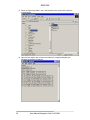
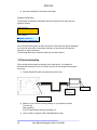
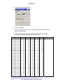
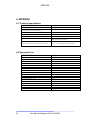
1
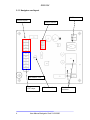
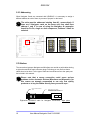
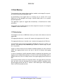
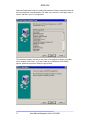
ENGLISH
User Manual
Navigator Card
Hw Rev. 1.20
English
HPAC - Code 272599
Revision 2
01.08.2005
1
User Manual Navigator Card 01.08.2005
ENGLISH
1.
INTRODUCTION................................................................................................3
1.1 FOREWORD ...........................................................................................................3
2.
HARDWARE .......................................................................................................3
2.1 NAVIGATOR CARD ................................................................................................3
2.2 HW CONFIGURATION ............................................................................................6
2.2.1 Hirobus connection.......................................................................................6
2.2.2 Sensor connection .........................................................................................8
2.2.3 Addressing...................................................................................................10
2.3 HIROBUS .............................................................................................................10
2.4 EPROM..............................................................................................................11
2.5 SENSORS .............................................................................................................12
2.6 HOUSING .............................................................................................................13
2.7 RS422 CONNECTION ..........................................................................................14
3. DATA MEMORY ..................................................................................................15
3.1 DATA STORING....................................................................................................15
3.2 SOFTWARE INSTALLATION ..................................................................................16
3.3 FIRST RUN CONFIGURATION ................................................................................19
3.5 DATA DOWNLOADING .........................................................................................22
4. APPENDIX.............................................................................................................26
4.1 TECHNICAL SPECIFICATION .................................................................................26
4.2 SPARE PARTS LIST ...............................................................................................26
2
User Manual Navigator Card 01.08.2005
ENGLISH
1. Introduction
1.1 Foreword
Unit management and diagnostic runs in parallel to the level of service that a
company can provide. There are several parameters to be watched in order to
understand how the machine runs and in order to anticipate possible failure, which
may happen into the unit.
To reach this target it is necessary to equip each unit with the Navigator card, which
can store all the necessary information for a programmable period. The Navigator
Card shall be connected with the Microface in order to share the information
collected. For this purpose a particular Eprom shall be installed in the Microface and
in the Hiromatic to manage and evaluate the further data collected.
This User Manual describes the Navigator Card and contains information concerning
the architecture of the refrigerant diagnose system.
2. Hardware
2.1 Navigator Card
The Navigator Card, is a microprocessor-based electronic board, which is used to
offer the option to monitor some additional temperature and pressure sensors,
capable to detect fundamental parameters to understand how the refrigerant circuit
works.
These parameters are:
•
•
•
•
•
Evaporating Pressure (Low pressure)
Condensing Pressure (High pressure)
Refrigerant discharge Temperature
Refrigerant suction Temperature
Refrigerant liquid Temperature
The refrigerant diagnosis requires 3 additional PTC-temperature sensors and 2
pressure sensors for each refrigerant circuit. Those information will be evaluated by
the Microface.
To connect this sensors to the Microface an additional Navigator-card is necessary (2
for twin-circuit units). The Navigator-card shall be connected to the Microface through
Hirobus.
Never add / remove Jumpers when Hirobus is connected on the
Navigator!
The Navigator Card can also be suitable to get the low pressure measurement, for
single or twin compressor circuit, in case to use the Fc+Dx options set in the software
(see Sw manual).
3
User Manual Navigator Card 01.08.2005
ENGLISH
2.1.1 Navigator card layout
RS422 connector
Pressure Inputs
Address Selector
Nav card rev. 1.20
Temperature
(PTC) Input
4
Microcontroller
User Manual Navigator Card 01.08.2005
Hirobus
connector
ENGLISH
2.1.2 Details of Inputs
High Pressure (+)
High Pressure (-)
Low Pressure (+)
Low Pressure (-)
PTC1 - Discharge
PTC2 - Suction
PTC3 - Liquid
Nav. Card rev 1.20
5
User Manual Navigator Card 01.08.2005
ENGLISH
2.2 Hw Configuration
2.2.1 Hirobus connection
The refrigerant diagnosis, as said above, requires 3 additional PTC-temperature
sensors and 2 pressure sensors for each refrigerant circuit. To connect this sensors
to the Microface the Navigator-card shall be connected to the Microface through
Hirobus, in the following way:
Navigator-card 1
EPROM
Microface
CONNECTION TYPE B
(HIROBUS):
8 wires screened flat cable.
Screen connected on both sides to
earth.
MAX LENGTH: 5m inside unit.
For twin-circuit units an additional Navigator Card shall be used and connected with
Hirobus as in the following drawing:
Navigator-card 1
Navigator-card 2
EPROM
Microface
CONNECTION TYPE B
(HIROBUS):
8 wires screened flat cable.
Screen connected on both sides
to earth.
MAX LENGTH: 5m inside unit.
6
User Manual Navigator Card 01.08.2005
ENGLISH
In case of other devices are connected on the same bus, like Humitemp, they can
share the same bus as in the example indicated.
Navigator-card 1
EPROM
Microface
CONNECTION TYPE B
(HIROBUS):
8 wires screened flat cable.
Screen connected on both sides to
earth.
MAX LENGTH: 5m inside unit.
to Humitemp,
EEAP,
Hirosensor 2T
Sensors
The T-adapter is necessary only in case the position of the Navigator board is not
closer to the MicroFace. Otherwise the Humitemp can be connected directly to the
Navigator card as indicated in the picture below:
Navigator-card 1
EPROM
Microface
to Humitemp,
EEAP,
Hirosensor 2T
Sensors
7
User Manual Navigator Card 01.08.2005
ENGLISH
2.2.2 Sensor connection
The suitable pressure transducer to be connected to the Navigator card are the
following:
High pressure:
Low pressure:
Keller PA
Keller PA
21, range 0..30bar, LH code 275306
21, range 0..10bar, LH code 275304
The pressure transducers shall be connected in the following way to the board:
HP
V1+ BROWN
V1- WHITE
LP
V2+ BROWN
V2- WHITE
The PTC sensor for the connection to the Navigator card are the following:
PTC length 2mt,
PTC length 10mt,
LH code 275183
LH code 275155
The PTC sensor shall be connected to the board as the picture below:
RED
Discharge
WHITE
Suction
RED
WHITE
Liquid
RED
WHITE
8
User Manual Navigator Card 01.08.2005
ENGLISH
In case of using the Navigator card in Address 3 (for Fc + Dx) the following
configuration shall be used:
The suitable pressure transducer to be connected to the Navigator card are the
following:
Low pressure 1st compressor: Keller PA
Low pressure 2nd compressor: Keller PA
21, range 0..10bar, LH code 275304
21, range 0..10bar, LH code 275304
The pressure transducers shall be connected in the following way to the board:
LP1
V1+ BROWN
V1- WHITE
LP2
V2+ BROWN
V2- WHITE
The order connection shall be according to chapter 2.1.2 and the following table
resume the connection order:
Navigator Card Layout
Input
Purpose
V1+
V1V2+
V2PTC1
PTC2
PTC3
High pressure supply
High pressure signal
Low pressure supply
Low pressure signal
Temp. Sensor1
Temp. Sensor2
Temp. Sensor3
Condensing pressure
9
Evaporating pressure
Refrigerant Discharge temperature
Refrigerant Suction temperature
Refrigerant Liquid temperature
User Manual Navigator Card 01.08.2005
ENGLISH
2.2.3 Addressing
When Navigator Cards are connected with HIROBUS, it is necessary to assign a
different address to each of them, by means of jumpers on the board.
The units must be addressed starting from #1, consecutively. If
there are 2 Navigator cards on the same unit, they shall have
address 1 and 2. In case of using the Navigator as expansion
board for Fc+Dx, single or dual compressor, Address 3 shall be
selected.
Address #1
Address #2
Address #3
3
3
3
2
2
2
1
1
1
2.3 Hirobus
The connections between Navigator and Microface are carried out with cables having
a eight wires and RJ45 male connector plugs. Following you can find how these
cables have to be done. For the type of cable and connectors refer to the spare part
list included in this manual.
Please note that a wrong connection could cause serious
problems to the electronic devices (Microface and Hiromatic); for
this reason we strongly recommend to use only first quality
products or to buy the cables directly from your sales reps..
EIGHT POLES MODULAR
JACK
EIGHT WIRES FLAT CABLE.
USE SCREENED CABLE WHEN CABLE
IS RUNNING OUTSIDE THE UNIT.
Eight-wires HIROBUS cable for Navigator connections, eight poles
connectors;
10
User Manual Navigator Card 01.08.2005
ENGLISH
2.4 EPROM
The Eprom is the device, which stores the Program the Microface has to work with. It
doesn’t store any user-settings; this is done by the Microface itself (in the RAM and
the E2Prom). The Version Name and the Number are printed on the Label of the
Eprom.
The following Eproms shall be used to embed the Navigator Card in the
EVM 1.60.043 (or higher) 2 MBit
E48 1.60.043 (or higher) 2MBIT
E1G 1.60.043 (or higher) 2 MBit
EVGL1 1.60. 043 (or higher) 4 MBit
EVGL1 2.60. 043 (or higher) 4 MBit
HPAC, for Microface E 24VAC/DC
HPAC, FOR MICROFACE E 48VDC
HPAC, for HIROMATIC G
HPAC, for HIROMATIC E
HPAC, for HIROMATIC E
Un-power the Microface before mounting/dismounting the Eprom.
Remove Eprom only with special tool; never use a Screwdriver.
For correct direction of mounting please refer to the Micorface
and Hiromatic Manuals. Compare the Mark in the Eprom with the
direction in the Drawing.
11
User Manual Navigator Card 01.08.2005
ENGLISH
2.5 Sensors
PTC Temperature Sensor
The PTC Sensor is used in Air-Conditioners as well as in Chillers/Superchillers.
There are different Types and lengths available: please refer to the Spare Part List.
PTC Sensors are temperature-sensors, changing the resistance according to the
temperature (positive temperature coefficient). The connection is 2 poles. The length
of the cable for the sensor ranges from 1.5 to 10 meters.
Measuring
Element
Cable
PTC Sensor
Pressure Transducers
The KELLER Series 21/21PRO are extremely reliable and cost effective pressure
transmitters. They are use to convert hydraulic or pneumatic pressure into an
electrical current output signal in the reange 4..20 mA, linearly proportional to the
input pressure. The signal can be sent directly to the Navigator Card which provides
also to furnish the phantom supply for the transducer. The connection is 2 poles. The
length of the cable for the transducer is 2 meters.
Pressure Transducer
Cable
Pressure Transducer
12
User Manual Navigator Card 01.08.2005
ENGLISH
2.6 Housing
The Navigator card is compatible with the Microface housing, as indicated in the
following pictures. This encansing could be used as alternative solution to the 4
plastic pins.
Usage of microface’s
housing for one Navigator.
Note the stop
point on the
plastic
Usage of microface’s
housing for two Navigator.
13
User Manual Navigator Card 01.08.2005
ENGLISH
2.7 RS422 Connection
To download the data stored in the navigator it is necessary to use a RS422/RS232
converter. The connector where to attach the cable is indicated in the picture below:
RJ9 female connector:
RS422 Type connection
The PinOut of the connector is the following:
Connector RJ9:
1 RS422 RX2 RS422 RX+
3 RS422 TX4 RS422 TX+
The parameters issued by the communications are the followings:
57600 bauds
8 data bits
No parity
1 bit stop
No flow control
LH according the following code codifies the suitable cable, for issue the
communication within the card and the PC.
The cable shall be connected in the following way to download data from the card:
cable
Laptop PC
R232 port
dB9 connector
Rj9 female connector
14
User Manual Navigator Card 01.08.2005
ENGLISH
3. Data Memory
To download the data, special software shall be installed on the Laptop Pc to permit
the communication with the Navigator card.
For downloading of the logged data it is necessary only to connect a PC to the
RS422 port of the Navigator card (using a specific cable) and to run a specific
download application.
The application exports all logged data automatically in Excel-format for further
processing.
The program itself connects through one of the computer’s com-ports, it is enough to
“CONNECT” and to “GET DATA”.
3.1 Data storing
The Navigator card has a 4 MBit flash memory on board, which allows to store the
logged data.
For logging intervals every 1 second, all 5 sensors, the logging time is 22,4 hours.
For logging intervals every 5 seconds, only 1 sensors, the logging time is 560 hours.
The selectable logging interval ranges from 1 second (22,4 hours for 5 sensors, 112
hours for 1 only sensor) to 12,75 minutes (app. 2 years for 5 sensors, app. 10 years
for 1 only sensor).
Logging of various sensors can be enabled / disabled separately for each individual
sensor, the logging interval can be set and is valid for all sensors with logging
enabled.
In case of exceeding a specific threshold (example: dangerous high pressure), the
logging interval changes automatically to 1 second. If this “critical operating mode” is
passed without any cut-out of safety devices, the original logging interval will be set
back.
If the critical operation results in a compressor failure, the logging will stop 5 minutes
after the failure, with the advantage that the logging resolution, regardless which
general logging interval was set, is 1 second – when reaching the “critical operating
mode” until 5 minutes after the fault.
15
User Manual Navigator Card 01.08.2005
ENGLISH
3.2 Software installation
The file is distributed and stored inside a Zip archive, named as Nav031203.zip
Once decompressed it generates a file Named as Nav.exe. Launching this file the Pc
will proceed automatically to create the installation of the program:
Once compared the above window press “Next” to go on with the installation.
16
User Manual Navigator Card 01.08.2005
ENGLISH
Select the Destination Folder for installing the software. Please note that the Data will
be stored inside the same destination. So make sure it will be in a safe place easy to
recover and find in your PC configuration.
The installation program will ask you the name of the program manager group that
will be created. Press “Next “ if you don’t want any modifications to the default
options; otherwise proceed to modify the group name.
17
User Manual Navigator Card 01.08.2005
ENGLISH
Finally, pressing “Next”, the last warning will let to start the installation of the main
program in your PC.
At the end of the successfully installation the above message will be displayed. Press
“Finish” to go ahead.
18
User Manual Navigator Card 01.08.2005
ENGLISH
3.3 First run configuration
Once finished to install the program the following steps should be performed in order
to ensure the correct data synchronization between the data stored in the Navigator
Card and the indication of the Hiromatic display:
1) Go to the folder where you have installed the program. (For example, as the
case above: C:\MEC\NavigatorBoard).
2) Explore the folder, the following files should be present:
3) Double click on the Nav.exe file, the following window shall appear:
4) Go to File and select Exit.
19
User Manual Navigator Card 01.08.2005
ENGLISH
5) Return to explore the folder, now a file named as Nav.cfg should be present
in the directory:
6) Open the Nav,cfg file with a normal text editor (for example Notepad), the
following parameters will appear:
20
User Manual Navigator Card 01.08.2005
ENGLISH
7) MAKE the following modification:
a) Change CalcValues from 0 to 1.
b) Insert the PTC correction according to the settings made on the Hiromatic
window MULTIPLIED by 10.
Example:
If in the Hiromatic window the following offsets were selected:
520
521
522
523
524
525
526
527
NAVIGATOR 6 / 6 (CALIBRATION)
UNIT 1
PW (L0) ? ? ? ?
READ OFFSET
C1 DISCH. T
30.5 0,7
°C
C1 SUCT. T
30.5 2,6
°C
C1 LIQU. T
30.5 + 0.0
°C
C2 DISCH. T
30.5 + 0.0
°C
C2 SUCT. T
30.5 + 0.0
°C
C2 LIQU. T
30.5 + 0.0
°C
In the Nav.cfg file the following variables should be changed accordingly to it:
PTC1_Temp_Offset_In_Tenth_K=7
PTC2_Temp_Offset_In_Tenth_K=26
PTC3_Temp_Offset_In_Tenth_K=0
c) Insert the High and low pressure settings accordingly to what selected in
the Hiromatic MULTIPLIED by 10.
Example:
If in the Hiromatic window the following correction parameters were selected:
490
491
492
493
494
495
496
497
NAVIGATOR 3 / 6 (SETUP)
REFRIGERANT:
HP1:
0.0V= -7,5 bar
LP1:
0.0V= -2,5 bar
HP1 / LP1: 4.7V 12.3 bar
HP2:
0.0V= -6.0 bar
LP2:
0.0V= -6.0 bar
HP2 / LP2: 4.7V 12.3 bar
UNIT 1
R407C
10V= 31,0
10V= 10,5
2.5V 5.7
10.0V= 30.0
10.0V= 10.0
2.5V 5.7
bar
bar
bar
bar
bar
bar
In the Nav.cfg file the following variables should be changed accordingly to it:
P1_Pressure_At_Minimum_In_Tenth_Bar= -75
P1_Pressure_At_Maximum_In_Tenth_Bar=310
P1_Voltage_At_Minimum_In_Tenth_Volt= 0
P1_Voltage_At_Maximum_In_Tenth_Volt=100
P2_Pressure_At_Minimum_In_Tenth_Bar= -25
P2_Pressure_At_Maximum_In_Tenth_Bar=105
P2_Voltage_At_Minimum_In_Tenth_Volt=0
P2_Voltage_At_Maximum_In_Tenth_Volt=100
21
User Manual Navigator Card 01.08.2005
ENGLISH
8) Save the configuration and exit the text editor.
Standard configuration
The following configuration parameters should be applied for the High and Low
pressure sensors:
High Pressure:
SENSOR OFFSET (hp)
0.0V=-7,5 bar / 10V=31.0 bar
Low Pressure:
SENSOR OFFSET (lp)
0.0V=-2.5 bar / 10V=10.5 bar
Once configured the system the data read from the Hiromatic through the Navigator
must coincide both with the manometer indication on the machine and with the
indication of data to download.
The following tables were verified for both high and low pressure.
3.5 Data downloading
Once configured the system accordingly to the steps above, it is possible to
download the data stored in the non-volatile memory of the navigator following the
next steps:
1) Connect Rs422/232 cable according the picture below:
Laptop PC
R232 port
dB9 connector
Rj9 female connector
2) Make sure you have the following settings on your operative system:
Time: hh:mm
Date: gg.MM.yy
If NOT, please change settings according to it.
3) Click on Start> Programs> MEC> NavigatorBoard> Nav
22
User Manual Navigator Card 01.08.2005
ENGLISH
4) The following window will appear:
5) Click on CONNECT
6) Click on GET DATA, starting form this point the program will download the
data from the Navigator.
7) The data will be stored in a folder named as Data under the installation
directory. The data will appear as a form of Excel files:
TIME
13.01.2004 14:10:24
13.01.2004 14:10:25
13.01.2004 14:10:26
13.01.2004 14:10:27
13.01.2004 14:10:28
13.01.2004 14:10:29
13.01.2004 14:10:30
13.01.2004 14:10:31
13.01.2004 14:10:32
13.01.2004 14:10:33
13.01.2004 14:10:34
13.01.2004 14:10:35
13.01.2004 14:10:36
13.01.2004 14:10:37
13.01.2004 14:10:38
13.01.2004 14:10:39
13.01.2004 14:10:40
13.01.2004 14:10:41
13.01.2004 14:10:42
13.01.2004 14:10:43
13.01.2004 14:10:44
13.01.2004 14:10:45
13.01.2004 14:10:46
13.01.2004 14:10:47
13.01.2004 14:10:48
13.01.2004 14:10:49
13.01.2004 14:10:50
13.01.2004 14:10:51
23
PTC0
36,2
36,2
36,2
36,1
36,1
36,1
35,9
36,1
35,9
35,9
35,9
35,8
35,9
35,8
35,6
35,8
35,6
35,6
35,6
35,5
35,5
35,5
35,5
35,3
35,5
35,3
35,3
35,3
PTC1
17,9
18,1
18,1
18,1
18,1
18,1
18,1
18,1
18,1
18,1
18,1
18,1
18,1
18,1
18,1
18,1
18,1
18,1
18,1
18,2
18,2
18,2
18,2
18,2
18,2
18,2
18,2
18,2
PTC2
27,3
27,3
27,2
27,3
27,3
27,2
27,3
27,2
27,2
27,3
27,2
27,2
27,2
27,1
27,2
27,1
27,2
27,2
27,2
27,2
27,2
27,1
27,1
27,1
27,1
27,1
27,1
27,1
P1
6,3
6,3
6,3
6,3
6,3
6,3
6,3
6,3
6,3
6,3
6,3
6,3
6,3
6,35
6,3
6,35
6,35
6,3
6,35
6,35
6,35
6,35
6,35
6,35
6,35
6,35
6,35
6,35
P2
6,37 Page 1292
6,37
6,37
6,37
6,37
6,38
6,38
6,38
6,38
6,38
6,38
6,4
6,4
6,4
6,4
6,4
6,4
6,4
6,4
6,4
6,4
6,4
6,4
6,4
6,4
6,4
6,41
6,41
User Manual Navigator Card 01.08.2005
ENGLISH
The first column (TIME) indicates the data and the time of the sample stored
inside the non-volatile memory of the navigator.
The other columns indicate:
PTC0
PTC1
PTC2
P1
P2
Refrigerant discharge temperature
Refrigerant suction temperature
Refrigerant liquid temperature
High pressure
Low pressure
With this data it is possible to make tables, comparisons and charts:
Temperarature Probes - Compressor ON
70
60
Temperature [°C]
50
40
Discharge Temp
Liquid Temp
Suction Temp
30
20
10
0
24
User Manual Navigator Card 01.08.2005
ENGLISH
Pressure Transducers - Compressor ON
20
18
16
Pressure [bar]
14
12
High Pressure
10
Low Pressure
8
6
4
2
0
25
User Manual Navigator Card 01.08.2005
ENGLISH
4. APPENDIX
4.1 Technical specification
NAVIGATOR CARD
Power Supply
Directly form HiroBus slave bus
Analogue In
3
(resistive for PTC 2k – KTY81-210 probes)
Analogue In (4-20 mA) with 20V phantom supply
2
Storage Temperature
-10 (not condensating) to +65°C
Maximun Operating Temperature
0 (not condensating) to +55°C
Microcontroller
Used ATMEL ATMega8, 10 bit ADC, 8KBytes FLASH,
1KByte RAM, 512Bytes EEPROM
Non volatile memory
EEprom AT45DB041B with 4Mbit memory (1,000,000,000
4 MBit Memory (Flash) with time/date to store sensors data
write cycles) for about 1000 values with time index
4.2 Spare parts list
26
DESCRIPTION
CODE
Navigator Card
274010
Pressure Transducer Keller PA21M 0..10 Bar
275304
Pressure Transducer Keller PA21M 0..30 Bar
275306
Microface E (Evolution) board
275297
Probe temperature PTC
275183
Probe PTC 2 kohm L = 10 m
275155
EPROM Microface EVM 160***
275791
EPROM HiromaticE EVEL1 160***
275789
EPROM HiromaticG E1G 160***
275790
Flat cable 8 way M-M L = 1 m
275607
Flat cable 8 way M-M L = 10 m
275610
Flat cable 8 way screened (specify length)
275626
Cable RS422/RS232 converter
274015
Manual Navigator card
272599
Kit Navigator card
480115
Plastic cover for holder
271443
Plastic holder for Microface compatible with Navigator
270002
User Manual Navigator Card 01.08.2005