1
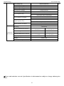
Invtak Energy www.invtak.com SP Series 600W&1,000W Pure Sine Wave Inverter/Charger User’s Manual For Models SP0612120 SP0612230 SP1012120 SP1012230 1 Invtak Energy www.invtak.com Table of Contents 1 Important Safety Information ......................................................................................................................... 3 1.1 General Safety Precautions .......................................................................................................................... 3 1.2 Precautions When Working with Batteries .................................................................................................. 4 2 Introduction ..................................................................................................................................................... 4 2.1 General Information ..................................................................................................................................... 4 2.4 Features ....................................................................................................................................................... 6 2.5 Electrical Performance ............................................................................................................................... 6 2.5.1 Invert .................................................................................................................................................. 6 2.5.2 AC Charger ........................................................................................................................................ 7 2.5.3 Transfer .............................................................................................................................................. 9 2.5.4 Remote Operation .............................................................................................................................. 9 2.5.5 Protections.......................................................................................................................................... 9 2.5.7 LED Indicator .................................................................................................................................. 10 2.5.8 Audible Alarm .................................................................................................................................. 10 2.5.9 FAN Operation ................................................................................................................................. 11 2.5.10 DIP Switches .................................................................................................................................. 11 2.5.11 Auto Generator Start(Optional) ...................................................................................................... 13 2.5.12 Battery Temperature Sensing(Optional) ........................................................................................ 13 2.5.13 Other Features ................................................................................................................................ 13 3 Installation..................................................................................................................................................... 15 3.1 Location .............................................................................................................................................. 15 3.2 DC Wiring Recommendation .............................................................................................................. 15 3.3 AC Wiring Recommendations ............................................................................................................ 16 3.4 Grounding ........................................................................................................................................... 16 3.5 Mounting Flange ................................................................................................................................. 16 4 Maintenance & Troubleshooting .................................................................................................................. 19 5 Warranty ....................................................................................................................................................... 21 6 Model Numbering ......................................................................................................................................... 21 Appendix 1 : SP Series Inverter/Charger Spec Sheet ...................................................................................... 22 2 Invtak Energy www.invtak.com 1 Important Safety Information Save This Manual! Read this manual before installation, it contains important safety, installation and operating instructions. Keep it in a safe place for future reference. All wiring must follow the National Electric Code, Provincial or other codes in effect at the time of installation, regardless of suggestions in this manual. All wires should be copper conductors. 1.1 General Safety Precautions 1.1.1 Before installing and using the SP Series Pure Sine Wave Inverter/Charger, read the manual and cautionary markings on the Inverter/Charger enclosure. Be sure to read all instructions and cautionary markings for any equipment attached to this unit. Installers must be certified technicians or electricians. 1.1.2 This product is designed for indoor/compartment installation. Do not expose the inverter/charger to rain, snow, spray, bilge or dust. To reduce risk of hazard, do not cover or obstruct the ventilation openings. Do not install the inverter/charger in a zero-clearance compartment. Overheating may result. Allow at least one inch of clearance around the inverter for air flow. Make sure that the air can circulate freely around the unit. A minimum air flow of 145CFM is required. 1.1.3 To avoid a risk of fire and electronic shock. Make sure that existing wiring is in good electrical condition; and that wire size is not undersized. Do not operate the Inverter with damaged or substandard wiring. 1.1.4 This equipment contains components which can produce arcs or sparks. To prevent fire or explosion do not install in compartments containing batteries or flammable materials or in locations which require ignition protected equipment. This includes any space containing gasoline-powered machinery, fuel tanks, or joints, fittings, or other connection between components of the fuel system. See Warranty for instructions on obtaining service. 1.1.5 Do not dis-assemble the Inverter/Charger. It contains no user serviceable parts. Attempting to service the Inverter/Charger yourself may result in a risk of electrical shock or fire. Internal capacitors remain charged after all power is disconnected. 1.1.6 To reduce the risk of electrical shock, disconnect both AC and DC power from the Inverter/Charger before attempting any maintenance or cleaning. Turning off controls will not reduce this risk CAUTION: Equipment damage The output side of the inverter’s AC wiring should at no time be connected to public power or a generator. This condition is far worse than a short circuit. If the unit survives this condition, it will shut down until corrections are made. Installation should ensure that the inverter’s AC output is, at no time, connected to its AC input. WARNING: LIMITATIONS ON USE SPECIFICALLY, PLEASE NOTE THAT THE INVERTER/CHARGER SHOULD NOT BE USED IN CONNECTION WITH LIFE SUPPORT SYSTEMS OR OTHER MEDICAL EQUIPMENT OR DEVICES. WE MAKE NO WARRANTY OR REPRESENTATION IN CONNECTION WITH THEIR PRODUCTS FOR SUCH USES. USING THE INVERTER/CHARGER WITH THESE PARTICULAR EQUIPMENTS IS AT YOUR OWN RISK. 3 Invtak Energy www.invtak.com 1.2 Precautions When Working with Batteries 1.2.1 If battery acid contacts skin or clothing, wash immediately with soap and water. If acid enters eye, immediately flood eye with running cold water for at least 20 minutes and get medical attention immediately. 1.2.2 Never smoke or allow a spark or flame in vicinity of battery or engine. 1.2.3 Do not drop a metal tool on the battery. The resulting spark or short-circuit on the battery of other electrical part may cause an explosion. 1.2.4. Remove personal metal items such as rings, bracelets, necklaces, and watches when working with a lead-acid battery. A lead-acid battery produces a short-circuit current high enough to weld a ring or the like to metal, causing a severe burn. 1.2.5 To reduce the risk of injury, charge only rechargeable batteries such as deep-cycle lead acid, lead antimony, lead calcium gel cell, absorbed mat, and NiCad/NiFe or Lithium battery. Other types of batteries may burst, causing personal injury and damage. 2 Introduction 2.1 General Information Thank you for purchasing the SP Series Pure Sine Wave Inverter/Charger. The SP Series Pure Sine Wave Inverter/Charger is a transformer based inverter and battery charger with an unprecedented conversion efficiency of 90%. It features power factor corrected, sophisticated multi-stage charging control and pure sine wave output with high surge capability to meet power needs of all sorts of demanding loads without putting the equipment at risk. In response to the increasing demand of more advanced battery charging, our engineering team equipped the inverter with a Battery Temperature Sensing probe for increased charging precision. The generous 300% surge capacity of 20 seconds makes it possible to support demanding inductive loads. The AC/Battery priority, auto generator start functionality and optional built-in charger make it ideally suitable to work in backup power or anti-idle applications. When customized to Battery priority mode via a DIP switch, the inverter will extract maximum power from external power sources and a minimal cycle of battery will be required. With the availability of auto generator start, an electrical generator can be integrated into the system and started when the battery voltage goes low. With audible buzzer and remote LCD panel, the inverter gives the users comprehensive information of the operation status, making it easier for maintenance and troubleshooting. Thus the SP Series Pure Sine Wave Inverter/Charger is suitable for applications including renewable energy systems, utility, truck, RV and emergency vehicles etc. To get the most out of the power inverter, it must be installed, used and maintained properly. Please read the instructions in this manual before installing and operating. 4 Invtak Energy www.invtak.com 2.3 Mechanical Drawing 5 Invtak Energy www.invtak.com 2.4 Features Smart remote LCD control Auto Generator Start(Optional) Battery Temperature Sensing for increased charging precision(Optional) Manual 50Hz/60Hz output frequency switch Maximum 90% conversion efficiency High surge output capability, 300% peak load for 20 seconds Low quiescent current Battery type selector for 8 types of batteries and de-sulphation for completely drained batteries 10ms transfer time from AC to battery for continuous load operation 15 sec DC to AC transfer delay, improved protection for generator driven loads Thermally controlled variable speed fan for more efficient cooling Extensive protections against various harsh situations 2.5 Electrical Performance 2.5.1 Invert Topology The SP series pure sine wave inverter/charger is built according to the following topology. Invert: Full Bridge Topology. Charge: Isolated Boost Topology When operating in invert mode, the direct current (DC) that enters the inverter from the batteries is filtered by a large input capacitor and switched “On” and “Off” by the Metal Oxide Silicon Field Effect Transistors (MOSFET) at a rate of 50 Hz or 60Hz, and directed into the transformer which steps the voltage up to 230 or 120 volts. The unit has a 16bit, 4.9MHZ microprocessor to control the output voltage and frequency as the DC input voltage and/or output load varies. Because of high efficiency MOSFETs and the heavy transformers, it outputs PURE SINE WAVE AC. The peak invert efficiency of SP series is 90%. Overload Capacity The SP series inverter/charger has different overload capacities, making it ideal to handle demanding loads. 1 For 110%<Load<125% (±10%), no audible alarm in 14 minutes, beeps 0.5s every 1s in the 15th minute, and Fault (Turn off) after the 15th minute. 2 For 125%< Load<150% (±10%), beeps 0.5s every 1s and Fault (Turn off) after the 1 minute. 3 For 300%≧Load>150% (±10%), beeps 0.5s every 1s and Fault (Turn off) after 20s. Caution: After the inverter is switched on, it takes 3-5 seconds for it to self diagnose and get ready to deliver full power. Hence, always switch on the load(s) after a few seconds of switching on the inverter. Avoid switching on the inverter with the load already switched on. This may prematurely trigger the overload protection. When a load is switched on, it may require initial higher power surge to start. Hence, if multiple 6 Invtak Energy www.invtak.com loads are being powered, they should be switched on one by one so that the inverter is not overloaded by the higher starting surge if all the loads are switched on at once. 2.5.2 AC Charger The SP Series pure sine wave inverter/charger is equipped with an active PFC (Power Factor Corrected) multistage battery charger. The PFC feature is used Battery type selector to control the amount of power used to charge the Switch Boost / Float / Description batteries in order to obtain a power factor as close as setting Vdc Vdc possible to 1. 0 Charger Off Unlike other inverters whose max charging current 1 Gel USA 14.0 13.7 decreases according to the input AC voltage, SP 2 AGM 1 14.1 13.4 series pure sine wave inverter/charger is able to 3 Lithium Ion (LiFeP04) 14.6 13.7 output max charge current as long as input AC 4 Sealed lead acid 14.4 13.6 voltage is in the range of 164-243VAC(95-127VAC 5 Gel EURO 14.4 13.8 for 120V model), and AC freq is in the range of 6 Open lead acid 14.8 13.3 48-54Hz(58-64Hz for 60Hz model). 7 Calcium 15.1 13.6 The SP series pure sine wave inverter/charger has a 15.5 (4 Hours 8 De sulphation very rapid charge current available, and the max then Off) charge current can be adjusted from 0%-100% via a 9 Not used liner switch on the DC side of the inverter. This will be helpful if this powerful charger apply charging on a small capacity battery bank. Choosing “0” in the battery type selector will disable charging function. There are three main charging stages: Bulk Charging: This is the initial stage of charging. While Bulk Charging, the charger supplies the battery with controlled constant current. The charger will remain in Bulk charge until the Absorption charge voltage (determined by the Battery Type selection) is achieved. Software timer will measure the time from charger start until the battery charger reaches 0.3V below the boost voltage, then take this time as T0 and T0×10 = T1. Absorb Charging: This is the second charging stage and begins after the absorb voltage has been reached. Absorb Charging provides the batteries with a constant voltage and reduces the DC charging current in order to maintain the absorb voltage setting. In this period, the inverter will start a T1 timer; the charger will keep the boost voltage in Boost CV mode until the T1 timer has run out. Then drop the voltage down to the float voltage. The timer has a minimum time of 1 hour and a maximum time of 12 hours. Float Charging: The third charging stage occurs at the end of the Absorb Charging time. While Float charging, the charge voltage is reduced to the float charge voltage (determined by the Battery Type selection*). In this stage, the batteries are kept fully charged and ready if needed by the inverter. If the A/C is reconnected or the battery voltage drops below 12Vdc/24Vdc/48Vdc, the charger will reset the cycle above. If the charge maintains the float state for 10 days, the charger will deliberately reset the cycle to protect the battery. 7 Invtak Energy www.invtak.com De-sulphation The de-sulphation cycle on switch position 8 is marked in red because this is a very dangerous setting if you do not know what you are doing. Before ever attempting to use this cycle you must clearly understand what it does and when and how you would use it. What causes sulphation? This occurs with infrequent use of the batteries, nor if the batteries have been left discharged so low that they will not accept a charge. This cycle is a very high voltage charge cycle especially designed to try to break down the sulphated crust that is preventing the plates from taking a charge and thus allow the plates to clean up and accept a charge once again. Warning! The de-sulphation charging should not be carried out on batteries with good conditions. Charging depleted batteries The SP series pure sine wave inverter/charger allows start up and through power with depleted batteries. For 12VDC models, after the battery voltage goes below 10V, if the switch is still(and always) kept in "ON" position, the inverter is always connected with battery whose voltage doesn’t drop below 2V, the inverter will be able to charge the battery once qualified AC inputs. Before the battery voltage going below 9VDC, the charging can activated when the switch is turned to “Off”, then to “ON”. When the voltage goes below 9VDC, and the power switch is turned to “OFF” or disconnect the inverter from battery, the inverter will not be able to charge the battery once again, because the CPU lose memory during this process. Charging current for each model Model Wattage 600W 1000W Battery Voltage 12 Vdc 12 Vdc 8 Charging Current 25±5 Amps 40±5 Amps Invtak Energy www.invtak.com The charging capacity will go to peak in around 3 seconds; this may probably cause a generator to drop frequency, making inverter transfer to battery mode. It is suggested to gradually put charging load on the generator by switching the charging switch from min to max, together with the 15s switch delay, our inverter gives the generator enough time to spin up. Caution: Please use a small jeweler’s style flat-head screwdriver to turn the charge current control switch gently to avoid breakage due to over-turning. To guarantee the best performance of AC charger when the AC input is from a generator, the standby generator should be of at least 150% higher capacity than the inverter. Warning! Operation with an under-rated generator or generator with unqualified wave form may cause premature failure which is not under warranty. 2.5.3 Transfer While in the Standby Mode, the AC input is continually monitored. Whenever AC power falls below the VAC Trip voltage (154 VAC, default setting), the inverter automatically transfers back to the Invert Mode with minimum interruption to your appliances - as long as the inverter is turned on. The transfer from Standby mode to Inverter mode occurs in approximately 10 milliseconds. And it is the same time from Inverter mode to Standby mode. Though it is not designed as a computer UPS system, this transfer time is usually fast enough to hold them up. There is a 15-second delay from the time the inverter senses that continuously qualified AC is present at the input terminals to when the transfer is made. This delay is built in to provide time for a generator to spin-up to a stable voltage and avoid relay chattering. The inverter will not transfer to generator until it has locked onto the generator’s output. This delay is also designed to avoid frequent switch when input utility is unstable. 2.5.4 Remote Operation The inverter can also be connected to an external LCD display through the REMOTE LCD PORT. The whole SP Series inverter is designed with extraordinarily low idle power consumption which is approximately 1.5% of its rated power. SP Series Inverter/Charger Idle Power Consumption (in Watts) Power Saver Off Power Saver Auto Model Idle(Max) 3Secs(Max) Unit Off Charging 600W 18W 7.5W 3W 1KW 22W 9W For more detailed technical information, please contact us. 2.5.5 Protections The SP series inverter/charger is equipped with extensive protections against various harsh situations/faults. These protections include: 9 Invtak Energy AC Input over voltage protection/AC Input low voltage protection Low battery alarm/High battery alarm Over temperature protection/Over load protection Short Circuit protection (1s after fault) Back feeding protection on the AC output www.invtak.com When Over temperature /Over load occur, after the fault is cleared, the master switch has to be reset to restart the inverter. The Low battery voltage trip point can be customized from defaulted value of 10VDC to 10.5VDC through the SW1 on the DIP switch. The inverter will go to Over-temp protection when the heat sink temps. ≥105ºC (221℉), and will go to Fault (shutdown Output) after 30 seconds. After temp drops to 90ºC (194℉), the switch has to be reset to activate the inverter. The SP series Inverter has back feeding protection which avoids presenting an AC voltage on the AC input terminal in Invert mode. After the reason for fault is cleared, the inverter has to be reset to start working. 2.5.7 LED Indicator 2.5.8 Audible Alarm 10 Line Mode Inverter Mode Fast Charge Float Charge Alarm Over Temp Over Load Power Saver Battery Type Selector AC MODE GREEN LED on “AC Input Mode” INVERTER ON GREEN LED on “Invert Mode” FAST CHARGE Yellow LED on “Fast CHG” FLOAT CHARGE GREEN LED on “Float CHG” OVER TEMP TRIP RED LED on “Over Temp” OVER LOAD TRIP RED LED on “Over Load” CHARGING GREEN LED on “Ready Position” Please refer to ‘Indicator and Buzzer’ for the detailed information. Invtak Energy www.invtak.com The inverter also gives audible alarms when the following situations occur. Inverter green LED Lighting, and the buzzer beep 0.5s every 5s. Battery Voltage Low Inverter green LED Lighting, and the buzzer beep 0.5s every 1s, Battery Voltage High and Fault after 60s. (1)110%<load<125%(±10%), No audible alarm in 14 minutes, Beeps 0.5s every 1s in 15th minute and Fault after 15 minutes; Invert Mode Over-Load (2)125% <load<150%(±10%), Beeps 0.5s every 1s and Fault after 60s; (3)Load>150%(±10%), Beeps 0.5s every 1s and Fault after 20s; Heat sink temp. ≥105ºC(221℉), Over temp red LED Lighting, beeps Over Temperature 0.5s every 1s; 2.5.9 FAN Operation For 600W-1KW models, there is one multiple controlled DC fan. The DC fans are designed to operate according to the following logic: Condition HEAT SINK TEMPERATURE CHARGER CURRENT LOAD Percentage (INV MODE) Enter Condition T ≤ 60℃(140℉) 65℃(149℉)≤ T < 85 ℃(185℉) T > 85℃(185℉) I ≤ 15% 20%< I ≤ 50%Max I > 50%Max Load < 30% 30% ≤ Load < 50% Load ≥ 50% Leave condition T > 65℃(149℉) T ≤ 60℃(140℉) or T ≥ 85℃(185℉) T ≤ 80℃(176℉) I ≥ 20% I≤ 15% or I > 50%Max I ≤ 40%Max Load ≥ 30% Load ≤ 20% or Load ≥ 50% Load ≤ 40% Speed OFF 50% 100% OFF 50% 100% OFF 50% 100% Allow at least 1 inch of clearance around the inverter for air flow. Make sure that the air can circulate freely around the unit. Fan noise level <60db at a distance of 1m 2.5.10 DIP Switches On the DC end of inverter, there are 5 DIP switches which enable users to customize the performance of the device to suit the specific configuration. Switch NO SW1 SW2 SW3 SW4 SW5 Switch Function Low Battery Trip Volt AC Input Range Power Saver & READY Output Frequency Battery/AC Priority Position: 0 10.0VDC 100-135VAC 184-253VAC READY 50Hz Utility Priority Position: 1 10.5VDC 90-135VAC 154-253VAC (40Hz+) Power Saver 60Hz Battery Priority Low Battery Trip Volt: Deep discharge of the lead acid battery leads to high losses in capacity and early aging. In different applications, different low voltage disconnection level is preferred. For example, for solar application, user intended to have less DOD (Depth of Discharge) to prolong the battery cycle life (mobile application, users intend to have more DOD to reduce battery capacity and on board weight). 11 Invtak Energy www.invtak.com For 12VDC model, the Low Battery Trip Volt is set at 10.0VDC by default. It can be customized to 10.5VDC using SW1 (this is to prevent batteries from over-discharging while there is only a small load applied on the inverter). AC Input Range: There are different acceptable AC input ranges for different kinds of loads. For some relatively sensitive electronic devices, a narrow input range of 184-253VAC (100-135V for 120VAC model) is required to protect them. While for some resistive loads which work in a wide voltage range, the input AC range can be customized to 154-253VAC (90-135V for 120VAC model), this helps to power loads with the most AC input power without frequent switches to the battery bank. In order to make the inverter accept dirty power from a generator, when the SW2 is switched to position “1”, the inverter will bypass an AC input with a higher voltage(164-264Vac for 230Vac model) and wider frequency (40Hz plus for 50Hz/60Hz). Accordingly, the AC charger will also work in a higher voltage (174-254Vac for 230Vac model) wider freq range (43Hz plus for 50Hz/60Hz). This will avoid frequent switches between battery and generator. But some sensitive loads will suffer from the low quality power. The pros and cons should be clearly realized. Power Saver & READY Under the Battery Priority Mode (SW5 in position “1”), the inverter can be switched between two modes: Power Saver Mode (SW3 in position “1”) and READY (SW3 in position “0”). The power Switch should be in “READY” position all the time for using these functions. In Power Saver Mode, the inverter is initially in standby mode and sends a pulse to detect the presence of a load every 3 seconds. Each pulse lasts for 250ms. The inverter will remain in standby mode until a load has been detected. Then it will wake up from standby mode and start to invert electricity from the battery bank to supply the load. As this function is under Battery Priority, the inverter will always prefer to invert electricity from battery first even there is a qualified AC input present. Only when the battery voltage is lower than the low voltage alarm point, will the inverter switch to AC input power to charge the battery and supply the load at the same time. This Power Saver Mode can be changed to READY mode via SW3 by switching it to “0” position. (SW5 still in “1”) In READY mode, the inverter will stay in standby mode without sensing loads. It won’t output any power even if a load is turned on or a qualified AC input is present. The inverter will not perform any function and only stay idle in this mode, unless the battery voltage is low. Then it will start charging the battery. This feature is ideally suitable for applications where energy conservation is required to avoid discharging batteries. Output Frequency: The output frequency of the inverter can be set at either 50Hz or 60Hz by SW4. AC/Battery Priority: Our inverter is designed AC priority by default. This means, when AC input is present, the battery will be charged first, and the inverter will transfer the input AC to power the load. Only when the AC input is stable for a continuous period of 15 days will the inverter start a battery inverting cycle to protect the battery. After 1 normal charging cycle ac through put will be restored. For more info, please refer to our manual at AC Charging Section. The AC Priority and Battery Priority switch is SW5. When set in battery priority, the inverter will invert from battery despite the AC input. Only when the battery voltage reaches the low voltage alarm 12 Invtak Energy www.invtak.com point(10.5Vdc for 12Vdc, 21Vdc for 24Vdc, 42Vdc for 48Vdc) will the inverter transfer to AC Input, charge battery, and switch back to battery when the battery is fully charged. This function is mainly for wind/solar systems using utility power as back up. The AC/Battery Priority function can be activated by sliding the switch even when the inverter is in operation. Note: In battery priority mode, when qualified AC inputs for the first time and the battery voltage is below 12.5Vdc, the inverter will go into battery priority mode only after a cycle of bulk charging and absorb charging is finished. The inverter will not go into float charging mode. 2.5.11 Auto Generator Start(Optional) The inverter can start up a generator when battery voltage goes low. When the inverter goes to low battery alarm, it can send a signal to start a generator, and turn the generator off after battery charging is finished. The auto gen start feature will only work with generators which have automatic starting capability. The generator must have start and stop controls [i.e., an electric starter and electric choke (for gasoline units)], and the safety sensors to be able to start and stop automatically. There is an open/close relay, that will short circuit the positive and negative cables from a generator start control. The input DC voltage can vary, but the max current the relay can carry is 16Amp. The Auto Generator Start terminal pins are not polarized. 2.5.12 Battery Temperature Sensing(Optional) Applying the proper charge voltage is critical for achieving optimum battery performance and longevity. The ideal charge voltage required by batteries changes with battery temperature. When the battery voltage is over 40℃ (104℉), it will reduce the charging voltage by 0.1Vdc with every degree of temperature rise. We recommend that you install Battery Temperature Sensors on all banks to protect your batteries and to provide optimal charging of each bank. The battery temperature sensor mounts on the side of a battery or any other location where the precise temperature of battery can be detected such as battery mounting racks. The following table describes approximately how much the voltage may vary depending on the temperature of the batteries. Inverter Condition Charger Mode Inverter Mode Temperature on BTS BTS ≥ 50℃(122℉) BTS ≤ 40℃(104℉) Charger Operation Automatically turns off charger Automatically turns on charger Increases the low voltage shut down 40℃(104℉) ≤ BTS ≤ 50℃(122℉) point by 0.5Vdc BTS ≥ 50℃(122℉) Over Temp Fault 2.5.13 Other Features Battery voltage recovery start After low battery voltage shut off (10V for 12V model), the inverter is able to restore to work after the battery voltage recovers to 13V (with power switch still in “On” position). This function helps to save the users extra labor to reactivate the inverter when the low battery voltage returns to acceptable range in 13 Invtak Energy renewable energy systems. www.invtak.com WARNING Never leave the loads unattended, some loads (like a Heater) may cause accidents in such cases. It is better to shut everything off after low voltage trip than to leave your load in the risk of fire. 14 Invtak Energy www.invtak.com 3 Installation 3.1 Location Follow all the local regulations to install the inverter. Please install the equipment in a location of Dry, Clean, Cool with good ventilation. Working temperature: ‐10℃ to 50℃ (-14℉to 122℉) Storage temperature: ‐40℃ to 70℃ (-40℉to 158℉) Relative Humidity: 0% to 95%,non-condensing Cooling: Forced air Warning! Operation in a condensing environment will void the warranty. 3.2 DC Wiring Recommendation It is suggested the battery bank be kept as close as possible to the inverter. The following table is a suggested wiring option for DC cable with length from 1 meter to 5 meters. Model Watt 600W Battery Voltage 12 Vdc Minimum Wire Gage 0~15ft 15~20ft 8ga 6ga Model Watt 1000W Battery Voltage 12 Vdc Minimum Wire Gage 0~15ft 15~20ft 4ga 2ga Please follow the above minimum wire size requirement. One cable is always best, but if there is a problem obtaining for example 100mm²cable, use 2*50mm²or 3*35mm²instead, as long as the square area adds up. Performance of any product can be improved by thicker cable and shorter runs (so if in doubt round up and keep the length as short as possible). Battery cables must have crimped (or preferably, soldered and crimped) copper compression lugs unless aluminum mechanical lugs are used. Soldered connections alone are not acceptable. Battery terminal must be clean to reduce the resistance between the DC terminal and cable connection. A buildup of dirt or oxidation may eventually lead to the cable terminal overheating during periods of high current draw. Use a stiff wire brush and remove all dirt and corrosion from the battery terminals and cables. 15 Invtak Energy www.invtak.com Reducing RF interference To reduce the effect of radiated interference, twist the DC cables. To further reduce RF interference, shield the cables with sheathing /copper foil / braiding. Taping battery cables together to reduce inductance Do not keep the battery cables far apart. In case it is not convenient to twist the cables, keep them taped together to reduce their inductance. Reduced inductance of the battery cables helps to reduce induced voltages. This reduces ripple in the battery cables and improves performance and efficiency. The torque rating range for DC terminal is 12.5NM-20.5NM (9.25-15.19 ft. lbs.), and the suggested torque rating is 17NM (12.6 ft. lbs.). Over torquing may cause the bolt to break. Equipment Damage The inverter is not reverse polarity protected. Reversing the battery polarity on the DC input connections will cause permanent damage to the inverter which is not covered under warranty. Always check polarity before making connections to the inverter. WARNING The inverter contains capacitors that may produce a spark when first connected to battery. Do not mount in a confined a battery or gas compartment. Ensure the inverter is off before disconnecting the battery cables, and that AC power is disconnected from the inverter input. 3.3 AC Wiring Recommendations We recommend using 12 to 14 AWG wire to connect to the ac terminal block. When in AC mode the AC input power will supply both the loads and AC charger, a thicker wire gauge for AC Input is required. Please consult a qualified electrician about the specific wire gauge required in terms of wire material and inverter power. Please do the wiring according to local regulations, call our tech support if you are not sure about how to wire any part of your inverter. 3.4 Grounding Connect an AWG 8 gauge or greater copper wire between the grounding terminal on the inverter and the earth grounding system or the vehicle chassis. 3.5 Mounting Flange 16 Invtak Energy www.invtak.com 600W Model 1000W Model 17 Invtak Energy www.invtak.com End View 18 Invtak Energy www.invtak.com 4 Maintenance & Troubleshooting This troubleshooting guide contains information about how to troubleshoot possible error conditions while using the SP Pure Sine Wave Inverter/Charger. The following chart is designed to help you quickly pinpoint the most common inverter failures. Indicator and Buzzer Indicator on top cover AC Line Status INVERTER FAST CHG Item Mode ON LED on Remote Switch OVER TEMP OVER LOAD READY BATT TRIP TRIP ON CHG FLOAT CHG ON INVERTER CC √ √ √ CV √ √, blink √ Float √ Standby √ Alarm Buzzer Line Mode Inverter Inverter On Mode Power Saver √ √ √ √ √ Beep 0.5s every √ Battery Low √ √ 5s Beep 0.5s every √ Battery High √ √ 1s Refer to Overload On √ Inverter √ √ √ “Audible Invert Mode alarm” Mode Over-Temp On Beep 0.5s every √ √ √ √ Invert Mode 1s Over-Temp On Beep 0.5s every √ √ √ √ √ Line Mode 1s Beep 0.5s every Over Charge √ √ √ √ 1s Beep Fan Lock continuous Beep Battery High √ √ continuous Inverter Mode Beep √ Overload continuous Beep √ Fault Mode Output Short √ continuous Beep √ Over-Temp continuous Beep Over Charge √ √ continuous Back Feed Beep Short continuous 19 Invtak Energy Symptom Inverter will not turn on during initial power up. www.invtak.com Possible Cause(s) Batteries are not connected, loose battery-side connections. Recommended Solution(s) Check the batteries and cable connections. Check DC fuse and breaker. Low battery voltage. No AC output voltage and no indicator lights ON. Inverter overload indicator on Inverter high temperature indicator on AC output voltage is low and the inverter turns loads OFF in a short time. Charger is inoperative and unit will not accept AC. Charger is supplying a lower charge rate. Charger turns OFF while charging from a generator. Sensitive loads turn off temporarily when transferring between grid and inverting. Noise from Transformer/case* Inverter has been manually transitioned to OFF mode. Excessive AC output load or AC output short Defective inverter Excessive ambient temperature or AC output load Low battery. Charge the battery. Press the switch to Power saver on or Power saver off position. Check AC output loads and wiring Check AC output loads, increase ventilation, derate the inverter if ambient temperature is excessive. Check the condition of the batteries and recharge if possible. AC voltage has dropped out-of-tolerance Charger controls are improperly set. Check the AC voltage for proper voltage and frequency. Refer to the section on adjusting the “Charger Rate”. Low AC input voltage. Source qualified AC power.. Loose battery or AC input connections. High AC input voltages from the generator. Check all DC /AC connections. Load the generator down with a heavy load. Turn the generator output voltage down. Inverter's Low voltage trip voltage Choose narrow AC voltage in the may be too low to sustain certain DIP switch, or Install a UPS if loads. possible. Applying specific loads such as Remove the loads hair drier *The reason for the noise from transformer and/or case When in inverter mode and the transformer and/or case of the inverter sometimes may vibrate and make noise. The noise may come from transformer. According to the characteristics of our inverter, there is one type of load which will most likely cause rattles of the transformer, that is a half-wave load, load that uses only a half cycle of the power(see figure 1). This tends to cause imbalance of magnetic field of transformer, reducing its rated working freq from 20 KHz to, say, maybe 15 KHz (it varies according to different loads). This way, the freq of noise falls exactly into the range (200Hz-20 KHz) that human ear can sense. 20 Invtak Energy www.invtak.com The most common load of such kind is hair drier. If the noise is coming from the case; Normally when loaded with inductive loads, the magnetic field generated by transformer keeps attracting or releasing the steel case at a specific freq, this may also cause noise. This noise may also be generated the moment a load is detected in the power saver mode. Reducing the load power or using an inverter with bigger capacity will normally solve this problem. The noise won’t do any harm to the inverter or the loads. Figure 1 Half Cycle Load Waveform 5 Warranty We warrant this product against defects in materials and workmanship for a period of two years from the date of purchase and will repair or replace any defective SP Inverter when directly returned, postage prepaid, to manufacturer. This warranty will be considered void if the unit has suffered any obvious physical damage or alteration either internally or externally and does not cover damage arising from improper use such as plugging the unit into an unsuitable power sources, attempting to operate products with excessive power consumption requirements, reverse polarity, or use in unsuitable climates. WARRANTY DOES NOT INCLUDE LABOR, TRAVEL CHARGES, OR ANY OTHER COSTS INCURRED FOR REPAIR, REMOVAL, INSTALLATION, SERVICING, DIAGNOSING OR HANDLING OF EITHER DEFECTIVE PARTS OR REPLACEMENT PARTS. THE WARRANTOR ASSUMES NO LIABILITY FOR INCIDENTAL OR CONSEQUENTIAL DAMAGES OF ANY KIND. LOSS OR DAMAGE: Loss or damage in transit is the responsibility of the carrier. Any claim should be filed with the delivering transport company. Invoice, Bill of Lading and Delivery receipt with damage noted therein must accompany any claims for freight damage. Claims for shortage and lost shipments must be made in writing to the shipper within 3 days of the receipt of shipment. Claims not reported within this time frame will not be honored. This warranty does not apply to and we will not be responsible for any defect in or damage to: a) the product if it has been misused, neglected, improperly installed, physically damaged or altered, either internally or externally, or damaged from improper use or use in an unsuitable environment; violations of the warnings in the manual will invalid the warranty. b) the product if it has been subjected to fire, water, generalized corrosion, biological infestations, or input voltage that creates operating conditions beyond the maximum or minimum limits listed in the product specifications including high input voltage from generators and lightning strikes; c) the product if repairs have been done to it other than by our company or its authorized service centers 6 Model Numbering The Smart Power series Inverter is identified by the model/serial number labels. Model Number label is located on the side of the cover. All the necessary information is provided on the label such as battery voltage, AC output voltage, power and frequency. For example Model Number Power Battery voltage AC voltage Phase SP0612120 600W 12Vdc 120Vac Single phase SP1012230 1000W 12Vdc 220Vac Single phase 21 Invtak Energy www.invtak.com Appendix 1 : SP Series Inverter/Charger Spec Sheet Electrical Specifications Power Rating Continuous Output Power Surge Rating(20s) Output Waveform Nominal Efficiency Line Mode Efficiency Power Factor Inverter Output Nominal Output Voltage RMS Output Voltage Regulation Output Frequency Short Circuit Protection Typical transfer Time THD Nominal Input Voltage Minimum Start Voltage Low Battery Alarm Low Battery Trip DC Input High Voltage Alarm & Fault High DC Input Recovery Low Battery Voltage Recover Idle Consumption-Search Mode Input Voltage Range Input Frequency Range AC Charge Output Voltage Charger Breaker Rating(120Vac) Max Charge Rate Over Charge Protection Shutdown Battery type Gel U.S.A A.G.M 1 600W 1000W 600W 1000W 1800W 3000W Pure Sine wave/Same as input(Bypass mode) 90%(Peak) >95% 0.9-1.0 120Vac ±5% RMS 50/60Hz ±0.3Hz Yes, Current Limit Function (Fault after 1sec) 10ms(Max) Pure sine wave, less than 5% THD Typical 12.0Vdc 10.0Vdc 10.5Vdc / 11.0Vdc (Dependent on switch setting) 10.0Vdc / 10.5Vdc (Dependent on switch setting) 16.0Vdc 15.5Vdc 13.0Vdc < 25 W when Power Saver On Narrow: 100~135VAC; Wide: 90~135VAC ; Narrow: 47-55±0.3Hz for 50Hz, 57-65±0.3Hz for 60Hz Wide:43±0.3Hz plus for 50Hz/60Hz Depends on battery type 7A 10A 25A +/-5A | 45A +/-5A 15.7V for 12Vdc Fast Vdc 14 14.1 14.6 14.4 14.4 14.8 15.1 Lithium Ion (LiFeP04) Sealed Lead Acid Gel Euro Open Lead Acid Calcium De-sulphation Remote Control Input Voltage Waveform Nominal Voltage Float Vdc 13.7 13.4 13.7 13.6 13.8 13.3 13.6 15.5 for 4hrs Yes. Optional Sine wave (Grid or Generator) 120Vac/230Vac 22 Invtak Energy www.invtak.com Low Voltage Trip Low Voltage re engage High Voltage Trip High Voltage re engage Max Input AC Voltage Nominal Input Frequency Low Frequency Trip Low Frequency re-engage High Frequency Trip High Frequency re-engage Mounting Inverter Dimensions(L*W*H) Mechanical Specification Inverter Weight Shipping Dimensions(L*W*H) Shipping Weight Display Standard Warranty 80Vac/154Vac±4% 90Vac/164Vac±4% 140Vac/253Vac±4% 135Vac/243Vac±4% 150Vac/270VAC 50Hz or 60Hz (Auto detect) Narrow: 47±0.3Hz for 50Hz, 57±0.3Hz for 60Hz Wide:40±0.3Hz for 50Hz/60Hz Narrow: 48±0.3Hz for 50Hz, 58±0.3Hz for 60Hz Wide:45±0.3Hz for 50Hz/60Hz Narrow: 55±0.3Hz for 50Hz, 65±0.3Hz for 60Hz Wide: No up limit for 50Hz/60Hz Narrow: 54±0.3Hz for 50Hz, 64±0.3Hz for 60Hz Wide: No up limit for 50Hz/60Hz Wall mount 325x173x135mm/ 362x173x135mm/ 12.8x6.8x5.3" 14.3x6.8x5.3" 7.5KG/16.5lb 11KG/24.3lb 435x230x205mm/ 475x230x205mm/ 17.1x9x8" 18.7x9x8" 8.5KG/18.7lb 12KG/26.5lb Status LED 2 Year ※Errors and omissions reserved. Specifications in this manual are subject to change without prior notice. 23