1
Rigid Hull
Inflatable Operator
Training
RHIOT
Student Manual
Prepared by:
Operational Services, Canadian Coast Guard
Department of Fisheries and Oceans
Government of Canada
2000
Rigid Hull Inflatable Operator Training (RHIOT)
For Your Information
This manual is yours to keep and use for future reference. We have
provided areas where you can jot down notes. Use these work areas to
make the course more meaningful to you – write down tips or ideas from
your instructors or other participants – note important things to remember. Let your instructors know if you have any ideas that would improve
the usefulness of these course materials.
Enjoy a challenging and safe RHIOT School experience.
This manual has been prepared by:
Operational Services
Canadian Coast Guard
Department of Fisheries and Oceans
Government of Canada
25 Huron Street
Victoria, British Columbia V8V 4V9
Telephone: (250) 480-2651
2
Rigid Hull Inflatable Operator Training (RHIOT)
Contents
INTRODUCTION
Unit 1
7
SAFETY
1-1
The Canadian Coast Guard Fleet Safety Manual
1-2
Getting The Right Gear For The Job
16
1-3
Cleaning and Maintaining Your Safety Equipment
26
Unit 2
1-4
Additional Equipment
27
Unit 2
VESSEL SAFETY
Unit 3
2-1
Daily Inspection Checklists
29
2-2
Vessel Specifications
32
Unit 3
P
2-3
Unit 3
9
Weekly Inspection Checklist
Fuelling
35
37
COMMUNICATIONS
3-1
Closing the Loop
39
3-2
Briefings
40
3-3
Debriefings
40
3-4
Hand Signals
41
3-5
Radio Communications
42
3-6
Scene Assessment and Crew Safety
44
3
Rigid Hull Inflatable Operator Training (RHIOT)
Contents continued ...
Unit 4
Unit 5
Unit 6
Unit 6
EMERGENCY PROCEDURES
4-1
Man Overboard
45
4-2
Person Lost
46
4-3
Fire On Board
46
4-4
Overturned Boat/Capsize Reversal
47
4-5
Injured Crew Member
50
4-6
Vessel Lost/Disoriented
50
4-7
Recovering People From The Water
51
WAVES AND CURRENT
WA
5-1
Glossary of Wave Terms
61
5-2
Wave Energy
62
5-3
Particle Motion
64
5-4
Wave Shape
64
5-5
Breaking Waves
67
5-6
Combining Wave Fronts
69
5-7
Rip Currents
70
5-8
Tsunamis
71
HEAVY WEATHER RHI OPERATIONS
6-1
Operational Strengths of the Rigid Hull Inflatable
73
6-2
Limitations of the Rigid Hull Inflatable
73
6-3
Fatigue
74
6-4
Safe Boat Handling Tips
75
6-5
Head Seas
77
6-6
Following Seas
79
6-7
Quartering Seas
80
4
Rigid Hull Inflatable Operator Training (RHIOT)
Contents continued ...
Unit 7
TOWING
7-1
Station Keeping
83
7-2
Tow Assist Hook
85
7-3
Strong Points
85
P
Towing Safety Checklist
86
Unit 8
7-4
Safe Speed for Towing
87
Unit 8
7-5
Approaching the Stricken Vessel
87
7-6
Catenary and Control
89
7-7
Towing Alongside
91
Unit 8
Unit 9
SEARCHES
8-1
Developing the Search Plan
93
8-2
Search Patterns
97
8-3
Search Tips and Techniques
105
8-4
Finding the Target: Using Spotters
111
NAVIGATION
9-1
Sound Signals
119
9-2
Pilotage
123
9-3
Charts
124
9-4
Compass
126
9-5
Radar
130
9-6
Global Positioning System (GPS)
135
5
Rigid Hull Inflatable Operator Training (RHIOT)
Contents continued ...
Unit 10 MAINTENANCE AND REPAIR OF THE
10-1 Outboard Engines
141
10-2 Tube Maintenance and Repair
145
4 Steps in Repairing and RHI Tube
147
Unit 11 THE RIGID HULL INFLATABLE AND IT’S PROPUL-
Annex 1
11-1 Displacement hulls
149
11-2 Semi-displacement Hulls
150
11-3 Planing Hulls
152
1111- 4 Turn of the Screw (Propellers)
159
OUTBOARD ANNEX
6
167
Rigid Hull Inflatable Operator Training (RHIOT)
Introduction
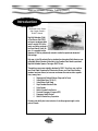
Welcome to the Canadian Coast Guard’s
RHIOT School.
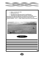
Rigid Hull Inflatables (RHIs),
or Fast Rescue Craft (FRCs)
as they are sometimes called,
assist in roughly 80% of the
search and rescue incidents in
the Coast Guard’s Pacific Region. It is essential that the
operators of RHIs be professionally trained to handle the operational demands of
their taskings.
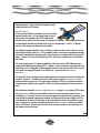
Each year, in the Fall and early Spring, students from throughout North America come
to Bamfield, British Columbia to take part in the Canadian Coast Guard’s specialized
Rigid Hull Inflatable Operator Training or RHIOT School.
The week-long course was originally developed in 1984. Since then, over one thousand Coast Guard, Department of Fisheries and Oceans, and Coast Guard Auxiliary
members have been trained, as have men and women from various other organizations, among them:
P
P
P
P
P
P
P
P
P
Department of National Defence (Navy and Air Force)
United States Navy (S.E.A.L.S.)
United States Coast Guard
Royal Canadian Mounted Police
Parks Canada
British Columbia Parks Service
Provincial Emergency Program (PEP)
Emergency Health Services
British Columbia Ferry Corporation
Our west coast facility also trains instructors for similar programs taught in other
parts of Canada.
7
Rigid Hull Inflatable Operator Training (RHIOT)
NOTES
8
Rigid Hull Inflatable Operator Training (RHIOT)
Unit 1
SAFETY
1-1 The Canadian Coast Guard Fleet Safety Manual
The Canadian Coast Guard’s Fleet Safety Manual outlines the policies on safe working practices within the
Coast Guard fleet.
Section 7.D.14 of this manual deals with the safe operation of small craft operated from Coast Guard
ships, small craft supported by Coast Guard ships (i.e. from other government organizations) or small
craft operated by Coast Guard shore-based units.
This unit outlines these rules. Refer to the Fleet Safety Manual for further details.
Roles and Responsibilities
Commanding Officer:
Responsible for the overall safe operation of small craft deployed from his/her ship or
station. Specific tasks are delegated to officers or crew, and should be outlined in the
vessel/station work instructions.
P Responsible for ensuring that small craft operators fully comply with the Canada Shipping
Act – Small Vessel Regulations and the Boating Restriction Regulations.
P
Small Craft Operator:
P
Responsible to the Commanding Officer for the safe operation of the craft entrusted to him/
her. He/she shall ensure that all appropriate safety precautions are followed, and report all
deficiencies and defects as soon as possible to the appropriate individual.
Procedures
9
Rigid Hull Inflatable Operator Training (RHIOT)
Training and Qualifications:
The Competency of Operators of Pleasure Yacht Regulations require that all operators of
small craft have an operator’s card appropriate to the type of craft operated. The Coast
Guard is not exempt from this requirement.
P Some barges and launches carried aboard Coast Guard ships, or operated from shore
bases, are larger than 10GRT. Operators of these vessels require formal marine certification
issued by Transport Canada or must have training and experience appropriate to the task,
area of operation and size of the craft, as recognized by the Coast Guard’s Fleet Technical
Training Section.
P A formal training course for Fast Rescue Craft (FRC) or Rigid Hull Inflatable (RHI) operations
must be satisfactorily completed by all personnel required to operate these vessels.
P Operators of Fast Rescue Craft/Rigid Hull Inflatables must demonstrate their ability to
achieve the standards established in performance objective 10 of the Search and Rescue
Training Standards (TP 9224).
P
Task Review and Risk Assessment
Prior to conducting small craft operations, the Commanding Officer or his/her designate must review the
required task and assess the risk based on the following factors:
P
P
P
P
P
P
P
What is the urgency of the task, and what are the consequences if it is not carried out or
delayed?
Is the selected small craft suitable for carrying out the task?
Is the small craft crew qualified and trained to carry out the task?
Have the required maintenance routines been carried out and are there any known defects
or deficiencies in the craft?
Can the craft be launched and recovered safely in the prevailing conditions?
What is the present and forecast weather?
Does the craft have the required safety, communications, and navigation equipment to carry
out the task safely?
Is the information on the required task reliable?
P
Operation Planning and Preparation
10
Rigid Hull Inflatable Operator Training (RHIOT)
The degree of planning for an operation will depend on the complexity of the operation, the type of small
craft, the training and experience of the crew, and the degree of risk identified. The following are minimum requirements that must be met to reduce identified risks:
P
P
P
P
P
P
P
P
P
Small Craft Crewing – Small craft must carry no fewer than two qualified crew members
other than when in sheltered waters where the small craft can be monitored visually from the
ship or station. All small craft operators shall be familiar with the craft they are operating by
having reviewed the particular small craft manuals, where available. At a minimum, operators should be familiar with:
♦ Craft systems and electronics (including the fuel system);
♦ Location and operation of safety equipment;
♦ Load capacity;
♦ Range at various speeds; and
♦ Seakeeping capabilities.
Familiarization and Maintenance Plans – Each small craft must carry and maintain a
Record of Operator Familiarization. Maintenance plans shall be developed by each Coast
Guard Region for each type of small craft utilized in that region.
Floatation – Each person on board the small craft will wear an approved Personal Floatation Device (PFD) or better, at all times while on board the craft. The type and style of PFD
will depend on the conditions present and the type of operation, however, operators should
plan for possible changes in conditions and prepare accordingly.
Protective Headwear – Small craft crews shall wear the appropriate type of approved
protective headwear at all times while the craft is in motion.
Footwear – Crewmembers will wear non-slip footwear appropriate for use on wet decks.
When conducting cargo operations, small craft crews shall wear approved safety footwear.
Thermal Protection – Where hypothermic conditions exist or are anticipated, small craft
crews shall wear approved-type Marine Anti-Exposure Deck Work Suits or dry suits. Where
dry suits are worn, a floatation device must be worn as well.
Eye Protection – Appropriate approved eye protection shall be worn based on prevailing
conditions.
Kill Switches – All FRCs/RHIs shall be fitted with a kill switch. Other boats may be fitted
with kill switches. Where kill switches are required or installed, operators shall have the kill
switch lanyard attached at all times while operating the motor(s).
Communications Schedule – A communications schedule will be established between
the ship/station and the small craft, based on prevailing conditions, type of operation and
11
Rigid Hull Inflatable Operator Training (RHIOT)
type of small craft. Procedures shall be identified for loss of communication or failing to
meet communications schedule. Standard communication schedules may be established in
vessel/station work instructions.
P Log Keeping – All small craft operations shall be logged as to the time departed the ship
or station and the return to the ship or station. Entries shall include the number of persons
on board.
Crew Briefing
The Commanding Officer shall ensure that small craft operators have been briefed on the planned operation, with particular attention paid to:
P
P
P
P
Present and forecast weather (for extended operations in time and/or distance);
Recommended routing;
Hazards enroute and in area of operation; and
Additional equipment requirements for the planned operation.
Small Craft Operators will provide an operations briefing to their crew as appropriate. Passengers and
non-trained personnel shall be provided with a safety briefing prior to departure. This briefing will, at a
minimum, include instructions on the proper wearing of floatation devices and the location of other safety
equipment.
Pre-Departure Checklist
A craft-specific check will be carried out prior to departure. This review will include critical equipment
checks, visual inspection and a successful communications check.
Launch and Recovery
Launch and recovery operations shall be carried out according to vessel-specific work instructions. The
12
Rigid Hull Inflatable Operator Training (RHIOT)
instructions shall be specific for the type of craft and/or launch/recovery arrangements. Work instructions
shall include, but not be limited to:
A procedure to ensure approval is received from the bridge prior to launch and recovery;
Designation of a crewmember as being in charge of the launch/recovery operation on deck;
and
P Establishment of a method of communication between the responsible person on deck, the
small craft, and the bridge.
P
P
Underway Operations
Small Craft Operators shall assess the conditions, both enroute and on-scene, to determine the adequacy
of the craft and crew to safely carry out the operation. Where it is assessed that the risk is too great, the
Operator shall advise the Commanding Officer and take appropriate action such as standing off, returning
to the ship/station, or seeking a suitable refuge. The Operator must pay particular attention when operating in areas of limited depth and/or high current, where there is possibility of the vessel being overturned
in surf or breaking seas.
Post-Operational Checks
Upon completion of each operation, a Post-Operational Checklist shall be completed. Maintenance
and repairs shall be carried out as soon as possible. A defect list shall be maintained for each craft,
along with a record of any repairs made.
Documentation
P
P
P
P
P
Ship-specific Checklists
Unit-specific Checklists
Training Records
Familiarization Records
Log Book Entries
Search and Rescue Policy Documents (Publications)
Vessel range, operating conditions and safety considerations must be in accordance with accepted Search
13
Rigid Hull Inflatable Operator Training (RHIOT)
and Rescue (SAR) standards as outlined in such publications as the National SAR Manual, MERSAR, etc.
Dispatch and Launch Factors
The following factors must be taken into consideration when the Commanding Officer or station Officer-inCharge decides whether or not to dispatch/launch an FRC:
P
P
P
P
P
Capability of the specific craft to carry out the mission in existing and anticipated sea and
weather conditions.
Experience level of the crew in the prevailing weather/sea conditions.
Likelihood of success vs. the possible danger to the crew.
Availability of back-up unit in case of emergency (i.e. another FRC or vessel, rescue helicopter, etc.).
Shipborne FRC – capability and operating range of launch/recovery system vs. sea conditions.
Mission Factors
The craft coxswain must consider the following factors before entering a hazardous situation or when encountering heavy weather after leaving the ship or station:
P
Situation and the adequacy of the boat and crew to complete the task safely –
the coxswain must stand off if the mission presents a serious safety risk to the crew;
P Available depth of water – keeping in mind the possibility of the craft being overturned
in the surf or breaking waves;
P Communication – keeping the OIC/CO informed at all times.
Safety Gear
Safety is of paramount importance. Each crew member will use safety gear that is appropriate for the ex-
14
Rigid Hull Inflatable Operator Training (RHIOT)
isting conditions. This equipment will include, at a minimum, the following:
Protective Headwear
P While involved in SAR operations, RHI/FRC crews must wear helmets that have been ap-
proved for use on FRCs. The helmet must be worn correctly, with the chinstrap snugly fastened;
P When engaged in non-SAR taskings, FRC crews must wear helmets when conditions warrant,
including wearing either FRC helmets or hardhats when working in the vicinity of overhead
loads or lifting equipment.
P Important – Hard hats should not be worn while the FRC is underway, other than when
maneuvring at slow speeds.
Thermal Protection
P Crewmembers must wear approved protective suits when the risk of hypothermia exists. Dry
suits must be worn with appropriate undergarments.
Personal Buoyancy Equipment
P FRC crews must wear an approved personal floatation device at all times. When wearing
vest-style PFDs, they must be securely fastened to the body with four (4) cinch straps
(2 per side).
Eye Protection
P To guard their eyes against sea spray, small dust particles, debris, UV rays, and to prevent
excessive tearing from the wind, crew members should wear eye protection whenever possible and practical. Eye protection must be approved to ANSIZ87.1-89 or equivalent.
Footwear
P Non-skid deck boots designed to provide maximum traction must be worn. If the crew is en-
gaged in cargo operations, then approved safety footwear must be worn.
Related Fleet Orders
P Coast Guard Fleet Order (CGFO) 535.00 – Rescue Specialists on Board CCG Ships. Coast
Guard Rescue Specialists must be trained in the operation of Fast Rescue Craft/Rigid Hull
Inflatables.
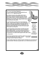
It is easy to forget how quickly the water can claim a life. It removes heat from our bodies 25 times faster
than air. Yet many victims do not even have the chance to get cold. The shock of the icy water causes
them to hyperventilate and their lungs fill with water after a minute or two. Professionals who work on the
water must be prepared for any eventuality. You can give yourself the survival advantage by wearing the
15
Rigid Hull Inflatable Operator Training (RHIOT)
right gear for the job. Remember, most drownings occur on nice days.
Safety equipment that doesn’t fit is dangerous. There are countless stories of people struggling to survive, only to be hampered by exposure coveralls that are too big, or a PFD that floats over their head.
Gear that doesn’t fit is uncomfortable to work in, and could cost you your life. If you are out in a boat on
a regular basis, get yourself a set of gear that fits – and wear it.
1-2 Getting The Right Gear For The Job
It’s easy to underestimate your needs when the sun is shining as you leave the dock. Conscientious crew
members organize their gear before they leave, and usually put it in a kit or equipment vest (worn over
top of a PFD). Safety equipment must provide you with five essential things:
P
P
P
P
P
Floatation
Warmth
Protection
Visibility
Mobility
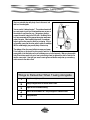
ò Floatation
A floatation device is essential when entering the water, either by accident or on purpose. It is designed
to provide enough floatation to minimize your need for excessive movement and to help you remain headup in the water. Although a PFD (Personal Floatation Device) does provide a specific amount of floatation, only a standard lifejacket will keep your head up without effort on your part.
ò Personal Floatation Devices (PFDs)
Transport Canada and General Standards Board-approved PFDs (CGSB 65-11-M88) must be worn by all
people on board Department of Fisheries and Oceans’ small craft while underway. It is important that
they are worn with straps and zippers fully fastened, and that the PFD is in good condition. Personal floa-
16
Rigid Hull Inflatable Operator Training (RHIOT)
tation devices are designed to offer padded protection to the front and back of the
body during high-speed operations, and their straps and buckles will stay fastened
on impact with the water. A snug fit and slim design gives the wearer comfort and
mobility to work. Unlike a standard life jacket, the PFD will not turn an unconscious victim upright in the water. The floatation foam used in PFDs will deteriorate after heavy use and exposure to the elements.
PFDs are available in many sizes and designs. The most important features are
that they fit properly, have enough floatation for your size when you are carrying
extra equipment, and that they have good straps and fasteners.
Transport Canada recently approved new colors, such as blue and purple, for use by recreational boaters.
Some of these colours are not as visible as the standard red, yellow and orange PFDs. Those who work
on the water usually choose the more visible colours to increase their survivability should they fall overboard.
ò Anti-Exposure Coveralls and Jackets
Anti-exposure coveralls (often referred to as floater suits) are a good choice for operations on the west
coast or in northern waters. The floater suit is one of the most common pieces of safety equipment used
by rescue personnel today because it offers warmth and protection, as well as pockets for carrying safety equipment. For sunny days, the floater jacket is a good choice
as a PFD. Some have a beaver tail that straps between your legs to protect your
groin area from heat loss. Both of these floatation garments offer at least 15 pounds
of positive buoyancy and some suits have inflated pillows for extra head support.
Floater suits must fit properly and be cinched when in the water. The cinch points are
at the ankles, knees, waist, wrists and neck. These cinches are to limit water circulation and must be tight when in the water. When you hit the water, cinch those straps
tight to increase your survival time.
Most anti-exposure coveralls and jackets are not waterproof and can deteriorate
rapidly if not properly washed and maintained. The foam floatation can break down
and become matted and lumpy after a few years of use. When this occurs, the suit
will no longer offer the positive buoyancy required to keep your head out of the water.
Suits and jackets that are worn often should be replaced when the material begins to
deteriorate.
17
Rigid Hull Inflatable Operator Training (RHIOT)
These garments will increase your survival time in cold water, but do not offer the
protection of a dry suit or a survival suit. The full exposure coveralls can also severely limit swimming and movement, especially if they don’t fit properly.
Any floater suit or jacket you wear must be Transport Canada and
General Standards-approved (CGSB CAN/CBSB 65-11 M88).
ò Warmth
Increase your
survival time in a
floater suit.
Remember to
cinch the ankles,
knees, waist,
wrists and neck
when you hit the
water.
Without thermal protection, most adults will die within the first two hours of exposure
in Canada’s frigid waters. To guard yourself against hypothermia during RHI/FRC operations, you must protect your high heat loss areas – head, neck, torso and
groin. Anti-exposure suits, dry suits or raingear can keep out the moisture, but you
also need insulation to stay warm. The best choices are materials made from polypropylene and wool.
P
Polypropylene is the material of choice – not only does it
NOTES
18
provide a great thermal
Rigid Hull Inflatable Operator Training (RHIOT)
layer, it can also wick the perspiration away from your skin, giving you
a dryer insulation from the cold.
P Wool is a good insulator, but does not wick moisture away from
the skin.
P Cotton is a very poor choice for clothing, since it wicks and
holds moisture against the skin, losing its thermal qualities as it becomes wetter.
P
P
P
When worn with other equipment, polypropylene liners will
provide the greatest amount of thermal insulation.
Do not wear cotton undergarments with a polypropylene
liner. It defeats the purpose of the polypropylene.
Layering is always the best approach, because it allows you to
High heat loss ar-
Cotton is a very
poor choice for
P A wool toque or polypropylene balaclava on the head, and clothing because
a scarf or polypropylene neck warmer can reduce heat loss it holds moisture
by up to 25%.
against your skin
and looses its
thermal qualities
as it becomes
The weather can change in minutes and you might be caught by surprise. Stay
wetter.
alive by bringing both cold weather and warm weather gear on warm days. Thermal
add or remove garments as necessary.
underwear (polypropylene or wool long johns) will help keep you warm. When
wearing a dry suit, you can don a fleece liner to provide excellent thermal insulation. It can be worn underneath a floater suit as well. When wearing a liner be sure not to have on any cotton clothing underneath, since the cotton will trap the cold water against your skin.
ò Survival Suits
A survival suit is truly the best thing to have on if you’re floating in cold water. It keeps you dry, is very
well insulated, and it floats you upright on your back while protecting your airway from the water. With big
floppy arms and feet and made from thick neoprene rubber, the survival suit is almost impossible to walk
or move in. It is designed for only one purpose – survival.
ò Dry Suits
The most effective way to keep warm is to stay dry. A lightweight dry suit offers the best balance of dry-
19
Rigid Hull Inflatable Operator Training (RHIOT)
ness and mobility in cold weather. It is ideal for extended missions in severe climactic
and oceanic conditions. The Department of Fisheries and Oceans’ dry suits are constructed of nylon polymer, similar to a diving dry suit, but use a thicker gauge material.
There is no valve on the suit, and they generally have reinforced knees, elbows and buttocks. Hoods are not attached, and the suit is worn with a thermal liner. Neoprene
seals are superior to the latex seals at the neck and hands. Some dry suits have integral work boots or soft-shoes. The latex in dry suits breaks down with exposure to UV
rays and petroleum stains. Always clean and store your dry suit properly after each
use.
ò Protection
Government vessels often operate in severe conditions. With frequent heavy impacts (up to 11 G force),
NOTES
20
Rigid Hull Inflatable Operator Training (RHIOT)
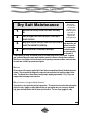
Dry Suit Maintenance
Remember Dry suits have
no inherent
floatation and
must always be
worn with a
PFD and the
appropriate
undergarments.
1
Wash and rinse the dry suit with fresh water after every
use.
2
Lubricate zippers with a silicone spray or hand soap to
prevent corrosion.
3
Hang up the dry suit and zip it closed to air dry in order to high wind chills, and
prevent the material from stretching.
excessive noise lev-
els, a crew member
can find himself in
4
an extremely hostile
environment. If
something does go wrong, the crew may be at risk from head injuries and/or blunt trauma. Protective
gear is essential when your vessel may be tasked to respond to a distress call under these conditions.
When there is the slightest risk that the vessel could be operating in extreme conditions, each crew member must wear a helmet, eye protection and gloves.
Wash out stains with a mild soap or detergent.
ò Helmet
All fast rescue craft crews are supplied with Coast Guard-recommended and General Standards-approved
helmets. They are specifically designed to reduce wind noise and protect the head from impact on four
sides. The helmets have a low profile and are light weight, weighing approximately 11.5g. They come
equipped with break-away straps and visors.
ò Eye Protection (Goggles/Safety Glasses)
Eye protection is vital, particularly during long operations. The eyes are the most vulnerable and sensitive
area of the body. Goggles or safety glasses protect your eyes against wind, rain, sea spray, ultraviolet
light, glare and small particles that are blown up from the deck. The lens of your goggles or safety
21
Rigid Hull Inflatable Operator Training (RHIOT)
glasses should be curved to shed water.
ò Hand Protection
A good pair of gloves is essential gear for both the vessel operator and crew. If the
operator or crew allow their hands to become cold, they lose the dexterity required
to perform their assigned tasks. Several types of gloves are available on the market.
quirements or preferences will dictate what you choose.
Individual re-
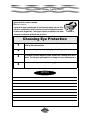
Choosing Eye Protection
1
Any device worn must have a safety lens capable of withstanding impacts while
providing UV and wind protection.
2
The lens must not impede your vision by fogging or obstructing peripheral vision.
3
Eye protection should be designed to prevent accidental loss or damage due to wind or
impacts. The best way to guard against loss or damage is to use a restraining strap or
4
If you use corrective eyewear, ensure that your goggles accommodates it.
NOTES
22
Rigid Hull Inflatable Operator Training (RHIOT)
P
Gore-Tex is good, but salt crystals will cut and destroy the fabric if it is
not constantly maintained.
P Wool provides warmth when wet, but will not protect you against the wind.
P Neoprene diving gloves fit too tightly, and reduce circulation.
P Rubber gardening gloves are inexpensive, but without a liner they’re cold.
Rubber reduces moisture loss from the skin and provides a good barrier
against the wind while preserving finger dexterity.
P
Remember, the more expensive glove is not necessarily the best.
ò Footwear
When your work involves handling heavy objects that could drop, you must wear protective footwear.
Footwear worn under these conditions must not only protect your toes, but the bridge of your foot as well.
Good safety footwear provides:
P
P
P
Steel toe cover
Cushioned bridge pad
Sole guard to prevent nail punctures.
With all these safeguards, the footwear can be too heavy or too cold to be worn comfortably. Not all operations require protection from injury, so the requirements for traction, warmth and comfort become
paramount. RHI crewmembers need a quality boot that provides good adhesion to the deck. A soft sole
deck boot or shoe provides good traction. The footwear must not be so tight as to restrict circulation. If
it does, then cold feet and cramps will occur.
ò Internal Organs
Internal organs can and will become damaged when operating in rough sea conditions. One way to protect yourself is by using a support belt. The belt should be wide enough to support the stomach and
lower back without restricting movement. The support belt is used to help contain the internal organs, not
allowing them to move around the stomach cavity causing bruising. Your must remember that if the belt
is worn too tightly, the bladder cannot fill properly, resulting in the need for frequent urination. Prolonged
use of a support belt will weaken stomach muscles.
23
Rigid Hull Inflatable Operator Training (RHIOT)
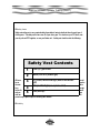
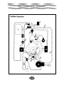
ò Safety Vests
Safety vests allow you to carry required safety items without having to duplicate them for each type of
clothing worn. The safety vest is worn over all of your other gear. It is used over your PFD alone, over
your dry suit and PFD together, or over your floater suit. A safety vest should contain the following:
Safety Vest Contents
1
Three (3) Type B flares
2
Whistle (Fox-40 or pealess type)
flash/minute strobe light (white strobe distress
All items
3 50-70
light)
be sethe vest
long
4 Waterproof flashlight (non-explosive rated)
lanyard to
Knife (blunt tip)
easy ac5
and use.
pocket snaps require frequent lubricating with Vaseline.
ò Visibility
24
should
cured to
with a
enough
permit
cess
The
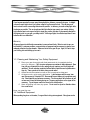
Rigid Hull Inflatable Operator Training (RHIOT)
Personal Rescue Equipment Vest
25
Rigid Hull Inflatable Operator Training (RHIOT)
If you become separated from your vessel during daylight or darkness, you need to be seen. In daylight
you need to wear bright colours (red, yellow, orange or any fluorescent colour). This will give you as
much contrast from the surrounding environment as possible. In darkness, you need as many light reflective devices as possible. This can be achieved with light reflective tape sewn to your exterior clothing.
Light reflective tape is not as good as light to signal your position, but when it’s permanently attached to
the highest points on your gear, you always have it. Unlike signal lights, the reflective tape doesn’t have
batteries which can malfunction.
ò Mobility
All personal gear should allow the crew member to move and work freely. When too much is worn you
lose flexibility. In extreme conditions, some restriction of movement may be necessary to give the crew
adequate protection from the elements. Make sure that all of the gear fits you. Again, it’s best to layer
your clothing, but avoid bulking up too much.
1-3 Cleaning and Maintaining Your Safety Equipment
P
Rinse your gear thoroughly with fresh water and dry it completely before
storing on hangers – Salt, corrosion and grease are enemies of safety equipment. Given
time, salt can cut material like a knife, making a dry suit a wet one, and a rain jacket well
ventilated. The salt molecules penetrate the fibres while in liquid form and crystallize when
they dry. These crystals cut the fabric during normal motion.
P
P
Grease should be washed out with a mild, non-abrasive detergent.
All zippers on dry suits require lubrication. Lube the zippers with bar soap, bees
wax, silicone spray or Protectant 303. Bees wax will have a tendency to trap abrasive particles. Clean frequently and replace as necessary. The other products will not adhere as well
as bees wax, but are self-cleaning during use. Frequency applications on the zipper will be
necessary. Dry suit zippers need to be stored in the closed position.
P Store all clothing in a clean, dry space. Do not crunch a dry suit or floatation device
into a small locker.
Keep your gear like new.
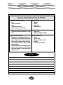
1-4 Additional Equipment
When spending long hours on the water, it’s a good idea to bring extra equipment. Extra gloves and an
26
Rigid Hull Inflatable Operator Training (RHIOT)
extra hat are always a good choice. High energy snacks, like granola bars or peanuts will get the crew
through long hours at night or long patrols. The list of items you could carry in your vest is endless.
Here are some suggestions:
Your Personal Equipment Kit
P
Knife
P
Light and Dark Eyewear
P
Note Pad
P
Checklists
P
Grease Pencil
P
Small First Aid Kit
P
Pen or Pencil
P
Toque or Balaclava
There’s P Gloves
no use
P Pen Light
having a
PFD
with 15 pounds of buoyancy if your equipment vest or other equipment weights 30
pounds!
COMMUNICATIONS
NOTES
27
Rigid Hull Inflatable Operator Training (RHIOT)
NOTES
28
Rigid Hull Inflatable Operator Training (RHIOT)
Unit 2
VESSEL SAFETY
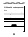
2-1 Daily Inspection Checklists
To remain shipshape, a working boat should be checked and maintained daily. A daily inspection should
be part of your team’s regular workday routine.
Your Daily Checklist (on the following page) should note any defects and the action taken to remedy
problems. Special attention should be given to safety equipment.
“Life Saving Vessels fulfill their function under
conditions which, for other craft and equipment,
are regarded as extreme—to be avoided, if possible.
Thus the concept of “Acceptable risk of failure”
cannot apply.
It is when other vessels have failed that
the life saving vessel must work.”
G. Klem, Senior Research Engineer
Norwegian Ship Research Institute
29
Rigid Hull Inflatable Operator Training (RHIOT)
Daily Inspection Checklist
Vessel License:
Floatation Device Per Person
Tube Pressure
Batteries
Electrical Connections
Oil Levels
Fuel Levels
Tow Assembly
Cage
Antennas
Capsize Reversal System
Personal Recovery Line
Knife
Radio Test
GPS
Radar
Sounder
Navigation Lights
Strobe
Instrument/Gauge Lights
Bilge Pump
Horn
Steering
Search Lights
Toolkit and Essential Spares
EPIRB
30
Rigid Hull Inflatable Operator Training (RHIOT)
Daily Inspection Checklist (continued)
De-water Void Spaces/Consoles
Sea Anchor
Anchor and Rode
Bailer/Manual Bilge Pump
DMB
Fire/Salvage Pump and Fuel
Buoyant Heaving Line
Paddles
Flares
First Aid Kit
Fire Extinguisher(s)
Tighten Bolts
Tilt/Trim
PORT/STARBOARD
/
/
/
/
/
Props/Skegs
PORT/STARBOARD
/
/
/
/
/
Engine HRS
PORT/STARBOARD
/
/
/
/
/
RPM at Idle
PORT/STARBOARD
/
/
/
/
/
Tell Tale
PORT/STARBOARD
/
/
/
/
/
Kill Switches
NOTES
31
Rigid Hull Inflatable Operator Training (RHIOT)
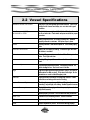
2-2 Vessel Specifications
Floatation Device Per Person
Everyone in the boating wearing a floatation device. Check to be
certain that all closures and straps, etc. are intact and in good
condition.
Tube Pressure (HARD)
240-280 MB or 4PSI
Check that tubes are rigid and fully inflated. Inflate from forward
to aft on both sides. Check valves and pressure reliefs for proper
operation.
Batteries
Wiring is tight and clean. No chafing of wiring runs. Batteries
properly secured in containers. Anti-siphon caps in place.
EPIRB
Securely fastened. Switched and taped off. Check battery expiry
date.
Electrical Connections
Wiring runs not chafing or binding. Connections tight and clean.
No breaks in insulation.
Oil Levels
Check by filling reservoirs, no matter how little. Check system for
leaks. Ports tight and clean.
Fuel Levels
Check by filling. Inspect lines and hoses for leaks and free movement.
Tow Assembly
Tow reel tightly attached to vessel. Line properly secured. No
visible damage to line. Reel is not loose in holders.
Cage
Cage and engine guard bar tightly bolted to vessel. No cracks or
deformations in welds or pipes. All structural bolts tight. No delaminations or cracks in metal/fiberglass joints.
Antennas
Tightly secured to mountings, including radar scanner. Coaxial
connections and wiring secure and not chafing.
Capsize Reversal System
Check bag for proper storage. Bottle and firing head secure in
mounting. Lanyard tight, not chafing. Handle clipped to transom.
Personal Recovery Line
Bag tightly laced to cage/guard bar. Line properly stowed and
bag closed properly.
Knife
Stowed properly in sheath. Not corroded and easily accessible.
Radio Test
Tested for rx/tx on working channel. Secure in brackets.
GPS
Acquires a position. Secure in mountings.
Radar
Proper acquisition of picture. All functions working properly.
32
Rigid Hull Inflatable Operator Training (RHIOT)
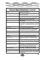
Vessel Specifications (continued)
Sounder
Proper function. Correct depth.
Navigation Lights/Strobe
All on and clearly visible. Switch works properly. Functions
properly. Securely mounted.
Instruments/Gauge Lights
Instruments functioning properly and readable. Gauge lights and
compass light working. Dimmer switch, if equipped, working.
Bilge Pump
Working in both the manual and automatic functions.
Horn
Functions properly.
Steering
Moves smoothly from hard-over to hard-over. Control cables and
wiring free moving. Connecting rod tightly secured. No excessive
wear in ball joints. No spongy movement in wheel or tight spots
in travel.
Search Lights
Each search light and each plug works properly.
Toolkit and Essential Spares
Toolkit complete and in good condition. Spare plugs and other
parts stowed in waterproof container and in good condition.
EPIRB
Secure in its bracket and switch taped off. Do not turn on to test.
De-Water Void Spaces/Consoles
Pump out void spaces. Dry out spaces under consoles and bowbox.
Sea Anchor
Material and bridle in good shape and properly attached.
Anchor and Rode
Anchor and rode in good repair. Shackles seized, correctly
stowed.
Bailer/Manual Bilge Pump
Correctly stowed. Functions properly.
DMB
Properly stowed and in good repair. Works correctly if electrical
type.
Fire/Salvage Pump and Fuel
Correctly stowed. Proper service and start-up and shut-down
procedures adhered to. Fuel stowed in proper container – not
leaking. Pump not damaging other contents of bowbox.
Buoyant Heaving Line
Proper stowage. Line in good repair. Easily accessible.
Paddles
Correct stowage. In good repair.
Flares
Check expiry date. Stowed in dry container. Check for sweating
and cracks in cases.
33
Rigid Hull Inflatable Operator Training (RHIOT)
Vessel Specifications (continued)
First Aid Kit
Correct stowage. Fully equipped. Dry. Easily accessible.
Fire Extinguisher(s)
Stowed securely in bracket. Easily accessible. Gauges show correct pressure. Container not excessively corroded.
Tighten Bolts
Periodic inspection of all exterior fasteners. Tighten as necessary.
Tilt/Trim
Full range of movement of engines with all trim controls. Moves
smoothly.
Props/Skegs
Inspect props/skegs/lower leg/ventilation plates for chips and
cracks. Retainers for props present and correct.
Engine HRS
Record and transfer to appropriate logbook.
RPM at Idle
Record neutral idle and in-gear idle and compare to manufacturer-recommended idle settings. Put in gear only when engines
are running.
Tell Tales
Forceful jet of water from back of engine. Does not get hot to the
touch after warm-up. Proper water pressure readings on gauges
if so equipped.
Kill Switches
After all warm-up procedures complete, kill switches stop engines
on removal. Replace and re-start. Engines re-start, run properly
and shut down correctly with key. Spare kill switch lanyards in
boat. Spare keys in boat.
34
Rigid Hull Inflatable Operator Training (RHIOT)
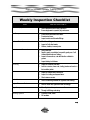
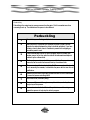
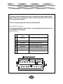
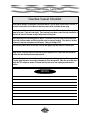
Weekly Inspection Checklist
ITEM
INSPECTION POINTS
Rescue Equipment
√ Check equipment listed in daily inspection.
√ Ensure equipment is operable, dry and secure.
Fire Pumps
√ Run up and flushed with fresh water.
√ Pressure test hose.
√ Inspect nozzles and threaded fittings.
Hull and Tube Connections
√ Check for chafing and wear.
√ Inspect all hull attachments.
√ Lifelines, handles, transom joints.
Batteries and Connections
√ Check fluid level.
√ Specific gravity, record data, low specific gravity over 1 cell
indicates deterioration of battery.
√ Inspect all connections, coat with Vaseline or dielectric
grease.
√ Inspect battery hold downs.
All Wiring
√ Inspect all terminals and wires.
√ Look for corrosion, loose nuts, chafing, breaks and cracks in
the insulation jacket.
Antennas
√ Inspect all coaxial cable connections.
√ Inspect for chafing and exposed wires.
√ Check antenna mounts.
Radio Mounts
√ Check all mounting hardware for tightness and cracking.
Engine Transom Bolts
√ Look for loose nuts, tighten and seal accordingly.
Bilge Pump
√ Manually test and inspect screens and hose.
√ Through hull fittings and wiring.
Steering System
√ Fluid level, rams, hoses.
√ All hardware.
35
Rigid Hull Inflatable Operator Training (RHIOT)
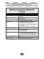
Weekly Inspection Checklist
(continued)
ITEM
INSPECTION POINTS
Hull
√ Inspect for cracks, gouges and delamination, clean hull at
this time.
Console
√ All bolts and nuts.
Seat
√ Seat hinges, tight and seal tears and cuts.
Towing Assembly
√ Check welds and fasteners for cracking and tightness.
√ Metals all subject to cracking and corrosion.
√ Hammer test for buzzing sound and indicating cracks and
loose fasteners.
√ Remove corrosion deposits and repair paint blisters.
Fuel System
√ Lines, filters, water separators, connections.
Zincs
√ Must have a good bond.
√ Change when at 50%.
All Grounds
√ Corrosion, loose nuts, deteriorated condition of wires.
√ Good clean grounds are essential for the proper operation of
engine components and functioning of sacrificial zincs.
All Grease Points
√ Refer to manual.
Lubricate All Linkages
√ Steering and throttle with dielectric grease.
36
Rigid Hull Inflatable Operator Training (RHIOT)
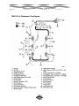
2-3 Fuelling
All government small craft should keep their fuel and oil tanks filled. This helps vessel stability and will
ensure that you have enough fuel in the event of unexpected delays. It also reduces condensation in the
tanks. It’s important to know your vessel’s fuel consumption and plan your trips accordingly.
Fuelling Instructions
1
NO SMOKING
2
Secure vessel to mooring.
3
Shut off main power.
4
Shut off bilge pump power.
5
Portable tanks ashore to fuel.
6
All passengers ashore.
7
Extinguish any open flames: stoves, BBQ’s, etc.
8
Use correct oil as indicated in the owner’s manual.
9
Ground nozzle before filling.
10
Fuel slowly to prevent spillage.
11
Wipe up any spillage.
12
Operate bilge blower before starting, to exhaust all bilge gasses.
13
Turn bilge pump back to auto.
37
Rigid Hull Inflatable Operator Training (RHIOT)
NOTES
38
Rigid Hull Inflatable Operator Training (RHIOT)
Unit 3
Wind, engine noise, the way seating is arranged, and motion all make communication aboard RHIs difficult.
But clear, effective communications are essential. Crew members must have all the information required
to work as a team. They must also understand and respond quickly to all orders or warnings.
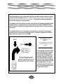
3-1 Closing the Loop
A ‘closed loop communications’ system is safe and efficient. It gives your crew a systematic approach to
communication, enabling them to work effectively as a team. Always be sure that you have heard
and understood the message and that what you have said is also understood. This form of
communications should be used for all operational communications both ashore and while underway.
Closed loop communications is achieved when you “get the SAC” - or when:
Closed Loop Communications
3-2
ings
S
SEND – the sender gives the information or command.
A
ACKNOWLEDGE – the receiver acknowledges by re-
C
CONFIRM – the sender confirms the acknowledgement. Brief-
peating key words or parts of the message.
39
Rigid Hull Inflatable Operator Training (RHIOT)
Always make time for pre-departure briefings. This gives the team a focus and an opportunity to develop
or modify plans before you get underway. A briefing should:
P
P
P
P
P
P
P
Present the plan or problem.
Outline the requirements and standards.
Identify weaknesses – welcoming questions and challenges.
Generate discussion – ask for questions/comments; strategize as a team.
Confirm the plan.
Define responsibilities and delegate the workload.
Detail the Pre-Departure Route Plan.
3-3 Debriefings
A debriefing should follow each mission. It may be as long or as short as required, but must be a whole
team effort – open and positive.
Debriefing Tips
Debrief as soon as is practical.
Start with yourself.
Discuss positive and negative, but always begin with a
positive.
Develop a plan for improvement.
Ask for questions and comments.
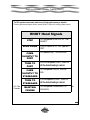
3-4 Hand Signals
40
Rigid Hull Inflatable Operator Training (RHIOT)
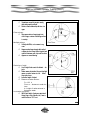
The RHI’s operational environment makes the use of hand signals necessary or desirable.
These simple hand signals will be used at RHIOT School for relaying helm orders:
RHIOT Hand Signals
STOP
TAP the operator on the TOP OF THE
HELMET.
SLOW DOWN PULL on the BACK OF THE operator’s
VEST.
TAP operator’s LEFT SHOULDER.
COME
SLIGHTLY TO
PORT
TURN TO
PORT
PULL on the operator’s LEFT SLEEVE
until the desired heading is reached.
TAP the operator’s RIGHT SHOULCOME
SLIGHTLY TO DER.
STARBOARD
PULL the operator’s RIGHT SLEEVE
TURN TO
STARBOARD until the desired heading is reached.
3-5 RaCommu-
MAINTAIN
COURSE
TAP the operator in the MIDDLE OF
THE BACK.
41
dio
Rigid Hull Inflatable Operator Training (RHIOT)
nications
A MAYDAY is used only in situations of grave and imminent danger. In a distress situation, vessels that
hear the MAYDAY call must render assistance if it is needed and they are capable of assisting without undue risk.
A MAYDAY message should be sent on the VHF Channel 16. You can also use a cellular telephone to issue a MAYDAY if you are on the coast. Dial *311 for a direct line to the Rescue Coordination Centre
(RCC).
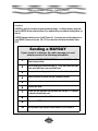
Sending a MAYDAY
If your vessel is in distress, the radio message you send
should consist of the following information:
1
Say the words MAYDAY, MAYDAY, MAYDAY (3 times) on VHF-FM Channel 16.
Speak clearly and slowly.
2
Give the name of your vessel three times, i.e. “This is motor vessel Wall Flower,
motor vessel Wall Flower, motor vessel Wall Flower.”
3
Give your position, with geographical references and coordinates, if possible.
4
State the nature of the distress and type of assistance required.
5
Give the number of persons on board and vessels involved, and any injuries.
6
Describe your vessel.
7
Provide any other information that could assist your rescuers, i.e. “Preparing
to abandon ship with floater suits.”
8
Maintain radio contact on Channel 16.
9
Repeat your MAYDAY until someone answers.
10
Use any means at your disposal to attract attention on VHF Channel 16.
42
Rigid Hull Inflatable Operator Training (RHIOT)
Recognized Marine Distress Signals
Canadian Modifications:
Strobe 50/70 (White) and Square Shape
NOTES
43
Rigid Hull Inflatable Operator Training (RHIOT)
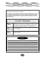
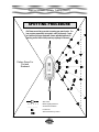
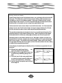
3-6 Scene Assessment and Crew Safety
You can expect to confront a variety of risks on the water. Whenever a small team arrives on scene, they
are compelled to get involved and help quickly. The sense of urgency can draw people into situations
before they are ready to deal with them. It’s important that you take the time to Stop, Assess and Plan
your course of action.
The SAP 100 Method
Stop
STOP outside of the event zone (approximately 100 feet
away from the incident scene, depending on the event type
and visibility). Person in Water = 100’; Vessel Afire = ?’
Assess
Crew members observe the scene, reporting their findings
to the unit leader.
Plan
Crew provides planning input to the leader, who determines
the plan of action.
NOTES
44
Rigid Hull Inflatable Operator Training (RHIOT)
Unit 4
EMERGENCY PROCEDURES
The emergency procedures outlined here are those used at RHIOT School. Refer to the Emergency
Procedures Section of your unit’s Standing Orders for emergency information specific to your operational environment.
The onboard emergencies covered in this unit are:
P
P
P
P
P
P
Man overboard
Person lost
Fire on board
Overturned boat/capsize reversal
Injured crew member
Vessel lost or disoriented
These are the procedures followed at RHIOT School. Again, students are asked to refer to their unit’s
Standing Orders. If there are no standing orders or established emergency routines for your unit, these
procedures would be good place to start.
4-1 Man Overboard
P
P
P
P
Post a lookout.
Keep the person in sight at all times.
Point at the person.
Follow the Man Overboard drill.
45
Rigid Hull Inflatable Operator Training (RHIOT)
4-2 Person Lost
P
P
P
P
P
P
P
Issue a PAN call on Channel 16.
Mark the last known position.
Gather all boats in the group together.
Commence an Expanding Square or Sector Search using all units.
Keep the Rescue Coordination Centre informed of the situation.
Cancel the PAN when the situation is resolved.
PAN can may have to be upgraded to a MAYDAY if situation worsens.
4-3 Fire On Board
P
P
P
Locate the source of the fire
Deploy a fire extinguisher or jettison the burning material
If unable to control the fire:
♦ Issue a MAYDAY on Channel 16 and activate EPIRB.
♦ Abandon the boat into another group vessel, if available.
♦ Cancel MAYDAY when the situation is resolved.
4-4 Overturned Boat / Capsize Reversal
NOTES
46
Rigid Hull Inflatable Operator Training (RHIOT)
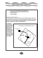
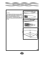
A variety of factors can cause a rigid hull inflatable to capsize.
1. If a breaking wave is taken on the beam, the RHI will lay on its side, causing it to ride on the
sponson. There is a good chance that the RHI may not capsize, but will just surf
on the sponson. But the RHI does stand a chance of capsize.
Breaking waves
2. If the RHI is laying head into the sea with little or no power on and is hit
taken on the
beam or head on
with a large breaking wave, there is a good chance that it will be pushed
backwards down the wave. The stern will stop once it bottoms out on the wave. can capsize an
RHI.
This will cause the bow to pass the stern, causing a capsize. This style of capsize is very real, violent and dangerous.
3. When heading into the wind in winds in excess of 60 knots , the RHI
when may be blown over backwards if the vessel is operated improperly.
4. If the RHI is being operated in 60 knots of wind and higher, there is a good chance the vessel
will be blown over (depending on how it’s loaded and the style of RHI). The solution is to quarter the
waves and the wind. This way, if a capsize does result, there’s a good possibility that the crew will be
thrown clear.
5. If the RHI is travelling down the face of a large wave, the forward portion of the sponson could
dig in and decelerate the bow, allowing the stern to pass the bow. This generally results in a pitch
pole style of capsize. When this happens, the bow will usually shear off, catching more water, slowing
down the bow even more.
If you’re onboard another group boat and you witness a capsize:
Notify base or MCTS Tofino of overturn.
Assist the persons in the water.
When all persons are safe, attempt to salvage the boat.
The coxswain of the second boat should take charge of the salvage operation, as the crew of
the overturned boat may be suffering from injuries or be shaken and/or disoriented by the
incident.
P Do not deactivate the EPIRB until secure at base and crew/vessel are secured in a safe
location. The EPIRB provides position reference DF to assisting vessels and aircraft.
P Advise the base or MCTS that the situation is still under control, of if you require any other
assistance.
P
P
P
P
4-5 Injured Crewmember
P
P
The crewmember with the best first aid skills should assess the injury.
Advise RCC of the injury through MCTS and request medical assistance if necessary.
47
Rigid Hull Inflatable Operator Training (RHIOT)
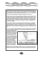
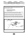
Capsize Reversal Training
The following steps will be demonstrated during RHIOT.
If your vessel has overturned:
1
Check crew for injuries and confirm the number of persons on board (POB).
2
All crew to assemble at the transom.
3
First crew member deploys the safety line and swims it out the complete distance (length of line). Remaining crew assist with deployment of safety line,
then follow the line out themselves. The coxswain remains at the transom.
4
After the crew are safely out of the way, the coxswain activates the capsize
reversal system by pulling firmly on the handle. As soon as the system is
activated, the coxswain will swim/pull himself down the safety line and out of
the way. See photograph below.
5
If the capsize reversal system is operating properly, it should take approximately 7 seconds for the vessel to right itself.
6
After the vessel has righted itself, the crew can begin boarding. Use the
windward side of the vessel. Do not try to climb over the engines – it’s dangerous!
48
Rigid Hull Inflatable Operator Training (RHIOT)
Capsize Reversal Training
The following steps will be demonstrated during RHIOT.
If your vessel has overturned:
7
After the crew are onboard:
P Check your crew for injuries and numbers.
P Test your radio.
P If no radio contact, activate EPIRB.
P Deploy the sea anchor.
P Recover the safety line.
P Remember that you do have flares, but use them wisely.
P In all probability, the engines will have water in the cylinders. The way to get the water
out is by removing the spark plugs and turning over the engine until all of the water is
gone. Replace the plugs and prime the fuel line, then try to start the engines.
P REMEMBER: Since the engines will have water in the carbs and cylinders (from the
exhaust system), you will have to turn them over for approx. 10-20 seconds. Water will
spray out of the spark plug holes. Once the engine is able to turn over without water
spraying out, pump the FUEL priming bulb to prime the carbs. DO NOT PRIME THE OIL
SYSTEM. If the starter is unserviceable, use the pull start method. Remember to activate the primer and turn on the key when it’s time to start the engine.
NOTES
49
Rigid Hull Inflatable Operator Training (RHIOT)
Provide first aid using the best available advice. If necessary, obtain an opinion through the
MCTS.
P Take the patient to the base or a rendezvous with an ambulance or doctor using the most
appropriate route.
P
4-6 Vessel Lost/Disoriented
Don’t compound the problem with an attack of ego.
Confer with the rest of the crew – maybe someone knows where you are.
Advise the base of your predicament and give them your last known position (they will dispatch a vessel to DF and find you).
P MCTS has surveillance radars and VHF DF equipment and may be able to help you.
P
P
P
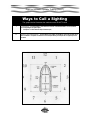
4-7 Recovering People From The Water
When approaching a person in the water consider the following:
NOTES
50
Rigid Hull Inflatable Operator Training (RHIOT)
P
P
P
P
Wind
Current
The RHI’s configuration
The style of lift that you’re going to use.
Approach into the prevailing environmental effect – wind or current, i.e. from downwind or into
the current, whichever affects your vessel the most. This gives you optimal control over your vessel and
makes it possible to drift away from the person in the water in the event that you are forced to abort your
approach. Wind has a greater effect on the boat than it does on a person in the water. If you must abort
an approach in a current situation, the positions remain static.
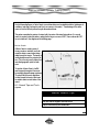
When approaching an overturned
sailboat or fishing
vessel, watch for
lines in the water.
Go
Approach from
downwind, as
lines drag
upwind.
Survivor
Wind
slow.
Remember
to have
someone
pointing to the
survivor at all times, calling out distances. The crew member pointing
should keep his/her arm moving at all
times. If they stop, there is a good
chance that they will lose sight of the
person.
Initial Approach
Turning Into the Wind
When approaching overturned sailing
vessels and/or fishing vessels, watch
for lines in the water. Approach from
downwind, as lines drag upwind.
The final approach should start 10-20
51
Rigid Hull Inflatable Operator Training (RHIOT)
metres downwind from the victim (further away if wind and sea conditions dictate) to ensure that the bow
is kept up into the wind. Again, go slow. The cardinal rule stressed at RHIOT is if the coxswain
can’t see the victim, the engines go into neutral. If the approach is aborted, the wind will blow
the boat off and the approach can be restarted.
The coxswain must have enough way on the boat so that when the victim disappears from sight below the
sponson (pontoon), the engines can be put into neutral and the boat turned to STARBOARD. Why starboard? Because our boats have the throttles positioned on the starboard side, so the port side is accessible for work.
The wind will assist the turn, once the coxswain has initiated the turn to starboard. Most unpowered
boats will want to lie across the wind and this helps the turn. The ideal rescue position for the victim is
directly abeam the coxswain’s seat on the UPWIND.
The cardinal rule at
RHIOT:
Wind
If the coxswain can’t see the
victim, the engines go into
neutral.
Victim
Final Approach
Notice that the boat is
downwind from victim.
52
The crew member responsible for sighting and calling distances must remember to continue indicating position
even after the victim disappears from
sight under the sponson. This keeps
the coxswain informed of the status of
the rescue. Get a hold on the victim as
quickly as possible because the RHI will
drift downwind rapidly. The person
pointing must keep his/her eyes on the
victim, even if it’s necessary for the RHI
to make another approach.
Rigid Hull Inflatable Operator Training (RHIOT)
Recovering a Victim
1
When recovering the victim, move him/her gently, as severe hypothermia can
quickly become cardiac arrest with rough handling.
2
Support the victim’s head at all times.
3
Talk to the person and reassure him/her. Always assume that the victim can
hear you.
4
Keep the victim on the upwind side of the boat. This will allow the victim’s feet
to act as a drogue, reducing the friction and effort required to drag him/her up
over the sponson. If the victim is on the downwind side, the feet are pushed
under the sponson, greatly increasing the effort required to lift.
5
Place the victim in the position of most comfort and as protected from the elements as possible.
6
Treat for hypothermia and administer first aid as necessary.
At RHIOT School, one and two person lifts are practised. These are the one and two person “snatch and
grab” lifts, as well as the two person parbuckling lift. This is the easiest method, but somewhat more
time-consuming. Steps and tips for each of these lifts are
described on the following pages.
With the exception of parbuckling, the victim is always
brought up facing the sponson, to avoid hyperextending the
back. With all lifts, the crew member grabs the victim by the
clothing, not by the PFD. If grabbed by the PFD, the victim
can slide out of it.
Whenever possible, use a line under the victim’s
arms and around the back. Be sure to keep your
centre of mass inside the RHI.
53
Rigid Hull Inflatable Operator Training (RHIOT)
One Person Lift
1
Once you have control of the person, place a short piece of line under his/her
arms.
2
Reassure the person.
3
Keep one knee up on the sponson.
4
Protect your own back.
5
Check to make sure that the coxswain’s seat is directly behind you.
6
Hold the line with both hands, as close to the person’s chest as possible.
7
Bob him/her a few times and then pull straight up until the person’s hips are
at the top of the sponson, then continue the dragging motion as you sit down
in the coxswain’s seat.
8
The person will be face down in your lap, across the sponson, with his/her feet
in the water.
9
Together with another crew member, pivot the person so that he/she is
for’n’aft along the sponson.
10
With a controlled lift and roll, place the person gently onto the deck.
54
Rigid Hull Inflatable Operator Training (RHIOT)
NOTES
55
Rigid Hull Inflatable Operator Training (RHIOT)
Two Person Lifts
Two person lifts are the same as a one person lift, except you have a crew member helping you with the
lift process itself. The crew member gains control of the person, then the coxswain or another crew member assists. The person forward, who will eventually have the head of the victim, controls the lift.
Two Person Lift
1
The forward crew member gains control of the person, and places a short
piece of line under his/her arms.
2
The forward crew member talks to the aft crew member as well as the victim
and reassures the person throughout the process. Communication is key.
3
The forward crew member must be abeam of the coxswain’s seat, and should
check to ensure there are no hazards behind.
4
Each of the two crew members should have one knee up on the sponson.
5
Both crew members hold the line with both hands, as close to the person’s
chest as possible
6
Bob him/her a few times and then pull straight up until the person’s hips are
at the top of the sponson, then continue the dragging motion as the forward
crew member sits down in the coxswain’s seat. The aft crew member lets go
of the line as the forward crew member sits down in the coxswain’s seat.
7
The person will be face down in the forward crew member’s lap, across the
sponson, with his/her feet in the water.
8
Together with the aft crew member, pivot the person so that he/she is for’n’aft
along the sponson.
9
With a controlled lift and roll, place the victim gently onto the deck.
56
Rigid Hull Inflatable Operator Training (RHIOT)
NOTES
57
Rigid Hull Inflatable Operator Training (RHIOT)
Parbuckling
Parbuckling is the easiest way to remove someone from the water. But it’s somewhat more timeconsuming to set up. The orientation of the person is also different.
Parbuckling
1
Start with the person floating on his/her back.
2
Attach two lines to the lifelines, one opposite the person’s knees, and one
opposite the midpoint between the person’s shoulder and elbow. If you have
to make a choice, attach closer to the elbow to prevent the line slipping up
around the person’s neck.
3
The aft crew member controls the victim alongside, while the forward crew
member passes his/her line under the victim at the aforementioned midpoint
and back up the outboard side.
4
The forward crew member controls the person, while the aft crew member
passes his/her line under the knees and back up the outboard side.
5
The crew member at the head controls the lift. The crew member at the head
is not necessarily the coxswain, but should be the person with the best first aid
qualification.
6
Reassure the person and continually communicate with the other crew member
if you are the person controlling the lift.
7
Give a three count, then start pulling.
8
The person will be carried through one complete rotation, and end up face-up
lying on top of the sponson.
9
Crew members involved in the lift should keep their knees and lower legs
against the sponson to help stop the victim’s progress.
58
Rigid Hull Inflatable Operator Training (RHIOT)
This lift method gives the crew a 2:1 mechanical advantage. Parbuckling is particularly useful
for extracting large people from the water, and it’s easier than it looks.
59
Rigid Hull Inflatable Operator Training (RHIOT)
Lifts in Review
1
Move the victim gently and protect the head.
2
Grab by the clothing, not the PFD.
3
Place a short piece of line under the arms and around the back of the person.
3
Bob the person to gain momentum before the lift.
4
Reassure the person at all times and communicate with other crew members.
Assume the victim can hear you.
5
Deflation of the tubes to facilitate lifts is not recommended. The person can
become trapped in the folds. Deflation also compromises the integrity of the
RHI.
6
The parbuckling lines may be pre-set prior to arrival on-scene to speed up the
rescue process.
7
The engines must go to neutral when the coxswain can’t see the person any
longer.
NOTES
60
Rigid Hull Inflatable Operator Training (RHIOT)
Unit 5
WAVES AND CURRENT
A competent seaman must have a solid understanding and appreciation of how waves work. By understanding how waves form, how they behave at sea, over shoals and in the surf zone, the seaman knows
what to expect and how to avoid or minimize danger to his vessel and crew.
The following definitions will assist in understanding the material covered in this unit.
5-1 Glossary of Wave Terms
Breaker – A single breaking wave, either of the plunging type or the spilling type.
Breaker Line – The outer limit of the surf. All breakers may not present themselves in a line. Breakers
can occur outside of the breaker line and seem to come from nowhere.
Comber – A wave on the point of breaking. A comber has a thin line of white water on its crest, referred
to as “feathering”.
Crest – The top of a wave, breaker, or swell.
Cycloidal Wave—Short steep waves breaking or about to break.
Fetch – The unobstructed distance over which the wind blows across the surface of the water.
Foam Crest – Top of the foaming water that speeds toward the beach after the wave has broken,
popularly known as white water.
Frequency – The number of crests passing a fixed point in a given time.
Interference – Waves that have been refracted or reflected can interact with each other as well as with
the incoming waves, and may be additive or subtractive, resulting in unnaturally high waves. Interference may even result in standing wave patterns (waves that consistently appear to peak at the same
spot). It can be of particular concern because it may result in a boat being subjected to waves from
unexpected directions and of unexpected size.
Period – The time it takes for two successive crests to pass a fixed point.
Series – A group of waves that seem to travel together, at about the same speed.
Surf – A number of breakers in a continuous line.
Surf Zone – The area near shore in which breaking occurs continuously in various intensities.
Swell – Waves that have moved out of the area in which they were spawned. The crests have become
lower, more rounded and symmetrical. In this form, they can travel for thousands of miles across
deep water without much loss of energy.
Tricoidal Wave—Ocean swell containing no net partical motion.
61
Rigid Hull Inflatable Operator Training (RHIOT)
Trough – The valley between waves.
Wave – A periodic disturbance of the sea’s surface, caused by wind, earthquakes, and the gravitational
pull of the moon and the sun.
Wave Gradient – The slope or angle of a wave from its trough to its crest.
Wave Height – The height from the bottom of a wave’s trough to the top of its crest.
Wavelength – The distance from one wave crest to the next, in the same wave group or series.
Wave Reflection – Almost any obstacle can reflect part of a wave, including underwater barriers such
as submerged reefs or bars, even though the main waves may seem to pass over them without
change. Reflected waves move back towards the incoming waves. When the obstacles are vertical or
nearly so, the waves may be reflected in their entirety.
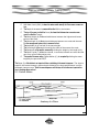
Wave Refraction – Refraction means bending. Wave refraction occurs when the wave moves into
shoaling water, interacts with the bottom and slows down. Naturally, the first part of the wave encountering the shallows slows down first, causing the crest of the waves to bend forward toward the shallower
water. The key to the am ount of refraction that occurs is the bottom terrain. Refraction can also occur
when a wave passes around a point of land, jetty, or island.
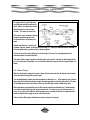
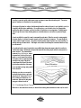
5-2 Wave Energy
Waves are the visible result of an energy transfer process. Usually caused by wind or the movement of a
vessel, this energy is transferred from these sources through the water until it is eventually dispersed and
decayed as breaking waves, or transferred to the shore as surf.
When waves are formed, certain forces immediately begin to act to bring the water’s surface back to a
level state. These forces are:
P
P
P
Gravity – which forces the wave to flow back down to a flattened position;
Surface Tension – which resists wave formation; and
Elasticity – which resists any changes in the total volume of the water.
If the force that caused the wave to form is removed, the water’s surface will eventually return to level as
a result of internal friction, because the energy has been transferred to another medium, such as floating
objects or the shore.
The Anatomy of a Wave
62
Rigid Hull Inflatable Operator Training (RHIOT)
P
P
P
P
P
P
P
P
P
P
Still Water Level (SWL) is where the water would naturally lie if there were no wave mo-
tion.
The Depth of the water is measured from the SWL to the bottom.
The top of the wave is called the Crest; the lowest level between two successive wave
crests is called the Trough.
The Wave Height (H) is the vertical distance between the highest and lowest
points of the wave.
The Wavelength (L) is the horizontal distance between one crest and the next .
For the average wave system, this is measured in feet.
The Amplitude (A) is one-half of the wave height.
The Crest Angle is the angle formed by the sides of the wave at the crest .
The Steepness of the wave is measured by dividing the height by the length (H/L).
The Wave Period (T) is the time interval, in seconds, between one crest and the
next, from a fixed observation point.
The speed of the wave motion, Phase Motion (C), is computed by dividing the wavelength by the period or C=L/T.
The Slope (S) of the bottom is an important factor contributing to the wave’s steepness. The slope is
equal to the vertical change in bottom depth divided by the horizontal distance in which
the depth change occurs. Both the wave steepness and the slope of the bottom are important fac-
tors in breaking waves and surf.
5-3 Particle Motion
Anatomy of a Wave
63
Rigid Hull Inflatable Operator Training (RHIOT)
As a wave travels through deep water,
very little water actually moves any distance. Rather, the motion which occurs
within the wave is circular in shape
(orbital). This motion is shown here.
At the wave’s crest, the water is moving
forward at a maximum speed in the
horizontal direction of the wave’s progress.
Halfway down the face, on the front of
the wave, motion is upward. At the bottom of the trough, it is moving at a maximum speed, backward, in
the horizontal direction opposite that of the wave’s progress.
On the rear face of the wave, halfway up from the trough to the crest, it is moving downward, at its
maximum speed in the vertical direction.
This motion allows a wave to approach a floating object, pass under it, and move on while leaving the object in the same place. Remember, it is current and/or wind which moves an object through the water, not
waves.
5-4 Wave Shape
When the wind imparts energy to the ocean surface, what the waves look like will depend on the strength
of the wind and how long it acts upon the water.
The unimpeded length of water over which wind blows is called the fetch. If this happens to be a lake ten
miles long, and the wind blows down its length, the waves generated on the lake have a fetch of 10 miles.
If the wind blows across the same lake, and it’s only five miles wide, the fetch would be five miles.
When wind waves are generated at sea, the fetch may be several thousand miles long. Sea wind waves
can receive tremendous energy and grow to immense size. If a large storm, such as a hurricane or typhoon, is the source of the wind, the resulting waves can be enormous and travel for long distances before they dissipate their energy as surf on some distant shore.
There are three distinct types of wind waves of major interest to the mariner:
64
Rigid Hull Inflatable Operator Training (RHIOT)
P
Deep Water Wave – When the depth of the water is greater than about one-third the
wavelength, the bottom has little effect on the wave, and it is called a deep water wave.
P Shallow Water Wave – When the depth of the water is less than one eleventh of the
wavelength, it is termed a shallow water wave, and is strongly affected by the bottom.
P Intermediate Wave – Between deep water and shallow water waves is a third type of
wave. Intermediate waves are hard to describe and beyond the scope of this manual.
As the wind continues to affect a deep water wave, it will grow until its steepness and crest angle approach a critical state. At this point, the wave becomes unstable and breaks. These storm tossed and
breaking waves are called Seas while they are still being generated. Deep water waves originating far
out at sea may have wavelengths of hundreds or thousands of feet, periods of many seconds, and may be
moving many tens of feet per second.
After deep water waves are generated far out at sea, they move outward, away from their wind source in
ever-increasing curves, and become what is called Swells. The farther the swell moves from its source,
the more uniform its characteristics become. It travels in a series of waves, relatively equidistant and
moving at a more or less constant speed. Swells generated from storms far out at sea are smoother and
more uniform than those which have recently originated nearby, which are more peaked and irregular.
The usual period of these swells is from six to 10 seconds. This corresponds with wavelengths of 184 to
1310 feet and velocities of 18 to 49 knots.
Interference between different swell systems traveling in nearly the same direction causes groups of
waves to travel outward in patches. As these wave groups (normally 7-12) move outward, the waves in
the front disappear, and new waves with the same characteristics appear in the back of the patch. This
process continues until the waves dissipate their energy at sea, or transfer it to the shore as surf.
Knowledge of the characteristic grouping of waves into groups is useful when operating in shoaling water
such as bars, inlets, or when working in surf. Wave groups can be observed and their group periods determined. Boats can be best maneuvered in the space between groups, when wave motion is at a minimum.
When deep water waves move into shallow waters, they are influenced by the bottom and become shallow
water waves. Wave speed decreases as they approach shore and interact with the bottom. The decreased speed causes wave refraction, thereby shortening the wavelength. As wavelength decreases,
wave steepness increases, and the wave becomes less stable.
As the wave moves into water where the depth is approximately twice the wave’s height, the crest peaks
up – the rounded crest of a swell becomes a higher more pointed mass of water with steeper sides. This
65
Rigid Hull Inflatable Operator Training (RHIOT)
change of wave form becomes more pronounced as the wave moves farther into shallow water. These
changes in wavelength and steepness occur before breaking.
Finally, at a depth roughly equal to 1.3 times the wave height (the actual formula used to determine when
the wave will break is when the height is equal to 80% of the depth ratio, H=.8 d), the wave becomes
unstable. This happens when not enough water is available in the shallow area ahead to complete the
crest and the wave’s symmetrical form. The top of the onrushing crest is left unsupported and collapses.
The wave breaks, resulting in surf.
The motion of the water in shallow water waves is no longer circular, but tends to become elliptical. Unlike
the orbital motion of deep water waves, these orbits do not decay with depth. The orbital motion of shal-
low water waves is shown below.
5-5 Breaking Waves
There are many degrees of intensity with breaking waves, depending on the deep water steepness of the
66
Rigid Hull Inflatable Operator Training (RHIOT)
incoming wave and the slope of the beach or shoal area. Over very gradual slopes, the wave begins to
break in a gentle Spilling action that dissipates just enough energy to keep the “80% of the depth” ratio
constant as the wave moves toward the shore or over the shoal. This spilling action is characterized by
white water at the crest of the wave. It is the beginning of the phenomenon called surf. The area near
shore in which breaking occurs continuously in various intensities is called the Surf Zone.
As the underwater slopes become steeper, breaking becomes more intense, and fewer waves break simultaneously. Waves begin to curl as the orbital speeds of the individual water particles at the crest increase with the increasing wave height. When not enough water is available to fill in the crest and complete a symmetrical wave form in the water ahead of the wave, the top of the onrushing crest is unsupported and
plunges ahead as an incomplete orbit.
This type of breaking is called Plunging. In plunging surf, only one wave
breaks at a time, and its intensity is
greatly increased by the backwash of the
wave that broke before it. Obviously,
this is no place to operate a boat. Remember, water is heavy, approximately
one ton per cubic yard. A breaking wave
could dump tons of water on you,
swam ping and/or severely damaging
your boat.
When the beach slope exceeds the wave
steepness, the breaker builds up as if to
form a plunging breaker, but the base of
the wave surges up on the beach before
the crest can plunge forward. This form
of breaker is called Surging. When the
depth ratio approaches about 1.2 (that
is, I/d = 1.2), the limit of breaking at the
67
Rigid Hull Inflatable Operator Training (RHIOT)
shoreline is reached, and all similar waves surge up steeper slopes without breaking at all. The various
types of breakers are illustrated on the previous page.
If the slope of the beach is uniform, the tide would move the entire surf zone in (on a high tide) or out (on
a low tide) with little other modification. On an offshore bar, or an inlet with a bar, the changing tide
modifies the depth of the water, and thus the effect of the bottom on incoming waves. Breaking waves
and surf may form over these shoaling waters on a low tide where no such action is present at higher
tides.
Current can affect the speed of a wave’s movement through water. When the current is moving against
the wave direction, it reduces the wave’s speed, and thus increases its steepness. The wave length decreases and the height increases. The result is breaking waves where they were not occurring before, or
making existing surf more violent. Tidal height and currents should always be considered when surf may
be encountered.
As mentioned earlier, wave characteristics are modified when deep water waves make the transition to
shallow water waves. Wavelength and speed decrease with decreasing depth, while the wave period remains constant. This phenomenal is
known as Wave Refraction, where
the wave front (the line of the crest)
bends or curves toward the shallows.
If the wave crests are approaching the
shoreline at an angle, they will be
curved toward the slope of the beach
Wave Refraction
by the bottom refraction of the wave
front, eventually arriving nearly parallel
to the shoreline.
Refraction can also occur around islands with sloping shores, and cause
wave fronts to “wrap around” the island, creating a shadow zone, confused seas, and even focusing wave
energy at a distant shoreline.
5-6 Combining Wave Fronts
When two or more wave fronts interact, or when a faster moving wave overtakes a slower one, the result-
68
Rigid Hull Inflatable Operator Training (RHIOT)
ing effect is called Interference. The water in each of these waves is moving in the same direction at the
point of interaction. The motion adds constructively and results in an increase in the wave motion at that
point. The wave height also increases, resulting in Constructive Interference. When the respective
water particles are moving in opposite directions at the point of interaction, they act destructively, and
may even cancel out each other’s motion. This is called Destructive Interference. Obviously, interference can result in a considerable increase in wave motion and change relatively moderate swells into
breaking waves at the points of crossing or collision. It can also cause the waves to be suddenly stilled,
or reduced, making the location much calmer and possibly useful as a point at which to enter or leave the
water in relative safety.
When a wave front bounces off a deep vertical surface, such as the face of a sea cliff, the side of a breakwater, or even a very steeply sloped beach, the wave energy may be turned back or diverted in some
other direction. This process is called Reflection. If the reflected waves react with the oncoming waves,
it can cause constructive interference and the resulting wave motion can be intensified. If conditions are
just right, Standing Waves may be formed, in which the water particles move up and down under the
wave crests and back and forth at the mid-points of the trough. If both the crests and troughs remain in
the same horizontal location, the progress of the wave is essentially stopped.
When a wave front passes between two close islands, or through a gap in a breakwater, the waves break
apart, producing very complicated interference patterns. This is called Diffraction and can intensify
wave energy, particularly
where the waves approach the
gap at an angle. When this
happens, the wave height
within the area beyond the
breakwater gap may exceed
that of the wave outside of the
breakwater.
5-7 Rip Currents
In towing operations off a
beach where there is running
surf, Rip Currents (more
popularly and incorrectly
called “rip tides” or
“undertows”) can be used to
Wave Diffraction
69
Rigid Hull Inflatable Operator Training (RHIOT)
great advantage. Rip currents are produced as a result of the movement of large volumes of water by
waves or surf upon the beach face. The water must go somewhere, and it does. The raised level of water
produced by the waves on the beach flows away in what is called a Longshore Current parallel to the
beach, and in the same general direction as the waves as they angle in on the shoreline.
If the wave fronts or crests are running parallel to the beach, the longshore current can flow up or down
the beach. Such longshore currents can have magnitudes of several knots. As the longshore currents
flow along the beach, they reach points where, for various reasons, the water returns to the sea. Rip currents are produced from this outflowing water. Channels are produced by the rip currents, sometimes
with steep sides. Although rip currents may become dangerous to swimmers, a knowledgeable boater
can use them to advantage.
At the rip currents, the breakers are usually smaller because of refraction (decrease in wavelength and
speed where the wave curves or bends). The deep water in the channels and the decreased breaker
height are both helpful to a small craft maneuvering in the surf zone. Also, the outflowing current can be
substantial and can be of great assistance in moving a towing vessel and the tow rapidly out to safer waters.
Rip currents can easily be recognized from the beach. The observer can generally see a place where the
waves are not breaking as actively as they are on either side due to the deeper water. The rip current
has highly agitated water with small,
slapping waves. Sometimes roll-up
water being carried out along the rip
current can be seen in contrast to
cleaner water on either side. The
colour of the turbid water extending
out along the course of the rip can
also be seen from the seaward side.
Often there is a concentration of
foam that develops along the
boundary of the rip current’s outward surging masses. This illustration shows the near shore current
system with a rip current and the
longshore current feeding the rip.
Remember, there is no relation between a “rip tide” and a “tide rip”. A tide (or tidal) rip is caused by a
swift tidal current passing over a rough bottom. If this meets an opposing wave, violent reaction occurs,
70
Rigid Hull Inflatable Operator Training (RHIOT)
causing the water to shoot into the air. This is to be avoided.
5-8 Tsunamis
Wind is not the only energy source that creates wave motion on the surface of the sea. Severe and sudden movement (up and down) of the ocean floor during earthquakes can inject huge amounts of energy
into the water in the form of short, impulsive disturbances. These impulses generate waves popularly, but
incorrectly called tidal waves. They are actually referred to as Tsunamis, or Seismic Sea Waves .
Tsunamis radiate in all directions as a system of shallow water waves, with rings of waves spreading out
like the pattern created by a stone dropped in a calm pond. The longest wave is at the front, the leading
edge of the system, with shorter waves following. The speed of the leading wave is very high – 410 knots
in the Pacific Basin – and is limited only by the depth of the water. Each Tsunami wave front keeps its
identity as it moves away from the source area, its height slowly decreasing as the energy is dissipated by
the circular spreading from the source.
Tsunamis may travel thousands of miles, moving very rapidly on the sea surface. Contrary to popular belief, tsunami waves on the high seas have very little height (1 to 2 feet) and very long wave lengths (50250 miles) with periods of more than 15 minutes. Because of these characteristics and the ever-present
swells, the wave is hard to see and is rarely noticed at sea. They race by ships at sea which remain totally
unaware of their presence. Indeed, tsunami characteristics are very difficult to measure at sea, even with
sophisticated instrumentation and advance knowledge of their approach.
Tsunamis are of greatest concern and at their most dangerous when they enter areas with sloping shores
and shoaling waters. Because of the influence of the bottom topography, causing refraction, reflection,
diffraction, interference, rapid cresting and breaking, these shallow water waves are changed into tremendous waves that flow over harbours and nearby shore areas with devastating results.
Coastal regions with a relatively wide, shallow, offshore shelf, such as southern California, experience
much less intensive wave action from tsunamis than areas such as Hawaii and Japan, where shores slope
steeply to great depths. Locally, tsunamis depend very much on bottom topography and orientation with
respect to the incident wave front. Most of the devastation occurs as the first and largest of the waves
arrives. Following the initial wave, the surge intensity gradually diminishes, although oscillations can be
detected on tidal measuring instruments for several days.
71
Rigid Hull Inflatable Operator Training (RHIOT)
NOTES
72
Rigid Hull Inflatable Operator Training (RHIOT)
Unit 6
HEAVY WEATHER RHI OPERATIONS
Rigid hull inflatables are designed to travel at high speeds and operate under a variety of adverse conditions. The RHI’s heavy weather performance is superior to most vessels of its size. The twin engine RHI
can perform complicated manoeuvres in confined spaces, recover people from the water in almost any
sea condition, and deftly navigate through extremely large seas. Most designs are self- bailing, so even
when the boat gets completely swamped, it will empty and continue on with a wet, but safe crew. It is a
versatile and durable rescue craft that has proven its worthiness many times over.
6-1 Operational Strengths of the Rigid Hull Inflatable
The RHI’s strength lies in its role as a short range, high-speed response craft. It is best used for primary
stabilization of an incident scene. If two or three crew members are able to arrive quickly, they may save
lives and prevent further injury by rendering first aid or diffusing a dangerous marine situation.
During an extensive search, the RHI is most effective when working together with larger vessels. When a
shoreline search is indicated, the RHI’s shallow draft allows it to easily follow along the beach.
The vessel’s ability to keep a station close to shore and to manoeuvre within a small radius, enables it to
pick people off cliff faces or exposed rocks. It is also the best type of vessel for recovering people from
the water, especially close to shore.
6-2 Limitations of the Rigid Hull Inflatable
The abilities and agility of the RHI are impressive, however the vessel does have limitations that can’t be
ignored if it’s being used for search and rescue.
The RHI can operate in extremely adverse sea conditions, but the success of these operations depends
on the skills of highly trained operators. A combination of bad judgement and adverse wind and wave
conditions can result in disaster.
Only highly trained and skilled RHI coxswains should transit surf zones and areas where the seas crest
73
Rigid Hull Inflatable Operator Training (RHIOT)
and break in open water. The RHI can out-manoeuvre and out-run breaking seas, but if the seas are
breaking constantly, the chances of a tired operator making a fatal mistake increase. This vessel does
have weather limits and so does its crew.
6-3 Fatigue
The RHI can move quickly through conditions that many other vessels would find cumbersome and inhibiting. This alone can make the ride in an RHI very uncomfortable. If exposed to adverse conditions for extended periods of time, coxswain and crew will suffer fatigue. This is a serious concern because it affects
the ability of the operator to safely handle the boat. Any experienced crew member knows that the ride
gets rougher when the driver gets tired. Prolonged exposure to adverse conditions will take its toll on the
coxswain’s ability to react and deliver a smooth ride. Judgement may also be affected by exposure.
Most of the RHI’s greatest advantages can also be disadvantages. As the rescue vessel advances at
speed through stormy seas, many factors such as weather, temperature, sea state, wind chill, noise level
and the constant pounding over the waves will increase fatigue. Most RHI designs offer no protection
from the elements, only a platform to stand on.
The safe handling of any vessel in heavy seas depends on the skills, experience and awareness of the
person at the helm. On larger vessels, the actual physical skill of throttling and steering is just as critical,
but the driver is sheltered from the weather and the reaction time isn’t as important at slower speeds.
The RHI’s have the advantage of their speed and manoeuvrability, allowing the craft to avoid waves that
could otherwise capsize it. Unfortunately, the high speed also intensifies the effects of the weather and
increases fatigue.
6-4 Safe Boat Handling Tips
NOTES
74
Rigid Hull Inflatable Operator Training (RHIOT)
Planing
The RHI’s hull has two different modes of operation. At slow speed, the hull is in displacement mode
(displacing its weight in the water). In this state, the RHI can be skilfully manoeuvred in very tight spaces
to recover people from the water or off rocks and cliffs.
The second mode of operation is planing. In the planing mode, the vessel hull is powered up and out of
the water until it is skimming over the water’s surface. In this mode, the vessel is better able to manoeuvre and avoid hazards. To safely and quickly manoeuvre through adverse sea conditions, the RHI must
be planing.
Stopping
When stopping in heavy weather, the vessel is safest with the bow headed into the
seas (stemming the sea). If the RHI is laying broadside to the seas, care must be
taken to avoid capsize in large seas.
When running
through heavy
seas, the
Choosing Your Path
driver should
always
A good boat handler knows how to read oncoming waves. He or she is always lookreserve
25%
ing for indications that point to the safest path to follow and what to avoid. Choosing
of the
your path can be easy once you understand the basics.
power for
emergencies.
The main things to avoid are large steep parts of a wave that are cresting or look
like they may crest soon. Each wave can be hundreds of feet long and across its
span there will be high spots (peaks) and low spots (windows). The skilled boat
It’s very hard
driver carefully avoids the high peaks by outrunning them, or ducking through a win- to accelerate
dow spot, before the peak.
away from a
cresting wave
If the driver is caught by a cresting wave, he/she must make sure that the boat is
if you’re
alnot broadside to the face of the wave. The bow must be brought up into the break- ready going
ing wave. A wave that is about to break has a marked colour change. The colour in
full speed.
the face of the wave will change from dark green or blue to a lighter shade of green
or blue just before it breaks. Try to avoid such waves. When running through heavy
seas, always reserve 25% of the power for emergencies. It is very hard to accelerate away from a cresting wave if you are already going full speed.
Use of Throttles
Manipulating power is a vital part of keeping control of the boat in adverse conditions. It is imperative
75
Rigid Hull Inflatable Operator Training (RHIOT)
that throttles be used in addition to steering for a smooth ride. The use of throttles provides approximately 60% of the control necessary to navigate comfortably in rough weather. When heading into the
seas, there is very little time and space to use the steering wheel to alter course or change trim for every
wave. In this case, throttles make up about 80% of the control. Quick and precise control of the throttles
can only be accomplished when the driver is in a stable posture.
Air Time
When advancing through a heavy sea state at speed, it is inevitable that the propellers will leave the water
occasionally. Airtime should be avoided. Being completely airborne leaves the driver without control.
Part of the skilled use of throttles includes trying to keep the boat in the water. This makes for a more
comfortable ride and less wear on equipment and crew.
Posture
Sitting or standing, the driver must be balanced and not relying on the wheel or the throttles for support.
The driver's weight should be evenly distributed over his/her feet. If the driver is not balanced, he/she
can be thrown and injured. Some drivers stand while navigating through heavy seas. Standing offers better all-around visibility, but can be very tiring after extended periods. The main drawback to sitting is the
shock absorbed directly by the spine when pounding through extremely steep seas. If the force is strong
enough, the seat cushion can compress and bottom out, allowing a direct impact to the lower spine.
There have been some serious back injuries due to improper posture (e.g. weight too far forward).
Standing or sitting is a matter of personal preference for the operator, but regardless of the position
taken, the driver should be in a stable posture.
Standing or sitting, the knees should be bent slightly to absorb most of the shock in the legs, and the
back should be straight so that the remaining shock is distributed evenly throughout the whole spinal column. If you’re sitting, don’t rely on the seat to absorb all of the shock. Use your legs to support part of
your weight. The body must be in line with the direction of travel.
6-5 Head Seas
Handling in Head Seas
76
Rigid Hull Inflatable Operator Training (RHIOT)
The basic concept to follow when navigating into head seas is to keep the boat as level as possible. By
using the throttles constantly, one can avoid most of the problems presented in head seas. The best
course of action depends on many variables:
P
P
P
The distance between the wave and the boat;
The speed and amount of throttle applied; and
The type and size of the boat.
On occasion, a steep wave may present itself and either a quick wheel turn or a reduction in throttle can
help avoid the crest. Excessive steering only causes discomfort and needless zigzagging.
When climbing the face of a wave, too much power and being trimmed up, can shoot the boat into a vertical bow-up position only to land this way in the trough. To prevent this, trim down the engines.
Heading into the seas can be reasonably comfortable in a large rolling swell if the driver uses the correct
amount of power at the right time. You shouldn’t have too much speed on when approaching the wave,
and as the boat begins to climb the face of a steep wave, the driver should ease off the throttle. When
77
Rigid Hull Inflatable Operator Training (RHIOT)
the bow tips over the peak of the wave and begins to drop, add power to maintain the boat’s bow-up position. Airtime should be avoided, but if the props do leave the water, the driver should throttle back, then
add power again when the propellers re-enter the water to facilitate a smooth landing. The boat should
always re-enter with the props touching down first, followed by the after three feet of the hull. This slight
bow up attitude makes for the softest landing.
Heading 45 Degrees Off the Sea
Transiting from wave to wave without slamming or rolling requires skill and dexterity. But if done well,
heading off the sea provides a much more comfortable ride than heading directly into the seas.
Dangers
The most comfortable situation occurs when the boat launches off the top of the wave, pitches or heels to
one side, and lands on a flat surface of the hull. Not all boats are evenly balanced, and the transverse
thrust from the propellers can roll the vessel – with the boat landing unevenly, one side slamming first.
This creates a snap roll effect that may toss the crew off balance. If the boat is dipping to the starboard
when going over, a slight turn to port will make it level and vice versa. Turn the wheel to the high side.
Remember to use your legs to balance and support yourself during lateral impacts.
Handling While Heading Beam To the Sea
Most of the throttle work and steering is directed towards avoiding crests and peaks. It is important to
always keep an eye to the oncoming seas. Anticipate the crests and steer a course around them. To
avoid dangerous crests or seas, remember to:
P
P
P
P
Reduce speed and allow the crest to pass forward;
Steer to leeward and allow the crest to pass upwind;
Accelerate forward to allow the crest to pass aft; or
Turn the vessel into the crest and take it on the bow.
If the window is before a crest, throttle back and duck through, turning into the wave. If the crest is close,
or immediately behind the boat, use power to accelerate away from the wave, running along the trough
until a window is found. When crossing the top of the wave, use the wheel and throttles to keep level and
78
Rigid Hull Inflatable Operator Training (RHIOT)
prepare for the next wave. Always keep 25% of your power in reserve to be able to out-run
crests that you are not prepared for. Keep your eyes windward and cross over the shallow spots.
Pay attention to your navigation, since you are being set to leeward. Use landmarks whenever they are
available.
6-6 Following Seas
When running with the seas, wind is no longer a fatigue factor. This is generally the most comfortable
heading as far as ride is concerned. Following seas can make for a speedy and comfortable passage if
you handle your boat properly.
Dangers
The chief concern when running before the sea is sliding
too fast down the face of a
wave and slamming bow first
into a deep trough. This is
known as “stuffing the bow”,
and when this occurs, the
boat is stopped dead. One
can imagine the problems
that arise when the boat and
crew go from twenty-five
knots to zero in less than a
second.
Another danger is when a
large cycloidal wave overtakes the vessel and causes it to surf beyond its power capabilities. When this
happens, the vessel’s stern tries to pass the bow, taking the vessel broadside to the sea, resulting in a
capsize.
Handling in Following Seas
Throttles are as important as steering in following seas. Having too much power on at the wrong time will
79
Rigid Hull Inflatable Operator Training (RHIOT)
result in stuffing the bow. Not having enough power may result in a large cresting wave catching up with
the boat. In following seas, the first step is to trim up the engines. If they begin to ventilate, they are
trimmed up too high. Once trimmed, accelerate up the backside of the wave. As soon as the bow begins
to tip over the peak, back off on the throttles. The driver must then decide whether the next trough is
shallow or deep and take the appropriate action. The back of a wave is generally a safe place to sit when
deciding a path. If the trough is deep and the wave particularly high, the bow may still be stuffed, even
through the boat is properly trimmed. To avoid this, steer out of the hole by turning the bow slightly so
that it hits at an angle rather than straight on. The best avoidance of a deep trough is to not overtake the
crest until you have determined what is on the other side. When you determine that it is hazardous to
proceed, then throttle back more and turn off to one side or the other.
The shape of the sponsons should deflect the bow out of the hole, preventing the boat from coming to a
full stop. If the trough is not deep, proceed straight and add power only after the bow has pushed
through the bottom of the trough. Lots of power can be safely used while climbing up the back of the
next wave, but the 25% reserve rule still applies. Try to manoeuvre through the shallow spots when approaching the back of a high wave, steering around the peak to where the wave is shallower and climbing
it there.
6-7 Quartering Seas
When running diagonally across following seas, it is important, as it is with all headings, to keep an eye
out for large peaks and crests and for shallow spots to pass through. Proper assessment is the key to
keeping the vessel in the safest places. As a rule, the back of a wave is a very comfortable place to be.
Here it is possible for you to carefully choose a path or just slow down and ride that wave. Again, throttles and steering are equally vital for safe navigation.
Dangers
The greatest danger is when a cresting wave lifts the after quarter of the sponsons from behind, thus rolling the boat. If the boat is caught running beam on to the face of a large cresting wave, a capsize can
result. If caught from behind by a large wave, steer down the face of the wave into the trough and then
accelerate along the trough away from the advancing crest.
Handling in Quarter Seas
On this heading, the likelihood of stuffing the bow is not as great as for following seas. Therefore, the en-
80
Rigid Hull Inflatable Operator Training (RHIOT)
gines do not need to be trimmed as
high. The boat will handle effectively if
the engines are trimmed up slightly,
thus keeping the bow up. Watch the
oncoming seas very carefully in order to
avoid being caught by a surprise crest.
As the boat runs along the trough, look
ahead of the boat at the back of the
next wave, scanning to find windows to
cross over in. When climbing the backside of a wave at an angle, one can use
additional power safely. When the bow
tips over the peak and the boat begins
to slide down the face, keep enough throttle on to maintain steerageway and head down into the trough.
Try and avoid finding yourself beam on the face of the wave. In this position, the boat is most vulnerable
to capsizing. Once the bow has hit the bottom of the trough, add power and run along the trough until
you find another shallow spot in the back of the next wave.
Be familiar with the limitations of both the boat and your own skill. Every vessel and every driver has limitations, and as the driver, you should know them well. The only way to learn how to drive an RHI safely is
with lots of practice and professional instruction.
NOTES
81
Rigid Hull Inflatable Operator Training (RHIOT)
NOTES
82
Rigid Hull Inflatable Operator Training (RHIOT)
Unit 7
TOWING
Towing can be one of the most dangerous aspects of seamanship. It can also be one of the most boring,
so it’s important to stay alert. The weather and sea conditions will play an important part in your response to a stricken vessel. Consider:
Sea conditions: will they hamper your speed?
Visibility: is it reduced due to fog, spray or darkness?
These are some of the variables that will have to be taken into account when giving your arrival times,
planning your route, and taking action on-scene.
7-1 Station Keeping
Station keeping is a learned skill. Understanding the principles of particle motion and wave theory helps
in effectively maneuvering your vessel in tight areas near shore or at sea.
Waves at sea are energy in motion. The water does not flow or move with the wave, it just goes up and
down. As the energy moves through the water, the particle motion in the wave is circular. The largest
circle is near the surface, getting smaller in size toward the bottom. The wave will remain constant, or
nearly constant, as long as there is no object or current present to alter it.
As the wave approaches shore, the circular motion is squashed flat as it nears the sea bed. The circular
motion becomes elongated to the point that the wave is now water flowing ashore and then back to meet
the next incoming wave.
As you near shore, you must use this understanding of particle motion to anticipate the movement of your
vessel, thus being able to use your vessel’s power to counter the forces of the wave. As the wave approaches, the vessel will be pulled toward it. As the wave reaches the vessel, the vessel will lift and be
carried in the direction of the wave until the wave passes the vessel, at which time the next approaching
wave’s circular motion will pull the vessel back toward the incoming wave.
To be able to maintain station, the vessel operator has to counteract each of the forces that the circula-
83
Rigid Hull Inflatable Operator Training (RHIOT)
tion motion of the wave applies to the vessel. You must be able to react to each wave as it approaches,
anticipating how much force it will carry. Once you understand how your vessel will react to the approaching energy, then you can apply the counter power necessary to remain in one position relative to a fixed
object.
Always SAP (STOP, ASSESS, and PLAN) before entering the area where you will be required to station keep.
7-2 Tow Assist Hook
Station Keeping Tips
1
Observe wind, tide and current.
2
Observe water colour.
3
Identify shallows, ledges and aerated/turbulent water, and stay away from
these areas.
4
Assign a lookout to maintain a sea watch. Discuss with your lookout which are
the small, medium and large waves of the series, and have your lookout notify
the operator of these large waves before they reach you. Remember, there is
always the rogue or extra large wave that will come ashore from time to time.
Be on the lookout for the larger waves and move out of the area before they
reach too close to shore or your position.
5
Approach slowly. The reverse power is not sufficient to overcome vessel momentum when combined with the surge force of a wave.
6
The vessel is always easier to control when the bow is kept to seaward or toward the incoming wave or current. Do not allow your vessel to get turned
beam to an incoming wave near shore. Any cycloidal wave taken on your
beam puts the vessel in a hazardous circumstance, usually difficult to maneuver away from.
84
Rigid Hull Inflatable Operator Training (RHIOT)
This device makes hooking up a tow a safer procedure by reducing the time spent alongside the vessel
using a positive correction method, thereby keeping crew out of harm’s way. It consists of a short piece
of pipe or doweling with a snap hook mounted on one end. It is important to make sure that the hook or
clip’s Safe Working Load (SWL) designation is greater than the towline’s. The snap hook is attached to a
short piece of towline with an eye spliced into it. The tow assist hook snaps into the trailer eye of a planing hull vessel. The trailer eye is always the most secure point on a planing hull.
7-3 Strong Points
Consider the safest and strongest point to secure your towline, and have the owner of the vessel secure
the towline:
P On a planing hull, the trailer eye is always best.
P Deck cleats in fiberglas hulls are usually weak, even if they have doubling plates behind
them.
P Anchor windlasses are usually a safe bet, but be wary of smaller ones in fiberglas hulls since
they are usually weak.
P Deck bollards on larger displacement hulls are safer, but check their condition.
P Sailboat masts are okay, provided they are keel-stepped, and not deck-stepped. Deckstepped masts fit into a plate on the cabintop. Keel-stepped masts generally have a boot
around the mast where it goes through the cabintop. You can also use a bridle and secure
to a sailboat’s winches.
P Do not bridle around cabins or hatch coamings.
P If no other option exists, you may have to bridle the entire boat. Run your towline around
the whole hull and attach lines over and under to prevent the towline from running either up
or under the hull.
7-4 Safe Speed for Towing
85
Rigid Hull Inflatable Operator Training (RHIOT)
TOWING SAFETY CHECKLIST
1
Have a Man Overboard maneuver practised and ready.
2
Stricken vessel’s stability – taking on water, listing, loose cargo, etc.
3
Any medical problems of POBs – if so, they should be taken off the stricken vessel and onto your
boat if conditions allow (depending on the size of both vessels).
4
POBs must wear floatation.
5
Set up a communication channel and advise other vessel to notify if leaving that channel.
6
Situation Reports (SITREPs) to Rescue Coordination Centre (RCC) at regular intervals.
7
Size and shape of stricken vessel (amount of freeboard, bow flare, etc.)
8
Be aware of stricken vessel’s set and rate of drift.
9
Strong points to secure to with line.
10
Hatches dogged and secure.
11
One of your crew must monitor towline and stricken vessel at all times.
12
Secure shaft(s) of inboard engines for long tow. Consult with vessel owner.
13
Keep stricken vessel in step with towing vessel to prevent shock loading – catenary.
14
Tell other crew to steer their vessel on your stern, if possible.
15
If towing a planing hull at speed, get the vessel’s crew to kick up the engines and take the stricken
vessel’s crew onto your boat.
16
Hull speed of displacement vessels.
17
POBs clear of foredeck.
18
Weather, visibility, sea conditions.
19
All necessary equipment made ready before approach.
20
Possibility of broaching in heavy seas (stricken vessel may have to tow a drogue).
21
Rolling when towing in heavy seas.
22
Towing in current (watch for eddies, whirlpools, etc.) Keep towline fairly short to maintain control.
23
Keep some line on the drum in reserve – it’s easier to let towline out than to pull it in.
86
Rigid Hull Inflatable Operator Training (RHIOT)
The design of most displacement hulls limits the speed at which they can be towed safely. This is particularly important to know in the case of wooden hulled boats. To determine a vessel’s theoretical hull
speed:
Theoretical Hull Speed (in knots) =
1.34 times the square root of the vessel’s length at the water line.
For example:
If a vessel’s waterline length (not the overall length) is 25 feet, then the square root is 5 feet.
5 X 1.34 = 6.7
It is not safe to tow this displacement vessel any faster than 6.7 knots.
7-5 Approaching the Stricken Vessel
Crossing the “T”
This approach allows the boat coxswain to cross the bow of the stricken vessel and station keep in the
“Safe Zone”. It is done by approaching into the wind, which helps to maintain better control. There is a
dividing line that extends out from the stricken vessel’s bow.
In the Danger Zone, there is a greater likelihood that the
other vessel may get surged down onto the RHI. Staying upwind of the other vessel’s bow (in the Safe Zone) greatly rePasses
duces the danger.
Brief your crew on what actions are expected and when to
perform them. Since this approach is the safest in light to
heavy sea and weather conditions, it is the preferred method
to practice all the time. That way, your crew knows what to
expect. Most vessels will lay off the wind, beam-to the wind
and weather. By crossing the “T” into the wind and weather,
you will be able to maintain the most control when station
keeping, staying in one position relative to the other vessel.
DANGER
SAFE
ZONE
In the illustration, you see how the RHI maintains its
position until the towline is secure.
45 Degree Approach
Crossing the “T”
This approach is used in calm to moderate conditions. The
RHI approaches the stricken vessel at a 45-degree angle. The vessel with the most leeway must be on
87
Rigid Hull Inflatable Operator Training (RHIOT)
the downwind side, usually the stricken vessel, but not always.
As you can see from the diagram, the RHI spends much more
time in the Danger Zone. Again, once the RHI passes the bow
of the other vessel, the towline is thrown, and the RHI must station keep in the Safe Zone while the line is made secure.
SAFE
ZONE
DANGER
ZONE
Parallel Approach
This approach is also used only in calm to moderate conditions.
45 Degree Approach
The RHI approaches from the stern of the other vessel on the
upwind side. Obviously, with the RHI maintaining a beam-to attitude, the risk of being surged onto the
stricken vessel or broaching is greatly increased.
Care must be taken to keep a safe distance between the two vessels. Pass the towline and station keep until secured.
Snatch and Grab
SAFE
ZONE
DANGER
ZONE
If the stricken vessel finds itself in an extremely
perilous situation, such as being in a surf zone or
on a lee shore, the rescue vessel must take the
first opportunity to grab the nearest available
strongpoint. The RHI must, without imperilling itself, haul the other vessel out to deeper, safer
water. There it can disconnect and make a proper
approach and hook-up. It must be emphasized
that the safety of your own vessel as the rescue
vessel, and the safety of your crew are paramount. You are of no use to anyone if you are a
Parallel Approach
SAR incident yourself. The entry of the RHI into surf should be avoided unless the crew is surf trained and
competent.
7-6 Catenary and Control
How much towline is enough? That depends on the sea state and the direction of the tow. If the tow is
proceeding through open water, consider the following:
88
Rigid Hull Inflatable Operator Training (RHIOT)
Catenary – the “droop” in the towline.
Keeping the vessels in step.
The possibility that the towed vessel may broach in heavy following seas.
The possibility that the towed vessel may roll excessively in heavy beam seas.
Without catenary, if the towline went straight back to the towed vessel, every shock load would be transmitted directly through to both vessels. Enough line must be let out to ensure that this “shockabsorbing” characteristic – catenary – is present. Generally, the more line out, the more catenary there
is.
P
P
P
P
NOTES
89
Rigid Hull Inflatable Operator Training (RHIOT)
When determining towline length, as well as catenary, the
vessels must be kept in step. The two vessels must rise
to the crest and slide into the trough at the same time.
Both go up, both go down. If this doesn’t happen, there
will be shock loading every time the towline goes slack
and then tightens up again.
When towing a vessel in heavy following seas, as the
towed vessel surfs down the face of a wave, picking up
speed, it may temporarily start going faster than the towing vessel. If this happens, the towed vessel will start turning beam to the seas (broaching). To prevent
this, the towed vessel may have to drag a drogue. In heavy beam seas, smaller vessels may
broach, and some vessels, especially sailing vessels, may roll a lot. Showing a little sail may help to
dampen the roll.
When towing upstream in current, keep the towline fairly short to maintain greater control.
Watch out for backsides, whirlpools, and sudden shears from the towed vessel. When towing downstream,
keep the towline fairly short. It may also be necessary to have the stricken vessel tow a
drogue.
7-7 Towing Alongside
Once you’ve taken the vessel to where she’s going, quite often you’ll have to take her alongside a float or
dock. You are not obliged to take the boat to its accustomed slip, but only to the nearest safe haven.
NOTES
90
Rigid Hull Inflatable Operator Training (RHIOT)
Stop in a protected place with plenty of sea to disconnect and
take her in tow alongside.
Bow Line
You are now the “outboard engine”. The combined vessels will
turn much easier to port than to starboard because you are on
the outside of a port hand turn arc. Going astern greatly increases the vessels’ swing to the RHI’s side. Combining lock to
lock helm movements with the appropriate engine manoeuvres
makes this easier. When handling larger boats, it sometimes
helps to get the other vessel to assist you in steering. If this is
not possible, ensure that the other vessel’s rudder is amidships.
With the added weight, give yourself plenty of time to stop.
Spring Line
Stern
The windage of the other vessel will also increase your leeway.
Put a lookout up on the bow of the other vessel to watch for opposing traffic on the blind side, and to call out distances on your final approach. When you choose which
side of the stricken vessel to tie up to, bear in mind that you want to approach the dock or float into the
wind for more control. Have both your vessel’s mooring lines and fenders ready when you come alongside to secure to the dock or float.
Things to Remember When Towing Alongside
1
Keep lines as tight as possible.
2
Keep your engines aft of the stricken vessel’s stern.
3
Angle out a bit to facilitate steering.
4
Attach lines from foward to aft. Use your engines to maintain tension.
5
Keep speed slow.
91
Rigid Hull Inflatable Operator Training (RHIOT)
NOTES
92
Rigid Hull Inflatable Operator Training (RHIOT)
Unit 8
SEARCHES
Major search activities constitute only a small percentage of the country’s annual search and rescue incidents. When called upon to participate in a search, you may join or be joined by other vessels or you may
have to search alone. If you are involved in a major multi-vessel search, there is a good possibility that a
Coast Guard SAR Unit or other government vessel will be appointed to lead the operation as On-Scene
Coordinator (OSC). You will then receive your search instructions from the OSC.
It is important you fully understand the search planning process. Your on-scene observations and local
knowledge play a key role in the Rescue Coordination Centre’s (RCC) SAR planning process.
8-1 Developing the Search Plan
When you don’t know the location of the distressed vessel, or if a significant amount of time has passed
since the search object’s last known position (LKP), a search plan will be necessary.
RCC’s search planning process includes:
P
P
P
P
P
P
Determining datum and search area(s);
Developing a workable plan for deploying the on-scene SAR resources;
Selecting suitable search patterns and track spacing;
Planning the on-scene coordination;
Transmitting the search plan to the SAR units; and
Periodically updating and reviewing the search plan.
Key factors in planning a search include:
P
P
P
P
P
P
The last known position of the distress;
Nature of the problem;
Number of people/vessels involved;
Weather (actual and forecasted);
SAR unit availability;
SAR unit capabilities;
93
Rigid Hull Inflatable Operator Training (RHIOT)
P
P
P
P
Description of the distressed vessel and its survival equipment;
The estimated time of arrival (ETA) of the first SAR unit on-scene;
Tides and currents; and
Hazards to navigation.
Calculating a Coastal Search Area
The standard method for calculating a coastal search area starts with determining datum. Datum is the
most likely location of the search object, corrected to reflect the factors of time and drift. It is the starting
point or centre point for most searches and is normally provided by RCC. This process is similar to the
calculation used by mariners to determine their estimated position.
To find datum, the
search planner plots
the vessel’s last known
position (LKP), then
advances it to reflect
the time that has
elapsed between the
LKP and the arrival onscene of the first SAR
unit. The tidal and
other currents and leeway forces are applied
to the target by simple
vector addition.
Calculating a Coastal Search Area
Last Known Pos ition
Tide/
Total Drift
Leeway
Datum
1030h
Six mile
radius
94
Rigid Hull Inflatable Operator Training (RHIOT)
Once datum has been determined and the elapsed time from LKP to datum is less than 6 hours, a six mile
radius is drawn, then boxed in. The sides of the box correspond to the direction of total drift, and becomes the search area.
After a SAR unit enters into the search area, the location should be marked with a datum marker buoy
(DMB). Consult with RCC before deploying a DMB. The DMB provides an indication of the real-time water
currents, allowing RCC to update the information supplied by its computerized drift plotting equipment.
NOTES
95
Rigid Hull Inflatable Operator Training (RHIOT)
Search Area Description
Most search areas are either square or rectangular, and normally centered on datum. There are two
common methods used to describe a search area:
P
P
Centre Point
Landmark Boundary
The Rescue Coordination Centre will normally use a Landmark method when advising an RHI of the intended search area.
Centre Point Method
A point at the centre of the search area is selected, and a circle is drawn around it to a specified radius.
The area is then “boxed” in to form the search area.
Landmark Boundary Method
049° 00 N
123° 00 W
96
Rigid Hull Inflatable Operator Training (RHIOT)
Boundaries are determined by identifying two or more landmarks, and establishing a set distance offshore.
8-2
Patterns
Search
Most search and rescue missions require a visual search, often under difficult conditions. To carry out
these searches, a method is required to accurately calculate the distance that one can search for an object on both sides of the vessel.
The process for determining how well an area has been searched involves a series of calculations done by
the Rescue Coordination Centre. However, it is important that the coxswain have a basic understanding of
the variables involved, since changes in these variables may affect the outcome of the search.
Track Spacing
Track spacing is the term used to describe the distance between adjacent legs of the search. Track spacing is normally provided by RCC, and is based on detection capability. The more difficult the object is to
detect, the closer together the track spacing should be.
Optimum track spacing is determined by combining the sweep width with the desired coverage area of the
search. The sweep width is obtained from tables which illustrate the detectability of different search objects under a variety of conditions.
Since the track spacing calculation is done before the search gets underway, it’s important that the coxswain advise RCC of the actual on-scene conditions. This information will enable the search planner to
verify the track spacing calculation and change it if necessary.
Probability of Detection (POD)
97
Rigid Hull Inflatable Operator Training (RHIOT)
POD refers to the odds of detecting the search object. As backspacing is reduced in relation to sweep
width, the POD increases. As backspacing is increased in relation to sweep width, the POD is decreased.
POD can be determined using tables.
The chart on the adjacent page shows issues that can affect sweep width.
Search Pattern Terminology
The diagram below illustrates a Parallel Track Search. Letters identifying key aspects of this search pattern are detailed in the following table.
Shoreline Search
A
Commence Search
Point
Position where the SAR unit begins the first leg of the
B
Search Leg
One of a number of successive tracks run by the SAR
C
Cross Leg
Tracks that connect Search Legs
D
Track Space
Distance between adjacent Search Legs
E
Major Axis
Long side of a rectangular search area
F
Minor Axis
Short side of a rectangular search area
G
Creep Direction
H
Direction of advance of SAR unit within search area
Beam Sighting Distance Lateral distance searched on both sides of SAR unit
(½ track spacing and normally less than maximum
E
A
B
C
D
G
F
G
H
98
Rigid Hull Inflatable Operator Training (RHIOT)
Issues Impacting Sweep Width
Detectability of search object
P Size
P Amount of freeboard
P Colour
P Contrast or fluorescence
P Motion relative to the environment
Sea Conditions
P Whitecaps
P Flotsam
P Glassy water
P Windblown spray
Speed of search craft
P High speed can reduce effectiveness in rough
Type of search craft
P Height of eye
P Night Vision Goggles available?
seas
Position of Sun and Moon
P Effectiveness is reduced when looking in the
Spotter Effectiveness
P Fatigue
direction of the sun, particularly in hazy condi- P Type of training
tions, and when the sun is low on the horizon. P Physical and mental condition
When searching in bright sunlight, direct your P Suitability
search away from the sun to achieve maximum P Comfort of lookout position
sighting distance.
P When searching at night, conduct your search
pattern in such a manner as to take full advantage of the moonlight, i.e. direct your track towards the moon.
NOTES
99
Rigid Hull Inflatable Operator Training (RHIOT)
A Shoreline Search is used by shallow draft vessels and aircraft. The SAR unit’s track runs parallel to the
contours of the shoreline.
A Shoreline Search is used in situations where it is probable that survivors or debris may have reached or
been washed ashore. This search pattern should also be used in conjunction with any other search pattern which nears a shoreline (particularly a lee shore).
To avoid running aground on shoals, reefs or bars, searchers involved in a Shoreline Search must exercise caution in navigating. Spotters should also scan the shoreline aft to check bays which run parallel to
the shoreline. Bays should also be searched, if safely navigable. Searching the shore in both directions
may be necessary.
Expanding Square Search
Shoreline Search Checklist
Search area description (given by RCC/OSC).
Does it make sense when plotted?
Beam sighting distance:
Complete description of all search objects:
Estimated time to complete search area:
100
Rigid Hull Inflatable Operator Training (RHIOT)
An Expanding Square Search is used when there is a relatively precise datum, i.e. time of distress and onscene time of SAR unit very short, and total drift or drift state of search object very small.
You need to know:
P
P
P
Speed (how fast your unit is travelling);
Time (be able to keep track of the elapsed time of each search leg); and
Heading (be able to maintain your heading).
First, determine the track spacing. Once track spacing has been established, the search speed is set
(usually between 5 and 10 knots, when searching for persons in the water).
It is very difficult to measure distance at sea (particularly at night), so elapsed time is used to determine
the length of each leg of a search pattern, using the formula:
T = 60 D/S, where T = Time, D = Distance and S = Speed
Example:
D = 1 n.m. (trackspacing of 1 nautical mile) S = 10 knots
In this case, 1 trackspace would take 6 minutes
Sector Search
Expanding Square Search Computation Table
Note: All times are in minutes and seconds.
Track/
Space
Vessel Speed (knots)
1 kts
2 kts
4 kts
5 kts
6 kts
9 kts
10 kts
12 kts
0.5
30:00
15:00
7:30
6:00
5:00
3:20
3:00
2:30
1.0
60:00
30:00
15:00
12:00
10:00
6:40
6:00
5:00
1.5
90:00
45:00
22:30
18:00
15:00
10:00
9:00
7:30
2.0
60:00
30:00
24:00
20:00
13:20
12:00
10:00
2.5
75:00
37:30
30:00
25:00
16:40
15:00
12:30
3.0
90:00
45:00
36:00
30:00
22:00
18:00
15:00
101
Rigid Hull Inflatable Operator Training (RHIOT)
102
Rigid Hull Inflatable Operator Training (RHIOT)
Like the Expanding Square, a Sector Search is used when datum can be established with a high degree of
confidence, and when the target is small (such as a person in the water). The advantage of the sector
search is that the SAR unit passes through datum several times.
This pattern resembles the spokes of a wheel, with the centre of the wheel being datum. If a second
search is required, rotate the pattern, making the first leg on a course of 030°, then continue with 120°
turns to starboard. See diagram on the following page.
Barrier Search
A Barrier Search is used in areas of
strong currents or wind drift, and is designed to detect a search object being
swept through the barrier. The barrier is
usually downstream of the projected datum. This is the only search pattern that
uses fixed geographic points of reference.
To conduct a Barrier Search, the RHI
must keep position against the current
by employing diagonal sweeps upstream.
To ensure that the search object does
not slip through the barrier, effort must
be made to search on both sides of the
vessel.
8-3 Search Tips and Techniques
Barrier Search Tips
Choose landmarks to steer on.
SAR units must be angled to stem the current.
Keep a lookout both up and downstream.
103
Rigid Hull Inflatable Operator Training (RHIOT)
104
Rigid Hull Inflatable Operator Training (RHIOT)
The search is often the most mentally demanding part of a search and rescue mission. It requires technical knowledge and the ability to maintain a high degree of concentration for the length of the search.
A marine distress situation often involves a vessel that is still afloat, but in need of assistance. Large vessels are normally good visual or radar targets, under favourable weather and sea conditions. Small surface vessels are usually more difficult to detect, either by visual or electronic means. In good visibility,
your greatest asset is an alert spotter or lookout.
Rough sea conditions can severely hamper a search. Large vessels can be tough to spot until the search
unit is close by, while small craft are usually extremely difficult to detect under adverse conditions.
Fast Facts About Searching
At night, a vessel stands a better chance of being spotted if it’s able to turn on lights;
Adverse sea conditions can interfere with radar reception;
Spotters should be alert for pyrotechnics, lights, smoke or visual signals of any type or colour;
P When a possible rescue craft is sighted or heard, survivors will usually grab the closest signalling device available. Spotters should be alert to shouts, screams or whistles, since survivors may see the rescue craft before the unit sees them;
P If a single distressed vessel has foundered prior to the arrival of the SAR units, the most
likely search objects will be lifeboats, rafts, debris, oil and people in the water. It may be
necessary to shut off your engines and listen for shouts from survivors, if safe to do so;
P A major incident is usually marked by considerable debris. An oil slick is often present. Debris is usually found downwind of the origin of the oil slick. Boats and rafts will usually be
downwind of the debris. Persons in the water are often found in the area of the debris,
clinging to floating objects.
P
P
P
Lifeboats / Dinghies / Rafts
105
Rigid Hull Inflatable Operator Training (RHIOT)
Lifeboats, rafts and survivors may be found upwind from the point of foundering, if the vessel was abandoned sometime before sinking. SAR units should check in all directions from
the area of oil and debris;
P Lifeboats from large vessels are usually equipped with ample pyrotechnic and visual aids,
and may even carry emergency radios. Many of these vessels have power and/or sail propulsion. If more than one boat has been launched, they might be grouped or tied together
to make them an easier visual target;
P Dinghies or rafts from small craft usually have a limited supply of visual detection aids, and
in many cases, do not carry any at all.
P
Questioning the Operators of Distressed Vessels
Vessel operators in distress are often disoriented. Be prepared to ask questions that will
help determine the correct position of the distress vessel;
P Valuable clues can be learned about a vessel’s whereabouts by asking the vessel operator
about what he’s able to see in the way of prominent land masses, navigation aids, other vessels or aircraft. By getting the operator to determine the bearings of such objects, you
should be able to cross-reference his observations with your charts, and thus narrow down
the focus of the search area. The SAR unit should also ask the vessel for the water depth
on-scene, to help determine a fathom line to follow.
P
Searching at Night
NOTES
106
Rigid Hull Inflatable Operator Training (RHIOT)
At night, a SAR unit may request that the distressed vessel fire a flare, or use some other form of illumination (i.e. search light) to signal their position. If the distressed vessel does not have such equipment onboard, a SAR unit may use their own flares to enable the distressed vessel to provide a reciprocal bearing.
NOTE: Always contact RCC BEFORE you deploy flares to obtain bearings, or to light a
search area.
Abandoned Vessels
Treat abandoned vessels as if there might be a person or persons on board, or in a raft or dinghy close
Night Search Checklist
Prior to searching, ensure that the spotters have 30 minutes for their eyes to adapt to the darkness.
Blow a whistle (during the day, at night, and in the fog).
Light up your boat to make it visible to a survivor in the water.
Sweep the skyline with a light beam, or aim your light at the clouds when there is a low ceiling.
Periodically shut down the engine to listen for cries or whistles.
In buoyed areas, inspect the buoys in case survivors have reached them.
NOTES
107
Rigid Hull Inflatable Operator Training (RHIOT)
Overdue Vessel Checklist
Contact marina managers or wharfingers to determine whether or not the vessel has been seen in the area. If
the vessel has been seen, find out when she was there, when she left, and where she was going.
Check every vessel’s license number, description and name very carefully. The vessel’s description may not
always be accurate. Check each boat closely. There have been cases where a search has been launched for a
pleasure craft, when the boat was actually a sailing vessel or fishing boat.
Check the parking lot for the missing person’s vehicle. If the vehicle is still there, leave a note to advise that
they’ve been reported overdue and who they should contact concerning the matter. If the vehicle is not there,
the person(s) may have returned and not told anyone. Relay your findings to RCC.
Check the entire marina and all of the floats, since the missing party may have tied up at a different spot.
Always conduct a thorough check of the area that the vessel departed from. People have been reported as
overdue, then later discovered to have never even left.
If you see other people around on the floats, tell them who you are and what you’re doing. They may be able
to provide useful information concerning the whereabouts of the missing vessel. Make sure you provide these
people with RCC’s telephone number, in the event that they later see or hear anything about the vessel in
question.
NOTES
108
Rigid Hull Inflatable Operator Training (RHIOT)
Disoriented or Lost Vessel Checklist
If possible, ask the vessel to relay the relative earings of passing ships, aircraft and prominent landmarks, and
the depth of the water in the area.
At night, a lost vessel could fire flares, flash navigation or search lights, and use their sound signals to help
identify their location.
At night, the SAR unit may fire flares and flash its navigation lights to get a relative bearing from the lost vessel. Remember – RCC must be contacted before you use flares to obtain bearings, or to light a search area.
If VHF radio communications have been established, MCTS may assist with their Direction Finding (DF) equipment, or by providing the positions of unidentified radar targets.
Disoriented/lost vessel incidents may require keen detective skills to solve. SAR crews must use their knowledge and common sense in piecing together all of the information and clues as to the correct location of the
distressed vessel.
NOTES
109
Rigid Hull Inflatable Operator Training (RHIOT)
by.
Check your information carefully, often the vessel has simply been broken or cut free of its
moorings. But if the vessel is full of fishing gear, with lines out, then someone is probably
missing;
P Advise RCC of the position and circumstances of an abandoned vessel, along with a complete description of the vessel, contents, markings, weather on scene, indications of time
since occupied. If you suspect that there may be a person missing, begin an Expanding
Square or Sector Search. Use the abandoned vessel as datum, and continue searching until
otherwise advised by RCC.
P
Person(s) in the Water
Locating a person in the water can be a difficult task, depending on the sea state, weather, time of day,
and most importantly, whether or not the person is wearing any floatation.
P
P
P
If a person is not wearing floatation, their head might be the only part visible;
If a person is wearing floatation, the head and shoulders will probably be visible;
Look for debris, since persons in the water are often found clinging to floating objects.
Distressed Aircraft
With the exception of seaplanes, aircraft usually sink quickly after ditching. Normally, the only objects
found are pneumatic rafts and pieces of debris. If the aircraft has crashed, as opposed to having made a
controlled ditch, there may be nothing visible but an oil slick.
P
P
P
P
P
Large aircraft that fly routes over water carry an adequate supply of liferafts, visual aids, and
portable emergency radios;
Transport aircraft generally carry large 20-person rafts;
Military aircraft may deploy either a 7-person or 20-person raft;
Single-engine military aircraft are usually equipped with a one or two-person raft;
Small civilian aircraft will probably carry only a one-person liferaft, if any at all.
8-4 Finding the Target: Using Spotters
Arriving on-scene is the first step.
110
Rigid Hull Inflatable Operator Training (RHIOT)
Getting your spotters into position is the next.
Motivation
Motivation plays a key role in search crew performance. The SAR unit master is responsible for keeping
his/her team informed and motivated throughout the operation.
Spotting Procedures
The more spotters you have, the greater the chance of detecting the search object. Normally, search and
rescue units must make do with 2 spotters and a helmsman.
The training, practice and experience of your spotters are also important factors. Military tests show that
trained lookouts are less subject to fatigue. The chances of detection improve if spotters are familiar with
the appearance of objects in the water, such as life jackets, life rings, rafts and people.
The best spotting positions depend on the size and layout of the vessel. For the RHI, with sufficient crew,
place one spotter on each side,
scanning forward and to the side.
If possible, position one spotter looking aft.
NOTES
111
SPOTTING PROCEDURE
- -----------------
At all times ensure that no one else is scanning your search sector. You
have a serious responsibility to stay alert, and to be thorough. A spotter should use the proper equipment, have a methodical approach to
searching, and be able to clearly report any sightings to the search
. . . . . . . . -. . . . . . . . . . . . . . . . . . . . . . . . . . . . . . . . . . .
Rigid Hull Inflatable Operator Training (RHIOT)
--
Pattern Same For
Port and
Starboard
-
---
--
- --
--
--
-
--
-
--
-
--
-
--
-
--
-
--
-
--
--- ----- - - - - - - - - - - - - - - - - - - - -- --- ---------
......
SRU Track
--------
Visual Search Pattern
Beam Sighting Distance
Focal Point
Search Direction by Sector
112
Rigid Hull Inflatable Operator Training (RHIOT)
vessel master.
The graphic on the previous page illustrates a method for searching an assigned area. Begin to search
the sector by starting a sweep near the vessel, working your way out in a series of parallel lines to the
edge of the search sector. When you have completed the sweep, give your eyes a five to ten second rest.
Then begin another search of your sector.
With the eyes focused straight ahead, the spotter should move his/her head to search the assigned area.
Searching an area using eyes alone, without any head movement, can lead to an overexertion of the eye
muscles and early fatigue.
The sequence of SCAN-FOCUS-SCAN should be performed in 10° to 15° segments, allowing your
eyes to register objects within an 8° radius around the focused position. If you scan continuously without
focusing, or focus beyond the 15° limit, your efficiency is reduced.
When searching at night, weak lights are detectable at the edge of sight, not at the point of focus. Consequently, focus slightly higher than the horizon, and be alert for distant flares or other visual distress sig-
SCAN – STOP – FOCUS – SCAN
113
Rigid Hull Inflatable Operator Training (RHIOT)
nals.
Relate the speed necessary to search the assigned area, with the speed of the search platform. The
faster the search vessel proceeds through an area, the faster you must search the sector.
Use sunglasses when scanning up-sun, and in bright daylight or high-glare conditions. Sunglasses that
filter rays from the infra-red and ultra-violet spectrum provide proper eye protection.
Do not use binoculars for scanning. Once an object has been located, binoculars may be used to identify
it. Binoculars should be kept clean and readily available to the spotter. Cup the eye pieces of binoculars
with fingers to prevent eye injury.
Rotate positions every half hour, increasing frequency during poor or dull weather. When working under
good conditions, you will be effective no more than two hours without rest. After this time, your concentration will deteriorate rapidly and the unit will become less effective as a search resource.
Maintain eye contact with any sighting. Attention should be attracted through a pre-arranged method of
reporting – by hailing, intercom, or other means. At no time should eye contact be lost with the sighted
NOTES
114
Rigid Hull Inflatable Operator Training (RHIOT)
object.
Night Vision Goggles
Night vision goggles (NVG) are a useful tool for observing surroundings as an aid to navigation. But
never navigate a vessel only through the use of night vision goggles.
NVG‘s work by magnifying the existing ambient light available. Ambient light is the light available from
stars, moonlight, city lights or a combination of all of these sources. The NVG used by the Department of
Fisheries and Oceans fleet are the binocular style and in order to be used correctly, they require several
adjustments. To do these, hold the unit up to your eyes, with your thumbs resting on or near the eye adjustment controls:
P
P
P
Adjust to match your eye width, by moving the thumb controls for the right or left;
Adjust for individual eye focus, by moving the controls fore and aft;
The single lens at the front of the NVG is the focus, set this to obtain the clearest possible
image and repeat steps one and two.
NVGs work best in cold, dry air. The effectiveness of NVGs are reduced by reflected light from snow, rain,
drizzle, fog or even small invisible moisture particles. Under some conditions, it is necessary to stop and
extinguish all lights in order to utilize NVGs. They are also adversely affected by backlight. When working
near lit shorelines, try to position yourself with lighting at your back. Try your equipment under a variety
of conditions to determine its usefulness.
CAUTION: NVGs will narrow your field of vision, and adversely effect night vision. Do
not attempt to operate a vessel or conduct searches by NVGs alone. Remember to:
P
P
P
Stop your vessel;
use NVG to observe the surrounding area; and
allow night vision to return before proceeding.
Fatigue
Long searches cause crew fatigue. Fatigue occurs more rapidly under adverse sea conditions and during
115
Rigid Hull Inflatable Operator Training (RHIOT)
Ways to Call a Sighting
The graphic below illustrates the method used at RHIOT School
1
Clock Method – The search vessel is at the center of a clock face. The bow of the boat is 12 o’clock, with the
2
Hand/Arm Point (RHI Method) – This last method is very simple, and suitable for use by even the most novice
hour hand pointing at the sighted object.
P An object at 9 o’clock means the object is abeam to port;
SAR crew member. The spotter is instructed to call out and point directly at the object until it is sighted by the vessel master.
116
Rigid Hull Inflatable Operator Training (RHIOT)
periods of low visibility. By rotating your spotters frequently, you will help delay the onset of fatigue.
Shift lookouts from one side of the vessel to the other at 30 minute intervals.
Keep your spotters warm and comfortable. With well-trained lookouts and favourable conditions,
efficiency can be maintained for 2-3 hours. After that, performance capability falls off drastically.
Food and beverages are important to maintain spotter alertness and positive energy levels, and provide
protection against hypothermia.
Spotter Checklist
Have the spotters been briefed?
Are the spotters motivated?
Has a rotation schedule been established?
Are the spotters in the highest comfortable position?
Are sunglasses available?
Are binoculars available?
Are your spotters aware of how to direct the SAR unit to the target?
Vessel
Has the search plan been set up to enable the spotters to rest their
eyes from time-to-time?
Speed
The speed of the SAR Unit affects the efficiency of spotters in two ways. Excessive speed decreases the
amount of time lookouts have to scan a given sector of the sea surface. The resulting motion of the
vessel will also cause fatigue
Your choice of vessel speed will depend on sea state, visibility, and the size of the search object. Under
most conditions, the faster the SAR Unit can get through searching a given area, the better, as long as
search effectiveness is not compromised.
117
Rigid Hull Inflatable Operator Training (RHIOT)
NOTES
118
Rigid Hull Inflatable Operator Training (RHIOT)
Unit 9
NAVIGATION
9-1 Sound Signals
RHIOT students are expected to already know the “rules of the road”.
Since we will be using vessel signals during the practical component of this course, it’s worth re-capping
the topic of sound signals.
The Collision Regulations
(Rule 33) require that
Legend of Sound Signals
vessels of 12 or more meters in length have a whistle and a bell that conform Whistle Any sound signalling device capable of
producing loud blasts as specified in
to the specifications outAnnex III of the Collision Regulations.
lined in Annex III of the
Short
A blast approximately one second long.
Regulations. Vessels less
Blast
than 12 meters in length
do not have to carry the
sound signalling devices Prolonged A blast approximately four to six seconds
outlined above, but must
Blast
long.
carry some other means
of making an efficient
sound signal. The rigid
Rapid
Ringing the bell rapidly for approximately
hull inflatables at RHIOT
Ringing of 5 seconds in the forward part of the vesSchool are equipped with
Bell
sel.
a horn.
Rapid
Banging the gong rapidly for approxiSounding mately 5 seconds in the aft part of the
of Gong vessel.
The following pages show
the sound signals to be
used for maneuvering, warning and during periods of restricted visibility.
119
Rigid Hull Inflatable Operator Training (RHIOT)
Maneuvering and Warning Signals
Rule
No.
Vessel
or Situation
Signal
Required
34a
Power-driven vessels in sight of one another:
“I am altering course to starboard.”
34a
Power-driven vessels in sight of one another:
“I am altering course to port.”
34a
Power-driven vessels in sight of one another:
“I am operating astern propulsion.”
34c
When vessels are in sight of one another in a
channel or fairway, a vessel intending to
overtake another:
“I intend to overtake you on your starboard side.”
34c
When vessels are in sight of one another in a
channel or fairway, a vessel intending to
overtake another:
“I intend to overtake you on your port
side.”
34c
When vessels are in sight of one another in a
channel or fairway, the vessel about to be
overtaken shall indicate agreement with the
34d
Vessels in sight of one another are approaching each other, and from any cause
either vessel fails to understand the intentions or actions of the other, or is in doubt as
to whether sufficient action is being taken by
the other to avoid collision, the vessel in
doubt shall make the following signal:
34e
A vessel nearing a bend or area of a channel
or fairway where other vessels may be obscured by an obstruction, shall sound the
34e
A vessel nearing a bend or area of a channel
or fairway where other vessels may be obscured by an obstruction, shall upon hearing
a prolonged blast, answer with the following
120
Canadian Modifications
Canadian Modifications
Rigid Hull Inflatable Operator Training (RHIOT)
Restricted Visibility Signals
In or near an area of restricted visibility, whether by day or night,
the signals outlined below shall be used as follows:
Rule
No.
35a
35b
Vessel
or Situation
Signal
Required
A power-driven vessel making way through
the water.
2 min. intervals or less
A power-driven vessel underway, but stopped
and making no way through the water.
2 min. intervals or less
35c
35e
A vessel not under command; a vessel restricted in her ability to maneuver; a vessel
strained by her draught; a sailing vessel; a
vessel engaged in fishing; a vessel engaged
in towing or pushing another vessel; or a
vessel restricted in her ability to maneuver
while carrying out her work.
2 min. intervals
A vessel being towed, or the last vessel of a
tow, if manned.
2 min. intervals
35g
35g
A vessel of under 100 metres in length at
anchor.
1 min. intervals
A vessel greater than 100 metres in length at
anchor.
121
Forward
Aft
1 min.
intervals
Rigid Hull Inflatable Operator Training (RHIOT)
Restricted Visibility Signals
(continued)
Rule
No.
Vessel
or Situation
Signal
Required
35g
Vessels at anchor may also choose to use an
additional warning signal.
35h
A vessel aground.
Three (3) distinct strokes on the
bell; rapid ringing of the bell,
followed by three (3) distinct strokes
on the bell.
1 min. intervals
35h
A vessel aground may also choose to utilize
the optional whistle signal.
35i
A vessel of less than 12 metres in length that
has run aground shall not be required to
issue the above signals, but if she does not,
shall make some other efficient sound signal.
35j
Pilot vessel – optional in addition to 35(a),
(b) or (g).
NOTES
122
2 min. intervals
Rigid Hull Inflatable Operator Training (RHIOT)
9-2 Pilotage
Pilotage is often said to be the art of determining where a vessel is not. It is an art which can only be developed through experience and good judgement.
The good navigator, no matter how skilled in the use of navigational instruments and techniques, will always use all the information available, and never rely on just one source of information. While GPS and
electronic charts have greatly simplified some aspects of navigation, and are available on today’s smallest
boats, these systems can fail, or even worse, give false or misleading information. More traditional aids to
navigation, such as buoys, can also fail or give false information if they drift off position. The consequences of over-reliance on any one system can be disastrous.
The most important skill required of navigation by pilotage is that of observation. For pilotage in particular, the good navigator will make use of all his or her senses to determine a vessel’s position and safely
guide it to its destination.
Observation skills can’t be taught during this course. All of us already use such skills to a certain extent
anyway. The goal here is to point out how valuable some of the skills you already have can be in navigation. Awareness and practice are the best ways to hone these skills.
Sight and hearing are the most important senses used by the navigator.
Visual
Buoys, beacons, ranges, daymarks, landmarks, such as peaks or breaking surf, are just
a few of the visual clues you can use to tell you where you are. Transits (either manmade or natural), and clearing lines can tell you where the safe water is and how the
current is affecting you. The sun, moon and stars can also tell you which way you’re headed, without having to resort to complex astro-navigation.
Auditory (sound)
Auditory clues can also be very important at night or in restricted visibility. The sound of a whistle or bell
buoy, a fog horn or breaking surf provide clues about where the vessel is, and warn you of nearby dangers.
Other senses can also be useful.
123
Rigid Hull Inflatable Operator Training (RHIOT)
Feel
A change in the boat’s motion can provide clues as to proximity to shoals or strong currents or rips. Although rarely done today, the feel of a bottom sample taken with a traditional sounding lead can also give
clues as to the vessel’s position.
Smell
Smells of the forest or a colony of sea lions carried out to sea by an offshore breeze can provide clues as
to proximity to land at night or in poor visibility (man-made structures such as mills, factories, subdivisions
or a restaurant).
A chart and basic navigation instruments such as a compass are needed for navigation by pilotage.
9-3 Charts
Although useful by themselves, all of the information gathered by the navigator
through observation becomes even more valuable when combined with the information found on a nautical chart. Everything on a chart is useful to the navigator. The
Charts and Publications Regulations require that you carry on board up-to-date nautical charts of the appropriate scale.
When the navigator brings his/her observations to the chart, the chart helps the
Chart Check
Scale
Use the best scale chart for your area. Small scale (large area)
charts won’t necessarily show all the detail needed.
Up-to-date
Make sure your chart is up-to-date. Update information is
available from Notices to Mariners.
124
Rigid Hull Inflatable Operator Training (RHIOT)
navigator clarify the vessel’s position:
What danger or channel that buoy or set of ranges is marking.
Which fog horn he/she heard.
The minimum amount of water there is near those breakers at low or high water, and how
far to stay away from them to avoid getting into trouble.
P Where the rips are, and how strong they can get.
P
P
P
Other information included on the chart:
Areas where heavy traffic might be expected.
Where the bottom is good for anchoring.
What compass courses are needed to get from A to B.
A latitude and longitude grid for plotting GPS positions, to measure distances (latitude grid
only), or for describing your position.
P A compass rose for plotting bearings or reading course directions (make sure to use the
magnetic rose).
P … the list goes on and on.
P
P
P
P
Topographical Maps
Nautical charts may not be available for smaller lakes and rivers, but topographical maps normally are.
Topographical maps are designed for use on land, and don’t show information about depths, aids to navigation, underwater hazards, etc. They do, however have detailed information about land features that the
navigator can use and will show the location of rapids, waterfalls, dams, etc.
9-4 Compass
125
Rigid Hull Inflatable Operator Training (RHIOT)
The compass is a magnet. It aligns itself with the natural magnetic field of the
earth, pointing towards the north magnetic pole. The magnet is attached to a card
or ‘rose’ which is divided into 360 degrees.
Navigators of small craft primarily use the compass to indicate the direction that the
boat is headed in.
On its own, the compass can guide you home at night, or in poor visibility. Some preparation is required
though – take note of the course(s) steered on your way out. Even better, take note of the time you
steer each course. That way, you have an indication of when to change course, even without visual cues.
Bear in mind that your drift (tide, wind) may be different on the way back.
Plan to steer on landmarks, but make a note of your compass course. If your compass course is different
from the planned course to that landmark, you are either off your course line, or your compass is wrong.
If you’re still steering on the landmark, but the compass heading changes, you know you’re being pushed
off course.
Compass Check
Many metals (primarily steel), some live electrical wires, and all magnets, will affect the compass. So will a
radio or speaker. To avoid errors resulting from false readings, keep such objects approximately 1 metre
away from your compass. If you’re not sure if the object is affecting the compass, move it around while
watching the compass. If the compass heading changes (assuming that the boat isn’t also), then the object is too close.
Check your compass periodically against known transits on a variety of headings. Compass error can
vary, depending on your heading. You should also check your compass after a new piece of metal or
electronic gear is added, removed or changed on board your vessel. Ensure that the compass bowl is full
of liquid. A bubble in the bowl means that your compass may be in need of repair.
126
Rigid Hull Inflatable Operator Training (RHIOT)
Decimals and Seconds
127
Rigid Hull Inflatable Operator Training (RHIOT)
Depths, Drying Heights and Elevations
(A)
(B)
(C)
(D)
(E)
Elevation – above HHW LT
Depth – below chart datum
Rock awash at chart datum
Rock which covers and uncovers with drying height
Rock which does not cover with elevation
128
Rigid Hull Inflatable Operator Training (RHIOT)
Conversion of Seconds to Decimals and Back
Seconds to Decimals = Seconds
Decimals to Seconds = Decimal X 60
TIME SPEED & DISTANCE
60 X Distance
Speed
Time
Cover the value that you need
60 X Distance
Speed
60 X Distance
Time
Speed
SPEED
TIME
Cover the “S”
60 X D
T
Cover the “T”
60 X D
S
60 X Distance
Speed
9-5 Radar
Time
Time
DISTANCE
Cover the “D”
SXT
60
129
Rigid Hull Inflatable Operator Training (RHIOT)
Radar is an invaluable navigational aid, particularly at night, or during periods of poor visibility. Because
radar is a technological aid to navigation, it’s important to remember that:
P
P
P
Equipment can fail;
Operators can make mistakes; and
Environmental conditions or improper handling can affect equipment performance.
The navigator is responsible for directing the boat driver (not necessarily the coxswain) using charts,
compass, DR, GPS and radar or any combination of these. The navigator should not rely solely on radar
or GPS information, and should never make assumptions based on scanty radar information. Navigators
must be able to navigate without the help of electronic navaids.
Radar Safety
Radar must be installed according to the manufacturer’s instructions. Here are some tips to remember:
P
P
P
P
High voltage – do not take apart.
Antennas – rotating – stay clear.
Servicing – lock out switching – post signs, if possible.
Electronic energy – divergence – harmful radiation.
Common Radar Operation Errors
N-up-North (magnetic or true, depending on input), must have external navigator attached
(GPS, etc.).
P H-up-top of displayed picture represents the direction the boat is going (heading).
P Keep radar set in H-up in case interface fails.
P
How Things Look on Radar
Relative Motion
130
Rigid Hull Inflatable Operator Training (RHIOT)
P
P
Your own vessel is permanently fixed at the center of the screen.
Radar echoes appear to move around your vessel.
True Motion
P Is like seeing your own vessel moving on a chart.
P Landmasses stay stationary.
P All ships’ movements are true to their COG target differentiation.
P Identifies any movement.
P High mountaintops may reflect like a landmass, but may be well inland.
P Low, featureless terrain may reflect poorly, or not at all.
Effects of reflecting surface and shape
P Square and rectangular shapes reflect better than round ones.
P Metallic surfaces reflect better than wood or fiberglass
P Non-metallic round pontoons and fiberglass hulls = stealth sea return
Effects of irregularities in the water surface
P Wave crests breaking at close range and heavy seas appear usually on short range scales
as multiple, small echoes not in a consistent position.
In heavy weather, irregularities in the water surface may appear as a dense background of clutter forming the shape of an almost solid disc
right in the center.
P Close in targets may be obscured
P
Sea returns:
P Echoes from rain, snow, etc. appear as count-
less small echoes continuously changing in size,
intensity and position.
P Returns sometimes appear as large hazy areas,
depending on intensity of storm cell. Good
warnings of places to avoid, if possible.
Precipitation Returns
Blind sectors, shadow effect:
P Obstructions around antennae may produce blind sectors, or a shadow effect.
131
Rigid Hull Inflatable Operator Training (RHIOT)
P
P
P
P
P
P
P
P
P
If obstruction is big enough, blind sector results.
If small obstruction, at any given scale, small
targets may be obscured, but big ones may still
be seen (shadow effect).
Blind sectors are unlikely to occur in an RHI.
Side lobes.
Small part of RF energy from each transmitted
pulse is outside the single narrow beam,
producing side lobe patterns.
No effect on distant or small surface objects.
Echo from large targets at close range may produce an arc.
On screen it is similar to a range ring, or appears as a series of echoes forming a broken arc.
Side lobe echoes usually appear at scales of 3nm or below, and can be reduced with sea
clutter knob.
Side Lobe Error
Radar interference:
P Uncommon.
P Radars of different vessels interfere with
each other.
Usually appears as a series of small dots,
which move from and to the center of the
screen, sometimes as a straight line, more
often in long sweeping curves.
P Most noticeable in higher scales.
P Reduced or eliminated by IR function, but
that also eliminates RACON’s including survival craft transponders; leave IR off, if not
needed.
P
Ghost images:
P Similar in appearance to real echoes, but
intermittent and poorly defined, with a tendency to smear.
132
Rigid Hull Inflatable Operator Training (RHIOT)
Sometimes caused by targets nearby
with wide smooth surfaces.
P Retain a fixed relationship with true images.
P
False echoes:
P May appear when a large target is at
short range, or when a reflecting surface
is nearby.
Multiple echoes:
P Unlikely with RHIs, not common in any
case.
Happens when large targets with vertical
surfaces at short range reflect signals back
and forth between your ship and the other.
P Appears on same bearing.
P
Radar line of sight:
P Line of sight limits search for distant
objects.
P Radar waves refracted a bit more than light
waves, so radar horizon is a bit father
than optical one.
P Indicates height of object.
P
Distance to radar horizon:
D = 1.23 h
D in n.m. – distance to radar horizon
h = height of radar antenna in
feet above water
In standard conditions:
P With 6 feet height of antenna, water level
things (logs, rocks, liferafts, etc.) have a
radar horizon of 3.01 n.m.
133
Rigid Hull Inflatable Operator Training (RHIOT)
P
P
P
300 foot cliff has a radar horizon of 21.3 n.m.
3.01 + 21.3 = 24.3 n.m. radar horizon.
Effects of line-of-sight on target recognition.
Radar should be set-up in accordance with the product manual.
Position Fix
Definitions:
EBL
VRM
P
P
P
Electonic bearing line
Variable range marker
Define how they appear on display.
External navigator necessary for anything other than relative-to-your-own-vessel bearings.
GPS input.
Methods:
P Range and Bearing
P Make sure all parameters are correct for R/B (GPS and radar compass selections match,
P
P
P
C-UP, etc.).
Relative range and bearing usually nearly as accurate and faster.
Ranges (done without GPS input).
Taking several ranges. Where arcs intersect is position.
9-6 Global Positioning System (GPS)
The Global Positioning System (GPS) is a world-wide 24 hour navigation positioning system operated by
the U.S. Department of Defence. It consists of a Ground Control Segment, a Space Segment, and User
134
Rigid Hull Inflatable Operator Training (RHIOT)
Equipment Segment. The User Equipment Segment is what is
commonly known as a GPS receiver.
How GPS Works
24 earth-orbiting satellites in six different orbits form the Space
Segment (there are also 3 or 4 operational spares in orbit at
any one time). Each satellite circles 10,900 nautical miles
above the earth in orbits inclined at an angle of 55 degrees to the equator. Each satellite transmits precision timed signals (derived from onboard atomic clocks) on two frequencies, L1 and L2. A separate
channel on each frequency is dedicated to each satellite.
The navigation messages broadcast on the L1 frequency contain two codes, one for civilian use, and another encrypted code for military use. The L2 broadcast contains a second set of navigational messages,
which when combined with the encrypted code in the L1 frequency, can resolve positions to less than 20
meters. Known as the Precise Positioning Service (PPS), this service is available only to the US military,
and its allies.
The non-encrypted codes in L1 frequency (available to civilian users and non-NATO military services),
provides the Standard Positioning Service (SPS). However, in order to protect the national security of the
United States, the U.S. Department of Defence reserves the right to shut down the civilian SPS in any part
of the world, thus denying GPS signals to non-NATO forces—a process known as Selective
Deniability.
The civilian SPS can also resolve positions to approximately the same level of accuracy as the military system (within 20 metres). The difference is that the civilian service is subject to Selective Deniability,
whereas the military system is not. The single largest contributor to GPS error is interference with the
broadcast signals caused by the ionosphere (a shell of electrically charged particles that surrounds the
earth).
Each satellite also broadcasts “Almanac” and “Ephemeris” messages. Your earthbound GPS receiver
uses the almanac to determine which satellites are above the horizon and what channels they are
broadcasting on. The receiver then locks on to the most appropriate satellites for fixing a position. Given
the exact time the navigation message was broadcast, and knowing the time it was received, the GPS receiver determines the amount of time it takes for the coded signal to travel from the satellite to your antenna. From there, it is a simple computation to determine the actual distance between the satellite
and your GPS antenna. From this point, the GPS receiver calculates a position in the same way as a human navigator using radar ranges.
135
Rigid Hull Inflatable Operator Training (RHIOT)
The ephemeris message tells the receiver the exact location of the satellite when the message was
broadcast, and since the receiver now knows the distance to the satellite, it calculates that it must be on
the surface of an imaginary sphere, centered on the
satellite. Where that sphere intersects with the surface of the earth, a Circle of Position (COP) is formed.
From two satellites, the receiver calculates two COP’s,
which cross at two possible positions. To determine
which position is the correct one, a third satellite
range is needed. Thus, for a receiver at sea level, a
minimum of three satellites is needed to determine a
two-dimensional position. For aircraft, and vehicles
on land, which operate above sea level, a fourth satellite is needed to determine a three-dimensional position (including altitude).
Satellite timing signals are subject to small errors, so
each orbiting satellite is closely monitored from five
sites around the world (The Ground Control Segment). The main control facility at Falcon Air Force
Base, Colorado, makes minor adjustments to keep the
system within its prescribed limits of accuracy – 20
meters.
GPS Accuracy
When GPS was in its initial testing phases, it was
found that this service provided position fixes that
were far more accurate than was originally intended,
so SPS accuracy was intentionally degraded by the
introduction of random errors in the timing signal—
136
Rigid Hull Inflatable Operator Training (RHIOT)
reducing the position fixing accuracy of GPS to 100 meters 98% of the time. This intentional degradation
of the timing signal was known as Selective Availability (SA), and constituted over half the total GPS errors
prior to May 1, 2000. The satellite clock need only be “dithered” by a few millionths of a second to create the desired effect. That is why, in spite of SA, GPS time is the most accurate clock you will have on
board your vessel.
Since the inception of the system, GPS has become the driving force behind an enormous civilian economy. In 1996, U.S. President Bill Clinton recognized this fact and directed the United States Department
of Defence to develop other methods of ensuring national security—Selective Deniability. The result
of this new technology is that civilian users of the Global Positioning System can now expect their receivers to provide positioning accurate to within 20 meters (instead of the 100 meter accuracy available prior
to May 1, 2000).
In a practical sense, it is now possible to determine your position anywhere in the world within the length
of a medium sized boat. The accuracy of GPS far exceeds even the theoretical repeatable accuracy of
Loran C.
As a result, your GPS may be more accurate than your nautical chart—especially if the chart edition if
more than 20 years old. Chart errors now comprise the signal greatest source of error (except for human
error) in the navigational equation. However, other possible sources of error may be present as well,
such as:
P Inherent chart inaccuracies.
P Mistakes in transferring positions from the chart.
P Sudden steering failure.
P Temporary periods of degraded GPS performance due to ionospheric activity, electrical interference and other shipboard causes.
P Sudden GPS failure.
P Mistakes in entering coordinates into the GPS receiver/navigator.
Consequently, the new levels of GPS accuracy should not be cause to reduce your vigilance in navigation
or your margin of error.
The arrangement of the satellites in the sky, as seen from the GPS receiver, can also have a significant
effect on GPS accuracy. The ideal arrangement of satellites is to have one overhead and three more
equally spaced around the horizon, but high enough in the sky not to be affected by atmospheric interference. Any other arrangement results in a horizontal dilution of position (HDOP) which further degrades
137
Rigid Hull Inflatable Operator Training (RHIOT)
GPS accuracy beyond the basic 20 meters. However, there are generally 6 or more satellites visible at
any one time and since m odern GPS receivers monitor up to 12 satellites simultaneously, HDOP effects
are rarely critical.
Other factors, such as the vessel’s own metal masts and rigging, large structures and high mountains can
also interfere with signal reception, degrading GPS accuracy.
Chart Datum
Cartographers and Hydrographers use precisely defined “datums” to determine the geographic coordinates of positions on the surface of the earth. With the advent of satellite positioning systems and satellite assisted surveying techniques, cartographers discovered that the assumptions they made regarding
the shape of the earth were no longer valid. Consequently, the latitude and longitude grids on the maps
they drew were offset from their true locations. So a new world-wide datum system was developed. This
is known as WGS84 (the North American version is NAD83). The result is that positions of geographic
features taken from older charts (drawn to an earlier datum – NAD27) cannot be reconciled with their
positions on charts drawn to NAD83.
Most GPS receivers can calculate the difference between the two datums and thus compensate for the
datum shift. But you must make sure that your GPS receiver is set to the datum of the chart
you are using. Otherwise errors of up to 200 meters (in British Columbia) can be introduced into your
position fix.
Since electronic charts are normally corrected to WGS84 (or its equivalent – NAD83), you should make
sure that your GPS receiver is set to fix positions in one of those datums when using electronic charts.
Many Canadian charts are still drawn to NAD27, so check the datum of each chart when you intend to use
it with GPS positioning. The information you need can be found in a paragraph named “Horizontal Datum”, located in the Title area of the chart.
Differential GPS (DGPS)
It stands to reason that if you have surveyed your position with great accuracy, using some other means
than GPS, then you can compare it to the GPS position of the same location, and discover the amount of
error in the GPS position. This is the function of a DGPS reference station. The error information is then
138
Rigid Hull Inflatable Operator Training (RHIOT)
broadcast over separate radio frequencies to DGPS receivers at sea. A built-in computer in the DGPS receiver uses the corrections to enhance the accuracy of the GPS fix. The result is accuracy in the order of
two to ten meters, depending on your distance from the reference station.
This differential process eliminates the errors that are the same at both locations, such as SA and atmospheric effects. The greater the distance between the ship and the reference station, however, the greater
the likelihood that atmospheric effects will be different at the two locations. Therefore, high order DGPS
accuracy is limited to areas that are within a few tens of kilometers of a reference station. In the near vicinity of a reference station, residual errors may be as little as two meters. But as you move further from
the reference station, the accuracy diminishes and errors get steadily larger.
There are four DGPS reference stations, well distributed along the BC coast, at Alert Bay, Amphitrite Point,
Richmond and Sandspit. Consequently, you can assume that your displayed DGPS position is within 10
meters of your true position (approximately the length of the RHI) almost anywhere on the BC coast.
However, DGPS is earth-based, and the correction broadcasts are subject to being blocked by high mountains and by atmospheric interference. There are fringe reception areas and anomaly areas in which a
DGPS receiver will not be able to pick up a correction message. When the receiver cannot lock on to a
correction message, the accuracy of its positioning will degrade to unassisted GPS levels of 20 meters.
Therefore, you can assume that your DGPS is accurate to 10 meters or less only when your DGPS
receiver is locked on to a reference station correction broadcast. Thus it is vital that you
are familiar with the DGPS indicator on your receiver.
139
Rigid Hull Inflatable Operator Training (RHIOT)
NOTES
140
Rigid Hull Inflatable Operator Training (RHIOT)
Unit 10
MAINTENANCE AND REPAIR OF THE RHI
10-1 Outboard Engines
Care and Maintenance
Consistency and attention to detail are essential elements of outboard motor maintenance. Proper maintenance and repairs cannot be done correctly if you don’t have or follow the User’s Manual and/or the
Service Manual.
P
P
Step 1 – Obtain the correct manuals
Step 2 – Do the maintenance!
The horsepower and types of outboard engines used by the Department of Fisheries and Oceans, as well
as those used by other RHIOT School users will vary greatly. Instead of looking at specific engine models,
more attention is given to the similarities found for all of the engines. As engine technology advances, so
does the equipment required to diagnose the engine’s operation. There are very few components used in
the construction of new user-friendly (adjustable/repairable) outboard engines. Most engine components
are go/no go components, requiring replacement rather than repair.
Outboard and Vessel Components That Need Regular Servicing
Fuel, Oil and Grease
Fuel Filters – The fuel water separator filter (transom mounted) should be drained of water weekly.
The filter cartridge should be replaced every 100 hours. Do not rely on a visual water fuel separation line
being obvious on inspection. There may be mostly water in the inspection bowl, fooling you into believing
that it’s fuel. Drain the bowl into a can and note whether there is water present. Drain the filter until
there is only fuel being discharged.
The water separator filter located on the engine should be drained at the same time as the transom filter.
When the filter maintenance is done regularly, the engine’s filter should show little or no water, because
the transom filter will have captured it first.
The newer model fuel-injected engines require the use of fuel conditioners and de-carbonizing agents.
141
Rigid Hull Inflatable Operator Training (RHIOT)
Add the fuel conditioner to the fuel after re-fueling, ensuring that the correct amount is added for the
amount of fuel taken. Fuel conditioner extends the shelf life of the fuel, and reduces the amount of carbon build-up in the cylinders. The de-carbonizing agent is sprayed into the air box at a given r.p.m. once
the engine has been warmed up. Read the instructions on the de-carbonizing agent, as each manufacturer requires a different method of product application. The de-carbonizing agent removes most of the
carbon build-up.
Engine Oil – Keep the oil tank full. A partially filled oil tank is susceptible to a build-up of condensation.
A vessel undergoes several angle changes when operating in heavy weather, so a partially filled oil tank
could allow the oil pump to become air locked, requiring manual priming. Each manufacturer requires a
specific grade of oil for their engine. Be sure to use the correct oil specification for that particular engine.
1998 and newer engines require (NMMA TCW 3*) Premium Plus oil. If you use the wrong oil you will void
your warranty.
Lower End Oil – The lower engine component of the engine must have its oil changed every 100
hours. When changing the oil, check for water contamination. If using hypoid oil, the water will emulsify
with the oil, causing the oil to appear milky in colour. If using the new synthetic oil, it will not emulsify with
the water, and will require decanting. Let the oil-water mix stand overnight and check it the following day.
The water and oil will have separated allowing you to see the water. Check the drain plug magnet for
metal particles. The presence of very small particles is a sign of normal wear. Particles large enough to
be felt are abnormal, and mean that the lower end should be serviced. Refill the unit using the lowest
plug as the fill port; fill the unit until oil spills out of the vent plug.
Steering Oil – The steering oil is checked and filled at the plug located on the steering wheel’s help
pump. The steering oil should be visible at the base of the filler plug port. Use the correct steering oil, as
specified by the pump manufacturer. If you use the wrong oil, it can result in a stiff or hard-turning steering wheel. Incorrect oil can also cause the failure of the internal “O” rings and seals. Steering oil should
be checked daily and replaced annually.
Grease – Several points on your outboard require frequent greasing. Without the use of oil inside your
outboard, the engine will very quickly come to a screeching, grinding and expensive halt. Without the use
of grease on the outside of your outboard, it will very slowly come to the point where you are unable to
steer, trim or even get the engine cover off without breaking something. Using the Owner’s Manual and
your ability to search, find all the points that require grease and grease them at least once a month.
Here’s a list:
142
Rigid Hull Inflatable Operator Training (RHIOT)
4
4
4
4
4
4
4
4
Steering – grease nipples.
Trim and tilt – grease nipples.
Steering slides – grease the point where the steering cylinder attaches to the engine.
Trim and tilt – grease the cylinder push rod cups and balls.
Engine control cable – grease slides and linkages.
Propeller hub – grease splines
Engine cover – grease latches.
Starter – grease bendix spline (if sticking).
Work the steering back and forth, and the trim and tilt up and down during greasing, to ensure better
grease penetration. When choosing grease, look for one that does not contain metallic properties – preferably synthetic grease. Greases that uses a metal such as molybdenum, are good lubricants, but they
promote corrosion through electrolysis when used in a salt-water environment.
Electronics and Electrical
ò Battery
4 Fluid level – should be at the base of the cell port.
4 Cleanliness – dirt and electrolyte on the top of the battery will allow an electron flow from
the positive terminal to the negative terminal sufficient enough to drain the battery overnight.
4 Specific gravity – a hydrometer is required to check the specific gravity of the electrolytes
in each cell. By checking the specific gravity of each cell, you can determine the condition of
each cell individually, or the condition of the battery as a whole given that proper charging
has occurred. All cells should show similar readings. If one or two cells are significantly
lower than the rest of the cell readings, battery failure is imminent.
4 Spill-proof caps – ensure that your batteries have been retro-fitted with caps that have
been designed to prevent spillage during inversion or rough handling.
4 Terminal cleanliness – no corrosion should be present between the terminals and the
terminal clamps. Keep them clean. When there is a build-up of corrosion, resistance will
occur that hampers starting, charging and current flow to all on-board electronics. All new
engines use an “ECU” module to control all the engine functions. Incorrect battery voltage
will severely alter the ECU values, resulting in a very rough running engine.
4 Terminal clamps – keep the clamps tight and clean. Coat with Vaseline or dielectric
grease.
Twin battery systems must operate keeping each battery isolation switch turned to different batteries
(Battery Switch One on Battery One; Battery Switch Two on Battery Two). The use of the position
143
Rigid Hull Inflatable Operator Training (RHIOT)
“both” may be used to start a system with a weak battery, but once the engine has been started and
warmed up, then you should shut down the engines and turn the switch to its individual battery position.
Never switch the batteries off with the engines running! When the batteries are switched off
while the engine is running, there will be a circuit overload, resulting in one or more circuits being destroyed by heat.
Engine electronics
All outboard engine systems are controlled electronically and each sensor is designed to operate at a very
specific voltage. The voltage is determined (given no resistance to ground) and controlled by the ECU.
When corrosion is allowed to build at the electrical connections, resistance values change, resulting in
very poor engine tuning and performance. The wiring harnesses on all outboard engines use the same
colour wires to identify specific circuits. Knowing that the black wire always represents the ground circuit,
it’s very easy to identify the ground circuit and maintain it free of corrosion. All circuits should be kept
clean of corrosion, but the ground circuits are the first to cause problems.
Spark plugs
New outboards use a higher spark plug voltage that requires more spark plug maintenance. The new
plugs are platinum-tipped and more expensive, but they still burn away quicker and require more frequent
adjustment. If the engine is operated with migrated plug gaps, the ECU senses the extra resistance and
changes the engine timing to compensate. Keep the plugs correctly gapped (40 thousand).
10-2 Tube Maintenance and Repair
To properly use and protect the tubes on an RHI, one must accept the fact that they require continuous
144
Rigid Hull Inflatable Operator Training (RHIOT)
maintenance. Tube cleanliness and a polished look are good, but tubes won’t last without the proper
pressure, UV protection against oxidation of the tube surface, and fendering.
Tubes must be kept hard: 240-280 MB of pressure or 4 PSI. Hard!
Soft tubes are dangerous because they severely hamper the vessel’s sea keeping capabilities. Getting
underway with soft tubes allows the fabric to flex unnecessarily. Tube fabric has a limited number of
flexes, once that number has been reached, the fabric will delaminate and fail to retain pressure.
Tubes must be kept clean
Wash the tubes with a mild soap. If there are stubborn stains or dirt, use “Amazon”.
It is best to clean the tubes in a shaded area or out of direct sunlight. Direct
sunlight causes all cleaners to dry prematurely, making rinsing difficult. If you must
Tubes won‘t
clean in the direct sunlight, then only clean small areas at a time and rinse immedilast without
ately. Rinse very thoroughly to ensure that all of the cleaner has been removed. If
the proper
you don’t get all the residue off, it will leave white blotchy areas on the tubes. Do
pressure, UV
not use products such as “Armour All”. These types of cleaners cause premature
protection
deterioration.
against
oxidation of
the tube
surface, and
fendering.
After the tubes are clean and dry, apply a good polish or protectorant. In addition
to making the tubes shine, the protectorant must provide good UV protection. Because the tubes are susceptible to oxidization, they require UV protection to insulate
them from such damage. When the tubes are clean, apply more than one coat of
protectorant over a 24-48 hour period. Be careful, polished tubes are slippery! It’s
also important to remember that abrasive dirt gathers between the tubes and deck Soft tubes are
dangerous
fasteners, therefore these areas must be kept clean as well.
Tubes must be kept in good repair
Small holes of 1” or less can be easily and permanently repaired in the field. Permanent patching of holes greater than 1” should only be attempted by a professional tube repair person in a shop environment. Holes greater than 1” can be
patched in the field as a temporary measure, but should be taken to a tube repair
shop for permanent patching. Tubes should be patched when they are inflated.
Small holes are easy to seal when the patch is applied. For larger holes, the tube
has to be deflated.
because they
severely
hamper the
vessel’s sea
keeping
capabilities.
Patch holes of 1” or less with a round 5 inch diameter patch. A five inch diameter patch is required to
allow a full 2” of patch material to extend past the damaged area. With a round patch, there are no cor-
145
Rigid Hull Inflatable Operator Training (RHIOT)
ners to snag, causing the patch to start pulling off. When cutting at your unit, make sure to cut the edge
of the patch so that it bevels out from the top to the bottom. To create this bevel, hold the scissors on an
angle when cutting. The top of the scissors should be tilted to the center of the patch. This bevel also
prevents the edge of the patch from catching and pulling off.
NOTES
146
Rigid Hull Inflatable Operator Training (RHIOT)
Steps in Repairing an RHI Tube
1
Cut out patch.
2
Center patch over hole – use the patch as a template over the hole in the tube to mark the area to
be prepared. Look very closely and carefully at the tube and patch material. Look for the fabric in
both. Identify the threads that run lengthwise (warp) and across (weft). When placing the patch on
the tube, the warp and weft of both the tube and patch must be aligned. This allows for equal
stretch during inflation and normal use. Mark the alignment of both the patch and the tube.
Remove patch.
3
Start gluing preparations. Remember, whatever you do to the patch, you must also do to the area
you have marked on the tube. Before gluing, clean the patch and tube to remove all dirt, oils and
oxidation. Clean only the patch and marked area of the tube. Use a medium grit sandpaper to remove the oxidation on both surfaces. Be cautious not to remove too much of the hypolan,
thereby exposing the fabric.
4
After sanding, use MEK (methyl ethyl keytone) to do the final cleaning. The MEK helps to remove
oils and contaminants and also makes the hypolan more susceptible to the glue. Do not blow the
sanding dust away with your breath. This introduces moisture to the area. Oil from your hands will
also contaminate the clean surface. CAUTION: MEK is extremely toxic, refer to WHMIS
data sheets prior to use. MEK must be used with safety glasses, gloves and apron.
Use in a well-ventilated area or with a good quality mask. Decant only enough MEK
to do the job. This prevents a large spill or excess evaporation. Read the MSDS
5
Use a smooth, 1” brush with bristles cut to 3/4”, or a putty knife to apply the glue. Apply a thin coat
of glue (no ridges). Apply the glue to both the marked area of the tube and the patch, bringing a
small amount of glue outside of the marked area to use as a tester. When the glue is tacky, apply a
second coat. Your first coat should be applied north-south, the second one east-west. This lessens
the chance of missing a spot. Be sure to keep all glue, except the tester section, inside
the marked area. When the second coat of glue is tacky, just before joining the materials, place
the patch over the hole and align the alignment marks. Be careful, you don’t have a second
chance at alignment! Join the two surfaces from the center outwards. Press and join the center
of the patch first, working out toward the edges. Using a patch tool (or any blunt tool), work out any
air bubbles by rubbing the tool from the center of the patch out towards the edge. Do not remove
any of the excess glue at this time. Allow the patch to cure for 24 hours first. The excess glue can
be easily rolled off (away from the patch) since it will not have bonded well to tube areas that were
not cleaned. One or 2-part glues can be obtained. Read and follow the application and mi xing instructions carefully.
147
Rigid Hull Inflatable Operator Training (RHIOT)
NOTES
148
Rigid Hull Inflatable Operator Training (RHIOT)
Unit 11
THE RIGID HULL INFLATABLE AND ITS PROPULSION
SYSTEM
11-1 Displacement Hulls
To some people, modern displacement cruisers are marine design throwbacks that have been given a new
lease on life by the high cost of fuel. To others, they’re a natural evolution of technology begun more
than 2,000 years ago. Either way, displacement hulls are here to stay.
Wave Drag and Theoretical Hull Speed
A “displacement vessel” is a boat that displaces a weight of water equal to its own weight. Underway, a
displacement vessel constantly displaces, or shoves aside, the water in its path, while water from either
side closes in behind it. At any given moment, the weight of the displaced water is equal to the weight of
the vessel.
The bow of a moving boat pushes water sideways and ahead. In the process, it creates a localized zone
of higher pressure in which the water bulges above the average level of the surrounding surface. The result is a bow wave that streams obliquely away from the vessel’s stern. Amidships, water that has already
been elbowed aside is moving to the side and downward, and the water level drops below the surrounding
average. Near the stern, another bulge forms as the surrounding water surges inward and upward to fill
the space that the hull is vacating. The net result is the familiar V-shape wake or wave array that streams
away from a displacement vessel. This self-induced wave system often lowers the average water level in
the immediate vicinity of the vessel. When this happens, the hull will settle a little deeper to maintain the
essential equilibrium between its weight and the amount of water it displaces.
Anyone who has studied wake patterns will consider this somewhat of an oversimplification, however it’s
accurate to say that a boat’s movement establishes a pattern of high and low pressure regions in the water nearby. In high-pressure areas, the water rises above the average water level, while in low-pressure
regions, it sinks below the average level. Waves are created because water will not remain above or below the average level for any length of time. It always seeks its own level. It flows laterally a little, so each
high spot successively floods its neighboring lower spot. The progress of each wave is a chain reaction.
Waves seldom occur singly, so it is convenient to measure the wavelength by measuring the distance from
one wave crest to the next. We know that the speed of the wave in knots will be 1.34 times the square
root of the wavelength in feet.
149
Rigid Hull Inflatable Operator Training (RHIOT)
Anyone who has watched storm surf breaking on a beach is well aware that waves transmit energy. Storm
waves are created by wind energy, while a boat’s wake is created by propulsive energy originating with
either engine(s) or sails. A bigger wake represents more energy being dispersed or more wave-making
resistance.
The speed of the wave system created by the moving hull of a vessel is determined by the speed of the
hull itself. In order to progress at that speed, the wavelength of a vessel’s wave system automatically adjusts itself to maintain the mathematical relationship between speed and wavelength described above (S
= 1.34 WL).
When the boat is moving slowly, the natural wavelength is shorter than the hull, the average water level in
the vicinity of the boat stays “normal”, and resistance remains in the moderate
range. When the speed of the boat increases to the point that the natural wavelength of the driven wave system exceeds the immersed length of the hull, the
Theoretical
boat literally begins to drop into the trough between its own wave crests. As
hull speed for
speed increases, the crest of the bow wave remains in the immediate vicinity of
displacement
the bow, but the crest of the quarter-wave moves progressively aft. At a speed
boats equals
equal to about 1.34 times the square root of the boat’s waterline length (1.34 X 1.34 times the
sq. rt. LWL), the quarter-wave crest is positioned right at the stern. If the boat is square root of
propelled still faster, this crest slips behind the stern and the stern of the boat
the vessel’s
begins to settle into the trough. In effect, the boat is now positioned on an upwaterline
ward slope, balanced on this moving hillside by the thrust of its propeller. If prop
length.
thrust is increased further, the quarter-wave slips a little further astern, the wave
slope becomes steeper, and the vessel’s trim angle increases even more. Instead of going appreciably faster, the vessel simply disperses more energy in the
form of a larger wake.
1.34 X sq. rt. LWL is commonly regarded as the theoretical hull speed of displacement boats, partly because it relates directly to the propagation and speed
of waves, and partly because it provides an approximation of the upper practical
speed limit for vessels of this type. By the time the speed/length ratio ap-
150
Rigid Hull Inflatable Operator Training (RHIOT)
proaches 2.0, a displacement vessel can be considered to be in transitional planing mode.
11-2 Semi-Planing Hulls
Semi-planing (or semi-displacement) hulls are designed to operate with reasonable efficiency in the transitional zone where the speed-to-length ratio lies between 1.34 and 2.5. Once the ratio exceeds 1.34
and the crest of the stern wave begins to fall behind, the fullness of the boat’s stern provides extra buoyancy. This reserve buoyancy aft prevents the trim angle from increasing too much and retards the rate of
drag build-up. At the same time, a fuller bow causes the bow wave to form a little further forward, thus
moving the whole wave system forward.
Semi-planing hulls are compromises, but they can be a good choice for an owner who wants reasonable
cruising economy, yet enough reserve potential to make an important rendezvous or outrun a storm.
Review
At speed-to-length ratios of less than 0.9, the quarter wave of a typical displacement hull is situated along
151
Rigid Hull Inflatable Operator Training (RHIOT)
the flanks of the vessel, well forward of the stern. The length of
the line below the graphic indicates the wavelength of the wave
system created by the vessel, or its entrained wave system.
As the speed-to-length ratio rises to 1.4, the bow wave and quarter wave enlarge and separate, with the crest of the quarter wave
moving aft to the vicinity of the transom. Note how the resting
waterline of the hull (solid straight line) has sunk below the average water level. This is an indication of how the hull has settled
into the trough of its own wave system.
At a speed-to-length ratio of 2.0, the crest of the quarter
wave is behind the transom. Pronounced stern-down trim is
caused by the large wave through encompassing the entire aft
half the hull. As a result, the power plant must constantly push
the vessel “uphill”.
A semi-planing or semi-displacement hull, like the one on top, has
relatively full ends. At higher speed-to-length ratios, it generates
less drag relative to displacement than a fine-ended boat, mainly
because its fuller quarters provide more buoyancy to counteract
stern-squat. In addition, its “bluffer” bow causes the bow wave
to form further forward, lengthening the induced wave system.
11-3 Planing Hulls
Displacement vessels have been evolving for thousands of years.
Planing boats, on the other hand, are only slightly older
than the airplane and have lagged behind the airplane in
terms of refinement because of their lesser military significance.
152
Rigid Hull Inflatable Operator Training (RHIOT)
Today’s best planing boats, although dramatically superior to earlier versions, will probably be significantly out-designed in the not too distant future. This section explains the fundamentals of planing hull
design and operation.
What is Planing?
Just about everyone knows that planing implies sliding or skimming over the surface of the water. However, to properly appreciate a planing boat, it pays to take a closer look. Any true displacement vessel,
including a planing hull at low speed, is sustained – buoyed up – by hydrostatic forces exactly equal to its
own weight. This convenient situation arises because surrounding water can’t “tell the difference” between an actual boat and the boat-shaped slug of water that had occupied the same space before the
boat came along. In either case, the surrounding water passes inward and upward with equal force.
Therefore, when a boat is launched, it automatically settles into the water until the weight of the water it
displaces exactly equals its own weight.
When underway, many boats, particularly the planing designs, convert some of the energy of their forward
motion into vertical lift by deflecting water downward. A flat stone skipped across a pond obtains lift in the
same way, temporarily remaining above the water’s surface despite the fact that stones are too dense to
float. Unlike the skipped stone, which rebounds from the surface at high speed, a planing boat can never
obtain enough dynamic lift from the water to lower its displacement all the way to zero, although fast ones
come close. (Of course, with the addition of aerodynamic lift, light racing hydroplanes can readily become
airborne and often crash as a result).
Speed potential in a displacement vessel is harshly limited by the inherent speed of the wave system it
creates as it shoulders water aside. In simple terms, the displacement vessel lacks the power to climb
appreciably up the back face of its own bow wave.
On the other hand, a boat on a clean plane is perched just behind the crest of the wave it creates by deflecting water downward, forward and outward. The water shoved down and aside by the passage of the
hull, instead of closing in directly behind the boat and forming a distinctive stern or quarter wave, breaks
cleanly away at the transom and chines. The faster the boat goes, the longer it takes this water to rebound in the boat’s wake. Thus, the “stern wave” of a planing hull, unlike the well-defined quarter-wave
of a displacement hull, trails a substantial distance behind the transom. The faster the planing boat goes,
the further it lags behind.
Trim Angle
The vast majority of runabouts, fishing boats and planing cruisers are flat or V-bottom designs with no
transverse steps in their running surfaces. When a boat of this type accelerates from a standstill, the trim
153
Rigid Hull Inflatable Operator Training (RHIOT)
angle first increases, peaking at about the time the boat begins to plane (i.e. the water begins to break
cleanly away at the transom and chines). The trim angle levels off as the speed continues to climb. This
self-trimming feature is characteristic of all stepless planing hulls.
The drag associated with too large a trim angle (bow in the sky) can prevent a boat from climbing “over
the hump” and onto a plane if the available power is marginal for the load. As any experienced small craft
operator knows, a boat struggling to get onto a plane can often be helped along by shifting weight toward
the bow. On the other hand, the highest speeds for a given hull, load and power plant are generally attained when the boat’s centre of gravity is quite far aft, despite the fact that this distribution of load often
makes it significantly harder to start planing in the first place.
To understand why planing boats react this way, you must look at their two main sources
of resistance.
(1) Energy required to push water downward as it hits the bottom of the boat. A steeper
trim angle causes water to be deflected faster, not only creating larger lifting forces, but also absorbing more energy in the process. The work required to generate dynamic lift matches the work required to haul a loaded boat up a friction ramp with a slope equal to the trim angle.
(2) Skin friction. Frictional drag is determined mainly by wetted area and then by surface finish. To
some extent, skin friction and trim angle drag are inversely related. For example, if trim angle is increased and speed held constant, wetted surface (and skin friction) will decrease. To minimize the
total drag of a planing boat, you must obtain the optimal combination of trim angle and wetted surface to carry the chosen load at the desired speed. Reaching this optimal combination is more a
matter of initial hull design than moveable weight positioning or trim tab adjustments, etc. Fortunately, the basic elements of sound hull design are now well understood.
The Evolution of V-Bottom Hulls
Planing boat design really began to progress in the 1930’s when some designers and builders started to
appreciate that wetted beam, not wetted length, determines the ability of a hull to lift and plane. The rea-
154
Rigid Hull Inflatable Operator Training (RHIOT)
son is simple. The leading edge of the bottom – the part that first meets new water – forces that water
downward abruptly, while the remainder of the bottom can only hurry along water that is already moving
downward. Thus, peak pressures and peak lift occur right at the leading edge of the hull. An increase in
edge causes an increase in lift if trim angle and speed remain constant.
On the other hand, a long, slender planing bottom will have a lot more wetted surface, and therefore
higher resistance from skin friction than a short, wide hull carrying equal weight at equal speed. But if
wetted length becomes too short, the boat will have a tendency to pitch and slam. This unpleasant response, known as “porpoising“, is particularly likely when the centre of gravity in a flat bottom boat is
moved far aft in an effort to maintain an optimal trim angle to maximize speed. V-bottom boats are popular partly because their extra wetted length along the keel makes them highly resistant to porpoising.
The distance that each side of a V-bottom angles up from the horizontal is called deadrise, and varies
from a normal low of about 5° for some hard chine runabouts, to 27° for some seagoing deep-V hulls.
The chief drawback of a deadrise is that water is pushed outward as well as downward by the angled bottom. For a given speed and load, a V-bottom will create more drag and require more power than a flat
bottom. In most cases, the trade-off is worthwhile. For comfortable or even tolerable rides in choppy water, very steep deadrise angles are recognized as superior, although they greatly increase power requirements.
For optimal performance, the entire running surface of a planing hull (the wetted area when planing)
should be perfectly flat lengthwise. In the case of a V-bottom, the wetted portions of the port and starboard panels, viewed individually, should be completely flat in both directions. The harm done by having a
convex running surface, particularly lengthwise, can be demonstrated by dangling a spoon by its handle
so that the bottom of the bowl contacts a stream of water from a tap – the spoon is pulled into the
stream.
Concavity in a planing bottom (usually in the form of a droop near the trailing edge) does less damage
than convexity, but is generally inferior to a flat, unwarped ‘delta’ surface. Trim tabs provide such a
hooked shape when extended. In boats whose center of gravity is located far aft, they can sometimes
improve performance a little, but at higher speeds they usually flatten the trim angle too much. Boats
with flat, unwarped planing surfaces are often called “monohedrons”.
155
Rigid Hull Inflatable Operator Training (RHIOT)
Banking, Healing and Stability
Instead of leaning away from turns like displacement boats or cars, good planing hulls bank into them like
motorcycles. This valuable trait is rooted in the basic principles of planing. When a boat enters a turn,
centrifugal force causes it to skid sideways somewhat. In the process of skidding, the boat is actually
planing sideways as well as forward. As a result, the high lift leading edge area shifts toward the side of
the bottom that is on the outside on the turn, raising it and causing the boat to bank.
V-bottom boats bank harder and more reliably in turns than flat bottom boats. As a V-bottom boat skids
sideways, the outer side of the hull meets the water at a large trim angle and develops lots of lift, while
the inner side contacts the water at a much smaller angle and may easily develop suction.
The apparently puzzling tendency of planing boats to lean into a crosswind (instead of away from it like
displacement vessels) is closely related to banking into turns. When the wind blows the boat sideways,
the downwind side of the hull becomes a leading edge and develops more lift than the upwind side.
Good planing boats are more stable at speed than at rest. When weight is shifted to one side of a displacement boat, the boat heels, moving the centre of buoyancy sideways until it is again vertically aligned
with the centre of gravity – this time with the boat heeling somewhat. However, when a boat is planing,
the same weight shift will also alter the trim angle on one side of the bottom relative to the other, inducing
an additional and comparatively large dynamic.
In these diagrams, the wetted length as indicated by the lines at the bottom are proportional to the wetted surface:
(A) With many boats, weight forward helps to
optimize the trim angle for low planing speeds.
(B) With weight aft, the trim angle will be too great, causing excessive drag and difficulty getting up onto a
plane.
(C) On the other hand, for fast running, weight forward
can reduce the trim angle excessively, leading to an
increase in both wetted surface and total drag.
(D) Less total drag and hence greater speed is achieved
with the weight aft.
156
Rigid Hull Inflatable Operator Training (RHIOT)
Deadrise
The shadowed area illustrates how pressure (and lift)
peaks near the leading edge of the wetted bottom surfaces on flat-bottom planing boat (A) and a
Vbottom vessel (B). The additional wetted length at the
keel on the V-bottom boat provides resistance to porpoising.
157
Rigid Hull Inflatable Operator Training (RHIOT)
Deadrise angle (DR) is measured from the horizontal.
In a turn to port, a planing boat skids sideways slightly. As a result,
the pattern of pressure distribution becomes asymmetrical and extra lift on the starboard side banks the boat to port.
A planing hull at rest (A) or moving slowly (B) displaces a weight of water equal to its own weight. As it
picks up more speed (C), the hull climbs onto the
back slope of the “bow wave” and water passing under the hull begins to break cleanly away at the transom. During the process of getting “over the hump”
and onto a plane, the trim angle (as shown by the
dashed lines) reaches a maximum. As the boat
planes faster (D), the trim angle automatically decreases. Arrows indicate the length of the wave systems generated by the boat at different speeds.
NOTES
158
Rigid Hull Inflatable Operator Training (RHIOT)
11-4 Turn of the Screw (Propellers)
(This section was written by Richard Thiel and is reprinted with permission from YACHTING Magazine, January 1985)
Most yachtsmen who exude a solemn confidence when it comes to
things nautical, nevertheless seem totally flummoxed when confronted
with the subject of propellers. They harbour vague notions of how the
things work (“like a screw, right?”), but when the discussion focuses on
specific subjects such as pitch, diameter, cupping, and the like, they can
only nod their heads in mute accession.
In spite of the nickname, a propeller does not “screw” a boat through
the water. Instead, its blades are designed as sophisticated lifting devices, each
similar to an airplane wing. As the propeller is turned, water passes over
the blade at an angle slightly different from that of the blade itself. It is this
differential, called the “angle of attack” that make both the airplane wing lift
and the propeller move through water.
Appearing
simple in
form, your
propeller is
really a
complicated
In most marine propellers, the angle of attack is set between three and four
degrees, a difference sufficient to cause water to pass over the blade’s two
mechanism;
surfaces at different velocities. As a result, just as with the airplane wing, one
here’s to
surface of the blade (the forward facing surface) creates a negative pressure
a better
in the water which in turn creates lift, while the opposite surface creates a positive understanding
or pushing pressure.
of its design.
A typical marine propeller pulls water into itself due to negative pressure, through a
column of water slightly larger than its diameter. It expels
pressurized water through a column a bit smaller than its diameter.
All marine propellers operate by this combination of positive and negative pressures, but obviously not all
propellers are identical. What makes one propeller ideal for use on a sailboat and another best for off-
159
Rigid Hull Inflatable Operator Training (RHIOT)
shore racing powerboats? Many things, but four primary differences are found:
4
4
4
4
The number of blades
The diameter of the entire propeller
The pitch of the blades
The material from which the propeller is made.
ò Number of Blades
Speed through the water is a function of, among other things, wetted surface. The more wetted surface,
the more drag and more power needed to push an object at a given velocity. Because it would offer the
minimum amount of underwater drag, a one-bladed prop is theoretically the most efficient configuration.
But, of course, the vibration inherent in a one-bladed design would quickly vibrate the engine and drive
train to pieces.
As a general rule (the first of many), the more blades on a propeller, the less vibration. A two-bladed
prop offers vastly smoother operation than a one-bladed one, but with less efficiency. A three-bladed
prop gives even smoother operation than a two, with only a slight reduction in efficiency. In practice, the
three-bladed prop usually provides the best compromise between efficiency, smooth operation and cost.
But there are other considerations.
In boats using large engines, the use of a three-bladed prop may present difficulties because the size
needed to handle the engine’s torque would interfere with the underwater configuration of the hull. In
particular, the prop shaft angle might have to be increased or prop pockets cut into the bottom for clearance. In such cases, a four-bladed prop can allow a reduction in diameter with no loss in efficiency and
without modifications to hull and drive train.
Another general rule, espoused by Michigan Wheel, suggests that moderate-to-high-speed boats do better with a three-bladed prop having a pitch-to-diameter ratio of approximately 1:0. It is in this category
that the typical planing pleasure boat falls.
As speed decreases, in trawlers, workboats, and sailboats, for example, a four-bladed prop is usually superior, typically with a pitch-to-diameter ratio of .8 or less. In larger boats where vibration is found to be
a problem, a change to a five-bladed prop is often prescribed. (Many of this year’s {1985} offshore racing boats have changed to five-and six-bladed props to reduce drive line fatigue.)
ò Diameter
160
Rigid Hull Inflatable Operator Training (RHIOT)
Diameter is a relatively simply concept: It is the distance from the center of the prop to the tip of any
blade, times two. Diameter is directly related to horsepower, shaft r.p.m. and speed. If testing indicates a
prop of specific diameter is called for, a smaller (or larger) size cannot be substituted by varying pitch,
without a loss of efficiency.
ò Pitch
Pitch is the most complex of the four propeller characteristics. In simplest terms, it is a number that expresses the distance in inches a propeller would travel through a solid medium in one revolution. For instance, a propeller with 20” of pitch would travel 20 inches through a solid block of wood (if such were
possible) in one complete revolution.
All propellers are stamped with two numbers, usually on their center hub. The first is the diameter in
inches, the second is the pitch. For example, 12X20 indicates a 12” diameter and a 20” pitch. Pitch is a
theoretical construct and does not account for slip. In practice, the only time there can be no slip is when
there is no difference between the angle of the blades and the angle of the water entering them; in short,
there is no angle of attack, a situation that would also result in no pressure differential; hence, no thrust.
For thrust to occur, there must be slip.
Mathematically, slip is the difference between the actual and theoretical travel in miles per hour divided by
the theoretical miles per hour and expressed as a percentage. Actual speed can be determined by any
accurate means, the operative word being “accurate.” For those so inclined, the theoretical m.p.h. of any
prop is easily computed by multiplying pitch times r.p.m. and dividing by 1,056.
For example, your boat is accurately measured as having a top speed of 25 m.p.h. It is driven by a propeller having 14” of pitch and turning 2,500 r.p.m. Your theoretical speed is 14 times 2,500, divided by
1,056, which equals 33.1 m.p.h. Subtract 25 (your actual speed) from 33.1 and you get 8.1. Divided by
33.1 you get 24.5 percent – your prop’s slip.
Once you have a slip figure, you can compare it to the following guidelines supplied by
Michigan Wheel. If the prop has been properly selected, the boat should show the following slippage:
4
4
4
4
4
4
Racing hulls will show 10 to 15%
Planing runabouts, 15 to 25%
Planing cruisers, 25 to 35%
Displacement cruisers, 30 to 40%
Sailing auxiliaries, 35 to 40%
Workboats, 40 to 80%
In doing any propeller calculations, accuracy is critical. You cannot rely on the average marine speed-
161
Rigid Hull Inflatable Operator Training (RHIOT)
ometer for your figures. Your engine’s tachometer isn’t sufficiently accurate either, unless calibrated by a
service technician. Also, remember that the formula calls for prop r.p.m., not engine r.p.m. You’ll have to
account for any reduction gearing in the drive system.
If a propeller is found to have too little slip, it is usually indicative of too much prop diameter; horsepower
is being wasted in overcoming excessive underwater drag. On the other hand, too much slip usually
means the diameter is too sm all or, occasionally, the presence of cavitation or ventilation – two terms
we’ll deal with shortly.
There are two types of pitch: constant pitch and progressive pitch, or “camber”. Constant pitch means
the blades remain at the same angle through their fore-to-aft section. With progressive pitch, or camber,
the pitch varies, usually starting low at the forward edge and increasing. Camber is usually found in highspeed props and offers improved bite.
Another way of reducing slip without altering pitch is by “cupping”. A cup is a curl formed into the trailing
edge of each blade. In high-speed/high-r.p.m. operations, use of a cupped propeller improves bite and
can improve top speed by as much as three miles per hour. However, by reducing slip, a cupped prop
may also reduce peak engine r.p.m. As yet another rule of thumb, when using a cupped propeller, pitch is
usually reduced from one to two inches in propellers above 14” diameter, in order to maintain peak engine r.p.m. To keep engine loading the same, diameter should not be altered.
Before leaving the discussion of propeller blade configuration, there is one final characteristic worth
noting: blade rake. When viewing a propeller from the side, it’s possible to determine whether a cross
section of any blade is directly vertical to the prop hub (in which case the prop has no rake) or is angled
slightly aft, or swept back.
High-rake propellers allow the blade to operate more efficiently when partially cavitated or ventilated. In
high-performance boats, a high-rake prop often increases bow lift.
ò Material
Propellers are made of four principal types of material:
4
4
4
4
Plastic
Bronze
Aluminium
Stainless Steel
4 Plastic props are becoming increasingly common on trolling motors and low horsepower
162
Rigid Hull Inflatable Operator Training (RHIOT)
outboards because of their light weight and resistance to virtually any type of corrosion.
Made from nylon, these props are surprisingly strong – actually more resistant to impact
than props made of aluminium.
4 Bronze propellers are the standard for inboard installations because of their strength,
corrosion resistance and repairability. Actually an alloy of bronze with manganese, these
props have blades that are more easily altered than those of other metals. This means pitch
can be changed (to a degree), cupping can be added, and most importantly, a bent or damaged blade can be repaired relatively easily. On striking an object, the blades of a bronze
prop are more likely to bend than to break. On the other hand, bronze props are more expensive and a good deal heavier than those made of aluminium.
4 Aluminium is bronze’s main competition, and while rarely used in inboards, is the material
of choice for props used in sterndrives and outboards. Aluminium is light, resistant to corrosion, relatively low in cost and relatively strong. However, an aluminium prop hitting an object is more likely to shear a blade than is a bronze prop, because aluminium is less ductile
than bronze. Aluminium props are typically more difficult to repair or alter, a disadvantage
often offset by their lower cost.
4 Stainless steel and its alloys are both stronger and more expensive than either nylon,
bronze or aluminium. High-performance props are nearly always made from stainless steel,
not only because of its strength, but because the blades can be made thinner; thus offering
less drag and weight. It’s also possible to tailor the blades of a stainless prop more precisely than those of the other three materials.
There is a fifth material that is becoming more popular, particularly in high-speed applications. It’s called
Ni-Bral, short for its component alloys, nickel, bronze and aluminium. Ni-Bral propellers are stronger than
others, pound for pound, with the exception of those constructed of special, heat-treated stainless steel
alloys.
Any number of things can go wrong with a propeller, but assuming the correct pitch and diameter have
been chosen, two of the most likely problems are cavitation and ventilation. There are also often confused with each other.
163
Rigid Hull Inflatable Operator Training (RHIOT)
Cavitation is usually the result of a defect in a blade, often not large enough to be seen with the naked
eye. It may be the result of a bent blade, a chip, or any sharp edge in the slipstream.
As speed increases, water contacting this defect begins to boil, not because of increased temperature,
but rather lowered pressure. The boiling produces bubbles that drift back and eventually condense where
the pressure is higher. As these bubbles condense, energy is released and erodes any surface it
touches, usually the face of the blade. The result is pitting, chipping, and eventually, destruction of the
blade.
Ventilation, as the name implies, occurs when air (or any gas) comes into contact with the prop blades.
This may be the result of the prop sucking exhaust while running in reverse, or the prop being too close
to the surface of the water, where it can ingest air bubbles. The latter might occur on an outboard or
sterndrive that has been trimmed out too far, or on an outboard engine in a hard turn.
If ventilation is severe, the prop may lose all bite, over-rev, and cause cavitation to occur. To correct the
problem, the engine should be throttled down to allow time for the air bubbles to disperse.
Incidentally, the horizontal plate found just above the propeller in sterndrives and outboards is designed
to prevent the prop from sucking air from the surface and ventilating. Commonly referred to around the
waterfront as an “anti-cavitation plate”, its proper name is the “anti-ventilation plate”.
Choosing the right propeller would seem, on the basis of all this information, to be a monumental task.
Fortunately, that’s not usually the case. The first step is to compare the boat manufacturer’s specifications and recommendations against those of the propeller manufacturer. Most prop dealers can supply a
chart matching engine and hull displacement with the right prop.
However, it’s wise to be mindful that general recommendations are just that, average specifications for the
average boat, in average use, and with the average amount of gear. If your boat suddenly gains weight
by the addition of a generator or tuna tower – you may have to change props. Or if you find yourself using the boat more at one speed than another, a change in props may be warranted. In either case,
unless engines and drives are modified, any adjustment will likely be confined to a change in pitch.
164
Rigid Hull Inflatable Operator Training (RHIOT)
Some general comments:
4 A sailboat usually runs best and smoothest with a three-bladed prop, but such a prop also
offers more underwater drag under sail. A change to a two-bladed design will reduce drag
but also decrease power. A sailboat should generally be propped for peak efficiency at the
lower end of her engine’s operating range since at this point hull speed has usually been
reached and any additional throttle results in no additional speed.
4 A trawler is propped much like a sailboat – at the lower end of the engine’s operating
range. However, many displacement hulls do better with four-bladed props.
4 A sport fisherman is generally propped to allow her engines to reach maximum rated
r.p.m. Since almost all are inboards, bronze props (usually four-bladed) are the norm.
4 A sport boat, or runabout, is usually propped to the upper end of the engine operating
range, based on a hull lightly loaded. As such, the boat may be susceptible to over-revving
if the tachometer is not watched. Sport boats also may take advantage of special highperformance props (usually stainless steel) offering high rake and thin blades.
Choosing precisely the right prop involves the necessity for a little trial and error. Association with a reputable prop shop can be a big help and save a lot of time and money, and the rewards for mounting the
correct prop are substantial: smooth, quiet operation; maximum speed and performance; and optimum
fuel efficiency – not bad for a simple, one-piece mechanism.
165
Rigid Hull Inflatable Operator Training (RHIOT)
NOTES
166
Rigid Hull Inflatable Operator Training (RHIOT)
Outboard An1.
Ignition:
All components in the system that supply or regulate ignition firing (spark).
a) Stator and/or Alternator
OMC incorporates the stator to supply the required power to excite the ignition system,
whereas Mercury has now replaced the stator with the more conventional alternator.
The stator and alternator both provide the ignition and charging power required to operate the engine and its components.
Stators – integrated, provide high AC voltage that is rectified and regulated to the voltage required by the component, typically 300 volts AC to 12 volts DC for charging and
ignition.
Alternators – bolted on, provide 12 v. DC for ignition and charging.
Both systems are capable of high amperage (45 amps) for charging, while the alternator
is now producing 60 amps.
b) Power Pack or ECU’s (Electronic Control Units)
Power packs or ECU’s are the electronic terminals that control output voltage from the
stator or alternator changing the amount of voltage and directing the controlled voltage
to the specific spark plug coil at the specific time for each spark plug to be fired.
Power packs use AC voltage (300). ECU’s use 12 v DC.
The power pack or ECU delivers the DC voltage to the coil and interrupts that voltage
when either the optic or crank position sensor detects the correct timing position for the
specific spark plug from the flywheel.
The timing for the spark plug firing is also regulated by the throttle position sensor, as
the throttle is opened the sensor voltage changes and the spark timing is advanced.
167
Rigid Hull Inflatable Operator Training (RHIOT)
c) Sensors and Switches
Throttle position indicator (TPI) replaces the progressive timing linkage on older outboards. The TPI is connected to the throttle control or the airbox, as you increase throttle, the TPI tells the ECU to increase the amount of fuel to be injected as it is advancing
the timing of the plug firing. The TPI operates on very low voltages, therefore any corrosion on connections will give an incorrect voltage reading, changing the amount of
fuel injected as well as changing the timing. Keeping your electrical connections clean
cannot be over-emphasized. Corrosion on an electrical terminal spells resistance. The
more corrosion the more resistance the worse your engine will run!
Crank Position Sensor (CPS) or optic sensors (OPS)
The flywheel position is indicated to the ECU via the CPS magnetic indications, or optically using the optic sensor. The CPS reads the magnetic pulses as the flywheel rotates
past the sensor, in turn indicating to the ECU the position of the flywheel for timing purposes.
The optic position sensor reads the same information except it uses light impulses that
reads the flywheel position and it too sends the information to the ECU for timing purposes. Both the CPS and OPS are factory set and very seldom require replacement or
adjustment. If an adjustment is necessary the need for the adjustment should be recognized at the factory during its run up inspection or during the pre-delivery inspection
done at the time of installation of engines on the vessel. As with all the settings on the
engine, there is no adjustment required of the end user that would enhance the engines
operation or performance.
d) Spark Plugs
Spark plugs are used on all gasoline engines to ignite the fuel air mixture in the cylinders at the precise moment during compression to achieve the most power from the
compressed fuel air mixture. Dirty spark plugs or improperly gapped plugs will arc out
before or after the timed impulse due to the resistance changes, caused either by lower
resistance because of contaminates or greater resistance resulting from a migrated spark
plug gap. Keeping the plugs cleaned and gapped will provide for optimum engine performance. Evinrude Fiche ram injection requires replacement at 100 hours. Mercury
168
Rigid Hull Inflatable Operator Training (RHIOT)
Optimax is also 100 hours. Use the recommended plug for your engine, generally platinum tipped and expensive. When gapping the plugs don’t attempt to guess, use the correct feeler gauge for the specified plug gap, use your manual and gap to manufacturer’s
specs.
Evinrude is set at .030” and Merc at .040”. If these gaps are incorrect the engine will
not idle properly. The Evinrude requires the spark plugs to be indexed during installation. This means you will have to mark the open side of the spark plug gap on the ceramic portion of each plug. When the plug is installed into the head the open side has to
be pointing toward the fuel injector. This will allow the fuel to be injected toward the
jumping spark and not at the bent part of the anode, allowing better ignition of the fuel
and lessening the chance of fuel droplets forming on the plug. When installing the plug
you may find the plug will not be tight while pointing toward the injector. The plugs
that don’t align may be taken out of the head and installed in the other head. In other
words, start your plug installation in the starboard head, the plugs that don’t align place
in the port head. Alignment will generally take place then. Ideally the open side should
directly face the injector but can be as much as 90o to either side. Final torque on the
plugs should be 22 ft. lbs.
e) Kill Switch
The kill switch is located near the operator position. It is a switch that when activated
closes the ignition circuit and shorts it to ground, stopping the engine. It is a safety device that must be tested daily and attached to the operator when underway.
2.
Starter
All components in the system that control the starter system.
a) Battery
Batteries must have a heavy duty/deep cycle/high ampere hour capacity.
Due to the precise operating voltages of the satellite components on the engine the batteries must be able to provide absolutely no less than 11 volts during starter cranking,
perferably 12-12.5 volts. Only a good deep cycle battery will provide these needed voltages during the “up to 135 amp draw” the starter needs to crank the engine over. The
battery must be equipped with spill proof caps, and the electrolite tested weekly. Any
169
Rigid Hull Inflatable Operator Training (RHIOT)
electrolite spilt on the top of the battery will provide a path for enough electron flow to
discharge the battery over night. Keep the battery and terminals clean.
b) Solenoid
The solenoid is merely a relay switch, using low amperage to excite the magnetic
plunger to close the points of the high amperage starting circuit.
The solenoid is located very close to and sometimes on the starter. The purpose of the
solenoid is to allow the use of low amperage wiring and switches from the remote control to the starter. When the key is in the start position the solenoid closes allowing high
amperage to run the starter cranking the engine. Any loose or corroded wiring will
cause resistance, heat, and a final loss of cranking. Keep it tight and clean. The starter
solenoid’s terminals are exposed, allowing external bridging of the component should a
low voltage wiring or key failure occur.
c) Key Switch
The key switch is dual purpose, when turned on the engines satellite components are activated, allowing the ignition, sensors, alarms, gauges, fuel pumps, and ECU to function.
Continuing to turn the key on will also engage the starter circuit, allowing the engine to
be turned over to start. When the engine starts, releasing the key will allow it to move
backward to the ignition or run circuit, disengaging the starter.
d) Neutral Safety Switch
The neutral safety switch is located in the remote control housing. This switch opens
when the engine is in gear, thus disallowing an accidental starting of the engine while
the clutch is engaged. It is a safety feature that must at all times be tested and functional
(yellow wire with a red tracer).
170
Rigid Hull Inflatable Operator Training (RHIOT)
3.
Charging Circuit
Components in the circuit that produce or regulate current.
a)
b)
c)
d)
e)
Stator – Evinrude (See Ignition Systems)
Alternator – Mercury (See Ignition Systems)
Regulator
Rectifiers
Batteries
Regulators are designed to control the amount of current to maintain a fully charged battery.
To accomplish this the regulator senses battery charge by the amount of resistance encountered when charging. If the battery is low than the resistance to charge is low allowing a high rate of charge. As the battery becomes charged the resistance is increased
and the charge rate is then on a gradual basis, reduced. Supplying only the current
needed to run the electrical satellite components operating the ignition circuits and other
electronics as required. If the battery terminals are allowed to corrode or become loose
then the high resistance sensed by the regulator indicates a charged battery. The charge
is reduced and the battery voltage will eventually become too low to run the ignition
components or to run the starter. Again – keep the terminals clean and tight.
Rectifiers
On some engines, generally smaller horsepower (70 h.p. and less) charging takes place
at a constant rate (i.e. 7 amps regardless of the charged state of the battery). On a rectified system care must be taken to not overcharge or boil the electrolite away. When this
happens the batteries will eventually be destroyed. The cell’s plates will warp and the
cell eventually fails. To help eliminate this, constant monitoring of the electrolite is
necessary, a volt meter in the system will indicate the charged condition of the battery.
Once the battery is fully charged, approximately 14.8 volts) the operator should then
turn on nav lights and/or electronics to help drain the excess charge. Larger engines
charging systems are not rectified, they are regulated eliminating the overcharging of
batteries.
171
Rigid Hull Inflatable Operator Training (RHIOT)
4.
Trim System
Components used to control trim.
Pump – Power trim systems use a 12 volt direct reversible pump to raise and lower the
engine through the trim stage to the tilt stage. The trim system must be able to operate
during underway, high speed operation. The trim system changes the angle of the engine on the transom to effect raising or lowering of the vessel’s bow during maneuvering. The trim stage is designed to be able to be set and left in any position within the
trim range. The operation is simply electric over hydraulic. The direction of travel is
dictated by pushing the up or down button on the control, changing the direction of rotation of the hydraulic motor gives the choice of up or down. The electric controls are
low amperage to a relay or solenoid thus heavier wiring is used to supply power to the
electric motor. The tilt stage is used to tilt the engine up beyond the trim stage enabling
the engine to be raised up out of the water or up high enough not to be a problem when
tailoring. The engine can be operated in the raised tilt position as long as the water intakes are still submerged. The engine can only be operated at an idle in this raised tilt
angle as increasing the throttle or power will cause the hydraulics to by-pass under pressure and allow the engine to move from the tilt stage down to the top of the trim stage.
The relays or solenoids are interchangeable if the engine does not either raise or lower.
Changing the solenoids will indicate whether the problem is in the relays or other
switching. Come trim and tilt systems utilize a larger ram for trim and a second smaller
ram for tilt. Other systems use a single ram for both functions. Both systems require
greasing on the pivot points and the ball and socket joints. A by-pass screw is located
on the side of the system to enable a manual override should a failure occur. You can
manually raise and/or lower the unit by opening the by-pass screw, moving the unit to
the desired position, then re-closing the by-pass screw.
The following pages are reproduced here with the permission of Mercury Marine
172
Rigid Hull Inflatable Operator Training (RHIOT)
173
Rigid Hull Inflatable Operator Training (RHIOT)
Air Induction Through Crankcase
Combustion air enters the cowl through holes located in the top aft end of the cowl. The
cowl liner directs this air to the bottom of the powerhead. This limits the exposure of
salt air to the components inside the engine cowl.
Once inside the cowl the air enters the plenum through the throttle shutter(s) (17) which
are located in the plenum assembly (18). The air then continues through the reed valves
(15) and into the crankcase (32). The throttle shaft actuates the throttle shutter(s).
Mounted onto a separate shaft are two throttle position sensors (TPS) (13). These sensors tell the engine control unit (ECM) (8) the position of the throttle.
1997/1998/1999 MODELS
2 TPS’s are installed on the OptiMax engine for safety redundancy. If one TPS should
fail, the dash mounted CHECK ENGINE light will flash and the warning horn will
sound. The 1997 Model engine will continue to perform normally; the 1998/99 models
engine speed will be reduced to 3000 APM. If both TPS’s should fail, engine speed will
be reduced to idle.
2000 MODELS
1 TPS is used on these models, if the TPS fails, the ECM will default to the MAP sensor. If both the TPS and MAP sensors fail, the engine is limited to idle speed.
Air Induction Through Crankcase (Continued)
To reduce emissions, OptiMax engines require large amounts of air into the cylinders at
idle speed. To accomplish this, the throttle shutters are partially open at low engine
speeds. The dual TPS system reads the shaft movement in both directions, one reads
movement up (increasing resistance), while the other reads the same movement as down
(decreasing resistance). The ECM reads both and calculates the throttle shutter position.
Air Compressor System
Air from inside the engine cowl is drawn into the compressor (12) through the flywheel
cover. This cover acts like a muffler to quiet compressor noise and contains a filter (11)
to prevent the ingestion of debris into the compressor. A restrictor is located between the
filter and compressor. The restrictor design lowers the compressor intake noise and
should be removed at altitudes above 5000 feet (1997 models). The compressor is
driven by a serpentine belt (10) from a pulley mounted on the crankshaft (16), and is
174
Rigid Hull Inflatable Operator Training (RHIOT)
automatically self adjusted using a single idler pulley. This air compressor is a single
cylinder unit containing a connecting rod, piston, rings, bearings, reed valves, and a
crankshaft. The compressor is water cooled to lower the temperature of the air charge
and is lubricated by oil from the engine oil pump assembly. As the compressor piston
moves downward inside the cylinder, air is pulled through the filter, reed valves and into
the cylinder. After the compressor piston changes direction, the intake reeds close and
the exhaust reeds open allowing compressed air into the hose (9) leading to the air/fuel
rails (4). An orifice (6) is installed in the line between the compressor and air rail to
smooth the pulses transmitted from the compressor to the air rail.
The air/fuel rails contain two passages; one for fuel, the second is the air passage. The
air passage is common between all the cylinders included in the rail.
A hose connects the starboard rail air passage to the air compressor. Another hose connects the starboard air rail passage to the port air rail passage. An air pressure regulator
(5) will limit the amount of pressure developed inside the air passages to approximately
10 psi below the pressure of the fuel inside the fuel passages (i.e. 80 psi air vs 90 psi
fuel).
Fuel
Fuel for the engine is stored in a typical fuel tank (1). A primer bulb (26) is installed
into the fuel line to allow priming of the fuel system. A crankcase mounted pulse driven
diaphragm fuel pump (25) draws fuel through the fuel line, primer bulb, fuel pump assembly and then pushes the fuel through a water separating fuel filter (23). This filter
removes any contaminates and water before the fuel reaches the vapor separator (22).
Fuel vapors are bled into the air compressor inlet in the front of the flywheel cover preventing a vapor lock of the electric fuel pump assembly, which is mounted in the vapor
separator. The low-pressure electric furl pump was added in 1998 to eliminate potential
vapor locking of the fuel system. This pump draws fuel from the main chamber of the
VST and pushes the fuel into the chamber where the high-pressure electric fuel pump is
located. This creates a pressure of approximately 6 to 7 psi on the intake side of the
high-pressure fuel pump. Excess fuel in the high-pressure chamber returns to the main
VST chamber through a 0.030” hole. The high-pressure electric fuel pump is different
than the fuel pump that is utilized on the standard EFI engine (non OptiMax), and is capable of developing fuel pressures in excess of 90 psi. Fuel inside the rail must remain
pressurized at exactly 10 psi over the air rail pressure or the ECM (map) calibrations
will be incorrect. Fuel from the vapor separator is supplied to the top of one fuel rail. A
fuel line connects the bottom of the first rail to the opposite fuel rail. Fuel is stored in-
175
Rigid Hull Inflatable Operator Training (RHIOT)
side the rail until an injector opens. A fuel pressure regulator (2) controls pressure in the
fuel rails, and allows excess fuel to re-turn into the vapor separator. The fuel regulator
not only regulates fuel pressure but also regulates it at approximately 10 p.s.i. higher
than whatever the air rail pressure is. The fuel regulator diaphragm is held closed with a
spring that requires 10 p.s.i. to force the diaphragm off the diaphragm seat. The backside
of the diaphragm is exposed to air rail pressure. As the air rail pressure increases, the
fuel pressure needed to open the regulator will equally increase. Example:
When there is 50 p.s.i. of air pressure on the air rail side of the diaphragm, 60 p.s.i. of
fuel pressure will be required to open the regulator. The return fuel line (24) to the vapor
separator is water-cooled. This design is used to prevent cold fuel from the fuel tank hitting the hot fuel returning from the fuel rail and flashing off the light ends (boiling
over).
To equalize the pulses developed by the pumps (both air and fuel) a tracker diaphragm
(3) is installed in the starboard rail. The tracker diaphragm is positioned between the
fuel and air passages. The tracker diaphragm is a rubber diaphragm which expands and
retracts depending upon which side of the diaphragm senses the pressure increase
(pulse).
Oil
Oil in this engine is not mixed with the fuel before entering the combustion chamber.
Oil is stored inside a standard remote oil reservoir (21). Crankcase pressure will force
oil from the remote oil reservoir into the oil storage tank (20) on the side of the powerhead. Oil will flow from the oil storage tank into the oil pump (19). The oil pump is a
solenoid design. It is activated by the ECM and includes 7 pistons with corresponding
discharge ports. The oil pump is mounted directly onto the powerhead. Each cylinder is
lubricated by one of the discharge ports. The oil is discharged into the crankcase in front
of the reed blocks or crankcase cover. The seventh passage connects to the hose that
leads to the air compressor for lubrication. Excess oil from the compressor returns into
the plenum and is ingested through the crankcase. Later models have check valves inside the cylinder oil circuits. These check valves prevent evacuation of the oil hoses under certain operating conditions. The ECM will change the discharge rate of the oil
pump, depending upon engine demand. The ECM will also pulse the pump on initial
start up to fill the oil passages eliminating the need to bleed the oil sys-tem. The ECM
provides additional oil for break in, as determined by its internal clock. The oil ratio
ranges from 300-400: 1 at idle to 60: 1 at WOT. A OptiMax engine will use less oil than
a non-OptiMax engine.
176
Rigid Hull Inflatable Operator Training (RHIOT)
Electrical
The electrical system consists of the ECM, crank position sensor (flywheel speed & crankshaft
position) (31), throttle position sensor (TPS), MAP sensor (14), engine temperature sensor (30),
ignition coils (7), water pressure sensor (not used on all models) and injectors (fuel & direct).
The engine requires a battery to start (i.e. the ignition and injection will not occur if the battery
is dead). The system will run off of the alternator.
Operation
The operation of the system happens in milliseconds (ms); exact timing is critical for engine
performance. As the crankshaft rotates, air is drawn into the crankcase through the throttle
shutters, into the plenum, and through the reed valves. As the piston nears bot-tom-dead-center,
air from the crankcase is forced through the transfer system into the cylinder. As the crankshaft
continues to rotate the exhaust and intake ports close. With these ports closed, fuel can be injected into the cylinder. The ECM will receive a signal from the throttle position sensor (TPS),
engine temperature sensor (TS) and the crank position sensor (flywheel speed and position sensor). With this in- formation the ECM refers to the fuel calibration (maps) to determine when to
activate (open and close) the injectors and fire the ignition coils. With the piston in the correct
position, the ECM opens the fuel injector (27), 90 psi fuel is discharged into a machined cavity
inside the air chamber of the air/fuel rail. This mixes the fuel with the air charge. Next the direct
injector (28) will open, discharging the air/fuel mixture into the combustion chamber. The direct injector directs the mixture at the bowl located in top of the piston. The piston’s bowl directs the air/fuel mixture into the center of the combustion chamber. This air fuel mixture is
then ignited by the spark plug (29). Compressor Notes: To aid in starting when the air rail pressure is low and before the compressor has time to build pressure, the direct injector is held open
by the ECM. This allows the compression from inside the cylinders to pressurize the air rail
faster (1 or 2 strokes, or 60° of crankshaft rotation).
Idle Notes: Idle quality is controlled by fuel volume and fuel timing. The throttle shutters will
be open at idle speeds. The shift cutout switch will interrupt the fuel to 3 of the cylinders to assist in shifting. The TPS signals the ECM to change the fuel and spark without movement of
the throttle shutters. The throttle cam is manufactured to allow the TPS sensor shaft to move before opening the throttle shutters. The crankshaft position sensor is different from the standard
3.0 litre sensor. The crank position sensor is a Hall effect sensor and serves two functions
(flywheel speed and position).
177
Rigid Hull Inflatable Operator Training (RHIOT)
178
Rigid Hull Inflatable Operator Training (RHIOT)
179
Rigid Hull Inflatable Operator Training (RHIOT)
180
Rigid Hull Inflatable Operator Training (RHIOT)
181
Rigid Hull Inflatable Operator Training (RHIOT)
182
Rigid Hull Inflatable Operator Training (RHIOT)
183
Rigid Hull Inflatable Operator Training (RHIOT)
184
Rigid Hull Inflatable Operator Training (RHIOT)
185
Rigid Hull Inflatable Operator Training (RHIOT)
186
Rigid Hull Inflatable Operator Training (RHIOT)
187
Rigid Hull Inflatable Operator Training (RHIOT)
NOTES
188
Rigid Hull Inflatable Operator Training (RHIOT)
NOTES
189
Rigid Hull Inflatable Operator Training (RHIOT)
190