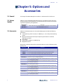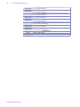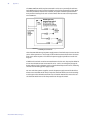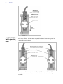
1
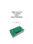
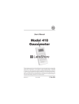
User’s Manual Model EM4-HVA Electromagnet Model EM4-HVA H-yoke, variable gap, horizontal field, 100 mm (4 inch) pole diameter electromagnet Lake Shore Cryotronics, Inc. 575 McCorkle Blvd. Westerville, Ohio 430828888 USA [email protected] [email protected] www.lakeshore.com Fax: (614) 891-1392 Telephone: (614) 891-2243 Methods and apparatus disclosed and described herein have been developed solely on company funds of Lake Shore Cryotronics, Inc. and Toyo Corporation. No government or other contractual support or relationship, excepting the collaboration with Toyo Corporation, has existed which in any way affects or mitigates proprietary rights of Lake Shore Cryotronics, Inc. in these developments. Methods and apparatus disclosed herein may be subject to U.S. Patents existing or applied for. Lake Shore Cryotronics, Inc. reserves the right to add, improve, modify, or withdraw functions, design modifications, or products at any time without notice. Lake Shore shall not be liable for errors contained herein or for incidental or consequential damages in connection with furnishing, performance, or use of this material. Rev. 1.1 P/N 119-623 12 February 2013 | www.lakeshore.com LIMITED WARRANTY STATEMENT WARRANTY PERIOD: THREE (3) YEARS 1.Lake Shore warrants that products manufactured by Lake Shore (the "Product") will be free from defects in materials and workmanship for three years from the date of Purchaser's physical receipt of the Product (the "Warranty Period"). If Lake Shore receives notice of any such defects during the Warranty Period and the defective Product is shipped freight prepaid back to Lake Shore, Lake Shore will, at its option, either repair or replace the Product (if it is so defective) without charge for parts, service labor or associated customary return shipping cost to the Purchaser. Replacement for the Product may be by either new or equivalent in performance to new. Replacement or repaired parts, or a replaced Product, will be warranted for only the unexpired portion of the original warranty or 90 days (whichever is greater).. 2.Lake Shore warrants the Product only if the Product has been sold by an authorized Lake Shore employee, sales representative, dealer or an authorized Lake Shore original equipment manufacturer (OEM). 3.The Product may contain remanufactured parts equivalent to new in performance or may have been subject to incidental use when it is originally sold to the Purchaser. 4.The Warranty Period begins on the date of Purchaser's physical receipt of the Product or later on the date of operational training and verification (OT&V) of the Product if the service is performed by Lake Shore, provided that if the Purchaser schedules or delays the Lake Shore OT&V for more than 30 days after delivery then the Warranty Period begins on the 31st day after Purchaser's physical receipt of the Product. 5.This limited warranty does not apply to defects in the Product resulting from (a) improper or inadequate installation (unless OT&V services are performed by Lake Shore), maintenance, repair or calibration, (b) fuses, software, power surges, lightning and nonrechargeable batteries, (c) software, interfacing, parts or other supplies not furnished by Lake Shore, (d) unauthorized modification or misuse, (e) operation outside of the published specifications, (f) improper site preparation or site maintenance (g) natural disasters such as flood, fire, wind, or earthquake, or (h) damage during shipment other than original shipment to you if shipped through a Lake Shore carrier. 6.This limited warranty does not cover: (a) regularly scheduled or ordinary and expected recalibrations of the Product; (b) accessories to the Product (such as probe tips and cables, holders, wire, grease, varnish, feed throughs, etc.); (c) consumables used in conjunction with the Product (such as probe tips and cables, probe holders, sample tails, rods and holders, ceramic putty for mounting samples, Hall sample cards, Hall sample enclosures, etc.); or, (d) non-Lake Shore branded Products that are integrated with the Product. 7. To the extent allowed by applicable law,, this limited warranty is the only warranty applicable to the Product and replaces all other warranties or conditions, express or implied, including, but not limited to, the implied warranties or conditions of merchantability and fitness for a particular purpose. Specifically, except as provided herein, Model EM4-HVA Electromagnet LakeShore undertakes no responsibility that the products will be fit for any particular purpose for which you may be buying the Products. Any implied warranty is limited in duration to the warranty period. No oral or written information, or advice given by the Company, its Agents or Employees, shall create a warranty or in any way increase the scope of this limited warranty. Some countries, states or provinces do not allow limitations on an implied warranty, so the above limitation or exclusion might not apply to you. This warranty gives you specific legal rights and you might also have other rights that vary from country to country, state to state or province to province. 8.Further, with regard to the United Nations Convention for International Sale of Goods (CISC,) if CISG is found to apply in relation to this agreement, which is specifically disclaimed by Lake Shore, then this limited warranty excludes warranties that: (a) the Product is fit for the purpose for which goods of the same description would ordinarily be used, (b) the Product is fit for any particular purpose expressly or impliedly made known to Lake Shore at the time of the conclusion of the contract. (c) the Product is contained or packaged in a manner usual for such goods or in a manner adequate to preserve and protect such goods where it is shipped by someone other than a carrier hired by Lake Shore. 9. Lake Shore disclaims any warranties of technological value or of non-infringement with respect to the Product and Lake Shore shall have no duty to defend, indemnify, or hold harmless you from and against any or all damages or costs incurred by you arising from the infringement of patents or trademarks or violation or copyrights by the Product. 10.THIS WARRANTY IS NOT TRANSFERRABLE. This warranty is not transferrable. 11.Except to the extent prohibited by applicable law, neither Lake Shore nor any of its subsidiaries, affiliates or suppliers will be held liable for direct, special, incidental, consequential or other damages (including lost profit, lost data, or downtime costs) arising out of the use, inability to use or result of use of the product, whether based in warranty, contract, tort or other legal theory, regardless whether or not Lake Shore has been advised of the possibility of such damages. Purchaser's use of the Product is entirely at Purchaser's risk. Some countries, states and provinces do not allow the exclusion of liability for incidental or consequential damages, so the above limitation may not apply to you. 12.This limited warranty gives you specific legal rights, and you may also have other rights that vary within or between jurisdictions where the product is purchased and/or used. Some jurisdictions do not allow limitation in certain warranties, and so the above limitations or exclusions of some warranties stated above may not apply to you. 13.Except to the extent allowed by applicable law, the terms of this limited warranty statement do not exclude, restrict or modify the mandatory statutory rights applicable to the sale of the product to you. CERTIFICATION TRADEMARK ACKNOWLEDGMENT Lake Shore certifies that this product has been inspected and tested in accordance with its published specifications and that this product met its published specifications at the time of shipment. The accuracy and calibration of this product at the time of shipment are traceable to the United States National Institute of Standards and Technology (NIST); formerly known as the National Bureau of Standards (NBS). Many manufacturers and sellers claim designations used to distinguish their products as trademarks. Where those designations appear in this manual and Lake Shore was aware of a trademark claim, they appear with initial capital letters and the ™ or ® symbol. CalCurve™, Carbon-Glass™, Cernox™, Duo-Twist™, High-Temperature Cernox™, Gamma Probe™, SoftCal™, Quad-Lead™, Quad-Twist™, and Thermox™ are trademarks of Lake Shore Cryotronics, Inc. IDEAS™ is a trademark of Unisys Corporation and is licensed for use with Lake Shore software drivers. Copyright 1995-1999, 2001-02, 2004, 2013 Lake Shore Cryotronics, Inc. All rights reserved. No portion of this manual may be reproduced, stored in a retrieval system, or transmitted, in any form or by any means, electronic, mechanical, photocopying, recording, or otherwise, without the express written permission of Lake Shore. | www.lakeshore.com Model EM4-HVA Electromagnet i Table of Contents Chapter 1 Introduction 1.1 General . . . . . . . . . . . . . . . . . . . . . . . . . . . . . . . . . . . . . . . . . . . . . . . . . . . . . . . . . . . . . . . . . . . . . . . . . . . . . . . . 1 1.2 General Description . . . . . . . . . . . . . . . . . . . . . . . . . . . . . . . . . . . . . . . . . . . . . . . . . . . . . . . . . . . . . . . . . . 1 1.3 Specifications . . . . . . . . . . . . . . . . . . . . . . . . . . . . . . . . . . . . . . . . . . . . . . . . . . . . . . . . . . . . . . . . . . . . . . . . . 2 1.3.1 Hardware . . . . . . . . . . . . . . . . . . . . . . . . . . . . . . . . . . . . . . . . . . . . . . . . . . . . . . . . . . . . . . . . . . . . . . 2 1.3.2 Electrical . . . . . . . . . . . . . . . . . . . . . . . . . . . . . . . . . . . . . . . . . . . . . . . . . . . . . . . . . . . . . . . . . . . . . . . 2 1.3.3 Cooling . . . . . . . . . . . . . . . . . . . . . . . . . . . . . . . . . . . . . . . . . . . . . . . . . . . . . . . . . . . . . . . . . . . . . . . . . 2 1.3.4 Coil . . . . . . . . . . . . . . . . . . . . . . . . . . . . . . . . . . . . . . . . . . . . . . . . . . . . . . . . . . . . . . . . . . . . . . . . . . . . . 3 1.3.5 Polecaps . . . . . . . . . . . . . . . . . . . . . . . . . . . . . . . . . . . . . . . . . . . . . . . . . . . . . . . . . . . . . . . . . . . . . . . . 3 1.3.6 Materials . . . . . . . . . . . . . . . . . . . . . . . . . . . . . . . . . . . . . . . . . . . . . . . . . . . . . . . . . . . . . . . . . . . . . . . 3 1.3.7 General . . . . . . . . . . . . . . . . . . . . . . . . . . . . . . . . . . . . . . . . . . . . . . . . . . . . . . . . . . . . . . . . . . . . . . . . . 3 1.3.8 Shipping Dimensions . . . . . . . . . . . . . . . . . . . . . . . . . . . . . . . . . . . . . . . . . . . . . . . . . . . . . . . . . . 3 1.3.9 Power Supply . . . . . . . . . . . . . . . . . . . . . . . . . . . . . . . . . . . . . . . . . . . . . . . . . . . . . . . . . . . . . . . . . . 3 1.4 Dimensions . . . . . . . . . . . . . . . . . . . . . . . . . . . . . . . . . . . . . . . . . . . . . . . . . . . . . . . . . . . . . . . . . . . . . . . . . . . 3 1.5 Typical Field Intensity Plots . . . . . . . . . . . . . . . . . . . . . . . . . . . . . . . . . . . . . . . . . . . . . . . . . . . . . . . . . . 6 1.6 Typical Field Uniformity . . . . . . . . . . . . . . . . . . . . . . . . . . . . . . . . . . . . . . . . . . . . . . . . . . . . . . . . . . . . . . 9 1.7 Typical Remanent Field Plots . . . . . . . . . . . . . . . . . . . . . . . . . . . . . . . . . . . . . . . . . . . . . . . . . . . . . . . 10 1.8 Typical Stray Field Plots . . . . . . . . . . . . . . . . . . . . . . . . . . . . . . . . . . . . . . . . . . . . . . . . . . . . . . . . . . . . . 11 1.9 Safety . . . . . . . . . . . . . . . . . . . . . . . . . . . . . . . . . . . . . . . . . . . . . . . . . . . . . . . . . . . . . . . . . . . . . . . . . . . . . . . . 13 1.9.1 Electrostatic Discharge . . . . . . . . . . . . . . . . . . . . . . . . . . . . . . . . . . . . . . . . . . . . . . . . . . . . . . . 13 1.9.2 Identification of Electrostatic Discharge Sensitive Components . . . . . . . . . . . . 13 1.9.3 Handling Electrostatic Discharge Sensitive Components . . . . . . . . . . . . . . . . . . . 13 1.9.4 Equipment Safety Symbols . . . . . . . . . . . . . . . . . . . . . . . . . . . . . . . . . . . . . . . . . . . . . . . . . . . 14 Chapter 2 Installation 2.1 2.2 2.3 2.4 2.5 2.6 2.7 General . . . . . . . . . . . . . . . . . . . . . . . . . . . . . . . . . . . . . . . . . . . . . . . . . . . . . . . . . . . . . . . . . . . . . . . . . . . . . . . 15 Site Planning . . . . . . . . . . . . . . . . . . . . . . . . . . . . . . . . . . . . . . . . . . . . . . . . . . . . . . . . . . . . . . . . . . . . . . . . . 15 Cooling Water Requirements . . . . . . . . . . . . . . . . . . . . . . . . . . . . . . . . . . . . . . . . . . . . . . . . . . . . . . . 15 Unpacking . . . . . . . . . . . . . . . . . . . . . . . . . . . . . . . . . . . . . . . . . . . . . . . . . . . . . . . . . . . . . . . . . . . . . . . . . . . 15 Accessories . . . . . . . . . . . . . . . . . . . . . . . . . . . . . . . . . . . . . . . . . . . . . . . . . . . . . . . . . . . . . . . . . . . . . . . . . . . 16 Installation Procedure . . . . . . . . . . . . . . . . . . . . . . . . . . . . . . . . . . . . . . . . . . . . . . . . . . . . . . . . . . . . . . . 16 Return and Shipping Procedure . . . . . . . . . . . . . . . . . . . . . . . . . . . . . . . . . . . . . . . . . . . . . . . . . . . . . 19 Chapter 3 Operation 3.1 3.2 3.3 3.4 3.5 General . . . . . . . . . . . . . . . . . . . . . . . . . . . . . . . . . . . . . . . . . . . . . . . . . . . . . . . . . . . . . . . . . . . . . . . . . . . . . . . 21 General Check . . . . . . . . . . . . . . . . . . . . . . . . . . . . . . . . . . . . . . . . . . . . . . . . . . . . . . . . . . . . . . . . . . . . . . . 21 Operation . . . . . . . . . . . . . . . . . . . . . . . . . . . . . . . . . . . . . . . . . . . . . . . . . . . . . . . . . . . . . . . . . . . . . . . . . . . . 21 Adjusting the Magnet Air Gap . . . . . . . . . . . . . . . . . . . . . . . . . . . . . . . . . . . . . . . . . . . . . . . . . . . . . . . 21 Pole Cap Replacement . . . . . . . . . . . . . . . . . . . . . . . . . . . . . . . . . . . . . . . . . . . . . . . . . . . . . . . . . . . . . . 21 Chapter 4 Maintenance 4.1 4.2 4.3 4.4 4.5 4.6 General . . . . . . . . . . . . . . . . . . . . . . . . . . . . . . . . . . . . . . . . . . . . . . . . . . . . . . . . . . . . . . . . . . . . . . . . . . . . . . . 25 Adjusting the Pole-Locking Lever Motion . . . . . . . . . . . . . . . . . . . . . . . . . . . . . . . . . . . . . . . . . . . 25 Rust Prevention . . . . . . . . . . . . . . . . . . . . . . . . . . . . . . . . . . . . . . . . . . . . . . . . . . . . . . . . . . . . . . . . . . . . . . 25 Rust Removal . . . . . . . . . . . . . . . . . . . . . . . . . . . . . . . . . . . . . . . . . . . . . . . . . . . . . . . . . . . . . . . . . . . . . . . . 25 Foreign Matter . . . . . . . . . . . . . . . . . . . . . . . . . . . . . . . . . . . . . . . . . . . . . . . . . . . . . . . . . . . . . . . . . . . . . . . 25 Storage . . . . . . . . . . . . . . . . . . . . . . . . . . . . . . . . . . . . . . . . . . . . . . . . . . . . . . . . . . . . . . . . . . . . . . . . . . . . . . . 26 Chapter 5 Options and Accessories 5.1 General . . . . . . . . . . . . . . . . . . . . . . . . . . . . . . . . . . . . . . . . . . . . . . . . . . . . . . . . . . . . . . . . . . . . . . . . . . . . . . . 27 5.2 System Options . . . . . . . . . . . . . . . . . . . . . . . . . . . . . . . . . . . . . . . . . . . . . . . . . . . . . . . . . . . . . . . . . . . . . . 27 5.3 Accessories . . . . . . . . . . . . . . . . . . . . . . . . . . . . . . . . . . . . . . . . . . . . . . . . . . . . . . . . . . . . . . . . . . . . . . . . . . . 27 | www.lakeshore.com Appendix A Flow Switch Installation A.2 A.3 A.4 A.5 A.6 A.7 Appendix B Units for Magnetic Properties B.1 Units for Magnetic Properties . . . . . . . . . . . . . . . . . . . . . . . . . . . . . . . . . . . . . . . . . . . . . . . . . . . . . . . 35 Model EM4-HVA Electromagnet General . . . . . . . . . . . . . . . . . . . . . . . . . . . . . . . . . . . . . . . . . . . . . . . . . . . . . . . . . . . . . . . . . . . . . . . . . . . . . . 29 EM4-HVA Replacement Flow Switch . . . . . . . . . . . . . . . . . . . . . . . . . . . . . . . . . . . . . . . . . . . . . . . 29 EM4-HVA Flow Switch Specifications . . . . . . . . . . . . . . . . . . . . . . . . . . . . . . . . . . . . . . . . . . . . . . . 29 EM4-HVA Flow Switch Installation . . . . . . . . . . . . . . . . . . . . . . . . . . . . . . . . . . . . . . . . . . . . . . . . . 29 EM4-HVA Flow Switch Adjustment . . . . . . . . . . . . . . . . . . . . . . . . . . . . . . . . . . . . . . . . . . . . . . . . . 31 EM4-HVA Flow Switch Operating Mode . . . . . . . . . . . . . . . . . . . . . . . . . . . . . . . . . . . . . . . . . . . . 32 1.1 General 1 Chapter 1: Introduction 1.1 General The EM4-HVA electromagnet is suited for many applications such as susceptibility measurements, Hall effect studies, magneto-optical studies, and magnetic resonance demonstrations. We welcome comments concerning this manual. Although we try to keep it error-free, some may occur. When reporting a problem, describe it briefly and include the manual title and page number. Send your comments to Lake Shore Cryotronics, Inc., Attn: Technical Publications, 575 McCorkle Blvd., Westerville, Ohio 43082-8888. 1.2 General Description Continuously adjustable air gap allowing rapid air gap changes to suit individual experiments assures magnet versatility. Poles lock in place by turning engaging levers on each side of the electromagnet frame. D D D D D D D D EM4 models achieve unmatched field intensities in air gap widths up to 11 cm (4.3 inches) with cylindrical or tapered pole caps. Water-cooled coils provide excellent field stability and uniformity when high power is required to achieve the maximum field capability for the electromagnet. Easy pole cap exchange by 3-bolt pole caps, for variations in pole face diameters. Accurate pole alignment by precise construction of air gap adjustment mechanism. Precision yokes of magnetically soft, high purity steel assure precise pole face alignment critical for good homogeneity and reproducibility. The H-Yoke frame design is reclined at a 40° angle for enhanced air gap accessibility. The compact size of the Model EM4-HVA permits convenient bench-top mounting. Couple the Model EM4-HVA with a Lake Shore 643 magnet power supply (MPS) to form a versatile laboratory electromagnet characterization system. The advanced design of the true bipolar Model 643 MPS allows for very rapid, uniform magnetic field reversal resulting in enhanced Hall effect measurement of semiconductors and other materials, and improved four quadrant hysteresis loops with shortened integration intervals. The Model 643 MPS also provides rapid, uniform magnetic field reversal to avoid discontinuities that often occur during zero cross-over when using non bipolar power supplies. The basic components of the Model EM4-HVA electromagnet are shown in the picture below. The magnet base supports the magnet frame. The electromagnet poles are composed of iron, providing a high permeability core for the electromagnet generating coils. The generating coils, when energized with DC current, provide the turns × current, or NI, which magnetizes the high permeability core iron creating a high magnetic flux density in the airgap of the electromagnet. The magnet frame provides a magnetic return path for the generated flux. The entire structure becomes a low loss, high efficiency magnetic circuit optimized for magnetic field uniformity and intensity. The two continuously adjustable pole adjusters allow for easy modification of the magnet airgap, located between the pole caps of the electromagnet. The pole lock allows the user to lock the electromagnet poles in place, after an airgap adjustment is made. A variety of pole cap diameters are offered allowing the user to choose the appropriate combination of field intensity and uniformity for the required application. Pole caps are also available as special optical access models, which allow for axial optical access to the electromagnet airgap for lasers or other optical devices. | www.lakeshore.com 2 cHAPTER 1: Introduction FIGURE 1-1 Model EM4-HVA electromagnet, front view 1.3 Specifications The following sections provide the specifications for the Model EM4-HVA. 1.3.1 Hardware Type: Electromagnet, resistive coils, iron core and yoke Pole diameter, nominal: 100 mm (4 in) Air gap: 0 to 11.0 cm (4.3 in.) continuously variable Coil configuration: 2 coils wired in series Frame design: H-Frame, with left and right pole adjusters and locks Field +B vector: Horizontal, left to right, from front view Frame, angle of recline: 40 degrees Optical access compatibility: Optical model only 1.3.2 Electrical Maximum current: ±70 A Nominal voltage: ±35 volts (approx ±38 volts at max. coil temperature) Nominal power: 2.5 kVA (2.65 kVA at max temperature) Duty cycle: 100% Connections, power: Copper terminal lug with mounting hole for up to 8mm or 5/16 in fasteners Typical coil resistance: Each Coil 2 Coils in Series Nominal 0.25 Ω 0.5 Ω Resistance, cold, typical 0.23 Ω 0.46 Ω Resistance, max., typical 0.27Ω 0.54 Ω TABLE 1-1 Typical coil resistance 1.3.3 Cooling Model EM4-HVA Electromagnet Coolant: Clean, filtered municipal tap water or water in closed recirculating system Water flow rate: 7.6 L (2.0 gal) per minute) Water pressure drop: 200 kPa (30 PSI) Max supply pressure: 700 kPa (100 PSI) 1.3.4 Coil 3 Water recirculating chiller cooling capacity: 2.5 kW (8530 BTU/Hr) Water inlet temperature: 15 to 25 °C (59 to 77 °F) Water flow switch, activation flow, approximate: Switch closure at 7.6 L (2.0 gal) per minute, normally open Water flow switch, deadband, approximate: 0.8 L (0.2 gal) per minute Water flow switch, contact rating: 2 A, 250 VAC, 60 VA, reed contact Over-temperature limit switch, activation temperature, approximate: Switch opens at 45 °C (113 °F), normally closed, auto-resetting Connections, cooling, after “T” fittings and flow switch: 1cm (3/8in) hose barb Connections, cooling, bare coil: 0.635 cm ( 1/4 in) NPT to 1cm (3/8 in) hose barb adaptors 1.3.4 Coil Inter-coil spacing: 12.0 cm (4.75 in.) Coil width:12.0 cm (4.75 in.) Coil diameter: 31.1 cm (12.25 in.) Connection, over-temperature limit switch: 2 male quick connect terminals 1.3.5 Polecaps Available polecap sizes, nominal diameter: 25 mm (1 in), 50 mm (2 in), 75 mm (3 in) 100 mm (4 in) Taper angle for focusing: 45 degrees Corrosion protection: Electroless Nickel Fasteners, 3 per polecap: 1/4-20 Alloy steel socket head cap screws (1/4 in dia, 20 threads per in) 1.3.6 Materials Yoke: Low carbon steel Pole/Core: Low carbon steel Pole caps: Low carbon steel Coil conductor: Copper Coil cooling: Copper 1.3.7 General Size, magnet only (height, width, depth): 38.7 cm (15.25 in) × 84.5 cm (33.25 in) × 50.8 cm (20 in.) Weight, magnet only: 227 kg (500 lbs) Weight, standard base only: 63 kg (138 lbs) Floor loading: Check weight against structural capacity of floor 1.3.8 Shipping Dimensions Shipping dimensions (height, width, depth): 130 cm (51 in) × 122 cm (48 in) × 97 cm (38 in.) Shipping weight: 420 kg (925 lbs) 1.3.9 Power Supply Suggested magnet power supply: Lake Shore Model 643 (nominal 70 A, 35 V, 2.5 kW) 1.4 Dimensions The following figures show dimensions of the Model EM4-HVA from the front, side and rear views . | www.lakeshore.com 4 cHAPTER 1: Introduction FIGURE 1-2 Model EM4-HVA electromagnet dimensions, front view Model EM4-HVA Electromagnet 1.4 Dimensions 5 FIGURE 1-3 Model EM4-HVA electromagnet dimensions, side view | www.lakeshore.com 6 cHAPTER 1: Introduction 10.7 cm (4.2 in) – DC POWER + DC POWER 2 × 8 mm [5/16 in] diameter holes on terminal lugs 11.4 cm (4.5 in) WATER OUT THERMAL INTERLOCK WATER IN 2 × male tab disconnect terminals 2 × 1/4 in FNPT with 1/4 in MNPT to 10 mm (3/8 in) hose barb adapter FIGURE 1-4 EM-4 coil connection block, rear view Depending on the design of the generating coils provided with your electromagnet, there may be a copper grounding lug provided on the coil connection block at the rear of each electromagnet coil. See Chapter 2, Section 2.6, “Installation Procedures” for more information on electromagnet grounding. 1.5 Typical Field Intensity Plots The maximum field plots depicted in this manual are typical response curves measured on production units. Response is typical and subject to some variation. However, the response in your EM4-HVA should not vary significantly from the data illustrated below. The Model EM4-HVA max field versus air gap versus pole cap diameter is one of the most useful plots for determining available field levels for a particular airgap length and polecap diameter combination. This plot shows the maximum field available at a particular airgap with 70 A of applied current for all four main polecap combinations: 100, 75, 50 and 25 mm (4,3,2 and 1 in). Use this curve, along with data from the field uniformity section of this manual, to determine which pole caps are appropriate for a particular application. Model EM4-HVA Electromagnet 1.5 Typical Field Intensity Plots 7 35 30 25 100 mm (4 in) 75 mm (3 in) 50 mm (2 in) 25 mm (1 in) Field (kG) 20 15 10 5 0 0 20 40 60 Magnet Air Gap (mm) 80 100 120 FIGURE 1-5 Model EM4-HVA maximum field versus air gap at 4 polecap diameters; EM4-HVA at 70 A 35 30 5 mm 10 mm 1 5mm 16.3 mm 20 mm 22.9 mm 25 mm 28.4 mm 38.1 mm 50 mm 50.8 mm 75 mm 100 mm 110 mm Field (kG) 25 20 15 10 5 0 0 10 20 30 40 Current (A) 50 60 70 FIGURE 1-6 Field versus current versus airgap: EM4-HVA 25 mm (1 in) Fe polecaps | www.lakeshore.com cHAPTER 1: Introduction 8 30 25 Field (kG) 20 15 10 5 0 0 10 20 30 40 Current (A) 50 60 70 5 mm 10 mm 15 mm 16.3 mm 20 mm 22.9 mm 25 mm 28.4 mm 38.1 mm 50 mm 50.8 mm 75 mm 100 mm 110 mm FIGURE 1-7 Field versus current versus airgap: EM4-HVA 50 mm (2 in) Fe polecaps 25 20 5 mm 10 mm 15 mm 16.3 mm 20 mm 22.9 mm 25 mm 28.4 mm 38.1 mm 50 mm 50.8 mm 75 mm 100 mm 110 mm Field (kG) 15 10 5 0 0 10 20 30 40 Current (A) 50 60 FIGURE 1-8 Field versus current versus airgap: EM4-HVA 75 mm (3 in) Fe polecaps Model EM4-HVA Electromagnet 70 1.6 Typical Field Uniformity 9 25 5 mm 10 mm 15 mm 16.3 mm 20 mm 22.9 mm 25 mm 28.4 mm 38.1 mm 50 mm 50.8 mm 75 mm 100 mm 110 mm 20 Field (kG) 15 10 5 0 0 10 20 30 40 50 60 70 Current (A) FIGURE 1-9 Field versus current versus airgap: EM4-HVA 100 mm (4 in) Fe polecaps 1.6 Typical Field Uniformity The field uniformity tables depicted in this manual are typical response curves measured on production units. Response is typical and subject to some variation. The response in your EM4-HVA should not vary significantly from the data illustrated below. TABLE 1-2 lists typical field uniformity for EM4-HVA magnets. Data will be affected by the field intensity of the central magnetic field, presence of passive (ferrous materials) and active (transformers, etc.) magnetic materials and devices in the vicinity of the magnet as well as other effects. The first table gives the uniformity of field over a cubic centimeter volume centered in the magnet gap. The second table defines a cylindrical volume within which the magnetic field deviates by less than ±1% from the central field. The cylindrical volume is coaxial with the magnet poles and centered in the gap. Pole Gap Uniformity Diameter Length 1 cm3 volume cm in 10 4 7.5 3 5 2 cm in ±% 5 2 0.15 2.5 1 0.05 2.5 1 0.06 2.5 1 0.35 1.3 0.5 0.16 Percent variation in field intensity about a 1 cm cube, centered in the magnet airgap at 5000 Oe applied field TABLE 1-2 Typical EM4-HVA field uniformity: 1 cm cube | www.lakeshore.com cHAPTER 1: Introduction 10 . Pole Gap Diameter Length cm in 10 4 7.5 3 5 2 2.5 1 ±Cylindrical volume Diameter Length cm in cm in cm in 7.6 3 2.7 1.1 1.9 0.75 2.5 1 6.5 2.5 2.5 1.0 2.5 1 4.6 1.8 2.5 1.0 2.5 1 1.8 0.7 2.5 1.0 1.3 0.5 3.6 1.4 0.5 1.2 1.3 0.5 1.0 0.4 0.8 0.3 Size of cylindrical volume with less than ±1% variation in field intensity, centered in the magnet airgap at 5000 Oe applied field. TABLE 1-3 Typical EM4-HVA field uniformity: 1 cm cube 1.7 Typical Remanent Field Plots The remanent field plots depicted in this manual are typical response curves measured on production units. Response is typical and subject to some variation. However, the response in your EM4-HVA should not vary significantly from the data illustrated below. 0.7 0.6 Remanent Field B, kG 0.5 25 mm (1 in) 0.4 50 mm (2 in) 75 mm (3 in) 0.3 100 mm (4 in) 0.2 0.1 0 0 20 40 60 80 100 Magnet Air Gap, mm FIGURE 1-10 Model EM4-HVA remanent field versus air gap versus pole cap diameter Model EM4-HVA Electromagnet 120 1.8 Typical Stray Field Plots 1.8 Typical Stray Field Plots 11 The stray field plots depicted in this manual are typical response curves measured on production units. Typical response is subject to variation. As stray field may be affected by the environment near the electromagnet, it is up to the user to measure the actual stray field in your final location under real operating conditions to get an accurate depiction of the actual stray field distribution in your final location. For these measurements, The EM4-HVA was equipped with 50 mm (2 in) diameter pole caps and was set to a 50 mm (2 in) air gap. 10000 9000 8000 Field, Gauss 7000 6000 5000 4000 3000 [Gauss] 2000 1000 0 -1000 0 100 200 300 400 500 600 700 800 900 1000 Distance, mm FIGURE 1-11 Model EM4-HVA stray magnetic field versus distance (radially outward) 20 Field, Gauss 15 10 [Gauss] 5 0 0 100 200 300 400 500 600 Distance, mm FIGURE 1-12 Model EM4-HVA stray magnetic field versus distance, expanded (radially outward) | www.lakeshore.com cHAPTER 1: Introduction 12 160 140 Field, Gauss 120 100 80 60 [Gauss] 40 20 0 0 100 200 300 400 500 600 Distance, mm FIGURE 1-13 Model EM4-HVA stray magnetic field versus distance (axially outward) 20 Field, Gauss 15 10 [Gauss] 5 0 0 100 200 300 400 500 Distance, mm FIGURE 1-14 Model Em4-HVA stray magnetic field versus distance, expanded (axially outward) Model EM4-HVA Electromagnet 600 1.9 Safety 13 1.9 Safety Equipment protected throughout by double insulation or reinforces insulation (equivalent to Class II of IEC 536—see Annex H) Direct current (power line) Alternating current (power line) Alternating or direct current (power line) 3 CAUTION: High voltages; danger of electric shock Three-phase alternating current (power line) Earth (ground) terminal ! Protective conductor terminal CAUTION or WARNING: See included documentation CAUTION: Hot surface Frame or chassis terminal On (supply) Off (supply) FIGURE 1-15 Safety symbols | www.lakeshore.com 14 cHAPTER 1: Introduction Model EM4-HVA Electromagnet 2.1 General 15 Chapter 2: Installation 2.1 General This chapter covers electromagnet installation: Site planning in section 2.2, cooling water requirements in section 2.3, unpacking in section 2.4, accessories in section 2.5, installation procedure in section 2.6, and the return and shipping procedure in section 2.7. 2.2 Site Planning Consider these things when choosing the installation site: D Magnetic environment: minimize environmental magnetic fields. Common sources of interference are fluctuating loads on adjacent power lines, heavy-duty power transformers, elevator motors and similar electromagnetic devices. D Structural support/floor strength: allow for adequate support of components and handling equipment. The floor must be sufficiently rigid for minimum vibration from adjacent dynamic loads as well as sufficiently strong to hold the large mass of the electromagnet itself. D Service utilities: maintain room temperature and cooling water specifications. D Ambient temperature: magnet cooling water system operates at designed thermal efficiency when room temperature is within normal bounds. D Equipment handling: ensure adequate moving equipment, transportation route clearances, and supervision by qualified personnel. D Ventilation: ensure adequate ventilation, especially during use of cryogens. D Other factors: existing or planned facilities; local safety, electrical, and building codes; access to all sides of the equipment for operating and servicing. 2.3 Cooling Water Requirements The EM4-HVA electromagnet requires 7.6 liters (2 gallons) per minute of water flow at a pressure drop of 200 kPa (30 PSI). The rated pressure drop includes the restrictions from “T” fittings and 1 cm (3/8 in) I.D. water distribution lines to the coils as well as restrictions from the factory flow switch. Please accommodate any additional pressure drop due to local supply and drain lines. Standard municipal water systems are generally suitable to cool the magnet, provided proper flow is maintained. Use a water filter, flowmeter, and pressure gauges to monitor coolant water flow. If the water temperature is well above +25 °C (77 °F), install a watercooling device at the magnet water inlet. Algaecide may be used to limit growth of biological contaminates in the cooling water. To avoid moisture condensation on the magnet, adjust the cooling system to keep the magnet coils above condensation temperature. Pure distilled water is not compatible with the copper cooling lines used in the electromagnet. 2.4 Unpacking Inspect shipping container for damage. If it is damaged or the inside cushioning material appears stressed, check the shipment for completeness and proper operation (following procedures outlined in this manual). Keep all packing material in case of return. If components are missing from your shipment, or if there is mechanical damage or defect (apparent or concealed), notify Lake Shore. If the shipping container or cushioning material shows signs of stress, notify the carrier as well as Lake Shore. Keep the shipping materials for inspection by the carrier. | www.lakeshore.com 16 CHAPTER 2: Installation 2.5 Accessories The standard Model EM4-HVA electromagnet includes the following accessories: Quantity Description 2 Power Cables (Attached) 1 Flow Switch Kit (Refer to Appendix A) 1 Allen Wrench Set TABLE 2-1 EM4-HVA accessories Refer to Chapter 5 for a complete list of electromagnet accessories. 2.6 Installation Procedure Follow these procedures to install the magnet. The coils are not rigidly attached to the magnet yoke. When moving the magnet, damage may occur if the coils as not secured. During shipment, dense packing foam or wedges placed between the coils holds them firmly in place. Do not remove this material until the magnet is installed in the final location. 1. Leave the magnet bolted to the shipping pallet during transportation to the installation site; it protects the magnet from vibration and the effects of an uneven floor. Do not subject the magnet to sudden bumps or jolts. To avoid danger to personnel and equipment damage, bolt the magnet to the stand, and bolt the stand to the floor. If you are not using the stand, bolt the magnet directly to floor. 2. Remove the shipping pallet and use the appropriate lifting equipment to position the magnet (and stand, if present) at the planned location. 3. Mark the bolt holes, move the magnet, and drill the bolt holes. 4. Insert the bolt studs in the holes and secure. 5. Replace the magnet (and stand) over the studs and bolt in place. 6. Check the pole caps for signs of minor rust or corrosion. Due to changes in humidity and temperature during transportation, it is possible for the pole, pole cap and other steel surfaces to become wet causing minor corrosion to form. This is a minor surface effect, which can be removed with a 4/0 grit or finer crocus cloth. 7. Connect the water supply to the 1 cm (3/8 in ) hose barb fittings on the magnet rear (see section A.2 for flow switch installation). Each electromagnet coil has one inlet (Lower) and one outlet (Upper) water fitting. The lines to each individual coil are paralleled at the factory with reinforced 1cm (3/8 in) I.D. hoses and 2 “T” fittings. This produces a single inlet line—a 1 cm (3/8 in) hose barb “T” fitting and one outlet line—another 1cm (3/8 in) hose barb “T” fitting. A hose and flowswitch are connected to the outlet. Finally, another 1cm (3/8 in) barb fitting at the flowswitch becomes the final outlet. 8. Using radiator clamps or other securing devices, attach a 1 cm (3/8 in.) I.D. drain hose to this outlet line. 9. Using radiator clamps or other securing devices attach a 1 cm (3/8 in.) I.D. supply hose to the inlet line. 10. Test for leaks before attaching power cables. Model EM4-HVA Electromagnet 2.6 Installation Procedure Coil out Coil out 1/4 inch FNPT 1/4 inch MNPT to 1 cm (3/8 inch) hose barb to interlock circuit 17 flow switch cable T-fitting 2 places 1 cm (3/8 inch) hose barb to 1/2 inch MNPT adaptor to coil thermal interlocks Coil in Coil in 1/4 inch FNPT 1/4 inch MNPT to 1 cm (3/8 inch) hose barb Ear clamps (6 places) In flow switch 1/2 inch FNPT inlet/outlet 21.5 cm (8.5 inch) hose section (5 places) 1/2 inch MNPT to 1 cm (3/8 inch) hose barb Out FIGURE 2-1 Magnet flow switch, hose and fittings for installation 11. When purchased with a Lake Shore system or Lake Shore power supply, the coil thermal interlocks and the flow switch interlock will be pre-wired into the normally closed safety interlock of the included power supply which runs the electromagnet. For the Model 643 power supply, make certain the 4 pin screw terminal connector is mated to the remote enable terminals at the rear of the Model 643 power supply. See Section A4.1, EM4-HVA Flow Switch Installation for details.. 12. From the factory, the flow switch and the coil thermal interlocks are wired in series. The factory flow switch is set for contact closure when adequate water flow is detected. When not supplied as part of a Lake Shore System, connect the flow switch to a normally closed interlock to ensure the electromagnet is protected from inadequate flow. 13. One normally closed thermal switch is attached to each electromagnet coil. The thermal switches have standard male disconnect terminal style leads. Connect to the thermal switches with female disconnect terminals. 14. The normally closed thermal switch will open when the coil reaches +45 C. When the electromagnet coil cools, the thermal switch will reset and return to a closed condition. When not supplied as part of a Lake Shore System, connect in series with normally closed interlock circuitry so that any open in the system will result in a system shutoff. The normally closed thermal switches on each coil wired in series with a normally closed flow switch will provide protection to the electromagnet for many common cooling-related fault conditions. | www.lakeshore.com 18 CHAPTER 2: Installation FIGURE 2-2 Electromagnet connections 15. A ground connection (tapped hole) is available at the rear of the electromagnet frame. This ground point is provided for customers who would like to use the electromagnet frame as a signal ground or will be bringing hazardous live voltages near the electromagnet and would like to make it an electrical safety ground. Please verify suitability for such a function and compatibility with local and national electrical codes before making ground connections. Scrape off excess paint near the connecting screw to ensure a good electrical contact with the bare steel of the electromagnet frame. Do not connect or disconnect the electromagnet to or from the magnet power supply without first reducing output current to zero amperes and turning off the supply. 16. Connect D.C. power cables from a magnet power supply to the electromagnet. a. The power supply connections are located on the rear of the coils (if the cables are already connected, check screw tightness). To access the electrical connection, remove the rubber insulated boots. b. Connect the power supply cables to the terminal blocks on the rear of the coils. The Electromagnet is wired for a nominal 0.5 Ohm Series load. In addition to the Positive and Negative terminals, one jumper wire is required for the Series connection between the two coils, as shown in figure 2-2. c. Replace rubber insulated boots before operating magnet. d. Note terminal polarity. The Negative terminal is on the Left and the Positive terminal is on the Right, as you look at the coil connection block from the rear of the electromagnet. Typical coil wiring is shown in FIGURE 2-2. Water inlet and outlet are also shown. The direction of the B field is from Left to Right, when facing the magnet from the front. The wiring in FIGURE 2-2 assumes coils wound in a certain direction. If you wire the magnet and get a zero field at the center, the coils are wound backwards. You must reverse both of the leads on one coil. The magnet coils in FIGURE 2-2 are shown connected in series (0.5 ). Model EM4-HVA Electromagnet 2.7 Return and Shipping Procedure 19 17. Turn on the cooling water and adjust the flow rate: D D Model EM4-HVA: 7.6 liters per minute (2 gallons per minute) Model EM7-HVA: 18. Readjust the fittings if any leaking is observed. 2.7 Return and Shipping Procedure If the electromagnet appears to operate incorrectly, contact Lake Shore or a factory representative for a Returned Material Authorization (RMA) Number. Returns will not be accepted without an RMA number. Attach a tag with the following information when returning: D D D D RMA Number. Model and Serial Number. User's Name, Company, Address, Phone Number, and Fax Number. Malfunction Symptoms. Any water left in the cooling lines may freeze during shipping and cause irreversible damage to the magnet coils. Pack the magnet in the original shipping crate (if possible). Fasten it upright to a pallet large enough and rated to handle the magnet weight. Use compressed air to force water out of the cooling lines in the coils. The coils freely rest on the poles. To prevent damage, fix coils in place during shipment. The magnet will be damaged if turned on it's side. Wedge padded wood blocks or high density foam between the coils to hold them against the magnet frame. Protect the magnet by wrapping in heavy paper or plastic. Seal with plastic tape. Make a wood box large enough to cover the whole magnet without touching it and fasten it to the pallet. Affix shipping labels, FRAGILE warnings, UPRIGHT labels, and weight of the shipment on the outside of the crate. Also write the RMA number on the outside of the shipping crate and on packing slip. Use a shipping company that can handle the weight. | www.lakeshore.com 20 CHAPTER 2: Installation Model EM4-HVA Electromagnet 3.1 General 21 Chapter 3: Operation 3.1 General Read the entire manual and check all instruments for proper operation prior to operating the system. This chapter covers a general check in section 3.2, operation in section 3.3, magnet air gap in section 3.4, and pole cap replacement in section 3.5. 3.2 General Check Before operating the magnet, verify proper electrical connections, cooling water flow, inlet pressure, and temperature. 3.3 Operation The magnet power supply provides current to the magnet. There are no operating controls on the magnet. Rotating hand knobs on the side of the magnet allows users to vary the air gap from 0 to 11.0 cm (0 to 4.3 in). Always set current to zero amps and turn off power supply before adjusting the magnet. After adjusting pole spacing, lock poles in place by securing the locking levers on the EM4HVA. 3.4 Adjusting the Magnet Air Gap The electromagnet air gap or pole gap is the distance between the left and right polecap, at the center of the electromagnet. The EM4-HVA has a continuously adjustable air gap. For a given set of pole caps, increasing the magnet’s air gap decreases magnetic field intensity while decreasing the magnet's air gap increases magnetic field intensity. To change the air gap, follow these procedures . 1. Unlock the poles. To unlock the movable poles, turn the pole-locking levers (located on the front face of the main body of the electromagnet) counter-clockwise, until they rotate freely. This unscrews the pole-locking screw, releasing the clamping force which 'locks' the poles. 2. Move pole adjusters. The pole adjusters are located at the ends of the electromagnet. Each one has adjusting handles which appear as spokes. When the poles are unlocked, the spokes may be rotated to change the air gap position and distance. 3. Eliminate pole adjuster backlash. When making the final adjustment of an air gap, it is preferable to rotate the pole adjuster at least one turn outward to eliminate the backlash in the pole adjuster's screw mechanism. Eliminating the screw backlash in this manner will minimize unwanted pole deflection when large pull forces develop between the poles. The pull force develops whenever large fields are present in the electromagnet airgap. 4. Lock poles. To lock the poles, turn the pole-locking levers clockwise, until you feel significant resistance, which indicates the poles are locked. 3.5 Pole Cap Replacement The Model EM4-HVA electromagnet utilizes replaceable pole caps. If another geometry of pole cap is desired, the existing pole caps can be unbolted and another pair can be installed. Most pole caps are of either a straight or a tapered design, focusing the magnetic flux from the 100 mm (4 in) pole core to the diameter of the installed pole cap’s face. Generally, pole caps with a larger pole face diameter will give | www.lakeshore.com 22 CHAPTER 3: Operation higher field uniformity and lower magnetic field density, while pole caps focused to a smaller pole face will yield higher fields and lower field uniformity. Standard pole caps are made of high purity iron with a thin electroless nickel finish for corrosion resistance. Pole caps comprised of materials with higher saturation induction, such as FeCo, can also be installed to further increase field strength. To remove a pole cap, you must unbolt the three pole cap retaining screws, remove the old pole caps, and attach the new pole caps using three socket head cap screws of appropriate length. A hex key kit is provided to assist in fastening the socket head cap screws. Due to changes in the mounting geometry of the pole caps, screw lengths vary with pole cap geometry. See the table below for the correct screw length when attaching standard Lake Shore 45 degree taper angle pole caps. You may wish to Degauss the pole caps before removing them from the pole caps. Residual magnetism may hold the pole caps in contact with the pole caps with enough force to make it difficult to separate them. You can reduce residual magnetism to a minimum by alternately reversing the magnetic field polarity and gradually reducing the energizing current to near zero. The pole caps are then easily removed from the pole caps using a wrench. Use a light oil on the threads of the pole core. Handle the pole caps with care. Deep dents or scratches on pole caps can impair the magnetic field homogeneity. When installing the pole caps, place a piece of soft material (cardboard, towel, etc.) beneath them to prevent accidental damage if they fall during installation. Follow this procedure to replace a pole cap. 1. Set power supply current output to zero. 2. Turn the power supply off. 3. Make certain you have the correct length of screws for the pole cap geometry you will be using. The pole caps you want to install may have a different length than the ones on the electromagnet now. See the table below to make certain you have the correct mounting screws. Nominal pole cap face diameter 1/4–20 screw length 100 mm 4 in 57 mm 2.25 in 75 mm 3 in 45 mm 1.75 in 50 mm 2 in 32 mm 1.25 in 25mm 1 in 19 mm 0.75 in TABLE 3-1 EM4-HVA polecap and screw length 4. Unlock the pole-locking levers so the pole caps move in and out freely. 5. Rotate one pole adjuster’s spokes to move one pole cap outward until the front of the pole cap is as far out as it can be moved. 6. Rotate the opposite pole adjuster's spokes to move the other pole cap inward until the pole cap is outside of the coil surface. The pole cap is now ready to be removed. 7. Using the hex wrench provided, unscrew the mounting bolts one turn counterclockwise. Continue carefully unscrewing the pole cap mounting bolts until the pole cap is free. It is important to hold onto the pole cap when unscrewing the mounting bolts. The pole cap may be damaged if it suddenly disengages from the pole piece and drops against a hard surface. Standard right-hand threads are used in the pole cap to pole core mounting. When installing pole caps, keep the threads and surface free of any foreign material. A thin film of grease on all the surfaces prevents rust. 8. Align the new pole cap with the pole core threaded holes. Model EM4-HVA Electromagnet 3.5 Pole Cap Replacement 23 9. Using the mounting bolts, attach the new pole cap to the pole core. Before final tightening, turn the pole adjuster to move the pole cap outward by five turns. This will draw the polecap into the pole sleeve and perform a final alignment of pole cap, pole core and sleeve. 10. Use the hex wrench to finally tighten the cap against the pole piece. 11. Rotate the pole adjuster spokes to move the new pole cap’s pole outward until the front of the pole cap is as far outward as it can be moved. 12. Repeat Steps 4 thru 11 to change the other pole cap. 13. Rotate the pole adjuster spokes to move the poles to set the air gap. As the final adjustment of airgap, it is preferable to rotate the pole adjuster at least one turn outward to eliminate the backlash in the pole adjuster’s screw mechanism. Eliminating the screw backlash will minimize unwanted pole deflection when large pull forces develop due to the large fields in the electromagnet airgap. 14. Lock pole caps in place | www.lakeshore.com 24 CHAPTER 3: Operation Model EM4-HVA Electromagnet 4.1 General 25 Chapter 4: Maintenance 4.1 General This chapter describes the general maintenance to be performed on the Model EM4-HVA. 4.2 Adjusting the Pole-Locking Lever Motion The pole-locking lever has a ratcheting mechanism which may be used to adjust the movement of the pole locking levers. To change their movement, follow this procedure. 1. Pull up on the central portion of the pole-locking lever. This frees the pole-locking lever from the pole-locking screw. 2. Rotate the pole-locking lever (it should move independently of the screw) to the desired position. You may need to hold the central screw with a hex key to ensure it moves independently. 3. Release the pole locking lever to re-engage the screw. Generally, it is desirable that the pole-locking lever be able to lock and unlock the pole caps in one motion, without having to re-adjust the ratcheting mechanism. 4.3 Rust Prevention Follow these tips to prevent rust on your electromagnet. D D D D Wipe clean all pole and polecap surfaces with a clean, lint-free cloth lightly oiled with high quality light oil. Maintaining a layer of light oil will prevent rust buildup on the steel parts of the electromagnet. Even corrosion-resistant parts are subject to deterioration. To oil the pole and sleeve, retract the left pole fully into the electromagnet coil, extend the right pole fully, and lubricate the extended pole. Repeat for the opposite pole. Running the pole adjuster’s screw mechanism from end to end is also good for the electromagnet. Verify the motion is smooth and does not jam at any point in the travel. If problems are encountered when moving the mechanism, the lead screw and/or sleeve may need to be cleaned and lubricated. Consult with the factory. When exchanging pole caps, be certain to use light oil on the exposed pole core mating surface to keep it rust-free. Keeping these parts oiled and free from contamination is a good preventative measure. If condensation is seen on the exterior of the electromagnet, wipe it away with a soft clean dry cloth to prevent corrosion. 4.4 Rust Removal Remove all traces of rust with crocus cloth 4/0 grit or finer. Remove all traces of abrasive with a soft clean cloth. 4.5 Foreign Matter Remove all traces of foreign matter from pole caps with a soft clean cloth. Do not let foreign material fall into the sleeve of the electromagnet. Due to tight pole-to-sleeve tolerances, any foreign matter introduced into the sleeve when the poles are retracted may cause future operating problems. | www.lakeshore.com 26 CHAPTER 4: Maintenance 4.6 Storage Model EM4-HVA Electromagnet Long-term storage requires some precautions to be taken to prevent deterioration of the electromagnet and it's componentry. High or low temperatures can cause soft and hard coolant lines to burst and/or fail. Freezing temperatures can cause water to freeze and burst—even the hard lines. Drain any coolant from the cooling lines. Additionally, use air pressure to force out any remaining water from the internal coil cooling lines. Follow Rust prevention measures mentioned above. A package of desiccant may be stored with the magnet to reduce effects from a moist storage environment. 5.1 General 27 Chapter 5: Options and Accessories 5.1 General This chapter lists EM4-HVA options in section 5.2 and accessories in section 5.3. 5.2 System Options TABLE 5-1 lists available EM4-HVA Electromagnets. The electromagnets can be tailored to fit many custom applications. Consult the factory for assistance in configuring electromagnets for your application. Model number Description EM4-HVA-S H-yoke, variable gap (set by rotating hand spokes), 4-inch diameter pole caps, with stand. EM4-HVA-O-S Same as EM4-HVA with optical access TABLE 5-1 EM4-HVA series electromagnets 5.3 Accessories TABLE 5-2 lists EM4 accessories. The standard EM4 system includes the following accessories: D D D D D 1 Set of pole caps, either 25, 50, 75 or 100 mm (1, 2, 3 or 4 inch) and 6 attaching screws One pair of main lead screws for pole adjuster, optical access or standard, depending on model Flow Switch Power cables, #4 AWG, 3 m (10 feet) long Magnet base stand Accessories are devices that perform a secondary duty as an aid or refinement to the primary unit. . Model number Description Additional Standard Pole Caps (does not include bolts, order separately) EM4-1PB Pole cap, nominal 100mm (4 inch) diameter tapered to nominal 25 mm (1 inch) face EM4-2PB Pole cap, nominal 100mm (4 inch) diameter tapered to nominal 50 mm (2 inch) face EM4-3PB Pole cap, nominal 100mm (4 inch) diameter tapered to nominal 75 mm (3 inch) face EM4-4PB Pole cap, nominal 100mm (4 inch) diameter with nominal 100 mm (4 inch) face Additional Pole Caps with Optical Access Hole(s) (does not include bolts, order separately) EM4-1PB-O-1-2 Pole cap, nominal 100mm (4 inch) tapered to nominal 25 mm (1 inch) face, optical access 1 pole, 3.2mm (1/8-inch) diameter EM4-1PB-O-2-2 Pole cap, nominal 100mm (4 inch) tapered to nominal 25 mm (1 inch) face, optical access both poles, 3.2mm (1/8-inch) diameter EM4-1PB-O-1-4 Pole cap, nominal 100 mm (4 inch) tapered to nominal 25 mm (1 inch) face, optical access 1 pole, 6.4mm (1/4-inch) diameter EM4-1PB-O-2-4 Pole cap, nominal 100 mm (4 inch) tapered to nominal 25 mm (1 inch) face, optical access both poles, 6.4mm (1/4-inch) diameter EM4-2PB-O-1-2 Pole cap, nominal 100 mm (4 inch) tapered to nominal 50 mm (2 inch) face, optical access 1 pole, 3.2mm (1/8-inch) diameter EM4-2PB-O-2-2 Pole cap, nominal 100 mm (4 inch) tapered to nominal 50 mm (2 inch) face, optical access both poles, 3.2mm (1/8-inch) diameter EM4-2PB-O-1-4 Pole cap, nominal 100 mm (4 inch) tapered to nominal 50 mm (2 inch) face, optical access 1 pole, 6.4mm (1/4-inch) diameter EM4-2PB-O-2-4 Pole cap, nominal 100 mm (4 inch) tapered to nominal 50 mm (2 inch) face, optical access both poles, 6.4mm (1/4-inch) diameter TABLE 5-2 EM4-HVA series electromagnets | www.lakeshore.com 28 CHAPTER 5: Options and Accessories EM4-3PB-O-1-2 Pole cap, nominal 100 mm (4 inch) tapered to nominal 75 mm (3 inch) face, optical access 1 pole, 3.2mm (1/8-inch) diameter EM4-3PB-O-2-2 Pole cap, nominal 100 mm (4 inch) tapered to nominal 75 mm (3 inch) face, optical access both poles, 3.2mm (1/8-inch) diameter EM4-3PB-O-1-4 Pole cap, nominal 100 mm (4 inch) tapered to nominal 75 mm (3 inch) face, optical access 1 pole , 6.4mm (1/4-inch) diameter EM4-3PB-O-2-4 Pole cap, nominal 100 mm (4 inch) tapered to nominal 75 mm (3 inch) face, optical access both poles, 6.4mm (1/4-inch) diameter EM4-4PB-O-1-2 Pole cap, nominal 100 mm (4 inch) diameter with nominal 100 mm (4 inch) face, optical access 1 pole, 3.2mm (1/8-inch) diameter EM4-4PB-O-2-2 Pole cap, nominal 100 mm (4 inch) diameter with nominal 100 mm (4 inch) face, optical access both poles, 3.2mm (1/8-inch) diameter EM4-4PB-O-1-4 Pole cap, nominal 100 mm (4 inch) diameter with nominal 100 mm (4 inch) face, optical access 1 pole, 6.4mm (1/4-inch) diameter EM4-4PB-O-2-4 Pole cap, nominal 100 mm (4 inch) diameter with nominal 100 mm (4 inch) face, optical access both poles, 6.4mm (1/4-inch) diameter Other Accessories 651-537 FLOW SW, 2.2G/M 1/2NPT BS 652-115 Allen Wrench Set TABLE 5-2 EM4-HVA series electromagnets Model EM4-HVA Electromagnet 29 Appendix A: Flow Switch Installation A.1 General This appendix details installation of the cooling water flow switch (Lake Shore P/N 651-537) for the EM4-HVA electromagnet and the Model 643 magnet power supply (or any power supply with an external prohibit/interlock feature). Refer to section A.2 to section A.4 for EM4 flow switch installation. A.2 EM4-HVA Replacement Flow Switch If your original flow switch becomes defective, a replacement flow switch may be ordered. D D Part number: 651-537 Description: FLOW SW, 2.2G/M 1/2NPT BS. Please contact Lake Shore to order a replacement switch. A.3 EM4-HVA Flow Switch Specifications The factory adjusts the EM4-HVA flow switch to activate at approximately 7.6 liters (2 gallons) per minute. The circuit is closed when appropriate flow is achieved. It can be field adjusted to a different flow rates (refer to Paragraph A8.0). It can also be set for both normally closed (N.C.) and normally opened (N.O.) contacts (refer to Paragraph A9.0). The flow switch incorporates a single pole single throw (SPST) reed switch set to activate at a flow rate of approximately 7.6 liters (2 gallons) per minute. The contacts are rated at 60 VA. All necessary fittings are provided to connect the switch to the coolant outlet of most electromagnets. (For additional information, see the Flow Switch Users Manual.) A.4 EM4-HVA Flow Switch Installation For proper switch operation, keep it out of the field generated by the electromagnet. In general, connecting the switch at the end of a 10-inch long hose is sufficient to avoid any interference. During normal operation, cooling water flows through the magnet at a minimum rate of 7.6 liters (2 gallons) per minute, which allows the power supply to be turned on. To prevent damage to the electromagnet, connect the flow switch to the system before operating the power supply. Do not manually bypass the interlock feature on the magnet power supply. To prevent injury, disconnect the power supply from the AC source when working on any magnet or flow switch wiring. | www.lakeshore.com 30 Appendices The EM4-HVA flow switch may be connected in series to any normally closed interlock. Additionally, the Coil’s thermal switches may also be connected in series. With these two protective mechanisms installed, the system should be protected from many common cooling faults such as lack of water flow or excess coil temperature. See FIGURE A-1. FIGURE A-1 EM4-HVA fow switch wiring diagram to normally closed interlock Lake Shore Model 643 magnet power supply external interlocks require a contact closure to allow operation. In this setup, the flow switch contacts close when the water flow rate is above setpoint. This allows the power supply to provide current for the magnet. If additional interlocks are to be connected external to the unit, they may be added as one or more closed contacts connected in series - such as an emergency stop pushbutton. When a fault is detected, such an interlock would open the circuit, indicating the fault and inhibiting power supply output. For non-Lake Shore power supplies, consult the power supply manual for details on where to connect flow switch leads. If required, the flow switch can also be reconfigured to open at the desired water flow rate. See Section A-6.0 of this manual or consult the flow switch manual for the procedure to change the switch. Model EM4-HVA Electromagnet 31 Model 643 Connections In the case of the Model 643 MPS, connect the two flow switch wires to pins 3 and 4 on the Model 643 rear panel at the 4-pin screw terminal connectors labeled MAGNET - FLOW SWITCH. Polarity is not important. The flow switch wiring is a series connection of the flow switch contact (closed with correct flow), and two normally closed coil thermal switches. FIGURE A-2 EM4-HVA flow switch wiring diagram with 643 magnet power supply A.5 EM4-HVA Flow Switch Adjustment The flow switch is set at the factory for activation at just below 7.6 liters (2 gallons) per minute. At this flow rate, contact closure will occur. The flow rate can be adjusted in the field using the following procedure. See FIGURE A-3. 1. Loosen the friction plate screws to allow movement of the reed contact. Very small increments (in either direction) are all that is necessary to change flow cutoff point settings. 2. To reduce the flow cutoff point, push the contact housing further into the housing. 3. To increase the flow cutoff point, pull the contact housing out from the housing. 4. Do not move the contact housing enough to expose the white arrow mark. | www.lakeshore.com 32 Appendices FIGURE A-3 Flow switch rate adjustment A.6 EM4-HVA Flow Switch Operating Mode The EM4-HVA flow switch is factory configured for switch closure when the required flow rate is achieved. The flow switch may be converted for switch opening when the required flow rate is achieved. FIGURE A-4 Left: Flow switch (alternate configuration); Right: Flow switch (factory default) There is a red arrow and a white arrow mark on the flow switch contact housing assembly. Model EM4-HVA Electromagnet 33 If the flow switch is assembled with the red arrow mark exiting the top of the flow switch contact housing (without seeing the white arrow mark), the system is set for the switch contact to close when the required flow rate is achieved. See FIGURE A-4, left (factory default). If the flow switch is assembled with the white arrow mark exiting the top of the flow switch contact housing (red mark is also visible), the system is set for the switch contact to open when the required flow rate is achieved. See FIGURE A-4 , left (alternate configuration). Fine tuning the exact flow rate setpoint is possible by making fine adjustments to the position of the flow switch contact housing assembly. See section A.5. Please consult the Flow Switch Users Manual for additional details and information on how to convert from normally open to normally closed operation. | www.lakeshore.com 34 Appendices Model EM4-HVA Electromagnet 35 Appendix B: Units for Magnetic Properties B.1 Units for Magnetic Properties Quantity Symbol Gaussian & CGS emua Conversion Factor, Cb SI & rationized mksc Magnetic flux density, Magnetic induction B Gauss (G)d 10-4 Tesla (T), Wb/m2 Magnetic flux Maxwell (Mx), G· cm2 10-8 Weber (Wb), volt second (V·s) U, F Gilbert (Gb) 10/4 Ampere (A) Magnetic field strength, magnetizing force H Oersted (Oe),e Gb/cm 103/4 A/mf (Volume) magnetizationg M emu/cm3h 103 A/m (Volume) magnetization 4M G 103 A/m J, I emu/cm3 4 × 10⁻⁴ T, Wb/m2i , M emu/g 1 4 × 10⁻⁷ A·m2/kg Wb·m/kg A·m2, joule per tesla (J/T) Magnetic potential difference, magnetomotive force Magnetic polarization, intensity of magnetization (Mass) magnetization Magnetic moment m emu, erg/G 10-3 Magnetic dipole moment j emu, erg/G 4 × 10⁻¹⁰ Wb·mi (Volume) susceptibility , dimensionless emu/cm3 (42 × 10-7 Henry per meter (H/m), Wb/ (A·m) (Mass) susceptibility , cm3/g, emu/g 4 × 10⁻³ (42 × 10-10 m3/kg H·m2/kg (Molar) susceptibility mol, mol cm3/mol, emu/mol 4 × 10⁻⁶ (4)2 × 10-13 m3/mol H·m2/mol Permeability µ Dimensionless 4 × 10⁻⁷ H/m, Wb.(A·m) Relative permeabilityj µr Not defined – Dimensionless (Volume) energy density, energy productK W erg/cm3 10-1 J/m3 D, N Dimensionless 1/4 Dimensionless Demagnetization factor a. Gaussian units and cgs emu are the same for magnetic properties. The defining relation is B = H + 4 M. b. Multiply a number in Gaussian units by C to convert it to SI (e.g. 1 G x 10-4T/G = 10-4T). c. SI (Système International d'Unités) has been adopted by the National Bureau of Standards. Where two conversion factors are given, the upper one is recognized under, or consistent with, SI and is based on the definition B = μ0(H + M), where to μ0 = 4 x 10⁻⁷H/m. The lower one is not recognized under SI and is based on the definition B = μ0H + J, where the symbol I is often used in place of J. d. 1 gauss = 105 gamma (). e. Both oersted and gauss are expressed as cm-½ ·g½·s-1 in terms of base units. f. A/m was often expressed as "ampere-turn per meter" when used for magnetic field strength. g. Magnetic moment per unit volume. h. The designation "emu" is not a unit. i. Recognized under SI, even though based on the definition B = μ0H + J. See footnote c. j. μr = μ/μ0 = 1 + , all in SI. μr is equal to Gaussian μ. k. B · H and μ0M · H have SI units J/m3, M · H and B · H/4 have Gaussian units erg/cm3. R.B. Goldfarb and F.R. Fickett, U.S. Department of Commerce, National Bureau of Standards, Bolder, Colorado 80303, March 1985, NBS Special Publication 696. For sale by the Superintendent of Documents, U.S. Government Printing Office, Washington, D.C. 20402 TABLE B-1 Conversion from CGS to SI units | www.lakeshore.com 36 Appendices Model EM4-HVA Electromagnet