1
User’s
Manual
YFGW710
Field Wireless Integrated Gateway
IM 01W01F01-01EN
IM 01W01F01-01EN
4th Edition
Blank Page
Toc-1
YFGW710 Field Wireless Integrated Gateway
IM 01W01F01-01EN 4th Edition
CONTENTS
Introduction...............................................................................................................i
Safety Precautions...................................................................................................ii
Documentation Conventions..................................................................................v
Information of User’s Manual Revision...............................................................vii
Use of Open Source License Software................................................................vii
PART-A HARDWARE OF YFGW710
A1.
Introduction..............................................................................................A1-1
A2.
Checking the Product.............................................................................A2-1
A3.
YFGW710 Field Wireless Integrated Gateway.....................................A3-1
A3.1
A3.2
Installation....................................................................................................... A3-1
A3.1.1
Requirements for Installation Locations...........................................A3-1
A3.1.2
Notes on Installation.........................................................................A3-2
A3.1.3
Mounting Procedure.........................................................................A3-3
A3.1.4
Set-up after Mounting.......................................................................A3-6
Cable Connection........................................................................................... A3-8
A3.2.1
Power Supply Cable Connection......................................................A3-8
A3.2.2
Ground Cable Connection................................................................A3-9
A3.2.3
Network Cable Connection.............................................................A3-10
A3.2.3.1 Optical Network Cable Connection...............................A3-10
A3.2.3.2 Metal Network Cable Connection..................................A3-12
A3.2.4
Mounting Antenna and Wiring........................................................A3-13
A3.2.4.1 Mounting Antenna to YFGW710 Main Body.................A3-14
A3.2.4.2 Mounting and Wiring External Antenna.........................A3-15
A3.3
Wiring for Explosion Proof.......................................................................... A3-19
IM 01W01F01-01EN
Toc-2
A3.4
A4.
Maintenance.................................................................................................. A3-20
A3.4.1
Routine Maintenance......................................................................A3-20
A3.4.2
Maintenance in Hazardous Area....................................................A3-20
A3.4.3
Communication Check...................................................................A3-21
A3.4.4
About Parts Having Defined Life Spans.........................................A3-21
A3.5
Troubleshooting............................................................................................ A3-22
A3.6
General Specification................................................................................... A3-23
A3.6.1
Standard Specification....................................................................A3-23
A3.6.2
Model and Suffix Code...................................................................A3-34
A3.6.3
Optional Specification.....................................................................A3-34
A3.6.4
Outline Diagram..............................................................................A3-36
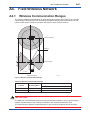
Field Wireless Network...........................................................................A4-1
A4.1
Wireless Communication Ranges................................................................ A4-1
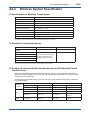
A4.2
Wireless System Specification..................................................................... A4-2
IM 01W01F01-01EN
Toc-3
PART-B ENGINEERING
B1.
Engineering..............................................................................................B1-1
B1.1
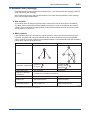
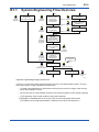
System Engineering Flow Overview............................................................. B1-2
B1.2
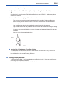
Basics............................................................................................................... B1-4
B1.2.1
Preparations......................................................................................B1-5
B1.2.2
Field Wireless Network Offline Engineering.....................................B1-7
B1.2.2.1 Creating a Project Database...........................................B1-7
B1.2.2.2 Registering YFGW710.....................................................B1-9
B1.2.2.3 Registering Field Wireless Device.................................B1-12
B1.2.2.4 Loading a Capabilities File (CF)....................................B1-12
B1.2.2.5 User Application Engineering........................................B1-14
B1.2.3
Work before Installing Field Wireless Device.................................B1-16
B1.2.3.1 Task of Setting YFGW710.............................................B1-16
B1.2.3.2 Task of Provisioning a Field Wireless Device................B1-18
B1.2.3.3 Adjusting and Setting Field Wireless Device
Parameters....................................................................B1-20
B1.2.4
Downloading to YFGW710.............................................................B1-20
B1.2.4.1 Registering Provisioning Information with
the Project Database.....................................................B1-20
B1.2.4.2 Downloading to YFGW710............................................B1-24
B1.2.5
Task of Checking Field Wireless Network Operation Conditions...B1-27
B1.2.5.1 Checking Join Status of Field Wireless Devices
to Field Wireless Network..............................................B1-27
B1.2.5.2 Checking Client/Server Communication between
YFGW710 and Field Wireless Device...........................B1-28
B1.3
B1.2.6
Task of Setting and Adjusting Field Wireless Device
Parameters.....................................................................................B1-29
B1.2.7
Task of Downloading the Process Data Communication
Definitions.......................................................................................B1-29
B1.2.8
Engineering of Control System.......................................................B1-32
Applications................................................................................................... B1-33
B1.3.1
Field Wireless Device Maintenance Task.......................................B1-33
B1.3.1.1 Task of Replacing a Field Wireless Device...................B1-33
B1.3.1.2 Task of Replacing YFGW710........................................B1-35
B1.3.1.3 Monitoring Field Wireless Device Status.......................B1-36
B1.3.2
Network Construction Task.............................................................B1-37
B1.3.2.1 Setting Device Role.......................................................B1-37
B1.3.2.2 Time Synchronization
(Connection with an NTP Server)..................................B1-40
B1.3.3
System Expansion..........................................................................B1-41
B1.3.3.1 Connecting with an OPC Server...................................B1-41
B1.3.3.2 Constructing Multiple Field Wireless Networks.............B1-42
B1.3.3.3 Security..........................................................................B1-43
IM 01W01F01-01EN
Toc-4
B2.
System Maintenance...............................................................................B2-1
B2.1
Alarm................................................................................................................ B2-1
B2.2
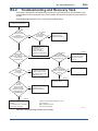
Troubleshooting and Recovery Task............................................................ B2-2
IM 01W01F01-01EN
Toc-5
PART-C ATTACHED SOFTWARE
C1.
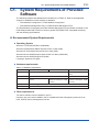
System Requirements of Provided Software.......................................C1-1
C2.
Field Wireless Configurator ..................................................................C2-1
C2.1
C2.2
C2.3
Introduction..................................................................................................... C2-1
C2.1.1
Document Purpose and Intended Users......................................... C2-1
C2.1.2
Product Overview............................................................................ C2-1
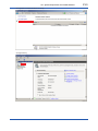
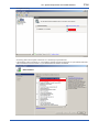
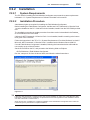
Installation....................................................................................................... C2-2
C2.2.1
System Requirements..................................................................... C2-2
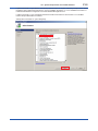
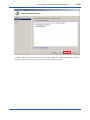
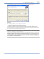
C2.2.2
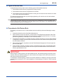
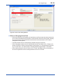
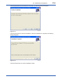
Installation Procedure...................................................................... C2-2
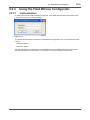
Using the Field Wirless Configurator .......................................................... C2-5
C2.3.1
Authentication.................................................................................. C2-5
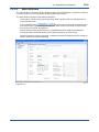
C2.3.2
Main Window................................................................................... C2-6
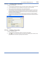
C2.3.3
Working with Projects...................................................................... C2-7
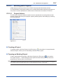
C2.3.3.1 Project Actions................................................................ C2-7
C2.3.3.2 Project Properties........................................................... C2-9
C2.3.3.3 Options.......................................................................... C2-10
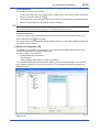
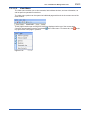
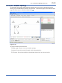
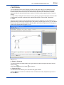
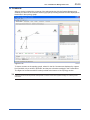
C2.3.3.4 Creating a Project..........................................................C2-11
C2.3.3.5 Downloading Project Data to the YFGW710................ C2-19
C2.3.3.6 Error Checks ................................................................ C2-23
C2.3.3.7 Download Status.......................................................... C2-24
C2.3.3.8 Download History.......................................................... C2-25
C2.3.3.9 Project Log.................................................................... C2-26
C2.3.4
How To…........................................................................................ C2-28
C2.3.4.1 Modifying a Project....................................................... C2-28
C2.3.4.2 Add a Device to an Existing Project.............................. C2-28
C2.3.4.3 Delete One or More Devices........................................ C2-29
C2.3.4.4 Modifying a device........................................................ C2-29
C2.3.4.5 Replacing YFGW710.................................................... C2-29
C2.3.4.6 Modifying Sampling Parameters.................................. C2-29
C2.3.4.7 Modifying the Modbus Register Map............................ C2-30
C2.3.5
Users.............................................................................................. C2-30
C2.3.5.1 User Accounts............................................................... C2-31
C2.3.5.2 Changing your password.............................................. C2-33
C2.3.6
Help Menu...................................................................................... C2-33
IM 01W01F01-01EN
Toc-6
C3.
Field Wireless Management Tool..........................................................C3-1
C3.1
C3.2
C3.3
Introduction .................................................................................................... C3-1
C3.1.1
Document Purpose and Intended Users......................................... C3-1
C3.1.2
Product overview............................................................................. C3-1
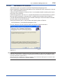
Installation....................................................................................................... C3-1
C3.2.1
System Requirements..................................................................... C3-1
C3.2.2
Installation Procedure...................................................................... C3-2
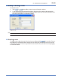
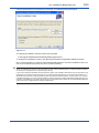
Using the Field Wireless Management Tool................................................. C3-5
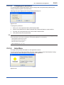
C3.3.1
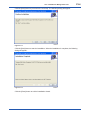
Authentication and Connection to YFGW710................................. C3-5
C3.3.1.1 Creating a New Connection............................................ C3-6
C3.3.1.2 Deleting a Connection.................................................... C3-6
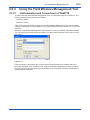
C3.3.2
Main Window................................................................................... C3-7
C3.3.2.1 Action Menu.................................................................... C3-8
C3.3.2.1.1 Connecting to/Disconnecting from YFGW710........ C3-8
C3.3.2.1.2 Viewing the System Status (YFGW Status)............ C3-8
C3.3.2.1.3 Upgrading the System (System Upgrade).............. C3-9
C3.3.2.1.4 Changing Your Password (Change Password).... C3-10
C3.3.2.2 View Menu.....................................................................C3-11
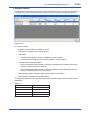
C3.3.2.2.1 Network Topology.................................................. C3-12
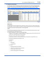
C3.3.2.2.2 Network Health...................................................... C3-17
C3.3.2.2.3 Devices.................................................................. C3-19
C3.3.2.2.4 Readings............................................................... C3-34
C3.3.2.2.5 Commands Log..................................................... C3-35
C3.3.2.2.6 User Accounts....................................................... C3-37
C3.3.2.3 Help Menu..................................................................... C3-39
C4.
Restriction of function............................................................................C4-1
C4.1
Field Wireless Configurator........................................................................... C4-1
C4.1.1
Notice of Error Checks for Number of connected field wireless
devices and Publication period (Update time)................................. C4-1
IM 01W01F01-01EN
i
<Read Me First>
Introduction
This document describes engineering related procedures including the installation and
wiring of YFGW710 Field Wireless Integrated Gateway and the setting and start-up of field
wireless networks through YFGW710. YFGW710 Field Wireless Integrated Gateway is a
core component of field wireless networks conforming to ISA100.11a, the wireless communication standard for industrial automation prescribed by the International Society of
Automation (ISA).
IMPORTANT
This manual consists of the following four parts.
l Part A Hardware of YFGW710
This part explains the hardware specifications, installation, wiring, and maintenance works for the
YFGW710 Field Wireless Integrated Gateway, and the specifications of the wireless network.
Part B Engineering
This part explains the procedure for engineering work to build up and operate the Field Wireless
System.
Part C Attached Software
This part explains the procedure of installation and operation of the Field Wireless Configurator
and the Field Wireless Management Tool. Both programs are attached to YFGW710 and referred
to from Part B Engineering as necessary.
Field Wireless Configurator: sets up the field wireless system and its element devices
Field Wireless Management Tool: manages the operation of the field wireless system
And this part explains the precautions of hardware and software.
IM 01W01F01-01EN
ii
<Read Me First>
Safety Precautions
IMPORTANT
Be sure to read the safety precautions for this product described in Read Me First (IM
01W01F01-11EN).
n Transportation of products containing lithium batteries :
This product contains lithium batteries. Primary lithium batteries are regulated in transportation
by the U.S. Department of Transportation, and are also covered by the International Air Transport Association (IATA), the International Civil Aviation Organization (ICAO), and the European
Ground Transportation of Dangerous Goods (ARD). It is the responsibility of the shipper to
ensure compliance with these or any other local requirements. Consult current regulations and
requirements before shipping.
n How to dispose the batteries:
This is an explanation about the new EU Battery Directive (DIRECTIVE 2006/66/EC).This directive is only valid in the EU.
Batteries are included in this product. Batteries incorporated into this product cannot be removed
by yourself. Dispose them together with this product.
When you dispose this product in the EU, contact your local Yokogawa Europe B.V. office. Do not
dispose them as domestic household waste.
Battery type: lithium thionyl chloride primary battery
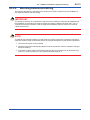
CAUTION
The symbol (see above) means they shall be sorted out and collected as ordained in ANNEX II in
DIRECTIVE 2006/66/EC.
IM 01W01F01-01EN
iii
<Read Me First>
n Cautions for Safely Applying the Device:
l EMC Conformity Standards
EN61326-1 Class A, Table 2 (For use in industrial locations), EN61000-6-2
CAUTION
This instrument is a Class A product, and it is designed for use in the industrial environment.
Please use this instrument in the industrial environment only.
l Low Voltage Directive
Applicable standard: EN61010-1
(1) Pollution Degree 2
“Pollution degree” describes the degree to which a solid, liquid, or gas which deteriorates dielectric strength or surface resistivity is adhering. “2” applies to normal indoor atmosphere. Normally,
only non-conductive pollution occurs. Occasionally, however, temporary conductivity caused by
condensation must be expected.
(2) Installation Category I
“Overvoltage category (Installation category)” describes a number which defines a transient overvoltage condition. It implies the regulation for impulse withstand voltage.
“I” applies to electrical equipment which is supplied from the circuit when appropriate transient
overvoltage control means (interface) are provided.
l Regulatory Compliance for Radio and Telecommunication
Please confirm that a installation region fulfils a standards, require additional regulatory information and approvals, contact to Yokogawa Electric Corporation.
• Radio and Telecommunications
Terminal Equipment Directive (R&TTE)
We, Yokogawa Electric Corporation hereby declare that this equipment, YFGW710 is in compliance with the essential requirements and other relevant provisions of Directive 1999/5/EC.
The CE declaration of conformity for R&TTE for this product can be found at http://www.
yokogawa.com/fld/
NOTE
France restricts outdoor use to 10 mV (10 dBm) EIRP in the frequency range of 2,454 -2,483.5 MHz.
Installation in France must configure the network with configuration tool not to use channel 10 to
14. To configure the network, refer to Part C and Part D of this document.
IM 01W01F01-01EN
iv
<Read Me First>
l FCC compliance
This device complies with Part 15 pf FCC Riles. Operation is subject to the following two conditions: (1) this device may not cause interference, and (2) this device must accept any interference, including interference that may cause undesired operation of this device.
Co-located:
This transmitter must not be co-located or operated in conjunction with any other antenna or
transmitter.
FCC WARNING:
Changes or modifications not expressly approved by the party responsible for compliance could
void the use’s authority to operate the equipment.
NOTE
This equipment has been tested and found to comply with the limits for a Class A digital device,
pursuant to part 15 of the FCC Rules. These limits are designed to provide reasonable protection
against harmful interference when the equipment is operated in commercial environment.
This equipment generates, uses, and can radiate radio frequency energy and, if not installed and
used in accordance with the instruction manual, may cause harmful interferences to radio communications. Operation of this equipment in a residential area is likely to cause harmful interference in which case the user will be required to correct the interference at his own expense.
l Industry Canada (IC) compliance
This Class A digital apparatus complies with Canadian ICES-003.
French: Cet appareil numérique de la class A est conforme à la norme NMB-003 du Canada.
Operation is subject to the following two conditions: (1) this device may not cause interference,
and (2) this device must accept any interference, including interference that may cause undesired operation of the device.
n Insulation Resistance and Dielectric Strength Test
Insulation Resistance and dielectric strength test could not be carried out for YFGW710, due to
the circuit ground is connected directly to the frame of YFGW710 via RF cable shield.
IM 01W01F01-01EN
v
<Read Me First>
Documentation Conventions
n Typographical Convention
The following typographical conventions are used throughout the user’s manuals:
Conventions commonly used throughout user’s manuals
Character string to be entered
The characters to be entered are shown in one-byte characters as follows:
Example:
FIC100.SV=50.0
“”Mark
Indicates a space between character strings to be entered.
Example:
.AL PIC010 -SC
Character string enclosed by brackets ({ })
Indicates an option that can be omitted.
Example:
.PR TAG {. Sheet name}
Conventions used to show key or button operations:
Characters enclosed by brackets ([ ])
Characters enclosed by brackets within any description on a key or button operation, indicate
either a key on the HIS (Human Interface Station) keyboard, a key on the operation keyboard, a
button name on a window, or an item displayed on a window.
Example:
To alter the function, press the [ESC] key
Characters enclosed by angle-brackets (<>)
Characters enclosed by angle-brackets show the title of the screen during the explanation of the
software operation.
IM 01W01F01-01EN
vi
<Read Me First>
Conventions used in command syntax or program statements:
The following conventions are used in a command syntax or program statement:
Characters enclosed by angle-brackets
Indicate character strings that user can specify freely according to certain guidelines.
Example:
#define <Identifier><Character string>
“...” Mark
Indicate that the previous command or argument may be repeated.
Example:
Imax (arg1, arg2, ...)
Characters enclosed by brackets ([ ])
Indicate that those character strings can be omitted.
Example:
sysalarm <format_string> [output_value ...]
Characters enclosed by separators (| |)
Indicate that those character strings can be selected from more than one option.
Example:
opeguide <format_character_string> [, <output_value> ...]
OG,<element number> opeguide
n Symbols used in the manual
The symbol used in the manual are described in “Read Me First” (IM 01W01F01-11EN).
n Drawing Conventions
Some drawings may be partially emphasized, simplified, or omitted, for the convenience of description.
Some screen images depicted in the user’s manual may have different display positions or
character types (e.g., the upper/lower case). Also note that some of the images contained in this
user’s manual are display examples.
IM 01W01F01-01EN
vii
<Read Me First>
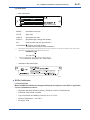
Information of User’s Manual Revision
Material Name: YFGW710 Field Wireless Integrated Gateway
Material Number: IM 01W01F01-01EN
Edition
Date
Page
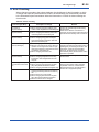
Revised Item
1st
August 2010
New Issue
2nd
October 2010
A3-24
Add “Explosion Proof Certifications.”
3rd
April 2011
v
A3-24
B1-2
B1-4
Added “Use of Open Source License Software”
Added electrical connection code 0
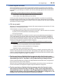
Modified the System Engineering Flow Overview figure
Added note regarding setting device information using infrared
communications in FieldMate R2.03.00
Deleted “Restriction of changing Defining Device Role”
Deleted “Notice of saving a project as different name”
D3
4th
September 2011
PART-A
PART-D
Corrections made.
Deleted.
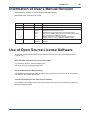
Use of Open Source License Software
This product uses software based on the open source license of GPL (GNU General Public
License), etc.
GPL (the GNU General Public License) Provisions
For details on the GPL, see the following URL.
URL http://www.gnu.org/copyleft/gpl.html
Scope of Warranty and Responsibility
Yokogawa does not guarantee the operation of the open source software itself in accordance
with the GPL and related provisions.
Individual Information of the Open Source Software
For details on the module names and source codes of the open source software, contact your
nearest Yokogawa dealer.
IM 01W01F01-01EN
<Read Me First>
viii
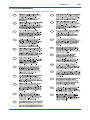
n ATEX Documentation
This is only applicable to the countries in European Union.
GB
DK
SK
CZ
I
LT
E
LV
NL
EST
PL
SF
SLO
P
H
F
BG
D
RO
S
M
GR
IM 01W01F01-01EN
<A1. Introduction>
A1-1
A1. Introduction
The YFGW710 Field Wireless Integrated Gateway and field wireless devices are used to build an
industrial wireless network that conforms to ISA100.11a, the wireless communication standard
for industrial automation specified by the International Society of Automation (ISA).
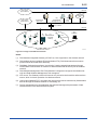
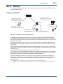
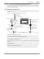
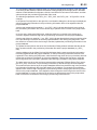
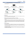
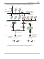
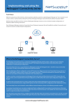
As shown in Fig. A1-1, the YFGW710 Field Wireless Integrated Gateway plays a key role in the
wireless network and has the following functions:
• Allows field wireless devices to join the wireless network, forms and maintains communication routes, and manages the wireless network for monitoring the communication state
• Stores Publish*1 data of field wireless devices in the Modbus register for transmitting it to
CENTUM VP or other host systems
• Transmits process data to the host system via a Modbus/TCP or dedicated OPC server
• Relays on-demand communication for parameter setting and management between field
wireless devices and PRM
*1: Action to measure the process value at intervals preset in the field wireless device itself and transmit it via wireless communication
This manual explains the YFGW710 Field Wireless Integrated Gateway (hereinafter referred to
as YFGW710) and the field wireless network.
Among field wireless devices, our wireless EJX (Differential Pressure/Pressure Transmitter) and
wireless YTA (Temperature Transmitter) can communicate with the YFGW710. Devices certified
as compliant with the ISA100.11a standard can communicate with the YFGW710 and join the
wireless network.
For details of field wireless devices, refer to the user’s manual of the respective devices.
For the overall system configuration including the field wireless network and a host system, refer
to the general specifications:
GS 01W01A01-01EN Overview of Field Wireless System
IM 01W01F01-01EN
A1-2
<A1. Introduction>
Host system
(OPC interface)
Ethernet
(7)
(6)
(4)
Field Wireless
OPC server
Host system
(Modbus/TCP)
Field Wireless
Management Tool
Device
management
tool
(5)
NTP
server
Ethernet
Layer 3 switch
Ethernet
(3)
(1)
Field Wireless
Integrated
Gateway
(2)
FieldMate
EJX
Ir connection
YTA
Field Wireless Network
Ir adapter
FA0101.ai
Figure A1-1 Image of Field Wireless Network
Notes:
(1) Field Wireless Integrated Gateway (YFGW710): Core equipment in the wireless network
(2) Field wireless devices (wireless EJX and wireless YTA): Field instruments that measure
process values and send them wirelessly
(3) FieldMate: Software that performs “provisioning” (setting essential parameters) through
infrared data communication in advance to allow wireless field devices to join the wireless
network
(4) Field Wireless Management Tool: Field Wireless Configurator configures the wireless network and Field Wireless Management Tool manages it.
(5) NTP server: The Gateway refers to this server to synchronize its time with a reference time
source, which is a basic operation of a wireless network.
(6) Host system (Modbus/TCP): A system that uses process values measured by field wireless
devices through the wireless network for monitoring, etc.
(7) Device management tool: An application that sets and manages the parameters of field
wireless devices via a wireless network system
IM 01W01F01-01EN
A2-1
<A2. Checking the Product>
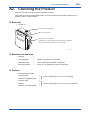
A2. Checking the Product
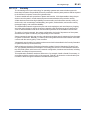
When you receive the product, please check the contents.
Check that the product specifications match your order, all parts are included, and there is no
damage, stains, or other troubles.
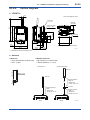
n Main unit
• YFGW710
Antenna connector (Capped)
Main unit of YFGW710
Bracket on the housing side
Provided when “2-inch (2B) pipe mounting bracket” is specified.
The bracket is secured to the main unit with screws.
FA0201.ai
n Standard accessories
• Antenna
1
• User’s Manual
1
English or Japanese, as specified
• Software media
1
When “With Software Media” is specified
• Mounting bracket
1
When “2-inch (2B) pipe mounting” is specified
n Options
• External antenna cable
Antenna cable
1
Antenna mounting bracket
1
Antenna cable
2
Arrester
1
Antenna mounting bracket
1
When “cable length: 1 m or 3 m” is specified
When “cable length: 4 m, 6 m or 13 m” is specified
IM 01W01F01-01EN
<A3. YFGW710 Field Wireless Integrated Gateway>
A3-1
A3. YFGW710 Field Wireless Integrated
Gateway
This chapter explains the installation of the YFGW710, antennas, cable connections, and maintenance.
A3.1 Installation
A3.1.1
Requirements for Installation Locations
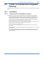
The installation of YFGW710 and field wireless devices must meet the following conditions:
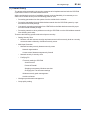
• The field wireless equipment should be mounted in the place where no obstacle exists
around the antenna. Especially, YFGW710 should be mounted in the condition that no obstacle exists around the antenna, in both cases of wall mounting and pipe mounting.
• If there is a pipe for mounting or plumbing in the direction except for the communication
partners, the antenna should be more than 30 cm apart from them.
• When the wall mounting does not satisfy the condition, use the extension cable to mount an
antenna in the place where there is no influence from any objects.
• All antennas must be in the upright position.
• The antenna of field wireless equipment must be installed at least 1.5 meter above the
ground (floor)
• The YFGW710 should be installed at a location as close as possible to the center of the field
wireless network.
• Ensure that the field wireless devices that are located within the wireless communication
range are within the line of sight of each other. In the star topology, the YFGW710 must
meet this condition.
IM 01W01F01-01EN
<A3. YFGW710 Field Wireless Integrated Gateway>
A3-2
Extension
Cable
More than
1.5 m
2-inch (2B) pipe
Wall Mounting
FA0301.ai
Figure A 3-1 Mounting Example of Field Wireless Integrated Gateway
A3.1.2
Notes on Installation
Pay attention to the following points at the installation of YFGW710.
Installation Location
This device is designed to work under the severe environmental condition. However, it is necessary to pay attention to the following conditions for the stable and long-term precise operation.
Exposure to Direct Sunlight
If the device is placed at a location that may be exposed to direct sunlight, it is necessary
to make the insulation measure. However, the antenna must be covered with the material
which does not block the radio wave.
Ambient Temperature
Avoid locations subject to wide temperature variations or a significant temperature gradient.
If the location is exposed to radiant heat from plant equipment, provide adequate thermal
insulation and/or ventilation. Do not install the device in a location where high temperature
and high humidity may last for a long time.
Ambient Atmosphere
Do not install the device in a corrosive atmosphere. If this cannot be avoided, there must
be adequate ventilation as well as measures to prevent the rain water from penetrating or
remaining in the conduits.
IM 01W01F01-01EN
<A3. YFGW710 Field Wireless Integrated Gateway>
A3-3
Vibration and Impact
Although the device is designed to be resistant to vibration and impact, an installation site
should be selected where vibration and impact are kept to a minimum.
Installation of Explosion Proof Compliant Device
The explosion proof compliant equipment can be installed in the hazardous area of specific
gases. This device must be installed in accordance with the regulations of the country where the
device is installed.
• Installation: Check that the ambient temperature is not beyond the limit.
• Wiring: Put all the power cables in protective ducts. If possible, also put the network cables
(optical fiber cable or metal cable) in protective ducts.
• Maintenance: After confirming that there is no dangerous gas in the ambience, open the
housing or protective ducts.
A3.1.3
Mounting Procedure
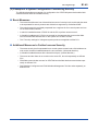
Mount YFGW710 on the 2-inch (2B) pipe or the wall where the environment satisfies all the requirements for the wireless device.
SEE
ALSO
For more information about the installation environment, see the General Specification of YFGW710 Field Wireless Integrated Gateway (GS 01W01F01-01EN).
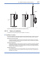
Mounting to 2-inch (2B) Pipe with Bracket
When mounting the device on the 2-inch (2B) pipe, a dedicated bracket should be used. This
bracket is an option of YFGW710, see the model code list.
This bracket does not support the mounting to the horizontal piping.
Bracket
2-inch (2B) pipe
FA0302.ai
Fig. A 3-2 Mounting YFGW710 to 2-inch (2B) pipe
IMPORTANT
YFGW710 is a heavy device (5.1 kg). Ensure that the bracket and 2-inch (2B) pipes used for
mounting are fixed firmly enough to withstand strong wind and vibration. The device must be
maintained in its upright position.
IM 01W01F01-01EN
A3-4
<A3. YFGW710 Field Wireless Integrated Gateway>
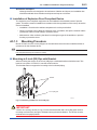
Mounting procedure
1.
Fix the bracket 1 for the housing to the back of Gateway with the 4 provided screws. When
you specify a unit with the bracket, the bracket is secured to the main body with screws.
2.
Screw the 4 provided bolts into the bracket 1 as shown in the figure.
3.
Hold 2-inch (2B) pipe by the bracket 1 and bracket 2, and tightly fasten the bolts with nuts.
2-inch (2B) pipe
Bracket 2
Bracket 1 for housing
Washer
Screw
Bolt
Washer
Nut
FA0303.ai
Fig. A 3-3 Mounting to the 2-inch (2B) pipe
IM 01W01F01-01EN
A3-5
<A3. YFGW710 Field Wireless Integrated Gateway>
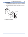
Mounting to the Wall Using Bracket
When mounting YFGW710 to the wall, use the bracket for the housing. When the body is ordered, the bracket is specified by the model code. To avoid the communication problem caused
by the wall, mount the Gateway in the place where any obstacles do not exist around the antenna.
When no place satisfying the mounting condition, the antenna should be mounted in an appropriate place apart from the main body using the extension cable.
Mounting Procedure
1. Fix the bracket for the housing using the 4 provided screws on the back of Gateway
2. Fix the Gateway to the wall using M5 screws through screw holes.
3. To avoid the vibration and wind and so on, fix the antenna on the place apart from the wall
and obstacles according to the procedure described in A3.2.4.
Mount the main body on the wall with the
bracket and M5 screws.
The provided bolts and nuts are not used.
126.5
Ø6.5 hole
or M5 Screw
190
FA0304.ai
Fig. A 3-4 Mounting to the wall
IM 01W01F01-01EN
<A3. YFGW710 Field Wireless Integrated Gateway>
A3.1.4
A3-6
Set-up after Mounting
The necessary procedure after mounting YFGW710 is explained.
Attaching Cable Glands
Attach the cable glands to the housing before connecting the cables to YFGW710 as necessary.
The left cable gland is for the communication cable and the right one is for the power supply
cable (see the label on the bottom of main housing).
Cable Gland
for Communication
Cable Gland
for Power Supply
FA0305.ai
Fig. A 3-5 Attaching Cable Gland
IM 01W01F01-01EN
A3-7
<A3. YFGW710 Field Wireless Integrated Gateway>
Opening and Closing Front Door
Open and close the front door of the housing following the procedure below.
Close
Four bolts to fix the front door
Open
FA0306.ai
Fig. A 3-6 How to open/close the front door
How to open the front door
1. Unscrew the four M5 Hexagon socket head cap bolts at each corner of the front door. The
bolts do not get away from the screw hole. Use a hex wrench of 4 mm hexagon width across
flats to unscrew/tighten the bolts.
2. Open the door to the left.
How to close the front door
1. Close the front door to the main housing with full attention not to get fingers pinched in the
hinge and between the front door and the main housing.
2. Tighten the four fixing bolts pressing the right edge of the front door evenly with a torque of
2.8 N∙m ±0.2 N∙m.
IMPORTANT
When opening and closing the front door, be careful not to get fingers and/or a part of body
pinched in the hinge and/or between the door and the main unit.
IM 01W01F01-01EN
A3-8
<A3. YFGW710 Field Wireless Integrated Gateway>
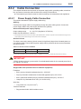
A3.2 Cable Connection
This chapter describes the connection of the power supply cable, grounding cable, network cable, and antenna extension cable and also the mounting of the antenna.
The explosion proof device must be wired according to the related laws and regulations.
A3.2.1
Power Supply Cable Connection
This section describes the power supply cable wiring.
Wiring
Pull the power supply cable into the gateway through the power cable ground. Connect the
power supply cable to the power supply terminal in the gateway.
Recommended power supply capacity
Output voltage range
12 – 24 V DC (Supplied to YFGW710)
Output Current More than 1.5 A DC *1
*1: This equipment flows the inrush current at start-up as explained below. Therefore, the power source should have enough current
output capacity several times as high as the normal current consumption.
Inrush Current
The input current at the start up (inrush current) is significantly larger than the steady state current (see the table). Ensure that the power supply and its protective device can accommodate
this inrush current.
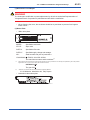
Table A 3-1 Inrush current of YFGW710
Item
Inrush Current
Specification
30 A 2 ms
*2
Remarks
at 24 V DC
*2: This note corresponds when the power line breaker of YFGW710 is turned-on in condition the power source is running.
IMPORTANT
YFGW710 does not have a power switch. Set a dedicated breaker for the external power line to
turn ON/OFF the device.
Applicable Cable (Insulated wire for industrial equipment)
Examples:
• 600 V polyvinyl chloride insulated wires (IV): JIS C3307
• Polyvinyl chloride insulated wires for electrical apparatus (KIV): JIS C3316
• 600 V grade heat-resistant polyvinyl chloride insulated wires (HIV): JIS C3317
• Heatproof vinyl insulated wires VW-1 (UL1015/UL1007)
Wire Size
• Core: AWG14 to 13 (2 to 2.6 mm2)
Terminal Treatment
• Ring terminal for M4: With insulation covers
IM 01W01F01-01EN
A3-9
<A3. YFGW710 Field Wireless Integrated Gateway>
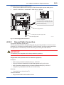
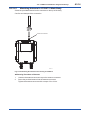
Connection Procedure of Power Cable
1.
Pull the power cable into the housing of YFGW710 through the power cable ground.
2. Connect + lead wire to + terminal and – lead wire to – terminal.
SUPPLY
Connect the + and – wires to the + and –
terminals, respectively.
If the power cable is a shielded cable, the
shield should be grounded at terminal and
the grounding of the whole cable should be
restricted to this point only.
ANTENNA 50Ω
NETWORK
(Optional)
100Base-FX
TX
SUPPLY
100Base-FX
RX
Power supply terminal
Cable gland for power supply cable
Power supply cable
FA0307.ai
Fig. A 3-7 Power Supply Cable Connection
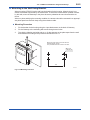
A3.2.2
Ground Cable Connection
This section describes ground wiring.
Class D grounding (the third class grounding) with the grounding resistance of 100 Ω or less is
necessary. To connect the grounding cable to YFGW710 directly, use the grounding terminal on
the right bottom of the main body. Do not share the ground wiring with other devices.
IMPORTANT
The explosion proof compliant device always needs the grounding.
Applicable Cable (Insulated wire for industrial equipment)
Examples:
• 600 V polyvinyl chloride insulated wires (IV): JIS C3307
• Polyvinyl chloride insulated wires for electrical apparatus (KIV): JIS C3316
• 600 V grade heat-resistant polyvinyl chloride insulated wires (HIV): JIS C3317
• Heatproof vinyl insulated wires VW-1 (UL1015/UL1007)
Wire Size
• Core: AWG14 to 13 (2 to 2.6 mm2)
Terminal Treatment
• Ring terminal for M4: With insulation covers
IM 01W01F01-01EN
A3-10
<A3. YFGW710 Field Wireless Integrated Gateway>
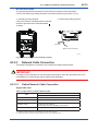
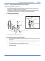
Connection of Cable
The grounding terminals are located on the inside and outside of the terminal area.
Connect the cable to grounding terminal in accordance with wiring procedure 1) or 2).
1) Internal grounding terminal
2) External grounding terminal
If the power cable is a shielded cable, the shield
should be grounded at the terminal marked
as below.
M4 screw
(Bottom of the enclosure)
FA0308.ai
Fig. A 3-8 Wiring Procedure for Grounding Terminals
A3.2.3
Network Cable Connection
This section describes the connection of the optical and metal network cables.
IMPORTANT
According to the requirement of communication specification, select the optical Ethernet or the
metal Ethernet to communicate with the higher layer application.
A3.2.3.1
Optical Network Cable Connection
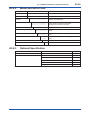
Applicable Cable
Table A 3-2 Specification of Optical Network Cable
Specification
Item
Optical Fiber Cable
Standard
100Base-FX*1
Connector
SC Connector (1-pole x 2)*2
Applicable Cable
Multi Mode Fiber (Central wavelength: 1300 nm)
50/125 um or 62.5/125 um
Inner tension must be nonmetals, such as FRP.
Transmission Range
2 km (Max.)
*1: 100Base-TX (Refer table A3-3) and 100Base-FX must be used exclusively.
*2: A double ferrule SC connector cannot be used. Be sure to use a single ferrule type.
IM 01W01F01-01EN
<A3. YFGW710 Field Wireless Integrated Gateway>
A3-11
IMPORTANT
The connection between the host system (CENTUM or STARDOM equipment and other application PCs) and YFGW710 requires an optical to metal Ethernet converter. Prepare an appropriate
converter which matches respective communication specifications for converting 10BASET/100BASE-TX and 100BASE-FX. The recommended model is SLX-5ES-2SC of SIXNET.
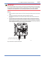
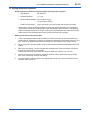
Wiring
1.
Pull the optical fiber network cable into YFGW710 through the cable ground for the network
cable.
2. Connect the optical fiber communication cable to the optical connector.
Do not bend the optical fiber communication cable at a tight angle; arrange it as shown in
the figure.
3. The optical fiber communication cable is composed of a pair of wires that are used separately and exclusively for transmission and reception (TX/RX), as indicated on the internal
label of the pole of SC optical connector into YFGW710. Follow the indication on the label, if
shown. If there is no indication, you may connect them arbitrarily. The connection directions
can be changed easily in the optical converter of the host system.
ANTENNA 50Ω
NETWORK
(Optional)
100Base-FX
TX
Cable Gland for Network Cable
SUPPLY
100Base-FX
RX
SC Optical Connecter
Optical Fiber communication cable
FA0309.ai
Fig. A 3-9 Connection of optical network cable
IM 01W01F01-01EN
<A3. YFGW710 Field Wireless Integrated Gateway>
A3.2.3.2
A3-12
Metal Network Cable Connection
Caution for Use of Metal Network Cable
The metal network cable is for indoor operations only. To use it outdoors, the arrester is needed.
However, there is no appropriate arrester of the outdoor specification which can be installed
close to YFGW710.
Therefore, use the optical fiber network cable for the outdoor wiring.
Applicable Cable
Table A 3-3 Specification of Metal Network Cable
Specification
Item
Metal Network Cable
Standard
100Base-FX*1
Connector
RJ-45*2
Applicable Cable
Category 5 or higher
Transmission Range
100 m (Max.)
*1: 100Base-TX and 100Base-FX (Refer table A3-2) must be used exclusively.
*2: RJ-45 connector must be connected to YFGW710 after putting the cable through the cable ground.
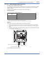
Wiring
Connect the metal network cable according to the following procedure.
1. Pull the metal network cable into YFGW710 through the cable ground for network cable.
2. Apply pressure welding to connect the RJ-45 connector and the end of the metal network
cable.
3. Connect the metal network cable to the network connector. Use the metal cable conforming
to the standard of 100BASE-TX.
ANTENNA 50Ω
NETWORK
(Optional)
100Base-FX
TX
SUPPLY
100Base-FX
RX
Cable Ground for Network Cable
Ethernet Connector
Metal Network Cable
FA0310.ai
Fig. A 3-10 Metal network cable connection
IM 01W01F01-01EN
<A3. YFGW710 Field Wireless Integrated Gateway>
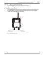
A3.2.4
A3-13
Mounting Antenna and Wiring
This section describes the mounting of the antenna to YFGW710 main body, the installation of
the external antenna, and their wiring.
IMPORTANT
The antenna connector is covered with a cap at the time of delivery. Keep the cap attached until
the installation of the antenna or antenna cables to protect the inside connection part. The unscrewed cap should be stored in order to replace it immediately after the antenna or antenna
cables are removed.
NOTE
To maintain the ultimate conditions of radio-frequency signal, protect the connectors of antenna,
extension antenna cable, and arrester from the corrosive atmosphere by the following treatment.
1. Clean the connection to be protected.
2. Wind the butyl rubber self-bonding tape around the connection. See the manual of the tape
about the winding.
3. To protect the butyl rubber self-bonding tape from the environment such as ultraviolet rays
and so on, wind vinyl tape (or a vinyl type self-bonding tape) on it.
IM 01W01F01-01EN
A3.2.4.1
<A3. YFGW710 Field Wireless Integrated Gateway>
A3-14
Mounting Antenna to YFGW710 Main Body
Screw the provided antenna into the connector on the top of the body.
Confirm and waterproof the connection.
Antenna connector
FA0311.ai
Fig. A 3-11 Mounting the antenna to the housing of YFGW710
Mounting Procedure of Antenna
1.
Unscrew the antenna connector cap on the antenna connector.
2.
Screw the provided antenna into the antenna connector.
Tighten the antenna connector with a torque of 2 to 3 N∙m.
IM 01W01F01-01EN
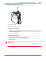
A3.2.4.2
A3-15
<A3. YFGW710 Field Wireless Integrated Gateway>
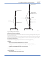
Mounting and Wiring External Antenna
Mounting of External Antenna
Mount the external antenna at the proper location according to the wireless environment described in “A3.1.1 Installation Condition” of this manual.
The mounting to the pipe such as 2-inch (2B) pipe needs to secure the enough strength to endure a strong wind, vibration and so on. The antenna must be mounted vertically.
Fixing of External Antenna
Fix an external antenna appropriately using the bracket provided as the external antenna option.
External Antenna
2-inch (2B) pipe
2-inch (2B) pipe
Bracket
External Antenna
U Bolt
Antenna Extension Cable
Nut
Washer
Bracket 2
Antenna Extension Cable
Bracket 1
Washer
Nut
FA0313.ai
Fig. A 3-12 Example of fixing external antenna
Mounting Procedure of External Antenna
1.
Fix the antenna extension cable to the bracket 1 with the provided nut as shown in the figure
A3-12 above.
2.
Fix the bracket 1 to the 2-inch (2B) pipe by using the provided a pair of U bolts and bracket 2.
3.
Screw the antenna into the antenna connector of the antenna extension cable on the
bracket 1.
Tighten the antenna connector with a torque of 2 to 3 N∙m.
4. Protect the connection as necessary. For details of the protection, see “A3.2.4 Mounting
Antenna and Wiring.”
IM 01W01F01-01EN
<A3. YFGW710 Field Wireless Integrated Gateway>
A3-16
Wiring External Antenna
Specification for Extension Antenna Cable (Only by order of option)
• Specification: 8D-SFA(PE)
• Outside Diameter: 11.1 mm
• Minimum Bend Radius: 67 mm (when fixing)
167 mm (when wiring)
• Cable End Treatment: N type connector, one end is male and the other is female.
* “When fixing” shows the bending radius for fixing (the state is maintained for a long time).
“When wiring” shows the bending radius while checking the wiring position. This bending
radius is set larger than that for fixing in order to prevent damage to the cable because the
cable is likely to be repeatedly bent when checking the final wiring position.
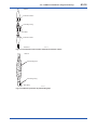
Wiring of Extension Antenna Cable
1.
Use the provided extension antenna cable to connect the antenna connector with the external antenna. Tighten the connector of the antenna extension cable with a torque of 2 to 3
N∙m. Refer to the specification about the limitation of bend radius when fixing or wiring.
2.
When using two extension cables, the provided arrester should be inserted between these
cables.
3.
Before the wiring work, confirm the polarities (male/female) of the connectors of antenna,
extension antenna cable, and arrester.
Tighten the connector of the antenna extension cable with a torque of 2 to 3 N∙m.
4.
Protect the connectors of antenna, extension antenna cable, and arrester as necessary.
See “A3.2.4 Mounting Antenna and Wiring.”
5.
Fix the extension antenna cable to the appropriate structure to protect the cable from the
vibration, wind, and so on.
IM 01W01F01-01EN
A3-17
<A3. YFGW710 Field Wireless Integrated Gateway>
External Antenna
External Antenna
Extension cable 2
Length: 10 m or 3 m
Protect by
Self-bonding tape
Arrester
Ground Wiring
Protect by
Self-bonding tape
Extension cable 1
Length: 3 m or 1 m
Extension cable
Length: 3 m or 1 m
Housing of YFGW710
Housing of YFGW710
FA0314.ai
Fig. A 3-13 Wiring of external antenna
Mounting of Arrester and Wiring
Mount an arrester between the extension cables and connect the grounding cable to the grounding terminal of the arrester.
Connect the grounding cable to the grounding terminal on the main body. Class D grounding (the
third class grounding) with the grounding resistance of 100 Ω or less is necessary. Do not share
the ground with other devices.
Applicable Grounding Cable (Insulated wire for industrial equipment)
Examples:
• 600 V polyvinyl chloride insulated wires (IV): JIS C3307
• Polyvinyl chloride insulated wires for electrical apparatus (KIV): JIS C3316
• 600 V grade heat-resistant polyvinyl chloride insulated wires (HIV): JIS C3317
• Heatproof vinyl insulated wires VW-1 (UL1015/UL1007)
Wire Size
• Core: AWG14 to 13 (2 to 2.6 mm2)
Terminal Treatment
• Ring terminal for M4: With insulation covers
IM 01W01F01-01EN
<A3. YFGW710 Field Wireless Integrated Gateway>
A3-18
Antenna
Extension cable 2
Grounding wiring
Arrester
Extension cable 1
YFGW710
FA0315.ai
Fig. A 3-14 Connection of the arrester and antenna extension cables
Antenna
Self-bonding tape
Grounding wiring
Main Body
FA0316.ai
Fig. A 3-15 Arrester protection by self-bonding tape
IM 01W01F01-01EN
<A3. YFGW710 Field Wireless Integrated Gateway>
A3-19
A3.3 Wiring for Explosion Proof
Refer to explosion proof certifications section of this document.
IM 01W01F01-01EN
<A3. YFGW710 Field Wireless Integrated Gateway>
A3-20
A3.4 Maintenance
This section describes the maintenance of YFGW710.
A3.4.1
Routine Maintenance
The following maintenance needs to be performed periodically.
IMPORTANT
If the YFGW710 is covered with dust or dirt, wipe with a soft cloth moistened by water or mild
soap.
n Antenna
When the antenna is covered with dirt or dust containing metal powder, the wireless communication may become unstable; therefore, the periodic cleaning and maintenance are necessary. In
cold regions, preventive measures against snow and ice problems as well as periodic maintenance should be provided periodically.
A3.4.2
Maintenance in Hazardous Area
Refer to explosion proof certifications section of this document.
IM 01W01F01-01EN
A3-21
<A3. YFGW710 Field Wireless Integrated Gateway>
A3.4.3
Communication Check
On the Field Wireless Network Manager, the status of wireless device connected to the wireless
network and the status of the communication route can be confirmed. Field Wireless Network
Manager is the provided software of YFGW710 and used in the PC connected to the YFGW710
of the Field Wireless System.
SEE
ALSO
For more information about checking device and communication status, see “B1.2.5 Confirmation of Field Wireless Network Operation”
A3.4.4
About Parts Having Defined Life Spans
The YFGW710 include no parts having defined life spans, which need to be replaced.
Read this section thoroughly and carry out the periodical replacement.
IMPORTANT
Precautions for parts having defined life spans
• The term “Parts having defined life spans” refers to parts that are expected to wear out or
break down within 10 years from the initial use under normal conditions of use and storage.
Therefore, parts with expected life spans of 10 years or more are excluded here.
• The recommended replacement cycle is the cycle indicated for preventive maintenance. It
provides no guarantee against the accidental failures.
• The recommended replacement cycle is merely a guideline. The actual replacement cycle
depends on the usage conditions.
The recommended replacement cycle is subject to change according to the actual results in
the field.
SEE
ALSO
For more information about installing YFGW710, see the General Specification of YFGW710 Field Wireless
Integrated Gateway (GS 01W01F01-01EN).
IM 01W01F01-01EN
<A3. YFGW710 Field Wireless Integrated Gateway>
A3-22
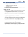
A3.5 Troubleshooting
When the malfunction occurs to the wireless communication in the start-up or during operation
and the Field Wireless Management Tool identifies that it is caused by YFGW710, follow the
procedures below.
1.
Turn off the power of YFGW710.
2.
Check the antenna connection and the wiring of power supply, communication, and grounding. Correct problems, if any. There are no other checking points which users can correct in
YFGW710.
3.
If any problems are not found but the failure remain unsolved, contact to Yokogawa’s service section in charge and request the measure such as replacing the unit.
IM 01W01F01-01EN
<A3. YFGW710 Field Wireless Integrated Gateway>
A3-23
A3.6 General Specification
A3.6.1
Standard Specification
Specification of Wireless Transmission
Item
Specification
Antenna Connector
N type
Antenna Impedance
50 ohm
For details of specification common with wireless transmission, see the table in A4.2 Wireless System Specification.
Specification of Upper Layer Interface
Item
Communication
Interface
Specification
Standard*1
100Base-TX
100Base-FX
Number of Port
1
1
Transmission Speed
100 Mbps
100 Mbps
Connector
RJ-45
SC connector (1-pole x 2)*2
Cable Type
Category5 Cable
Multimode fiber*3
50/125 or 62.5/125 μm (2-core)
Central wavelength
-
1300 nm
Transmission Range
100 m Max.
2 km Max.
Modbus/TCP
Communication
Protocol
Maximum Connection
Number*5
OPC Server for Field
Wireless*4
Proprietary Protocol
Management, Configuration, so on
Proprietary Protocol
Modbus/TCP
4 clients
OPC Server for Field
Wireless*4
10 systems
*1: 100Base-TX and 100Base-FX must be used exclusively. Use 100Base-FX for the wiring outdoors.
*2: The 2-pole SC connector cannot be put in the cable end connection.
*3: Use an optical cable with non-metal tension member for outdoor wiring.
*4: Possible to connect in the OPC interface by using OPC Server for Field Wireless (GS 33M20S20-40), which is available separately.
*5: Possible to connect at the same time.
IM 01W01F01-01EN
<A3. YFGW710 Field Wireless Integrated Gateway>
A3-24
Specification of Environment
Item
Operating Ambient
Temperature Range
-40 to +60°C
Operating Humidity Range
Power Supply
Specification
0-100%RH (without condensation)
Rating Voltage
24 V DC
Voltage Range
10.0-26.4 V DC
Instant Power Failure
Prompt shut down
Ripple
Less than 1%p-p
Power Consumption
10 W Max.
Protection Degree
IP66, NEMA4X
Grounding
Class D Grounding (No sharing with others)
Vibration
EC 60770-1: 10-60 Hz; 0.21 mmp-p, 60-2000 Hz 3G
Altitude
Less than 2000 m
Weight
Main Body: Approx. 5.1 kg (excluding cable grounds and brackets)
Housing Material
Low copper cast aluminum alloy with polyurethane, mint-green paint
(Munsell 5.6BG 3.3/2.9 or its equivalent)
Regulatory Compliance
EMC Conformity Standards
EN61326-1 Class A, Table 2 (For use in industrial locations), EN61000-6-2
* Class A equipment is designed for industrial environments and cannot be used in any other
environment.
Radio standard (Wireless Module Conformity Standard)
Technical Standard Conformity Certificate:
Wireless equipment specified in No.19, Clause 1, Article 2 of the Certification Rule; 2.4 GHz
Sophisticated Low Power Data Communication System
IMPORTANT
Specific wireless equipment (Approval No.: 007WWCUL0480) with the technical standard conformity certificate based on the Radio Act is used in this product.
IM 01W01F01-01EN
A3-25
<A3. YFGW710 Field Wireless Integrated Gateway>
R&TTE:
ETSI EN 300 328, ETSI EN 301 489-17, EN61010-1
FCC:
Part15.247
Contains FCC ID: SGJ-WFC001
IC:
RSS-210
Contains IC: 8999A-WIC001
IMPORTANT
• Microwave ovens and other industrial, scientific, and medical equipment, as well as local
wireless stations (license required) and specific low power wireless stations (license not
required) for identifying mobile objects used in the production line of a factory, use the same
frequency band as this product. Prevent interference with other wireless stations.
• Check that local wireless stations and specific low power wireless stations are not being
used in the vicinity before using this product.
• If this product causes radio interference in a local wireless station used for identifying mobile
objects, change the working frequency or stop the emission of radio waves immediately. For
details on how to prevent radio interference, contact our service office.
Explosion Proof Certifications
CAUTION
This instrument has been tested and certified as being explosion proof. Please note that severe
restrictions apply to this instrument’s construction, installation, external wiring, maintenance and
repair. A failure to abide by these restrictions could make the instrument a hazard to operate.
FM Approval
Caution for FM nonincendive. (Following contents refer to “DOC.NO. NFM023-A14 P.1 AND
P.2.”)
Note 1. Model YFGW710 Field Wireless Integrated Gateway with optional code /FN17 is
applicable for use in hazardous (Classified) locations.
• Applicable standard: FM3600, FM3611, FM3810, ANSI/NEMA 250
• Nonincendive for
Class I, Division 2, Groups A, B, C and D.
Class II, Division 2, Groups F and G.
Class III, Division 1
hazardous (Classified) locations.
• Enclosure: NEMA 4X (Indoors and outdoors).
• Temperature Class: T4
• Ambient Temperature: –40 to 60°C
IM 01W01F01-01EN
A3-26
<A3. YFGW710 Field Wireless Integrated Gateway>
Note 2. Installation
WARNING
• The installation of the devices should be carried out by the engineers or other professional
personals of the related expertise. The installation should not be carried out by operators or
other unprofessional personals.
• The installation should be in accordance with NEC (the National Electric Code:
ANSI/NFPA-70) or local electric code.
• Make sure that the breakers are installed in the power supply circuits located in
non-hazardous areas so that the power can be shutoff when abnormality occurs.
• YFGW710 should be installed in upright position.
• YFGW710 does not have the nonincendive Field Wiring. The conduit wiring is required for
the power cable and the metal network cable to be connected to YFGW710.
• To satisfy type of protection and NEMA4X, apply suitable devices to the electrical connection port.
• YFGW710 does not have a power switch inside. Prepare a dedicated breaker for the external power line to turn ON/OFF the device.
• Note a warning label worded
“DO NOT REMOVE COVER WHILE CIRCUIT IS LIVE WHEN A FLAMMABLE OR COMBUSTIBLE ATMOSPHERE IS PRESENT.”
“INSTALL IN ACCORDANCE WITH DOC.NO. NFM023-A14 P.1 AND P.2”
• Electrostatic charge may cause an explosion hazard. Avoid any actions that cause the generation of electrostatic charge, such as rubbing with a dry cloth on coating face of product.
• Take care not to generate mechanical sparking when access to the instrument and peripheral devices in hazardous locations.
Note 3. Maintenance and Repair
WARNING
• The instrument modification or parts replacement by other than authorized Representative
of Yokogawa Electric Corporation is prohibited and will void FM Approvals approval.
• When opening the cover, the enclosure should be dry and clean to prevent from ingress
water or dust.
IM 01W01F01-01EN
A3-27
<A3. YFGW710 Field Wireless Integrated Gateway>
CSA Certification
Caution for CSA nonincendive/Type n. (Following contents refer to “Doc No. NCS013”)
Note 1. Model YFGW710 Field Wireless Integrated Gateway with optional code /CN17 is applicable for use in hazardous locations.
• Certificate: 2342292
[For CSA C22.2]
• Applicable standard: C22.2 No.0, C22.2 No.0.4, C22.2 No.25, C22.2 No.94, C22.2 No.213,
C22.2 No.61010-1
• Nonincendive for
Class I, Division 2, Groups A, B, C, D.
Class II, Division 2, Groups F, G.
Class III, Division 1
• Enclosure: Type 4X
• Temp. Code: T4
• Ambient Temperature: –40 to 60°C
[For CSA E60079]
• Applicable standard: CAN/CSA E60079-0, CAN/CSA E60079-15, IEC60529:2001
• Ex nA nL IIC T4
• Enclosure: IP66
• Ambient Temperature: –40 to 60°C
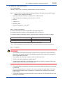
Note 2. Electrical Connection
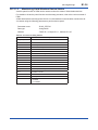
The type of electrical connection is depends on the model code suffix.
The model code suffix is shown on the main label in front of YFGW710.
The second character following the letter A shows the type of electrical connection as below.
Character b on Suffix: Aab-cdefghjkm
The type of electrical connection
2
1/2 NPT female *1
4
M20 female *2
Note *1: 1/2 NPT is realized by the conversion adapter from M20 female to 1/2NPT female.
Note *2: When the cable glands or another device are necessary, user needs to prepare them which adapt to M20 female entry.
IM 01W01F01-01EN
A3-28
<A3. YFGW710 Field Wireless Integrated Gateway>
Note 3. Installation
WARNING
• The installation of the devices should be carried out by the engineers or other professional
personals of the related expertise. The installation should not be carried out by operators or
other unprofessional personals.
• The installation should be in accordance with Canadian Electrical Code Part I or Local Electrical Code.
• YFGW710 should be installed in upright position.
• To satisfy type of protection “n” and degree of protection provided by enclosure IP66, apply
suitable devices to the electrical connection port.
• Make sure that the breakers are installed in the power supply circuits located in non-hazardous areas so that the power can be shutoff when abnormality occurs.
• YFGW710 does not have the Nonincendive Field Wiring. The conduit wiring is required for
the power cable and the metal network cable to be connected to YFGW710.
• When the cable glands are necessary, user needs to prepare the cable glands. The cable
glands shall be certified in type of protection “n” suitable for the conditions of use and correctly installed.
• To maintain the degree of ingress protection IP66 according to IEC 60529, and TYPE4X according to CSA C22.2 No.94 special care must be taken to avoid water.
• Note a warning label worded
“DO NOT OPEN WHEN AN EXPLOSIVE ATMOSPHERE MAY BE PRESENT.”
“POTENTIAL ELECTROSTATIC CHARGING HAZARD – SEE INSTRUCTIONS.”
• Electrostatic charge may cause an explosion hazard. Avoid any actions that cause the generation of electrostatic charge, such as rubbing with a dry cloth on coating face of product.
• Take care not to generate mechanical sparking when access to the instrument and peripheral devices in hazardous locations.
Note 4. Maintenance and Repair
WARNING
• The instrument modification or parts replacement by other than authorized Representative
of Yokogawa Electric Corporation is prohibited and will void the certification.
• When Opening the cover, the enclosure should be dry and clean to prevent from ingress
water or dust.
IM 01W01F01-01EN
<A3. YFGW710 Field Wireless Integrated Gateway>
A3-29
CENELEC ATEX Declaration
(1) Technical Data
Caution for ATEX Type n. (Following contents refer to “Doc No. NKE036”)
Note 1. Model YFGW710 Field Wireless Integrated Gateway with optional code /KN27 is applicable for use in hazardous locations.
• Applicable standard: EN60079-0, EN60079-15, IEC60529:2001
• Type of Protection and Marking Code: Ex nA nL IIC T4 Gc
• Group: II
• Category: 3G
• Enclosure: IP66
• Ambient Temperature: –40 to 60°C
Note 2. Electrical Connection
The type of electrical connection is depends on the model code suffix.
The model code suffix is shown on the main label in front of YFGW710.
The second character following the letter A shows the type of electrical connection as below.
Character b on Suffix: Aab-cdefghjkm
The type of electrical connection
2
1/2 NPT female *1
4
M20 female *2
Note *1: 1/2 NPT is realized by the conversion adapter from M20 female to 1/2NPT female.
Note *2: When the cable glands or another device are necessary, user needs to prepare them which adapt to M20 female entry.
Note 3. Installation
WARNING
• The installation of the devices should be carried out by the engineers or other professional
personals of the related expertise. The installation should not be carried out by operators or
other unprofessional personals.
• The installation should be in accordance with Local Electrical Code.
• YFGW710 should be installed in upright position.
• To satisfy type of protection “n” and degree of protection provided by enclosure IP66, apply
suitable devices to the electrical connection port.
• The conduit wiring is required for the power cable and the metal LAN cable to be connected
to YFGW710.
• When the cable glands are necessary, user needs to prepare the cable glands. The cable
glands shall be certified in type of protection “n” suitable for the conditions of use and correctly installed.
• To maintain the degree of ingress protection IP66 according to IEC 60529 special care must
be taken to avoid water.
IM 01W01F01-01EN
A3-30
<A3. YFGW710 Field Wireless Integrated Gateway>
• YFGW710 does not have a power switch inside. Prepare a dedicated breaker for the external power line to turn ON/OFF the device.
• Make sure that the breakers are installed in the power supply circuits located in non-hazardous areas so that the power can be shutoff when abnormality occurs.
• Note a warning label worded
“DO NOT OPEN WHEN AN EXPLOSIVE ATMOSPHERE MAY BE PRESENT.”
“POTENTIAL ELECTROSTATIC CHARGING HAZARD – SEE INSTRUCTIONS.”
• Electrostatic charge may cause an explosion hazard. Avoid any actions that cause the generation of electrostatic charge, such as rubbing with a dry cloth on coating face of product.
• Take care not to generate mechanical sparking when access to the instrument and peripheral devices in hazardous locations.
(2) Operation
WARNING
• Take care not to generate mechanical sparking when access to the instrument and peripheral devices in hazardous locations.
(3) Maintenance and Repair
WARNING
• The instrument modification or parts replacement by other than authorized Representative
of Yokogawa Electric Corporation is prohibited and will void the EHSRs.
• When Opening the cover, the enclosure should be dry and clean to prevent from ingress
water or dust.
IM 01W01F01-01EN
<A3. YFGW710 Field Wireless Integrated Gateway>
A3-31
(4) Name Plate
• Main name plate
Field Wireless Integrated Gateway
STYLE
MODEL YFGW
SUFFIX
VDC
SUPPLY
NO.
Made in Japan
TOKYO 180-8750 JAPAN
FA0317.ai
MODEL:
Specified model code.
STYLE:
Style code.
SUFFIX:
Specified suffix code.
SUPPLY:
Specified supply voltage and wattage.
NO.:
Serial number and year of production*1.
YOKOGAWA
TOKYO 180-8750 JAPAN:
The manufacturer name and the address*2.
*1:
The third figure from the last of the serial number shows the year of production. For example, the production year of the product
engraved in “NO.” column on the name plate as follows is 2010.
*2:
91K506412 019
The year 2010
“180-8750” is a postal code which represents the following address.
2-9-32 Nakacho, Musashino-shi, Tokyo Japan
• Hazardous class name plate
FA0318.ai
IECEx Certification
(1) Technical Data
Model YFGW710 Field Wireless Integrated Gateway with optional code /SN27 is applicable
for use in hazardous locations.
• Applicable standard: IEC60079-0:2007, IEC60079-15:2005, IEC60529:2001
• Certificate: IECEx KEM 10.0092X
• Type of Protection and Marking Code: Ex nA nL IIC T4 Gc
• Ambient Temperature: –40 to 60°C
• Enclosure: IP66
IM 01W01F01-01EN
A3-32
<A3. YFGW710 Field Wireless Integrated Gateway>
(2) Electrical Connection
The type of electrical connection is depends on the model code suffix.
The model code suffix is shown on the main label in front of YFGW710.
The second character following the letter A shows the type of electrical connection as below.
Character b on Suffix: Aab-cdefghjkm
The type of electrical connection
2
1/2 NPT female *1
4
M20 female *2
Note *1: 1/2 NPT is realized by the conversion adapter from M20 female to 1/2NPT female.
Note *2: When the cable glands or another device are necessary, user needs to prepare them which adapt to M20 female entry.
(3) Installation
WARNING
• The installation of the devices should be carried out by the engineers or other professional
personals of the related expertise. The installation should not be carried out by operators or
other unprofessional personals.
• The installation should be in accordance with Local Electrical Code.
• To satisfy type of protection “n” and degree of protection provided by enclosure IP66, apply
suitable devices to the electrical connection port.
• The conduit wiring is required for the power cable and the metal LAN cable to be connected
to YFGW710.
• The instrument modification or parts replacement by other than authorized representative of
Yokogawa Electric Corporation is prohibited and will void IECEx certificate.
• Provisions shall be made to prevent the rated voltage from being exceeded by transient
disturbances of more than 40%
• When the cable glands are necessary, user needs to prepare the cable glands. The cable
glands shall be certified in type of protection “n” suitable for the conditions of use and correctly installed.
• To maintain the degree of ingress protection IP66 according to IEC 60529 special care must
be taken to avoid water.
• YFGW710 does not have a power switch inside. Prepare an dedicated breaker for the external power line to turn ON/OFF the device.
• Make sure that the breakers are installed in the power supply circuits located in non-hazardous areas so that the power can be shutoff when abnormality occurs.
• Note a warning label worded
“DO NOT OPEN WHEN AN EXPLOSIVE ATMOSPHERE MAY BE PRESENT.”
“POTENTIAL ELECTROSTATIC CHARGING HAZARD – SEE INSTRUCTIONS.”
• Electrostatic charge may cause an explosion hazard. Avoid any actions that cause the generation of electrostatic charge, such as rubbing with a dry cloth on coating face of product.
• Take care not to generate mechanical sparking when access to the instrument and peripheral devices in hazardous locations.
IM 01W01F01-01EN
<A3. YFGW710 Field Wireless Integrated Gateway>
A3-33
(4) Maintenance and Repair
WARNING
The instrument modification or parts replacement by other than authorized Representative of
Yokogawa Electric Corporation is prohibited and will void the certification.
• When Opening the cover, the enclosure should be dry and clean to prevent from ingress
water or dust.
(5) Name Plate
• Main name plate
Field Wireless Integrated Gateway
MODEL YFGW
SUFFIX
SUPPLY
NO.
STYLE
VDC
Made in Japan
TOKYO 180-8750 JAPAN
FA0319.ai
MODEL:
Specified model code.
STYLE:
Style code.
SUFFIX:
Specified suffix code.
SUPPLY:
Specified supply voltage and wattage.
NO.:
Serial number and year of production*1.
YOKOGAWA
TOKYO 180-8750 JAPAN:
The manufacturer name and the address*2.
*1:
The third figure from the last of the serial number shows the year of production. For example, the production year of the product
engraved in “NO.” column on the name plate as follows is 2010.
*2:
91K506412 019
The year 2010
“180-8750” is a postal code which represents the following address.
2-9-32 Nakacho, Musashino-shi, Tokyo Japan
• Hazardous class name plate
FA0320.ai
IM 01W01F01-01EN
<A3. YFGW710 Field Wireless Integrated Gateway>
A3.6.2
A3-34
Model and Suffix Code
Model
Suffix Codes
Descriptions
YFGW710
············································
Field Wireless Integrated Gateway
---
-A·········································
Always A
0······································
1······································
Communication
interface
Electrical connection
0·································
2·································
4·································
-S··························
License
0·······················
1·······················
Manual language
0··················
1··················
Software media
D············
N············
Mounting bracket
A·······
--Option codes
A3.6.3
/
100Base-TX
100Base-TX/100BaseFX
G 1/2 female, two electrical connections
1/2 NPT female, two electrical connections
M20 female, two electrical connections
Single gateway license
Japanese
English
Provided with DVD-ROM
None
2-inch pipe mounting (for vertical piping)
None
Always A
Optional specifications
Optional Specification
Item
Description
Code
X2
Coating
Anti-corrosion coating
External antenna cable
1m
AC1
3m
AC3
4m (1m + 3m) with arrestor
AC13
6m (3m + 3m) with arrestor
AC33
13m (3m + 10m) With arrestor
AC3A
IM 01W01F01-01EN
A3-35
<A3. YFGW710 Field Wireless Integrated Gateway>
Optional Specifications(For Explosion Protected Types)
Item
Description
Code
Factory Mutual
(FM)
FM nonincendive approval
Applicable standard: FM3600, FM3611, FM3810, ANSI/NEMA250
Nonincendive for Class I, Division 2, Groups A, B, C and D;
Class II, Division 2, Groups F and G;
Class III, Division 1 hazardous (Classified) locations.
Enclosure: NEMA 4X
Temp. Class: T4, Amb. Temp.: –40 to 60°C (–40 to 140°F)
FN17
CENELEC
ATEX
CENELEC ATEX Type n declaration
Applicable standard: EN60079-0:2009, EN60079-15:2005,
IEC60529:2001
II 3G Ex nA nL IIC T4 Gc
Enclosure: IP66
Amb. Temp.: –40 to 60°C (–40 to 140°F)
KN27
Canadian Standards
Association
(CSA)
CSA nonincendive approval
Certificate: 2342292
[For CSA C22.2]
Applicable standard: C22.2 No.0, C22.2 No.0.4, C22.2 No.25,
C22.2 No.94, C22.2 No.213, C22.2 No.61010-1-04
Nonincendive for Class I, Division 2, Groups A, B, C and D;
Class II, Division 2, Groups F and G;
Class III, Division 1
Enclosure: Type 4X
[For CSA E60079]
Applicable standard: CAN/CSA E60079-0, CAN/CSA E60079-15,
IEC60529
Ex nA nL IIC T4
Enclosure: IP66
Amb. Temp.: –40 to 60°C (–40 to 140°F)
CN17
IECEx Scheme
IECEx Type n approval
Certificate: IECEx KEM 10.0092X
Applicable standard: IEC60079-0:2007, IEC60079-15:2005,
IEC60529:2001
Ex nA nL IIC T4 Gc
Enclosure: IP66
Amb. Temp.: –40 to 60°C (–40 to 140°F)
SN27
IM 01W01F01-01EN
A3-36
<A3. YFGW710 Field Wireless Integrated Gateway>
A3.6.4
Outline Diagram
YFGW710
Unit: mm (approx. inch)
37.5
(1.48)
2-inch Pipe
Electrical
connection
26
(1.02)
118
(4.65)
Grounding
126.5
(4.98)
100
(3.94)
117 *1
(4.61)
126.5
(4.98)
280
(11.02)
56.5
(2.22)
438
(17.24)
Surface mounting
holes ( 4 - Ø6 )
(7.8)
(0.31)
59
59
(2.32) (2.32)
236
(9.26)
243.8
(9.6)
87.8
(3.46)
36
(1.42) 54.5
(2.15) 111
136.8
(5.39)
(4.37)
190
(7.48)
For Surface Mounting
FA0321.ai
*1: Applicable for electrical connection code 2.
Antenna
■ Antenna
• Omni directional monopole type
• Gain: +2 dBi
■ Remote Antenna
High-frequency Coaxial Cable
• Sheath diameter: 11.1 mm
< Non Arrestor >
< Arrestor Mounting >
Ø20.5 (0.81)
antenna
External antenna
cable (2)
- Select from
Length 10m or 3m
18
(0.71)
150 (5.91)
antenna
arrestor
External antenna
cable
- Select from
Length 3m or 1m
Body
External antenna
cable (1)
- Select from
Length 3m or 1m
Body
FA0322.ai
IM 01W01F01-01EN
<A4. Field Wireless Network>
A4-1
A4. Field Wireless Network
A4.1 Wireless Communication Ranges
The range of wireless communication for each field wireless device and YFGW710 is a toroidal
region having a fan-shaped section spreading 45 degrees vertically above and below from the
center of each device’s antenna and within the range of vision from the antenna.
Horizontal Range
45°
Antenna
45°
Vertical Range
L max
Standard Antenna
FA0401.ai
Fig. B 4-1 Wireless Communication Ranges
Table B 4-1 Wireless Communication Ranges
Location
RF Output (Max.)
Maximum Communication Range (Lmax)
Standard Antenna
Outdoor
10 mW (11.6 dBm)
500 m
Indoor
10 mW (11.6 dBm)
100 m
IMPORTANT
The maximum communication range is the value in the ideal condition, having a good prospect
between wireless devices and existing no obstacle in the wireless transmission route.
The communication distance varies depending on the mounting conditions and environment.
IM 01W01F01-01EN
A4-2
<A4. Field Wireless Network>
A4.2
Wireless System Specification
Specification of Wireless Transmission
Item
Specification
Wireless Standard
ISA100.11a (conforming to IEEE 802.15.4)
Frequency
2400 MHz-2483.5 MHz
Channel
15
Modulation method
Direct sequence spread spectrum (DSSS)
Wireless Output Power
11.6 dBm (Max.), Fixed
Receiving sensitivity
Less than -95 dBm
Communication Range
Radius of 500 m (Max.)
Raw data rate
250 Kbps
Security
AES128 bit encode
*1
*1: Values in the ideal condition. They change (shorten) depending on the conditions.
Number of connected devices
Item
Specification
Maximum Connection
Number
Descriptions
4 clients
―
The total number of host-side
devices connected to the
YFGW710 must not exceed
10.
―
OPC Server
PRM
Field wireless configurator
Field wireless management tool
FieldMate
Note: Refer to the next item for the number of connected field wireless devices.
Number of connected field wireless devices and Publication Period
(Update Time)
When the Update Time of all Field Wireless Device is the same, the maximum connection is
ten devices when Update Time is a second, and the maximum connection is fifty devices when
Update Time is five seconds.
A maximum of two Update Time can be set, and one of them must be longer than 10 seconds
(low speed mode).
Update Time: Group A
Network
Form
Star
Mesh
Update Time: Group B
Update Time A
Number of devices A
Update Time B
Number of devices B
(sec.)
(units)
(sec.)
(units)
1
Max. 5
10 or more
Max. 45
2-4
Max. 10
10 or more
Max. 40
5 or more
Max. 50
10 or more
50 – number of devices A
10 or more
Max. 50
10 or more
50 – number of devices A
IM 01W01F01-01EN
A4-3
<A4. Field Wireless Network>
Network Form (Topology)
This field wireless system supports two network forms – the start network (star topology) and the
mesh network (mesh topology).
We recommend using the star network because of the clear network operations, easy management, and excellent expandability.
Star network
This network form will keep the communication routes which are set at the time of installation.
The delay time is minimized and high reliability is ensured. In order to establish a star network,
YFGW710s must be arranged appropriately so that all field wireless devices can communicate
directly with any YFGW710.
Mesh network
If the data delay time will not cause any specific problem, routing devices can be used for wireless relay. A system with routing devices allows the range of wireless access to be expanded
easily. However, the mesh network has the disadvantages of increased delay time and shortened
battery life of relaying wireless devices.
Network form
Star
Mesh
G
G
Routes
IO
IO
IO
R
R
IO
IO
IO
Hardware components
YFGW710 G
IO device IO
YFGW710 G
Routing device R
IO device IO
Redundant route
Not applicable
Applicable
Number of devices /
YFGW710
Update Time
A maximum of 50 devices/YFGW710
Battery life
Expansion of the range
of wireless access
1 sec. or more
Long
Not route-sensitive
10 sec. or more
Short
Route-sensitive
Add YFGW710s
Add routing devices
FA0402.ai
Note: A network form can be set for each YFGW710.
IM 01W01F01-01EN
<A4. Field Wireless Network>
A4-4
Precautions for a mesh network
Note the following when using a mesh network.
When the number of IO devices (10 units) + routing devices (2 units) exceeds
12
It is difficult to lay out 12 or more Field Wireless Devices for one YFGW710. In this case, please
contact us in advance.
Precautions for arranging wireless transmitters
1.
Two or more routing devices must be arranged on the host side of IO devices. Be sure to
arrange routing devices and the YFGW710 so that all deceives can have two channels.
2.
Up to two hops
Hop 1 is defined as a device that can directly communicate with the Gateway.
Hop 2 is a device that can only establish communication with the Gateway through a routing
device.
We strongly recommend limiting the number of hops to two because of battery life and easy
installation.
Note the above when arranging devices.
G
Hop 1
R
R
IO
IO
Hop 2
FA0403.ai
Service life of the battery of routing devices
The battery life of a routing device depends on the number of IO devices to relay: the more IO
devices, the shorter the battery life.
For details, refer to the standard battery life below.
Setting routing devices
To change “Device Role” of a field wireless device to “Routing Device,” follow the specific procedure using a field wireless configurator.
For details, refer to “Part B: B1.3.2.1 Device Role” in this manual.
IM 01W01F01-01EN
<A4. Field Wireless Network>
A4-5
Standard battery life
The relationship between the Update time of a Field Wireless Device and the battery life in a
standard specification environment is shown below.
The battery life of an IO device is constant irrespective of the network form or the route connection. However, the battery life of a routing device varies greatly according to the route connection.
The larger the number of directly connected devices on the downstream side, the shorter the battery life.
In addition, the battery life varies greatly with temperature; the battery life may be shorter than the
service life shown below.
Update Time (sec.)
Expected battery life when the IO device is set to “Routing Device”
10
x0.1-0.4
30
x0.1-0.5
60
x0.1-0.6
IM 01W01F01-01EN
B1-1
<B1. Engineering>
B1. Engineering
This section describes the engineering to configure a field wireless system compliant with the
industrial automation wireless communication standard ISA100.11a of the International Society
of Automation (ISA).
This section consists of System Engineering Flow Overview, Basics of Engineering, and Applications of Engineering, and the Basics and Applications are guidelines based on the System
Engineering Flow Overview.
A field wireless system consists of the YFGW710 Field Wireless Integrated Gateway (hereinafter referred to as YFGW710) described in Part A, Hardware of this document and field wireless
devices. For details on the field wireless devices, refer to the user's manual of each device.
TIP
Engineering work described in this instruction manual assumes the use of FieldMate R2.03.00 or later.
FieldMate R2.03.00 includes the Provisioning Device Tool.
It also allows parameter settings of field instruments using infrared communications.
IM 01W01F01-01EN
B1-2
<B1. Engineering>
B1.1 System Engineering Flow Overview
(C)
System
Engineer
Control System
Engineering
(CENTUM/STARDOM)
(A)
(B)
Field Wireless
Network Offline
Engineering
(Field Wireless
Configurator)
System
Engineer
System
Engineer
System
Engineer
or Startup
Engineer
Download to YFGW710
(Field Wireless
Configurator)
Person in Charge of Devices
Setting and adjusting
device parameters
(FieldMate *1)
Person in Charge of Devices
Device Installation
Person in Charge of Devices
Check Wireless
Network
Operation Conditions
(Field Wireless
Management Tool)
Set and Adjust
Device Parameters
(PRM)
System
Engineer
or Startup
Engineer
Provisioning
(FieldMate)
Downloading of Process
Data Communication
Definitions
(Field Wireless
Configurator)
Person
in Charge
of Devices
If necessary
Loop Check
User or
Startup Engineer
Person in Charge of Devices
Operation/Monitoring
Device Management
Operators
Maintenance
Staff
FB0101.ai
Figure B1-1 System Engineering Flow Overview
Figure B1-1 shows the system engineering flow overview of the field wireless system. This system engineering is roughly classified into three tasks.
• (A) Setting and adjustment of field wireless devices by the person in charge of the devices
before the installation of them
• (B) Construction of a field wireless network by the system engineer (or the startup engineer)
• (C) Engineering of the control system by the system engineer
*1 Applicable for FieldMate R2.03.00 or later. This concerns Yokogawa field devices.
(Use PRM to set and adjust parameters of field devices of other manufacturers.)
IM 01W01F01-01EN
B1-3
<B1. Engineering>
n Setting and adjustment of field wireless devices before the installation
of them by the person in charge of the devices
This task refers to the setting and adjusting the required information in field wireless devices performed by the person in charge of devices before they are installed in the field.
As shown in Figure B1-1, tasks that need to be performed before a field wireless device can be
installed in the field include the following.
• Provisioning
Provisioning is the loading of the required information in a device to integrate it with the field
wireless network. This task must be performed before a device can be installed in the field.
• Setting and adjusting device parameters
A Yokogawa field wireless device allows the person in charge of field devices to set and
adjust device parameters before a device is installed in the field. This task can also be
performed after the device has been installed in the field. Use FieldMate R2.03.00 to perform this task before installing a device in the field. For details, refer to “ISA100.11a wireless
devices” in Part I of the instruction manual (IM 01R01A01-01E) supplied with FieldMate.
Provisioning is a task to set the information necessary for the field wireless devices to join the
field wireless network. This task is necessary to prevent a third party from gaining unauthorized
access to the wireless network as an imposter and tampering with data. Devices that are not
provisioned or devices for which incorrect information is set cannot join the wireless network.
For the procedure, refer to B1.2 and the following sections.
n Construction of a field wireless network by the system engineer
This task is the construction of a field wireless network using Field Wireless Configurator by the
system engineer (including the startup engineer).
The wireless network construction task includes the following tasks: field wireless network offline
engineering, downloading to YFGW710, checking the field wireless network operation conditions, setting and adjusting the field wireless device parameters, and downloading the process
data communication definitions. For the procedure, refer to B1.2 and the following sections.
The tasks of downloading to YFGW710, checking the field wireless network operation conditions,
and downloading the process data communication definitions are supposed to be performed by
the system engineer (or the startup engineer) after the devices are delivered to the plant site of
the customer. For details, refer to section B1.2.
The task of setting and adjusting the device parameters is supposed to be performed by the
person in charge of the devices.
n Engineering of the control system by the system engineer
This task is the engineering of the host (control/monitoring) system by the system engineer.
For details, refer to the user's manual of each host system.
IM 01W01F01-01EN
B1-4
<B1. Engineering>
B1.2 Basics
This section describes the procedure to construct a network by connecting one YFGW710 and
one field wireless device.
n System Example
HUB
-IP Address 192.168.0.101
-Subnet mask 255.255.255.0
-Default Gateway 192.168.0.1
-IP Address 192.168.0.102
-Subnet mask 255.255.255.0
-Default Gateway 192.168.0.1
PC2
PC1
Gateway
-FieldMate with
Provisioning funciton
-Field Wireless Configurator
-Field Wireless Management Tool
PV
Field Wireless Device
-Device Tag = DEV_001
-Device Role = IO only
Field Wireless network
-Network ID: 100
FB0102.ai
Figure B1-2 Field Wireless Network System Example
To facilitate the understanding of the basic construction procedure of a field wireless network,
the following describes the procedure to construct a system configured as shown in Figure B1-2,
which transmits process data (PV values) measured by the field wireless device to YFGW710 at
a period of 10 seconds.
The field wireless device has a function to receive and transfer communication frames of other
field wireless devices (Routing function) and a function to send process data measured by itself
(IO function).
A field wireless device that has both functions is called a Router + IO device, and a device that
has only the IO function is called an IO device. A device that has only a Routing function is called
a Routing device.
In this system, a field wireless device is used as the IO device.
PC1 in Figure B1-2 has Field Wireless Configurator for setting and maintaining the field wireless
network and Field Wireless Management Tool for managing the field wireless network and field
wireless device as well as checking the operation conditions installed.
PC2 has FieldMate that performs provisioning of the field wireless device and FieldMate Provisioning Device Tool that works in conjunction with FieldMate installed. The setting of the field
wireless device to allow it to join the field wireless network is performed from the PCs via an
infrared adapter.
Note: FieldMate R2.03.00 or later allows you to use infrared communications to set device information.
For details, refer to “I-7 Obtaining ISA100 device information” in the instruction manual (IM 01R01A01-01E) supplied with FieldMate.
IM 01W01F01-01EN
B1-5
<B1. Engineering>
B1.2.1
Preparations
n Network Design
To construct a field wireless network, the following items must be determined beforehand.
Namely, a network ID, a device tag of the field wireless device to use, and network information for
connecting YFGW710 by Ethernet.
This information is necessary for the system engineer and the person in charge of the devices to
perform their tasks, and this information must be shared by both to efficiently construct the field
wireless network.
Network ID
Determine the network ID (2 to 65535) of the field wireless network comprising YFGW710 and a
field wireless device. The network ID in the example of Figure B1-2 is 100.
Selecting the field wireless device to use and check the device information
Check the vendor ID, model ID, and device revision of the field wireless device to use.
Device tag
A name assigned to the field wireless device for identifying the device. Set a name that is unique
on the wireless network in the same field. The device tag in the example of Figure B1-2 is DEV_
001.
Network parameters for Ethernet connection
Network parameters necessary to connect YFGW710 and the PCs to Ethernet. Namely, IP address, subnet mask, and default gateway. Do not use identical IP addresses on the same Ethernet.
Set the network parameters of YFGW710 and the PC1 in the example of Figure B1-2 as follows.
Table B1-1 Network Parameter Setting Example
Item
YFGW710
IP Address
192.168.0.101
Subnet Mask
255.255.255.0
Default Gateway
192.168.0.1
PC1
192.168.0.102
IM 01W01F01-01EN
<B1. Engineering>
B1-6
n Hardware Preparation
l YFGW710
l Field wireless device
l Two PCs
Provide two PCs, namely, one to install Field Wireless Configurator and Field Wireless Management Tool, and one to install Field Mate.
An Ethernet interface (100BASE-TX) is required for PC1 that is connected by Ethernet.
l HUB
n Preparation for Software
Installing software
Before constructing a field wireless network, provide the following software and install them on
the PCs to be used.
• PC1
Field Wireless Configurator R1.02.00 or later
Field Wireless Management Tool R1.02.00 or later
This software is included on the DVD-ROM that is supplied with YFGW710. For the installation procedure, refer to Part C, “Wireless System Setting and Management Software” of this
document.
Microsoft .Net Framework 3.5 Service Pack 1 is required for Field Wireless Configurator and
Field Wireless Management Tool.
If Microsoft .NET Framework 3.5 Service Pack 1 is not installed on PC1, it will be installed
when the Field Wireless Configurator and Field Wireless Management Tool are installed.
For details, refer to “C2.2.2 Installation Procedure” or “C3.2.2 Installation Procedure” in Part
C.
If an old version of the Field Wireless Configurator or Field Wireless Management Tool is
installed on PC1, install this software to update it. For details, refer to “C.2.2.2 Installation
Procedure” and “C3.2.2 Installation Procedure” in Part C.
If you are using the Windows Server 2008 R2 operating system, Microsoft .NET Framework
3.5 Service Pack 1 is preinstalled but must also be enabled. For details on how to check
whether Service Pack 1 is enabled and how to enable it, refer to “TIP” in “C1. System Requirements of Provided Software.”
IM 01W01F01-01EN
B1-7
<B1. Engineering>
• PC2
FieldMate R2.03.00 or later
To set and adjust device parameters in field wireless devices before installation, install FieldMate R2.03.00 or later.
First, install FieldMate according to the instructions in the following user's manual.
IM01R01A04-01 FieldMate Device Adjustment and Setting Software
Simple Start Manual
IM01R01A04-01 FieldMate Device Adjustment and Setting Software
Preparation for Capabilities File and Device DTM
Obtain Capabilities File and Device DTM of the field wireless device that is connected to the wireless network. Capabilities File and Device DTM are provided by the field wireless device vender.
Ask the field wireless device vendor how to obtain them. For Yokogawa field devices, visit the
following web site to download the necessary files.
< http://www.field-wireless.com/ >
When using PRM or FieldMate, visit and check the following web site for the applicable setting
tool and DeviceFiles revision.
< http://www.field-wireless.com/ >
- For PRM R3.05 or later, use the DeviceFiles included in the package or download the
appropriate DeviceFiles from the PRM user’s site.
- For FieldMate R2.03 or later, use the DeviceFiles included in the package or download the
appropriate DeviceFiles from the FieldMate user’s site.
- Use PRM R3.10 or later and FieldMate R2.04 or later for YTMX580 multi-input temperature
transmitter.
B1.2.2
Field Wireless Network Offline Engineering
The task of the field wireless network offline engineering is performed using Field Wireless Configurator in the following steps.
• Creating a Project Database
• Registering YFGW710
• Registering a Field Wireless Device
• Loading a Capabilities File (CF)
• User Application Engineering
B1.2.2.1
Creating a Project Database
Create a project database using Field Wireless Configurator. For details on the procedure, refer
to C2, “Field Wireless Configurator” in Part C of this document.
IM 01W01F01-01EN
B1-8
<B1. Engineering>
n Project Database Storage Folder and Folder Name
By default, project data is saved to the folder displayed in Default Folder for Project Files in the
Options window of Field Wireless Configurator.
To open the [Options] window, click on [Tools] – [Options] in the menu in the Main window.
FB0103.ai
Figure B1-3 Project Database Folder
The file name is as follows.
<Any project name>.yep
Up to 16 single-byte alphanumeric characters, hyphens, and underscores can be used for the
project name.
n Backing Up Project Database
When the task of constructing the field wireless network is completed, back up the project database.
TIP
Use the backup function to save the project. For details, refer to C2.3.3.1 Project Actions” in Part C. Do not
change the project file name from Explorer or the like. For a project whose project file name was changed, operation is not guaranteed with Field Wireless Configurator.
IM 01W01F01-01EN
B1.2.2.2
<B1. Engineering>
B1-9
Registering YFGW710
Register YFGW7010 with the project database. For details on the registration procedure, refer to
C2, “Field Wireless Configurator” in Part C of this document.
After the registration, set the following YFGW710 parameters displayed on the page of the Network Information tab in the right pane of the Main window of Field Wireless Configurator.
n Network Information Field
Table B1-2 Network Information Setting
Parameter name
Network ID
TIP
Setting value
Remark
Enter the appropriate network ID (2 to 65535).
Specify 100 for the field wireless network in
Figure B1-2.
YFGW710 runs with the network ID specified here.
When the network ID is changed, provisioning of the field wireless device must be performed again.
n IPv4 Settings Field
Table B1-3 Configuring IPv4 Settings
Parameter name
IP Address
Subnet Mask
Default Gateway
NTP Server IP Address
Setting value
Remark
Set the values assigned to YFGW710 by the
wireless network engineering.
Specify the following for the field wireless
network in Figure B1-2.
IP Address: 192.168.0.101
Subnet mask : 255.255.255.0
Default Gateway: 192.168.0.1
Field Wireless Configurator accesses
YFGW710 specified here.
Specify the IP address of the NTP server.
When an NTP server is not used, set the
same IP address as the default gateway.
IM 01W01F01-01EN
<B1. Engineering>
B1-10
n Gateway Field
Table B1-4 Setting Gateway
Parameter name
Device Tag
Setting value
Specify the device tag of the gateway.
Remark
By default, the device tag is YFGWGWnnn.
nnn is from 001 to 999, any of which is
automatically assigned so that the device
tag is unique in the project.
n System Manager/Security Manager Field
Table B1-5 Setting System Manager/Security Manager
Parameter name
Setting value
Remark
Device Tag
Specify the device tag of System Manager.
By default, the device tag is YFGWSMnnn.
nnn is from 001 to 999, any of which is
automatically assigned so that the device
tag is unique in the project.
EUI-64
EUI-64 of System Manager
Display only
Channels
Check the channels to use. By default, all 15
channels are checked.
Clear the check mark for channels that are
prohibited by the radio law of the country or
region where YFGW710 is used.
Channels 0 to 14 are displayed in Field
Wireless Configurator. These channels
correspond to channels 11 to 25 defined in
IEEE 802.15.4.
Topology
Specify the network topology.
The following two types can be selected.
• Star (default)
• Mesh
For details on changing the network topology, refer to section B1.2.2.5.
Max Nodes
50 nodes is specified by default.
Do not change it.
Max Latency
0% is specified by default.
Do not change it.
Max Device Timeout
120 seconds is specified by default.
Do not change it.
Advertise Period
7 seconds is specified by default.
Do not change it.
Join Links Period
4 seconds is specified by default.
Do not change it.
PER
15% is specified by default.
When the network is a mesh topology, this
is the standard for switching paths.
TIP
There is the case that notation of “EUI64” is used for device unique 64bits address (EUI-64) of both the field wireless devices and each function of YFGW710 in display of software that is referenced “PART C C2. Field Wireless
Configurator” by this chapter.
IM 01W01F01-01EN
<B1. Engineering>
B1-11
n Channels (System Manager/Security Manager Field)
An ISA100.11a field wireless network uses the wireless frequency band corresponding to each
channel defined in IEEE 802.15.4. When there is a band whose use is prohibited by the law of
the country or region where the wireless network is used, clear the check mark in front of the corresponding channel.
Table B1-6 RF Channel
ISA100.11a
IEEE802.15.4
Band (MHz)
ISA100.11a
IEEE802.15.4
Band (MHz)
0
11
2405
8
19
2445
1
12
2410
9
20
2450
2
13
2415
10
21
2455
3
14
2420
11
22
2460
4
15
2425
12
23
2465
5
16
2430
13
24
2470
6
17
2435
14
25
2475
7
18
2440
15 (use is always
prohibited)
26
2480
n Backbone Router Field
Table B1-7 Setting Backbone Router
Parameter name
Setting value
Remark
Device Tag
Specify the device tag of the backbone router.
By default, the device tag is YFGWBBRnnn.
nnn is from 001 to 999, any of which is
automatically assigned so that the device
tag is unique in the project.
Filter Bit Mask
0xFFFF is specified by default.
Do not change it.
Filter Target ID
(Subnet ID)
NetworkID = Subnet ID for YFGW710 that is
used in this system.
Display only
TIP
Filter Bit Mask and Filter Target ID
These parameters are used when constructing multiple logically independent field wireless networks on a single
field wireless network.
However, with respect to a system consisting of currently available wireless devices, a single logical field wireless
network is constructed on a single field wireless network like in the example of this system. Do not change the
filter bit mask and filter target ID but use the default values.
TIP
YFGW710 Field Wireless Integrated Gateway consists of functions that are Gateway, System Manager/Security
Manager and Backbone Router.
IM 01W01F01-01EN
B1.2.2.3
<B1. Engineering>
B1-12
Registering Field Wireless Device
Register the field wireless device to allow it to join the wireless network. For details on the registration procedure, refer to C2, “Field Wireless Configurator” in Part C of this document.
After registering the field wireless device, set the following related parameters.
Table B1-8 Setting Field Wireless Device Parameters
Parameter name
Setting value
Remark
Device Tag
Enter the device tag set to the field wireless
device by provisioning in section B1.2.3.2.
Up to 16 single-byte capital alphabet letters,
numbers, hyphens, and underscores can be
used.
When an incorrect device tag is set, “Registering a Provisioning Information File with
the Project Database” and “Downloading
to the Field Wireless Device” described
later cannot be executed correctly.
EUI-64
EUI-64 of the target field wireless device
Join Key
Join key of the target field wireless device
Automatically registered during the task
of “B1.2.4.1 Registering a Provisioning
Information with the Project Database”
described later.
Device Role
Device role of the field wireless device
For details, refer to section B1.2.2.5.
Provisioner Name
Name of user who provisioned the target field
wireless device
Provisioning Time
Time at which the target field wireless device
was provisioned. It is displayed in UTC.
Automatically registered during the task
of “B1.2.4.1 Registering a Provisioning
Information with the Project Database”
described later.
B1.2.2.4
Loading a Capabilities File (CF)
Before performing User Application Engineering in section B1.2.3.5, it is necessary to obtain a
Capabilities File (CF) of the target field wireless device and load CF during the task of registering
the field wireless device using Field Wireless Configurator.
Copy CF to the specified folder and load it using Field Wireless Configurator. For details on the
procedure, refer to C2, “Field Wireless Configurator” in Part C of this document. For the copy
destination, refer to section “■ CF Copy Destination Folder” described later.
n CF
CF contains information on the vendor name, model name, and revision of the field wireless
device, and built-in process data (measurement values such as flow rate, temperature, and pressure). CF is provided by the device vendor.
TIP
Do not change the content of CF with a text editor or the like. If it is changed, “User Application Engineering” in
section B1.2.2.5 cannot be performed correctly.
IM 01W01F01-01EN
<B1. Engineering>
B1-13
n CF File Naming Rule
The CF file name is determined by the following rule.
<Vendor ID>\<Model ID>\<Device Revision><DD Revision><CF Revision>.cff
Yokogawa vender ID: 00594543
EJX model ID: 000C
YTA model ID: 0005
n CF Copy Destination Folder
Obtain CF from the device vendor and copy it to the following folder.
The folder is shown at [Default Folder for CF/DD Files] of [File Options] in the Option window.
To open the [Options] window, click [Tools] – [Options] in the Main window.
Default setting is
“C: \Yokogawa\FieldWireless\FieldWirelessConfigurator\CFDD”.
For details, refer to C2, Field Wireless Configurator in Part C of this document.
FB0104.ai
Figure B1-4 CF Copy Destination Folder
IM 01W01F01-01EN
<B1. Engineering>
B1.2.2.5
B1-14
User Application Engineering
User Application Engineering consists of the following three tasks.
• Defining device role
• Defining process data communication (setting which data of the field wireless device is notified to which device (YFGW710) and at which period)
• Defining Modbus Register map
Loading CF using Field Wireless Configurator displays the attribute information on the field wireless device and enables working on the above three definitions.
n Defining Device Role
A device role refers to the functional role of the field wireless device (IO and routing functions).
Field Wireless Configurator displays all the device roles supported by the target field wireless device. Select the appropriate one from the IO and routing functions according to your needs. You
can select more than one role. In window setting Device Role, the IO function is shown as “IO”,
and the routing function is shown as “Router”.
A field wireless device that joins the field wireless network works with the selected function.
Field Wireless Management Tool allows you to confirm the function with which the field wireless
device works.
Changing the device role of an operating field wireless device causes it to restart when settings
are downloaded. For details, refer to section B1.3.2.1 of this document.
Notes when the network is star topology
When the network is selected as the star topology in section B1.2.2.2, only the field wireless device for which the IO function (alone or IO + routing function) is selected for the device role joins
the field wireless network. Only the IO function of all the joining field devices is enabled.
A field wireless device for which the IO function is not selected (only the routing function is selected) is not able to join the field wireless network.
Notes when the network is mesh topology
When the network is selected as the mesh topology in section B1.2.2.2, the maximum number of
field wireless devices you can set the routing function for the device role is 10.
When setting the routing function for 11 or more field wireless devices, communication with an
unspecified number of field wireless devices connected to the field wireless network in question
may not be performed normally. Such a condition may cause process alarms such as IOP or
a system alarm indicating the field wireless device is no longer joined with Yokogawa's control
system.
IM 01W01F01-01EN
<B1. Engineering>
B1-15
n Defining Process Data Communication
Define the transfer period and transfer destination (YFGW710 for this system) for each piece of
data of the field wireless device.
Table B1-9 Setting Parameters for Defining Process Data Communication
Parameter name
Setting value
Remark
Sampling Parameters
Specify the field wireless device data to notify
to YFGW710.
By default, the process data of the field wireless device is specified.
The following three types can be set to
Sampling Parameters.
Unless all parameters are set, the field
wireless device will not transmit any data.
PV
PV_B
DAIG_STATUS
Update Policy
Change is not necessary.
Periodic and Change of State can be set.
Always specify Periodic.
Change of State is a method to notify only
when data is changed.
Periodic is a method to notify of data at a
period specified in Publication Period.
Always specify Periodic for this system.
Publication Period
Change the period if necessary.
The range is from 1 to 60 seconds.
5 seconds by default.
When 0 second is specified, no data is
notified from the field wireless device.
Stale Limit Time
Change the time if necessary.
The range is from 10 to 255 seconds.
50 seconds by default.
Set a value that is larger than the publication
period.
When this specified time is exceeded and
data cannot be received from the field
wireless device, YFGW710 considers that
a communication error has occurred.
Destination for data
The device tag of the communication destination is set.
Always point to YFGW710.
Change is not necessary.
Publication Period and Stale Limit Time
• Publication Period
A publication period refers to a period at which the process data is notified to YFGW710
from the field wireless device.
Determine the publication period considering battery power consumption (which varies
depending on the publication period) or other factors.
• Stale Limit Time
The check process of wireless communication, the operating environment of the system,
deterioration of wireless quality, and communication path error and restoration may cause
data loss, retransmission of the same data, or variations in the data update time.
When the state of not-updated-data or lost-data continues for the period specified in Stale
Limit Time, YFGW710 considers that an error has occurred and notifies the control system
of an error.
Be sure to set a value that is larger than the publication period. It is recommended to set a value
10 times as large as the publication period. However, determine the value considering the fact
that the time from when the state of data-not-updated or data-lost occurs until the determination
of an error varies depending on the system environment and user application.
IM 01W01F01-01EN
B1-16
<B1. Engineering>
n Defining Modbus Register Map
When communicating with the control system using Modbus communication, this task needs to
be performed.
For details on the procedure to assign to the Modbus Register map, refer to C2, “Field Wireless
Configurator” in Part C of this document.
Only assignment to Input Register is possible for this system. Assignment to Holding Register is
not possible.
TIP
It is only possible to assign the PV value of the device and DIAG_STATUS indicating the diagnostic result of the
device to Input Register.
B1.2.3
Work before Installing Field Wireless Device
This section describes the following tasks that need to be performed for the device and
YFGW710 before the field wireless devices are installed in the field at the plant.
• Task of Setting YFGW710
• Task of Provisioning a Field Wireless Device
• Setting and adjusting field wireless device parameters (this can be performed after installation)
B1.2.3.1
Task of Setting YFGW710
Before installing YFGW710, the task of setting YFGW710 for connecting by Ethernet is necessary. By factory default, the following values are set to YFGW710.
Table B1-10 YFGW710 Network Parameter Factory Default Values
Item
Default value
IP Address
192.168.0.101
Subnet Mask
255.255.255.0
Default Gateway
192.168.0.1
When changing the YFGW710 network parameter, connect the PC on which Field Wireless Configurator is installed and YFGW710, and follow the instructions described below.
Ensure the IP address of the PC is an IP address other than the factory default IP address of
YFGW710 (namely, an IP address other than 192.168.0.101).
IM 01W01F01-01EN
<B1. Engineering>
B1-17
n Procedure to Set YFGW710 Network Parameters
TIP
1.
Connect the PC on which Field Wireless Configurator is installed to YFGW710 for which to
set the network parameters on a peer-to-peer basis.
2.
To check the routing of the PC and YFGW710, access the current YFGW710
(192.168.0.101 by factory default) from the PC using the ping command. If the ping command does not work normally, a routing error occurs or there is a problem with the network
settings of the PC. Check the routing and the network settings of the PC.
3.
Create a project using Field Wireless Configurator. This project is only used to change the
YFGW710 network parameters.
4.
Set the values to change for IP Address, Subnet Mask, and Default Gateway in the [IPv4
Settings] field on the page of the [Network Information] tab in the Main window of Field Wireless Configurator. The other values do not need not to be changed. For the actual procedure, refer to C2 of Part C of this document.
5.
To set new YFGW710 network parameters, click on [Tools] – [Download] in the menu in the
Main window of Field Wireless Configurator to open the [Download Project Data] window.
6.
Set the IP address before the change (192.168.0.101 for this example) for IP Address in the
[Connection Information] field in the [Download Project Data] window and click the [Start
download] button. After the download starts, YFGW710 will automatically restart during the
download. It will take a maximum of 2 minutes for YFGW710 to automatically restart and
then enter the running normally state.
7.
When YFGW710 restarts, check that the new YFGW710 network parameters are set to
the target YFGW710 using the ping command from the PC. If the ping command response
is not normal, there is a problem with the network settings of the PC. In particular, when
the IP address was changed to a different segment (for example, when the IP address of
YFGW710 was changed from 192.168.0.101 to 10.0.1.1), the network settings of the PC
need to be set again so that access to the new segment becomes possible.
Ensure that the IP addresses of all the machines (YFGW710 and PCs) connected by Ethernet are unique.
IM 01W01F01-01EN
<B1. Engineering>
B1.2.3.2
B1-18
Task of Provisioning a Field Wireless Device
The task of provisioning a field wireless device is performed using a PC on which FieldMate and
FieldMate Provisioning Device Tool are installed. The setting is performed for each field wireless
device using an infrared adapter.
n Provisioning Task Work Flow
The provisioning task must be performed to allow a field wireless device to join the field wireless
network.
Figure B1-5 shows the provisioning work flow overview.
System Engineer
-Network ID = 100
-Device Tag = DEV_001
S1. Input
Field Wireless Configurator
Project
Database
S2. Load
Provisioning Information file
Network ID = 100
Device
= FIC100
Network
IDTag
= 100
JoinTag
Key==DEV_001
“$D&#Y”
Device
= zzzz:zzzz:zzzz:zzzz
JoinEUI_64
Key = “11223344
...”
EUI-64 = yyyy:yyyy:yyyy:yyyy
Person in charge of devices
-Network ID = 100
-Device Tag = DEV_001
M1. Input
S3. Download to Gateway
Gateway
Join
-EUI-64 = yyyy:yyyy:yyyy:yyyy
-Device Tag = DEV_001
and so on
-Device Tag = DEV_001
-Join Key = “11223344...”
-EUI-64 = yyyy:yyyy:yyyy:yyyy
Device Installation
M2. Save
M1. Setting
FieldMate
(Provisioning Device)
-Network ID = 100
-Join Key = “11223344...”
-Device Tag = DEV_001
and so on
Device
(EUI-64 : yyyy:yyyy:yyyy:yyyy)
FB0105.ai
Figure B1-5 Provisioning Work Flow Overview
The person in charge of the devices performs the provisioning task (Figure B1-5, M1) and the
provisioning information file creation task (Figure B1-5, M2).
The system engineer creates a project database using Field Wireless Configurator. (Figure B1-5,
S1. For details, refer to section B1.2.2.)
Next, the provisioning information file created by the person in charge of the devices is registered
with the project database. (Figure B1-5, S2. For details, refer to section B1.2.4. and the following
sections.)
After the registration, the project data is downloaded to YFGW710. (Figure B1-5, S3. For details,
refer to section B1.2.4.)
When the above tasks are completed, the field wireless device is able to join the field wireless
network and communicate with YFGW710.
To add a new field wireless device or replace one, the same procedure must be performed.
IM 01W01F01-01EN
<B1. Engineering>
B1-19
n Setting Provisioning Information
The setting of the device tag and network ID is performed using a provisioning function in FieldMate.
The device tag, network ID, and join key are set to the field wireless device. However, the join key
does not need to be entered because it is automatically generated by FieldMate.
Setting Device Tag
A device tag is used for the user to identify the field wireless device.
Set “DEV_001” for the example of Figure B1-2.
Setting Network ID
A network ID is used for the field wireless device to join the field wireless network.
Set a decimal value from 2 to 65535.
A field wireless device is able to join the field wireless network that matches the network ID set by
the provisioning task.
Set “100” for the example of Figure B1-2.
n Creating a Provisioning Information File
A provisioning information file includes the following information that was set to the field wireless
device by provisioning.
• Network ID
• Device Tag
• EUI-64
• Join Key
• Provisioner (Name of user who performed provisioning operation)
• Date (time of day at which provisioning was performed)
Keep this provisioning information file, which will be used to write data from Field Wireless Configurator (described later) to YFGW710.
Storing a Provisioning Information File
If a provisioning information file is lost, the same file as the lost provisioning information file cannot be restored. The provisioning task must be performed again to create the file.
Keep provisioning information file carefully so as not to lose it.
Creating Multiple Provisioning Information Files
Provisioning information on multiple field wireless devices can be recorded in a single provisioning information file. Furthermore, provisioning information files can be created for multiple devices.
IM 01W01F01-01EN
B1-20
<B1. Engineering>
B1.2.3.3 Adjusting and Setting Field Wireless Device Parameters
Use FieldMate to adjust and set parameters before installing a field wireless device.
For details, refer to “ISA100.11a wireless devices” in Part I of the instruction manual (IM
01R01A01-01E) supplied with FieldMate.
Use FieldMate R2.03.00 or later to do this work.
Note that this work need not be done before installing a device in the field. Use PRM via
YFGW710 to adjust and set parameters of field wireless devices after installation. For details,
refer to Chapter B1.2.6.
B1.2.4
Downloading to YFGW710
Download to YFGW710 the project database information created by the field wireless network
offline engineering described in section B1.2.2.
The tasks in B1.2.4 and the following subjections are supposed to be performed by the system
engineer (or the startup engineer) after the wireless devices are delivered to the plant site of the
customer.
When downloading to YFGW710 is completed, the field wireless device whose provisioning task
is completed is able to join the field wireless network.
The following tasks need to be performed.
• Registering Provisioning Information with the Project Database
• Downloading to YFGW710
B1.2.4.1
Registering Provisioning Information with the Project
Database
This is a task to obtain the provisioning information from the provisioning information file created
in the procedure in section B1.2.3.2 and register it with the project database of Field Wireless
Configurator.
For details on the procedure to register the provisioning information, refer to C2, “Field Wireless
Configurator” in Part C of this document.
Note that this task must be performed before downloading to YFGW710.
The provisioning information (EUI-64 and Join Key) is shared by the field wireless device and
YFGW710.
The provisioning information is shared by the field wireless device and YFGW710 by obtaining
the provisioning information from the provisioning information file, registering it with the project
database, and then writing it to YFGW710.
Registration Information
The following information of the provisioning information file data is registered with the project
database.
• EUI-64
• Join Key
• Provisioner: Name of user who performed provisioning using FieldMate
• Date: Time of day at which provisioning was performed using FieldMate
TIP
The above information that was registered cannot be changed from Field Wireless Configurator.
IM 01W01F01-01EN
B1-21
<B1. Engineering>
Registration Conditions
The provisioning information of the field wireless device that matches the target network ID in the
provisioning information file is registered with the project database.
When a device tag is already registered with the project database, the information described in
the registration information is registered and updates the existing information. When a device tag
is not registered with the project database, the information described in the registration information and the device tag are newly registered with the project database.
TIP
The task of registering the provisioning information from the provisioning information file with the project database
performs association using the device tag. When the device tag in the provisioning information file and the device
tag in the project database are not identical, this registration task does not replace the device tag in the project
database with the device tag in the provisioning information file.
In such a case, change the device tag in the project database and perform the registration task again.
Confirmation Dialog Box
When registering the provisioning information using Field Wireless Configurator, the Device Provisioning window (confirmation dialog box) appears.
Figure B1-6 Confirmation Diaglog Box
IM 01W01F01-01EN
<B1. Engineering>
B1-22
The confirmation dialog box appears when you perform the following procedure: open the page
of the Devices tab while the network information is being displayed in the right pane in the Main
window of Field Wireless Configurator, click the Load Devices List button in the toolbar, and then
select and open the provisioning information file to read.
The following explanation uses “DEV_001”, “DEV_002”, and “DEV_003 *” in Figure B1-6 as an
example.
In the [Newer Devices] field on the right of the confirmation dialog box, device tags are displayed,
whose provisioning information in the provisioning information file is to be registered with the
project database.
A device tag marked with an asterisk “*” (e.g. DEV_003*) indicates that the device tag exists in
the provisioning information file, but the device tag in question does not exist in the project database.
In such a case, clicking the [OK] button, while the check box on the left of the device tag is
checked, registers the device tag and the provisioning information with the project database.
A device tag without an asterisk “*” (e.g. DEV_001) indicates that the device tag in question exists
in the provisioning information file and the project database, and clicking the [OK] button, while
the check box on the left of the device tag is checked, updates the provisioning information in the
project database.
The [Older Devices] field on the left of the Confirmation Dialog window indicates that the device
tag in question exists in the provisioning information file and the project database (e.g. DEV_
002).
A device displayed in the [Older Devices] field indicates that the same provisioning information
is already registered with the project database, or older provisioning information is about to be
registered. Even clicking the [OK] button, while the device tag check box is not checked, does not
update the provisioning information in the project database. Clicking the [OK] button, while the
device tag check box is checked, updates the provisioning information in the project database.
The lower pane may show the device tag name and the message “Different Device Tag” (example: DEV_004). In this case, no provisioning information for the device tag has been imported.
This means that the device tag in the project database differs from the device tag in the provisioning information file although they have the same EUI-64 address. For example, this message
appears when a device tag is changed by reprovisioning without changing the device tag for the
device in the project database. If this happens, either change the device tag for the device in the
project database or correct provisioning in the device so that the device tag in the project database for the device matches the device tag in provisioning information file.
IM 01W01F01-01EN
<B1. Engineering>
B1-23
How to Specify Provisioning Information Files
Multiple provisioning information files can be registered with the project database at the same
time. Copy all the provisioning information files to a particular folder and specify all the files.
If there is a provisioning information file that is not specified, specify that provisioning information
file and register it again. At this point, there is no problem specifying provisioning information files
that is already registered at the same time. The information in the provisioning information file
that is already registered is displayed in [Older Devices] in the confirmation dialog box.
If the provisioning information on the same device coexists in the specified multiple provisioning
information files, the latest information is automatically selected and the device tag of the selected device is displayed in the confirmation dialog box in Figure B1-6.
For example, when provisioning of the same device is performed from different provisioning devices, multiple provisioning information files are created. When all these provisioning information
files are specified, Field Wireless Configurator selects the latest information from the specified
provisioning information files and displays it in the confirmation dialog box.
IMPORTANT
[Note on the time of day of a PC on which the provisioning device runs]
On the PC that operates FieldMate Provisioning Device Tool, when the provisioning device performs provisioning of the field wireless device, it also saves the time of day (UTC) in the provisioning information file. Field Wireless Configurator selects the latest information based on that
time of day. Accordingly, set the time of day of a PC, on which the provisioning device runs, to the
local time in a region where the PC is used and that is set on the PC.
Keeping Provisioning Information File after Registration
After registering the provisioning information from the provisioning information file with the project
database, keep the provisioning information file carefully.
IMPORTANT
[Provisioning information registration error]
When a single provisioning information file includes information on a field wireless device that
has duplicate EUI-64, the provisioning information cannot be obtained (there is no change to the
project database).
When multiple provisioning information files are specified and even one of them includes duplicate EUI-64, the provisioning information cannot be obtained (there is no change to the project
database).
FieldMate Provisioning Device Tool is not able to create information on a field wireless device
that includes duplicate EUI-64 in a single provisioning information file.
IM 01W01F01-01EN
B1.2.4.2
<B1. Engineering>
B1-24
Downloading to YFGW710
To write the provisioning information to YFGW710, click on [Tools] – [Download] in the menu in
the Main window of Field Wireless Configurator to display the [Download Project Data] window.
Figure B1-7 Download Project Data Dialog Box
The check boxes for the information to be downloaded are automatically checked in the [Data to
Download] field on the left in the [Download Project Data] window.
When performing a download for the first time after creating a project database, the check boxes
for all the items are checked. Clear the check mark from [Devices] and click the [Start download]
button. Downloading to the YFGW710 specified in [IP Address] in the [Connection Information] field is performed. Note that YFGW710 automatically restarts once during the download to
YFGW710.
For details on the procedure, refer to C2, “Field Wireless Configurator” in Part C of this document.
When the Start download button is clicked while the Devices check box is
checked:
When the download to YFGW710 is completed and YFGW710 automatically restarts, the download to the field wireless devices whose check boxes are checked is performed.
However, since YFGW710 automatically restarts, the field wireless devices are disconnected
once from the field wireless network. After YFGW710 automatically restarts, the field wireless
devices join the field wireless network one after another.
Field Wireless Configurator waits for a maximum of three minutes until the field wireless devices,
to which the download is performed, join the field wireless network. The download is not performed to field wireless devices that did not join the field wireless network within three minutes.
The check boxes for the field wireless devices to which the download was not performed are
checked. In such a case, refer to section B1.2.7, “■ Countermeasures against Download Error”
and take the appropriate countermeasure.
IM 01W01F01-01EN
<B1. Engineering>
B1-25
n How to Change IP Address of YFGW710
To change the IP address of YFGW710 that is already connected by Ethernet, do it from Field
Wireless Configurator. The following describes the procedure.
There are two YFGW710 IP address input fields for Field Wireless Configurator.
One is IP Address displayed in the [Download Project Data] window (Figure B1-7).
The other is IP Address in the [IPv4 Settings] field on the page of the [Network Information] tab
(Figure B1-8).
FB0108.ai
Figure B1-8 IP Address Setting Window
When the YFGW710 download is performed, processing is performed in the following order and
YFGW710 starts with a new IP address, and finish the procedure of change IP address.
IP Address displayed in the Download Project Data window
Field Wireless Configurator downloads the project database to YFGW710 with an IP address that
was entered in the [Download Project Data] window.
IP Address in the IPv4 Settings field on the page of the Network Information
tab
When the download to YFGW710 is completed, YFGW710 restarts with an IP address that was
entered here.
IM 01W01F01-01EN
<B1. Engineering>
B1-26
n Auto Checking
When changes are made to the project database, the checkboxes for the information, to which
a change was made and which therefore needs to be downloaded, are automatically checked
in the Download Project Data window. Write the information to YFGW710 without clearing the
check marks.
Table B1-11 Auto Checking
Item
(refer to Figure B1-7)
Description of change
Remark
IPv4 Settings
(requires restart)
(1) When changing the [IPv4 Settings] information under the [Network Information] tab
Gateway
(requires restart)
(1) When changing the Network ID
(2) When changing the Gateway information
under the [Network Information] tab
YFGW710 automatically restarts during
the download.
When the IP address of YFGW710 is
changed, the download to all the devices is
performed automatically. Refer to Devices.
System Manger
(requires restart)
(1) When changing the Network ID
(2) When changing the [System Manager/
Security Manager] information under the
[Network Information] tab
Device Provisioning
(Security Manager)
(1) When changing the device tag
(2) When EUI-64 and join key of the device in
question are changed as a result of registering the provisioning information from the
provisioning information file
(3) When changing the device role
When adding or deleting a device, or
changing the device tag and device role, or
updating the provisioning information, this
information needs to be downloaded.
However, YFGW710 does not restart
automatically during the download. Online
operation is possible.
Backbone Router
(requires restart)
(1) When changing the Network ID
(2) When changing the [Backbone Router]
information under the [Network Information] tab
YFGW710 automatically restarts during
the download.
Modbus Register Map
(1) When performing Load CF/DD
and Pub/Sub communica- (2) W
hen changing the information in [Samtion
pling data] in the Edit Device window
(3) When changing the Modbus Register map
Devices
(1) When changing the IP address in [IPv4
Settings] under the [Network Information]
tab
(2) When performing Load CF/DD
(3) When changing the information in [Sampling data] in the [Edit Device] window
(4) When the device role is changed
YFGW710 does not restart automatically
during the download. Online operation
is possible. However, communication
between the device to be changed and
YFGW710 is stopped temporarily.
IM 01W01F01-01EN
B1.2.5
B1-27
<B1. Engineering>
Task of Checking Field Wireless Network Operation
Conditions
When the download to YFGW710 from Field Wireless Configurator is completed, field wireless
devices whose provisioning is completed automatically join the field wireless network.
When the field wireless devices have joined the field wireless network, parameters of the devices
that have joined the field wireless network can be set and adjusted from PRM via YFGW710 using client/server communication.
The following describes the procedure to check whether or not the field wireless devices have
joined the field wireless network and whether or not client/server communication between
YFGW710 and the field wireless devices is possible.
B1.2.5.1
Checking Join Status of Field Wireless Devices to Field
Wireless Network
Click on [View] – [Devices] in the menu in the Main window of Field Wireless Management Tool to
open the page of the [Devices] tab.
When the target field wireless device has joined the field wireless network, information such as a
device tag and EUI-64 is displayed on the page of the [Devices] tab.
For details on the operating procedure, refer to C3, “Field Wireless Management Tool” in Part C
of this document.
n Checking Device Tag
Check whether or not the device tag displayed on the page of the [Devices] tab is correct.
Vendor ID and Model ID displayed on the page of the Devices tab
Vendor ID and Model ID are of the vendor of the communication stack that is implemented in the
field wireless device.
Time required for the field wireless device information to be displayed on the
page of the Devices tab
It may take a maximum of 30 minutes from when the target field wireless device has joined the
field wireless network until the device information is displayed in Field Wireless Management
Tool.
n Checking Device Status
Check that Devices Status of the device in question displayed on the page of the [Devices] tab is
“FULL_JOIN”.
Status displayed in Devices Status
The status displayed in Device Status is “FULL_JOIN” only. The status indicates that the device
has joined the field wireless network normally.
n Checking Device Role
Check that the device role of the target field wireless device is identical to the device role specified in Field Wireless Configurator. Note that when the network is star topology, the device may
run with a device role different from the device role set in Field Wireless Configurator. For details,
refer to section B1.2.2.5.
IM 01W01F01-01EN
<B1. Engineering>
B1.2.5.2
B1-28
Checking Client/Server Communication between YFGW710
and Field Wireless Device
When the field wireless device has joined the field wireless network, communication between
YFGW710 and the field wireless device is possible.
n Checking Client/Server Communication
When Field Wireless Management Tool refers to the field wireless device parameters and the
data can be referred to correctly, client/server communication is possible.
For details on the operating procedure, refer to C3, “Field Wireless Management Tool” in Part C
of this document.
The following describes the procedure to specify the IDENT_NUMBER information of the field
wireless device to access. For details on the field wireless device parameters and addresses
(TSAP ID, Object ID, and Attribute ID), refer to the user's manual of the device. Set “2” for TSAP
ID for EJX and YTA.
Figure B1-9 Read Object Attribute
n Referring to IDENT_NUMBER
All the devices that support ISA100.11a field wireless communication support IDENT_NUMBER.
(The implementation position of IDENT_NUMBER is TSAP ID=2, Object ID=1, and Attribute
ID=64.) IDENT_NUMBER includes the following information.
Table B1-12 IDENT_NUMBER
Parameter name
Type
Meaning
Vendor ID
U32
Means the device vendor.
00594543 for Yokogawa
Model ID
U16
Means the device model.
000C for EJX
Device Revision
U16
Means the device revision of the device.
0001 (as of August 2010) or later for EJX
IM 01W01F01-01EN
B1.2.6
<B1. Engineering>
B1-29
Task of Setting and Adjusting Field Wireless Device
Parameters
The task of setting and adjusting the parameters of the field wireless device that has joined the
field wireless network is performed from PRM via YFGW710.
For details on the procedure, refer to the user's manuals of PRM.*1
Note that this task can also be performed after the Task of Downloading the Process Data Communication Definitions described later.
*1: User's Manuals of PRM
IM 33Y05Q10-11EN Plant Resource Manager Reference
IM 33Y05Q10-11EN Plant Resource Manager Installation Manual
IMPORTANT
When Yokogawa's host system is running, set and adjust the parameters of the field wireless
device from PRM.
When Yokogawa’s host system is not running, or when a non-Yokogawa host system is connected, the parameters can be set and adjusted using FieldMate.
B1.2.7
Task of Downloading the Process Data
Communication Definitions
Download the process data communication definitions described in section B1.2.2.5 to the field
wireless device. For details on the registration procedure, refer to C2, “Field Wireless Configurator” in Part C of this document.
Note that this task can also be performed before the Task of Setting and Adjusting Field Wireless
Device Parameters in B1.2.6.
n Downloading the Process Data Communication Definitions
When downloading the process data communication definitions to the field wireless device, the
process data communication between the device and YFGW710 starts according to the information specified in Table B1-9.
During the time from when the download is completed until the process data communication
starts, IOP is displayed for the target device in HMI of Yokogawa's host system.
n Countermeasures against Download Error
When a download error occurs while the process data communication definitions are being
downloaded to the device, one of the following is likely to be the cause.
IM 01W01F01-01EN
<B1. Engineering>
B1-30
Device tags do not match
When downloading the process data communication definitions to the device from Field Wireless Configurator and the device tag registered with the project database and the device tag set
to the device by provisioning do not match, the following message appears and the download is
stopped.
<Device tag 1> Device Tag is not correct! <Device tag 2> is assigned
Device tag 1: Device tag registered with the project data base
Device tag 2: Device tag actually set to the device
In this case, either change the device tag in the project database, or perform the provisioning
task again and set the device tag to the field wireless device again. Note that when provisioning
is performed again, the provisioning information needs to be registered with the project database
and written to YFGW710 again.
CFs do not match
When the CF used by the field wireless network offline engineering does not match the CF of the
target device, a download error occurs.
Check whether or not the CF used is correct using the following procedure.
• In the [Download Project Data] window shown in Figure B1-7, place a check in the checkbox
for [Verify vendor and model before downloading device].
• Performing download
When a check is placed in the checkbox for [Verify vendor and model before downloading device], Field Wireless Configurator obtains the vendor ID and model ID in IDENT_NUMBER of
the device and compares them with the vendor ID and model ID in CF before downloading the
process data communication definitions. When the vendor IDs and model IDs do not match, the
following message appears and the download is stopped.
<Device tag> IDENT_NUMBER is not correct! VendorID=0x00594543, ModelID=0x000C,
DeviceRev=1
Device tag: Device tag registered with the project database
Vendor ID: Device vendor (0x00594543 for Yokogawa)
Model ID: Device model (0x000C for EJX)
In this case, inform the device vendor about the vendor ID, model ID, and device revision, and
obtain CF that matches the device information. After obtaining CF, replace the existing CF with
a new CF using Field Wireless Configurator, and define the process data communication again.
Define the Modbus Register map again if necessary.
For the case that you find the following message when the timeout occurs
after starting the download without a marking “Verify vendor and model before
downloading to device” checkbox in the [Download Project Data] window:
DEV001 download failed due to EUI64 write ObjectAttributeIndexAndSize Array configured NG
due to timeout!! (Ex. Device TAG: DEV001)
When the above message appears during the download, wait for three minutes, and then perform the download to the target device again using Field Wireless Configurator.
For the case that you find the following message when the timeout occurs
after starting the download with a marking “Verify vendor and model before
downloading to device” checkbox in the [Download Project Data] window, depending on the timing of the downloading of Field Wireless Configurator or the
timing of the device provisioning to the wireless network:
IM 01W01F01-01EN
<B1. Engineering>
B1-31
DEV001 download failed due to EUI64 read IDENT_NUMBER configured NG due to timeout!!
Or
DEV001 download failed due to EUI64 read IDENT_NUMBER configured NG due to App(-33)server inaccessible for unbuffered request!!
When the above message appears during the download, wait for three minutes, and then perform the download to the target device again using Field Wireless Configurator.
Other than the above
When the above countermeasures do not remove the error, consult with the responsible department of Yokogawa.
n Checking Process Data Communication
It is possible to check from the page of the [Readings] tab of Field Wireless Management Tool
whether or not the process data communication is being performed.
The last process data that YFGW710 has received from the field wireless device and the time of
day are displayed on the page of the [Readings] tab.
Press the [Search] button. If the timestamp is updated, this means that data is transferred correctly from the field wireless device to YFGW710.
For details on the operating procedure, refer to C3, Field Wireless Management Tool in Part C of
this document.
Parameters displayed on the page of the Readings tab
The parameters about process data communication are defined in the [Sampling Parameters]
field and the parameters are displayed on the page of the [Readings] tab.
When no parameter is set in the Sampling Parameters field, no parameter is displayed on the
page of the Readings tab.
Data Status List
When data with data status is assigned to the [Sampling Parameters] field, the data status is also
displayed on the page of the [Readings] tab.
The following shows a Data Status List.
Table B1-13 Data Status
Quality
Bad
Code
Substatus
0
Not Limited
Low Limited
High Limited
Constant
Non-specific
0
0x00
0x01
0x02
0x03
Configuration Error
1
0x04
0x05
0x06
0x07
Device Failure
3
0x0C
0x0D
0x0E
0x0F
Sensor Failure
4
0x10
0x11
0x12
0x13
Out of Service
7
0x1C
0x1D
0x1E
0x1B
Non -specific
0
0x40
0x41
0x42
0x43
Uncertain
1
Sensor Conversion
not Accurate
4
0x50
0x51
0x52
0x53
Good
2
Non-specific
0
0x80
0x81
0x82
0x83
The data status of good (0x80-0x83) means that the function block (e.g. AI) works correctly.
The status of bad or uncertain means that the device does not work normally.
▪ When the status is bad/out of service, the block in question is in the O/S mode. Change the
mode of the block in question to AUTO from PRM.
IM 01W01F01-01EN
B1-32
<B1. Engineering>
▪ The status of bad/configuration error means that the adjustment and settings of the device
have not been performed correctly. Adjust and set the device again using PRM.
▪ The status of bad/device failure and bad/sensor failure means that the device has a failure.
Contact the device vendor.
▪ When the status is bad/non-specific or uncertain, either refer to the user's manual of the
device, or contact the device vendor.
Time required for the value to displayed on the page of the Readings tab
Immediately after the download to YFGW710 or the field wireless device has been performed, or
immediately after the device has joined the field wireless network, it may take a maximum of 15
minutes until process data communication between the device and YFGW710 starts.
B1.2.8
Engineering of Control System
The field wireless network and a control system can be connected, and the control system is able
to access the process data of the field wireless device.
Refer to the engineering manual of each control system.
n Exporting a Modbus Register Map
When a Modbus Register map is assigned using Field Wireless Configurator, the map can be exported to a CSV file and used for system engineering. For details on the export procedure, refer
to Part C C2 “Field Wireless Configuratior” of this document.
An export file includes the following information.
▪ Format Rev: Fixed to 1
▪ Project Name: Project name
▪ IPv4: IP address of YFGW710
▪ Device Tag: Device tag
▪ TSAP ID: Area information in the field wireless device where the parameters set in the Modbus Register map are located. Fixed to 0xF0B2
▪ Object Name: Name of the object (block) where the target parameter is located
▪ Object ID: ID of the object (block) where the target parameter is located. Refer to the user's
manual of the field wireless device that uses the ID of the target block.
▪ Parameter Name: Target parameter name
▪ Attribute ID: ID of the target parameter. Refer to the user's manual of the field wireless device that uses the ID of the target parameter.
▪ Attr ID: Fixed to 0
▪ Data Type: Number indicating the data type of the target parameter
Table B1-14 Data Type
Data Type
No.
Size
Example
Unsigned32
0x07
4 Bytes
DIAG_STATUS
Process control value and status of analog
0x41
5 Bytes
PV
Process control value and status for binary
0x42
2 Bytes
PV_B
▪ Start Input Register Number: Register number assigned to the target parameter. The range
is from 0 to 65535.
▪ Input Register Size: Size assigned to the target parameter (in word)
IM 01W01F01-01EN
B1-33
<B1. Engineering>
B1.3 Applications
This section describes the procedures of the following tasks based on Basics described
in section B1.2.
▪ Field Wireless Device Maintenance Task
▪ Network Construction Task
▪ System Expansion Task
B1.3.1
Field Wireless Device Maintenance Task
The following describes the following tasks of the YFGW710 and field wireless device maintenance task.
▪ Task of Replacing a Field Wireless Device
▪ Task of Replacing YFGW710
▪ Device Patrol Using PRM
B1.3.1.1
Task of Replacing a Field Wireless Device
n Replacing with a device with the same vendor ID, the same model ID,
and the same device revision
Replace the device following the steps below.
TIP
1.
Task of provisioning a new field wireless device (in section B1.2.3.2 of this document)
2.
Installing the field wireless device at the plant site
3.
Task of downloading to YFGW710 (in section B1.2.4 of this document)
4.
Task of checking the field wireless network operation conditions (in section B1.2.5)
5.
Task of adjusting and setting the parameters of the field wireless device (in section B1.2.6)
6.
Task of downloading the process data communication definitions (in section B1.2.7 of this
document)
This task does not affect the process data communication of other field wireless devices working on the wireless
network and the communication with the control system. Accordingly, the status of the process data of other field
wireless devices does not become bad or IOP in HMI of Yokogawa's control system.
n Replacing with a device with the same vendor ID, the same model ID,
and a different device revision
It is necessary to check beforehand with the device vendor whether CF of the existing field wireless device to be changed can be used for the new field wireless device.
When CF can be used for the new device:
Perform the procedure described in the task of replacing with a device with the same vendor ID,
the same model ID, and the same device revision.
IM 01W01F01-01EN
B1-34
<B1. Engineering>
When CF cannot be used:
Replace CF with one that can be used for a new device and perform engineering again.
Replace with a new device following the steps below.
1.
Loading CF that can be used for a new device (in section B1.2.2.4 of this document)
2.
User application engineering (in section B1.2.2.5 of this document)
3.
Task of provisioning a field wireless device (in section B1.2.3.2 of this document)
4.
Installing a field wireless device at the plant site
5.
Task of downloading to YFGW710 (in section B1.2.4 of this document)
6.
Task of checking the field wireless network operation conditions (in section B1.2.5 of this
document)
7.
Task of adjusting and setting the field wireless device parameters (in section B1.2.6)
8.
Task of downloading the process data communication definitions (in section B1.2.7 of this
document)
9.
Engineering of control system (in section B1.2.8 of this document)
When the task of loading CF is performed, user application engineering (definition of the device
role, definition of the process data communication, and definition of the Modbus Register map, if
necessary) must be performed again.
Performing engineering of the Modbus Register map again will also affect the engineering of
the control system. Perform engineering again in accordance with the instructions of the user's
manual of the control system.
TIP
This task does not affect the process data communication of other field wireless devices and the communication
with the control system. Namely, the process data of other field wireless devices does not become bad or IOP in
HMI of Yokogawa's control system.
n When replacing with a device with the same vendor ID and a different
model ID
Perform the procedure described in the preceding section, “When CF cannot be used” of “Replacing with a device with the same vendor ID, the same model ID, and a different device revision.”
n When replacing with a device with a different vendor ID
Perform the procedure described in the preceding section, “When CF cannot be used” of “Replacing with a device with the same vendor ID, the same model ID, and a different device revision.”
IM 01W01F01-01EN
<B1. Engineering>
B1.3.1.2
B1-35
Task of Replacing YFGW710
Replace YFGW710 following the steps below.
1.
Task of setting YFGW710 (in section B1.2.3.1 of this document)
2.
Installing YFGW710 at the plant site
3.
Task of downloading to YFGW710 (in section B1.2.4.2 of this document)
4.
Task of checking the field wireless network operation conditions (in section B1.2.5 of this
document)
5.
Checking process data communication (in section B1.2.7 of this document)
Notes
▪ When downloading to YFGW710, the task of “Registering Provisioning Information with the
Project Database” in section B1.2.4.1 of this document does not need to be performed.
▪ Ensure that the power supply of the existing YFGW710 to be replaced is turned off before
performing the replacement task. If the existing YFGW710 to be replaced is running, radio
signals of the new YFGW710 and the existing YFGW710 to be replaced interfere with each
other and the replacement task cannot be performed correctly.
▪ When downloading to the new YFGW710 is completed, YFGW710 restarts. It may take
about 30 minutes until all the field wireless devices have joined the field wireless network.
▪ Since a field wireless device that has joined the field wireless network automatically starts
process data communication, the task of “Downloading the Process Data Communication
Definitions” in section B1.2.7 of this document does not need to be performed.
▪ To check whether or not process data communication has started correctly, it is recommended to perform the checking task described in “■ Checking Process Data Communication” of
“Task of downloading the Process Data Communication Definitions” in section B1.2.7 of this
document. During the time until process data communication has started correctly, IOP is
displayed in HMI of Yokogawa’s control system.
IM 01W01F01-01EN
<B1. Engineering>
B1.3.1.3
B1-36
Monitoring Field Wireless Device Status
A device patrol function of PRM can be used to monitor the status of field wireless devices.
For details on the device patrol function and the setup procedure, refer to the user's manuals of
PRM.
A field wireless device that supports ISA100.11a field wireless communication monitors the device status using the following parameter to perform device patrol.
Parameter name
: DIAG_STATUS
Data type
: Unsigned32
Address
: TSAP ID = 2, Object ID = 1, Attribute ID = 67
Table B1-15 Content of DIAG_STATUS
Bit
Description
Bit31(MSB)
F: Failure status
Bit30
C: Function check status
Bit29
O: Out of specification status
Bit28
M: Maintenance required status
Bit27
Faults in electronics
Bit26
Faults in sensor or actuator element
Bit25
Installation, calibration problem
Bit24
Out of service
Bit23
Outside sensor limits
Bit22
Environmental conditions out of device specification
Bit21
Fault prediction: Maintenance required
Bit20
Power is critical low: maintenance need short-term
Bit19
Power is low: maintenance need mid-term
Bit18
Software update incomplete
Bit17
Simulation is active
Bit16-Bit8
reserved for Baseline Device Profile
Bit7-Bit01
vendor specific area
Bit00
Detail information available
1: available
0: no available
IM 01W01F01-01EN
B1-37
<B1. Engineering>
B1.3.2
Network Construction Task
This section describes an overview of the construction task of a field wireless network.
▪ Setting Routing Function
▪ Time Synchronization (Connection with an NTP Server)
B1.3.2.1
Setting Device Role
The following describes the procedure to change the device role of a field wireless device described in “Device Role” of “User Application Engineering” in section B1.2.2.5 of this document in
order to improve the wireless communication environment.
n Routing Device and IO Device
A field wireless device with a routing function is called a routing device. On the other hand, a field
wireless device with an IO function, such as a transmitter, is called an IO device.
When the radio conditions are unstable between YFGW710 and the IO device, or when a radio
signal cannot be received due to long distance transmission or due to the presence of an obstacle, it is necessary to install a routing device between YFGW710 and the IO device in order to
improve the radio conditions.
Accordingly, after the operation has started, there may arise the need to add or change the
device role of the field wireless device while it is being installed in the field in order to improve the
wireless communication environment in the field.
Gateway
Routing Device
Routing Device
IO Device
IO Device
IO Device
IO Device
FB0110.ai
Figure B1-10 Routing Device and IO Device
IM 01W01F01-01EN
<B1. Engineering>
B1-38
n Types of Device Role
As described previously, there are the following types of field wireless devices.
i. Field wireless device that only supports the routing function
ii. Field wireless device that only supports the IO function
iii. Field wireless device that supports both the routing and IO functions and is able to run either
one or both roles at the same time
The following describes the task of performing engineering of the device role of a field wireless
device in the category of iii.
TIP
A field wireless device that supports only the routing function is not available at the moment. Accordingly, when
using the routing function, it is necessary to use a field wireless device in the category of iii. Yokogawa’s EJX and
YTA are field wireless devices in the category of iii.
n Procedure to Set Device Role
The setting of the device role of a field wireless device should be performed following the steps
below.
1. Determine the device role of the field wireless device.
2. Select a device role for the device in “Device Role” in the [Edit Device] window of the Field
Wireless Configurator according to the instructions in “■ Defining Device Role” of “User Application Engineering” in Section B1.2.2.5 of this document.
3. Download the information to YFGW710 and the wireless field device from the Field Wireless
Configurator. During the download the field wireless device will restart and temporarily leave
the field wireless network.
4. When the download is completed, start the Field Wireless Management Tool and open the
[Devices] tab page.
5. Wait a couple of minutes, and then confirm in the [Devices] tab page in Field Wireless Management Tool that the field wireless device has joined the field wireless network and that it
has the specified device role.
IMPORTANT
When using the routing function of a field wireless device, the network topology must be a mesh
network. When the network topology is a star network, the routing function cannot be used even
when this procedure is performed.
To change the network topology, YFGW710 must be restarted. For details on changing the mesh
network, refer to section B1.2.2.5, and for details on “Downloading to YFGW710”, refer to section
B1.2.4.2.
IM 01W01F01-01EN
<B1. Engineering>
B1-39
FB0111.ai
Figure B1-11 Device Role Setting Window
Notes on Changing Device Role
▪ When the network is mesh topology, this task does not affect the process data communication of other field wireless devices and the communication with the control system. Namely,
the process data of other field wireless devices does not become bad or IOP in HMI of
Yokogawa's control system.
▪ The field wireless device is automatically restarted during the download.
▪ When changing the device role of a field wireless device from Router to IO + Router or IO,
perform the task of “Defining Process Data Communication” of “User Application Engineering” in section B1.2.2.5, and the task of “Defining Modbus Register Map,” if necessary.
▪ When setting the device role of a device to IO + Router, the battery power consumption of
the device is greater than when setting the device role to IO or Router.
IM 01W01F01-01EN
B1.3.2.2
B1-40
<B1. Engineering>
Time Synchronization (Connection with an NTP Server)
YFGW710 can be connected with an NTP server to synchronize the time of the field wireless
device on the field wireless network.
When an NTP server is not connected, the time of YFGW710 applies to the time on the field wireless network. Even when an NTP server is not connected, process data communication between
the field wireless device and YFGW710 is performed normally.
This section describes the procedure to connect YFGW710 with an NTP server to synchronize
the time of the field wireless device on the field wireless network. For details on the setup of the
NTP server, refer to the user's manual of the machine on which the NTP server runs.
n Engineering Procedure for Time Synchronization
Procedure
1.
Start Field Wireless Configurator.
2.
Specify the IP address of the NTP server in [NTP Server IP Address] on the page of the
[Network Information] tab.
3.
Download the settings to YFGW710. Writing to YFGW710 restarts YFGW710. When it
restarts, YFGW710 accesses the NTP server and starts time synchronization. Be sure to
connect the NTP server to the network before starting the download.
4.
To check whether or not the time synchronization has started correctly, start Field Wireless
Management Tool.
5.
Check whether the time of [Network Topology information refreshed of UTC] displayed on
the page of the [Network Topology] tab and the time of the NTP server match.
IMPORTANT
When an NTP server is connected to the network after YFGW710 has restarted, all the devices
on the field wireless network may be disconnected from the field wireless network and then join
the network again. In this case, Process Alarm and System Alarm will be generated.
When using the NTP server, be sure to connect the NTP server to the network before starting
download to YFGW710.
IMPORTANT
Use an NTP server that has less or equal 10ppm of both Accuracy of Time Source and Holdover
Accuracy for missing to synchronizing with Time Source.
IM 01W01F01-01EN
B1-41
<B1. Engineering>
B1.3.3
System Expansion
This section describes the following items.
▪ Connecting with an OPC Server
▪ Constructing Multiple Field Wireless Networks
▪ Security
B1.3.3.1
Connecting with an OPC Server
An OPC server can be connected with YFGW710 to allow an OPC client to access the parameters of the field wireless device. For details, refer to Field Wireless OPC Server Reference (IM
33M20S32-40E).
As described in Field Wireless OPC Server Reference, the following information on the
YFGW710 that is accessed by the OPC server must be set in the fwopcgw.csv file.
▪ YFGW710 host name
▪ IP address
▪ Network ID
YFGW710 Host Name
A YFGW710 host name is a name used between the OPC server and OPC client, and has nothing to do with Device Tag in Gateway, Device Tag in System Manager/Security Manager, and
Device Tag in Backbone Router displayed in Field Wireless Configurator.
After changing the Device Tag in Gateway, Device Tag in System Manager/Security Manager,
and Device Tag in Backbone Router displayed in Field Wireless Configurator, it is not necessary
to change the fwopcgw.csv file.
Changing IP Address
When changing the IP address using Field Wireless Configurator, change the IP address described in fwopcgw.csv. After the change, restart the OPC server.
Network ID
When changing the network ID using Field Wireless Configurator, also change the network ID
described in fwopcgw.csv. After the change, restart the OPC server.
Note that when the network ID is changed, the provisioning task of all the field wireless devices
must be performed again.
IM 01W01F01-01EN
B1.3.3.2
B1-42
<B1. Engineering>
Constructing Multiple Field Wireless Networks
To construct multiple field wireless networks, perform the engineering task while keeping in mind
the following points.
-IP Address 192.168.0.101
-Subnet mask 255.255.255.0
-Default Gateway 192.168.0.1
-IP Address 192.168.0.102
-Subnet mask 255.255.255.0
-Default Gateway 192.168.0.1
Gateway
Gateway
Field Wireless network
Network ID: 100
PV
-IP Address 192.168.0.103
-Subnet mask 255.255.255.0
-Default Gateway 192.168.0.1
Gateway
Field Wireless network
Network ID: 101
PV
Field Wireless network
Network ID: 102
PV
FB0112.ai
Figure B1-12 Multiple Field Wireless Networks
Network ID
When constructing multiple field wireless networks, network IDs must be designed so that they
are unique to each other on each of the networks.
Setting network parameters for Ethernet connection
When constructing multiple field wireless networks, one YFGW710 must exist on each of the
networks.
When connecting each of the YFGW710s to the same Ethernet, IP addresses must be designed
so that they are not identical to each other. When the IP addresses are identical to each other,
communication cannot be performed normally not only with the YFGW710s with the duplicate
IP address, but also with all the YFGW710s, PCs, and control systems connected to the same
Ethernet.
Project Database
Engineering information on multiple field wireless networks can be saved to a single project database. Alternatively, a project database can be created for each of the field wireless networks.
This document recommends creating engineering information on multiple field wireless networks
in a single project database.
Field Wireless Configurator is designed so that duplicate network IDs cannot be created for the
same project to prevent duplicate network IDs. The use of a single project file for management
also facilitates the backup task.
IM 01W01F01-01EN
B1.3.3.3
<B1. Engineering>
B1-43
Security
The increasing use of open technology for operating systems and communication protocols
these days increases the possibility that even production control system products will be exposed
to the threats of computer viruses and cyberterrorism.
To ensure stable and safe operations of plants and factories, it is indispensable to keep the production control system in a safe state and protect assets related to the production activity.
A field wireless network has high reliability to ensure safety and information security at the production site, such as message confidentiality (encryption, authentication, and access control),
message integrity, and network availability.
The field wireless network supports the star and mesh topologies, and uses frequency hopping
and other technologies to reduce the effects caused by radio interference among wireless devices or radio disturbance and other communication problems in the installation environment.
The policy of security strength, the system configuration, the level of importance of the system,
and the amount spent on security vary depending on the customer.
Some customers have their own security policies and consider security measures from the stage
of system construction. Basically, a control system using field wireless communication must also
conform with the security policy of the customer.
Yokogawa’s security policy for system products as a whole is described in the Security Standard
of System Product (TI 33Y01B30-01E).
While referring to the above Technical Information entitled “Security Standard of System Product,” the following describes an example of connecting the ISA100.11a field wireless network to
the CENTUM system, with focus on the network configuration, hardware and software, including
a firewall, and setup to improve security.
This explanation should be used as a reference to, for example, install a firewall, if necessary, in
accordance with the security policy of the customer. Table B1-16 shows the communication port
numbers to allow through the firewall in the field wireless system.
IM 01W01F01-01EN
<B1. Engineering>
B1-44
(1) Overall Policy
The targets to be protected by the security measures to be implemented are both the CENTUM
system and YFGW710 and field wireless devices.
While considering the priority of availability, integrity, and confidentiality, it is necessary to consider how to ensure security from the following points of view.
▪ Preventing penetration into the system from the outside via the network
▪ Preventing penetration from the field wireless network into the CENTUM system by a person with no CENTUM privilege
▪ Conversely, preventing penetration from CENTUM into the field wireless network by a person with no field wireless privilege
▪ Preventing network or other problems occurring in CENTUM or on the field wireless network
from affecting each other
There are the following specific methods to improve security.
▪ Setting Security Zone
▪ Define a unit with common security requirements and uniform security level as a security
zone and create a hierarchy of different security zones.
▪ Multi-layer Protection
• Network boundary security between security zones
Network segmentation
Access control between segments by firewall
• Network security in security zone
• Fortifying PC
IT security setting in CENTUM
Access control
Personal Firewall
Stopping unnecessary Windows services
Changing the IT environment settings
Windows security patch management
Antivirus software
▪ Workgroup and domain management
▪ Group policy setting
IM 01W01F01-01EN
B1-45
<B1. Engineering>
(2) Example of a System Configuration Considering Security
The following describes an example of a configuration of a CENTUM system that handles field
wireless devices and that considers security.
n Basic Measures
▪ The network architecture has a hierarchical structure of security levels, and levels that need
to be separated for security reasons are divided into segments by firewall and DMZ.
▪ The control network is completely separated into a segment for the control system and one
for the field wireless network.
▪ A switch is installed between YFGW710 and the PC to perform access control.
▪ A firewall is installed and IP-VPN is constructed for the segment that connects the Wide
Area Universal Field Network both on the system and YFGW710 sides.
▪ The IT security settings for Yokogawa system products are applied to all the PCs.
n Additional Measures to Further Increase Security
▪ The same security level is separated into a control system network and a field wireless network, and a firewall is installed between the two networks. (Horizontal direction)
▪ A firewall is installed between all the hierarchical layers. (Vertical direction)
▪ The server and the client do not coexist on the same PC, but exist separately on different
PCs.
▪ PRM field communication servers for CENTUM and the field wireless network exist separately on different PCs.
▪ Field Wireless Configurator and Field Wireless Management Tool also exist separately on
different PCs.
IM 01W01F01-01EN
B1-46
<B1. Engineering>
n Example of a System Configuration Emphasizing Security
Level 4
(6)
Level 3
OPC
Client
OUT
PRM
Client
Firewall
(5)
IN
Process Information Network
(Ethernet or Vnet/IP BUS2)
Firewall
OUT
IN
CENTUM VP
Process Information Network
for Field Wireless (Ethernet)
PRM
PRM
Field Comm Server
for CENTUM
HIS/ENG
Field Comm Server
for Wireless
FWC
OPC
Server
GSGW
FWMT
Level 2
DMZ
Control Network
(Vnet or Vnet/IP)
Control Network
for Field Wireless (Ethernet)
FCS
ACL
ALE111
Level 1
IN
L3 Switch
IN 10BASE-T
(4)
Firewall
IN
(1)
OUT
(2)
Firewall
Firewall
OUT
OUT
Local Field Network
(Ethernet)
Wide-area Universal
Field Network
IP-VPN
(3)
UTP or Optical cable
IN
EJX
ISA100 Gateway
(YFGW710)
YTA
Firewall
ISA100 Gateway
(YFGW710)
Level 0
Wireless Network
(ISA100.11a)
OUT
Wireless Network
(ISA100.11a)
EJX
YTA
FB0113.ai
Figure B1-13 Example of a System Emphasizing Security
Notes: FWC stands for Field Wireless Configurator and FWMT stands for Field Wireless Management Tool.
IM 01W01F01-01EN
B1-47
<B1. Engineering>
(1) to (6) indicate each of the firewalls. (1) to (5) indicate firewalls related to the field wireless
network.
(1): The firewall between YFGW710 and FCS (ALE111) (Only Modbus/TCP communication
passes through the firewall)
(2): The firewall which allows communication of YFGW710 with FWC, FWMT, OPC server,
PRM, and NTP server to pass through
(3) and (4): Construct IP-VPN between the firewalls and allow communication of YFGW710 with
FWC, FWMT, OPC server, PRM, and NTP server to pass through via the Wide-area Universal Field Network
(5): The firewall between CENTUM GSGW/PRM server and field wireless OPC server/PRM
field communication server, and DMZ is constructed between CENTUM and YFGW710
The following describes the communication port numbers passed through the firewalls (1) to (5)
in Figure B1-13.
Table B1-4 Communication Port Numbers Allowed to Pass through Firewall
Firewall
Port number
Purpose
Remark
(1)
502/TCP
Modbus/TCP
Between YFGW710 and FCS
(2)
(3)
(4)
4902/TCP
YFGW710
proprietary protocol
Between YFGW710 and FWC/OPC server/PRM
communication server (commDTM)
80/TCP
Used between FWC and
YFGW710
Between YFGW710 and FWC
123/UDP
NTP time synchronization
Between YFGW710 and NTP server
135/TCP
20500/TCP ~ 20550/TCP
Used for OPC communication
Between field wireless OPC server and GSGW
Between PRM field communication server and
PRM server
(5)
IM 01W01F01-01EN
B1-48
<B1. Engineering>
n Example of a System Configuration Considering Cost and Convenience
Convenience reduces and the system cost increases in reverse proportion to strengthened security. It is also important to conduct risk analysis and consider balance to some degree.
For example, when the system is small and the security risk for field wireless devices that are
connected locally is considered to be low, it is possible to select a configuration as follows. However, the security strength of this configuration is lower than that of the configuration described
above.
▪ Firewall between YFGW710 and FCS is not required.
▪ The OPC server and GSGW coexist on a single PC.
▪ All PRM components coexist on a single PC.
▪ Field Wireless Configurator and Field Wireless Management Tool coexist on a single PC.
Level 4
Level 3
Firewall
OUT
Process Information Network
(Ethernet or Vnet/IP BUS2)
IN
CENTUM VP
HIS/ENG
GSGW
+
OPC Server
PRM Client &
PRM Server &
Field Comm. Server
FWC & FWMT
Level 2
Control Network
(Vnet or Vnet/IP)
Control Network
for Field Wireless (Ethernet)
FCS
ACL
Level 1
ALE111
IN
L3 Switch
Firewall
OUT
Wide-area Universal
Field Network
Local Field Network
(Ethernet)
IP-VPN
UTP or Optical cable
IN
EJX
ISA100 Gateway
(YFGW710)
YTA
Firewall
ISA100 Gateway
(YFGW710)
Level 0
Wireless Network
(ISA100.11a)
OUT
Wireless Network
(ISA100.11a)
EJX
YTA
FB0114.ai
Figure B1-14 Example of a System Considering Securty, Cost, and Availability
IM 01W01F01-01EN
B2-1
<B2. System Maintenance>
B2. System Maintenance
This section describes the detection of field wireless system errors occurring during plant operations and the troubleshooting task for recovery.
B2.1 Alarm
Errors occurring in the part related to the field wireless network are detected by each of the components and notified as an alarm.
n Errors that can be detected
The following errors can be detected.
• Ethernet routing error between the control station and YFGW710
• YFGW710 error
• Wireless routing error between YFGW710 and field wireless device
• Field wireless device error
n Types of alarms
Detected errors are notified to the control system as a process alarm and system alarm.
There are errors that are notified to PRM as a device error.
Error
Alarm type
Process alarm
System alarm
Routing error between control station and YFGW710
○
○
YFGW710 error
○
○
Routing error between YFGW710 and device
○
○
Device error
○
○
Device alarm
○
○: The alarm in question is notified.
No mark: The alarm in question is not notified.
IM 01W01F01-01EN
<B2. System Maintenance>
B2-2
B2.2 Troubleshooting and Recovery Task
This section describes the troubleshooting and recovery procedure for the process alarms and
system alarms that are displayed in the control system and the device alarms that are displayed
in PRM.
Field Wireless Management Tool is used for the troubleshooting.
Process alarm generation
Note 1
Is the
system alarm
indicating
a GW failure occurring
simultaneously?
Note 2
YES
Can GW
be accessed
from FWMT?
NO
There is the possibility of
a gateway failure.
Replace the gateway.
YES
NO
Is
system alarm
occurring for
all devices existing on the
same network
simultaneously?
There is the possibility of
a routing error
between the control
system and GW.
Check the route for
broken wire, HUB failure,
etc.
NO
Note 3
Is the
system alarm of
the device occurring
simultaneously?
Note 4
NO
Process error. Check
the upper and lower
limit of the process
data, etc.
YES
YES
Can GW be
accessed
from FWMT?
NO
There is the possibility of
a routing error between
FWMT and GW. Check
the route for broken wire,
HUB failure, etc.
Is the
remaining battery
power of the device
enough?
NO
Replace the batteries.
YES
YES
Note 5
Is one
or more
devices
joining the field
wireless network
displayed in FWMT?
(With exception of
GW/BBR/SM)
Device failure. Contact
the device vendor.
NO
There is the possibility of
a gateway failure.
Replace the gateway.
YES
Note 6
Field wireless network
conditions
are considered to be unstable.
Consult with Yokogawa
FWMT: Field Wireless Management Tool
GW: YFGW710
BBR : Backbone Router
SM : System Manager
FB0201.ai
Figure B2-1 Troubleshooting and Recovery Procedure
IM 01W01F01-01EN
B2-3
<B2. System Maintenance>
Note 1: When a system alarm indicating an error with YFGW710 occurs, the process alarm is
displayed for the process data of all the devices connected to the YFGW710 in question
at the same time.
Note 2: Access YFGW710 with Field Wireless Control Tool to determine whether the error is a
YFGW710 error or a routing error.
Note 3: If the process alarm is occurring for the process data of all the devices connected to a
particular routing device, the error is considered to be an error of that routing device. (In
such a case, the system alarm is probably occurring for the routing device in question as
well as all the devices connected to that routing device at the same time)
In this case, replace the batteries.
If replacing the batteries does not recover the system, replace the routing device itself. If
replacing the routing device itself does not recover the system, the field wireless network
conditions in the vicinity of the device are likely to be unstable. Contact Yokogawa.
Note that devices connected to the routing device can be identified from the page of the
Network Topology tab of Field Wireless Management Tool.
Routing device
Routing device
FB0202.ai
Figure B2-2
Note 4: Check the data status of the process data using Field Wireless Management Tool.
When the data status is good, the problem lies in the control system. Refer to the user's
manual of the control system. There is the possibility that, for example, the control system
has detected an upper or lower limit error of the process data.
Note 5: Also check in PRM whether or not a device alarm indicating a device error is being displayed.
Note 6: There is the possibility that field wireless communication quality has deteriorated. Contact
Yokogawa.
IM 01W01F01-01EN
C1-1
<C1. System Requirements of Provided Software>
C1. System Requirements of Provided
Software
The following software and database are included in the YFGW710. Refer to the applicable
chapter for installation of each software or database.
• Field Wireless Configurator: C2 Field Wireless Configurator
• Field Wireless Management Tool: C3 Field Wireless Management Tool
The Field Wireless Configurator and Field Wireless Management Tool software contained on the
DVD-ROM provided with YFGW710 work on general PCs (IBM PC/AT compatible machines)
with the following specifications.
n Recommended System Requirements
l Operating System
Windows 7 Professional Edition (32bit/64bit)
Windows Vista Business Edition Service Pack 2 or later (32bit)
Windows XP Professional Service Pack 3 or later (32bit)
Windows Server 2008 Enterprise Service Pack 2 or later (32bit/64bit)
Windows Server 2008 Enterprise R2 (64bit)
Language: Japanese or English
l Hardware requirements
Table C 1-1 Hardware requirements
Item
Windows 7/2008R2
Windows Vista/2008
Windows XP
Processor
Intel Core2Duo 2.66GHz or more
Intel Pentium4 2.8GHz or
more
Memory
2GB or more
1GB or more
Hard Disk Drive
Minimum free space of 32GB 40GB or more
or more
(minimum free space: 15GB
or more)
20GB or more
(minimum free space: 15GB
or more)
Display
1024 x 768 High color, 32bit
Network port
Ethernet Network port
l Other requirements
Two above software can be installed in one PC.
However, they can not be installed in the PC installed with other Yokogawa’s product such as
DCS, SCADA, device management tools etc.
IM 01W01F01-01EN
<C1. System Requirements of Provided Software>
C1-2
n Note on Provided Software
Prior to installing the software, please read YFGW710 Software License Agreement found in
Read Me First of the printed User’s Manual IM 01W01F01-11EN.
Install the software in a computer connected to YFGW710 for setting up and managing field wireless networks.
TIP
When installing provided software in Windows Server 2008 R2, make sure that Microsoft .NET Framework 3.5
Service Pack 1 is enabled. This TIP provides procedures for checking whether Microsoft .NET Framework 3.5
Service Pack 1 is enabled and procedures for enabling it.
Click [Control Panel] from the Start menu to open the Control Panel.
Click [Programs].
FC0101.ai
Click [Programs and Functions].
FC0102.ai
IM 01W01F01-01EN
<C1. System Requirements of Provided Software>
C1-3
Click [Enable or disable Windows functions].
FC0103.ai
Click [Functions].
FC0104.ai
IM 01W01F01-01EN
<C1. System Requirements of Provided Software>
C1-4
Click [Add Function].
FC0105.ai
Click the [+] button for the [.NET Framework 3.5.1 functions] to expand the tree.
If the message “.NET Framework 3.5.1 (is installed)” appears and [.NET Framework 3.5.1] is selected, Microsoft
.NET Framework 3.5 Service Pack 1 of your Windows Server 2008 R2 is enabled.
FC0106.ai
IM 01W01F01-01EN
<C1. System Requirements of Provided Software>
C1-5
If [.NET Framework 3.5.1] is selected, the following operations are not required. Click the [Cancel] button to close
the Wizard. Then observe the instructions in “C2.2.2 Installation Procedure” or “C3.3.2 Installation Procedure” to
install the Field Wireless Configurator or the Field Wireless Management Tool.
If [.NET Framework 3.5.1] is not selected, the Microsoft .NET Framework 3.5 Service Pack 1 is not enabled.
Perform the procedure below to enable it.
Select [.NET Framework 3.5.1] and click [Next].
FC0107.ai
IM 01W01F01-01EN
<C1. System Requirements of Provided Software>
C1-6
Click [Install].
FC0108.ai
Installation of Microsoft .NET 3.5 Service Pack 1 starts. When installation is completed, click [Close] to close the
Wizard. If the system tells you to restart, restart the operating system as requested.
IM 01W01F01-01EN
<C1. System Requirements of Provided Software>
C1-7
FC0109.ai
Then observe the instructions in “C2.2.2 Installation Procedure” or “C3.3.2 Installation Procedure” to install the
Field Wireless Configurator or the Field Wireless Management Tool.
IM 01W01F01-01EN
<C2. Field Wireless Configurator>
C2-1
C2. Field Wireless Configurator
C2.1 Introduction
C2.1.1
Document Purpose and Intended Users
This chapter describes how to use the Field Wireless Configurator.
This document is intended for users with proper rights to set field wireless networks and Field
Wireless Devices.
C2.1.2
Product Overview
The Field Wireless Configurator is used for performing settings for configuring field wireless networks with the YFGW710 Field Wireless Integrated Gateway (hereafter called YFGW710) as the
core of the wireless networks.
Use the Field Wirless Configurator to create the configuration information of the field wireless
networks as a project and set the various functions required for the devices configuring the
networks. At the Project screen, configure and edit settings without connecting the YFGW710
(offline state), and download the configured or edited settings to the concerned YFGW710 and to
the field wireless devices joining the networks.
In addition, to set process data and status data via Modbus/TCP communication to the host system or upper devices, data is also allotted to the Modbus register in the project.
FieldMate Provisioning Device Tool in FieldMate reads the data in the field wireless devices and
outputs to the Field Wireless Configurator (provisioning). Then the provisioning data of the field
wireless devices is registered to the YFGW710. Provisioning is the task of setting security information and network information required for field wireless devices to join field wireless networks.
IM 01W01F01-01EN
<C2. Field Wireless Configurator>
C2-2
C2.2 Installation
C2.2.1
System Requirements
The PC used for installing the Field Wireless Configurator must meet the system requirements
indicated in “C1. System Requirements of Software Provided” in this manual.
C2.2.2
Installation Procedure
Administrator rights are required for installing the Field Wireless Configurator.
Before installing the Field Wirless Configurator, the Microsoft .NET framework 3.5 Service Pack
1 must be installed on the PC. If this has not been installed, install it from the DVD-ROM provided
first.
The Installation procedure or update procedure from older version is described in the Readme_
en.txt contained on the DVD-ROM.
If Microsoft .NET Framework 3.5 Service Pack 1 is not installed, install it according to the instructions given in the TIP below.
Follow the instructions in the TIP of “C1. System Requirements of Provided Software” to check if
Microsoft .NET Framework 3.5 Service Pack 1 is enabled under Windows Server 2008 R2.
If an old Field Wireless Configurator is installed, following the instructions below will install the
new version on top of the old version.
Set the DVD-ROM on the PC, and proceed to the following folder on Explorer.
<DVD-ROM drive> \Field Wireless Configurator
Run the “setup.exe” file from the above folder, and follow the wizard instructions.
Figure C 2-1
TIP
If Microsoft .NET Framework 3.5 Service Pack 1 has not been installed, run “setup.exe” to start Microsoft .NET
Framework 3.5 Service Pack 1 installation. Accept the Microsoft License Agreement to start installation of Microsoft .NET Framework 3.5 Service Pack 1.
When Service Pack 1 installation is completed, installation of the Field Wireless Configurator starts. Follow the
instructions given by the Wizard to complete installation.
IM 01W01F01-01EN
<C2. Field Wireless Configurator>
C2-3
Click the [Next] button to proceed to the next step. The following dialog will appear:
Figure C 2-2
The following installation location will be recommended.
C:\Yokogawa\FieldWireless\FieldWirelessConfigurator
To change the installation location, click [Browse] and select the desired installation location.
Next, choose whether you want the Field Wireless Configurator to be available to all the users on
the computer (Everyone) or just for yourself (Just me).
TIP
When you install a new version on top of an older version, note the following when you select whether to install it
for “Everyone” using the PC or for yourself only (Just me).
If you make a selection that differs from the previous version, the installation information from the old version may
still remain in the “Add or Remove Programs” of Control Panel for Windows XP or “Programs and Features” for
Windows Vista, Windows 7, Windows Server 2008, and Windows Server 2008 R2. In some cases, you may find
a duplicate shortcut icon on the computer desktop. However, this will not affect Field Wireless Configurator operation. Uninstallation of an older version from the Control Panel will not affect the new Field Wireless Configurator
version or project data or settings created with it.
IM 01W01F01-01EN
<C2. Field Wireless Configurator>
C2-4
Click the [Next] button to proceed to the next step. The following dialog will appear:
Figure C 2-3
Click the [Next] button to start the installation. When the installation is complete, the following
dialog will appear:
Figure C 2-4
Click the [Close] button to exit the installation wizard.
IM 01W01F01-01EN
<C2. Field Wireless Configurator>
C2-5
C2.3 Using the Field Wirless Configurator
C2.3.1
Authentication
In order to access the Field Wireless Configurator, enter valid authentication information at the
Login screen to log on to the application.
Figure C 2-5
The default authentication information provided with the application for a user with Administrator
role are:
Username: admin
Password: !admin
Upon authentication, the application functionalities become available depending on the role of
the authenticated user. See section “C2.3.5 Users” for more information on user roles.
IM 01W01F01-01EN
<C2. Field Wireless Configurator>
C2.3.2
C2-6
Main Window
The main window is the basic window, displayed when the Field Wireless Configurator is started.
From this window, you can proceed to all other application windows.
The main window consists of the following elements:
Three menus: File and Tools menus providing various projects and user management actions, and Help menu.
A set of toolbar buttons
as shortcuts to frequently used menu operations: New Project, Open Project, Save Project, Save Project As or Save for Other Plants,
Error Check, Download, and Options.
Project Sections area (on the left pane): a resizable area which displays the Networks,
Download Status, Download History, and Project log sections in a tree format.
Sections Data area (on the right pane): a resizable area which displays data in accordance
with the sections and options selected.
Figure C 2-6
IM 01W01F01-01EN
C2.3.3
<C2. Field Wireless Configurator>
C2-7
Working with Projects
A field wireless network consists of one YFGW710 and several field wireless devices.
The Field Wireless Configurator enables one or multiple field wireless networks to be taken as
one project. It can be operated in the offline state or online state connected to YFGW710.
C2.3.3.1
Project Actions
The File menu of the main window contains common operations that can be performed with
projects: creating and saving new projects, opening saved projects, and backing up, restoring
and closing projects
Figure C 2-7
n Creating a Project
To create a project, click New Project in the File menu or
in the toolbar. An empty Networks
window will open, where you can start adding networks to your project.
n Opening an Existing Project
To open a previously saved project, click Open Project in the File menu or
in the toolbar.
The “Open Yep File…” window will open in the Options window already selected. Select the
project that you wish to open, and click Open.
TIP
Field Wireless Configurator works with only one active project at a time. If you have not saved your changes for
your current project, the system will prompt you to save them before opening a new project.
IM 01W01F01-01EN
C2-8
<C2. Field Wireless Configurator>
n Saving a Project
To save a project or changes in a project, click Save Project in the File menu or
in the toolbar.
When saving it for the first time, the “Save Yep File…” window will open in the Options window
already selected. Click [Save] to save the project.
To save a project under a different name, select one of the following depending on what you wish
to do.
• Select Save Project As in the File menu or click the
button to save currently opened
project under a different name. The configuration and log of the project, current download
status of a device and other settings are saved. Use this function to back up important data.
• Select Save for Other Plants in the File menu or click the
button to save currently opened
project under a different name. This saves project configuration and initializes the log and
current download status of a device. Use this function to apply a current project to another
plant or to make expansions.
The “Save Yep File…” window will open, with the default location that you specified in the Options window already selected. Provide a new name for your project, and click [Save] to save the
project.
n Closing a Project/Exiting the Application
To close a project, click Close Project in the File menu. If you have unsaved changes in the
project, a pop message will ask you whether you want to save them before closing the project.
Closing a project will not close the main window. To close the window (exit the application) click
[Exit] in the File menu or click
in the upper right corner of the main window.
n Backing up projects
You can back up a currently open project by saving copies of the file to a CFDD folder and an
export folder.
To back up a project, click [Backup] in the File menu. The [Save YEPBACKUP As...] window will
open with the default location that you specified in the Options window. The name of the backed
up file will be made up from the date when a default backup is made. If required, enter a new
name and click [Save]. This operation saves copies of the project file to the CFDD and export
folders as backup files.
n Restoring projects
Use this function to restore a project file from backup files in the CFDD and export folders.
To restore a project, click [Restore] in the File menu. The project file is restored to the default
location selected in the Option window using the backup files stored in the CFDD and export folders.
IM 01W01F01-01EN
C2.3.3.2
<C2. Field Wireless Configurator>
C2-9
Project Properties
The Project Properties window allows you to enter comments on the project as shown below.
1.
In the File menu, click Properties.
2.
The Project Properties window opens, indicating the date and time when the project was
created as well as the date and time of the last modification on your project.
3.
After entering the comments about the project to the Project description field, click [OK] to
save the data and close the window.
Figure C 2-8
IM 01W01F01-01EN
<C2. Field Wireless Configurator>
C2.3.3.3
C2-10
Options
The Options window can be opened by selecting Options in the Tools menu or by clicking
the toolbar. The window allows you to configure system-wide options.
in
The window consists of the following two sections.
The File Options section defines the following default locations:
• Default Folder for Project Files: Default path to be opened when you open or save a project.
• Default Folder for CF/DD Files: Default path for saving for CF/DD files.
• Default Folder for Export Files: Default path for saving export files.
The Default Values section features an editable table that allows you to edit the default values to
be used when a new entity is created. To edit a value, click once in the desired Default Value cell
and enter a new value.
Figure C 2-9
Clicking the [OK] button saves the settings and closes the window.
IM 01W01F01-01EN
C2-11
<C2. Field Wireless Configurator>
C2.3.3.4
Creating a Project
To create a new project, click New Project in the File menu or click
in the toolbar.
Adding a Network
To add a network, select the Network node in the Project Sections tree, then click
of tool bar in
the Section Data area (right pane). The new network is added to the Networks tree and its settings can be edited.
You can add as many networks as you wish by repeating the operation.
l Network Information Tab
When you add a network or select a network ID in the Project Sections tree, the Network Information tab page will be displayed in the Section Data area. The Section Data area consists of
three tabs: Network Information, Devices and Modbus configuration.
The Network Information tab allows you to manage information for the network and its major
components - Gateway, System Manager, Security Manager, and Backbone Router (they are a
part of the YFGW 710 function block) - and includes the following sections:
• Network Information: Indicates the Network ID and allows you to provide a custom description of the selected network
• IPv4 Settings: Sets the connection information of IP address, etc.
• Gateway: Sets the gateway tag
• System Manager/Security Manager: Sets the System Manager tag, EUI-64 address, transmission channels, network topology, and transmission related settings
• Backbone Router: Sets the backbone router tag, filter bit mask, and filter target ID
Figure C 2-10
IM 01W01F01-01EN
<C2. Field Wireless Configurator>
C2-12
When the Network Information tab page is opened for the first time, all these attributes are populated with the default values loaded from the Default Values table in the Options window. If you
have changed network settings, click [Apply] changes to save them.
The network ID and Device Tags are unique in a project and they are generated automatically in
increasing order for each entity, as described below:
• Network ID: The default is a natural number starting at 100. When assigned manually, the
network ID can be any natural number between 2…65535.
• Gateway: “YFGW-GWxxx”
• System Manager: “YFGW-SYSxxx”
• Backbone Router: “YFGW-BBRxxx”
Where xxx is a numeric value between 000...999.
The EUI-64 address is automatically filled with the default value and displayed as read-only.
The default network topology is set as “Star” (star type network).
l Devices Tab
The Devices tab displays and allows you to manage the device list for the network ID selected in
the left tree. You can add, edit, and remove devices in this section.
Figure C 2-11
IM 01W01F01-01EN
<C2. Field Wireless Configurator>
C2-13
1) Adding Devices
To add a device, click
in the toolbar. The Add Device window opens, which contains two tabs.
A) Device Information Tab:
The Device Tag field in the Device Information tag page is populated with the default values.
The default Device Tag format is “DEV_xxx,” where xxx is a numeric value between 0…999
and is assigned automatically in increasing order as devices are added. The device tag can
be edited when a device is added (Figure C2-12). The EU164, Join Key, Provisioner Name,
and Provisioing Time fields are disabled and canot be entered. By using the Load CF/DD
option, device information will be filled automatically.
1.
Click Load CF/DD to locate and load the configuration file for the device. The file contains additional identification information as well as the sampling parameters for that
specific device.
2.
After loading the configuration file, the Device Role (IO, Router or both) can be selected. Set the Device Role.
Figure C 2-12
IM 01W01F01-01EN
C2-14
<C2. Field Wireless Configurator>
B)Sampling Data Tab:
The left pane displays the list of data which can be sampled using the selected device, while
the right pane displays the data to be sent from the device, and data transmission parameters such as transmission cycle, etc. (Figure C2-13).
Use the four buttons
,
,
,
to set data transmission parameters from
the Available Parameters list to the Sampling Parameters list: add the selected parameter,
add all parameters, remove the selected parameter, or remove all parameters from the
Sampling Parameters list.
Once you add a parameter to the Sampling Parameters list, the parameter will be displayed
as disabled in the list of the Available Parameters field, so that it cannot be added again to
the Sampling Parameters field.
Figure C 2-13
• If an UAP has more than one concentrator object*1, only the first one will be enabled and the
other concentrator objects will be displayed in the right pane as disabled.
• If an UAP has no concentrator object defined, the sampling data cannot be defined.
• If you try to remove a parameter from the Sampling Parameters list, the application will
verify if the parameter is used in the Modbus Configuration register map, and if so, it will
request confirmation for removing the parameter from the sampling list.
• The Publication Time and Stale Limit Time values are automatically filled with default values.
The values can be changed, but if the StaleLimitTime value is smaller than the Publication
Time value, an error message will be displayed.
• When all parameters are cancelled from the [Sampling Parameters] field and the device role
of the device is IO or IO + Router, the device data will not be published.
*1: The concentrator object is an aggregate of operation paremeters of data Publish.
After setting all data in the two tabs, click [OK] at the bottom of the Device Information tab page to
save the changes on the current project session.
IM 01W01F01-01EN
<C2. Field Wireless Configurator>
C2-15
2) Loading provisioning information file
Load provisioning information (EUI-64, join key, etc.) from the provisioning information file as follows.
1.
Click the toolbar button
on the Device tab page.
2.
Specify the provisioning information file to be loaded, and click [Open].
3.
When loading the provisioning information:
• If a file with the same Device Tag and Network ID already exists in the project, the Device
Provisioning window will prompt you to select the devices that you wish to update. Push
[OK] to execute loading, the EUI-64 and Join Key of the selected devices will be updated.
(Figure C2-14)
• If files with different Device Tags and Network IDs has the same EUI-64, or the same EUI-64
exists in the projects with different Device Tags, the whole import process will be stopped
and an error message will be shown.
• If no duplicate devices exist, a new device entry is created in the project for that device.
• A popup window is displayed, informing the number of entries created/renewed registered.
• If the project database contains Network IDs with the same EUI-64, but with different device
tags or network IDs, the provisioning information will not be imported for the device. The
device tag of the device and the items that differ appear in the pane shown below.
4.
After reading the provisioning information, read the CF file and complete the settings of
devices.
Figure C 2-14
IM 01W01F01-01EN
<C2. Field Wireless Configurator>
C2-16
3) Editing Devices
To edit a device in a selected network:
TIP
1.
In the Devices tab page of the main window, double-click on the device or select the desired
device in the device list and click
.
2.
The Edit Device window will open, with the two tabs: Device Information and Sampling data.
3.
Edit the desired fields and click [OK] to save the changes.
If you wish to upload a configuration file in edit mode for a device that has non-standard sampling parameters or
Modbus registers defined, the system will request confirmation before loading a new file.
4) Removing Devices
To remove a device from a selected network, select the device in the Devices tab page of the
main window and click
in the toolbar.
The system will request confirmation before deleting the device. Click [OK] to delete the device or
[Cancel] to abort the action.
l Modbus Configuration Tab
The Modbus Configuration tab page allows you to manage the Modbus Register Map for the
network ID selected in the Project Sections tree.
The tab consists of three sections:
• Available/Sampling Parameters
• Input Registers
• Holding Registers(this feature is currently disabled)
The Available/Sampling Parameters section displays a list of all the parameters of the devices
in the network selected in the Project Sections tree. The parameters defined for sampling are
displayed in bold.
Figure C 2-15
IM 01W01F01-01EN
<C2. Field Wireless Configurator>
C2-17
To define a register mapping, drag a parameter from the Available/Sampling Parameters tree and
drop it on one of the Input Registers.
The size corresponding to the parameter will be allocated in the Input Registers area, while
parameters defined in the Input Registers of the Available/Sampling Parameters tree will be displayed with the range of the input register range.
The range of the Input Registers is register numbers 0 to 65535.
The allocated areas are displayed as follows:
• Blue: Allocated data is PV or PV_B
• Red: Allocated data is DIAG_STATUS
Upon mapping, when the registers list is empty, the registers are allocated starting from 0 (zero).
When the list is not empty, the register numbers will be allocated continuously to the closest allocated area.
To view where a parameter is mapped in the Registers list, double-click on the parameter in the
“Available/Sampling Parameters” field. The Input Registers field on the right will jump directly to
the register address for the selected parameter, and display at the very top of the table.
To edit the register mapping for a certain parameter:
1.
Double-click on an item in the list to open the Edit Modbus Register window.
2.
At this window, the name and data size of the sampling parameter will be disabled, but the
Start Register and End Register fields will be editable.
3.
To edit the register mapping, enter a valid number in the Start Register or End Register field;
the other editable field will change automatically, based on the data size.
Figure C 2-16
4.
Click [OK] to save the changes and close the window.
To delete a register, click on it and press the [Delete] key of the PC. The application will request
confirmation; click [Yes] to delete the register or [No] to abort the action.
To view smaller register areas within the Input Registers field, enable the viewing filter in the
Filtering Configuration area at the bottom of the Modbus Configuration tab page:
1.
Enter a start address and an end address in the corresponding fields
2.
Click [Enable Filter]. The page will display only the areas defined by your selected register
range.
IM 01W01F01-01EN
C2-18
<C2. Field Wireless Configurator>
Data elements of a device are mapped to Modbus registers as follows;
l When mapping AI.PV values to Modbus registers, three words will be needed;
• First word: 0x00 + data status in PV
• Second word: data in PV (upper)
• Third word: data in PV (lower).
l When mapping BI.PV_B values to Modbus registers, two words will be needed.
• First word: 0x00 + data status in PV_B
• Second word: data in PV_B + 0x00
l When mapping UAPMO.DIAG_STATUS to Modbus registers, three words will be needed
• First word: 0x00 + status (U8)
• Second word: DIAG_STATUS(upper)
• Third word: DIAG_STATUS(lower)
Click [Apply Changes] to change the Modbus configuration.
Exporting the Modbus Configuration
After defining the register map, you can export the Modbus register information to external files
by clicking Export Modbus Registers option in the File menu. The data will be saved to a csv file
named by default based on the following format:
ProjectName-modbus.csv (e.g. “Project_1-modbus.csv”)
When exporting Modbus registers, the project will be automatically saved. If you are working on a
new project that you have not saved, you will be prompted to save it before exporting the register
configuration.
Editing a Network
To edit a network, perform the following steps:
1.
Open the Networks tab page in either way:
Select the Network ID in the Networks tree in the left pane of the main window and open, or
Click the Networks node in the Project Sections tree (left pane of the main window), and
then double-click on the Network ID in the Networks list (right pane).
2.
In the Network Information tab page, make the desired changes, and click [Apply Changes]
to save your data. The changes remain active as long as the project is open, but will not be
saved on the disk.
Removing a Network
To remove a network:
TIP
1.
Click the Networks node in the Project Sections tree (left pane of the main window).
2.
In the Networks List (right pane), select the desired Network and click
3.
The system will request a confirmation before deleting the network. Click [OK] to delete it or
[Cancel] to abort the action.
in the toolbar.
When you delete a network, you will also delete all the devices therein and the related information.
IM 01W01F01-01EN
C2.3.3.5
<C2. Field Wireless Configurator>
C2-19
Downloading Project Data to the YFGW710
To download the project data to the Field Wireless Configurator YFGW710:
1.
Click Download in the Tools menu, or click
in the toolbar.
2.
The Download Project Data window opens (Figure C2-17).
Figure C 2-17
In the left pane of the window, select a Network ID, then select at least one entity you want
to download. In some cases, other entities may be selected automatically.
Necessity for restart after downloading the data is indicated for each entity such as IPv4
Settings (requires restart). The criteria for restart necessity are as follows:
• Changing the IPv4 settings requires restart
• Modifying the channels list for the System Manager requires System Manager restart
• Modifying the Device Tag, Subnet ID, Subnet Mask, and Join Key on the Gateway requires Gateway restart
• Modifying the Device Tag, Subnet ID, Filter Bit Mask, Filter Target ID, and Join Key on
the Backbone router requires restart
3.
In the right section of the window, specify the IP Address of the target YFGW710 for connecting. The application automatically shows the IPv4 address of YFGW710 for the selected
Network ID.
4.
The “Perform error check before downloading” option is enabled by default. An error check
is made during a download, and if any errors are found, the entire download process or part
of it will be aborted depending on the nature of the error. For details of error checks, see
section C2.3.3.6 Error Checks.
5.
You can specify if the device information (Vendor ID, Model ID, and Device Tag) will be read
from the device and compared with the information in CF before starting the download.
IM 01W01F01-01EN
<C2. Field Wireless Configurator>
C2-20
6.
Before starting the download, you can test the connection to the YFGW710. Push [Test
Connection] button. A popup message will indicate whether the connection is successful or
not and, in the latter case, the reason for the connection failure.
7.
Press [Start Download]. A popup window will appear and request your confirmation to start
the download and also inform you about the restart necessity. Click [OK] to continue, or
[Cancel] to abort the download.
8.
When the download starts, the Download Progress window opens, displaying a real-time
download progress report. From this window you can:
• By clicking [Cancel], cancel the download operation after confirmation. When the
download is complete, the button is no longer displayed.
• Save the report to a file named by default based on the following format: ProjectName_
NetworkID_CurrentDate (mmddyy) (e.g. Project_1-36-021110.dl.log”)
Figure C 2-18
9.
If you are working on a new project that you have not saved before the download, you will
be prompted to save it.
IM 01W01F01-01EN
<C2. Field Wireless Configurator>
C2-21
Network Actions at Download
The following describes what occurs in the network when each of the download options in the
<Download Project Data> window is selected and executed.
l IPv4 Settings
If you select the “IPv4 Settings” checkbox in the <Download Project Data> window, the following
settings are sent to the YFGW710: “IP Address,” “Subnet Mask,” “Default Gateway” and “NTP
Server IP Address.” The checkbox is selected by default if any of the values have changed since
the last download session.
After the settings are applied to the YFGW710, the restart command is sent to it. Consequently,
all applications running on the YFGW710 are also restarted. For the entire download period, the
Field Wireless Configurator tries to reconnect with the YFGW710 at 15-second intervals. If the
connection is successful the download continues with the remaining entities. The download process will stop if the Download Timeout expires. The Download Timeout timer is reset after any successful operation with the YFGW710. The Download Timeout is editable in the Options window.
Until the YFGW710 recovers, the Field Wireless Device OPC Server, Modbus Client, and Field
Wireless Management Tool cannot access the YFGW710 and field wireless devices.
l Gateway
If you select the “Gateway” checkbox in the <Download Project Data> window, the “Device Tag”
is sent to the YFGW710. The checkbox is selected by default if the “Device Tag” value has been
changed since the last download session.
After the settings are applied to the YFGW710, the Gateway Application restart command is
sent to it. Until the Gateway Application recovers, the Field Wireless Device OPC Server cannot
access any devices in the network. The Modbus Client can get data regarding Modbus configuration while the Gateway Application is restarting. The Field Wireless Management Tool can display
various kinds of information on field wireless devices and YFGW710, except the Gateway Application while the Gateway Application is restarting.
l System Manager
If you select the “System Manager” checkbox in the [Download Project Data] window, the following settings are sent to the YFGW710: “Device Tag,” “EUI-64,” “Channels,” “Max. Nodes,” “Max
Latency,” “Max Device Timeout,” “Advertise Period,” “Join Links Period,” “Packet Error Rate,” and
“Network ID.” The checkbox is selected by default if there have been changes in those values
since the last download process.
After the settings are applied to the YFGW710 the restart command is sent to it (see IPv4 Settings for more details on information generated upon YFGW710 restart). Until the YFGW710 recovers, the Field Wireless Device OPC Server, Modbus Client, and Field Wireless Management
Tool cannot access YFGW710 and field wireless devices.
l Devices Provisioning
If you select the “Devices Provisioning” checkbox in the <Download Project Data> window,
device provisioning information (EUI-64, Join Key and Device Role) for all devices are sent to
YFGW710. As an exception, the provisioning information for devices without the EUI-64 address
set are not sent to YFGW710. The checkbox is selected by default if there have been changes in
the provisioning information since the last download process.
Neither the Gateway nor Security Manager is restarted, just changes are applied.
IM 01W01F01-01EN
<C2. Field Wireless Configurator>
C2-22
l Backbone Router
If you select the “Backbone Router” checkbox in the <Download Project Data> window, the following settings are sent to the YFGW710: “Device Tag,” “Filter Bit Mask,” and “Filter Target ID.”
The checkbox is selected by default if any of the values have changed since the last download
process. The “requires restart” status is always set.
After the settings are applied to the YFGW710 the restart command is sent to it (see IPv4 Settings for more details on information generated upon YFGW710 restart).
l Modbus Register Map and Pub/Sub Communication
If you select the “Modbus Register Map and Pub/Sub Communication” checkbox in the <Download Project Data> window, the “ModBus Configuration” and “Sample Data” information for all devices set with the EUI-64 address are sent to the YFGW710. The checkbox is selected by default
if any changes have been made on the Sampling Data or on the ModBus Configuration since the
last download process. The Modbus Client can acquire data regarding to Modbus configuration
without any changes even while the Modbus Register Map is being updated.
l Devices
In theDevices list of the <Download Project Data> window, the following devices will be selected
by default:
• Devices whose EUI-64 address was set but has not been downloaded yet
• Devices having any changes in settings since the last download.
When a device joins the field wireless network, the concentrator settings are sent to the device.
Then the CO Revision attribute is read from the concentrator object and this value is set in the
Monitoring Host settings (YFGW710).
The CO revision read from the concentrator object in the device via the Field Wireless Configurator is saved in the Project database.
While the Field Wireless Configurator downloads the data to the device, the Field Wireless Device OPC Server can access devices except the target device. The Modbus Client can also read
data related to Modbus configuration. The Field Wireless Configurator can display information on
YFGW710 and devices except the target device.
Device Replacement Scenarios
The following describes what data must be downloaded after replacing devices.
l YFGW710 Replacement
When replacing YFGW710, check all checkboxes at the <Download Project Data> window except for “Devices.”
l Device Replacement
When replacing a device, read the provisioning information file (refer to section C 2.3.3.4). Then
at the <Download Project Data> window, check “Devices,” “Device Provisioning,” and “Modbus
Register Map and Pub/Sub Communication.”
IM 01W01F01-01EN
<C2. Field Wireless Configurator>
C2.3.3.6
C2-23
Error Checks
The Error Check option allows you to check for errors in the project data.
To perform error check;
Select Error Check in the Tools menu or click
in the toolbar.
Upon downloading the network settings on YFGW710, check the “perform error check before downloading” option checkbox.
When error check starts, the Error Check section will open at the bottom of the project window,
and the Project Log section will automatically be selected (Figure C2-19).
Figure C 2-19
The Error Check window shows results containing the following items:
• Severity: Indicates the severity of the error (Information, Warning or Error)
• Network: Indicates ID of the network with the error
• Device: Indicates Device Tag of the device with the error
• Entity: Indicates the entity generated with the error
• Key: Indicates Join key of the specific device
• Details: Provides details of the error and possible correction tips
When OK is displayed at the end of the error check process, it means there is no error in the
project. Double-clicking on the error will open the place of the first error occurrence in the Project
Sections and Section Data areas. As the Error Check area remains open, you can detect error
occurrences easier and correct them swiftly.
IM 01W01F01-01EN
<C2. Field Wireless Configurator>
C2.3.3.7
C2-24
Download Status
The Download Status window displays the results of a download operation on the devices.
Selecting the Download Status node in the Project Sections tree (left pane of the main window)
opens this window which shows the following information (Figure C2-20):
• Network ID: Identification of the network containing the device
• Device Tag: Tag of the download target device
• The download results can be one of the following:
• A blank space: not performed
• OK: completed successfully
• NG: errors occur
• Date and time: Date and time of the download
Figure C 2-20
Double-clicking on an entry opens the Download Status window with details for that specific
entry.
Figure C 2-21
IM 01W01F01-01EN
<C2. Field Wireless Configurator>
C2-25
The grid entries can be filtered by any of the columns. To filter the entries, select a column in the
drop-down list above the grid and enter the desired parameter in the adjacent input field. For partial filtering, add “*” before the parameter. The application will start filtering the matching entries
as you enter the parameter.
You can also sort the information in ascending or descending order by any of the columns, by
clicking on the header of the desired column.
C2.3.3.8
Download History
The Download History section displays a history of the download operations performed on the
project.
Clicking on the Download History node in the Project Sections tree (left pane of the main window)
opens the window displaying the following information (Figure C2-22):
• Timestamp: Date and time of each download
• Operation: Brief description of the operation during the download process
• Object Type: Entity downloaded
• Downloaded Object: Value downloaded
• Download Status: Operation results
• Logged User: Username of the user who performed the download
Figure C 2-22
IM 01W01F01-01EN
<C2. Field Wireless Configurator>
C2-26
Double-clicking on an entry in the grid opens the Download History window with details for that
specific download entry.
Figure C 2-23
The grid entries can be filtered by any of the columns. To filter the entries, select a column in the
drop-down list located above the grid and enter the desired parameter in the adjacent input field.
For partial filtering, add “*” before the parameter. Clicking the header of the desired column also
sorts information in that column in ascending or descending order.
C2.3.3.9
Project Log
The Project Log section displays a history of the operations performed on the project data since
the first network was created.
Clicking on the Project Log node in the Project Sections tree opens the window which shows the
following information (Figure C2-24):
• Timestamp: Date and time of the operation
• Operation Description: Brief description of the operation performed on the project data
• Logged User: Username of the user who performed the operation
Figure C 2-24
IM 01W01F01-01EN
<C2. Field Wireless Configurator>
C2-27
Double-clicking on an entry in the grid will open the Project Log window with details on specific
entries.
Figure C 2-25
The grid entries can be filtered by any of the columns. To filter the entries, select a column in the
drop-down list located above the grid and enter the desired parameter in the adjacent input field.
For partial filtering, add “*” before the parameter.
Clicking the header of the desired column also sorts information in that column in ascending or
descending order.
IM 01W01F01-01EN
C2.3.4
<C2. Field Wireless Configurator>
C2-28
How To…
This section describes the steps of the most common operations performed with the Field Wireless Configurator.
C2.3.4.1
TIP
Modifying a Project
1.
To change the contents of a project, go to menu File – Project Properties, then in the window
that appears, add your comments to the Project description field and press the [OK] button.
2.
To clear Download Status, Download History, Project Log, go to File – Save for Other
Plants, and in the window that appears, choose the desired file name and press the [Save]
button. This will also delete the last modified project property.
3.
In changing project data of Field Wireless Configurator, all the operations described below
affect the projects. Error Check and Download operations also affect project data.
Any operations under Tools – User Accounts, Change Password, Options will not change the currently opened
project. Any operations under File – Project Properties will not affect project data either.
C2.3.4.2
Add a Device to an Existing Project
1.
Open a working project in your Field Wireless Configurator;
2.
Select and click a network in the networks tree from the left pane(Project Sections) of the
main window;
3.
In the window displayed in right pane of the main window, go to the Devices tab;
4.
Press
in the Device tab page then an Add Device window appears;
5. Enter the device specific information: Device Tag. EUI-64 and Join Key are automatically set
by loading provisioning information file. This procedure must be performed before step 8.
6.
You can load a capability file by pressing the [Load CF/DD] button in the right pane of the
window. After this operation, information about the device will be updated and a Sampling
data tab will appear in the window. Go to the Sampling Data tab and select parameters
which can be sampled by double-clicking on them or using the buttons
,
,
,
.
7.
Press [OK] button in the window;
8.
Go to menu Tools – Download. The Download Project Data window appears. Required
items of the Data to download field will be checked. If you have entered the EUI-64 address
and Join Key for the device, the corresponding device will also be checked in the download
tree on the left;
9.
Press the [Start download] button to make sure your network configuration is updated. The
Download Progress window appears.
10. When the download completes, the [Save to file] button will be enabled.
IM 01W01F01-01EN
C2.3.4.3
<C2. Field Wireless Configurator>
C2-29
Delete One or More Devices
1.
Perform steps 1, 2 and 3 in C2.3.4.2 and go to the Device tab page.
2.
Select the devices to delete in the right pane by clicking while pressing the [CTRL] key.
3.
Press
4.
Press the [Yes] button. When devices are successfully deleted, they disappear from the list.
5.
Go to menu Tools – Download. The Download Project Data window appears. The required
items on the tree of the Data to download field will be checked.
6.
Perform steps 8 and 9 in C2.3.4.2.
C2.3.4.4
in the Devices tab. You will be asked for confirmation;
Modifying a device
1.
Perform steps 1, 2 and 3 of C2.3.4.2 and go to the Device tab page.
2.
Select the device to replace and click
dow appears;
3.
Perform steps 5 to 10 (same steps for add a Device) in C2.3.4.2.
C2.3.4.5
or double-click on the device; an Edit Device win-
Replacing YFGW710
1.
Open a working project in Field Wireless Configurator;
2.
Go to menu Tools – Download. The Download Project Data window appears. Check all
nodes in the Data to download field tree, except for Devices.
3.
Press the [Start download] button to make sure your network configuration is updated. The
Download Progress window appears.
4.
Wait for download to end. When the download completes, the [Save to file] button will be
enabled.
C2.3.4.6
Modifying Sampling Parameters
1.
Perform steps 1 to 4 in C2.3.4.2 and open the Add Device window.
2.
If the Sampling Parameters tab does not exist in the window, perform steps 6 to 10 in
C2.3.4.2. If the tab exists, go to step 3.
3.
At the Sampling Parameters tab page, change the settings.
4.
Press the [OK] button in the window.
5.
Go to menu Tools – Download. Download Project Data window appears. If you have entered EUI-64 and Join Key for the device, the corresponding Device node in the download
tree in the left will be checked.
6.
Click the Start download button to make sure your network configuration is updated. The
Download Progress window appears;
7.
Wait for download to end. When the download completes, the [Save to file] button will be
enabled.
IM 01W01F01-01EN
C2.3.4.7
<C2. Field Wireless Configurator>
C2-30
Modifying the Modbus Register Map
1.
Open a working project in Field Wireless Configurator;
2.
Select and click a network in the networks tree in the left pane (Project Sections) of the main
window.
3.
In the right pane, proceed to the Modbus Configuration tab page;
4.
Change the register map using a drag-and-drop operation from the Available/Sampling
Parameters field to the Input Register field (Holding Registers are not supported). You can
edit the start/end addresses for an existing register by double-clicking on it and entering new
values in the Edit Modbus Register window. If you want to delete a register, click on it and
press the Delete key. You will be prompted for confirmation.
5.
Go to menu Tools – Download. Download Project Data window appears. The Modbus Register Map and Pub/Sub Connection in the Data to download field should be checked.
6.
Press the [Start download] button to make sure your network configuration is updated. The
Download Progress window appears.
7.
Wait for download to end. When the download completes, the [Save to file] button will be
enabled.
C2.3.5
Users
Users may have access to all or limited Field Wireless Configurator functionalities depending on
their role.
A role consists in a set of rights allowing a user to make various operations in the system. There
are three defined roles, and the access to certain sections of the web interface varies depending
on the role assigned to the user.
l Administrator
This role gives the user full control over the system and includes the other roles; an Administrator
can create, edit, or download project data, set application options, and manage user accounts.
l Power User
The Power User can create, edit, or download project data, set application options, but cannot
manage user accounts.
l Regular User
Regular User can create or edit project data, but cannot download; neither set application options
nor manage user accounts.
IM 01W01F01-01EN
<C2. Field Wireless Configurator>
C2.3.5.1
C2-31
User Accounts
The User Accounts window enables users with the Administrator role to manage the system users: create users, grant rights based on the user roles, edit and delete users. To access this page,
select the User Accounts option in the Tools menu.
The User Accounts window displays the following information.
• Use Name: user name assigned by the Administrator to a certain user
• Full Name: user’s first name and last name
• Role: user’s role
• Status: Active or Disabled - indicates whether the user can access the application or not
Figure C 2-26
IM 01W01F01-01EN
<C2. Field Wireless Configurator>
C2-32
Adding or Editing a User
To add/edit a user:
1.
Click
or
in the toolbar to open Account Information window.
2.
In the window, fill in the required information. Select the role to assign to the user and its
status (Active/Disabled) from the corresponding drop-down lists, and then click [OK] to add
the user in the system or to save the changes.
Figure C 2-27
TIP
All fields must be filled in. The password fields are case sensitive.
Deleting users
To delete a user, select the user in the User Accounts list and click
in the toolbar. The system will ask for confirmation before deleting the user. Click [OK] to delete the user or click [Cancel] to abort the action. You can only delete one user at a time. Any user who is currently logging
in cannot be deleted.
IM 01W01F01-01EN
<C2. Field Wireless Configurator>
C2.3.5.2
C2-33
Changing your password
The Field Wireless Configurator allows users to change their own password by selecting the
Change Password option in the Tools menu.
Selecting this option displays the Change Password dialog box.
Figure C 2-28
To change the password:
TIP
1.
Enter your current password in the Old Password field.
2.
Enter a new password in the New Password field. Password fields are case sensitive.
3.
Re-enter your new password in the Confirm New Password field.
4.
Click [OK] to save the new password.
To prevent unauthorized persons from accessing your account, use a password that cannot be easily guessed by
others. Passwords can include a combination of the following (Maximum 16 characters):
Capital alphabet letters (A through Z)
Small alphabet letters (a through z)
Decimal numbers (0 through 9)
Other characters (e.g. !, $, #, %)
C2.3.6
Help Menu
The Help menu provides information on the application version.
The About window provides information about the current version of the Field Wireless Configurator as well as a short description of the purpose of the application.
Figure C 2-29
IM 01W01F01-01EN
C3-1
<C3. Field Wireless Management Tool>
C3. Field Wireless Management Tool
C3.1 Introduction
C3.1.1
Document Purpose and Intended Users
This chapter describes how to use the Field Wireless Management Tool.
This document is intended for users with proper rights to manage the field wireless networks of
the YFGW710 Field Wireless Integrated Gateway (hereafter called YFGW710).
C3.1.2
Product overview
The Field Wireless Management Tool is an application that enables users to monitor and control
Field Wireless Networkes. Using the tool, users are able to perform various operations according
to their given roles, such as viewing network topology, viewing the communication status of wireless devices and device data, updating YFGW710 software and device firmware, and managing
users of this application.
C3.2 Installation
C3.2.1
System Requirements
The PC for installing the Field Wireless Management Tool must meet the system requirements
indicated in “C1. System Requirements of Software Provided” in this manual.
IM 01W01F01-01EN
<C3. Field Wireless Management Tool>
C3.2.2
C3-2
Installation Procedure
Administrator rights are required to install the Field Wireless Management Tool.
Before installing the Field Wireless Management Tool, the Microsoft .NET framework 3.5 Service
Pack 1 must be installed on the PC.
If Microsoft .NET Framework 3.5 Service Pack 1 is not installed, install it according to the instructions given in the TIP below.
Follow the instructions in the TIP of “C1. System Requirements of Provided Software” to check if
Microsoft .NET Framework 3.5 Service Pack 1 is enabled under Windows Server 2008 R2.
If an old Field Wireless Management Tool is installed, following the instructions below will install
the new version on top of the old version.
Set the DVD-ROM on the PC, and proceed to the following folder on Explorer.
<DVD-ROM drive> \ Field Wireless Management Tool
Run the “setup.exe” file from the above folder, and follow the wizard instructions.
Figure C 3-1
TIP
If Microsoft .NET Framework 3.5 Service Pack 1 has not been installed, run “setup.exe” to start Microsoft .NET
Framework 3.5 Service Pack 1 installation. Accept the Microsoft License Agreement to start installation of Microsoft .NET Framework 3.5 Service Pack 1.
When Service Pack 1 installation is completed, installation of the Field Wireless Management Tool starts. Follow
the instructions given by the Wizard to complete installation.
IM 01W01F01-01EN
<C3. Field Wireless Management Tool>
C3-3
Click the [Next] button to proceed to the next step. The following dialog will appear:
Figure C 3-2
The following installation location will be recommended.
C:\Yokogawa\FieldWireless\FieldWirelessManagementTool
To change the installation location, click [Browse] and select the desired installation location.
Next, choose whether you want the Field Wireless Management Tool to be available to all the users on the computer (Everyone) or just for yourself (Just me).
TIP
When you install a new version on top of an older version, note the following when you select whether to install it
for “Everyone” using the PC or for yourself only (Just me).
If you make a selection that differs from the previous version, the installation information from the old version may
still remain in the “Add or Remove Programs” of Control Panel for Windows XP or “Programs and Features” for
Windows Vista, Windows 7, Windows Server 2008, and Windows Server 2008 R2. In some cases, you may find
a duplicate shortcut icon on the computer desktop. However, this will not affect Field Wireless Management Tool
operation. Uninstallation of an older version from the Control Panel will not affect the new Field Wireless Management Tool version or project data or settings created with it.
IM 01W01F01-01EN
<C3. Field Wireless Management Tool>
C3-4
Click the [Next] button to proceed to the next step. The following dialog will appear:
Figure C 3-3
Click the [Next] button to start the installation. When the installation is complete, the following
dialog will appear:
Figure C 3-4
Click the [Close] button to exit the installation wizard.
IM 01W01F01-01EN
<C3. Field Wireless Management Tool>
C3-5
C3.3 Using the Field Wireless Management Tool
C3.3.1
Authentication and Connection to YFGW710
In order to use the Field Wireless Management Tool, you first need to log on to YFGW710. The
default authentication information is as follows.
Username: admin
Password: !admin
After connecting successfully, functions of the Field Wireless Management Tool can be used according to user rights. For more details on user rights, please refer to the section C3.3.2.2.6 User
Accounts.
When the Field Wireless Management Tool is started, the Connect window opens automatically.
You can select a previously saved connection, or create a new connection with YFGW710 from
this screen.
Figure C 3-5
If the connection is successful, the Connect window closes and the main window and menu
items are displayed. If the connection fails, a popup message is displayed informing you about
the failure and the window remains open to enable you to correct the connection parameters or
specify another connection.
IM 01W01F01-01EN
C3.3.1.1
<C3. Field Wireless Management Tool>
C3-6
Creating a New Connection
To create a new connection:
1.
In the Connection drop-down list, enter a connection name or select an existing connection.
2.
In the IP Address field, enter the IP Address of the YFGW710 to be connected.
3.
Enter a valid username and password in the corresponding fields.
4.
Check the [Save connection information] checkbox to store this connection in the Connections list. Enabling this option eliminates the need to enter the IP Address, Username and
Password inputs the next time you select this connection. (Connection parameters set by
the previous user will be displayed.)
5.
Check the [Set as default] checkbox to set the current connection as a default. Enabling
this option selects the default connection automatically the next time you open the Connect
window.
Figure C 3-6
C3.3.1.2
Deleting a Connection
To delete a saved connection:
1. In the Connection drop-down list, select the connection to be deleted.
2. Click
button. The system will request confirmation before deleting the connection; Click
[OK] to delete the connection or [Cancel] to abort the action.
IM 01W01F01-01EN
<C3. Field Wireless Management Tool>
C3.3.2
C3-7
Main Window
The main window of the Field Wireless Management Tool consists of the following elements:
Two “Action” menus: Action and View with various options and menus.
A set of toolbar buttons
as shortcuts to frequently used menu operations: Connect, Disconnect, YFGW710 Status, Network Topology, Network Health, Devices,
Readings, and Commands Log.
The content area displays data in accordance with the menu options selected. Some windows
display data in table format. Any one cell in the table can be selected and its content can be
copied to the clipboard.
The status bar at the bottom of the window shows the following:
• Connection status and IP address of connected party
• Current user
• Data transfer state between the YFGW710 and Field Wireless Management Tool, displayed
by the communication indicator
in the right
Figure C 3-7
IM 01W01F01-01EN
<C3. Field Wireless Management Tool>
C3.3.2.1
C3-8
Action Menu
C3.3.2.1.1 Connecting to/Disconnecting from YFGW710
Connect/Disconnect options are enabled depending on whether you are connected or not to the
Field Wireless Integrated Gateway (YFGW710).
If connected to the YFGW710 and wish to disconnect, select the Disconnect option in the Action
menu or click the toolbar button . Connection to the YFGW710 will be cut without exiting the
application. If you wish to exit the application, click [Exit] in the Action menu or click
in the top
right corner of the main window.
If you are not connected to the YFGW710 and wish to connect, select the Connect option in the
Action menu or click the toolbar button
. For further details on connecting, see C3.3.1 Authentication and Connection to the YFGW710.
C3.3.2.1.2 Viewing the System Status (YFGW Status)
To view statistical information on processor and memory usage on the YFGW710, select the
YFGW Status option in the Action menu or click the toolbar button . The YFGW Status window
will open, displaying the following details:
The status (“Running” or “Not Running”), memory usage and processor usage of the backbone router, gateway and system manager processes
System memory and flash memory availability information: Total memory, used memory and
free memory
Figure C 3-8
To update status information, click the [Refresh] button.
To close the window, click the [Close] button.
IM 01W01F01-01EN
<C3. Field Wireless Management Tool>
C3-9
C3.3.2.1.3 Upgrading the System (System Upgrade)
If you wish to upgrade the system firmware on the connected YFGW710, select System Upgrade
in the Action menu.
The System Upgrade window opens, and the current system version is searched from the connected YFGW710.
Upgrading the system cuts connections with field wireless devices currently participating in the
field wireless network.
Start upgrade as follows;
1.
Click [Browse] to locate and open the upgrade package system firmware to be updated.
Figure C 3-9
2.
Click [Start] to start the process.
3.
The system will request confirmation before starting the update; Click [OK] to start the upgrade or [Cancel] to abort the action.
4.
When the upgrade is complete, a popup message will inform you on the results of the upgrade:
Figure C 3-10
5.
After completing the upgrade, YFGW710 will restart automatically. Disconnect the Field
Wireless Management Tool from YFGW710 and connect it to the YFGW710 again after one
minute.
IM 01W01F01-01EN
<C3. Field Wireless Management Tool>
C3-10
C3.3.2.1.4 Changing Your Password (Change Password)
The Field Wireless Management Tool allows users to change their password for connectin to
YFGW710, by selecting the Change Password option in the Action menu.
Selecting this option displays the Change Password dialog box.
Figure C 3-11
To change the password:
TIP
1.
Enter your current password in the Old Password field
2.
Enter a new password in the New Password field. Password fields are case sensitive.
3.
Re-enter your new password in the Confirm New Password field.
4.
Click [OK] to save the new password, and a dialog box notifying change of password will be
displayed.
To prevent unauthorized persons from accessing your account, use a password that cannot be easily guessed by
others. Passwords can include a combination of the following (Maximum 16 characters):
Capital alphabet letters (A through Z)
Small alphabet letters (a through z)
Decimal numbers (0 through 9)
Other characters (e.g. !, $, #, %)
IM 01W01F01-01EN
C3.3.2.2
<C3. Field Wireless Management Tool>
C3-11
View Menu
The View menu enables you to view networks, field wireless devices, and user information, as
well as perform operations on devices.
The View menu options can be opened as individual pages with a tab in the content area of the
main window:
These pages remain open as long as the tabs are displayed at the top of the content area.
Currently opened pages have the checkmark
in the View menu. To close a tab, click
at the
top right corner of the page in question.
Figure C 3-12
IM 01W01F01-01EN
C3-12
<C3. Field Wireless Management Tool>
C3.3.2.2.1 Network Topology
The Network Topology tab page graphically displays the current network topology as well as
allows you to view data about contracts and channels. To access this page, select Network Topology in the View menu or click the toolbar button .
Figure C 3-13
The page consists of three sections:
Topology graph: Shows the current network topology.
Contracts: Shows the contract information of the selected device.
RF Channels: Shows the available and blacklisted channels on the selected device.
IM 01W01F01-01EN
<C3. Field Wireless Management Tool>
C3-13
n Topology Graph
When this page is loaded, the topology graph is generated based on the latest topology information available. The status bar at the top of the graph section indicates the time of the last topology
information update. Topology information is automatically updated, but clicking the
button
forcibly generates the Request Topology and Get Contracts and Routes commands, but note
that this will imposes burden on the network, and may take 30 to 40 seconds, depending on the
size of your network). Pressing the
button will refresh the topology information. You can also
refresh the data at 15, 30, or 60-second intervals, by enabling the [Autorefresh] option at the bottom right corner of the page.
The graph displays the devices on multiple layers delimited by horizontal lines, the layers being
numbered from 0 to n, where n is a natural number. The layer number is indicated in the bottom
left corner of a layer. You can move the devices freely within the range of their layer using drag
and drop, to obtain better visibility of the topology.
The Gateway (YFGW-GW), System Manager (YFGW-SM), and Backbone Router (YFGW-BBR)
are found on layer 0, while devices joined via the backbone router are located on layer 1. Other
devices on any given layer (n) will be included in the network and communicate via the router
functions of devices on the higher layer (n-1).
The field wireless devices transmit data via the backbone router, which is the central device in the
network. The backbone router further relays to the gateway and the system manager, while the
system manager controls the entire network. The field devices can have measurement functions
such as temperature and pressure measurement.
The devices are represented by their respective icons. Placing the cursor over an icon shows
device descriptions, which include the following device details.
• EUI-64 address (Device unique 64bits address)
• device role
• subnet ID
• device tag
• manufacturer
• model
IM 01W01F01-01EN
<C3. Field Wireless Management Tool>
C3-14
Viewing Options
Device Identity
You can identify devices in the Topology window by their device tag, EUI-64 address or short
EUI-64 address (last 4 hexadecimal characters in the address). To display the preferred identification method, select it from the Use device identity drop-down list. All the devices will be
displayed with the selected identification method, in both the topology graph and the Contracts
section.
In order to better distinguish the backbone router, gateway, and system manager, their short EUI64 addresses have been replaced with the abbreviations BBR, GW, and SM, respectively.
Links
When the page is opened, the links between devices are not displayed. To view the links for a
particular device, click on the device shown in the previous screen (Figure C3-13). To view all the
links among devices, enable the [Show all links] option at the bottom right corner of the page, as
shown in the screen below (Figure C3-14):
Figure C 3-14
Zoom In, Zoom Out
The zoom in/zoom out buttons allow you to get a close-up view or a high-level view of the network topology.
Click button
to zoom in or button
to zoom out.
Fullscreen View
The full screen button allows you to maximize the graph window.
Click the button to switch to a fullscreen view. In Fullscreen mode, click [Return] to return to
the normal view.
IM 01W01F01-01EN
C3-15
<C3. Field Wireless Management Tool>
n Contracts
When a device is clicked, the contracts of the selected device with the System Manager and
Gateway are listed in the Contracts section (right pane) including the device’s links displayed as
black lines in the topology graph:
Figure C 3-15
To view a contract on the topology graph, select it in the list. Contracts are displayed by a green
line if periodic or by a red line if aperiodic, and they are colored accordingly in the Contracts list.
The legend of contracts and links is also provided at the bottom of the Topology section.
TIP
A device can have both the periodic and aperiodic contracts of the same System Manager or Gateway at the
same time.
IM 01W01F01-01EN
C3-16
<C3. Field Wireless Management Tool>
Contract details
Selecting a contract displays the contract information in the Contract details section at the bottom
of the page.
The contract information includes the following parameters:
• Service type: Can be periodic or aperiodic
• Activation time: Date and time when the contract is established
• Source/destination device: EUI-64 address of the requester and destination device respectively
• Source/destination SAP: “0” is the default value for the DMAP on a device; “1” is the default
value of a SMAP on the System Manager; other values represent custom SAP’s.
• Expiration time: Date and time when the contract terminates
• Priority: Indicates the base priority for all messages sent using the contract
• NSDU Size: Packet size at network layer
• Reliability: Requested reliability for delivering transmitted packets to the destination
• Period: Identifies the desired issuing period for periodic contracts
• Phase: Identifies the desired phase (within the issuing period) of publications, for periodic
contracts
• Deadline: Maximum allowable end-to-end transport delay in periodic communication
• MaxSendWindow: Maximum number of client requests that may be simultaneously awaiting
a response, in the case of aperiodic communication
n RF Channels
The channels of the selected device are displayed at the bottom of the Network Topology page.
The channels used for communication are highlighted in white, while blacklisted channels are
highlighted in dark grey.
When channel information is unavailable, the message “No Information available!” will be displayed in red.
Channel 15 has been disabled by default for purposes of compliance in certain countries.
Figure C 3-16
IM 01W01F01-01EN
<C3. Field Wireless Management Tool>
C3-17
C3.3.2.2.2 Network Health
The Network Health page provides communication health reports at the network level. To access
this page, select Network Health in the View menu or click the toolbar button .
The page consists of two sections; network statistics summary information and device-specific
communication health information.
Figure C 3-17
IM 01W01F01-01EN
<C3. Field Wireless Management Tool>
C3-18
The network summary section indicates the following information:
• Network ID and Network Type: Network identification data
• Devices count: Total number of registered devices, including Backbone Router
• Join count: Total number of connections of all the devices in the network
• Start Date: Date and time the System Manager application is started
• Current Date: Current date and time of the network
• DPDUs sent and DPDUs lost: transmission statistics based on the summary report per
device
The device communication report section consists of lines displaying the following information for
each device:
• Device Tag: Custom description that can be assigned to a device in order to facilitate its
identification on the plant
• EUI-64 Address: Device unique 64bits address
• Start Date: Date and time of the device’s first connection
• Current Date: Current date of the network
• DPDUs Sent: Total number of packets sent by the device
• DPDUs Lost: Total number of packets sent by the device which failed to reach destination
• Join Count: Total number of joins per device
The information in the database is refreshed at regular intervals, and the last time the data was
refreshed is indicated at the top of the page. You can click [Refresh Page] to refresh the database
promptly.
IM 01W01F01-01EN
C3-19
<C3. Field Wireless Management Tool>
C3.3.2.2.3 Devices
The Devices tab page features a list of the devices in the network. It allows you to search devices
based on their device tag and EUI-64 address using the search function, and execute several
device commands.
To access this page, select Devices in the View menu or click the toolbar button
.
When the page is loaded, the first page of the registered device list is displayed. Paging controls
at the bottom of the list enable you to navigate through the other pages of the list.
Figure C 3-18
The list shows the main information of each device per line.
• Device Tag
• EUI-64 Address (Device unique 64bits address)
• Network Address (IPv6 network address for Device)
• Vender ID (Vendor name of a radio unit)
• Model ID (Model name of a radio unit)
• Device Role (Gateway, System Manager, Backbone Router, IO, Router or IO+Router)
• Device Status: “Full Join” indicate that devices are registered
• Power Supply Status: Indicates the following power supply status for the device
• Line Powered: the device is line powered
• > 75%: the device is battery powered and the remaining capacity of the battery is 75% or
more
• [25%, 75%]: the device is battery powered and remaining battery capacity is between
25% and 75%
• < 25%: the device is battery powered and the remaining capacity of the battery is 25% or
less
• Last Readings (date and time of the last reading from the device)
• Radio FW Version (Firmware version of a radio)
IM 01W01F01-01EN
<C3. Field Wireless Management Tool>
C3-20
n Searching Devices
l Search by Device Tag
To search for devices based on their tag, enter the tag or part of the tag in the Device Tag input
field, and click button [
]. Note that the tag field is case sensitive.
The system will retrieve all the devices whose device tag contains the characters provided by the
user.
l Search by EUI-64 Address
To search a device by its EUI-64 address, enter the address or part of the address in the EUI-64
Address input field and click
. The system will retrieve all the devices whose EUI-64 addresses contain the characters provided by the user.
In the Devices tab page, you can export the device list or search results to CSV format files by
clicking
. The Save as window will be displayed. Name the file with an appropriate filename
and click [Save].
IM 01W01F01-01EN
C3-21
<C3. Field Wireless Management Tool>
n Device Details
Double-clicking on a device in the list will open the Device Details window featuring four additional tabs described in the following sections.
l Device Information
The Device Information tab page displays general as well as specific information about the device.
Figure C 3-19
The following details are available, in addition to those already indicated in the device list:
• Subnet ID: ID of the subnet that includes the device
• Manufacturer: Name of the device manufacturer
• Revision: Radio firmware version
• Power Supply Status: Indicates the following power supply status for the device
• Line Powered: when the device is line powered
• > 75%: when the device is battery powered, and the remaining capacity of the battery is
greater than 75%
• [25%, 75%]: when the device is battery powered, and the remaining capacity of the battery is between 25% and 75%
• < 25%: when the device is battery powered, and the remaining capacity of the battery is
less than 25%
• Device Health: Number of transmitted/received packages and the number of failed transmissions/receptions
The Last Read section displays the following object attributes of the last data read by Publish/
Subscribe of the selected device.
• Time and date of the last read
• TSAP ID (TSAP layer ID)
• Object ID (Object layer ID)
• Attribute ID (Attribute layer ID)
• Value (Process value)
The same details are also shown at the Readings window (Refer to section C3.3.2.2.4).
IM 01W01F01-01EN
<C3. Field Wireless Management Tool>
C3-22
l Network Information
The Network Information tab page shows the current operating state of the wireless communication stack of a device. The tab page consists of two sections; one displaying information on
neighbors and another on graphs:
Figure C 3-20
Neighbors
The Neighbors section lists the registered neighbors of the selected device as well as indicates
whether they are clock sources for the selected device.
A clock source neighbor can have one of the following roles:
• Preferred clock source: Reference clock source for the selected device.
• Secondary clock source: Backup clock source when the reference clock source is not available.
Multiple neighbors may be designated as clock sources for a selected device.
Graphs
The Graphs section lists all the graphs that include the selected device, with the specific graph
ID’s and neighbor addresses within each graph.
Graph 1 is the inbound graph, while the other graphs are outbound graphs.
IM 01W01F01-01EN
<C3. Field Wireless Management Tool>
C3-23
l Neighbors Health
The Neighbors Health tab page displays communication health reports on the selected device’s
neighbors. This tab is available for all the devices except the system manager and gateway.
Figure C 3-21
The report includes:
• Neighbor: EUI-64 address of neighbor device
• Timestamp: Timestamp of the report request
• Link Status:
• Available: if the neighbor device is available for communication
• Unavailable: if the neighbor device is unavailable for communication.
• Communication health information:
• DPDUsTransfered/Failed: Number of DPDUs transmitted to the neighbor device and
number of failed transmission attempts
• DPDUs Received/Failed: Number of DPDUs received from the neighbor device and
number of failed receptions from the neighbor
• Signal Strength (dBm): Neighbor signal strength (measured in dBm)
• Signal Quality: Reception signal quality RSQI
The following table shows the received signal quality indicator (RSQI) values and their associated labels.
Table C 3-1
RSQI
Signal Quality
1-63
Poor
64-127
Fair
128-191
Good
192-255
Excellent
IM 01W01F01-01EN
C3-24
<C3. Field Wireless Management Tool>
l Schedule Information
The Schedule Information tab page provides information about time slot and channel allocation
for the selected device. This tab displays all device information except for System Manager and
Gateway. The tab consists of two sections; information about superframes and link details.
Figure C 3-22
Superframes
The Superframes section displays active superframes used by device for communication along
with information on size (number of time slots), start time (date and time when the superframe is
activated), and number of links allocated on each superframe.
Links
The Links section displays link related information for each individual link allocated to the superframe selected in the Superframes section.
The links are displayed in a grid with the following details:
• Neighbor: EUI-64 address or broadcast address of neighbor device FFFF:FFFF:FFFF:FFFF
(used only for advertisements and receive links)
• Slot index: ID of the slot within the superframe
• Link period: Periodicity of a link (measured in No. of slots) within a superframe cycle
• Slot length: Expressed as a multiple of 2-20
• Channel No
• Direction
▪ 0: Reception
▪ 1: Transmission
• Link Type:
▪ 0: Aperiodic data communication
▪ 1: Aperiodic management communication
▪ 2: Periodic data communication
▪ 3: Periodic management communication
IM 01W01F01-01EN
<C3. Field Wireless Management Tool>
C3-25
Device Commands
The Devices tab page allows users with appropriate roles to perform device-specific commands.
Commands include Rest Device, Get Channels Statistics, Read Object Attribute, and FW Commands. Clicking on a device enables only the commands available for that device.
When you issue a command, the Command Results window opens indicating the command details: type, tracking number, parameters, date and time when the command was posted and the
response was received, status (which changes from New to Sent and then to Responded /Failed)
and response for that particular command. The command will also be listed in the Commands
Log.
l Reset Device
This command is available for all registered network devices except for the System Manager,
and resets the firmware on that specific device.
To issue the command:
1)
Select a device in the device list and then click on the [Reset Device] button.
2)
At the Reset Device window, select the desired type of restart.
Figure C 3-23
Three types of resets can be performed on a device:
• Warm Restart: Resets firmware without changing the information set to the device.
The device will unregister and re-register
• Restart as provisioned: Clears set information while keeping only provisioning information, and restarts the device. This command does not need to use for this system.
• Reset to Factory Defaults: Deletes set information and resets the device to shipment
settings. The device must be provisioned to join the network again. Gateway does not
support this command. This command does not need to use for this system.
3) Click [OK] to execute the command. The system will require confirmation in order to reset
the device. Click [OK] to perform the action or [Cancel] to abort.
IM 01W01F01-01EN
<C3. Field Wireless Management Tool>
C3-26
4) When the command is executed, the Command Results window will display the results of
the command in the Response section. The response will be indicated as “success” if the
command was executed successfully or the cause of the error will be shown if the command
failed.
Figure C 3-24
IM 01W01F01-01EN
<C3. Field Wireless Management Tool>
C3-27
l Get Channels Statistics
This command is available for field devices and the Backbone Router. It allows you to view statistical information on CCA backoffs per channel for the selected device.
CCA means “Clear Channel Assessment”. This is function to check which the channel is clear or
not before the transmitter starts to transmit data.
To issue the command:
1)
Click on the [Get Channels Statistics] button
2)
At the Get Channels Statistics window, select a device by EUI-64 address, then click [OK].
Figure C 3-25
3)
The Command Results window displays a string of 32 characters, which should be interpreted by sets of two. Each set indicates the percentage (from 0 to 99) of aborted transmissions
for each of the 16 channels.
Figure C 3-26
IM 01W01F01-01EN
<C3. Field Wireless Management Tool>
C3-28
l Read Object Attribute
This command is only available for field wireless devices and enables you to read object attributes of the selected device.
To issue the command:
1)
Click on the [Read Object Attribute] button.
2)
At the Read Object Attribute window, enter the TSAP ID, object ID, and atribute ID, and click
[OK].
Figure C 3-27
The Command Results window will display the value of the attribute read in the Response section.
Figure C 3-28
IM 01W01F01-01EN
<C3. Field Wireless Management Tool>
C3-29
l Firmware Commands
Firmware commands update the firmware versions of wireless units of field wireless devices and
those of sensor boards (where applicable)via field wireless networks.
TIP
Updating the radio firmware takes 20 minutes per device. You can update the radio firmware for multiple field
wireless devices simultaneously.
Updating the sensor board firmware takes about 11 hours. The firmware in sensor boards of up to 25 field wireless devices can be updated simultaneously.
Starting an update of radio firmware or sensor board firmware will temporarily halt wireless communications.
TIP
1)
Update radio firmware
The Update Radio Firmware commands allow you to update the firmware on the wireless
communinication units of field wireless devices. The Update Radio Firmware command is
available for all devices except for Gateway and System Manager.
Updating radio firmware
1.
Select the command from the Firmware Commands drop-down list. The Update Radio
Firmware window opens.
2.
At this window, select the device or devices for which you wish to start firmware update
by EUI-64 address. Note that you can only select one type of device for each update
operation.
3.
Click [Browse] to locate and open the file package containing the firmware that matches the type of the selected target device and click [OPEN].
4.
The system will require confirmation in order to perform the update. Click [OK] to perform the update or [Cancel] to abort the action.
5.
When the command is sent, the following message appears: “The command has been
successfully sent. Check Commands Log.”
6.
The Commands Log will show the newly generated command, with the response “Upload started.”
If you select multiple devices, the system will generate a separate command for each device. The commands will
be listed individually in the Commands Log, each with a different tracking number.
IM 01W01F01-01EN
<C3. Field Wireless Management Tool>
C3-30
7.
Use the Get Radio Firmware Update Status command to view the status of the update
while it is still in progress.
8.
When the update is complete, the new firmware version will be shown in the device list.
Figure C 3-29
2)
Cancel Radio Firmware Update
This command allows you to cancel ongoing firmware update processes.
1.
Select the Cancel Radio Firmware Update command from the Firmware Commands
drop-down list. The Cancel Radio Firmware Update window opens.
Figure C 3-30
2.
At this window, select a device from the drop-down list by EUI-64 address and click
[OK]. You can only cancel the update command for one device at a time.
3.
The Command Results window will show the results of the operation in the response
column.
The command returns the following responses:
• Success: Operation succeeded
• Device not exists: Device does not exist
• Timeout: Device timed out
• No active firmware update: No update of firmware during operation.
IM 01W01F01-01EN
<C3. Field Wireless Management Tool>
3)
Get Radio Firmware Update Status
This command allows you to view the status of ongoing firmware updates.
1.
C3-31
Select the Get Firmware Update Status command in the Firmware Commands dropdown list. The Get Firmware Update Status window opens, with the EUI-64 address list
set to the device in the Devices tab page. Select device to execute the command at the
window.
Figure C 3-31a
2.
To execute the command, click [OK]. The Command Results window shows the result
of the operation in the response column.
The command returns the following responses:
• Update in progress, and the update percentage.
• Success
• Firmware update done
• Cancel done
• No active firmware update
• Applying not confirmed: When the applied Firmware Update command does not
receive a response
• Cancel not confirmed: When a applied Cancel command does not receive a response
• Fail
The Installation procedure or update procedure from older version is described in the Readme_en.txt contained on the DVD-ROM.
If Microsoft .NET Framework 3.5 Service Pack 1 is not installed, install it according to the
instructions given in the TIP below.
Follow the instructions in the TIP of “C1. System Requirements of Provided Software” to
check if Microsoft .NET Framework 3.5 Service Pack 1 is enabled under Windows Server
2008 R2.
4) Updating sensor board firmware
The Update Sensor Board Firmware command allows you to update the firmware of a sensor board in a field wireless device.
Sensor board firmware updating procedure
1. From the firmware command dropdown list, select the Update Sensor Board Firmware
command.
The [Update Sensor Board Firmware] window opens.
2. In this window, select the EUI-64 address of the device you want to start updating the
firmware of. You can only select one type of device for each update operation.
3. Click [Browse] to select the update file package of the sensor board firmware for the
selected type of device and click [Open].
IM 01W01F01-01EN
<C3. Field Wireless Management Tool>
C3-32
4. Change the Committed Burst value if required. For details on the meaning of the different values, refer to the TIP.
Use the -15 default value for normal updates.
5. To start an update, you will be requested to make a confirmation. Click [OK] to start the
update or click [Cancel] to abort it.
6. When the command is sent, the message “The command has been successfully sent.
Check Commands Log” appears.
7. The sent command and the “Upload started” response are indicated in the command
log.
TIP
When multiple devices are selected, the system runs the command separately for each device. The command
log lists the commands and provides each with its own tracking number.
Figure C3-31b
TIP
The Committed Burst value defines the bandwidth of communications other than periodic communications.
A positive value indicates the number of packets sent per second. (For example “2” guarantees that 2 packets are
sent every second.)
A negative value indicates the time it takes to send a packet. (For example “-15” guarantees that 1 packet is sent
in 15 seconds.)
IM 01W01F01-01EN
<C3. Field Wireless Management Tool>
C3-33
IMPORTANT
Select no more than 25 devices at one time to update their sensor board firmware.
For a larger number of devices, select the first 25 devices to update their sensor board firmware.
When the firmware in these devices has been updated, update the firmware in the remaining
devices.
5) Cancelling a sensor board firmware update
This command allows you to cancel an ongoing sensor board firmware update.
1. From the firmware command dropdown list, select the Cancel Sensor Board Firmware
Update command.
The [Cancel Sensor Board Firmware Update] window opens.
2. From the dropdown list in this window, select the EUI-64 address of the device and
click [OK].
The Cancel Update command works only for one device at a time.
3. The [Command Results] window shows processing results in the Response field.
The following responses are returned for a command.
• Success: Operation succeeded
• Device not exists: the device could not be found.
• Timeout: the operation timed out
• No active firmware update: no update of firmware during operation
Figure C3-31c
6) Confirming sensor board firmware status
The Read Object Attribute command allows you to confirm the version of sensor board
firmware and update status. (For details on procedure, refer to Page C3-28.)
1. Click the [Read Object Attribute] button.
2. Make entries for TSAP ID, Object ID and Attribute ID (see below) in the [Read Object
Attribute] window and click [OK].
TSAP ID=2, OID=2, AttrID=3 (UDO.State)
3. The values that appear in the [Response] field of the [Command Results] window have
the following meaning. A change in values from 1 to 0 indicates that the update is completed.
1=Downloading 0=Idle
4. As shown below, make entries for the TSAP ID, Object ID and Attribute ID in the [Read Object Attribute] window and check the values that appear in the [Response] field of
the [Command Results] window to confirm the version of the firmware in the sensor
board.
TSAP ID=2, OID=1, AttrID=1 (UAPMO.VersionRevision)
IM 01W01F01-01EN
TIP
<C3. Field Wireless Management Tool>
C3-34
The firmware in field devices is updated wirelessly.
When an update operation is started on the gateway side, the field device initiates a Join operation.
Since the update operation must wait for up to about 30 minutes for the Join operation to complete, it is recommended to start by updating the communication stack of a field device.
To update the sensor board firmware you first have to update the communication stack. Updating takes about 11
hours to complete.
C3.3.2.2.4 Readings
The Readings tab page allows you to view the last readings received from devices, which are
generated by automatic Publish/Subscribe commands. To access this page, select the Readings
option in the View menu or click the toolbar button .
Figure C 3-32
The readings can be filtered by the device tag. To search for readings, enter the device tag or part
of the tag in the Device Tag input field and click
. The system will retrieve the last reading from
each attribute for all the devices whose tag contains the characters provided in the input field.
The results are displayed in a table that contains the following information for each reading:
• Device Tag
• Device EUI-64 address (Device unique 64bits address)
• Timestamp (date and time of reading),
• TSAP ID, Object ID, Attribute ID (ID of parameters' each layer structure)
• Status (The quality of the data being transmitted is indicated in hex format.)
• Data Type (Float, Unsigned32)
IM 01W01F01-01EN
<C3. Field Wireless Management Tool>
C3-35
• Value (Received value. Shown in engineering values.)
• Reading Type
If the listed readings exceed the current page, paging controls at the bottom of the grid allow you
to navigate through different pages of the search results. From this page you can also export the
search results to CSV format files for later use by clicking
.
C3.3.2.2.5 Commands Log
The Commands Log page displays all the commands issued from the Field Wireless Integrated
Gatewaye connected to field wireless devices, including commands issued by other clients (e.g.
the Field Wireless Configurator, Field Wireless Device OPC Server, etc). To access this page,
select the Commands Log option in the View menu or click the toolbar button .
The commands can be filtered by Device Tag, Command, or Command Status
Command statuses indicate the following states.
• New: State in which command was output to the database
• Sent: State in which the command was sent to the device
• Responded: State in which the device responded to the device
• Failed: State in which command execution failed
Figure C 3-33
IM 01W01F01-01EN
<C3. Field Wireless Management Tool>
C3-36
To search for commands, enter the device tag or part of the tag in the Device Tag input field, then
click
. The results will be displayed in a table as shown in the screen above, with the following
information for each command:
• Tracking Number : internal ID of command
• Device Tag
• EUI-64 address: Device unique 64bits address
• Command: Name of executed command
• Parameters: Description of parameters chosen for the command, if applicable
• Status: Current status of the command
• Time Posted: Date and time when the command was generated
• Time Response: Date and time when the command was responded successfully or not
• Response: Response for the issued command if the command responded successfully or
the error reason if the command failed
Double-clicking on a line in the table will open the Command Results window for that command.
The commands generated automatically by the system are hidden by default. To view them,
check the [Show system generated commands] checkbox in the Command Log tab page and
click
.
If the listed commands exceed the current page, paging controls at the bottom of the grid allow
you to navigate through different pages of the search results.
From this page you can also export the search results to CSV format files for later use, by clicking
.
IM 01W01F01-01EN
<C3. Field Wireless Management Tool>
C3-37
C3.3.2.2.6 User Accounts
The User Accounts page enables user with an Administrator role to manage the system users:
create users, grant rights based on the user roles, edit and delete users. To access this page
select the User Accounts option in the View menu.
The users are listed in a table with the following information:
• Username: User name assigned to each user
• Full name:User’s first name and last name
• Role: User’s role
Figure C 3-34
About User Roles
A role consists in a set of rights giving a user to make various operations in the system. There are
three defined roles, and the access to certain functionalities of the Field Wireless Management
Tool is restricted depending on the role assigned to the user:
Administrator: This role gives the user full control over the system and includes the other roles
Power User: This role is usually delegated most of the Administrator’s rights, with certain
exceptions as regards operations that may alter the system. The features that are unavailable
to Power Users are:
• System Upgrade
• User Accounts
Regular User: This role is the most restrictive of the three and entails the following limitations,
as compared to those of a Power User:
• The regular user cannot perform a Reset Device command
• The regular user cannot perform any firmware commands.
IM 01W01F01-01EN
<C3. Field Wireless Management Tool>
C3-38
Adding a user
To add a user:
1.
Click
in the toolbar to open the Account Information window.
2.
Enter required information in all the input fields. From the Role drop-down list, select the role
to assign to the user and then click [OK] to add the user in the system.
Figure C 3-35
TIP
All fields must be filled in.
When the window is opened for adding a new user, the [Set Password] checkbox will be checked and the password edit boxes enabled.
IM 01W01F01-01EN
<C3. Field Wireless Management Tool>
C3-39
Editing a user
To edit a user:
1.
Click
in the toolbar to open the Account Information window.
2.
The input fields in the window are populated with the current values while the [Set Password] checkbox is unchecked and the password edit boxes are disabled.
3.
At this window, update the fields with the desired changes. If you wish to also change the
user’s password, check the [Set Password] checkbox to enable the password boxes.
4.
Enter a new password.
5.
Click [OK] to save your changes.
Figure C 3-36
Deleting a user
To delete a user, select the user in the User Accounts list and click
in the toolbar. The system
will ask for confirmation before deleting the user. Click [OK] to delete the user or click [Cancel] to
abort the action.
You can only delete one user at a time and the currently logged in user cannot be deleted.
C3.3.2.3
Help Menu
The Help menu provides information on the version of the application.
The About window provides information on the current version of the Field Wireless Management
Tool as well as a short description of the purpose of the application.
Figure C 3-37
IM 01W01F01-01EN
C4-1
<C4. Restriction of function>
C4. Restriction of function
This part explains restriction of function and important notice items depending revision of
YFGW710 and other management or system software.
C4.1 Field Wireless Configurator
C4.1.1
Notice of Error Checks for Number of connected field
wireless devices and Publication period (Update time)
Target Software Version: R1.02.00
Contents
l Notice of Error Checks for Number of connected field wireless devices and
Publish (updating)cycle
Field Wireless Configurator can set values other than specified values as “■ Number of connected field wireless devices and Publication period(Update time)” in part A4.2 Wireless System
Specifications of this document to update time when Update time of devices are mixed. In this
case, the operation of the wireless network system is not guaranteed. Update time must be set
as “■ Number of connected field wireless devices and Publication period (Update time)” in part
A4.2 Wireless System Specifications of this document.
When Update time is not mixed, the update time can be set 1 second for up to 10 devices. At
setting 1 second for more than 11 devices, error message “The Message Count Per Second is
Exceeded” is shown and it can not be set Update time 1 second for more than 11 devices.
IM 01W01F01-01EN