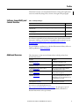
1
Reference Manual
Rockwell Automation Library of Process Objects:
Interlocks with First Out and Bypass (P_Intlk)
Version 3.1
Important User Information
Read this document and the documents listed in the additional resources section about installation, configuration, and
operation of this equipment before you install, configure, operate, or maintain this product. Users are required to
familiarize themselves with installation and wiring instructions in addition to requirements of all applicable codes, laws,
and standards.
Activities including installation, adjustments, putting into service, use, assembly, disassembly, and maintenance are required
to be carried out by suitably trained personnel in accordance with applicable code of practice.
If this equipment is used in a manner not specified by the manufacturer, the protection provided by the equipment may be
impaired.
In no event will Rockwell Automation, Inc. be responsible or liable for indirect or consequential damages resulting from the
use or application of this equipment.
The examples and diagrams in this manual are included solely for illustrative purposes. Because of the many variables and
requirements associated with any particular installation, Rockwell Automation, Inc. cannot assume responsibility or
liability for actual use based on the examples and diagrams.
No patent liability is assumed by Rockwell Automation, Inc. with respect to use of information, circuits, equipment, or
software described in this manual.
Reproduction of the contents of this manual, in whole or in part, without written permission of Rockwell Automation,
Inc., is prohibited.
Throughout this manual, when necessary, we use notes to make you aware of safety considerations.
WARNING: Identifies information about practices or circumstances that can cause an explosion in a hazardous environment,
which may lead to personal injury or death, property damage, or economic loss.
ATTENTION: Identifies information about practices or circumstances that can lead to personal injury or death, property
damage, or economic loss. Attentions help you identify a hazard, avoid a hazard, and recognize the consequence.
IMPORTANT
Identifies information that is critical for successful application and understanding of the product.
Labels may also be on or inside the equipment to provide specific precautions.
SHOCK HAZARD: Labels may be on or inside the equipment, for example, a drive or motor, to alert people that dangerous
voltage may be present.
BURN HAZARD: Labels may be on or inside the equipment, for example, a drive or motor, to alert people that surfaces may
reach dangerous temperatures.
ARC FLASH HAZARD: Labels may be on or inside the equipment, for example, a motor control center, to alert people to
potential Arc Flash. Arc Flash will cause severe injury or death. Wear proper Personal Protective Equipment (PPE). Follow ALL
Regulatory requirements for safe work practices and for Personal Protective Equipment (PPE).
Allen-Bradley, Rockwell Software, Rockwell Automation, RSLogix, Logix5000, FactoryTalk, PlantPAx, and ControlLogix are trademarks of Rockwell Automation, Inc.
Trademarks not belonging to Rockwell Automation are property of their respective companies.
Table of Contents
Preface
Software Compatibility and Content Revisions . . . . . . . . . . . . . . . . . . . . . . 5
Additional Resources . . . . . . . . . . . . . . . . . . . . . . . . . . . . . . . . . . . . . . . . . . . . . . 5
Interlocks with First Out and Bypass
(P_Intlk)
Guidelines . . . . . . . . . . . . . . . . . . . . . . . . . . . . . . . . . . . . . . . . . . . . . . . . . . . . . . . . 7
Functional Description . . . . . . . . . . . . . . . . . . . . . . . . . . . . . . . . . . . . . . . . . . . . 8
Required Files. . . . . . . . . . . . . . . . . . . . . . . . . . . . . . . . . . . . . . . . . . . . . . . . . . . . 10
Controller File . . . . . . . . . . . . . . . . . . . . . . . . . . . . . . . . . . . . . . . . . . . . . . . 10
Visualization Files . . . . . . . . . . . . . . . . . . . . . . . . . . . . . . . . . . . . . . . . . . . . 10
Controller Code . . . . . . . . . . . . . . . . . . . . . . . . . . . . . . . . . . . . . . . . . . . . . . . . . 11
Interlocks Input Structure. . . . . . . . . . . . . . . . . . . . . . . . . . . . . . . . . . . . . 11
Interlocks Output Structure . . . . . . . . . . . . . . . . . . . . . . . . . . . . . . . . . . . 12
Interlocks Local Configuration Tags . . . . . . . . . . . . . . . . . . . . . . . . . . . 13
Operations . . . . . . . . . . . . . . . . . . . . . . . . . . . . . . . . . . . . . . . . . . . . . . . . . . . . . . 13
Modes . . . . . . . . . . . . . . . . . . . . . . . . . . . . . . . . . . . . . . . . . . . . . . . . . . . . . . . 13
Alarms. . . . . . . . . . . . . . . . . . . . . . . . . . . . . . . . . . . . . . . . . . . . . . . . . . . . . . . 13
Simulation . . . . . . . . . . . . . . . . . . . . . . . . . . . . . . . . . . . . . . . . . . . . . . . . . . . 14
Execution . . . . . . . . . . . . . . . . . . . . . . . . . . . . . . . . . . . . . . . . . . . . . . . . . . . . 14
Programming Example . . . . . . . . . . . . . . . . . . . . . . . . . . . . . . . . . . . . . . . . . . . 14
Display Elements. . . . . . . . . . . . . . . . . . . . . . . . . . . . . . . . . . . . . . . . . . . . . . . . . 18
Status and Bypass Indicators. . . . . . . . . . . . . . . . . . . . . . . . . . . . . . . . . . . 19
Using Display Elements . . . . . . . . . . . . . . . . . . . . . . . . . . . . . . . . . . . . . . . 20
Faceplate . . . . . . . . . . . . . . . . . . . . . . . . . . . . . . . . . . . . . . . . . . . . . . . . . . . . . . . . 22
Operator Tab . . . . . . . . . . . . . . . . . . . . . . . . . . . . . . . . . . . . . . . . . . . . . . . . 23
Maintenance Tab. . . . . . . . . . . . . . . . . . . . . . . . . . . . . . . . . . . . . . . . . . . . . 26
Engineering Tab. . . . . . . . . . . . . . . . . . . . . . . . . . . . . . . . . . . . . . . . . . . . . . 28
Interlock Faceplate Help . . . . . . . . . . . . . . . . . . . . . . . . . . . . . . . . . . . . . . 32
Rockwell Automation Publication SYSLIB-RM004F-EN-E - April 2015
3
Table of Contents
Notes:
4
Rockwell Automation Publication SYSLIB-RM004F-EN-E - April 2015
Preface
This manual contains new and updated information. Changes throughout this
revision are marked by change bars, as shown to the right of this paragraph.
Software Compatibility and
Content Revisions
Table 1 - Summary of Changes
Topic
Page
Replaced Programming Example image showing tie back connections.
15
Added Important note concerning selections on page 2 of the Engineering tab and on the
Maintenance tab.
17
Using Display Elements: Modified introductory text concerning navigation to faceplate from
associated objects.
20
Modified image to include P_Motor Global Object Parameter Values table.
21
For the latest compatible software information and to download the Rockwell
Automation® Library, see the Product Compatibility and Download Center at
http://www.rockwellautomation.com/rockwellautomation/support/
downloads.page?.
For general library considerations, see Rockwell Automation Library of Process
Objects, publication PROCES-RM002.
Additional Resources
These documents contain more information about related products from
Rockwell Automation.
Resource
Description
PlantPAx Process Automation System Selection Guide,
publication PROCES-SG001
Provides information to assist with equipment
procurement for your PlantPAx® system.
PlantPAx Process Automation System Reference Manual,
publication PROCES-RM001
Provides characterized recommendations for
implementing your PlantPAx system.
Rockwell Automation Library of Process Objects,
publication PROCES-RM002
Provides general considerations for the Rockwell
Automation Library of Process Objects.
FactoryTalk® View Machine Edition User Manual,
publication VIEWME-UM004
Provides details on how to use this software package for
creating an automation application.
FactoryTalk View Site Edition User Manual,
publication VIEWSE-UM006
Provides details on how to use this software package for
developing and running human-machine interface
(HMI) applications that can involve multiple users and
servers, distributed over a network.
Logix5000™ Controllers Add-On Instructions Programming
Manual, publication 1756-PM010
Provides information for designing, configuring, and
programming Add-On Instructions.
You can view or download publications at
http://www.rockwellautomation.com/literature/. To order paper copies of
technical documentation, contact your local Allen-Bradley distributor or
Rockwell Automation sales representative.
Rockwell Automation Publication SYSLIB-RM004F-EN-E - April 2015
5
Preface
Notes:
6
Rockwell Automation Publication SYSLIB-RM004F-EN-E - April 2015
Interlocks with First Out and Bypass (P_Intlk)
The P_Intlk (Interlocks with First Out and Bypass) Add-On Instruction is used
to collect (sum up) the interlock conditions that stop or de-energize a running or
energized piece of equipment and prevent it from starting or being energized.
Interlocks are always evaluated to de-energize equipment. For permissive
conditions that must be made to start the equipment, but are ignored once the
equipment is running, use the Permissives (P_Perm) Add-On Instruction.
Faceplate
Global Object
Add-On Instruction
Rockwell Automation Publication SYSLIB-RM004F-EN-E - April 2015
7
Interlocks with First Out and Bypass (P_Intlk)
Guidelines
Use this instruction in these situations:
• You have multiple interlock conditions or cascaded interlock conditions
(an interlock hierarchy) that stop some equipment (motor, valve, drive) or
keep it from starting. Link the conditions to P_Intlk inputs, and link the
P_Intlk status bits to the Inp_IntlkOK and Inp_NBIntlkOK inputs of the
equipment.
• You need a first-out indication of the interlock condition that shuts down
the equipment.
• You want configurable text descriptions of shutdown conditions or other
features of the P_Intlk faceplate.
Do not use this instruction in these situations:
• You have conditions that prevent the equipment from starting, but are
ignored once the equipment is running. These conditions are permissive,
not interlock conditions. Use the P_Perm instruction instead.
• You have only one interlock condition for the equipment. Connect the
condition directly to the interlock input on the device.
8
Rockwell Automation Publication SYSLIB-RM004F-EN-E - April 2015
Interlocks with First Out and Bypass (P_Intlk)
Functional Description
The following diagram shows the functional characteristics of the P_Intlk AddOn Instruction.
The primary operations of the P_Intlk Add-On Instructions and its faceplate are
the following:
• Interlock input OK Check: Each input is compared with its configured
OK state. If the input is not in its OK state, it raises an interlock condition
unless bypassed by Maintenance. (See Interlock Bypass on page 8.)
• Interlock Condition Latching: If the input is configured as latched, the
interlock condition is latched in until reset unless the latch defeat input is
true. See Latch Defeat on page 9. If the input is not configured as latched,
the interlock condition clears when the input is again in its OK state.
• Interlock Bypass: If the input is configured as able to be bypassed and
interlocks are bypassed, the input does not raise an interlock condition,
even if it is not in its OK state. If the input is configured as not able to be
bypassed or if interlocks are not bypassed, the input raises an interlock
condition.
Engineering configures which interlocks are allowed to be bypassed.
Maintenance then picks the ones to bypass from the interlocks allowed by
Engineering.
• First Out: If no interlock conditions are raised (OK to run), the first
interlock condition to be raised is marked as the first out. If multiple such
interlock conditions are raised in the same scan, they are all marked as
first out.
Rockwell Automation Publication SYSLIB-RM004F-EN-E - April 2015
9
Interlocks with First Out and Bypass (P_Intlk)
• Latch Defeat: A latch defeat function is provided to reduce the number of
operator actions that are required to start equipment. The latch defeat
input is set when the equipment is not running. When the latch defeat
input is true, the latched configuration of inputs is ignored, and all
interlock conditions clear when their corresponding inputs are in their OK
states. This action saves the operator from having to reset before starting
the equipment. When the equipment starts, the latch defeat input is
turned off. Then, if an interlock condition configured as latched shuts
down the equipment, it remains latched until reset.
IMPORTANT
To prevent loss of information about what shut down the equipment,
the latch defeat input is not processed until after any latched interlocks
(that occurred when the latch defeat was off) have been reset.
• Summary Status: The P_Intlk Add-On Instruction summarizes its 16
interlock input conditions into two primary status bits: Sts_IntlkOK,
which indicates that all interlock conditions are clear (ready to run), and
Sts_NBIntlkOK, which indicates that all interlock conditions that cannot
be bypassed are clear (ready to run if interlocks are bypassed).
IMPORTANT
Whether interlocks are bypassed or not is determined by the
downstream equipment instructions. The P_Intlk instruction simply
provides the two summary status bits. These two bits are to be wired or
mapped to the equipment control logic.
• Faceplate: The P_Intlk Add-On Instruction faceplate displays the
interlock condition state of each input and whether it is bypassed, and
shows the overall interlock (summary) status. The Engineering tab of the
faceplate lets you configure the P_Intlk Add-On Instruction for OK state
configuration, latch configuration, configuration of interlocks that can be
bypassed, and the text that is associated with each interlock condition
input. You can also configure a navigation tag for each interlock condition.
If you enable navigation, the condition text on the Operator tab of the
faceplate can be clicked to access the faceplate for the corresponding tag.
10
Rockwell Automation Publication SYSLIB-RM004F-EN-E - April 2015
Interlocks with First Out and Bypass (P_Intlk)
Add-On Instructions are reusable code objects that contain encapsulated logic
that can streamline implementing your system. This code lets you create your
own instruction set for programming logic as a supplement to the instruction set
provided natively in the ControlLogix® firmware. An Add-On Instruction is
defined once in each controller project, and can be instantiated multiple times in
your application code as needed.
Required Files
Controller File
The P_Intlk_3_1-00_AOI.L5X Add-On Instruction must be imported into the
controller project to be used in the controller configuration. The service release
number (boldfaced) can change as service revisions
are created.
Visualization Files
The following files for this Add-On Instruction can be downloaded from the
Product Compatibility and Download Center at
http://www.rockwellautomation.com/rockwellautomation/support/pcdc.page.
IMPORTANT
Files must be imported in the following order: image files, then global object
files, and then graphic files. This order is required to configure the visualization
files properly.
Table 2 - P_Intlk Visualization File Types
Application Type
File Type
FactoryTalk View SE Software
FactoryTalk View ME Software
Description
Graphics - Displays
GFX
(RA-BAS) P_Intlk-Faceplate
(RA-BAS-ME) P_Intlk-Faceplate
The faceplate display that is used for the
object.
(RA-BAS) P_IntlkPerm-Help
(RA-BAS-ME) P_IntlkPerm-Help
Interlock/Permissives information that is
accessed from the P_Intlk or P_Perm Help
faceplate.
(RA-BAS) Common Faceplate Objects
(RA-BAS-ME) Common Faceplate Objects
Common global objects that are used on all
Process Object faceplates.
(RA-BAS) Process Interlock Objects
(RA-BAS-ME) Process Interlock Objects
Global objects that are used for managing
interlocks and permissives on Process Object
faceplates.
Graphics - Global
Objects
GGFX
Graphics - Images
PNG
All .png files in the images folder
All .png files in the images folder
The common icons that are used in the global
objects and faceplates for all Process Objects.
When PNG graphic formats are imported,
they are renamed like a BMP file but retain a
PNG format.
HMI Tags
CSV
N/A
FTVME_PlantPAxLib_Tags_3_1_00.csv(1)
These tags must be imported into the
FactoryTalk View ME project to support
switching tabs on any Process Object
faceplate.
Macros
MCR
NavToObject
N/A
This macro must be imported into the
FactoryTalk View SE project to support
faceplate-to-faceplate navigation by
tagname.
(1) The service release number (boldfaced) can change as service revisions are created.
Rockwell Automation Publication SYSLIB-RM004F-EN-E - April 2015
11
Interlocks with First Out and Bypass (P_Intlk)
This section describes the parameter references for this Add-On Instruction.
Controller Code
Interlocks Input Structure
Input parameters include the following:
• Input data elements (Inp_) are typically used to connect field inputs from
I/O modules or signals from other objects.
• Configuration data elements (Cfg_) are used to set configurable
capabilities and features of the instruction.
• Commands (PCmd_, OCmd_, MCmd_) are used by program logic,
operators, and maintenance personnel to request instruction actions.
• Settings (PSet_, OSet_, MSet_) are used by program logic, operators, and
maintenance personnel to establish runtime setpoints, thresholds, and so
forth. A Setting (without a leading P, O, or M) establishes runtime settings
regardless of role or mode.
Table 3 - P_Intlk Input Parameters
Input Parameter
Data
Type
EnableIn
BOOL
Inp_Intlk00…Inp_Intlk15
BOOL
Inp_BypActive
Default
Description
1
Ladder Diagram:
If the rung-in condition is true, the instruction’s Logic routine executes. If the rungin condition is false, the instruction’s EnableInFalse routine executes.
Function Block Diagram:
If true, or not connected, the instruction’s Logic routine executes. If the parameter
is exposed as a pin and wired, and the pin is false, the instruction’s EnableInFalse
routine executes.
Structured Text:
No effect. The instruction’s Logic routine executes.
0
Interlock condition inputs - If Input is not in the OK state defined by Cfg_OKState
and not bypassed (if able to be bypassed per Cfg_Bypassable), then the
appropriate interlock status (Sts_IntlkOK and Sts_NBIntlkOK) are set to 0 to stop
the equipment.
BOOL
0
1 = Interlock Bypassing is currently active.
Inp_LatchDefeat
BOOL
0
Latch Defeat 1 = Do not latch inputs even if configured for latching.
Inp_Reset
BOOL
0
Input parameter that is used to programmatically reset latched interlocks. When
set to 1, all latched interlocks that require a reset are reset.
Cfg_OKState
INT
2#0000_0000_
0000_0000
Bits determine the state (0 or 1) of each input that is OK to run.
Cfg_Latched
INT
2#0000_0000_
0000_0000
Set bits determine the conditions that are latched (sealed in).
Cfg_Bypassable
INT
2#0000_0000_
0000_0000
Set bits determine the conditions that can be bypassed.
Cfg_HasNav
INT
2#0000_0000_
0000_0000
Set bits determine the Navigation buttons that are enabled.
Cfg_PCmdClear
BOOL
1
When this parameter is 1, program commands are cleared once they are acted
upon. When set to 0, program commands remain set until cleared by the
application program logic.
IMPORTANT: Clearing this parameter online can cause unintended program
command execution.
12
Alias For
Wrk_Inp.0…Wrk_Inp.15
Rockwell Automation Publication SYSLIB-RM004F-EN-E - April 2015
Interlocks with First Out and Bypass (P_Intlk)
Table 3 - P_Intlk Input Parameters
Input Parameter
Data
Type
Alias For
Default
Description
MSet_Bypass00…
MSet_Bypass15
BOOL
Wrk.MSet.0…Wrk.MSet.15
0
Maintenance Bypass Toggle for Interlock Cond. 00…Cond.15: 1 = Bypass.
Maintenance uses these bits to determine which individual interlocks are
bypassed.
PCmd_Reset
BOOL
0
• Set PCmd_Reset to 1 to reset latched interlocks
• This parameter is reset automatically if Cfg_PCmdClear = 1
OCmd_Reset
BOOL
0
Operator Command to reset latched interlocks.
Interlocks Output Structure
Output parameters include the following:
• Status data elements (Sts_) are bit outputs of the instruction for use by the
HMI. Status bits can also be used by other application logic.
• Ready data elements (Rdy_) are bit outputs of the instruction that are used
by the HMI to enable or disable command buttons and entry fields.
Table 4 - P_Intlk Output Parameters
Output Parameter
Data Type
Description
EnableOut
BOOL
Enable Output: The EnableOut signal is not manipulated by this instruction. Its output state always reflects EnableIn input
state.
Sts_IntlkOK
BOOL
Overall Interlock Status:
1 = OK to run
0 = Stop
Sts_NBIntlkOK
BOOL
Interlock (cannot be bypassed) Status (1 = All NB interlocks OK to run).
Sts_BypActive
BOOL
1 = Interlock Bypassing Active (interlocks that can be bypassed are ignored).
Sts_Intlk
INT
Individual Interlock Status:
bit = 1 = Stop
bit = 0 = OK
Sts_FirstOut
INT
Interlock First Out Status (bit = 1 is First Not-OK condition).
Rdy_Reset
BOOL
1 = Ready to receive OCmd_Reset (reset required).
P_Intlk
BOOL
Unique Parameter Name for auto-discovery.
Rockwell Automation Publication SYSLIB-RM004F-EN-E - April 2015
13
Interlocks with First Out and Bypass (P_Intlk)
Interlocks Local Configuration Tags
Configuration parameters that are array, string, or structure data types cannot be
configured as parameters for Add-On Instructions. Configuration parameters of
these types appear as local tags to the Add-On Instruction. Local tags can be
configured through the HMI faceplates or in RSLogix™ 5000 software. Open the
instruction logic of the Add-On Instruction instance and then open the Data
Monitor on a local tag to accomplish this configuration. These parameters
cannot be modified by using controller logic or RSLogix 5000 software export/
import functionality.
Table 5 - P_Intlk Local Configuration Tags
Tag Name
Data Type
Cfg_CondTxt
Cfg_CondTxt[0]
Cfg_CondTxt[1]…
Cfg_CondTxt[15]
STRING_20[16]
Cfg_Desc
STRING_40
'Interlocks with First Out' Description for display on HMI. This string is shown in the title bar of the faceplate.
Cfg_Label
STRING_20
'Interlocks'
Label for graphic symbol that is displayed on HMI. This string appears on the graphic symbol.
Cfg_NavTag
STRING_20[16]
''
Tag names for destinations of 16 navigation buttons.
Cfg_Tag
STRING_20
'P_Intlk'
Tag name for display on the HMI. This string is shown in the title bar of the faceplate.
Operations
Default
Description
Short HMI descriptions of 16 interlock conditions.
'Enter Description #0'
''
This section describes the primary operations for Add-On Instructions.
Modes
The P_Intlk Add-On Instruction does not have modes and does not contain a
P_Mode instruction instance. The Operator and Program reset commands for
the latched inputs are accepted at any time.
Alarms
The P_Intlk Add-On Instruction does not generate any alarms. The individual
input conditions can be alarmed, if necessary, in other logic before they are sent
to the inputs of the P_Intlk instruction. In many applications, status bits from
P_AIn Analog Input or P_DIn Discrete Input instructions are sent to the
P_Intlk inputs, and those instructions provide alarms.
ATTENTION: Status bits are normally used as interlock conditions. Use alarm
bits as interlock conditions only if you intend that the interlock condition be
ignored when the corresponding alarm is disabled, suppressed, or shelved.
14
Rockwell Automation Publication SYSLIB-RM004F-EN-E - April 2015
Interlocks with First Out and Bypass (P_Intlk)
Simulation
The P_Intlk Add-On Instruction does not have a Simulation capability.
Execution
The following table explains the handling of instruction execution conditions.
Condition
Description
EnableIn False (false rung)
Processing for EnableIn False (false rung) is handled by setting the
summary All interlocks OK and All interlocks (cannot be bypassed) OK
status outputs to false (0). The individual interlock bit status and first out
outputs are left in their last state.
Powerup (prescan, first scan)
The latch and first out states of the P_Intlk Add-On Instruction are
maintained through a power-down/power-up or Run/Program/Run cycle.
Any commands that are received before first scan are discarded.
Postscan (SFC transition)
No SFC postscan logic is provided.
See the Logix5000 Controllers Add-On Instructions Programming Manual,
publication 1756-PM010, for more information.
Rockwell Automation Publication SYSLIB-RM004F-EN-E - April 2015
15
Interlocks with First Out and Bypass (P_Intlk)
Programming Example
This example uses the P_Intlk instruction to concentrate the interlock conditions
that allow the functioning of the refiner plates that are used for grinding wood as
part of the pulp manufacturing process.
Perform the following steps to import an Add-On Instruction to your project.
1. Right-click 'Add-On Instructions' and select 'Import Add-On
Instruction…'
2. On the Import Add-On Instruction dialog box, select the P_ Intlk
instruction and click Import.
3. Add the P_ Intlk instruction to your project:
a. Click the Add-On tab on the Language Element toolbar.
b. Click the P_ Intlk instruction.
c. Also add the P_ Motor instruction that controls the refiner plates.
4. Double-click the interlock instruction name and create the tag name for it.
The naming convention that makes navigation from the motor faceplate
work automatically is to use the motor’s tag name followed by _Intlk.
5. Create the input references necessary to ensure the appropriate operation
of the refiner plates and create their appropriate tags.
6. Expose the Sts_BypActive pin on P_Motor. Wire this pin back to
Inp_BypActive on P_Intlk, and mark this wire 'Assume Data Available'.
The following image is what the instruction looks like when connected
correctly.
7. Save, download, and run your Logix application.
16
Rockwell Automation Publication SYSLIB-RM004F-EN-E - April 2015
Interlocks with First Out and Bypass (P_Intlk)
8. In your HMI application, add a P_Motor motor graphic object from
P_Motor Graphics Library.ggfx and right-click it.
9. From the list, select “Global Object Parameter Values”
10. Associate the created tag for P_Motor of the Refiner Plates in the
controller with the graphic object in the HMI:
a. On the first line of the Global Object Parameter Value table, type its
name.
b. On the second line, type the name of the shortcut to the controller
enclosed by brackets.
c. Fill in additional parameters as desired.
Because of the naming convention, the connection will be made
automatically and the interlock settings will be associated with the
refiner plates motor.
11. Save and your HMI application.
12. Run your HMI application and click the motor graphic object. If the
Quick display appears, click the 'go to faceplate' button.
13. On the P_Motor faceplate, click the Engineering tab and go to page 2.
Rockwell Automation Publication SYSLIB-RM004F-EN-E - April 2015
17
Interlocks with First Out and Bypass (P_Intlk)
14. Check “Enable navigation to interlock object”.
The Interlock button is enabled.
15. On the P_Motor faceplate, click the Interlock button to open the P_Intlk
faceplate. On the P_Intlk faceplate, click the Engineering tab, and perform
the following:
a. Name the interlocks accordingly.
b. Select the appropriate state under 'OK State'.
c. Indicate which interlocks can be bypassed.
18
Rockwell Automation Publication SYSLIB-RM004F-EN-E - April 2015
Interlocks with First Out and Bypass (P_Intlk)
d. Indicate which interlocks must be reset.
IMPORTANT
Specific inputs can be bypassed on the maintenance tab based on selections on
page 2 of the Engineering tab (see Engineering Tab Page 2 on page 30).
When bypass is enabled, it bypasses only those set on the Maintenance tab
(Maintenance Tab on page 26).
Rockwell Automation Publication SYSLIB-RM004F-EN-E - April 2015
19
Interlocks with First Out and Bypass (P_Intlk)
Display Elements
A display element (global object) is created once and can be referenced multiple
times on multiple displays in an application. When changes are made to the
original (base) object, the instantiated copies (reference objects) are
automatically updated. Use of global objects, with tag structures in the
ControlLogix system, aid consistency and save engineering time.
Display Element Name
Display Element
GO_P_Intlk
Description
Standard Interlock Global Object.
Graphic symbols are provided for use on end-user process graphic displays.
Interlock graphic symbols have the following common attributes.
Status Indicator
Bypass Indicator
The Interlock graphic symbol displays the current summary state of the
interlocks and whether interlocks that can be bypassed are bypassed. These
indicators are described in detail in Status and Bypass Indicators on page 19.
The overall graphic symbol includes a touch field that opens the instruction’s
faceplate. In the SE version of the library, pausing the pointing device over the
graphic symbol displays a tooltip that describes the symbol’s function.
20
Rockwell Automation Publication SYSLIB-RM004F-EN-E - April 2015
Interlocks with First Out and Bypass (P_Intlk)
Status and Bypass Indicators
The Status Indicator icon changes color and shape that is based on the state of the
interlock input conditions, and the Bypass Indicator shows whether interlock
conditions that can be bypassed are currently being bypassed.
Background
Description
Not ready to run or energize. One or more interlock
conditions are not OK.
Ready to run or energize. One or more conditions that can
be bypassed are not OK, but these conditions are
bypassed. All conditions that cannot be bypassed are OK.
Ready to run or energize. All interlock conditions are OK.
Ready to run or energize, and all interlock conditions are
OK, but be aware that conditions that can be bypassed are
being bypassed and the equipment is not shut down.
The P_Intlk instruction does not have bypass commands, as they are in the
associated device instruction. If you would like the graphic symbol and faceplate
to display the equipment’s bypass state, connect the equipment’s bypass status to
the P_Intlk instructions Inp_BypActive input.
Rockwell Automation Publication SYSLIB-RM004F-EN-E - April 2015
21
Interlocks with First Out and Bypass (P_Intlk)
Using Display Elements
Normally, navigation to the P_Intlk faceplate is included on the faceplate for the
associated motor, drive, or other object. However, a graphic symbol for the
P_Intlk instruction can be found in the global object file (RA-BAS) Process
Interlock Objects.ggfx. Follow these steps to use the graphic symbol.
1. Copy the global object from the global object file and paste it in the
display file.
22
Rockwell Automation Publication SYSLIB-RM004F-EN-E - April 2015
Interlocks with First Out and Bypass (P_Intlk)
2. In the display, right-click the global object and choose Global Object
Parameter Values.
The Global Object Parameter Values dialog box appears.
The global object parameters are as follows.
Parameter
Required
Description
#102
Y
Object tag to point to the name of the associated object Add-On
Instruction in the controller.
#103
Y
Path that is used for display navigation features to other objects. Include
program scope if tag is a program scope tag.
#120
N
Additional parameter to pass to the display command to open the
faceplate. Typically used to define position for the faceplate.
#121
N
Additional parameter to pass to the display command to open the
faceplate. When you define the X and Y coordinate, separate parameters so
that #120 defines X and #121 defines Y. This definition lets these same
parameters to be used in subsequent display commands that originate
from the faceplate.
3. Type the tag or value in the Value column as specified in the Description
column.
TIP
Click the ellipsis (…) to browse and choose a tag.
Values for items marked ‘(optional)’ can be left blank.
4. Click OK.
Rockwell Automation Publication SYSLIB-RM004F-EN-E - April 2015
23
Interlocks with First Out and Bypass (P_Intlk)
Faceplate
The P_Intlk faceplate consists of three tabs and each tab consists of one or more
pages.
Each faceplate contains the value of local configuration tags Cfg_Tag and
Cfg_Desc in the title bar.
The Operator tab is displayed when the faceplate is initially opened. Click the
appropriate icon at the top of the screen to access a specific tab.
Exit
Maintenance
Operator
Engineering
Help
The faceplate provides the means for operators, maintenance workers, engineers,
and others to interact with the P_E300Ovld instruction instance. You can also
view its status and values and manipulate it through its commands and settings.
When a given input is restricted via FactoryTalk View security, the required user
Security Code letter is shown in the faceplate description tables.
24
Rockwell Automation Publication SYSLIB-RM004F-EN-E - April 2015
Interlocks with First Out and Bypass (P_Intlk)
Operator Tab
The Faceplate initially opens to the Operator (‘Home’) Tab. From here, an
operator can monitor the device status.
The Operator tab shows the following information:
• A status indicator, identical to the one on the graphic symbol, shows the
current interlock state (all conditions met, non-bypassed conditions met,
or some conditions not met)
• Interlock Bypass status indicator
• Each configured interlock along with the current state of the interlock
• Latch Defeat status indicator
The following figure shows the Operator tab in a non-bypassed condition.
Status Indicator
Latch Defeat Status
Indicator
Bypass Status Indicator
Reset Button
Condition OK
Condition Not OK
First-Out Indicator
If navigation is enabled, click a condition to open the faceplate of the object that
is associated with the condition.
Rockwell Automation Publication SYSLIB-RM004F-EN-E - April 2015
25
Interlocks with First Out and Bypass (P_Intlk)
The following figure shows the Operator tab in a bypassed condition.
Bypass Indicator
Condition Bypassed, Input OK
Condition Bypassed, Input Not OK
The following table lists the functions on the Operator tab.
Table 6 - Operator Tab Description
Function
Click Interlock Condition text
26
Action
Security Required
Resets interlocks that are latched.
Normal Operation of
Devices (Code A)
Click to open the faceplate for the
associated tag.
See Engineering Tab Page 3 on page 31 for
information on how to enable navigation
for interlock conditions.
None
Rockwell Automation Publication SYSLIB-RM004F-EN-E - April 2015
Interlocks with First Out and Bypass (P_Intlk)
Table 7 - Operator Tab Status Indicators
Indicator
Description
Condition OK
Condition Not OK
Bypassed, but OK
Not OK, but bypassed
Rockwell Automation Publication SYSLIB-RM004F-EN-E - April 2015
27
Interlocks with First Out and Bypass (P_Intlk)
Maintenance Tab
Maintenance personnel use the information and controls on the Maintenance tab
to make adjustments to device parameters. They also troubleshoot and
temporarily work around device problems, and disable the device for routine
maintenance.
IMPORTANT
Only interlocks with white checkboxes can be individually bypassed. These
interlocks are set up using the 'Can Bypass' column on page 2 of the
Engineering tab. (See Engineering Tab Page 2 on page 30.)
Individual Enable
Bypass Checkboxes
Interlocks
28
Rockwell Automation Publication SYSLIB-RM004F-EN-E - April 2015
Interlocks with First Out and Bypass (P_Intlk)
The following table lists the functions on the Maintenance tab.
Table 8 - Maintenance Tab Descriptions
Function
Action
Security
Enable Bypass
Click an interlock condition that can
be bypassed, one that has a white
checkbox, to enable bypass of that
individual interlock.
See Engineering Tab Page 2 on
page 30 for information on how to
make interlock conditions active.
Bypass
Cfg_Bypassable
Permissives
and Interlocks
(Code H)
Rockwell Automation Publication SYSLIB-RM004F-EN-E - April 2015
Configuration Parameters
29
Interlocks with First Out and Bypass (P_Intlk)
Engineering Tab
The Engineering tab provides access to device configuration parameters and
ranges, options for device and I/O setup, displayed text, and
faceplate-to-faceplate navigation settings, for initial system commissioning or
later system changes.
The Engineering tab is divided into three pages.
Engineering Tab Page 1
On page 1 of the Engineering tab, you can configure the description, label, and
tag for the device.
Configure Description,
Label, and Tag
30
Rockwell Automation Publication SYSLIB-RM004F-EN-E - April 2015
Interlocks with First Out and Bypass (P_Intlk)
The following table lists the functions on page 1 of the Engineering tab.
Table 9 - Engineering Tab Page 1 Descriptions
Function
Action
Security
Configuration Parameters
Description
Type the text description of the
interlock set. It appears on the title
bar of the faceplate.
Engineering
Configuration
(Code E)
Cfg_CondTxt[0]…Cfg_CondTxt[15]
Label
Type the label to show on the graphic
symbol.
Cfg_Label
Tag
Type the tag name to show on the
faceplate and Tooltip.
IMPORTANT: Pausing the mouse
over this field displays a tool tip with
the configured Logix tag/path.
Cfg_Tag
Clear Program
Commands on
Receipt
Check to clear Program commands on
receipt.
Cfg_PCmdClear
Rockwell Automation Publication SYSLIB-RM004F-EN-E - April 2015
31
Interlocks with First Out and Bypass (P_Intlk)
Engineering Tab Page 2
Up to 16 interlock inputs can be configured on page 2 of the Engineering tab. For
each interlock, the following can be configured.
Table 10 - Engineering Tab Page 2 Descriptions
32
Function
Action
Security
Required
Configuration Parameters
Descriptions
Type the text description of each
interlock condition used. The
interlocks with text entered appear
on the Operator tab of the faceplate.
If the text for a condition is empty
(null), that interlock is not shown.
Engineering
Configuration
(Code E)
Cfg_Desc
OK State
Selects the state of the corresponding
interlock that is the OK to Run state.
Cfg_OKState
Can Bypass
Check to indicate that the
corresponding interlock can be
bypassed.
See Maintenance Tab on page 26 for
information on bypassing interlocks.
Cfg_Bypassable
Must Reset
Check to indicate that the
corresponding interlock is latched
and must be reset.
Cfg_Latched
Rockwell Automation Publication SYSLIB-RM004F-EN-E - April 2015
Interlocks with First Out and Bypass (P_Intlk)
Engineering Tab Page 3
Navigation for the 16 interlock inputs is configured on page 3 of the Engineering
tab. For each interlock, the following can be configured.
Table 11 - Engineering Tab Page 3 Descriptions
Function
Action
Security
Required
Configuration Parameters
Allow Navigation to
Interlock Input
Objects
Check to enable navigation for the
corresponding interlock input object.
Engineering
Configuration
(Code E)
Cfg_HasNav
Navigation Tag
Type the name of the tag to navigate
to when the interlock description on
the Operator tab is clicked.
Rockwell Automation Publication SYSLIB-RM004F-EN-E - April 2015
Cfg_NavTag[0]…Cfg_NavTag[15]
33
Interlocks with First Out and Bypass (P_Intlk)
Interlock Faceplate Help
34
Rockwell Automation Publication SYSLIB-RM004F-EN-E - April 2015
Rockwell Automation Support
Rockwell Automation provides technical information on the Web to assist you in using its products.
At http://www.rockwellautomation.com/support you can find technical and application notes, sample code, and links to
software service packs. You can also visit our Support Center at https://rockwellautomation.custhelp.com/ for software
updates, support chats and forums, technical information, FAQs, and to sign up for product notification updates.
In addition, we offer multiple support programs for installation, configuration, and troubleshooting. For more
information, contact your local distributor or Rockwell Automation representative, or visit
http://www.rockwellautomation.com/services/online-phone.
Installation Assistance
If you experience a problem within the first 24 hours of installation, review the information that is contained in this
manual. You can contact Customer Support for initial help in getting your product up and running.
United States or Canada
1.440.646.3434
Outside United States or Canada
Use the Worldwide Locator at http://www.rockwellautomation.com/rockwellautomation/support/overview.page, or contact your local
Rockwell Automation representative.
New Product Satisfaction Return
Rockwell Automation tests all of its products to help ensure that they are fully operational when shipped from the
manufacturing facility. However, if your product is not functioning and needs to be returned, follow these procedures.
United States
Contact your distributor. You must provide a Customer Support case number (call the phone number above to obtain one) to your
distributor to complete the return process.
Outside United States
Please contact your local Rockwell Automation representative for the return procedure.
Documentation Feedback
Your comments will help us serve your documentation needs better. If you have any suggestions on how to improve this
document, complete this form, publication RA-DU002, available at http://www.rockwellautomation.com/literature/.
Rockwell Automation maintains current product environmental information on its website at
http://www.rockwellautomation.com/rockwellautomation/about-us/sustainability-ethics/product-environmental-compliance.page.
Rockwell Otomasyon Ticaret A.Ş., Kar Plaza İş Merkezi E Blok Kat:6 34752 İçerenköy, İstanbul, Tel: +90 (216) 5698400
Publication SYSLIB-RM004F-EN-E - April 2015
Supersedes Publication SYSLIB-RM004E-EN-E - August 2014
Copyright © 2015 Rockwell Automation, Inc. All rights reserved. Printed in the U.S.A.