1
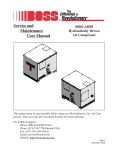
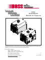
Service and
Maintenance
User Manual
BOSS
BA435 PISTON
Hydraulic Air Compressor
This manual must be read carefully before using your Boss Industries Air Compressor.
Store in a safe and convenient location for future reference.
For technical support:
Phone: (800) 635-6587 (USA)
Phone: (219) 324-7776 (Outside USA)
Fax: (877) 254-4249 (USA)
[email protected] (email)
http://www.bossair.com (website)
309395
1/14/2015 KWB
2
309395
Contents
Revision List........................................................................................................5
Welcome........................................................................................................6
Safety Information...............................................................................................7
Warnings, safety rules, and hazards...............................................................7
Specifications...............................................................................................10
Description of Components...............................................................................11
Installation & Operation...................................................................................12
Installation............................................................................................12
Before Starting...........................................................................................14
Initial Start-up & Test.................................................................................16
Maintenance................................................................................................17
Overview..............................................................................................17
Recommended Spare Parts List.................................................................17
Maintenance Schedule................................................................................18
Lubrication Recommendation....................................................................19
Compressor Oil .........................................................................................20
Air Intake Filter...........................................................................................20
Hydraulic Oil Cooler..................................................................................20
Piston Ring Replacement............................................................................21
Oil Pump Replacement...............................................................................23
Crankshaft and Bearing Replacement..........................................................24
Troubleshooting...........................................................................................26
General Tips..............................................................................................26
Contacting Boss Ind...................................................................................27
Where To Find Specific Machine Information.............................................27
3
309395
Warranty..............................................................................................................29
Warranty Statement....................................................................................30
Summary of Main Warranty Points..............................................................31
Return Goods Instructions.........................................................................32
Preparation of Part Return..........................................................................32
Filing Procedures.......................................................................................32
Other Info..................................................................................................33
Transit Damage..........................................................................................33
Drawings.....................................................................................................35
Frame System............................................................................................36
Oil Cooler System......................................................................................38
Piston System............................................................................................40
Air Inlet System..........................................................................................42
Discharge System......................................................................................44
Canopy System..........................................................................................46
Oil Drain....................................................................................................48
Mounting System.......................................................................................50
Decal System.............................................................................................52
Wiring Diagram..........................................................................................54
4
309395
Revision List
D ATE
LOCATION D ESCPR IPTION OF CHAN GE
5
IN ITIALS
309395
Welcome
General Information
Thank you for choosing the Boss BA435 Hydraulic Air Compressor.
Before operating this compressor, read over this manual and become
well acquainted with your new machine. Doing this will increase your
safety and maximize the life of the machine.
While this manual is written to be as accurate as possible, Boss strives to
continually improve the efficiency and performance of its machines. As a
result, sometimes there may be slight differences between a given version
of the manual and the machine.
Service and
Maintenance
User Manual
BOSS
BA435 PISTON
Hydraulic Air Compressor
This manual must be read carefully before using your Boss Industries Air Compressor.
Store in a safe and convenient location for future reference.
For technical support:
Phone: (800) 635-6587 (USA)
Phone: (219) 324-7776 (Outside USA)
Fax: (877) 254-4249 (USA)
[email protected] (email)
http://www.bossair.com (website)
309395
01/24/2012 CRH
Boss BA435 Hydraulic Air Compressor
The Boss BA435 is a compact, strategically designed system. It integrates all major components on a single
frame, which is enclosed in a tough, weather-resistant canopy.
The BA435 Piston design provides output of up to 35
CFM (cubic feet of air per minute) at up to a maximum
of 150 PSI (pounds per square inch). High output at
relatively low GPM (gallons per minute) translates into
the most efficient, quiet, and reliable system in its class,
designed to handle virtually any application.
The BA435 Piston also has enhanced safety features
offering applications designed to protect your most
valuable resource - your operating crew. To prevent
overheating, a high temperature switch will shut down
the machine in the event of high discharge
temperatures.
6
309395
Safety
IMPORTANT READ BEFORE OPERATING EQUIPMENT
Remember, safety is basically common sense. While there are standard safety rules, each situation has its
own peculiarities that cannot always be covered by rules. Therefore with your experience and common
sense, you are in a position to ensure your and others safety. Lack of attention to safety can result in:
accidents, personal injury, reduction in efficiency and worst of all – Loss of Life. Watch for safety hazards
and correct them promptly.
Understanding the proper operation of this equipment is critical to its safe operation. The owner, lessor or
operator of this equipment is hereby notified and forewarned that any failure to observe the safety and
operating guidelines may result in injury and/or damage. Boss expressly disclaims responsibility or liability
for any injury or damage caused by failure to observe these specified precautions or by failure to exercise
the ordinary caution and due care required while operating or handling this equipment, even though not
expressly specified.
In addition to following these safety guidelines, the operator should follow any company specific guidelines
and procedures. Consult your immediate supervisor for specific company safety guidelines and/or procedures.
The following safety symbols are used throughout the manual to draw attention to important information. If
the information is not carefully read and the instructions are not followed, severe injury, death, and/or
damage to property and equipment may occur.
Indicate[s] an imminently hazardous situation, which, if
not avoided, will result in death or serious injury.
Indicate[s] a potentially hazardous situation, which, if not
avoided, could result in death or serious injury.
Indicate[s] a potentially hazardous situation, which, if not
avoided, could result in minor or moderate injury.
Indicate[s] a potentially unsafe situation or practice,
which, if not avoided can result in property and/or
equipment damage only.
7
309395
Safety
The following safety precautions are a general guide to safe operation of the equipment.
Read and understand the operations manual and all other safety
instructions before using this equipment. Failure to follow
operating instructions and/or failure to follow maintenance procedures and intervals could result in personal injury, death, and/or
damage to equipment and property.
Pressurized System. Do not attempt to remove any compressor
parts without first completely relieving entire system of pressure.
Do not attempt to service any part of the equipment while in
operation. Never attempt to repair or modify any pressure vessel
or device.
System contains hot oil. The compressor system must be shut off
prior to servicing. Open the service valve to ensure complete relief
of system air pressure and stored energy. Then permit system to
cool down prior to adding compressor oil or servicing the unit.
Do not use air from this compressor for breathing or food processing. Air from this compressor will cause severe injury if used for
breathing or food processing.
The compressor is designed to compress air only. Do not attempt
to compress other gases. Compression of other gases may create
a situation where an explosion or fire may occur.
Do not use flammable solvents for cleaning compressor parts as
this can cause the unit to ignite or explode during operation. Keep
combustibles out of and away from compressor inlet, and any
associated enclosures.
8
309395
Safety
Never disable, override, or remove safeties, either temporarily or permanently.
Do not modify pressure switches to operate equipment at a higher pressure
than specified. When using a hose reel, the complete system must be designed
with safety valves in accordance with OSHA Regulation 1910.169.
Never leave the machine running unattended or leave a tool connected to an
air hose when not using. Relieve system of all stored air pressure after use.
Never adjust the pressure switch to a setting of greater than 150 PSI. Operating the compressor at greater than 150 PSI may result in personal injury and
property damage.
Mount the compressor in a stable location capable of supporting 180 lbs.
Slight vibration may occur during operation and the machine may move if not
securely mounted.
When using tools, maintain secure footing at all times. Do not overreach or
awkwardly use air tools.
Prior to moving vehicle to the next work site, drain the air tank. To prevent
the collection of water in the tank drain daily.
Use only Boss approved replacement parts.
9
309395
Specifications
POWER SOURCE
HYDRAULIC MOTOR
OPERATING SPEED
1400 RPM MAX.
CYLINDER CONFIG.
V4 Piston
OIL CAPACITY
1 1/3 QTS
DIM ENSIONS
26 1/2"L x 19 1/8"H x 19 3/4"W
WEIGHT
180 LBS.
DELIVERY @ 100 PSI
35 C F M
HYDRAULIC RESERVOIR
REQ. *
12 GALLON MINIMUM
COOLING
AIR
NORM AL GPM @ 1400 RPM
9.3 GPM
FAN DIAM ETER
14 1/8"
NORM AL OPERATING PSI
1850 PSI
M AXIM UM PSI
2400 P S I
* Hydraulic reservoir requirement for compressor only. Additional capacity will be needed to other hydraulic
equipment.
SPECIFICATIONS SUBJECT TO CHANGE WITHOUT PRIOR NOTICE
22.91
20.12
19.74
26.50
1.00
28.60
– BA435 system is to run intermittently.
– When the BA435 is installed with other hydraulic drive equipment it will require a dedicated flow line.
– If other hydraulics are required, the reservoir size should be at least 12 GAL for the BA435 plus all the other
manufacturer’s requirements.
– Mounting surface must be capable of 180 lbs. load spread over the four mounting holes.
– Cooling air intake must not see air temperatures above ambient.
– Cooling air discharge must have 10” clearance from any obstructions.
– Ambient running conditions: -20° to 100° F.
– 20° maximum operating slope.
10
309395
Description of Components
Compressor Assembly - The Boss BA435 hydraulic drive piston compressor assembly is a positive
displacement, intermittent-flow, reciprocating unit. The piston compressor consists of a crankshaft, oil filter,
oil pump, four connecting rods, pistons, cylinders, and valve assemblies. As the crankshaft rotates, the
pistons move up and down. As they move down, a vacuum is created above the piston which allows the
reed valve to open and fill the area above the piston with air. When the pistons move back up, this air is
discharged from the compressor. Oil lubricates the bearings and cylinder walls as the crankshaft rotates,
ensuring that the system stays cool.
Hydraulic Oil Cooling Systems - The compressor cooling system consists of a hydraulic cooler mounted
on the compressor frame. Cool air is drawn through the vented end panel and flows over the compressor
surface and through the hydraulic cooler, exiting out the front vented panel . Allow for adequate clearance
(10”) for the air to exit. Also, the package location should not be subjected to air temperatures above
ambient.
Dipstick - The dipstick indicates the fluid level in the crank case. Proper level should be at the “FULL” line
on the dipstick. Check this level when the compressor is disengaged and the vehicle is parked on level
ground. Fluid level should be checked prior to each use.
Electrical System - The Boss compressor’s standard electrical system consists of:
-Hydraulic oil cooler fan assembly and relay.
-12VDC N.O. hydraulic solenoid.
-Switch relay for customer equipment interface during compressor operation.
Most air tools operating pressure range is between 90 and 125 psi.
Operating above the tools’ recommended pressures will decrease the
life of the tool. Higher operating pressure can also over torque nuts
and bolts fatiguing the fastener and mating parts. Strictly adhere to tool
operating pressures and torque standards set forth by the tool manufacturer and the specifications of the equipment that work is being
performed on.
Pressure Switch - The pressure switch is a N.C. electrical switch set to open at 150 PSI and set to close
at 115 PSI. The pressure switch controls the N.O. hydraulic solenoid. If service air pressure is under 150
PSI, the pressure switch will remain in its normally closed state, keeping the N.O. hydraulic solenoid closed
and the compressor producing air. If the service valve is closed or the tool using the air is off, service line
pressure will rise to 150 PSI. This will cause the pressure switch to open and deactivate the hydraulic
solenoid. The compressor will stop making air. If the tool is turned on or the service valve is opened, the
service line pressure will drop. When the pressure falls to 115 PSI, the pressure switch will close, energizing the N.O. hydraulic solenoid forcing flow to the motor and the compressor will start producing air to
meet the demand.
Never adjust the pressure switch to a setting of greater than 150 PSI.
Operating the compressor at greater than 150 PSI may result in personal injury and property damage.
11
309395
Installation & Operation
This air compressor should be installed only by those who have been trained and delegated to do so and
who have read and understand the manual. Failure to follow the instructions, procedures, and safety
precautions in this manual may result in accidents and injuries.
Install, use, and operate this air compressor only in full compliance with all pertinent O.S.H.A., Federal,
State, and Local codes or requirements in addition to Boss and any company’s regulations.
Do not modify this compressor except with written factory approval.
ALL TRUCKS SHOULD BE ROAD TESTED PRIOR TO STARTING
INSTALLATION TO ISOLATE ANY PREVIOUS TRUCK PROBLEMS.
1. Mounting the Compressor
When mounting the compressor care should be taken to ensure that its location does not impede the
operation of other components on the vehicle. For example, if your vehicle is equipped with a crane,
you must make sure the compressor will not interfere with the swing of the crane. In addition, the
compressor should be installed in an area that permits cool ambient air to enter the air filter and the
hot air to exhaust without recirculating into the air filter. 10” of exhaust clearance is needed. The
compressor air filter is mounted on the frame. Cool ambient air is drawn in from under the frame. One last
consideration in the mounting should be the routing of hoses and electrical wires. The frame mounting holes
are shown below and the unit should be secured to the vehicle with 3/8 inch grade 8 bolts and washers.
Hardware supplied with unit, may not work in all applications. The compressor weighs 180 lbs. Ensure
that you have a sub structure to support at least that weight. Be sure to follow all National Vehicle Safety
Standards.
12
309395
Installation & Operation
2. Installing the Wiring
This unit is shipped from the factory with all necessary internal wiring installed. The only remaining
wiring necessary is the wiring needed to interface your vehicle/power source with the Boss compressor.
The unit is shipped with a 5 pin connector, they need to be connected as follows:
1. Pin “B” and Pin “E” are to be connected directly to battery positive (Pin “B” red wire) and
battery negative (Pin “E” black wire).
2. Compressor Only: for normal compressor operation, supply 12VDC inputs to Pin “A” (yellow
wire). This will activate the system and pressure the tank to 150 PSI. The system will then
unload until the tank has dropped to 110 PSI, at which point it will automatically activate. The
12VDC output signal from Pin “D” (orange wire) will be present only when the system is
compressing.
3. Pin “C” (green wire) is connected to PTO ground.
3. Connecting the Hydraulic Hoses
The hydraulic hoses to the compressor should be connected directly to the hydraulic block. The port sizes
in the blocke are -10 SAE. The pressure “P” input line should be made from a good quality high pressure
hydraulic hose 1/2” or 3/4” I.D. rated to handle the hydraulic systems on the vehicle. The return line to tank
“T” can be made from a medium pressure (min. 1000 PSI) hydraulic hose 3/4” I.D. Care should be taken
to see that the hoses are not installed with kinks or bends that inhibit flow of the hydraulic oil. Lack of flow
could result in damage to the motor and compressor. Lastly check to make sure hoses are not in contact
with sharp objects or edges that may fray, chafe or cut them over time. Secure all hoses with tie down
straps or clamps.
4. Connecting the Air Hose
The air discharge hose should be connected directly to the “AIR” port. The fitting is a 1/2” female NPT. The
air line should be made from a good quality (min. 200 PSI) hydraulic hose 1/2” or 3/4” I.D. Care should be
taken to see that the hose is not installed with kinks. When adding an air hose, ensure OSHA Regulation
1910.169 is followed.
HYDRAULIC
TANK OUT
HYDRAULIC
PRESSURE
IN
13
AIR
OUT
309395
Installation & Operation
A compressor service valve should be located at the hose reel inlet or the customer’s air connection
port when a hose reel is not used. Typical plumbing from the machine’s air outlet port occurs in the
following order:
1. Air tank
2. OSHA valve.
3. Service valve.
4. Moisture trap/gauge/oiler combination (when used).
5. Hose reel (when used).
5. Pre-Start-up Inspection Checks
This inspection should be done prior the compressor test.
I.
Check all assemblies, clamps, fittings, hose connections, nuts, and bolts to ensure they are properly
tied and secured to the vehicle. This is a very critical area of inspection. The vehicle should not be
moved until this inspection has been completed.
II.
Remove all tools, rags, and installation equipment from the area.
III.
Check compressor oil level and hydraulic fluid level. Check all valves to ensure they are in correct
operating position.
IV.
Apply decals to proper location. Make sure that the area is cleaned prior to applying decals. All
decals should have a professional appearance upon application.
V.
Vacuum all areas that have metal or plastic shavings. Wipe all fingerprints off unit and vehicle.
14
309395
Installation & Operation
V.
Record all serial numbers for this installation.
A. Vehicle V.I.N.
___________________________________________________________________________
B. Hydraulic Pump Data
___________________________________________________________________________
C. Compressor Serial Number
___________________________________________________________________________
D. Boss Serial Number
___________________________________________________________________________
E. Air Tank Serial Number
___________________________________________________________________________
F. Note any special applications relating to specific installations.
___________________________________________________________________________
VI.
Check all fluid levels (position the unit on a level surface so that proper amount of fluids can
be added).
A. Fuel to provide three hours of operation.
B. Hydraulic fluid levels may have to be topped off after test.
C. Compressor.
Check the compressor oil level (see lubricant section of the operator and
parts section for type of lubricant to use). 1. Add oil if needed. 2. Additional oil
may need to be added after test. 3. Top off oil level to the “FULL” line on the dipstick when
finished with the test.
D. Any other applicable fluids.
E. Transmission fluid and PTO box.
15
309395
Installation & Operation
6. Operating Procedure
I.
Read the operation section in the manual carefully before proceeding onto the initial start-up.
II.
Start power source and allow for warm-up.
III.
Verify the compressor is disengaged.
IV.
Engage hydraulic system per company policy.
V.
Engage compressor.
7. Shutdown Procedure
I.
Disengage compressor circuit.
II.
Relieve system of stored air.
Operating Conditions
The following conditions should exist for maximum performance of the compressor. The truck should be as
close to level as possible when operating. Operation in ambient temperatures above 100°F (38°C) may
experience high temperature shutdown.
16
309395
Maintenance
This section contains instructions for performing the inspection, lubrication, and maintenance procedures
required to maintain the compressor in proper operating condition. The importance of performing the
maintenance described herein cannot be over emphasized.
The periodic maintenance procedures to be performed on the equipment covered by this manual are listed
on the following page. It should be understood that the intervals between inspections specified are
maximum interval. More frequent inspections should be made if the unit is operating in a dusty environment,
in high ambient temperature, or in other unusual conditions. A planned program of periodic inspection and
maintenance will help avoid premature failure and costly repairs. Daily visual inspections should become a
routine.
Compressor must be shut down and completely relieved of pressure
prior to checking fluid levels. Open service valve to ensure relief of
system air pressure. Relieve all stored air pressure energy prior to
starting machine. Failure to comply with this warning will cause damage
to property and serious bodily harm.
Recommended Spare Parts List
PART NUMBER
DESCRIPTION
80279
KIT, REPAIR REED VALVE
300854
ELEMENT, AIR FILTER
301267
SPIDER, CURVED JAW
302936
KIT, REPAIR HYD MOTOR SEAL
308245
LUBRICANT, 2QT BOX SYNTH
How To Order Parts
For Parts and/or Service Support:
Phone: (800) 635-6587 (USA)
Phone: (219) 324-7776 (Outside USA)
Local Fax: (877) 254-4249
[email protected] (email)
http://www.bossair.com (website)
17
309395
Maintenance
The LUBRICATION AND MAINTENANCE CHART lists serviceable items on this compressor
package. The items are listed according to their frequency of maintenance, followed by those items
which need only “As Required” maintenance.
Lubrication and Maintenance Chart
SERVICE INTERVAL M AINTENANCE OPERATION
DAILY
1. Check crankcase oil level. Add if needed.
2. Drain condensation from air receiver.
WEEKLY
1. Inspect the air intake.
2. Check the cylinder head stud torque (see NOTE 2).
3. Check the operation of the receiver safety valves.
EVERY 3 MONTHS
1. Change the crankcase oil (see NOTE 1).
2. Check cooler fins for dirt and obstruction. Clean if needed.
EVERY 6 MONTHS
1. Inspect the drive coupling for wear.
2. Change the air cleaner.
Use only Boss’ synthetic compressor oil. The use of any other oil causes excessive carbon buildup, and
may void the warranty on the compressor.
NOTE 1.
Under normal operating conditions, oil changes are required every 3 months. When operating in a dirty
environment, change the oil and air filter more frequently as your particular operating conditions dictate.
Compressor oil capacity is 1-1/3 quarts.
NOTE 2.
Cylinder head stud torque MUST be checked after the initial day of operation. The compressor must be
cold (room temperature) before re-torquing of studs. Torque studs to 240 in-lbs plus or minus 10 in-lbs.
18
309395
Maintenance
Lubrication Recommendations
It is important that the compressor oil be of a recommended type
and that this oil as well as the air filter element be inspected and
replaced as started in this manual.
The following are general characteristics for a piston lubricant. Due to the impossibility of establishing limits
on all physical and chemical properties of lubricants which can affect their performance in the compressor
over a broad range of environmental influences, the responsibility for recommending and consistently
furnishing a suitable heavy duty lubricant must rest with the individual supplier if they choose not to use the
recommended Boss Piston lubricant. The lubricant supplier’s recommendation must, therefore, be based
upon not only the following general characteristics, but also upon his own knowledge of the suitability of the
recommended lubricant in piston air compressors operating in the particular environment involved.
UNIT
METHOD
RATING
ISO VISCOSITY GRADE
ISO 3448
46
KINEMATIC VISCOSITY
ASTM D445
- AT 40°C (104°F)
mm2/s
46
- AT 100°C (212°F)
mm2/s
7. 7
DENSITY AT 15°C (59°F)
g/mL
ASTM D1298
.843
FLASH POINT (COC)
°C (°F)
ASTM D92
235 (455)
POUR POINT
°C (°F)
ASTM D97
<- 45 (- 49)
VISCOSITY INDEX (VI)
DIN ISO 2909
135
RUST PREVENTION PROPERTIES
ASTM D665- B
PASS
WATER SEPERABILITY
min
ASTM D1401
10
ROTATING PRESSURE VESSEL
OXIDATION TEST
min
ASTM D2272
2200
FAILURE
LOAD
STAGE
CEC- L- 07- A- 95
>12
FZG LOAD CARRYING TEST
Mixing different types or brands of lubricants is not recommended due
to the possibility of a dilution of the additives or a reaction between
additives or different types.
19
309395
Maintenance
Due to environmental factors, the useful life of all “extended life”
lubricants may be shorter than quoted by the lubricant supplier. Boss
encourages the user to closely monitor the lubricant condition and to
participate in an oil analysis program with the supplier.
No lubricant, however good and/or expensive, can replace proper maintenance and attention. Select and use it wisely.
Compressor Oil Fill, Level, and Drain
Before adding or changing compressor oil, make sure that the compressor is completely relieved of
pressure. Oil is added at the fill cap on a pipe on the rear of the crankcase. A drain line is located on the
rear panel of the machine. The proper oil level is to the “FULL” line on the dipstick, when the unit is shut
down and has had time to settle. The truck must be level when checking the oil. DO NOT OVERFILL.
The oil capacity is given in “Compressor Specifications”.
Do not attempt to drain condensate, remove the oil level fill cap, or
break any connection in the air or oil system without shutting off the
compressor and relieve the system of all stored air pressure.
Air Intake Filter (P/N 300854)
The air intake filter is a heavy-duty dry type high efficiency filter designed to protect the compressor from
dust and foreign objects.
Frequency of maintenance of the filter depends on dust conditions at the operating site. The filter element
must be serviced when clogged. A clogged air filter element will reduce compressor performance and cause
premature wear of components.
Hydraulic Oil Cooler
The interior of the oil cooler should be cleaned when the pressure drop across it at full flow exceeds 25
PSI.
1.
2.
3.
4.
Remove cooler.
Circulate a suitable solvent to dissolve and remove varnish and sludge.
Flush generously with hydraulic oil.
Once the cooler is reinstalled, fill the hydraulic system with the proper fluid to their appropriate levels.
20
309395
Maintenance
This following pages describe the disassembly and assembly procedures for the air compressor. In all
cases, remove the compressor from the vehicle before proceeding with disassembly and repair within a
clean environment. Refer to the parts drawings in this manual for parts locations.
1. Piston Ring Replacement
I.
Shut down machine and allow to cool for approximately 10 minutes.
II.
Verify entire system pressure is relieved before proceeding.
III.
Disconnect air inlet system tubes.
IV.
Disconnect 3/4" discharge jumper hose.
V.
Disconnect 3/4" discharge hose.
VI.
Unscrew the head nuts and remove the heads.
A rubber faced mallet will help when removing the head. Tap the sides of
the head carefully until the head is loose. Lift off the heads.
VII.
Remove the cylinder bolts. Tap the sides of the cylinder several times to break it loose from
the gasket. Rock the cylinder back and forth and lift until it is free. Lift it off the pistons.
VIII.
Use a single edged razor blade, or sharp putty knife, to remove the old gasket material.
Do not allow the gasket material to fall into the crankcase. Do not nick
the head, cylinder, or crankcase mating faces while removing the old
gasket. Remove all of the old gasket material to provide a smooth,
clean surface for the new gasket. Failure to follow this procedure may
result in the need to reseal the unit later.
IX.
Hone the cylinder to break the glaze and to remove the buildup at the top of the cylinders.
X.
Measure the inside diameter of the cylinder for roundness and excessive wear. The bore should be
2.625" (0.0025" tolerance). If the bore is oversized, the cylinder must be replaced.
XI.
With a ring expander, remove the compression and oil rings.
XII.
With the ring expander, install the new ring kit. Make certain that the oil ring is on the bottom and
the beveled inside edge of the compression ring is toward the top of the piston.
XIII.
Position the cylinder base gasket on the crankcase. Use a few drops of oil to hold it in position.
Install the cylinder block spacer and gasket on the crankcase.
21
309395
Maintenance
XIV.
Rotate the rings so that the gaps of the three rings are 120° apart. See Fig. 1. Lightly lubricate the
inside of the cylinder. Rotate the crankshaft so that a piston is at the top of the stroke. Compress
the rings with a ring compressor, and slide the cylinder over the piston. Repeat for the other piston.
Do not lubricate the rings. Use a light lubricant, such as WD-40 only, on the
cylinder walls. Oiling the rings will prevent them from seating and cause
excessive oil consumption.
FIGURE 1. PISTON RING ORIENTATION
XV.
Slide the cylinder down until it mates with the crankcase. Start all cylinder mounting bolts, until they
are snug. Torque the bolts to 180 in-lbs in the sequence shown. Do not torque to the full 180 in-lbs
all at once, but in 25-50 in-lb increments. See Fig. 2.
180 IN-LBS
FIGURE 2. CYLINDER MOUNTING BOLT TORQUE SEQUENCE
XVI.
Position the gaskets and valve plate on top of the cylinder. Position the head on the cylinder and
turn bolts finger tight. Torque the studs/nuts to 240 in-lbs in 25-50 pound increments. See Fig. 3.
22
309395
Maintenance
FIGURE 3. CYLINDER HEAD TORQUE SEQUENCE
XVII. Reconnect the 3/4" discharge hose and discharge jumper hose.
XVIII. Install the compressor and connect the wiring.
XIX.
Test the machine.
If pressure fails to build and the compressor is excessively noisy, check
the valve plate. It may have been installed upside down.
2. Oil Pump Replacement
I.
Shut down machine and allow to cool for approximately 10 minutes.
II.
Verify entire system pressure is relieved before proceeding.
III.
Remove the bolts and lift off the pump cover.
IV.
With a single edged razor blade, or sharp putty knife, remove the old gasket material. Take care
not to damage the machined surfaces.
Do not allow the gasket material to fall into the crankcase. Do not nick
the head, cylinder, or crankcase mating faces while removing the old
gasket. Remove all of the old gasket material to provide a smooth,
clean surface for the new gasket. Failure to follow this procedure may
result in the need to reseal the unit later.
V.
Lift the pump out of the cavity.
VI.
Position a new gasket on the rear bearing housing.
VII.
Insert the pump into the cavity. Position the pump slightly to one side, using a common screwdriver.
Wedge the pump into position so that it partially compresses the spring. Note that the driver pin
and slot in pump must be in line.
VIII.
Place the pump cover into position and start two bolts (bolts must be diagonally opposed). Strike
the pump cover with a rubber faced mallet to jar the pump loose. When the tension spring can be
felt against the pump cover, the pump is loose.
23
309395
Maintenance
IX.
Insert the two remaining bolts and torque to 180 in-lbs. The bolts should be torqued in a diagonal
pattern.
X.
Install the air compressor in the vehicle. Connect the air lines and wiring.
3. Crankshaft and Bearing Replacement
If it is necessary to replace the crankshaft, related components must also be replaced. Replace both
bearings, both races, the key, pump collar and pump drive pin.
Depending on the condition of the crankshaft, bearing may be replaced
without replacing the crankshaft. Replace the bearing races whenever the
bearings are replaced.
I.
Shut down machine and allow to cool for approximately 10 minutes.
II.
Verify entire system pressure is relieved before proceeding.
III.
Remove both heads, cylinders, and pistons. See Piston Ring Replacement on P. 21.
IV.
Remove the bolts on the connecting rods, and lift them out. Reassemble the connecting rods to be
certain that the matched parts remain together on the same crankshaft journals.
V.
Remove the pump cover, oil pump, sleeve, spring, and rear bearing housing.
VI.
Remove the drive hub, and the front bearing housing.
VII.
Pull the crankshaft from the crankcase.
VIII.
Remove all gasket material with a single edged razor blade, or sharp putty knife.
Do not allow the gasket material to fall into the crankcase. Do not nick
the head, cylinder, or crankcase mating faces while removing the old
gasket. Remove all of the old gasket material to provide a smooth,
clean surface for the new gasket. Failure to follow this procedure may
result in the need to reseal the unit later.
Do not gouge the machined surfaces when removing the gaskets. This may
cause leaks.
IX.
Press the bearing races out of the bearing housing.
X.
Press the tapered roller bearings off of the crankshaft if only the bearings are being replaced. If the
crankshaft is to be replaced, discard the entire assembly.
24
309395
Maintenance
XI.
Press the new bearings into position.
XII.
Generously oil the front bearing race and install the front bearing housing with gasket. Torque the
bolts to 180 in-lbs. See Fig. 4.
The crankshaft should have new bearings installed. If not, press the new
bearings into position on the crankshaft.
FIGURE 4. BEARING HOUSING TORQUE SEQUENCE
XIII.
Slide the crankshaft into the crankcase. Generously lubricate the bearing race and install the rear
bearing housing and gaskets.
Gasket kits are supplied with two (2) each of .006, .010, .015, and .020
gaskets. Use these rear bearing gaskets in any combination and quantity
to limit all play front to rear, but still allow the crankshaft to turn freely.
XIV.
Install the oil pump.
XV.
Install the connecting rods. Thoroughly oil the crankshaft and rods before installing them. When
installing the rods, make certain that the tabs are aligned on the same side of the rod, see Fig. 5.
XVI.
Install the pistons, rings and heads. See Piston Ring Replacement on P. 21.
180 IN-LBS
FIGURE 5. ROD ALIGNMENT
25
309395
Troubleshooting
The troubleshooting procedures to be performed on the equipment are listed below. Each symptom
of trouble for a component or system is followed by a list of probable causes of the trouble and
suggested procedures to be followed to identify the cause.
In general, the procedures listed should be performed in the order in which they are listed, although
the order may be varied if the need is indicated by conditions under which the trouble occurred. In
any event, the procedures which can be performed in the least amount of time and with the least
amount of removal or disassembly of parts, should be performed first.
LOW OIL PRESSURE
1.
2.
3.
4.
Low oil level.
Loose pipe plug on oil pump cover.
Worn or defective oil pump.
Crack or scratch on oil pump cover.
NO OIL PRESSURE
1. Defective oil pump
2. Blocked oil passage.
3. Damage oil pump drive pin.
COMPRESSOR WILL NOT ENGAGE
1.
2.
3.
4.
No power supplied to compressor.
Internal circuit breaker tripped.
Hydraulic system not engaged.
Defective pressure switch.
COMPRESSOR ENGAGES BUT WILL NOT PRESSURIZE TANK
1. Air leak in plumbing.
2. Worn piston rings or valve plates.
COMPRESSOR DOES NOT RECOVER PRESSURE AS FAST AS IT SHOULD
1. Dirty filter.
2. Air leak in plumbing.
3. Worn valve plates or piston rings.
26
309395
Troubleshooting
Contacting Boss Industries, Inc.
Local Phone: (800) 635-6587
Local Fax: (877) 254-4249
http://www.bossair.com
When calling for technical support, have the following information available:
Machine Serial Number
Description of the problem
How To Find Specific Machine Information
The machine serial number can be found on the Boss serial tag located on the side of machine.
27
309395
28
309395
WARRANTY SECTION
29
309395
Warranty
Boss Industries, Inc. warrants that this Piston Compressor unit conforms to applicable drawings and
specifications approved in writing by Boss Industries, Inc.. The unit assembly will be free from defects
in material and workmanship for a period of one (1) years from the date of initial operation or eighteen
(18) months from the date of shipment, whichever period first expires. All other components and parts
of Boss Industries, Inc. manufacture, will be free from defects in material and workmanship for a
period of one (1) year from the date of initial operation or eighteen (18) months from the date of
shipment, whichever period first expires. If within such period Boss Industries, Inc. receives from the
Buyer written notice of and alleged defect in or nonconformance of the unit, all other components and
parts of Boss Industries, Inc. manufacture and if in the judgment of Boss Industries, Inc. these items do
not conform or are found to be defective in material of workmanship, Boss Industries, Inc. will at its
option either, (a) furnish a Service Representative to correct defective workmanship, or (b) upon
return of the item F.O.B. Boss Industries, Inc. original shipping point, repair or replace the item or issue
credit for the replacement item ordered by Buyer, (Defective material must be returned within thirty
(30) days of return shipping instructions from Boss Industries, Inc.. Failure to do so within specified
time will result in forfeiture of claim), or (c) refund the full purchase price for the item without interest.
Factory installed units will also include warranty on installation for a period of one (1) year. This
warranty does not cover damage caused by accident, misuse or negligence. If the compressor unit is
disassembled the warranty is void. Boss Industries, Inc. sole responsibility and Buyer’s exclusive
remedy hereunder is limited to such repair, replacement, or repayment of the purchase price. Parts not
of Boss Industries, Inc. manufacture are warranted only to the extent that they are warranted by the
original manufacture. Boss Industries, Inc. shall have no responsibility for any cost or expense incurred
by Buyer from inability of Boss Industries, Inc. to repair under said warranty when such inability is
beyond the control of Boss Industries, Inc. or caused solely by Buyer.
There are no other warranties, express, statutory or implied, including those of
merchantability and of fitness of purpose; nor any affirmation of fact or
representation which extends beyond the description of the face hereof.
This warranty shall be void and Boss Industries, Inc. shall have no responsibility to repair, replace, or
repay the purchase price of defective or damaged parts or components resulting directly or indirectly
from the use of repair or replacement parts not of Boss Industries, Inc. manufacture or approved by
Boss Industries, Inc. or from Buyer’s failure to store, install, maintain, and operate the compressor
according to the recommendations contained in the Operating and Parts Manual and good engineering
practice. The total responsibility of Boss Industries, Inc. for claims, losses, liabilities or damages,
whether in contract or tort, arising out of or related to its products shall not exceed the purchase price.
In no event shall Boss Industries, Inc. be liable for any special, indirect, incidental or consequential
damages of any charter, including, but not limited to, loss of use of productive facilities or equipment,
loss of profits, property damage, expenses incurred in reliance on the performance of Boss Industries,
Inc., or lost production, whether suffered by Buyer or any third party.
Boss Industries, Inc.
1761 Genesis Drive
LaPorte, IN 46350
30
309395
Warranty
Summary of Main Warranty Provisions
As claims, policies and procedure are governed by the terms of the Boss Industries, Inc. warranty, it is necessary
to outline some of the more important provisions.
The Boss Industries, Inc. warranty applies only to new and unused products which, after shipment from the
factory, have not been altered, changed, repaired or mistreated in any manner whatsoever. Normal maintenance
items such as lubricants and filters are not warrantable items.
Parts not of Boss Industries, Inc. manufacture are warranted only to the extent they are warranted by the
original manufacturer.
Damage resulting from abuse, neglect, misapplication or overloading of a machine, accessory or part is
not covered under warranty.
Deterioration or wear occasioned by chemical and/or abrasive action or excessive heat shall not constitute
defects.
Parts replacement and/or correction of defective workmanship will normally be handled by Boss Industries,
Inc. or their authorized distributor.
Failure to file a detailed warranty claim/service report for each occurrence of material defect of defective
workmanship will cause warranty claim to be rejected.
Defective material must be returned within 30 days of receipt of shipping instructions. Failure to do so
within specified time will result in forfeiture of claim.
The distributor is responsible for the initial investigation and write up of the warranty claim.
Distributor shall be allowed no more than 30 days from date of repair to file a warranty claim/service
report.
Warranty for failure of Boss Industries, Inc. replacement parts covers the net cost of the part only, not labor
and mileage.
The Boss Industries, Inc. warranty does not cover diagnostic calls and travel. That is time spent traveling to the
machine to analyze the problem and returning with the proper tools and parts to correct the problem.
Boss Industries, Inc. will deduct from allowable credits for excess freight caused by sender failing to follow
return shipping instructions.
Distributors or end-users automatically deducting the value of a warranty claim from outstanding balances
due and payable to Boss Industries, Inc. prior to receiving written notification of Boss Industries, Inc. approval
of the warranty claim may be subject to forfeiture of the entire claim.
31
309395
Warranty
Warranty/Return Goods Instructions
The warranty/return procedure outlined below is provided to give the claimant the information
necessary to file a warranty/return claim, and enable Boss Industries, Inc. the ability to best serve its’
customers.
Please see the following instructions to initiate a return:
Contact Boss Industries, Inc. Returns Department by telephone at 800-635-6587 . You may also send
a fax at 877-254-4249.
Warranty Claims - Preparation of Part Return
Parts returned to the factory must be properly packaged to prevent damage during shipment.
Damage to a part as a result of improper handling or packing could be cause for denial. When
addressing the package for shipment, the following information must be on the outside of, or tagged
clearly, to the package.
1.
2.
3.
4.
Return Goods Authorization #.
Distributor or end-users return address.
Correct factory address.
Number of packages pertaining to each claim.
NOTE: Our warranty requires that all defective parts be returned to Boss Industries, Inc. freight
prepaid. Items sent without RGA number will not be accepted. Unauthorized Returns Will
Immediately Be Refused At Dock.
Return or Warranty Claims - Filing Procedures
1. Initiate through a purchase order for warranty part or request for credit.
2. RGA will accompany replacement part.
3. Boss Industries, Inc. will confirm disposition of failed part within 30 days of receipt and or request
additional information.
4. Claim denial will result in issuance of a letter of denial.
5. Boss Industries, Inc. will consider each claim on its’ own merit and reserves the right to accept or
reject claim request.
6. Send Warranty Claim to:
Boss Industries, Inc.
1761 Genesis Drive
LaPorte, IN 46350
32
309395
Warranty
General
An approved claim depends on the following provision:
1. An RGA # must be issued by Boss Industries, Inc.. (See filing procedures.)
2. Failed part must be returned within 30 days of original invoice date, freight prepaid, with
RGA #.
3. Part is determined to be defective.
4. Workmanship is determined to be defective.
5. Machine is within warranty period.
6. Machine has been operated within design conditions.
Claims made through distributors must be verified by distributor prior to contacting Boss Industries, Inc..
Damage in Transit
Do not return damaged merchandise to Boss Industries, Inc., please follow claim procedure.
1.
Loss in transit:
The merchandise in our kit or provided in our factory installations has been thoroughly
inspected or carefully installed and tested before leaving our plant. However, regardless of
the care taken at the factory, there is a possibility that damage may occur in shipment. For
this reason, it is recommended that the unit be carefully inspected for evidence of possible
damage or malfunction during the first few hours of operation. Responsibility for the safe
delivery of the kit or factory installed unit was assumed by the carrier at the time of shipment. Therefore, claims for loss or damage to the contents of the kit or factory installed unit
should be made upon the carrier.
2. Concealed loss or damage:
Concealed loss or damage means loss or damage, which does not become apparent until the
kit is unpacked or the factory-installed unit is run by the end-user. The contents of the kit or
factory installed unit may be damaged due to rough handling while in route to its destination,
even thought the kit or factory installed unit shows no external damage. When the damage is
discovered upon unpacking, make a written request for inspection by the carrier agent within
fifteen days of delivery date. Then file a claim with the carrier since such damage is the
carrier’s responsibility.
By following these instructions carefully, we guarantee our full support of your claims, to protect you
against loss from concealed damage.
3. Visible Loss or Damage
Any external evidence of loss or damage must be noted on the Freight Bill or Express Receipt, and signed by the carrier’s agent. Failure to adequately describe such external evidence of loss, or damage may result in the carrier refusing to honor a damage claim. The
carrier will supply the form required to file such a claim.
33
309395
34
309395
PARTS AND
ILLUSTRATION
SECTION
35
309395
Frame System
ITEM
QTY
1
2
3
4
5
6
7
8
9
10
11
12
13
14
15
16
1
2
6
1
1
6
1
1
1
1
1
1
6
1
1
4
Parts List
PART NUMBER
301405
929806-150
925506-198
301248
301665
938206-071
301593
301266
301265
301267
301628
929405-100
961504-090
970412-106
970408-088
929806-100
36
DESCRIPTION
BASE
BOLT
NUT
BRACKET
MOTOR
WASHER
DECAL
HUB
HUB
SPIDER
WASHER
BOLT
NUT
ELBOW
ELBOW
BOLT
309395
Frame System
16
11
6
12
2
16
9
6
15
5
4
10
6
8
3
7
1
14
13
3
37
309395
Oil Cooler System
Parts List
ITEM QTY PART NUMBER
DESCRIPTION
BREAKER
1
1 300909-025
2
1 301432
SUPPORT
3
1 301433
BRACKET
4
1 301434
SHROUD
5
1 80061-12
BLOCK
6
6 924305-166
NUT
7
6 938605-071
WASHER
8
8 961505-140
NUT
9
12 929705-075
BOLT
10
1 300836
COOLER
11
2 960212-075
ELBOW
12
2 300211
RELAY
13
1 970512-088
CONNECTOR
14
1 970508-088
CONNECTOR
15
1 305244
BRACKET
16
1 301577
FAN ASSY
17
4 993204-012
RIVET
18
4 943102-038
RIVET
19
2 929105-300
BOLT
20
4 993603-025
RIVET
38
309395
Oil Cooler System
10
FROM DISCHARGE SIDE OF
HYD. MOTOR USING 975412-029
11
9
8
4
3
12
20
11
20
2
1
9
TO "B" PORT
ON VALVE
BLOCK
17
16
5
13
7
"B" PORT ON BLOCK FROM
COOLER OUTLET USING
975412-021
6
14
6
39
"A" PORT ON BLOCK
TO PRESSURE SIDE OF HYD.
MOTOR USING 975508-019
309395
Piston System
ITEM
QTY
1
2
3
4
5
6
7
8
9
10
11
12
13
14
15
16
17
18
19
20
21
22
23
24
25
26
27
28
4
4
8
4
1
1
1
1
1
1
1
1
1
1
17
5
1
1
1
2
3
1
1
1
1
1
12
1
Parts List
PART NUMBER
308227
308119
308120
308121
308122
309384
308123
308124
308125
309385
308126
308127
308128
308129
929105-100
938005-078
308130
308131-006
308131-010
308132
308131-020
308133
308134
308135
308136
308137
308138
309387
DESCRIPTION
ROD
RING
RING
PISTON
COLLAR
CRANKSHAFT
BEARING
BEARING
PIN
HOUSING
BEARING
SEAL
HOUSING
BEARING
BOLT
WASHER
CLAMP
GASKET
GASKET
GASKET
GASKET
TUBE
SCREEN
COVER
BUSHING
SPRING
WASHER
TUBE
40
ITEM
QTY
29
30
31
32
33
34
35
36
37
38
39
40
41
42
43
44
45
46
47
48
49
50
51
52
53
54
55
56
1
1
2
9
12
1
12
1
1
1
2
2
1
1
4
1
1
1
2
12
2
4
2
2
1
4
4
4
Parts List
PART NUMBER
902915-015
902915-020
900000-005
930005-075
925205-273
309388
308141
308142
309389
308143
308144
308145
308149
308146
902915-030
903315-020
922108-070
971612-050
308147
938604-071
308148
308186
308139
308229
308059
929806-175
938206-071
925506-198
DESCRIPTION
PLUG
PLUG
PLUG
BOLT
NUT
KEY
STUD
PIN
DIPSTICK
GASKET
GASKET
GASKET
CAP
PUMP
PLUG
ELBOW
NIPPLE
BUSHING
GASKET
WASHER
HEAD
PIN
REED VALVE
CYLINDER BLOCK
CRANKCASE
BOLT
WASHER
NUT
309395
Piston System
33
48
35
43
49
50
15
52
40
27
51
39
41
24
46
47
15
13
45
3
21
3
31
21
18
9
32
16
19
44
36
2
22
5
38
42
13
4
17
14
7
21
1
29
25
26
23
30
34
37
28
6
54
53
8
20
12
11
56
55
20
10
32
41
309395
Air Inlet System
ITEM
QTY
1
2
3
4
5
6
7
8
9
10
11
12
13
14
15
1
1
1
2
1
1
2
2
1
2
2
1
1
2
2
Parts List
PART NUMBER
300855
301418
301417
301602
304566
300857
938605-071
924305-166
301438
304515
309383
304534
301446
929704-050
929705-125
42
DESCRIPTION
BAND
SLEEVE
SLEEVE
ISOLATOR
TUBE
CAP
WASHER
NUT
FILTER
ADAPTOR
CAP
TUBE
BRACKET
BOLT
BOLT
309395
Air Inlet System
6
9
4
10
3
11
15
1
5
10
2
11
12
8
7
13
14
43
309395
Discharge System
ITEM
QTY
1
2
3
4
5
6
7
8
9
10
11
12
13
14
15
16
17
18
19
20
21
22
23
4
2
1
1
1
1
1
1
1
1
1
1
2
1
2
1
1
1
1
1
1
1
2
Parts List
PART NUMBER
938206-071
925506-198
303202
301578
308152
975104-012
301928-125
934504-075
301142
960112-075
960212-075
961912-075
960012-075
305268
929806-100
902415-020
922212-000
902203-022
922108-060
961608-025
922108-020
305328
943102-038
44
DESCRIPTION
WASHER
NUT
BRACKET
SWITCH
SWITCH
ELBOW
CLAMP
SCREW
VALVE
CONNECTOR
ELBOW
TEE
ELBOW
HOSE
BOLT
TEE
NIPPLE
TEE
NIPPLE
NIPPLE
NIPPLE
HOSE
RIVET
309395
Discharge System
14
11
10
12
CONNECT TO EXHAUST PORTS
ON THE CYLINDER HEAD
13
23
8
5
23
6
22
20
4
13
AIR
FLOW
19
7
9
17
15
18
1
21
3
16
1
2
45
309395
Canopy System
ITEM
QTY
1
2
3
4
5
6
7
1
20
14
1
1
20
20
Parts List
PART NUMBER
304832
977004-062
961504-090
301436
301435
983904-075
984004-071
46
DESCRIPTION
CANOPY
WASHER
NUT
PANEL
PANEL
BOLT
WASHER
309395
Canopy System
4
1
2
6
7
3
5
3
6
7
47
2
309395
Oil Drain System
Parts List
ITEM QTY PART NUMBER
1
1 302614
2
1 922106-035
3
1 901515-015
4
2 302613
5
2 943103-025
48
DESCRIPTION
HOSE
NIPPLE
ELBOW
CLIP
RIVET
309395
Oil Drain System
2
3
4
5
1
49
309395
Mounting System
Parts List
ITEM QTY PART NUMBER DESCRIPTION
1
4 308082
BUMPER
2
4 929806-200
BOLT
3
4 938206-071
WASHER
50
309395
Mounting System
1
3
2
51
309395
Decal System
Parts List
ITEM
QTY
1
1.1
1.2
1.3
1.4
1.5
1.6
1.7
1.8
1.9
1.10
1.11
2
1
2
1
1
1
1
1
1
1
1
1
2
1
PART NUMBER
DESCRIPTION
309392
309392-01
309392-02
309392-03
309392-04
309392-05
309392-06
309392-07
309392-08
309392-09
309392-10
309392-11
305761
DECAL, BA435 SHEET
DECAL, BA435 LOGO
DECAL, OIL DRAIN
DECAL, VALVE BLOCK
DECAL, AIR
DECAL, WARNING CONNECT AIR
DECAL, DANGER BREATHING
DECAL, WARNING READ MANUAL
DECAL, WARNING FAN GUARD
DECAL, DRIVE COUPLING
DECAL, OIL LEVEL
DECAL, RESTRICT AIRFLOW
DECAL, SERIAL TAG BOSS
52
309395
Decal System
1.11
1.11
1.10
2
1.1
1.3
1.7
1.4
1.5
1.8
1.6
1.9
1.2
53
1.1
309395
54
309395
System Schematic