1
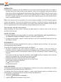
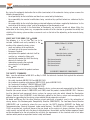
Good Morning Cardin
_
Installation guide
for automatic closing systems 2013
This digital palm device for measuring static and dynamic force, sums up and personifies our know how, and
our desire to be better. The device confers the secure knowledge that every installation has been carried
out in conformity with the European standards UNI EN12453 and UNI EN12445. Great force under control with
feather light precision.
WWW.CARDIN.IT
INDEX
INTRODUCTION AND AIM OF THE GUIDE
RESPONSIBILITY AND LEGAL OBLIGATIONS
WHAT HAS TO BE DONE: THE TECHNICAL FILE
- RISK ANALYSIS
- LIST OF COMPONENTS
- MAINTENANCE REGISTER
WHAT HAS TO BE DONE: THE CONFORMITY DECLARATION
4
4-5
5-7
7-8
8
8-9
WHAT HAS TO BE DONE: MARKING WITH THE SYMBOL
THE SAFETY STANDARDS
- THE NEW SAFETY STANDARDS
- THE EN12453 STANDARD – REQUIREMENTS
MINIMUM PROTECTION LEVEL
FORCE LIMITATION
MOTION SENSORS AND SAFETY DEVICES
THE EN12445 STANDARD - TESTING METHODS
9-10
10-11
11
12
ATTACHED FORMS
RISK ANALYSIS
MAINTENANCE REGISTER
THE CONFORMITY DECLARATION
MAINTENANCE CONTRACT
GUARANTEE CONDITIONS
14-15
16-17
18
19-20
19-20
Conforms to UNI EN 12453 and UNI EN 12445
4
|
I N S TA L L AT I O N G U I D E
INTRODUCTION
The declaration of conformity, that the installer fills out and leaves with the end user after he has added an
automatic device to an already existing manual apparatus, attests that the automatic closing device conforms
to the relevant directive (in particular the Construction Products Directive 89/106/CE and to the current version
of the machine directive 2006/42/CE) as well as to the European technical standards, above all the standard
EN 13241-1 regarding industrial and commercial closing devices operating garages and gates whether they are
manual, motorized or automatic.
Note: all the directives that are mentioned in this manual have been accepted in Italy with Presidential approval
or other legal apparatus. The aim of these directives and standards is to define the technical, constructive and
operative characteristics and the testing methods for the devices which make up the automatic system and that
act as a safeguard against risks which could occur during the operative life of the system.
They therefore deal with safety aspects
Before confronting the purely technical standards we would remind the installer of what he must do to be
considered ‘within the rules’.
AIM OF THIS GUIDE
1. To supply fundamental information regarding the regulations, legal obligations and responsibility for a
safe automatic closing installation for domestic, industrial or commercial use;
2. To supply concrete technical support to simplify and directly satisfy all the requirements foreseen by the laws
and reference standards.
RESPONSIBILITY
The law states that the person responsible for the safety of an automatic closing installation is the same person
who carried out the initial installation.
The installer has the complete responsibility regarding the following:
• the correct installation of the system carried out according to the standards in force and following the
installation instructions supplied by the constructor of the component parts of the automatic closing installation;
• the use of approved materials (certified) which conform to the laws and reference standards covered by the
trademark.
To this end the installer must attach the certificates and/or the declaration of conformity to the instruction
manual of the component parts of the automatic closing installation.
• handing over documents to the client which contain the following:
- the operating instructions and warnings for the safe use of the system;
- normal periodic maintenance instructions;
- the declaration of approval;
- the maintenance register.
LEGAL OBLIGATIONS
The European community commission has declared that all automatic closing systems (motorised gates and doors
etc.) are governed by the Machine Directives (2006/42/CE) (1).
This directive states that the installer who "motorises" a gate or a door (therefore creating an installation) has the
same obligations as the constructor of an automatic machine and therefore must:
1. prepare the technical file;
2. fill out the declaration of conformity (2);
3. apply the symbol to the automatic closing system.
I N S TA L L AT I O N G U I D E
|
5
Note (1)
• already in the earlier version of the machine directive (89/392/CEE) adding automation to a new manual closing system made it a machine, and therefore the person who carries out the transformation must respect the
machine directives;
• the definition of a 'machine' according to the Machine Directive 2006/42/CE:
- an assembly, fitted with or intended to be fitted with a drive system other than directly applied human or animal effort, consisting of linked parts or components, at least one of which moves, and which are joined together
for a specific application;
- an assembly referred to in the first indent, missing only the components to connect it on site or to sources of
energy and motion;
- an assembly referred to in the first and second indents, ready to be installed and able to function as it stands
only if mounted on a means of transport, or installed in a building or a structure;
- assembly of machinery referred to in the first, second and third indents or partly completed machinery (see
below) which, in order to achieve the same end, are arranged and controlled so that they function as an integral
whole;
- an assembly of linked parts or components, at least one of which moves and which are joined together, intended for lifting loads and whose only power source directly applied is human effort.
• Definition of ‘partly completed machinery’:
‘partly completed machinery’ means an assembly which is almost machinery but which cannot in itself perform
a specific application. A drive system is partly completed machinery. Partly completed machinery is only intended to be incorporated into or assembled with other machinery or other partly completed machinery or equipment, thereby forming machinery to which this Directive applies;
• two other EU directives, Electromagnetic compatibility (2004/108/EC) and low power devices (2006/95/EC),
indicate the guidelines for the minimum safety requirements of machinery that is already being used.
Note (2)
- The conformity of a product is declared according to a directive, which defines the essential requirements that
are to be respected. The technical standards are fundamental instruments for guaranteeing that the product
conforms to the essential requirements of the directive.
By affixing or having affixed the marking, the manufacturer indicates that he takes responsibility for the conformity of the product and declares that it conforms to the essential requirements of all the directives effecting
that product and that correct procedures for evaluating the conformity of the product have been carried out.
WHAT HAS TO BE DONE: THE TECHNICAL FILE
The automatic closing system technical file that the installer has to fill out and save must contain the following
indications:
• complete mechanical and electrical drawings;
• risk analysis of the closing system and the solutions used;
• the technical manuals for each single component (with installation and maintenance methods and details);
• the list of components used (with their declaration of conformity (3) and the declaration of incorporation of the
party completed machinery);
• the operating instructions and general warnings for a safe installation are to be given to the end user;
• the maintenance register for the system is to be given to the end user;
• the declaration of conformity with the Machine Directive for the system is to be given to the end user.
Note (3)
In the declaration of conformity / incorporation you must indicate the directives to which the product conforms (see
also note 2) and the technical reference standards used for its construction.
6
|
I N S TA L L AT I O N G U I D E
RISK ANALYSIS
Possible risks, which can appear when using an automatic closing system and the solutions used to reduce or
eliminate them, are listed in the attached sheets.
To carry out correct risk analysis the following points should also be considered.
• check the constructive and mechanical condition of the closing system that is to be automated (door, gate,
etc.) and coordinate any eventual interventions required to obtain the correct and regular operation of the
closing device working manually;
• evaluate the risk level presented by the closing device remembering that different levels of risk can
be assigned to the same danger point); risk is in fact the combination of the probability which occurs in
dangerous situations (which increases with the number of users) with the graveness of the consequences;
• typical dangers associated with automatic closing are:
Bangs
Crushing
Shearing
Wedging
Dragging
Cuts
Hooking
COMPONENT LIST
Made up of a list of components and accessories used to carry out the automatic closing installation.
The technical characteristics and the installation, use and maintenance instructions for the products can be
found in their relative documentation supplied by the manufacturer of the product/s.
MAINTENANCE REGISTER
The maintenance register (as well as indications relating to the client, the closing system and the installer, the
list of components used and the residual risk indications) contains a a list of installation activity, maintenance
interventions repairs and modifications carried out throughout its lifetime; it must be available for inspection
by authorized bodies where required.
The new harmonized standards highlight the fact that maintenance is of fundamental importance in ensuring
that the automatic closing system remains efficient, without undesired blocks and guarantees its safety (4).
During maintenance interventions (5) all necessary actions must be taken to check that the closing system
corresponds to the operational and safety conditions at the time of the initial installation; the following must be
checked for example:
• limits of force must be respected if the safety of the automatic closing system is guaranteed by a torque
system (see standards EN12453 and EN12445);
• detection devices with direct safety functions, type E, or only courtesy functions, type D, must function
correctly (see standard EN12445).
rawing number
: DM0672
Note (4)
Maintenance
obligations
roduct Code
: Normative
Description :
ANALISI DEI RISCHI
Law decree 81/2008 – entirely dedicated to safety aspects – refers to maintenance as a general safeguard;
18-05-02
raft : P.J.Heath
Article 15 ofDate
the :decree
imposes the “regular maintenance of equipment, machinery and installations”.
ARDIN ELETTRONICA S.p.A - 31020 San Vendemiano (TV) Italy - via Raffaello, 36 Tel: 0438/401818 Fax: 0438/401831
I N S TA L L AT I O N G U I D E
|
7
Note (5)
The maintenance technician must carry out periodic maintenance interventions not only respecting the
indications of the various constructors of the installed components (regarding both the time of the intervention
as well as the frequency of intervention to be carried out) but also respecting the indications noticed by the
installer himself (in fact the installer is aware of where the installation is located, the ambient conditions and
what it is being used for).
It is evident that a maintenance contract must be stipulated containing at least the following:
• the personal Date of the contractor and the client;
• the binding period, prices, payment methods and eventual renewal terms;
• the frequency of ordinary maintenance interventions;
• the operations / checks that are carried out on the installation (meaning the closing system and its inherent
components) during periodic maintenance interventions;
• the methods to be followed when replacing components (due to failure or wear);
• the intervention management method (on call or extraordinary maintenance interventions)";
Notes:
as a follow up to the Directive 99/44/CE coming into force which regulates the relationship between the seller
and the customer regarding the “conformity and guarantee of consumer goods” (relationships between the
professionals, meaning the manufacturer of the product, the dealer and the installer are therefore excluded),
the installation is now considered a product in the category of consumer goods and is therefore subject to the
enacted laws of that directive. The installer is responsible and therefore must answer to the client (for two years
from the supply of the closing system) not only for the conformity of the installation (i.e. for having carried out a
competent installation and for having respected the installation instructions) but also for the conformity of the
products used in the construction of the automatic closing system.
He could claim from the constructors of the products for the used parts remembering however that:
• the duration of the guarantee may also be limited by the maximum number of manoeuvres that can be
carried out without maintenance interventions (as stipulated by the constructor and laid out in the instruction
manual);
• generally the guarantee is not valid in cases of product non-conformity owning to situations where
constructive defects cannot be held responsible. In the articles of titles I, II and III of Part IV ‘security and
quality’ of the consumer protection code, Law decree 6 September 2005 nr. 206 there are important indications
regarding product safety, faults and conformity guarantee of consumer goods.
WHAT HAS TO BE DONE: THE DECLARATION OF CONFORMITY
The conformity declaration, meaning the conformity of the complete installation, and the procedures used
by which the “constructor” (in this case the installer who assembles the automatic closing system) declares
that the “machine” respects all the essential safety requirements, which effect it and that it has been installed
correctly according to the standards and regulations in vigour.
Signing the conformity declaration authorises the “constructor” (in this case the installer) to attach the
mark to the machine.
The directives, which must be indicated in the declaration, are as follows:
• Machine directive – version 2006/42/CE;
• Electromagnetic compatibility directive (EMC) – version 2004/108/CE;
- Construction products directive (CPD) – version 89/106/CEE;
- And if required, the Radio and Telecommunications Terminal Equipment directive (R&TTE) – version 99/05/
CE.
Conforming with the above mentioned directives does not exclude the obligation to conform with other technical
standards and local laws e.g. the Directive 99/05/CE – regarding radio devices and telecommunications
terminals – and law decree 37 dated January 22nd 2008, the new 46/90).
8
|
I N S TA L L AT I O N G U I D E
By signing the conformity declaration the installer (constructor) of the automatic closing system assumes the
following responsibilities:
- the responsibility for the installation and how it was carried out by the declarer;
- the responsibility for eventual modifications being carried out by qualified technicians authorised by the
declarer;
- the responsibility for the installation being maintained following indications supplied by the declarer “as the
constructor of the closing system” and by the producers of the components used.
You are advised to include in the Declaration of Conformity any activities carried out before fitting the
automation to the closing device e.g. any operation carried out to the structure to guarantee the solidity and
stability of the closing system or other assessments such as the lack of the marking on the manual closing
system etc.
WHAT HAS TO BE DONE: THE MARK
The following is a list of Date that has to be
included (indelible and easily readable) in the
marking of the automatic closing system:
- name and address of the constructor
- last two digits of the year of construction
- European standards
- description of the product and what it will be
used for (e.g. automatic sliding gate)
- identification number that links the closing
device to its technical file
- information regarding the regulated
characteristics of the product
- the mark
- the directives to which the product conforms
AAAAA, PO Box 21, B-1050
01
EN 13241 – 1
Automatic closing system
Identification number
Resistance to water
Resistance to wind
Resistance to heat
Resistance to air
npd
2
npd
npd
(89/106/CEE; 2006/42/CE; 2004/108/CE)
THE SAFETY STANDARDS
Note: since the withdrawal of UNI 8612 on May 1st 2001 the technical standards that regulate the automatic
closing device sector are:
- the safety standards UNI EN 12453 and UNI EN 12445
- the standards regarding safety devices UNI EN 12978 (part of UNI EN 12453)
- the “mechanical standards” UNI EN 12604 and 12605
- the standards for installation and use UNI EN 12635
The legal references regarding the finished automatic closing system were only represented by the Machine
Directive (the current version is 2006/42/CE) until 2005, when the product standard UNI EN 13241-1 became
legal for industrial and commercial closing systems for garages and gates which allowed the Construction
Products Directive (the 89/106/CEE) to be effectively applied to the closing system and consequently the
obligation for marking for the closing system whether they be automatic or manual.
We would remind you that the other directives aimed specifically at products used in the automation of
closing devices: the Electromagnetic Compatibility Directive (2004/108/CE), The Low Power Device Directive
(2006/95/CE) and in particular, where the case may be, the R&TTE directive (99/05/CE) for Radio and
Telecommunications Terminal Equipment (radio control devices). The UNI EN 12453 standards and UNI EN
12445 are particularly significant because they are based on the analysis of danger situations; they cover
safety aspects and are laid out in the form of safety objectives; the methods and the solutions proposed should
not be considered to be the only method for satisfying the requirements of the standards and in fact other
solutions which provide an equivalent level of safety are allowed.
I N S TA L L AT I O N G U I D E
|
9
Note:
effectively reaching the safety objectives using different solutions from those indicated by the UNI EN 12453
will allow you to compile the Conformity Declaration; in this case however there is even greater reason for you to
indicate the solutions used to eliminate and/or reduce the risks in the technical file to clearly indicate that the
objectives have been reached.
THE EN12453 STANDARD – REQUIREMENTS
If we start from the principal that when a closing system is automated it automatically becomes a machine, the
EN12453 deals with the closing system safety problems as if it were dealing with a typical machine, that is to
say it begins with risk analysis; the next step is to put these measures into force in order to eliminate or reduce
as much as possible the risk level associated with the danger situations that have been detected.
This can be obtained through the following concepts:
- minimum protection level;
- force limitation;
- presence detection and safety devices.
It is important to remember that different risk levels can be associated with one single danger situation (risk
in fact is the combination of the probability that the danger situation will arise and the graveness of the
consequences). It is evident for example that the risk level rises:
- when the closing system is used by a great number of people;
- when those people cannot be trained;
- when it is not possible to limit the use of the closing system to an authorised group of people.
The standard EN12453 takes all this into account when defining the safety measures that should be adopted
depending on the outcome of the risk analysis.
MINIMUM PROTECTION LEVEL
The minimum protection level required by the standard for the main edge of the closing system depending on
the command type and the use of the closing system is laid out in the following table taking into account that:
• The types of use of the closing system are divided into three groups:
1) A limited number of people are authorised to use the closing system and it is not in a public area. Typical
examples are closing devices within apartment blocks (excluding doors that open on to public streets), the
use of which has been taught to the users.
2) A limited number of people are authorised to use the closing system and it is in a public area. (external area
of apartment blocks and on company premises).
3) Any person can use the closing system and it is situated in a public area.
• The letters A, B, C, D, E indicate the type of protection that is to be used:
A: Manual command button (i.e. manually held down);
B : Manual command using a selector switch to impede use by non-authorised persons;
C : Force limitation;
D : Obstacle or person detection device; they can be applied to either side or to both sides of the door (for
example photoelectric cells);
E : Presence detection devices that are designed and installed in such a way that under no circumstances can
a person be touched by the gate or door in movement (no contact detection devices). Typical examples are
pressure mats or photoelectric beams. These detection devices must cover the entire danger area.
10
|
I N S TA L L AT I O N G U I D E
Note:
The danger area is defined as the volume containing the gate or door in any position it can reach during
movement increased by the safety distance “d” in all directions and up to a height of 2,5 metres. The safety
distance “d” depends on the speed of the gate/door; it must not however be inferior to 200 mm but, if the closing
speed of the gate/door is greater or equal to 0,5 m/s, “d” must be at least 900 mm.
TYPE OF
ACTIVATION OF THEUSE OF THE CLOSING SYSTEM
CLOSING SYSTEM
Expert personExpert personUnlimited use
Command
(outside a public area)
(public area)
(public area)
Group 1Group 2Group 3
using a hold down
using a key and holding
Manual
button (A)
it in position (B)
Impulse commands with the
force limitation (C) a
force limitation (C) /
force limitation (C) /
closing system in sight
photoelectric cells (D) /
or a safety device (E)
or a safety device (E)
(infrared command)
safety device (E)
Impulse commands with the
force limitation (C) /
closing system not in sight
or a safety device (E)
(radio controls)
Automatic
force limitation (C) and
photoelectric cells (D) /
safety device (E)
force limitation (C) and
photoelectric cells (D) /
safety device E)
force limitation (C) and
photoelectric cells (D) /
safety device (E)
force limitation (C) and
photoelectric cells (D) /
safety device (E)
force limitation (C) and
photoelectric cells (D) /
safety device (E)
FORCE LIMITATION
The force limitation of gate/door opening or closing is a typical aspect of the standards; the drawing below shows
the profile of the impact force detected on the main edge of the closing system using the instrument indicated by
the standard EN12445, which also indicates the points of measurement and how they should be carried out.
Dynamic force
Static force
Fd
1400N
gate/door force measured
over time
400N
Fs
150N
25N
T0
Td
Ts
time
There are four significant parameters:
• Dynamic force Fd, i.e. the surge of the profile of the detected force must be less than the value shown in the
underlying table (depending on the type of closing system and the passage opening);
I N S TA L L AT I O N G U I D E
|
11
• dynamic time Td must be inferior to 750 ms; Td represents the time during which the measured force exceeds
150 N (the normal translation force value);
• static force Fs, i.e. the force that remains after the dynamic time Td,, it must not however be greater than 150 N;
• final force Fe, i.e. the force that remains 5 seconds after the start of the measurement (Td + Ts), it must not be
greater than 25 N.
BETWEEN CLOSING BORDERS AND OPPOSITE BORDERSBETWEEN FLAT AREAS
PERMITTED surface area > 0,1m2
openings
of
openings
of
SURGE
FORCE
and sides ≥ 100 mm
50 to 500 mm
>500 mm
Closing systems with
horizontal (sliding) movement
400N
1400N
1400N
400N
1400N
1400N
Closing systems with vertical
movement (fold-up doors)
400N
400N
1400N
Closing systems rotating on an
axis parallel to the pavement
(garage doors/road barriers)
400N 400N1400N
Closing systems rotating on
an axis perpendicular to the
pavement (hinged doors)
PRESENCE DETECTION AND SAFETY DEVICES
Presence detection and “safety devices” regard closing systems where the safety is delegated to force limitation;
the classic photocells with one or two modulated beams are relegated to a secondary or courtesy form (type D
devices) according to the standard EN 12453, as they avoid people from being hit by the gate/door if they interrupt
the beam but are not considered safety devices (guaranteed by force limitation).
When the detection devices have a true safety function in the sense that the safety of the system depends
entirely on their correct operation, they are considered to be type “E” safety devices and it is evident that their
characteristics and the severity of the test they will undergo to check the conformity is definitely going to be greater
than the tests for type “D” devices.
As well as this the devices that carry out safety functions must satisfy the “resistance to failure” (UNI EN 12978)
requirements and the presence detection area must encompass the entire danger zone. The standard EN12453
obliges you to avoid danger situations caused by single failures both when the safety is guaranteed by force
limitation (case C) as well as when you are using presence detection (case E).
You obviously need to take into account that the failure you could occur both in the sensitive element itself (e.g. a
pressure contact safety edge or a photoelectric beam) as well as in the signal’s control circuit (from the sensitive
device to the ECU that controls the movement of the gate/door).
It is possible to make sure that a single failure does not reduce the safety level of the system in two ways:
• By duplication of the parts that are open to failure so making sure that the security function remains active
even in case of failure;
• By periodically monitoring the correct operation of the safety devices.
The standard requires that safety function test be carried out before the gate/door starts moving or a later during
the final movement of the device and if a failure is detected any movement of the gate/door must be inhibited.
12
|
I N S TA L L AT I O N G U I D E
The safety device are covered by the standard EN12978, regarding the functions of pressure sensitive devices
(e.g. sensitive edges or sensitive mats) or electro-sensitive devices (e.g. infrared devices such as the classical
photoelectric cells) and refer to UNI EN ISO 13849-1 (the new UNI EN 954-1).
THE STANDARD EN12445 – TEST METHODS
• The indications regarding how to measure force: where they should be carried out and the characteristics of
the measurement instruments (three measurements must be made at each point; the average value must
satisfy the requirements);
• The procedure and the methods for checking the correct position of type “D” and “E” presence detectors and
verifying their correct functioning is established by the use of witness objects (two types) that represent the
human body:
- Calibre A: a rigid parallelepiped 70 cm x 30 cm x 20 cm;
- Calibre B: a rigid cylinder length 30 cm and diameter 5 cm.
For closing systems fitted with one or more type “D” detectors the standards only require checks made with
calibre “A”.
To check the efficiency of a type “E” detection device both of the calibres (“A” and “B”) must be used. The test
details depend on the type of closing system but the gate/door must stop moving or invert its sense of travel
direction (avoiding danger situations) without the gate/door and the calibre coming into contact. The detection
area of the device must cover the entire danger zone of the closing device.
I N S TA L L AT I O N G U I D E
Regulations make us stronger.
And safer.
_
When a gate closes, a new chapter opens.
Dedicated to safety. It is in fact,
only after all the checks and measurements have been
carried out, that the work is deemed complete and the
Cardin product can take its place in the world.
Knowing that it is built to be safe brings a certain pride.
This is the prize that awaits us after every installation.
|
13
Installation / maintenance / assistance company:
RISK ANALYSIS
The dangers/risks indicated below are those most commonly found in automatic closing installations; it is therefore necessary to take into consideration additional dangers/risks that could occur
in specific situations and to exclude those which are not applicable. The dangers/risks that have been detected and which do not appear below must be added to this document or included in an
annex to this document along with the solutions used to resolve the situations.
Types of risk
(Mark the risks considered)
Evaluation criteria and solutions used
(tick the box corresponding to the solution used)
Mechanical and structural risks and wear and tear
loss of stability
The robustness of the structure has been checked, suitable materials and fastenings have been used.
falling parts
Required interventions and adjustments have been carried out to make sure the gate leaves cannot fall.
protrusions
Checked that protrusions greater than 4 mm (e.g.. the gate runner guide) have been rounded and
highlighted.
slippery surfaces
Checked that protrusions do not have slippery surfaces or could become slippery when it rains.
Checked the presence and efficiency of an anti-falling system for the moving parts.
Suitable travel limits have been installed and checked.
The necessary maintenance instructions have been supplied.
Further checks
The moving parts have been fitted with
enough protection according to the
standards in force and have been installed
following the manufacturer’s instructions.
If required and according to the manufacturer’s instructions, the speed adjustment of the gate leaf can
only be carried out by specialised personnel.
The gate has been fitted with a release device
to allow manual operation.
The opening has been checked to verify that there are no assembly errors.
Suitable instructions have been supplied to
carry out the manual release.
Suitable instructions explaining how to avoid unforeseen or non wanted start ups (e.g. during maintenance
interventions) have been supplied.
Risks caused by movement of the closing system
Risk type
A) bangs/ crushing
D) dragging / wedging
B) cuts
E) shearing
C) lifting
F) hooking
Solutions adopted
Protection to be applied
1) manual commands
8) multiplex barriers
(protective devices)
2) safety edges
(protective devices)
3) photoelectric cells
(detection devices)
9) acoustic signals
4) safety devices
11) warning signs
5) torque adjustment
(protective devices)
12) separation (using covers or
rubber buffers)
6) rounding the surfaces
13) wire mesh protection
7) safety mats
(protective devices)
14) other
10) warning lights
The forms are supplied by Cardin Elettronica S.p.A to facilitate the fulfilment of the obligations required by law and the company does not except any responsibility for incorrect, incomplete or erroneous compilation.
Installation / maintenance / assistance company:
RISK ANALYSIS
Safety and reliability of the operator and the command devices
safety conditions (even during failure and
blackouts).
Suitable command, movement and safety devices have been used which conform to the standard EN12453 (chapter 5
and appendix A).
Command devices fitted with buffer batteries which conform to the standards and regulations in force have been installed.
The installation has been carried out following the indications in the installation manual.
assembly errors and command coherence
command devices
The commands are coherent with the movement of the closing automation and with the instructions supplied by
the constructor.
An emergency stop device has been installed (and doesn’t introduce added risk).
The command devices have been installed in a visible and easily accessible position.
measuring the force of the closing device
Measurements have been carried out using instruments according to the standard EN 12445 and at the correct
points (chapter 5).
proximity protection devices (contact
between the closing system and people
must never be allowed)
A detection device which confirms to the standard EN 12978 has been installed.
detection devices
Checks have been carried out to the detection device according to the standard EN 12445.
Principles for integrating safety devices and information
residual non protected risks
The user has been informed that residual non protected risks remain and that foreseeable incorrect use of the
installation has been communicated.
warning devices
Warning lights, traffic lights and sirens etc. have been installed in correct and easily visible positions.
warning signs
Warning signs indicating residual risk have been positioned.
marking
An adhesive or plaque with the CE marking and containing the constructor’s Date, the address, series, type of
closing device and the installation year has been fitted.
User manual and safety instructions have been given to the end user.
user instructions
Keys and tools for manual release etc. have been supplied.
The commands have been situated in easily accessible positions.
Electrical risks
direct and indirect contact
Components marked with the CE symbol according to the Low Voltage Directive (2006/95/EC).
electrical energy dispersion
The electrical connection and connection to the mains conforms to the standards in force and is in agreement
with the instructions supplied by the constructor.
Electromagnetic compatibility risks
Approved radio control devices or those conforming to the directive R&TTE (99/5/CE) with allowed frequencies,
according to the relative standards, have been used.
electrical, magnetic and electromagnetic
field emission
Components marked with the CE symbol according to the EMC (2004/108/CE) directive have been used.
The installation follows the instruction manual for the operating device and for other eventual electrical and
electronic components.
Ergonomic risks
force required for manual movement
Check that the manual movement commands do not require excessive force and conform to the standard
EN12604 (manual gate opening/closing using force not greater than 150N if in a residential area or 260N if in a
commercial/industrial area) and to the standard EN12453 chapter 5.3.5.
Maintenance
how to proceed
A maintenance plan has been drawn up and put into act for the required time period (at least once every 6
months) maintenance contract.
power supply cut off devices
A cut off device has been installed to interrupt the electrical power supply.
documentation
Maintenance interventions have been registered and the CE declaration of conformity has been given to the end user.
The forms are supplied by Cardin Elettronica S.p.A to facilitate the fulfilment of the obligations required by law and the company does not except any responsibility for incorrect, incomplete or erroneous compilation.
Installation / maintenance / assistance company:
MAINTENANCE REGISTER
The following maintenance register contains the technical references, installation, maintenance, repair and modifications carried out, and must be made available
for inspection by authorised bodies where required.
Client:
(Name, address and reference person)
Description of the gate/door closing device:
(Model, type)
Identification number:
Location:
Gates/doors:
Power supply:
Installer:
(Address)
(Number, material, dimensions, weight)
Operating type:
(Voltage and electrical input)
(Name, address, telephone)
(Manual, semi-automatic, automatic)
Installation date:
List of installed components (drive unit, command and safety devices)
The technical characteristics and performance of the below mentioned components has been laid out in their relative installation manuals and/or on the technical Date plate.
Drive unit:
Motor:
ECU:
Photocells:
Safety devices:
Warning lights:
Radio controls:
Command device:
Other:
(Type)
(Serial number)
(Type)
(Serial number)
(Type)
(Serial number)
(Type)
(Serial number)
(Type)
(Serial number)
(Type)
(Serial number)
(Type)
(Serial number)
(Type)
(Serial number)
(Type)
(Serial number)
Indications regarding residual risk factors and foreseen improper use
Warning signs placed at the points of risk of the system and/or written indications explaining the risk factors and improper use should be given to the user of the gate
End user’s signature
Installer’s signature
The forms are supplied by Cardin Elettronica S.p.A to facilitate the fulfilment of the obligations required by law and the company does not except any responsibility for incorrect, incomplete or erroneous compilation.
MAINTENANCE REGISTER
Date:
Technician’s signature :
End user’s signature :
Technician’s signature :
End user’s signature :
Technician’s signature :
End user’s signature :
Technician’s signature :
End user’s signature :
Technician’s signature :
End user’s signature :
Technician’s signature :
End user’s signature :
Intervention description:
Date:
Intervention description:
Date:
Intervention description:
Date:
Intervention description:
Date:
Intervention description:
Date:
Intervention description:
The forms are supplied by Cardin Elettronica S.p.A to facilitate the fulfilment of the obligations required by law and the company does not except any responsibility for incorrect, incomplete or erroneous compilation.
Installation / maintenance / assistance company:
CONFORMITY DECLARATION
The undersigned:
Name
Address
Manufacturer of the automatic closing system and person responsible for the start up of the system declares that the product:
Description
Type
Serial number
Location
conforms to the requirements of the following EC directives:
Construction Products Directive 89/106/EEC
Machine Directive 2006/42/EC
Electromagnetic compatibility Directive 2004/108/EC
R&TTE Directive 99/05/EC
I also declare that the harmonised standards and/or specific technical standards:
EN 12604: Industrial gates and doors, commercial and domestic - Mechanical aspects- Requirements and class
EN 12605: Industrial gates and doors, commercial and domestic - Mechanical aspects - Testing methods
EN 12453: Industrial gates and doors, commercial and domestic - Safety when using motorised doors - Requirements
EN 12445: Industrial gates and doors, commercial and domestic - Safety when using motorised doors - Testing methods
Attached: the technical file
Place
Date
The client (on receipt)
The declarant
The forms are supplied by Cardin Elettronica S.p.A to facilitate the fulfilment of the obligations required by law and the company does not except any responsibility for incorrect, incomplete or erroneous compilation.
Installation / maintenance / assistance company:
MAINTENANCE CONTRACT CLAUSES
OBJECTIVE: guarantee that the automatic opening system functions correctly and safely throughout time.
The following is a list of clauses that the you are advise to insert into the contract that the contractor (the installation/ maintenance company) offers to the client
1. Establish the frequency of the preventative maintenance interventions (every ____ months) and the number of “installations” (also establish the type of
installation);
2. Indicate what to do to replace defective components or components that do not guarantee the correct working order of the system (e.g. only the cost of the
replaced components will be charged and for labour costs you need to consult the prices in force (for the association of installers in your country) at the
moment of the intervention;
3. The same goes for repair work requested outside of the normal scheduled maintenance program (e.g. these requests will be considered outside of the
present contract and will be charged according to the prices established by the installer’s association in your country. For each intervention the contractor
will charge (other than the time taken according to the price lists mentioned above and the cost of the components) a default fee for the requested intervention fixed at Euro ______);
4. Establish the duration of the service offered (e.g. two years) and how to renew it (e.g. year by year by tacit agreement); also establish the method of giving
notice whereby one of the two parties may cancel the maintenance service;
5. Establish the fee (excluding VAT) and the payment method (e.g. once the intervention has been carried out or in advance) and if travel costs are included
or not (in this case make reference to the official tables establishing reimbursement for the number of kilometres travelled);
6. Eventual reasons why the contractor can consider the contract no longer valid and interrupt the service (e.g. in cases where the client has not paid for the
agreed services the contractor company can deem the contract to be null and void and therefore interrupt the service, also in cases where maintenance
interventions have been carried out by other companies which also leads to the renunciation of all responsibility);
7. Indicate that the contractor cannot be held responsible for installation defects or defective repair work arising from previous work carried out by other
parties (hidden defects);
8. Other conditions where the Contracting Company has been freed of all obligation to carry out maintenance services or to replace damaged parts as covered
by the special conditions in points 2 and 3 (e.g. in cases where the defect is due to accidents, negligence or incorrect use of the mechanisms or any other
defects deriving from: breakage, failure caused by vandalism, attempted burglary, atmospheric phenomena etc.);
9. Indicate for example that the maintenance contract does not include technical interventions sand replacement of broken parts due to failure caused by
the installation of additional devices or tampering caused by personal not authorized by the Contracting Company. Any eventual special servicing of the
automation will be estimated and billed separately from the ordinary maintenance work;
10. Attach the list of operations to be carried out during the foreseen maintenance operations to the programmed maintenance contract (see following page);
11. Complete the documentation with the Date, Location and signature of both the contractor and the client for example:
Location
Date
The client (on receipt)
The declarant
The forms are supplied by Cardin Elettronica S.p.A to facilitate the fulfilment of the obligations required by law and the company does not except any responsibility for incorrect, incomplete or erroneous compilation.
Installation / maintenance / assistance company:
PROGRAMMED MAINTENANCE
CHECKS:
General visual inspection
Check the stability of gates/doors
Check hinges / pivots
Check plates with guide rollers
Check sliding wheels
Check tightness of nuts and bolts
Check photocell activation/intervention
Check safety edges functioning
Check warning lights
Check torque limiters functioning
Check command functions
Check radio controls
Check movement chains
Check closing electric locks
Check the electrical connection
Check electronic control unit
Check mechanical attachments
Check for abnormal noise
Check manual release system
Lubricate pivots / articulations
Appliance’s state of cleanliness
Check for regular movement
Check when the control/work has been carried out (X)
NOTE:
REPLACED MATERIALS:
Sign on receipt (client)
SN0002. app 7 / 04/2013
Technician’s signature
The forms are supplied by Cardin Elettronica S.p.A to facilitate the fulfilment of the obligations required by law and the company does not except any responsibility for incorrect, incomplete or erroneous compilation.
Installation / maintenance / assistance company:
GUARANTEE CONDITIONS
Foreword: in the following text CARDIN ELETTRONICA S.p.A. is indicated as "CARDIN" and the purchaser is indicated with the word "CUSTOMER". The
CUSTOMER of CARDIN is a retailer who buys materials for his professional activity. The guarantee conditions, between Cardin and the customer, are
therefore not governed by the law decree 24 of the 2/2/2002 (brought into force in Italy by the European directive 99/44/CE, regarding the conformity
of consumer goods) that defines the guarantee conditions between the last salesperson and the private customer.
Guarantee: all the appliances in the CARDIN price list are carefully controlled and tested and are guaranteed against manufacturing defects
(construction and performance) for a period of 24 months from the date they were manufactured; this limit is bound by the correct and periodic
maintenance of the system. The guarantee is also limited by the maximum number of manoeuvres that can be carried out by the product: 50.000
work cycles. Once the maximum period of 24 months has elapsed the guarantee becomes automatically void even if the maximum number of work
cycles has not been reached. The CUSTOMER must examine the goods, or have them examined, when they are received. This guarantee exclusively
covers construction anomalies caused by material defects that have been verified by the manufacturer.
It does not cover the following:
- damage caused by accidents, violent impact, manipulation negligence, incorrect installation and the use of non original CARDIN accessories or
spare parts and incorrect use of the product;
- damage caused by lightning, pools of water, seaquakes, fire, corrosive liquids, vandalism and war, incorrect power supply, positioning that does
not respect the installation plans supplied by the manufacturer, insufficient aerification and other causes deemed to be out of the control of the
manufacturer;
- products that have been tampered with or where identification plates, adhesives or seals have been rendered illegible or removed or the loosening
of fastenings defined as inaccessible by the technical manual;
- periodic controls, normal and extraordinary maintenance, settings, software upgrades, conversion, replacement of parts which undergo normal
wear and tear and breakage.
- consumables (lubricants, balancing springs, mechanical brakes);
- secondary power supplies (batteries);
- barrier elements (booms).
This guarantee is valid for anybody who has entered into possession of this product legally following the normal distribution channels authorised by
the manufacturer. The responsibility of CARDIN cannot however exceed the original sales cost of the product. CARDIN refuses any responsibility for
any extraordinary damage or in direct causes and effects. Any eventual claim regarding errors in delivery must be brought to the attention of CARDIN
within eight days of receiving the goods. In the event of complaints about the quality of the goods, the CUSTOMER has to communicate them to
CARDIN in writing and by registered post within eight days of the discovery of the defect. The repair or the substitution free of charge of the products
under guarantee will be carried out ex-works and all the costs of transport and assembly of the product will be the responsibility of the CUSTOMER.
Along with the product that is to be repaired or replaced under guarantee the CUSTOMER must supply CARDIN with a copy of the declaration of
conformity, the maintenance register for the system (filled out correctly in all parts) and the product installation method used.
NOTE: take note that the person that installs the system by assembling the different components (even if they have been made by the same
manufacturer) has the same responsibility as the manufacturer of the machine. The guarantee becomes null and void whenever products, that are
deemed to be defective by the CUSTOMER but have not yet been examined by Cardin’s technicians, have been tampered with. The guarantee is also
not applied in cases of product misuse; non conformity owing to negligence, oversight during transport and use; an installation not carried out by
professional personnel or not following the proper procedure also renders the guarantee null and void. All in all the guarantee is null and void in cases
where product non conformity has arisen under circumstances that cannot by attributed to manufacturing defects and in no case can CARDIN be
considered responsible for damage or profit loss arising during the product guarantee period or successively
NOTE:
SN0002. app 8 / 04/2013
TO GUARANTEE AN EFFICIENT AND SAFE INSTALLATION CARDIN ELETTRONICA RECOMMEND, THE USE OF CARDIN APPLIANCES THAT HAVE BEEN TRIED
AND TESTED TO WORK TOGETHER IN SYNERGY UNDER ALL CONDITIONS.
THE DECLARATION OF CONFORMITY FOR ALL CARDIN APPLIANCES CAN BE DOWNLOADED FROM THE STANDARDS AND CERTIFICATION AREA OF THE
WEBSITE www.cardin.it.
IN SPECIFIC CASES THE CERTIFICATES CAN BE REQUESTED FROM OUR AUTHORISED DEALERS OR DIRECTLY FROM THE CARDIN STANDARDS AND
CERTIFICATION OFFICE.
The forms are supplied by Cardin Elettronica S.p.A to facilitate the fulfilment of the obligations required by law and the company does not except any responsibility for incorrect, incomplete or erroneous compilation.
22
NOTES
|
I N S TA L L AT I O N G U I D E
I N S TA L L AT I O N G U I D E
|
23
NOTES
CARDIN ELETTRONICA FRANCE
CARDIN ELETTRONICA BELGIUM
333, Avenue Marguerite Perey
77127 LIEUSAINT CEDEX
Tél: 01 60 60 39 34
Fax: 01 60 60 39 62
http:// www.cardin.fr
Acaciastraat 18B
B-2440 Geel
Tel: +32(0)14/368.368
Fax: +32(0)14/368.37
http:// www.cardin.be
Cardin Hotline France
Cardin Hotline Belgium
0892 68 67 07
014 368 368
CARDIN ELETTRONICA S.p.A
GRUPPO RIELLO ELETTRONICA
RIELLO ELETTRONICA
SN0002 - 04/2013
Via del lavoro, 73 – Z.I. Cimavilla
31013 Codognè (TV) Italy
GPS 45.864, 12.375
Tél: (+39) 04 38 40 40 11
fax: (+39) 04 38 40 18 31
e-mail (Italy): [email protected]
e-mail (Europe): [email protected]
http:// www.cardin.it