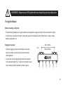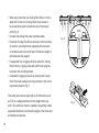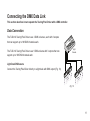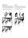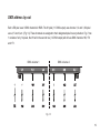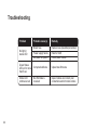
1
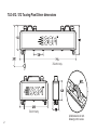
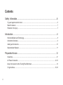
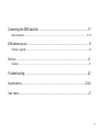
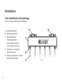
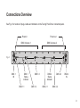
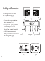
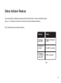
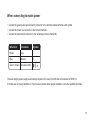
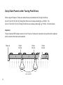
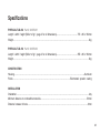
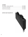
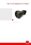
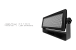
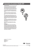
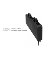
TLD·612 / 312
TOURING PIXEL DRIVER
TLD-612 / 312 Touring Pixel Driver dimensions
TLD-612 only
TLD-312 only
2
All dimensions in mm.
Drawing not to scale.
TLD·612 / 312 PIXEL DRIVER
USER MANUAL REV. 1
© 2010-2012 SGMTM. Information subject to change without notice. SGM and all affiliated
companies disclaim liability for any injury, damage, direct or indirect loss, consequential
or economic loss or any other loss occasioned by the use of, inability to use or reliance
on the information contained in this manual. The SGM logo, the SGM name and all other
trademarks in this document pertaining to services or products by SGM or its affiliates and
subsidiaries are trademarks owned or licensed by SGM or its affiliates or subsidiaries.
TLD-612/312 Pixel Driver uk
3
Contents
Safety Information....................................................................................................6
To guard against electric shock.........................................................................................................................6
Read the manual................................................................................................................................................7
Protection from injury.........................................................................................................................................7
Introduction.........................................................................................................................8
Parts Identification and Terminology...................................................................................................................8
Connections Overview........................................................................................................................................9
Cabling and Connectors...................................................................................................................................10
Status Indicator Readout...................................................................................................................................11
Preparation for use............................................................................................................12
Unpacking......................................................................................................................................................12
AC Power Connection.................................................................................................................................12-13
Daisy Chain power to other Touring Pixel Ball drivers......................................................................................14
To rig the fixture...........................................................................................................................................15-16
4
Connecting the DMX data link................................................................................17
Data Connection.........................................................................................................................................17-18
DMX address lay-out............................................................................................................19
Firmware upgrade...........................................................................................................................................20
Service.......................................................................................................................21
Cleaning........................................................................................................................................................21
Troubleshooting.....................................................................................................22
Specifications.......................................................................................................23-26
User notes...........................................................................................................................27
5
Safety Information
WARNING! Read the safety precautions in this section before
installing, powering, operating or servicing this product.
To guard against electric shock

DANGER! Risk of electric shock. Do not open cabinet.
• This product is for professional use only. It is not for household use.
• This product presents risks of severe injury or death due to fire hazards, electric shock and falls.
• Do not open the cabinet. No inside parts are user-serviceable.
• Always ground (earth) the system electrically.
• Use only a source of AC power that complies with local building and electrical codes and has both overload and earth leakage protection.
• Never attempt to bypass the fuse. Always have defective fuses replaced with ones of the specified type and rating.
• Verify that the power feed cable is rated for the total current draw of all daisy-chained products.

6
Read the manual
DANGER! Risk of electric shock. Do not open cabinet.
Read this manual before installing, powering or servicing the system, and follow the safety precautions.
Always observe all warnings in this manual and printed on the Touring Pixel Driver. If you have questions about
how to operate the system safely, please contact your SGM representative.
Protection from injury
• Ensure that any structure used for support as well as all fastening and connecting hardware can hold at least 10
times the weight of all supported devices and equipment.
• Use a minimum of two approved secondary attachments (such as safety wires) to secure each product as de-
scribed in this manual. Safety wires must be approved by an official body such as TÜV as a safety attachment for the total weight of the products it secures. Safety wires must be capable of supporting a static suspended
load of ten times the weight of the product.
• Check that all external covers and rigging hardware are securely fastened.
• Block access below the work area and work from a stable platform whenever installing, servicing or moving the product.
• NOTE: All illustrations in this manual pictures depict only the dual DMX universe TLD-612 system, but all terminology, connection lay-outs, power and data principles also apply to the single DMX universe TLD-312.

7
Introduction
Parts identification and terminology
See Fig. 1 for part terminology and identification.
A. Mounting bracket left
B. Mounting bracket right
C. Touring Pixel Driver /
Power supply cabinet.
(In this document referred
to as: TLD-612 & TLD-312).
D. Connections. (“Connections
Overview” page 10).
E. LED pixel outputs from 1 to 6 rows
(Illustrated by LED Balls)
8
Fig. 1
Connections Overview
See Fig. 2 for location of plugs, cables and indicators on the Touring Pixel Driver connection panel.
Power in
Power out
DMX Universe 1
DMX Universe 2
Fig. 2
DMX 1
IN
DMX 1
Status
indicator
DMX 1.1
DMX 1.3
DMX 1.2
DMX 2
Status
indicator
DMX 2.1
DMX 2.3
DMX 2
IN
DMX 2.2
9
Cabling and Connectors
The following connectors are used on
the Touring Pixel Driver (Fig. 3):
• 5 pin male XLR connector for data input.
(See pin assignments, Fig. 4)
• 3 lead power cable. A power plug must be
installed on the power input cable.
(See “AC Power Connection”, page 12-13)
• 6 x RJ765 output connectors supply
12VDC power and data to the LED products.
(See pin assignments, Fig. 5)
Fig. 3
5 pin XLR
4 pin Rj765
5 pin male XLR input connector
4 pin female RJ765 connector
Connector front shown
Connector front shown
Fig. 4
10
5 pin XLR male
Fig. 5
Status Indicator Readout
Two status indicator readouts are visible on the Pixel Pixel driver; one for each DMX universe.
(See p. 9, “Connections Overview” for location of the status indicator readouts).
Fig. 6 clarifies the status indicator readouts.
Indicator
Status
Continuous
green light
Waiting in bootloader
mode
Continuous
red light
No DMX is received
Continuous
red, flashing
yellow light
DMX is received
Fig. 6
11
Preparation for use
Unpacking
• Touring Pixel Driver
• User manual
The packing material protects the Touring Pixel Driver during shipment. Please save it for future transportation.
AC Power Connection
Connect the Touring Pixel Driver directly to AC power. Do not connect this product to a dimmer system
as it will damage the fixture.
The Touring Pixel Driver is delivered with a 0.6 meter power cable in both “Power in” and “Power out”. The “Power
out” connector is fitted with a CEE female mains connector for test and protection only. The customer must provide and install a connector that enables the Touring Pixel Driver to receive AC Mains Power.
Install a grounding-type (earthed) industrial 3-prong type B plug that complies with IEC 60309 or a comparable
national standard and is rated 16 A minimum, and use corresponding power outlet sockets. Follow the manufacturer’s instructions and all locally applicable laws and electrical safety codes.
12
When connecting to mains power
• Connect the green/yellow ground (earth) conductor to the terminal marked with the earth symbol.
• Connect the brown live conductor to the terminal marked L.
• Connect the blue neutral conductor to the remaining terminal (marked N).
Wire Color
Conductor
Symbol
Brown
Live
L
Blue
Neutral
N
Green / Yellow
Ground (earth)
The auto-ranging power supply automatically adjusts to AC power from 85-264 volts nominal at 50/60 Hz.
If the pins are not clearly identified, or if you have any doubts about proper installation, consult a qualified electrician.
13
Daisy Chain Power to other Touring Pixel Drivers
When using the Power-in / Power-out cables that are pre-installed in the Touring Pixel Driver:
Up to 8 TLD-612 (16 TLD-312) Touring Pixel Drivers can be daisy-chained @ e.g. 230VAC, 13A.
Up to 4 TLD-612 (8 TLD-312) Touring Pixel Drivers can be daisy-chained @ e.g. 115VAC, 13A. (Not shown)
Important
The pre-mounted CEE female connector on the “Power out” cable are for protection only and should be replaced
with a connector that meets local standards.
Power in
Power
link out
Power
link out
User installed
power connector
14
Power
link out
WARNING! Always secure LED system with secondary fixing such as safety wires
To rig the fixture
Before installing, verify that;
• The attachment hardware is in good condition and designed to support at least 10 times the fixture’s weight.
• The structure can support at least 10 times the weight of all installed Touring Pixel Drivers, clamps, cables,
auxiliary equipment, etc.
Rigging the system:
• Start the rigging process by blocking the work area
Min. 160mm
Fig. 7
Max. 500mm
below and make sure the work is performed from a
stable platform.
• Loosen the mounting brackets and slide the brackets
to the desired length (Fig. 7) and turn the thumb screws
fully clockwise until the bracket is locked in place.
15
•
•
•
•
•
When using more than one Touring Pixel Driver to form a wider LED curtain, the Touring Pixel Drivers needs to
be spaced 6mm apart to obtain the correct 12cm pixel pitch (Fig. 8).
Connect and arrange the power and data cables.
Fasten the Touring Pixel Driver securely to a fixed surface or structure, ensuring that the supporting structure and /
or hardware used can hold at least 10 times the weight of all the devices they support.
If suspended from a rigging structure, fasten the Touring Pixel Driver to a rigging clamp with a M10 bolt using the top hole in the mounting bracket.
Complete the rigging procedure by securing the Touring
6mm
Fig. 8
Pixel Driver with a safety wire using the hole in the mount-
ing bracket shown in Fig. 9
This safety wire must be approved by an official body such
as TÜV as a safety attachment for the weight that it supports. The safety wire must be capable of supporting a static
suspended load that is ten times the weight of the fixture and
all installed accessories.
16
Fig. 9
Connecting the DMX Data Link
This section describes how to operate the Touring Pixel Driver with a DMX controller.
Data Connection
The TLD-612 Touring Pixel Driver uses 2 DMX universes, each with 3 outputs
that can support up to 168 DMX channels each.

The TLD-312 Touring Pixel Driver uses 1 DMX universe with 3 outputs that can
support up to 168 DMX channels each.

Light Desk DMX source
Connect the Touring Pixel Driver directly to a light desk with DMX output (Fig. 10).
Light
Console
Fig. 10
17
Light Desk with ArtNet
Use a Light Desk or computer-based ArtNet controller
via an Ethernet switch and an Artnet to DMX converter
to control multible Touring Pixel Drivers. (Fig. 11)
Light Desk
DVI source
The Touring Pixel Driver can also connect to any DVI
source, e.g. media server or analog camcorders, via a
DVI / VGA to DMX converter. (Fig. 12)
DVI
Ethernet
Switch
Artnet to
DMX
converter
Video
Video
DVI / VGA to DMX
Converter
Fig. 12
Artnet to
DMX
converter
Fig. 11
18
DMX address lay-out
Each LED pixel uses 3 DMX channels for RGB. The #1 pixel (1.1 DMX output) uses channel 1, 2 and 3, #2 pixel
uses 4, 5 and 6, etc. (Fig. 14). These channels are assigned to their designated pixel in every situation. E.g. if row
1 consists of only 14 pixels, the #1 ball in the second row (1.2 DMX output) will still use DMX channels 169, 170
and 171.
DMX universe 1
DMX universe 2
Fig. 14
19
Firmware upgrade
Log on to www.sgmsupport.com to access all relevant firmware
and follow the instructions for download and installation.
20
Service
WARNING! Read the safety precautions in this section before
installing, powering, operating or servicing this product.
Fuse Replacement
The TLD-612/312 uses a time-delay fuse for protection against current overload. The fuse is located inside the
base on the main PCB of the fixture – next to the low voltage power supply. Fuses must be replaced by a certified
professional.
Cleaning
To obtain optimal performance, regular cleaning is essential. Cleaning schedules will vary greatly depending on
the operating environment, and the installation should therefore be checked at frequent intervals within the first
few weeks of operation to see whether cleaning is necessary. This procedure will allow you to assess cleaning
requirements in your particular situation. If in doubt, consult your SGM dealer for a suitable maintenance schedule. Clean the TLD-612/312 with a soft cloth dampened with a solution of water and a mild detergent. Do not
use products that contain solvents, abrasives or caustic agents for cleaning, as they can cause damage to both
hardware, cables and connectors.

21
Troubleshooting
22
Problem
Probable cause(s)
Remedy
No light in
status LED
Blown fuse
Power supply failure
No power to system
Replace fuse (Qualified personnel)
Refer to SGM
Check power cables
Green Status
LED on for more
than 5 sec.
Corrupted software
Upload new firmware
Status LED
continuous red
No DMX data is
received
Inspect cables and correct poor
connections and/or broken cables
Specifications
PHYSICAL TLD-612 Part #: 80070201
Length / width / height (Refer to fig.1, page 2 for all dimensions).............................................715 x 80 x 182mm
Weight..................................................................................................................................................................4kg
PHYSICAL TLD-312 Part #: 80070202
Length / width / height (Refer to fig.1, page 2 for all dimensions).............................................355 x 80 x 182mm
Weight..................................................................................................................................................................2kg
CONSTRUCTION
Housing.....................................................................................................................................................Aluminum
Finish.............................................................................................................................Electrostatic powder coating
INSTALLATION
Orientation............................................................................................................................................................Any
Minimum distance to combustible materials.....................................................................................................50mm
Distance between drivers...................................................................................................................................6mm
23
AMBIENT OPERATING CONDITIONS
Maximum ambient temperature (Ta)......................................................................................................40°C (104°F)
Minimum ambient temperature (Ta)........................................................................................................-10°C (14°F)
Operating humidity.............................................................................................................................................100%
IP rating..............................................................................................................................................................IP 55
SIGNAL SOURCE
According to standard......................................................................................................................USITT DMX 512
CONNECTIONS
AC Power input............................................................................................................................................CEE male
AC Power output.......................................................................................................................................CEE female
DMX Data input......................................................................................................Locking 5-pin XLR male sockets
Driver Data output.......................................................................................................Locking 4-pin RJ765 sockets
ELECTRICAL
AC power.....................................................................................................................................85 – 264V, 50/60Hz
Build in power supply - Daisy chainable
Maximum total power consumption, TLD-612...................................................................................................360W
Power consumption without load, TLD-612........................................................................................................14W
Maximum total power consumption, TLD-312...................................................................................................180W
Power consumption without load, TLD-312..........................................................................................................7W
24
TYPICAL POWER AND CURRENT
100V, 60Hz...............................................................................................................................346W,
120V, 60Hz...............................................................................................................................344W,
208V, 60Hz...............................................................................................................................335W,
230V, 50Hz...............................................................................................................................334W,
240V, 50Hz...............................................................................................................................334W,
Power factor is measured at full load with all LEDs 100% driven.
3,50A,
2.90A,
1.66A,
1.50A,
1.45A,
0.99PF
0.99PF
0.97PF
0.97PF
0.96PF
FUSES
Mainboard fuse (not user-replaceable)..........................................................................................................T12.5A
Power supply (not user-replaceable)...................................................................................................................F5A
APPROVALS
Safety.......................................................................................................................................................EN 60950-1
EMC..................................................................................................................................EN 55103-1 , EN 55103-2
INCLUDED PARTS
• Touring Pixel Driver TLD-612 / TLD-312
• User manual
25
ACCESSORIES
LB-100, LED Balls - 1 meter string containing 7 balls......................................................................Part # 80080001
LT-100, LED Tube 1 meter (27 pixels).............................................................................................Part # 80080003
LT-200, LED Tube 2 meter (54 pixels).............................................................................................Part # 80080004
Specifications subject to change without notice
26
User notes
27
SGM A/S · Soeren Frichs Vej 51-53 · DK 8230 Aabyhoej · Denmark
Tel +45 70 20 74 00 · [email protected] · www.sgmlight.com