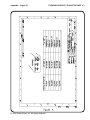
1
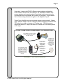
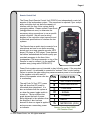
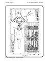
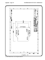
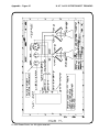
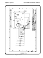
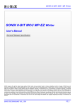
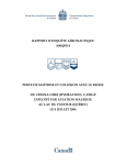
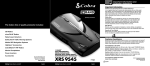
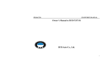
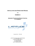
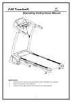
AERO VOICE™
AIRBORNE LOUDHAILER SYSTEMS
INSTALLATION & USER’S GUIDE
PSAIR12A
PSAIR22A
PSAIR42A
Power Sonix, Inc.
122 S. Church St., Martinsburg, WV 25401 USA
304-267-7560; Fax 304-268-8691
www.powersonix.com
TABLE OF CONTENTS
I.
Overview Of Aero Voice Public Address Systems
Page 1
Installation Considerations
II.
Installation Quick Start & Checklist
Page 2
Standard Cable Connections
Power For The Aero Voice System
DC Power From Aircraft Batteries
DC Power From Power Sonix 28 V Auxiliary Battery Pack
Audio Controller/Remote Control Unit
III.
Mounting The Amplified Speaker(s)
Page 6
PSAIR12
PSAIR22
PSAIR42
IV.
Using The Aero Voice System
Page 10
Using the Power Sonix Remote Control Unit
Interfacing With Cockpit Audio Controllers
Live Microphone
Pre-Recorded Messages, Tape/Digital Input
Standard Sirens
Custom Sirens/Sounds
V.
Maintenance
Page 13
Routine Audio Testing
Battery Maintenance & Charging
VI.
VII.
Technical Specifications
Limited 2-Year Warranty
RMAs
Power Sonix Support
Page 17
Page 18
VIII.
Appendix: Drawings & Illustrations
IX.
Your Dealer/Outfitter Info:
____________________________________________________
Dealer Sales Contact
Phone
____________________________________________________
Dealer Customer Service Contact
Phone
____________________________________________________
Outfitter/Installation Service Contact
Phone
304-267-7560
____________________________________________________
Power Sonix Factory Support/RMAs Contact
© 2006 Power Sonix, Inc. All rights reserved.
Page 1
I.
Overview Of Aero Voice Public Address Systems
Congratulations on your purchase of a Power Sonix public address system. Your
aircraft is about to be equipped with the best performing airborne speech
projection system in the world today. No other system is as light, as compact, as
intelligible, as powerful or as economical as Power Sonix.
The Power Sonix “A” series of Loudhailer Systems was specifically developed
for those who wish to recess their speakers and amplifiers inside the aircraft for
a flush mount. The PSAIR12A, PSAIR22A, AND PSAIR42A consist of a single,
high performance, class D amplifier, the PSAMP600, used to create a 300 or
600 watt system, and a PSAMP1200 for 1200 watts of power. The speaker kit,
PS-SPK-300, consists of a single horn assembly with two X 150 watt speaker
drivers for a total of 300 watts. To gain more powerful systems they are simply
paralleled to the amplifier used. This configuration is in contrast to the non-A
series that has the amplifier contained in the speaker chassis and can be
mounted internally if there is space, but is often mounted outside the aircraft.
Installation Considerations:
The first thing that must be determined is where you will place the speaker array
on your specific aircraft. Power Sonix recommends that the system be mounted
in such a way as to project sound down and away from the aircraft at an angle
that is consistent with the aircraft’s mission requirements. At an angle of 45
degrees with the vertical, the peak intensity of the sound beam will hit the
ground at a distance from the aircraft that is equal to the altitude of the aircraft.
The distance out from the aircraft of peak intensity is the product of the tangent
of the angle times the expected height of the aircraft during broadcast. Please
note that there are two engineering bracket drawings for a single and dual horn
in the Appendix, Figs. VII & VIII. These may be of some value in custom
designing a recessed mount.
Once placement has been determined, the next consideration is what will power
the PA system. Power can come from the DC voltage source on the
aircraft or a Power Sonix 28V auxiliary battery pack. Stand alone battery packs
have limited power and must be recharged. Consult with your dealer and
maintenance chief to determine which is best for your needs.
A 45° angle enables the pilot and/or observer to maintain visual contact with the
intended audience from a safe hovering position. Don’t be concerned with being
too far from your audience. Power Sonix systems have great range. If you are
close, you can always reduce the volume.
The third major consideration is interfacing the audio signal sources
with the Amplifier. You can use the cockpit headphone mic to deliver speech
© 2006 Power Sonix, Inc. All rights reserved.
Page 2
through the cockpit audio controller to the amplifier. This requires that the
cockpit audio controllers have an audio output for a PA system (many
commercial controllers like Technisonics, Garmin and NAT do). See the
operating manual of your controller to see how to integrate your existing
equipment with Power Sonix PA Systems. We have provided an NAT AA-22
type cockpit controller interface drawing for Power Sonix Loudhailers in the
Appendix, Fig.VI. Our engineering dept. is always available to help answer
questions regarding this procedure….please feel free to call to expedite your
installation.
Instead of the cockpit headphones, you can alternatively use a separate noise
cancelling microphone (Power Sonix part # PSMIC) and the Power Sonix
Remote Control Unit (PSRCU). The RCU is required in any instance where the
existing cockpit audio controller does not support a public address system. In
that case, it is the audio controller for the PA and has its own on/off switch.
The advantage to having the RCU, in addition to a supporting cockpit audio
controller, is the convenience to do things quickly and easily in the air including;
1.) having someone without a headset speak into the system with a hand-held
mic, 2.) the ability to plug a cassette tape, MP3 player, CD player or DVD
player with pre-recorded messages/sounds into the RCU which delivers the
digital signal to the amplified speaker array. If you intend to do these things with
your existing audio controller, make sure that it has the necessary wiring
interconnects available and consult your equipment user’s manual.
The finish on the Remote Control Unit is anodized black. The speaker
assemblies come standard in a powder-coated white or olive drab finish.
II.
Installation Quick Start: Standard Cable Connections
There are only a few connections that have to be made to make your Power
Sonix system operational. All the wiring is factory installed and tested.
Once the speaker mounting position is determined, measurements of the
distance from the speakers to the power source, the amplifier and to the audio
controller (either the cockpit audio controller or the Power Sonix Remote
Control Unit) are made. Appropriate connectors and cables cut to length must
be purchased separately to make the custom cables for your specific aircraft.
Please be sure you have made these measurements and placed the order for
these parts in advance of the installation date.
© 2006 Power Sonix, Inc. All rights reserved.
Page 3
Illustration 1 depicts the PSAIR A-Series system cabling configuration.
Each installer will make his own cables for the installation interface with
power, speakers and remote controls. Accordingly, mating connectors for
the amplifiers are not provided with System you purchase. A part number
list for these mating connectors is given in the Appendix; Fig. IX.
Power Sonix Amplifies are input protected against reverse polarity. Always
apply positive voltage to Pin A of the input power connector from the 28 Volt
DC power buss using a minimum of 16 gauge wire. 300 Watt systems
should be fused at 15 amps, 600 watts at 30 amps and 1200 watt systems
at 60 amps.
BASIC PSAIR SYSTEM COMPONENTS & CONNECTIONS
The amplifier connects to a power
supply, the speaker array and to
an audio controller.
The loudspeaker system
is controlled by either the
cockpit audio controller (if
capable), or by the Power
Sonix Remote Control
Unit (PSRCU) shown to
the right.
The mic in the
cockpit headset
can be used if
connecting to the
cockpit audio
controller. A
separate mic is
used when
connecting to the
Power Sonix
remote control
(PSRCU).
Illustration 1 - Basic System Connections
© 2006 Power Sonix, Inc. All rights reserved.
The REC input
connection on our
Remote allows
prerecorded
message to be
played from MP3,
cassette or CD
players.
Page 4
Power Connections For The Aero Voice System
The source power source MUST be 24-32 VDC (i.e. nominal 28 V aircraft
supply). NOTE: THESE SYSTEMS ARE NOT DESIGNED TO OPERATE
WITH MORE THAN 32 VOLTS.
Using AIRCRAFT DC POWER - As noted before, connectors and cable for
DC power must be ordered separately. Positive on pin A.
Using AUXILIARY BATTERY POWER - This requires a Power Sonix 28 Volt
NiCad battery pack (PSBAT28 or PSBAT28SCU) and Power Sonix power
cable PSCBL-BAT in the length appropriate for your aircraft.
Please consult with your dealer, outfitter and maintenance crew chief to
determine the power configuration that best meets your needs on your
aircraft. The current load of other aircraft equipment such as cameras and
searchlights, which might be used simultaneously with the Loud Hailer,
needs to be evaluated when using aircraft DC power. Please contact
Power Sonix Engineering. Dept. for any questions regarding any
installation issues.
© 2006 Power Sonix, Inc. All rights reserved.
Page 5
FAA Field Inspection
Once installed, an FAA Form 337 Field Test must be conducted to get your
modification approved. There is no cost from the FAA for this test. After you
schedule the inspection with your nearest FAA Field Office, you just have to
make the aircraft and a pilot available. This is standard procedure and any
FAA licensed maintenance or overhaul facility will take care of this for you.
(Note: Military and State and Local Government Law Enforcement agencies may
not be subject to the N Classification modification requirements of the FAA.
However, it is always a good practice to thoroughly test the aircraft after any
major modification, including the addition of externally mounted loudspeakers,
searchlights, cameras etc.).
Using the Power Sonix Aero Voice System
Operating the voice Amplifier system is relatively simple. However, certain
techniques, some of which will be gained by experience, should be developed
to obtain the most favorable results. The system possesses the capability of
high quality voice transmission over long distances and for long periods of
time. However, effective utilization of these features depends, to a great
extent, upon proper operating procedures.
To successfully project the voice over long distances, it is necessary to
develop a microphone technique different from the normal conversational
manner. Talk clearly and distinctly, separating each word with noticeable
pauses. Keep the voice volume high with the top of the microphone touching
the upper lip so that the speech is as close to the microphone as possible.
Words should be spoken with clear enunciation and a commanding voice for
maximum sound projection
Microphone Options And Operation
Users may utilize an existing cockpit headset microphone connected to a
cockpit audio controller provided that the controller has appropriate
connectors to receive the cable from the Power Sonix amplified speaker
assembly . Alternatively, users can employ the Power Sonix/Shure noisecancelling microphone (PSMIC) by connecting it to either a mic jack on the
cockpit audio controller or to the mic jack on the Power Sonix Remote Control
Unit (PSRCU). Always hold the PSMIC against the upper lip and speak
strongly in clear enunciation.
On the PSMIC, the "Gain" control is adjusted clockwise from OFF. If troubled
with feedback it may be necessary to reduce the input "Gain" control or
preferably, improve the sound shielding of the microphone position. This can
be done by closing windows and eliminating a direct audio air medium back to
the microphone from the speakers.
© 2006 Power Sonix, Inc. All rights reserved.
Page 6
Remote Control Unit
The Power Sonix Remote Control Unit (PSRCU) can independently control all
aspects of the loudspeaker system. This component is required if your cockpit
audio controller does not have the capacity to
interface with the Aero Voice system and its
connecting cables. Please contact Power Sonix
([email protected]) to determine the
necessary wiring connections to use a specific
cockpit controller. We will need a wiring
diagram of the controller output connector and
its electrical specifications to interface the two
systems.
The Remote has an audio input connector for a
microphone and one for an audio recording
devise such as a tape cassette recorder, MP3
player, CD player or DVD player. These devises
can deliver standardized and studio quality prerecorded messages to the Aero Voice
loudspeakers. The large connector on top of the
Remote is used to connect it to the amplified
speaker array (using cable PSCBL-RCU).
Power Sonix systems are not intended to play hi-fidelity music. If the recorded
sound is music, it is advisable to operate at a reduced "Gain" control setting.
Failure to reduce the gain setting may cause excessive power to be dissipated
in the speaker units and result in
failure of the speaker voice coils due
PIN
FUNCTION
to overheating.
The red Push-To-Test (PTT) power
light will show that DC power is
connected when depressed. It is
also an indicator that the system is
on when the power toggle switch is
turned on. The ten element bar
graph shows the level of power
being delivered to the speakers from
the amplifier. It also has one
element lit when no signal is applied
and serves as a secondary power
on indicator.
© 2006 Power Sonix, Inc. All rights reserved.
A
B
C
D
E
F
G
SWITCHED POWER
GROUND/SHIELD
+ VOLTAGE
- SIGNAL
+ SIGNAL
RELAY
METER SIG. (0-5V)
Remote Control Unit PSRCU
PIN Function Chart
Page 7
The "Gain" dial indicates the power or volume that the speakers are putting
out. For safety reasons, it is best to keep the "Gain" in the "Off" position until
you are ready to begin your broadcast. If any feedback occurs, it may be
necessary to reduce the input "Gain" control or preferably, improve the
sound shielding of the microphone.
When a siren sound is needed, a separate siren switch is pushed to activate
the sound. Press the switch for the sound (siren wail or trill) you wish to
broadcast. Pressing the switch while the siren is broadcasting will turn the
siren OFF again. Custom siren sounds can be permanently encoded onto a
chip inside the Remote Control Unit for a moderate fee. Each custom sound
would replace one of the two standard sirens factory installed. This requires
sending the PSRCU unit back to Power Sonix for modification along with a
digital recording of the sound you wish to use and, if applicable, a decision
on which of the existing sirens you want to replace.
Other Accessories
If auxiliary power is needed, Power Sonix offers a 28 volt battery with or
without a State Of Charge Unit. We also supply a convenient AC Battery
Charger to charge the 28 volt battery during routine maintenance.
AC Battery Charger
(PSACCHARGE)
28V Battery with State of
Charge Unit (PSBAT28SCU)
© 2006 Power Sonix, Inc. All rights reserved.
Page 8
Maintenance
Routine testing of the loudspeaker equipment should be incorporated into the
maintenance or flight-ready checklist. Simple troubleshooting can be conducted
in the hanger. Power Sonix Tech Support is always available via phone to
assist in the installation and troubleshooting. Any major issues with your
equipment would require an RMA for factory servicing.
Amplifier Checks - When normal operation is impaired the following possibilities
should be checked:
a. Press the “Press To Test” (PTT) light to make sure power is available
(if using the Power Sonix Remote Control Unit PSRCU)
b. Check the input Polarity of the DC supply. Make sure sufficient
voltage is available, and that excessive voltage is not applied;
(no greater than 32 volts DC)
c. Check any cable for shorts or opens. DC resistance on the drivers is
approximately 2.2 ohm.
d. Battery may not be properly connected. The PTT light does not
indicate until pressed.
e. Power Switch off. PTT light does not indicate until pressed.
f. No DC power to Remote Control Unit. PTT light does not indicate
normally or when pressed.
g. Make sure the signal source is not shorted or connected to any
noise source.
h. The Amplifier may be faulty. This will require factory maintenance.
The amplifier will automatically reset when reapplying power
after a fault condition due to a short is experienced.
Power Supply Checks - The battery voltage should measure between 24 and 32
volts unloaded and l/2 to l volt lower under load. Check the proper polarity.
Loudspeaker And Cable Checks - Testing of loudspeakers and cables may, to
some extent, be done visually. All connections should be free from dirt,
moisture and open or shorted conditions. All receptacle threads should be
thoroughly engaged. A continuity meter may be used to establish the state and
correctness of wiring. An ohmmeter touched across the loudspeaker inputs
should cause an audible click sound.
Precautions In Maintenance - To avoid serious damage to system components
while undergoing troubleshooting or testing, please read these warnings
carefully before initiating test procedures.
© 2006 Power Sonix, Inc. All rights reserved.
Page 9
CAUTION: Do not operate the system from an inadequate power supply or a
shop supply, giving rise to high voltage transients.
CAUTION: A grounded test probe from a AC powered meter or Scope
placed across the output will short the output to ground and trigger the
shutdown circuitry. All test equipment should be isolated from ground
potential.
Amplifier/Speaker Maintenance - The amplifier and speaker should be kept
clean and free from exposure to static charge accumulation and debris. There
are no serviceable parts inside our Class D amplifiers.
CAUTION: Tampering with the amplifier board itself will void your warranty.
Specifications for the PSAMP600 and PSAMP1200 are given in the Appendix,
Figures II & IV respectively.
Speaker Driver Maintenance - No maintenance of the speaker driver is
required. Should a driver fail while under warranty, please return it to Power
Sonix for replacement. If out of warranty, please call Power Sonix to purchase
a new driver.
Speaker Driver Replacement
A loudspeaker driver may fail due to several causes.
(1) The coil or its terminals may short to the mounting and cause the
amplifier to cut off. This is apparent (once the leads of the suspected driver
are separated from other drivers of the speaker assembly) by a continuity test
from a lead to the chassis ground.
(2) A voice coil short (not likely) showing zero ohm between voice coil
leads will also cause the amplifier to cut off.
(3) A voice coil open-circuit (more likely) will show with an ohmmeter
check between leads. No sound will result when the ohmmeter is applied.
(4) A noisy driver results when the voice coil rubs against the magnetic
gap. Noise can best be localized to a single driver unit by connecting each
unit singly and energizing each with the amplifier output.
Check each driver for a short or an “open”. A short is evidenced by less than
1 ohm resistance and an “open” by any resistance over 3 ohm. The correct
reading should be approximately 2.2 ohm.
When replacing a faulty driver in your installation, connect the leads to the
terminals at the rear. Observe the color code to preserve the speaker polarity.
IMPORTANT - RED TO #1 TERMINAL, BLACK TO #2 TERMINAL
© 2006 Power Sonix, Inc. All rights reserved.
Page 10
Resetting Protective Circuit
The Power Sonix PSAMP600 and PSAMP1200 amplifiers are designed
with self-protecting circuitry to interrupt the operation whenever harmful
conditions exist which might endanger the amplifier components.
Such a condition might be an excessive load current or an output short.
Once the protective circuit is activated, the flow of power is stopped in the
affected channel and no further operation is possible without corrective
action. If the trouble was due to a temporary or transitory cause, operation
may be resumed by simply turning the power switch OFF, wait 5 seconds to
allow the internal circuitry to reset, then turn back to ON.
Summary of Care And Precautions
The Power FETs of this system are subject to damage when exposed to
excessive heat, voltage, and current for even short periods of time. The
design incorporates a protective circuit which disables the amplifier when
safe operating currents are exceeded.
© 2006 Power Sonix, Inc. All rights reserved.
Page 11
Warranty
Power Sonix, Inc. offers a Two-Year Limited Warranty on all parts and
assemblies against defects. This warranty does not include damage caused
by negligence, misuse of the equipment, gunfire, exposure to excessive heat
or fire, accidents or acts of God.The warranty is void if there is unauthorized
access to the amplified speaker assembly or electronic components. Any
repair or service required under this warranty will be authorized via an RMA if
an initial telephone tech support call cannot remedy the situation in the field.
The Warranty Card must be filled out and submitted to Power Sonix to effect
your warranty. The installation service provider should record the date and
place of installation on the Warranty Card. The warranty period begins when
the equipment is installed.
Return Merchandise Authorization
To send equipment back for warranty or out-of-warranty service, please call
Power Sonix to obtain an Return Merchandise Authorization, RMA. The RMA
number provided MUST BE clearly marked on the shipping label. We will not
accept equipment that does not have an RMA.
Ship equipment to:
Power Sonix, Inc.
122 South Church St.
Martinsburg, WV 25401 USA
RMA#
(Telephone number for Shipper’s Reference (304) 267-7560)
Contact Information
For sales, customer service or technical assistance, call us at our
headquarters in Martinsburg, WV, USA at 304-267-7560. Our Fax number is
304-267-8691. Emails for company departments are as follows:
Sales
Customer Service
Technical Support
[email protected]
[email protected]
[email protected]
© 2006 Power Sonix, Inc. All rights reserved.
LIMITED WARRANTY
Page 12
All communications equipment manufactured by Power Sonix Inc. is warranted to be free
of defects in Materials or Workmanship under normal use for a period of two years from
Date of Purchase by the end user. Warranty does not apply to equipment not installed by
a factory approved and authorized facility in accordance with Technisonic published
installation instructions or which has been repaired or altered in any way as to affect
performance, or which has been subjected to improper installation, which has been used
for purposes other than intended, or which has been involved in any accident, fire, flood,
immersion or subjected to any other abuse. Expressly excluded from this warranty are
charges relating to removal of equipment from the aircraft or charges relating to
reinstallation. Power Sonix will repair or replace (at Power Sonix’s option) any defective
part found to be faulty during the Warranty Period. Faulty equipment must be returned to
Power Sonix (or it's authorized Warranty Depot) with transportation charges prepaid.
Repaired (or replacement) equipment will be returned to the customer with freight
charges collect. If the failure of a part occurs within the first 30 days of service, Power
Sonix will return the repaired or replacement equipment prepaid. Power Sonix reserves
the right to make changes in design, or additions to, or improvements in it's products
without obligation to install such additions and improvements in equipment previously
manufactured. This Warranty is expressly in lieu of all other warranties expressed or
implied, including any implied warranty of merchantability or fitness, and of all other
obligations or liabilities on the part of the seller.
Please fill out the Warranty Information Card below, and return the
original to Power Sonix, Inc., 122 South Church St., Martinsburg, WV
25401-1819 USA. Keep a copy for your records.
Equipment Owner:
Company/Agency Name:
Contact Name:
Address:
City:
State/Prov:
Telephone:
Country:
Postal Code/ZIP:
Fax:
Email:
Power Sonix Model Numbers:
Equipment Serial Numbers:
Installing Agency/Outfitter:
Company/Agency Name:
Contact Name:
Address:
City:
State/Prov:
Country:
Telephone:
Fax:
Email:
Aircraft/Vessel/Vehicle Registration Number:
Installation Completion Date (Start of Warranty Period):
Postal Code/ZIP:
Appendix - Figure I
© 2006 Power Sonix, Inc. All rights reserved.
PS-SPK-300 KIT ASSEMBLY DRAWING
Appendix - Figure II
PSAMP600 ELECTRICAL.& MECHANICAL SPECS
PSAMP600
ELECTRICAL AND MECHANICAL SPECIFICATIONS
Electrical Specifications:
Input Voltage:
24-32 Volts D.C.
Maximum Power Out:
600 Watts rms.
Max. current:
25 Amperes rms.
Overload Protection:
30 Amperes rms. (Shutdown)
Sensitivity:
1 volt rms @1 KHz.
DC-DC Converter
5 Volt DC, Output Isolated.
Output Impedance:
.05 ohm.
Total Harmonic Distortion:
1%
Gain:
52 dB
Efficiency:
95 %
Mechanical Specifications:
Dimensions:
4.70” X 8.48” X 2.20” (11.94 cm. X 21.54 cm. X 5.59cm.)
Mounting Plate:
7.38” X 6.20” (18.75 cm. X 15.75 cm.)
Weight:
2.5 lbs. (1.1 Kg)
FIGURE II.
© 2006 Power Sonix, Inc. All rights reserved.
Appendix - Figure III
© 2006 Power Sonix, Inc. All rights reserved.
PSAMP600 BASE PLATE MTG. DIMENSIONS
Appendix - Figure IV
PSAMP1200 ELECTRICAL & MECHANICAL SPECS
PSAMP1200
ELECTRICAL AND MECHANICAL SPECIFICATIONS
Electrical Specifications:
Input Voltage:
24-32 Volts D.C.
Maximum Power Out:
1200 Watts rms.
Max. current:
50 Amperes rms. TOTAL
Overload Protection:
60 Amperes rms. (Shutdown )
Sensitivity:
1 volt rms @1 KHz.
DC-DC Converter:
5 Volt DC, Output Isolated.
Output Impedance:
.05 ohm.
Total Harmonic Distortion:
1%
Gain:
52 dB
Efficiency:
95 %
Mechanical Specifications:
Dimensions:
6.25” X 10.25” X 2.20” (15.9 cm. X 26.0cm. X 5.59cm.)
Mounting Plate:
7.25” X 10.25” (18.4cm. X 26.0cm.)
Weight:
5.5 lbs. (2.5 Kg)
FIGURE IV.
© 2006 Power Sonix, Inc. All rights reserved.
Appendix - Figure V
© 2006 Power Sonix, Inc. All rights reserved.
PSAMP1200 BASE PLATE MTG. DIMS.
Appendix - Figure VI
© 2006 Power Sonix, Inc. All rights reserved.
N.A.T. AA-22 INTERCONNECT DRAWING
Appendix - Figure VII
© 2006 Power Sonix, Inc. All rights reserved.
SINGLE HORN MTG BRACKET DRAWING
Appendix - Figure VIII
© 2006 Power Sonix, Inc. All rights reserved.
DUAL HORN MTG BRACKET DRAWING
Appendix - Figure IX
© 2006 Power Sonix, Inc. All rights reserved.
PSAMP600 MATING CONNECTOR PART #’S
Power Sonix, Inc.
122 S. Church St.,
Martinsburg, WV 25401
Phone: 304-267-7560
Fax: 304-268-8691
www.powersonix.com