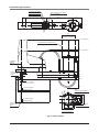
1
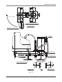
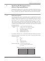
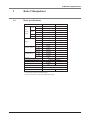
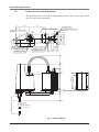
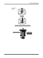
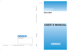
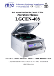
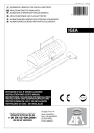
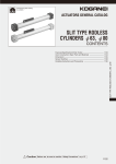
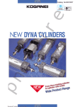
Cat. No. I142E-EN-01
Cat. No. I142E-EN-01
SCARA Robots
XS
Series
ZX-T
Series
R6Y - XS series
SCARA Robots, R6Y - XS series
USER´S MANUAL
USER´S MANUAL
Authorized Distributor:
Cat. No. I142E-EN-01
Note: Specifications subject to change without notice.
Printed in Europe
Copyright
The following shall be described in the Copyright section and the description
shall not be changed without permission.
OMRON, 2010
All rights reserved. No part of this publication may be reproduced, stored in
a retrieval system, or transmitted, in any form, or by any means, mechanical,
electronic, photocopying, recording, or otherwise, without the prior written permission of OMRON.
No patent liability is assumed with respect to the use of the information contained herein. Moreover, because OMRON is constantly striving to improve
its high-quality products, the information contained in this manual is subject
to change without notice. Every precaution has been taken in the preparation
of this manual. Nevertheless, OMRON assumes no responsibility for errors or
omissions. Neither is any liability assumed for damages resulting from the use
of the information contained in this publication.
Introduction
This user’s manual was prepared for XS series ceiling-hanging/inverse type
models (R6YXSH300 to R6YXS1000) of the OMRON industrial robots.
This user’s manual describes the safety measures, handling, adjustment and
maintenance of XS series robots for correct, safe and effective use. Be sure to
read this manual carefully before installing the robot. Even after you have read
this manual, keep it in a safe and convenient place for future reference.
This user’s manual should be used with the robot and considered an integral
part of it. When the robot is moved, transferred or sold, send this manual to the
new user along with the robot. Be sure to explain to the new user the need to
read through this manual.
For the operating or maintenance procedures not described in this manual,
please refer to the separate “X Series User’s Manual”. Also refer to the “X Series User’s Manual” for precautions and warranty. If there are any
obscure points in handling the robot, be sure to contact OMRON sales office or
dealer.
For details on specific operation and programming of the robot, refer to the
separate “OMRON Robot Controller User’s Manual”.
Disclaimers
CHANGE IN SPECIFICATIONS
Product specifications and accessories may be changed at any time based on improvements
and other reasons. It is our practice to change model numbers when published ratings or
features are changed, or when significant construction changes are made. However, some
specifications of the products may be changed without any notice. When in doubt, special
model numbers may be assigned to fix or establish key specifications for your application on
your request. Please consult with your OMRON representative at any time to confirm actual
specifications of purchased products.
DIMENSIONS AND WEIGHTS
Dimensions and weights are nominal and are not to be used for manufacturing purposes, even
when tolerances are shown.
PERFORMANCE DATA
Performance data given in this manual is provided as a guide for the user in determining
suitability and does not constitute a warranty. It may represent the result of OMRON’s
test conditions, and the users must correlate it to actual application requirements. Actual
performance is subject to the OMRON Warranty and Limitations of Liability.
ERRORS AND OMISSIONS
The information in this manual has been carefully checked and is believed to be accurate;
however, no responsibility is assumed for clerical, typographical, or proofreading errors, or
omissions.
CONTENTS
CHAPTER 1 Functions
1 Robot Manipulator...............................................................1-1
2 Robot Parameters.................................................................1-4
CHAPTER 2 Installation
1 Installation Base...................................................................2-1
2 Installation............................................................................2-2
2-1 Unpacking.......................................................................................................... 2-2
2-2 Checking the product.......................................................................................... 2-3
2-3 Moving the robot................................................................................................ 2-4
2-3-1 Moving the R6YXSH300, R6YXSH400............................................................. 2-4
2-3-2 Moving the R6YXS500, R6YXS600, R6YXS700, R6YXS800, R6YXS1000.. 2-5
2-3-2-1
Moving the ceiling-hanging robot...................................................... 2-5
2-3-2-2
Moving the inverse type robot......................................................... 2-10
CHAPTER 3 Periodic Inspection
1 Replacing the Harmonic Grease
(Inverted ceiling-hanging/inverse type model R-axis).........3-1
1-1 Replacement period............................................................................................ 3-1
CHAPTER 4 Specifications
1 Robot Manipulator...............................................................4-1
1-1 Basic specifications............................................................................................ 4-1
1-2 External view and dimensions............................................................................ 4-4
CHAPTER 1
Functions
1 Robot Manipulator............................................................................. 1-1
2 Robot Parameters............................................................................... 1-4
CHAPTER 1 Functions
1
Robot Manipulator
XS series robots are grouped into the ceiling-hanging models of Fig. 1-1 and
the inverse type models of Fig. 1-2. Jog key movement is in the directions
shown in Figs. 1-1 and 1-2.
Robot part names and functions are shown in Fig. 1-3 and Fig. 1-4.
Fig. 1-1 Ceiling-hanging models
Fig. 1-2 Inverse type models
1-1
CHAPTER 1 Functions
User tubing 1 (φ4 black)
User tubing 2 (φ4 red)
User tubing 3 (φ4 blue)
M4 ground terminal
Serial label
D-sub connector for user wiring (No.1 to 10)
D-sub connector for user wiring
(No.1 to 10)
Machine harness
User tubing 1 (φ4 black)
User tubing 2 (φ4 red)
User tubing 3 (φ4 blue)
Ball screw
Robot cable
Warning label 1
Warning label 3
Warning label 2
R-axis motor
X-axis motor
Z-axis motor
Y-axis motor
X-axis speed
reduction gear
Y-axis arm
R-axis speed
reduction gear
Z-axis spline
End effector attachment
Y-axis speed
reduction gear
Y-axis mechanical stopper
X-axis mechanical stopper
X-axis arm
Z-axis,R-axis pulley, belt
Fig. 1-3 R6YXSH300, R6YXSH400 ceiling-hanging/inverse type robots
In the case of the ceiling-hanging/inverse type models, the robot base up/down
installation directions in the figure are reversed.
1-2
CHAPTER 1 Functions
Y-axis mechanical stopper
User tubing 2 (φ6 red)
User tubing 3 (φ6 blue)
D-sub connector for user wiring (No.1 to 20)
User tubing 1 (φ6 black)
Robot cable
Warning label 2 (Same on opposite side)
Warning label 1 (Same on opposite side)
Ball screw
User tubing 3 (φ6 blue)
User tubing 2 (φ6 red)
User tubing 1 (φ6 black)
D-sub connector for user wiring
(No.1 to 20)
M4 ground terminal
Machine harness
Serial label
R-axis motor
Z-axis motor
Y-axis motor
Warning label 3
X-axis motor
Y-axis speed
reduction gear
R-axis speed reduction gear
Z-axis spline
X-axis speed
reduction gear
Y-axis arm
Z-axis,R-axis pulley, belt
End effector attachment
X-axis arm
Carrying jig installation position
Machine harness
X-axis movable mechanical stopper
Fig. 1-4 R6YXS500 to R6YXS1000 ceiling-hanging/inverse type robots
In the case of the ceiling-hanging/inverse type models, the robot base up/down
installation directions in the figure are reversed.
1-3
CHAPTER 1 Functions
2
Robot Parameters
A portion of the robot parameters for ceiling-hanging/inverse type models are
changed from the standard specifications when shipped.
The following is a description of these changed parameters and precautions you
should take when using these robots.
To purchasers of this robot
At this time our sincere thanks for your purchase of this robot.
This robot is made to custom specifications so some parameters are different
from standard robots. Please be aware of the following points before attempting
to use the robot.
Cautions regarding use
Always make a backup of parameters.
Initializing the parameters voids all parameters that were entered. When
initialized, load the backup parameters.
Parameter changes
A description of parameter changes is given below. Boxes left blank indicate
standard specifications.
(1) Ceiling-hanging model
Axis settings
Parameter
Axis parameters
16. Motor direction
Changes
Y-axis Z-axis
R-axis
X-axis
Changes
Y-axis Z-axis
+++
R-axis
---
Axis settings (R6YXSH300, R6YXSH400)
Parameter
X-axis
Axis parameters
37. Max. motor rotation
Changes
Y-axis Z-axis
X-axis
+++
(2) Inverse type models
Axis settings
Parameter
Axis parameters
16. Motor direction
Axis settings (R6YXS500, R6YXS600, R6YXS700, R6YXS800, R6YXS1000)
Parameter
Changes
X-axis Y-axis Z-axis
Axis parameters
37. Max. motor rotation
1-4
R-axis
6000
R-axis
4000
CHAPTER 1 Functions
(3) R6YXSH300
Axis settings
Parameter
Axis parameters
11. Arm length [mm]
X-axis
175.00
Changes
Y-axis Z-axis
125.00
Robot numbers used to initialize the parameters are as follows
Robot numbers
2101
2102
2103
2104
2105
2106
2107
2110
2111
2112
2113
2114
Robot model
R6YXSH300
R6YXSH400
R6YXS500
Z200
R6YXS600
Z200
R6YXS700
Z200
R6YXS800
Z200
R6YXS1000
Z200
R6YXS500
Z300
R6YXS600
Z300
R6YXS700
Z400
R6YXS800
Z400
R6YXS1000
Z400
Manufacturer serial No.
Controller serial No.
1-5
R-axis
CHAPTER 2
Installation
1 Installation Base................................................................................. 2-1
2 Installation.......................................................................................... 2-2
2-1
2-2
2-3
Unpacking................................................................................................................. 2-2
Checking the product................................................................................................ 2-3
Moving the robot....................................................................................................... 2-4
2-3-1
Moving the R6YXSH300, R6YXSH400.................................................................. 2-4
2-3-2
Moving the R6YXS500, R6YXS600, R6YXS700, R6YXS800, R6YXS1000........ 2-5
2-3-2-1 Moving the ceiling-hanging robot............................................................. 2-5
2-3-2-2 Moving the inverse type robot................................................................. 2-10
CHAPTER 2 Installation
1
Installation Base
1) Please read the description of standard robot models for the installation
base and comply with the caution items provided.
WARNING
THE CEILING-HANGING/INVERSE TYPE ROBOT MODELS ARE HUNG
FROM THE CEILING SO A DANGEROUS SITUATION CAN OCCUR IF THE
ROBOT SUPPORT SECTION BREAKS AND THE ROBOT FALLS. MAKE
SURE THE ROBOT SUPPORT SECTION HAS SUFFICIENT STRENGTH,
RIGIDITY AND SAFETY.
CAUTION
•WHEN USING THE R6YXSH300 AND R6YXSH400, MAKE SURE THAT THE ARM DOES NOT INTERFERE WITH THE BASE INSTALLATION SECTION.
•WHEN USING THE R6YXS500 TO R6YXS1000, MAKE SURE THAT THE MACHINE HARNESS AND Y-AXIS ARM UPPER COVER DO NOT INTERFERE WITH THE BASE INSTALLATION SECTION.
SEE “1-2 EXTERNAL VIEW AND DIMENSIONS” IN CHAPTER 4.
2) Tap the required holes into the surface of the installation base. See “1-2 External view and dimensions” in Chapter 4 for how to tap the holes.
2-1
CHAPTER 2 Installation
2
Installation
2-1
Unpacking
WARNING
THE ROBOT AND CONTROLLER ARE HEAVY. TAKE SUFFICIENT CARE
NOT TO DROP THEM DURING MOVING OR UNPACKING AS THIS MAY
DAMAGE THE EQUIPMENT OR CAUSE BODILY INJURY.
CAUTION
WHEN MOVING THE ROBOT OR CONTROLLER BY EQUIPMENT SUCH
AS A FOLK-LIFT THAT REQUIRES A LICENSE, ONLY PROPERLY
QUALIFIED PERSONNEL MAY OPERATE IT. THE EQUIPMENT AND
TOOLS USED FOR MOVING THE ROBOT SHOULD BE SERVICED DAILY.
The XS series robot comes packed with a robot controller and accessories,
according to the order specifications. Using a carrying cart (dolly) or forklift,
move the package to near the installation base. Take sufficient care not to apply
shocks to the equipment when unpacking it.
Robot manipulator
R6YXS500, R6YXS600, R6YXS700,
R6YXS800, R6YXS1000 Ceiling-hanging models
Case
Robot manipulator
R6YXSH300,
R6YXSH400
Arm clamping stay
(Remove after installation.)
Robot carrying jig
Arm clamping stay
(Remove after installation.)
Robot controller
and accessories
Robot manipulator
R6YXS500, R6YXS600, R6YXS700,
R6YXS800,R6YXS1000
Inverse type models
Fig. 2-1 Packed state
2-2
CHAPTER 2 Installation
2-2
Checking the product
After unpacking, check the product configuration and conditions.
The illustration below shows typical configurations for R6YXS500 to
R6YXS1000 ceiling-hanging/inverse type models, which are different from
standard models.
CAUTION
IF THERE IS ANY DAMAGE DUE TO TRANSPORTATION OR
INSUFFICIENT PARTS, PLEASE NOTIFY YOUR OMRON SALES OFFICE
OR DEALER IMMEDIATELY.
Controller : YRC v.1
Robot
: R6YXS500, R6YXS600, R6YXS700, R6YXS800, R6YXS1000
STD. DIO
connector (x1)
PB
terminator (x1)
CD-ROM User’s Manual
or
User’s Manual
Warning label (x1)
Robot manipulator
XS series
OP.1
MO
TOR
OP.3
D-sub connector/hood (x2)
YRC
PB
PWR
SRV
ERR
XM
ROB
I/O
XY
SE L
YM
T
B AT
XY
COM
ROB
I/O
OP.2
.DIO
STD
B AT
ZR
OP.4
A
X
Z
P
N
ZR
ZM
T
ACIN
L
B
Y
R
Origin position stickers (x2)
(R6YXS500,R6YXS600 x3)
N
Y
E T
SAF
L1
N1
RM
Covers (x2)
TOP 14
EX T.E-S 13−
PIN
YRC robot controller
Screws (x4)
Fig. 2-2 Product configurations
2-3
CHAPTER 2 Installation
2-3
Moving the robot
WARNING
SERIOUS INJURY MAY OCCUR IF THE ROBOT FALLS AND PINS
SOMEONE UNDER IT.
•DO NOT ALLOW ANY PART OF YOUR BODY TO ENTER THE AREA BENEATH THE ROBOT DURING WORK.
•ALWAYS WEAR A HELMET, SAFETY SHOES AND GLOVES DURING WORK.
To check the mass of each robot, refer to “1-1 Basic specifications” in Chapter 4.
2-3-1
Moving the R6YXSH300, R6YXSH400
1) Fold the X and Y axis arms as shown in Fig. 2-3, and wind the robot cable
around the machine harness, then fasten the robot cable with adhesive tape
so as not to cover the bolt installation holes.
When moving an inverted ceiling-hanging robot, wind the robot cable
around the spline shaft as shown and fasten the cable with adhesive tape.
2) Holding the support parts as shown in the figure with both hands, place the
robot on the installation base and secure it temporarily by tightening the
bolts.
(For tightening torque to secure the robot firmly, see “2-4 Installing the robot” in the X standard model user’s manual.)
Robot cable
Robot cable
Bolt installation hole
Support part
Support part
Support part
Bolt installation hole
Support part
Fig. 2-3
2-4
CHAPTER 2 Installation
2-3-2
Moving the R6YXS500, R6YXS600, R6YXS700, R6YXS800,
R6YXS1000
WARNING
SERIOUS INJURY MAY OCCUR IF THE ROBOT FALLS AND PINS
SOMEONE UNDER IT.
•CHECK THAT THERE ARE NO CRACKS AND CORROSION ON THE EYEBOLT INSTALLATION. IF FOUND, DO NOT USE EYEBOLTS TO MOVE THE ROBOT.
•INSERT THE EYEBOLTS INTO THE HOLES OF THE CARRYING JIG SO THAT THEIR BEARING SURFACES MAKE TIGHT CONTACT WITH EACH
OTHER, AND SECURELY FASTEN THE EYEBOLTS WITH THE NUTS. •USE A HOIST AND ROPE WITH CARRYING CAPACITY STRONG
ENOUGH TO SUPPORT THE ROBOT WEIGHT.
•MAKE SURE THE ROPE STAYS SECURELY ON THE HOIST HOOK. •REMOVE ALL LOADS ATTACHED TO THE ROBOT MANIPULATOR
END. IF ANY LOAD IS STILL ATTACHED, THE ROBOT MAY LOSE
BALANCE WHILE BEING CARRIED, AND TOPPLE OVER CAUSING
ACCIDENTS.
CAUTION
•WHEN MOVING THE ROBOT BY EQUIPMENT SUCH AS CRANES THAT
REQUIRE A LICENSE, ONLY PROPERLY QUALIFIED PERSONNEL MAY
OPERATE IT. •THE EQUIPMENT AND TOOLS USED FOR MOVING THE ROBOT
SHOULD BE SERVICED DAILY.
To move a robot (for example, the R6YXS500) correctly and safely, follow the
procedure below. Use the same procedure to move other robots.
2-3-2-1
Moving the ceiling-hanging robot
(1) When using eyebolts (See Fig. 2-4.)
1) Remove the X-axis and Y-axis under covers and attach the carrying jigs
as shown in Fig. 2-4. Remove all loads if attached to the Z-axis to set the
servo free and release the brake. Then fold the Z-axis to a position where it
can be fastened to the arm clamping stay.
2) Insert the eyebolts into the holes on the carrying jig and securely fasten the
eyebolts with the nuts. Then attach the arm clamping stay to the carrying
jig.
2-5
CHAPTER 2 Installation
3) Clamp the Y-axis arm by using the stay and bolts that come with the robot.
If the arms cannot be folded in the carrying position (see Fig. 2-4) due to
the X-axis mechanical stoppers, then remove them. (When the robot is
shipped, the mechanical stoppers are installed to provide the maximum
movement range.)
4) Wind the robot cable around the robot base while keeping the cable from
hanging up on the base mount, then fasten the cable end with adhesive
tape.
5) Prepare 4 looped ropes with the same length to allow a good lifting
balance, then pass each rope through each eyebolt and catch it on the hoist
hook.
6) Slightly lift the hoist so that each rope has light tension to hold the robot. In
this state, remove the bolts securing the robot base to the pallet supplied or
installation base (if robot is to be moved to another installation base).
7) Using caution to keep the balance of the robot and avoid subjecting it to
any strong vibrations and shocks, operate the hoist carefully to move to the
installation base. The angle between each rope and the arm surface should
be kept at 45 degrees or more.
8) Temporarily secure the robot to the installation base by tightening the bolts.
(Use the same tightening torque as specified to secure the standard model
robots.)
9) Remove the ropes and carrying jigs, then reattach the X-axis and Y-axis
under covers. Be sure to keep the carrying jigs, eyebolts, arm clamping
stay, bolts and pallet for future use in case the robot needs to be moved or
transported.
2-6
CHAPTER 2 Installation
Arm clamping stay
(supplied with robot)
Eyebolts (4 pieces supplied with the robot)
Arm clamped position
Bolts (M12x20) supplied with robot
Tightening torque 71N•m (720kgf•cm)
Hoist hook
Rope
Robot cable
Use bolts and nuts or screws
(4 pcs) supplied with robot
4 bolts (supplied with robot)
Tightening torque
71N•m (720kgf•cm)
Robot carrying jig
Pallet (supplied with the robot)
Bolts (2 pcs) supplied with robot
Tightening torque 4.5N•m (46kgf•cm)
Y-axis under cover
Fig. 2-4
2-7
Screw
X-axis under cover
CHAPTER 2 Installation
(2) When using the hand forklift (See Fig. 2-5)
1) Remove the X- and Y-axis under covers and install the robot carrying jigs.
2) Set the X- and Y-axis arms straight (See Fig. 2-5). If the robot is in the
shipped state, remove the spline from the arm clamping stay, and set the
X- and Y-axis arms straight. If the arms cannot be folded in the carrying
position (see Fig. 2-5) due to the X-axis mechanical stoppers, then remove
them.
3) Wind the robot cable around the robot base while keeping the cable from
hanging up on the base mount, then fasten the cable end with adhesive
tape.
4) Insert the prongs of the hand forklift into the robot carrying jigs and raise
the hand forklift supporting the robot. Remove the bolts securing the
pallet supplied or installation base (if moving the robot to another installation base).
5) Using caution to keep the balance of the robot and avoid subjecting it to
vibrations and shocks, slowly move to the installation base.
6) Temporarily secure the robot to the installation base by tightening the bolts.
(Bolt tightening torque is the same as the standard model robots.)
7) Remove the carrying jigs, and reattach the X- and Y-axis under covers. Be
sure to keep the carrying jigs, bolts, arm clamping stay and pallet for future
use in case the robot needs to be moved or transported.
2-8
CHAPTER 2 Installation
Set the arms out straight.
Arm clamping stay (supplied with robot)
Arm clamped position
Bolts (M12x20) supplied with robot
Robot cable
4 bolts (supplied with robot)
Tightening torque
71N•m (720Kgf•cm)
Use bolts and nuts or screws
(4 pcs) supplied with robot
Robot carrying jig
Insert the prongs of
the hand forklift there.
Pallet (supplied with the robot)
Bolts (2 pcs) supplied with robot
Y-axis under cover
Fig. 2-5
2-9
Screw
X-axis under cover
CHAPTER 2 Installation
2-3-2-2
Moving the inverse type robot
(1) When using eyebolts (See Fig. 2-6.)
1) Remove the X-axis and Y-axis upper covers and attach the robot carrying
jigs. Remove all loads if attached to the Z-axis to set the servo free and
release the brake. Then fold the Z-axis to a position where it can be fastened to the arm clamping stay
2) Insert the eyebolts into the holes on the carrying jigs and securely fasten the eyebolts with the nuts. Then attach the arm clamping stay to the
carrying jigs.
3) Clamp the Y-axis arm by using the stay and bolts that come with the robot.
If the arms cannot be folded in the carrying position (see Fig. 2-4) due to
the X-axis mechanical stoppers, then remove them. (When the robot is
shipped, the mechanical stoppers are installed to provide the maximum
movement range.)
4) Wind the robot cable around the robot base while keeping the cable from
hanging up on the base mount, then fasten the cable end with adhesive
tape.
5) Prepare 4 looped ropes with the same length to allow a good lifting
balance, then pass each rope through each eyebolt and catch it on the hoist
hook.
6) Slightly lift the hoist so that each rope has light tension to hold the robot. In
this state, remove the bolts securing the robot base to the pallet supplied or
installation base (if moving the robot to another installation base).
7) Using caution to keep the balance of the robot and avoid subjecting it to
any strong vibrations and shocks, operate the hoist carefully to move to the
installation base. The angle between each rope and the arm surface should
be kept at 45 degrees or more.
8) Temporarily secure the robot to the installation base by tightening the bolts.
(Bolt tightening torque is the same as the standard model robots.)
9) Remove the ropes and carrying jigs, then reattach the X-axis and Y-axis
upper covers. Be sure to keep the carrying jigs, eyebolts, arm clamping
stay, bolts and pallet for future use in case the robot needs to be moved or
transported.
2-10
CHAPTER 2 Installation
Hoist hook
X-axis upper cover
Y-axis upper cover
Rope
Screw
Eyebolts (4 pieces supplied with the robot)
2 bolts (supplied with robot)
Tightening torque
4.5N•m (46kgf•cm)
Robot carrying jig
4 bolts (supplied with robot)
Tightening torque
71N•m (720kgf•cm)
Robot cable
Use bolts and nuts or screws
supplied with robot
Pallet (supplied with the robot)
Bolts (M12×20) supplied with robot
Tightening torque 71N•m (720kgf•cm)
Arm clamping stay (supplied with robot)
Arm clamped position
Fig. 2-6
2-11
CHAPTER 2 Installation
(2) When using the hand forklift (See Fig. 2-7)
1) Remove the X- and Y-axis upper covers and install the robot carrying jigs.
2) Set the X- and Y-axis arms straight (See Fig. 2-5). If the robot is in the
shipped state, remove the spline from the arm clamping stay, and set the
X- and Y-axis arms straight. If the arms cannot be folded in the carrying
position (see Fig. 2-5) due to the X-axis mechanical stoppers, then remove
them. (When the robot is shipped, the mechanical stoppers are installed to
provide the maximum movement range.)
3) Wind the robot cable around the robot base while keeping the cable from
hanging up on the base mount, then fasten the cable end with adhesive
tape.
4) Insert the prongs of the hand forklift into the robot carrying jigs and raise
the hand forklift supporting the robot. Remove the bolts securing the
pallet supplied or installation base (if moving the robot to another installation base).
5) Using caution to keep the balance of the robot and avoid subjecting it to
vibrations and shocks, slowly move to the installation base.
6) Temporarily secure the robot to the installation base by tightening the bolts.
(Bolt tightening torque is the same as the standard model robots.)
7) Remove the carrying jigs, and reattach the X- and Y-axis upper covers. Be
sure to keep the carrying jigs, bolts, arm clamping stay and pallet for future
use in case the robot needs to be moved or transported.
2-12
CHAPTER 2 Installation
X-axis upper cover
Y-axis upper cover
Screw
Eyebolts (4 pieces supplied with the robot)
2 bolts (supplied with robot)
Insert the prongs of the hand forklift there.
Insert the prongs of the hand forklift there.
Robot carrying jig
4 bolts (supplied with robot)
Tightening torque
71N•m (720kgf•cm)
Robot cable
Use bolts and nuts or
screws supplied with robot
Pallet (supplied with the robot)
Bolts (M12×20) supplied with robot
Arm clamping stay (supplied with robot)
Set the arms out straight.
Arm clamped position
Fig. 2-7
2-13
CHAPTER 3
Periodic Inspection
1 Replacing the Harmonic Grease (Inverse type model R-axis)........... 3-1
1-1
Replacement period................................................................................................... 3-1
CHAPTER 3 Periodic Inspection
1
Replacing the Harmonic Grease
(Inverse type model R-axis)
Only the R-axis harmonic drive of the inverse type model uses harmonic grease
HC-1A. This grease must be replaced periodically. Use the guideline explained
below to determine the appropriate replacement period and replace the grease.
1-1
Replacement period
The harmonic drive grease replacement period is determined by the total
number of turns of the wave generator used in the harmonic drive. It is recommended to replace the harmonic drive grease when the total number of turns
has reached 1.5×10⁸ (at ambient operating temperatures of 0°C to +40°C).
This means that the replacement period will differ depending on the following operating conditions. If the robot operation duty ratio is high or the robot
is operated in environments at higher temperatures, the harmonic drive should
be replaced earlier.
Replacement period= 1.5×10⁸/(n×60×h×D×N×θ) years
where
n : Number of axis movements per minute
θ
: Average turn per axis movement
N : Speed reduction ratio
h : Operation time per day
D : Operation days per year
For example, when the robot is used under the following conditions, the replacement period for the R-axis harmonic drive grease of the R6YXS500 can be
calculated as follows.
n
: 10
θ
: 0.25
N : 80
h
: 24 hours per day
D : 240 days per year
Replacement period= 1.5×10⁸/(n×60×h×D×N×θ)
= 1.5×10⁸/(10×60×24×240×80×0.25)
= 2.17 years
Table 3-1 Harmonic drive speed reduction ratio
Robot model
R6YXSH300, R6YXSH400
R-axis
50
R6YXS500, R6YXS600
50
R6YXS700, R6YXS800
50
R6YXS1000
50
3-1
CHAPTER 4
Specifications
1 Robot Manipulator............................................................................. 4-1
1-1
1-2
Basic specifications................................................................................................... 4-1
External view and dimensions.................................................................................. 4-4
CHAPTER 4 Specifications
1
Robot Manipulator
1-1
Basic specifications
Robot model
R6YXSH300
R6YXSH400
Arm length
175mm
225mm
Rotation angle
±115°
±115°
Arm length
125mm
175mm
Rotation angle
±140°
±140°
Z-axis
Stroke
150mm
150mm
R-axis
Rotation angle
±180°
±180°
X-axis
200W
200W
Y-axis
100W
100W
Z-axis
100W
100W
R-axis
100W
100W
XY resultant
4.4m/s
6.0m/s
Z-axis
1.0m/s
1.0m/s
R-axis
1020°/s
1020°/s
XY-axes
±0.01mm
±0.01mm
Z-axis
±0.01mm
±0.01mm
R-axis
±0.005°
±0.005°
3kg
3kg
X-axis
Axis
Y-axis
specifications
Motor
Maximum speed
Repeatability *1
Payload
R-axis tolerable moment of inertia *2
User wiring
0.05kgm2 (0.5kgfcms2)
10 cables
10 cables
4x3
4x3
User tubing (Outer diameter)
Travel limit
1.Soft limit 2.Mechanical limit (XYZ-axes)
Robot cable
3.5m (option: 5m, 10m)
Weight
15kg
*1 At constant ambient temperature (XY)
*2 There are limits to acceleration coefficient settings.
4-1
15kg
CHAPTER 4 Specifications
Robot model
R6YXS500
R6YXS600
Arm length
250mm
350mm
Rotation angle
±120°
±120°
Arm length
250mm
250mm
Rotation angle
±135°
±145°
Z-axis
Stroke
200,300mm
200,300mm
R-axis
Rotation angle
±180°
±180°
X-axis
400W
400W
Y-axis
200W
200W
Z-axis
200W
200W
R-axis
100W
100W
XY resultant
4.9m/s
5.6m/s
Z-axis
1.7m/s
1.7m/s
X-axis
Axis
specifi-
Y-axis
cations
Motor
Maximum speed
Repeatability *1
R-axis
876°/s
876°/s
XY-axes
±0.02mm
±0.02mm
Z-axis
±0.01mm
±0.01mm
R-axis
±0.005°
±0.005°
10kg
10kg
Payload
R-axis tolerable moment of inertia *2
User wiring
0.12kgm2 (1.2kgfcms2)
20 cables
20 cables
6x3
6x3
User tubing (Outer diameter)
Travel limit
1.Soft limit 2.Mechanical limit (XYZ-axes)
Robot cable
3.5m (option: 5m, 10m)
Weight
30kg
*1 At constant ambient temperature (XY)
*2 There are limits to acceleration coefficient settings.
4-2
32kg
CHAPTER 4 Specifications
Robot Model
X-axis
Axis
specifications
Y-axis
Z-axis
Arm length
R6YXS800
R6YXS1000
350mm
450mm
550mm
Rotation angle
±120°
±120°
±120°
Arm length
350mm
350mm
450mm
Rotation angle
±145°
±145°
±145°
Stroke
200,400mm
200,400mm
200,400mm
±180°
±180°
±180°
X-axis
800W
800W
800W
Y-axis
400W
400W
400W
R-axis Rotation angle
Motor
R6YXS700
Z-axis
400W
400W
400W
R-axis
200W
200W
200W
XY resultant
6.7m/s
7.3m/s
8.0m/s
Maximum speed
Z-axis
1.7m/s
1.7m/s
1.7m/s
R-axis
600°/s
600°/s
600°/s
Repeatability *1
X,Y-axes
±0.02mm
±0.02mm
±0.02mm
Z-axis
±0.01mm
±0.01mm
±0.01mm
R-axis
±0.005°
±0.005°
±0.005°
20kg
20kg
Payload
R-axis tolerable moment of inertia *2
User wiring
User tubing (Outer diameter)
20kg
0.32kgm (3.2kgfcms )
2
2
20 cables
20 cables
20 cables
6x3
6x3
6x3
Travel limit
1.Soft limit 2.Mechanical limit (XYZ-axes)
Robot cable
3.5m,option:5m,10m
Weight
56kg
57kg
At constant ambient temperature (XY)
*12 There
are limits to acceleration coefficient settings.
*
4-3
58kg
CHAPTER 4 Specifications
1-2
External view and dimensions
The drawing below is for the ceiling-hanging robots. The inverse type robots
also have the same dimensions.
37
112.2
175
42
D-sub connector for user wiring
(No.1 to 10)
0
38
R5
D-sub connector for user wiring
(No.1 to 10)
M4 ground terminal
131
140
65
74
55
13
100
125
12
5
9. User tubing 1 (φ4 black)
R3
User tubing 2 (φ4 red)
User tubing 3 (φ4 blue)
User tubing 1 (φ4 black)
40
User tubing 2 (φ4 red)
72
User tubing 3 (φ4 blue)
103
381
290
230
187
0
15
36
φ54
4-φ9
Use M8 bolt for installation
62
52
φ31
142±2
150 Z-axis stroke
0
φ16h7 -0.018
M8×1.25 Depth 15
Fig. 4-1 R6YXSH300
4-4
135
25
185.5
168
120
CHAPTER 4 Specifications
(Use this when tightening M8
φ3 +0.2
0
screw at lower part.)
Z-axis mechanical stopper
41
36(φ16 Range)
Circlip for user tool positioning
Spline shaft (hollow) Hollow diameter φ7
0
φ16h7 -0.018
M8×1.25 Depth15
Z-axis tip shape
°
140
5°
11
5°
°
11
140
R3
13
00
R1
R1
25
86°
86°
226
Base interference range
Working envelope
Use caution to prevent interference with installation wall
Inverse type is installed upside down.
4-5
CHAPTER 4 Specifications
37
166.1
225
42
D-sub connector for user wiring
(No.1 to 10)
M4 ground terminal
131
D-sub connector for user wiring
(No.1 to 10)
140
74
55
13
65
175
100
R5
0
38
12
User tubing 1 (φ4 black)
R3
9.
5
User tubing 1 (φ4 black)
User tubing 2 (φ4 red)
User tubing 2 (φ4 red)
User tubing 3 (φ4 blue)
User tubing 3 (φ4 blue)
40
72
103
381
290
230
187
φ54
0
15
4-φ9
36
Use M8 bolt
for installation
62
52
φ31
1150 Z-axis stroke
142±2
φ16h7
0
-0.018
M8×1.25 Depth 15
Fig. 4-2 R6YXSH400
4-6
135
25
185.5
168
120
CHAPTER 4 Specifications
(Use this when tightening M8
φ3 +0.2
0
screw at lower part.)
Z-axis mechanical stopper
41
36(φ16 Range)
Circlip for user tool positioning
Spline shaft (hollow) Hollow diameter φ7
0
φ16h7 -0.018
M8×1.25 Depth15
Z-axis tip shape
5°
45
00
R1
5°
11
11
0°
14
0°
14
R4
96°
226
96°
Base interference range
Working envelope
Use caution to prevent interference with installation wall
Inverse type is installed upside down.
4-7
CHAPTER 4 Specifications
47
250
120
250
90
94
User tubing 3 (ø6 blue)
R55
User tubing 2 (ø6 red)
D-sub connector for user wiring (No.1 to 20)
User tubing 1 (ø6 black)
ø205
(Installation base of larger than
ø205mm may interfere with harness.)
228 Z300mm stroke
Recommended user
installation base
93 Z200mm stroke
60
8
0
15
91
36
2X2-M4X0.7
Depth10
(Same on opposite side)
284
Z-axis upper end
mechanical stopper position
54
20
319
ø7
8
411±2
0
ø18 -0.018
A
200
M12x1.75 Depth 20
86
Z-axis300mm stroke
Working envelope
Center of recommended
user installation base
110
R200
65
70
12
12
R2
0
R80
Z-axis200mm stroke
Working envelope
Z-axis lower end
mechanical
stopper position
65
300
517
160
41
48
364
8
57
73
166 (Base size)
View from direction A
Fig. 4-3 R6YXS500
4-8
4-ø11
Use M10 bolt for installation
CHAPTER 4 Specifications
0˚
12
R1
91
0˚
Interference position
(a) Base flange
(b) Base rear side
(c) Base
0
R50
12
)
R93(a
R111(c)
0
R25
(b)
R67
135˚
135˚
3(c)
R18
3
R10
)
5(a
R8
˚
122
0
R50
122
˚
Working envelope
R250
R59(b)
137˚
137˚
X and Y-axis mechanical stopper positions (maximum working envelope)
2
0
0
35
55
73
53
User tubing 3(ø6 blue)
D-sub connector for user wiring
(No.1 to 20)
User tubing 2(ø6 red)
User tubing 1(ø6 black)
M4 ground terminal
4-9
CHAPTER 4 Specifications
User tubing 2 (ø6 red)
120
94
User tubing 3 (ø6 blue)
350
90
250
R55
47
D-sub connector for user wiring
(No. 1 to 20 usable)
User tubing 1 (ø6 black)
ø205
(Installation base of larger than
ø205mm may interfere with harness.)
228 Z-axis 300mm stroke
Recommended user
installation base
Z-axis 200mm stroke
93
60
8
0
15
91
36
2X2-M4X0.7
Depth10
(Same on
opposite side)
Z-axis upper end
mechanical stopper position
54
ø7
20
319
48
41
364
8
411±2
0
ø18 -0.018
A
527
Z-axis stroke 300mm
Working envelope
86
Center of recommended
user installation base
65
70
12
R200
160
12
0
0
R2
R8
Z-axis stroke 200mm
Working envelope
110
65
300
200
M12X1.75 Depth20
Z-axis lower end
mechanical stopper position
8
57
73
166(Base size)
View from direction A
Fig. 4-4 R6YXS600
4-10
4-ø11
Use M10 bolt for installation
R106(a)
0°
R6
00
R12
4(c
)
12
Interference position
(a) Base flange
(b) Base rear side
(c) Base
12
0°
CHAPTER 4 Specifications
04
R2
50
R2
(b)
R80
°
145
145°
°
122
96
R1
°
R6
0
R116 0
(c)
122
R116(a)
Working envelope
50
R2
)
2(b
R7
147°
147°
X and Y-axis mechanical stopper positions (maximum working envelope)
2
0
0
35
55
73
53
User tubing 3 (ø6 blue)
D-sub connector for user wiring
(No. 1 to 20 usable, pin contact)
User tubing 2 (ø6 red)
User tubing 1 (ø6 black)
M4 ground terminal
4-11
CHAPTER 4 Specifications
User tubing 1 (ø6 black)
User tubing 2 (ø6 red)
D-sub connector for user wiring(No. 1 to 20 usable)
User tubing 3 (ø6 blue)
350
350
147
R76
106
126
58
ø232
(Installation base of larger than
ø232mm may interfere with harness.)
301 Z-axis 400mm stroke
Recommended user
installation base
120
101 Z-axis 200mm stroke
5
0
20
2X2-M4X0.7
Depth10
(Same on opposite side)
41
97
279
54
ø8
20
328
45
375
419±2
8
0
ø22 -0.021
M12X1.75 Depth20
562
Z-axis stroke 200mm
Working envelope
12
0
5
4-ø14
Use M12 bolt for installation
6
R10
R2
R150
75
12
70
112
Z-axis stroke 400mm
Working envelope
75
400
200
A
180
50.5
Z-axis upper end
mechanical stopper position
Z-axis lower end
mechanical stopper position
70
106
80
93
View from direction A
Fig. 4-5 R6YXS700
4-12
Center of recommended
user installation base
CHAPTER 4 Specifications
4(c
)
00
R7
10
R10
0˚
12
R2
)
5(a
R9
50
12
0˚
Interference position
(a) Base flange
(b) Base rear side
(c) Base
R3
R60(b)
145˚
145˚
Working envelope
00
(a)
R83
R3
50
R7
(c)
˚
123
˚
123
99
R1
R93
)
8(b
R4
147˚
147˚
X and Y-axis mechanical stopper positions (maximum working envelope)
4
0
0
41
61
79
59
D-sub connector for user wiring
(No. 1 to 20 usable, pin contact)
User tubing 3 (ø6 blue)
User tubing 2 (ø6 red)
User tubing 1 (ø6 black)
4-13
CHAPTER 4 Specifications
User tubing 1 (ø6 black)
User tubing 2 (ø6 red)
User tubing 3 (ø6 blue)
D-sub connector for user wiring
(No. 1 to 20 usable)
350
450
147
R76
106
126
58
ø232
(Installation base of larger than
ø232mm may interfere with harness.)
301 Z-axis 400mm stroke
Recommended user installation base
120
101 Z-axis 200mm stroke
5
0
20
2X2-M4X0.7
Depth10
(Same on
opposite side)
41
97
279
54
ø8
20
328
375
45
419±2
8
0
ø22 -0.021
M12X1.75 Depth20
400
562
Z-axis stroke 200mm
Working envelope
R2
0
6
R10
12
200
A
4-ø14
Use M12 bolt for installation
5
70
112
75
R150
12
75
Z-axis stroke 300mm
Working envelope
180
50.5
Z-axis upper end
mechanical stopper
position
Z-axis lower end
mechanical stopper
position
70
106
80
93
View from direction A
Fig. 4-6 R6YXS800
4-14
Center of recommended
user installation base
CHAPTER 4 Specifications
Interference position
(a) Base flange
(b) Base rear side
(c) Base
120
53
(c)
0˚
˚
12
59
R2
R1
00
R8
R143(a)
50
R3
(b)
08
R1
145˚
145˚
(c)
123
R131(a
47
41
˚
R2
R1
123
˚
)
Working envelope
00
R8
50
R3
)
6(b
R9
147˚
147˚
X and Y-axis mechanical stopper positions (maximum working envelope)
4
0
0
41
61
79
59
D-sub connector for user wiring
(No. 1 to 20 usable, pin contact)
User tubing 3 (ø6 blue)
User tubing 2 (ø6 red)
User tubing 1 (ø6 black)
4-15
CHAPTER 4 Specifications
User tubing 1 (ø6 black)
User tubing 2 (ø6 red)
D-sub connector for user wiring
(No. 1 to 20 usable)
User tubing 3 (ø6 blue)
550
450
147
R76
106
126
58
ø232
(Installation base of larger than
ø232mm may interfere with harness.)
301 Z-axis
400mm stroke
Recommended user installation base
133
101 Z-axis
200mm stroke
5
0
20
2X2-M4X0.7
Depth10
(Same on
opposite side)
41
97
279
54
ø8
20
328
375
45
8
50.5
Z-axis upper end
mechanical stopper
position
419±2
0
ø22 -0.021
M12X1.75 Depth20
562
Z-axis stroke 200mm
Working envelope
4-ø14
Use M12 bolt for installation
5
6
0
R10
R2
75
12
70
112
75
R150
Z-axis stroke 300mm
Working envelope
180
12
400
200
A
Z-axis lower end
mechanical stopper position
70
106
80
93
View from direction A
Fig. 4-7 R6YXS1000
4-16
Center of recommended
user installation base
R1
00
0
12
0°
)
R200(a
12
R2
09
(c)
15
R3
Interference position
(a) Base flange
(b) Base rear side
(c) Base
0°
CHAPTER 4 Specifications
50
R4
(b)
65
R1
145°
145°
R1
00
0
R4
50
123
)
4(a
R18
°
R1
94
(c)
123
00
R3
°
Working envelope
)
9(b
R14
147°
147°
X and Y-axis mechanical stopper positions (maximum working envelope)
4
0
0
41
61
79
59
D-sub connector for user wiring
(No. 1 to 20 usable, pin contact)
User tubing 3 (ø6 blue)
User tubing 2 (ø6 red)
User tubing 1 (ø6 black)
4-17
Revision History
A manual revision code appears as a suffix to the catalog number on the front
cover of the manual.
Cat. No. I142E-EN-01
Revision code
The following table outlines the changes made to the manual during each revision.
Page numbers refer to the previous revision.
Revision code
Date
Revised content
01
June 2010
Original production