1
Cat. No. I151E-EN-01
Cat. No. I151E-EN-01
SCARA Robots
YRC
ZX-T Series
Series
Ethernet
SCARA Robots, YRC Series Ethernet
USER´S MANUAL
USER´S MANUAL
Authorized Distributor:
Cat. No. I151E-EN-01
Note: Specifications subject to change without notice.
Printed in Europe
COPYRIGHT
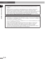
The following shall be described in the Copyright section and the description shall not be
changed without permission.
OMRON, 2010 All rights reserved. No part of this publication may be reproduced, stored in a
retrieval system, or transmitted, in any form, or by any means, mechanical, electronic,
photocopying, recording, or otherwise, without the prior written permission of OMRON.
No patent liability is assumed with respect to the use of the information contained herein.
Moreover, because OMRON is constantly striving to improve its high-quality products,
the information contained in this manual is subject to change without notice. Every
precaution has been taken in the preparation of this manual. Nevertheless, OMRON
assumes no responsibility for errors or omissions. Neither is any liability assumed for
damages resulting from the use of the information contained in this publication.
INTRODUCTION
Our thanks for your purchase of this Ethernet unit for use with OMRON YRC series robot controllers.
This is an optional unit to allow connecting OMRON YRC series robot controllers to the widely
used Ethernet which is the standard factor for office equipment network.
This manual describes typical examples for taking safety measures, installing wiring, making
machine settings and operating the machine to ensure that the Ethernet unit is used safely and
effectively. Be sure to read this manual before use. Even after reading this manual, keep it in a
safe, easily accessible location so it can be referred to whenever needed. When moving this unit,
always make sure this manual accompanies it, and make sure that the person who will actually use
this Ethernet unit reads this manual thoroughly.
This manual only contains information involving the Ethernet unit. Please refer to the controller
user's manual and programming manual for information on basic robot controller operation and
programming.
DISCLAIMERS
CHANGE IN SPECIFICATIONS
Product specifications and accessories may be changed at any time based on improvements and other reasons. It is our practice
to change model numbers when published ratings or features are changed, or when significant construction changes are made.
However, some specifications of the products may be changed without any notice. When in doubt, special model numbers
may be assigned to fix or establish key specifications for your application on your request. Please consult with your OMRON
representative at any time to confirm actual specifications of purchased products.
DIMENSIONS AND WEIGHTS
Dimensions and weights are nominal and are not to be used for manufacturing purposes, even when tolerances are shown.
PERFORMANCE DATA
Performance data given in this manual is provided as a guide for the user in determining suitability and does not constitute
a warranty. It may represent the result of OMRON’s test conditions, and the users must correlate it to actual application
requirements. Actual performance is subject to the OMRON Warranty and Limitations of Liability.
ERRORS AND OMISSIONS
The information in this manual has been carefully checked and is believed to be accurate; however, no responsibility is
assumed for clerical, typographical, or proofreading errors, or omissions.
General Contents
Chapter 1 Cautions To Ensure Safety................................................................................. 1-1
1-1
1-2
1-3
1-4
1-5
1-6
Basic safety points................................................................................................................. 1-2
System design safety points.................................................................................................. 1-2
Installation and wiring safety points................................................................................... 1-3
Start-up and maintenance safety points............................................................................. 1-4
Precautions when disposing of the unit.............................................................................. 1-4
Warranty............................................................................................................................... 1-5
Chapter 2 Ethernet Unit....................................................................................................... 2-1
2-1
2-2
2-3
2-4
Ethernet unit features.......................................................................................................... 2-2
How data is exchanged......................................................................................................... 2-3
How to connect to Ethernet................................................................................................. 2-4
Making system settings for the controller (server)............................................................ 2-5
2-4-1
2-4-2
2-4-3
2-4-4
Validating the Ethernet unit...................................................................................................... 2-5
Setting the IP address............................................................................................................... 2-6
Setting the subnet mask............................................................................................................ 2-8
Setting the gateway.................................................................................................................. 2-9
2-5 Making the PC settings (client)......................................................................................... 2-10
2-5-1
Setting the TCP/IP protocol.................................................................................................... 2-10
2-6 Checking the connection with "ping"............................................................................... 2-12
2-7 Using TELNET................................................................................................................... 2-13
2-7-1
Difference between TELNET and RS-232C communications.............................................. 2-13
2-8 TELNET dedicated parameters........................................................................................ 2-14
2-8-1
2-8-2
Parameter description............................................................................................................. 2-14
Setting the parameters............................................................................................................ 2-17
2-9 TELENET communication commands............................................................................ 2-18
2-9-1
2-9-2
2-9-3
Communication command specifications............................................................................... 2-18
Ethernet unit control commands............................................................................................ 2-19
Robot control commands....................................................................................................... 2-19
2-10 Making a connection with TELNET.EXE........................................................................ 2-20
2-11 Other operating tasks......................................................................................................... 2-22
2-11-1 Displaying the MAC address................................................................................................. 2-22
2-11-2 Displaying the version of the Ethernet unit............................................................................ 2-23
2-12 Message List........................................................................................................................ 2-24
2-12-1 Error messages....................................................................................................................... 2-24
2-12-2 Telnet message list.................................................................................................................. 2-25
2-13 Troubleshooting.................................................................................................................. 2-26
2-14 Specifications....................................................................................................................... 2-29
2-14-1 Ethernet unit specifications.................................................................................................... 2-29
2-14-2 Modular connector................................................................................................................. 2-30
2-14-3 UTP (STP) cable.................................................................................................................... 2-31
2-15 Supplement.......................................................................................................................... 2-32
2-15-1 Typical network systems........................................................................................................ 2-32
2-15-2 Description of terminology ................................................................................................... 2-36
v
Chapter 1
Cautions To Ensure Safety
1
Cautions To Ensure Safety
1-1
1-1 Basic safety points
1-1
1
Basic safety points
Cautions To Ensure Safety
Besides reading this manual and the controller user's manual, also be sure to handle the equipment
correctly while paying sufficient attention to safety.
Points regarding safety in this manual only list items involving this product. Please refer to the
controller user's manual for information regarding safety when using this unit with the controller.
It is not possible to detail all safety items within the limited space of this manual. So it is essential
that the user have a full knowledge of basic safety rules and also that the operator makes correct
judgments on safety procedures during operation.
Industrial robots are highly programmable, mechanical devices that provide a large degree of
freedom when performing various manipulative tasks. Failure to take necessary safety measures or
mishandling due to not following the instruction in this manual may result in trouble or damage to
the robot and injury to personnel (robot operator or service personnel) including fatal accidents.
Important caution points in this manual are from hereon indicated by the term:
CAUTION
1-2
System design safety points
CAUTION
ETHERNET COMMUNICATIONS PROTOCOL SPECIFICATIONS DO NOT GUARANTEE REAL-TIME
OPERATION. SO RELYING ONLY ON THE ETHERNET IN SITUATIONS SUCH AS ROBOT EMERGENCY
STOP CAN BE EXTREMELY DANGEROUS. INSTALL SAFETY INTERLOCK CIRCUITS USING THE
EMERGENCY STOP TERMINAL IN THE SAFETY CONNECTOR OF THE ROBOT CONTROLLER TO
ENSURE QUICK AND EFFECTIVE EMERGENCY STOPS.
CAUTION
TO FIND THE CURRENT STATUS OF THE NETWORK SYSTEM AND ROBOT CONTROLLER WHEN
COMMUNICATION ERRORS OCCUR ON THE ETHERNET SYSTEM, REFER BEFOREHAND TO THIS
MANUAL AND THE INSTRUCTION MANUAL FOR EQUIPMENT USED BY THE OTHER PARTY. ALSO
INSTALL SAFETY INTERLOCK CIRCUIT SO THAT SYSTEMS INCLUDING A ROBOT CONTROLLER
WILL FUNCTION RELIABLY AND SAFELY WHEN COMMUNICATION ERRORS OCCUR.
CAUTION
DO NOT BUNDLE CONTROL LINES OR COMMUNICATION CABLES TOGETHER OR IN CLOSE CONTACT WITH MAIN CIRCUIT OR MOTOR/ACTUATOR LINES. AS A GENERAL RULE, MAINTAIN A
GAP OF AT LEAST 100MM. NOISE IN SIGNAL LINES MAY CAUSE FAULTY OPERATION.
1-2
1-3 Installation and wiring safety points
1-3
Installation and wiring safety points
1
CAUTION
ALWAYS USES THE SYSTEM SPECIFICATIONS AS LISTED IN THE CONTROLLER USER’S MANUAL
DURING INSTALLATION OR WIRING WORK ON THE ROBOT CONTROLLER. ATTEMPTING TO USE
OTHER THAN THESE SYSTEM SPECIFICATIONS MIGHT CAUSE ELECTRICAL SHOCKS, FIRE, FAULTY
OPERATION, PRODUCT DAMAGE OR DETERIORATED PERFORMANCE.
CAUTION
SECURELY INSTALL THE CONNECTORS INTO THE UNIT, AND WHEN WIRING THE CONNECTORS,
MAKE THE CRIMP, CONTACT OR SOLDER CONNECTIONS CORRECTLY, USING THE TOOL SPECIFIED
BY THE MANUFACTURER. POOR CONNECTIONS WILL CAUSE FAULTY OPERATION.
CAUTION
WHEN INSTALLING THE UNIT, BE CAREFUL NOT TO DIRECTLY TOUCH ANY ELECTRONIC COMPONENTS (EXCEPT DIP SWITCHES) OR PARTS CONDUCTING ELECTRICAL CURRENT.
CAUTION
MAKE SURE THAT FOREIGN MATTER SUCH AS WIRING DEBRIS OR DUST DOES NOT PENETRATE
INTO THE ROBOT CONTROLLER.
CAUTION
ALWAYS STORE NETWORK CABLE INSIDE CABLE DUCTS OR CLAMP THEM SECURELY IN PLACE.
OTHERWISE, EXCESSIVE PLAY OR MOVEMENT, OR MISTAKENLY PULLING ON THE CABLE MAY
DAMAGE THE UNIT OR CABLES, OR POOR CABLE CONTACT MAY LEAD TO FAULTY OPERATION.
CAUTION
WHEN DETACHING THE CABLE, REMOVE BY HOLDING THE CONNECTOR ITSELF AND NOT BY
TUGGING ON THE CABLE. OTHERWISE, REMOVING BY PULLING ON THE CABLE ITSELF MAY DAMAGE THE UNIT OR CABLES, OR POOR CABLE CONTACT MAY LEAD TO FAULTY OPERATION.
1-3
Cautions To Ensure Safety
CAUTION
ALWAYS CUT OFF ALL POWER TO THE CONTROLLER AND THE OVERALL SYSTEM BEFORE ATTEMPTING INSTALLATION OR WIRING JOBS. THIS WILL PREVENT POSSIBLE ELECTRICAL SHOCKS.
AFTER THE CONTROLLER HAS BEEN ON FOR A WHILE, SOME POINTS IN THE CONTROLLER MAY
BE EXTREMELY HOT OR REMAIN AT HIGH VOLTAGES. AFTER CUTTING OFF THE POWER WHEN
INSTALLING OR REMOVING THE UNIT, WAIT AT LEAST 5 MINUTES BEFORE STARTING WORK.
1-4 Start-up and maintenance safety points
1-4
1
Start-up and maintenance safety points
Cautions To Ensure Safety
CAUTION
NEVER ATTEMPT TO DISASSEMBLE THE ROBOT OR CONTROLLER. WHEN A ROBOT OR CONTROLLER COMPONENT MUST BE REPAIRED OR REPLACED, CONTACT US FOR DETAILS ON
HOW TO PERFORM THE SERVICING.
CAUTION
ALWAYS CUT OFF ALL POWER TO THE CONTROLLER AND THE OVERALL SYSTEM BEFORE ATTEMPTING MAINTENANCE OR SERVICING. THIS WILL PREVENT POSSIBLE ELECTRICAL
SHOCKS.
AFTER THE CONTROLLER HAS BEEN ON FOR A WHILE, SOME POINTS IN THE CONTROLLER MAY
BE EXTREMELY HOT OR REMAIN AT HIGH VOLTAGES. AFTER CUTTING OFF THE POWER WHEN
INSTALLING OR REMOVING THE UNIT, WAIT AT LEAST 5 MINUTES BEFORE STARTING WORK.
CAUTION
DO NOT TOUCH THE TERMINALS (OR PINS) WHILE POWER IS STILL APPLIED TO THE UNIT. THIS
MAY CAUSE ELECTRICAL SHOCKS OR FAULTY OPERATION.
1-5
Precautions when disposing of the unit
CAUTION
THIS PRODUCT MUST BE PROPERLY HANDLED AS INDUSTRIAL WASTE WHEN ITS DISPOSAL IS
REQUIRED.
1-4
1-6 Warranty
1-6
Warranty
Warranty description
: If a failure or breakdown occurs due to defects in materials or
workmanship in the genuine parts constituting this OMRON
robot and/or related product within the warranty period, then
OMRON shall supply free of charge the necessary replacement/repair parts.
Warranty Period
: The warranty period ends 24 months after the date of manufacturing as shown on the products.
Exceptions to the Warranty
: This warranty will not apply in the following cases:
(1)Fatigue arising due to the passage of time, natural wear
and tear occurring during operation (natural fading of
painted or plated surfaces, deterioration of parts subject to
wear, etc.)
(2)Minor natural phenomena that do not affect the capabilities of the robot and/or related product (noise from
computers, motors, etc.).
(3)Programs, point data and other internal data that were
changed or created by the user.
Failures resulting from the following causes are not covered by warranty.
1) Damage due to earthquakes, storms, floods, thunderbolt, fire or any other natural or manmade disasters.
2) Troubles caused by procedures prohibited in this manual.
3) Modifications to the robot and/or related product not approved by OMRON or OMRON
sales representatives.
4) Use of any other than genuine parts and specified grease and lubricants.
5) Incorrect or inadequate maintenance and inspection.
6) Repairs by other than authorized dealers.
1-5
1
Cautions To Ensure Safety
The OMRON robot and/or related product you have purchased are warranted against the defects or
malfunctions as described below.
1-6 Warranty
1
Cautions To Ensure Safety
WARRANTY
OMRON’s exclusive warranty is that the products are free from defects in materials and
workmanship for a period of one year (or other period if specified) from date of sale by
OMRON.
OMRON MAKES NO WARRANTY OR REPRESENTATION, EXPRESS OR IMPLIED,
REGARDING NONINFRINGEMENT, MERCHANTABILITY, OR FITNESS FOR
PARTICULAR PURPOSE OF THE PRODUCTS. ANY BUYER OR USER ACKNOWLEDGES
THAT THE BUYER OR USER ALONE HAS DETERMINED THAT THE PRODUCTS
WILL SUITABLY MEET THE REQUIREMENTS OF THEIR INTENDED USE. OMRON
DISCLAIMS ALL OTHER WARRANTIES, EXPRESS OR IMPLIED.
LIMITATIONS OF LIABILITY
OMRON SHALL NOT BE RESPONSIBLE FOR SPECIAL, INDIRECT, OR CONSEQUENTIAL
DAMAGES, LOSS OF PROFITS OR COMMERCIAL LOSS IN ANY WAY CONNECTED WITH
THE PRODUCTS, WHETHER SUCH CLAIM IS BASED ON CONTRACT, WARRANTY,
NEGLIGENCE, OR STRICT LIABILITY.
In no event shall the responsibility of OMRON for any act exceed the individual price of the
product on which liability is asserted.
IN NO EVENT SHALL OMRON BE RESPONSIBLE FOR WARRANTY, REPAIR, OR
OTHER CLAIMS REGARDING THE PRODUCTS UNLESS OMRON’S ANALYSIS
CONFIRMS THAT THE PRODUCTS WERE PROPERLY HANDLED, STORED,
INSTALLED, AND MAINTAINED AND NOT SUBJECT TO CONTAMINATION, ABUSE,
MISUSE, OR INAPPROPRIATE MODIFICATION OR REPAIR.
1-6
Chapter 2
Ethernet Unit
2
Ethernet Unit
2-1
2-1 Ethernet unit features
2-1
Ethernet unit features
Ethernet is the network most commonly used by office equipment today. This Ethernet unit is an
optional device for connecting to OMRON robot controller over the Ethernet.
The communications protocol utilizes TCP/IP which is a standard Internet protocol so PCs and
business computers with Internet access or equipment incorporating TCP/IP protocols can easily
exchange data with the robot controller.
Ethernet Unit
2
Main features of this Ethernet unit for YRC series robot controllers are as follows:
■ The YRC series robot controllers can be connected to the Ethernet system using this unit.
The unit fits directly inside the controller and so does not require any extra installation
space.
■ The Ethernet unit uses 10BASE-T specifications, so UTP cables (unshielded twisted-pair
cables) or STP cables (shielded twisted-pair cables) can be used. This makes cable and
wiring installation really easy.
■ Several controllers can be connected on the same network so information can be processed
in one batch from a designated PC.
■ Utilizing a HUB having 10BASE-2 or 10BASE-5 connectors, robot controllers can be accessed even from offices located away from the factory. Using the Internet allows accessing
even robot controllers in remote locations.
■ The robot controller operates as a TELNET (socket) server, which can easily be accessed
from PCs used as TELNET terminals. (Windows PCs incorporate a TELNET terminal called
TELNET.EXE as standard equipment.)
Ethernet unit commands are the same as those handled through RS-232C, so even first-time
users will find it easy to use.
If information such as network settings on the PC or for detailed information on other equipment is
needed, refer to that particular user's manual or product instruction manual.
For information on operating the OMRON robot controller and robot programming, refer to the
controller user's manual and programming manual.
* Ethernet is a registered trademark of the Xerox Corporation (USA).
2-2
2-2 How data is exchanged
2-2
How data is exchanged
The following is a brief explanation to help understand how information is exchanged over the
Ethernet with the other devices, such as between the robot controller and PC.
The YRC series robot controllers equipped with the Ethernet unit operate as a server and
constantly await a connection request from the client (other party's device such as a PC). Specificactions are then carried out when a request arrives from a client. So the robot controller
does not connect to another server on its own.
192.168.0.5
YRC
robot controller
+
Ethernet Unit
IP address
192.168.0.3
Server
Functions as a server.
Performs specified
actions upon receiving
request from client.
Ethernet
2
1
Client
192.168.0.10
Client
192.168.0.11
Client
192.168.0.12
Device such as PC is the client, connects to server and issues commands to perform
specified actions.
1- Specify the IP address of robot controller to exchange data with and make the connection.
(Above example shows the client 192.168.0.10 has specified the robot controller 192.168.0.5
and made a connection.)
2- After making the connection, the robot controller runs a specific series of actions according
to instructions from the client.
NOTE
During multitasking by the client, several robots can be simultaneously connected to one client unit.
Only one client can make a simultaneous connection to one robot controller unit.
Settings such as of the IP address and subnet are made from the PB.
2-3
2
Ethernet Unit
In the communications method called TCP/IP, an IP address is assigned to each device connected
on the network. The IP address is a number unique to each device and serves to identify that
device. In the communications process, the IP address of the robot controller must first be specified
to make connection. After making the connection, the actual data is exchanged between the devices
and when finished the connection is terminated.
2-3 How to connect to Ethernet
2-3
How to connect to Ethernet
The Ethernet unit for YRC series employs 10BASE-T specifications, so the robot controller connects by a cable to the HUB.
Use UTP cables (unshielded twisted-pair cables) or STP cables (shielded twisted-pair cables) for
category 3 or higher, with straight-through wiring specifications.
To connect to the Ethernet, insert the cable with modular jack into the modular connector on the
controller until you hear a click. Insert the other end of the cable into the modular connector on the
HUB.
Ethernet Unit
2
Fig. 2-1 Connecting to Ethernet
HUB
1
2
3
4
5
6
7
8
MOTOR
OP.1
OP.3
OP.2
OP.4
PWR
SRV
XM
YRC
PB
ERR
ROB
I/O
XY
UTP (STP)
straight-through cable
YM
BATT
XY
SE L
COM
ROB
I/O
ZR
ZM
BATT
ZR
STD.DIO
SAFET Y
RGEN
P
N
ACIN
L
RM
N
L1
N1
EX T.E-S TOP
13 14
YRC robot controller
CAUTION
WE USE AN FL HUB (MADE BY PHOENIX CONTACT) TO CHECK OPERATION. USING THIS HUB IS
RECOMMENDED IF CONSTRUCTING YOUR OWN SYSTEM.
HUBS GENERALLY AVAILABLE ON THE MARKET ARE NOT DESIGNED FOR USE IN LOCATIONS
SUCH AS FACTORIES, SO SOME HUBS ARE VULNERABLE TO EXTERNAL NOISE. PLEASE ACKNOWLEDGE BEFOREHAND THAT OPERATION CANNOT BE GUARANTEED IF OTHER TYPES OF
HUBS ARE USED.
ALWAYS BE SURE TO USE A HUB WITH HIGH NOISE RESISTANCE WHEN CONNECTING TO THE
CONTROLLER.
CAUTION
THE MAXIMUM CABLE LENGTH BETWEEN THE HUB AND CONTROLLER IS 100 METERS.
BEFORE CONNECTING THE HUB AND CONTROLLER ALWAYS REFER TO THE INSTRUCTION MANUALS FOR THE DEVICE USED BY THE OTHER PARTY AND PERIPHERAL EQUIPMENT SUCH AS
THE HUB.
IF THE HUB COMMUNICATION MODE CAN BE SET MANUALLY, THEN SET TO 10MBPS/HALF DUPLEX.
NOTE
Using a straight-through cable is recommended when connecting to the other party's device by way of the HUB.
You can connect directly to the other party's device without the HUB by using a crossover cable but communication
may sometimes not be possible due to the type of LAN adapter used by other party's device.
2-4
2-4 Making system settings for the controller (server)
2-4
Making system settings for the controller (server)
A minimum of IP address, subnet mask and gateway settings must be made so that the robot
controller will be correctly identified and acknowledged on Ethernet.
These settings are made from the PB. The following sections explain the procedures using the PB.
The settings will be enabled after restarting the controller.
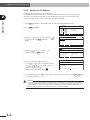
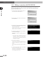
To use the Ethernet, the Ethernet board must first be enabled by setting the parameter.
1) Press F1 (PARAM) in "SYSTEM" mode to enter "SYSTEM>PARAM" mode.
2) Press F5 (OP. BRD).
3) Select the number for "E_Net" with the
keys and press F1 (SELECT).
•
SYSTM > PARAM
Robot = R6YXH250
M1 =a R6YXH250
M2 =a R6YXH250
M3 =a R6YXH250
M4 =a R6YXH250
ROBOT
AXIS
v1.23M
SSS=+
SSSSSS
M5 = noaxis
M6 = noaxis
OTHERS
OP. BRD
v 1.23M
SYSTM>PARAM>OP.BRD V8.01
1.E_Net
2. ーーー
3. ーーー
4. ーーー
SELECT
4) The current Ethernet unit identity status
appears on the display.
With the cursor positioned on the “1. board
condition” press F1 (EDIT).
5) Press F2 (VALID) to make the Ethernet
identifiable from the controller.
If making it unidentified from the controller,
press F1 (INVALID).
v 1.23M
SYSTM>PARAM>OP.BRD V8.01
1.board condition VALID
2.IP address 192.168. 0. 2 3.subnet mask 255.255.255. 0
4.gateway 192.168. 0. 1
5.port No 23
EDIT JUMP
SYSTM>PARAM>OP.BRD V8.01
v 1.23M
1.board condition VALID
2.IP address 192.168. 0. 2 3.subnet mask 255.255.255. 0
4.gateway 192.168. 0. 1
5.port No 23
INVALID VALID
6) To end the setting, press ESC . To continue setting another parameter, use the
to select the parameter.
keys
2-5
Ethernet Unit
2-4-1 Validating the Ethernet unit
2
2-4 Making system settings for the controller (server)
2-4-2 Setting the IP address
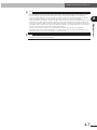
The following explains how to set the IP address.
The IP address is a number unique to each device and identifies that device from among many other devices connected on the network. The IP address of one device must not be the same number as another device so use caution when setting the IP address.
Ethernet Unit
2
1) Press F1 (PARAM) in "SYSTEM" mode to enter "SYSTEM>PARAM" mode.
•
2) Press F5 (OP. BRD).
3) Select the number for "E_Net" with the
keys and press F1 (SELECT).
SYSTM > PARAM
Robot = R6YXH250
M1 =a R6YXH250
M2 =a R6YXH250
M3 =a R6YXH250
M4 =a R6YXH250
ROBOT
AXIS
v1.23M
M5 = noaxis
M6 = noaxis
OTHERS
OP. BRD
v 1.23M
SYSTM>PARAM>OP.BRD V8.01
1.E_Net
2. ーーー
3. ーーー
4. ーーー
SELECT
v 1.23M
SYSTM>PARAM>OP.BRD V8.01
4) Press the
key once to select "2. IP
address" and press F1 (EDIT).
5) The currently set IP address appears.
To change it, enter the new IP address with
the 0 to 9 keys. Enter the exact
number including periods (.).
After changing the setting, press
.
1.board condition VALID
2.IP address 192.168. 0. 2 3.subnet mask 255.255.255. 0
4.gateway 192.168. 0. 1
5.port No 23
EDIT JUMP
v 1.23M
SYSTM>PARAM>OP.BRD V8.01
1.board condition VALID
2.IP address 192.168. 0. 2 3.subnet mask 255.255.255. 0
4.gateway 192.168. 0. 1
5.port No 23
Enter IP address >192.168. 0. 2
6) To end the setting, press ESC . To continue setting another parameter, use the
to select the parameter.
keys
CAUTION
ALL CHANGES TO THE IP ADDRESS, SUBNET MASK AND GATEWAY SETTINGS WILL BE ENABLED
AFTER RESTARTING THE ROBOT CONTROLLER. WHEN CONNECTING THE ROBOT CONTROLLER
ON AN ALREADY EXISTING NETWORK, ALWAYS CHECK WITH THE NETWORK SUPERVISOR BEFORE MAKING IP ADDRESS, SUBNET MASK AND GATEWAY SETTINGS.
2-6
2-4 Making system settings for the controller (server)
NOTE
The Ethernet unit for YRC series is not usable with IP address auto acquisition functions such as DHCP and
BOOTP. You must set the IP address manually.
2-7
2
Ethernet Unit
NOTE
The IP address is separated into network address and host address sections. The network address section is extracted
from the IP address by AND processing with the subnet mask. The remaining portion is the host address section.
Devices belonging to the same network must all be set to have the same network address. The host address, however, should be different for every device and set so that no two devices have the same number. The first and
the last host address numbers are reserved for the system so be sure not to set these as the IP address.
When the IP address for example is 192.168.0.10 and the subnet mask is 255.255.255.0, the network address section
is found to be 192.168.0 and the host address section to be 10 by means of AND processing with the subnet mask.
In this case, the network address section of all other devices belonging to that network must all be 192.168.0. The
host address section of those other devices on the other hand, must be set to a number other than 10. The number 0
and 255 are reserved, so do not use them for setting the host address.
So when a device having an IP address of 192.168.0.10 and a subnet mask of 255.255.255.0 belongs to a particular network and you want to add another device to that network, then you would assign IP addresses from
among 192.168.0.1 to 192.168.0.9 and 192.168.0.11 to 192.168.0.254.
2-4 Making system settings for the controller (server)
2-4-3 Setting the subnet mask
The following explains how to set the subnet mask.
The subnet mask is a numerical address used to subdivide the network into smaller parts.
2
Ethernet Unit
1) Press F1 (PARAM) in "SYSTEM" mode to enter "SYSTEM>PARAM" mode.
2) Press F5 (OP. BRD).
•
3) Select the number for "E_Net" with the
keys and press F1 (SELECT).
SYSTM > PARAM
Robot = R6YXH250
M1 =a R6YXH250
M2 =a R6YXH250
M3 =a R6YXH250
M4 =a R6YXH250
ROBOT
AXIS
v1.23M
M5 = noaxis
M6 = noaxis
OTHERS
OP. BRD
v 1.23M
SYSTM>PARAM>OP.BRD V8.01
1.E_Net
2. ーーー
3. ーーー
4. ーーー
SELECT
key twice to select "3. subnet
4) Press the
mask" and then press F1 (EDIT).
5) The currently set subnet mask appears.
To change it, enter the new subnet mask with
the 0 to 9 keys. Enter the exact
number including periods (.).
After changing the setting, press
.
SYSTM>PARAM>OP.BRD V8.01
v 1.23M
1.board condition VALID
2.IP address 192.168. 0. 2 3.subnet mask 255.255.255. 0
4.gateway 192.168. 0. 1
5.port No 23
EDIT JUMP
v 1.23M
SYSTM>PARAM>OP.BRD V8.01
1.board condition VALID
2.IP address 192.168. 0. 2 3.subnet mask 255.255.255. 0
4.gateway 192.168. 0. 1
5.port No 23
Enter subnet mask >255.255.255. 0
6) To end the setting, press ESC . To continue setting another parameter, use the
to select the parameter.
2-8
keys
2-4 Making system settings for the controller (server)
2-4-4 Setting the gateway
The following explains how to set the gateway. Basically this is specifying the router IP address.
The router is a device relaying information from a certain network to a different network when two
or more networks are present.
2
1) Press F1 (PARAM) in "SYSTEM" mode to enter "SYSTEM>PARAM" mode.
3) Select the number for "E_Net" with the
keys and press F1 (SELECT).
SYSTM > PARAM
Robot = R6YXH250
M1 =a R6YXH250
M2 =a R6YXH250
M3 =a R6YXH250
M4 =a R6YXH250
ROBOT
AXIS
v1.23M
M5 = noaxis
M6 = noaxis
OTHERS
OP. BRD
SYSTM>PARAM>OP.BRD V8.01
v 1.23M
1.E_Net
2. ーーー
3. ーーー
4. ーーー
SELECT
4) Press the
key three times to select "4.
gateway " and then press F1 (EDIT).
v 1.23M
SYSTM>PARAM>OP.BRD V8.01
5) The currently set gateway appears.
To change it, enter the new gateway with the
0 to 9 keys. Enter the exact number including periods (.).
SYSTM>PARAM>OP.BRD V8.01
v 1.23M
After changing the setting, press
.
1.board condition VALID
2.IP address 192.168. 0. 2 3.subnet mask 255.255.255. 0
4.gateway 192.168. 0. 1
5.port No 23
EDIT JUMP
1.board condition VALID
2.IP address 192.168. 0. 2 3.subnet mask 255.255.255. 0
4.gateway 192.168. 0. 1
5.port No 23
Enter gateway >192.168. 0. 1
6) To end the setting, press ESC . To continue setting another parameter, use the
to select the parameter.
keys
CAUTION
ANY APPROPRIATE GATEWAY ADDRESS CAN BE USED AS LONG AS THE NETWORK IS NOT CONNECTED TO OTHER NETWORKS. (HOWEVER, USE AN IP ADDRESS THAT HAS NOT YET BEEN ASSIGNED TO OTHER DEVICES.)
WHEN CONNECTING THE ROBOT CONTROLLER ON AN ALREADY EXISTING NETWORK, ALWAYS
CHECK WITH THE NETWORK SUPERVISOR BEFORE MAKING IP ADDRESS, SUBNET MASK AND
GATEWAY SETTINGS.
THE ETHERNET UNIT FOR YRC SERIES USES A PRIVATE ADDRESS AS THE IP ADDRESS DEFAULT
SETTING. THIS DEFAULT VALUE CANNOT BE USED AS IS ON THE INTERNET. SO WHEN CONNECTING TO THE INTERNET, ALWAYS BE SURE TO CHANGE THE IP ADDRESS OF THE ROBOT
CONTROLLER TO A GLOBAL ADDRESS.
2-9
Ethernet Unit
•
2) Press F5 (OP. BRD).
2-5 Making the PC settings (client)
2-5
Making the PC settings (client)
The settings for the device (PC) are also essential for correctly exchanging information with the
robot controller. A basic method for setting a computer using Windows XP is described below. If
using a device having a different OS (operating system) or TCP/IP protocols, refer to the user's
manual for that device for information on how to make the settings.
2
Ethernet Unit
* Windows is a registered trademark of the Microsoft Corporation (USA).
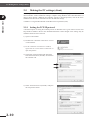
2-5-1 Setting the TCP/IP protocol
A brief description of setting the TCP/IP protocol for Windows XP is given below. See the First
Step Guide in Windows XP for more detailed information. Some changes in the settings may be
needed to match the user's network.
1) Open "Control Panel".
2) Double-click "Network connections" icon in
"Control Panel".
3) In the "Network connection" window, right-click on "Local Area Connection" to
open "Properties".
4) Check that "Client for Microsoft Networks"
and "Internet Protocol (TCP/IP)" are listed on
the "General" tab.
5) Select "Internet Protocol (TCP/IP)" and press
the "Properties" button.
2-10
2-5 Making the PC settings (client)
6) In the "Internet Protocol (TCP/IP) Properties"
dialog box, set the PC's IP address, subnet
mask, and gateway to match the status of use.
Also set the DNS server to match the status of
use.
2
Ethernet Unit
7) Click OK to close the setup screen.
2-11
2-6 Checking the connection with "ping"
2
Once you are finished with the network settings, make a check with "ping" to confirm that you can
send and receive data normally. Here, "ping" is a network diagnostic tool incorporated into the OS
as a standard feature. A simple description of how to use "ping" incorporated into Windows XP is
described below so refer to it when needed. If using "ping" while incorporated into another OS or
TCP/IP protocol, then consult the instruction manual for that particular device.
Ethernet Unit
2-6 Checking the connection with "ping"
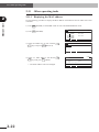
1) Click the "Start" button, point to "All Programs", and select "Accessories" ``"Command Prompt" to open the "Command
Prompt" screen.
2) Run the ping command.
Following the command prompt ">", enter
"ping xxx.xxx.xxx.xxx" and press the Enter
key.
In the "ping xxx.xxx.xxx.xxx" portion, enter
the IP address of the robot controller.
3) The screen on the right shows an example
that normal communication is established.
4) The screen on the right shows an example that
normal communication is not established. If
this happens, recheck the network device and
settings, and eliminate the trouble.
2-12
2-7 Using TELNET
2-7
Using TELNET
Communicating by TELNET (remote operation) allows loading and editing point or program data
and operating the robot just the same if connected through an RS-232C port.
Commands are easy to understand because they are identical to RS-232C communication commands.
TELNET and RS-232C both perform the same processing. However, they use different communication formats. This means that one format might not match your own particular system
needs or objectives, so you should get a good understanding of their different features before incorporating them into your system.
TELNET
• Easily connects to different types of systems. Can handle one versus multiple device communications.
• Allows remote communications since it connects between separate systems.
• Basically not usable for real-time processing since real-time operation is not guaranteed.
RS-232C
• Basically handles one party to one party (or device) communications.
• Designed for communications between devices in close proximity.
• Operates largely to real-time specifications.
Ethernet communications protocol specifications do not guarantee real-time operation. So
relying only on the Ethernet in situations such as robot emergency stop can be extremely
dangerous. Install safety interlock circuits using the emergency stop terminal in the
SAFETY connector of the robot controller to ensure quick and effective emergency stops.
2-13
Ethernet Unit
2-7-1 Difference between TELNET and RS-232C communications
2
2-8 TELNET dedicated parameters
2-8
TELNET dedicated parameters
To ensure reliable TELNET communications that match customer system settings, the Ethernet
unit for YRC series can be used with TELNET dedicated parameters explained in this section.
2
2-8-1 Parameter description
Ethernet Unit
To use TELNET communications, the following parameters should be set as needed.
Each parameter can be set in "SYSTEM > PARAM > OP. BRD" mode. See "2-8-2 Setting the parameters" for how to set the parameters.
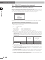
■ TCP port No.
Use this parameter to set the TCP port No. of the robot controller.
The port No. set here is specified along with the IP address when the client connects to the robot
controller.
PB display
5. port No
Input range
0 to 65535
Default value
23 (TELNET port)
* If any value other than the TELNET port (23) is specified, then negotiation with the TELNET protocol is not attempted. (Switches to ordinary socket communication.)
* Using a port No. other than the well-known ports (0 to 1023) is advised when changing the
port.
* After changing the setting, restart the controller to enable the change.
■ Echoback
Use this parameter to select whether or not to send back (echoback) to the client, the same characters that the client sent to the robot controller.
PB display
6. echoback
Input range
F1
F2
Default value
Valid
: Invalid
: Valid
■ Communication timeout
The TELNET connection can be disconnected if data is not sent or received from the client or
robot controller within a certain amount of time.
Use this parameter to set the amount of that time (minutes). Setting to "0" (zero) voids the timeout check and there is no timeout to disconnect the TELNET connection.
PB display
Input range
Default value
2-14
7. timeout [min]
0 to 255 (minutes)
10
2-8 TELNET dedicated parameters
PB display
8. login check
Input range
F1
F2
Default value
Valid
: Invalid
: Valid
■ LOGIN user name
Use this parameter to set the login user name.
When the login check is enabled, the client must enter the user name specified here to connect
to the robot controller.
PB display
9. login user
1 to 8 characters
<Usable characters>
Alphabets
Input range
: A to Z
Numbers
: 0 to 9
Symbols
: ! " # $ % & ' ( ) + = . : ; – ? @ | { } _ ~
< > * , ^ [ ] /
Default value
USER
■ LOGIN password
Use this parameter to set the login password.
When the login check is enabled, the client must enter the password specified here to connect to
the robot controller.
PB display
10. login password
1 to 8 characters
<Usable characters>
Input range
Alphabets
: A to Z
Numbers
: 0 to 9
Symbols
: ! " # $ % & ' ( ) + = . : ; – ? @ | { } _ ~
< > * , ^ [ ] /
Default value
PASSWORD
■ LOGOUT processing
This parameter sets whether to stop the robot automatically or to continue the robot operation
when the client disconnects from the robot controller.
PB display
Input range
Default value
11. logout
F1
: CONT. (Continues robot operation.)
F2
: Stop (Stops robot operation.)
Stop
* If TELNET connection is cut off due to an error, the robot operation stops automatically regardless of the above setting.
2-15
2
Ethernet Unit
■ LOGIN check
Use this parameter to set whether or not to perform a login check when a client attempts to connect to the robot controller.
When the login check is enabled, the user name and password are always checked when the
client attempts to connect to the robot controller. The client cannot connect the robot controller
unless the user name and password sent from the client match the data stored in the robot controller. When the login check is disabled, the client can connect to the robot controller without a login check and communication is possible right away.
2-8 TELNET dedicated parameters
■ No-response timeout
If no-response has come back from the client, packets (keep-alive packets) can be sent at fixed
time intervals to verify if the other party is present. This parameter sets the time interval between transmissions of these packets.
If no-response state continues for a specified time (setting time × 3 [Default is 15 seconds]),
then the robot controller determines that an error has occurred and automatically cuts the TELNET connection. Setting to "0" (zero) will not send keep-alive packets so the connection
with the client is not automatically cut even if no-response state continues.
Ethernet Unit
2
PB display
12. keep-alive [sec]
Input range
0 to 255 (seconds)
Default setting
5
* Depending on the network, response time may be longer and an apparent "no-response" error detected. If this happens, change the setting as needed. (Internet, etc.)
* The controller automatically sends keep-alive packets. These packets do not affect the user
transmit/receive data.
2-16
2-8 TELNET dedicated parameters
2-8-2 Setting the parameters
1) Press F1 (PARAM) in "SYSTEM" mode to enter "SYSTEM>PARAM" mode.
2) Press F5 (OP. BRD).
•
SYSTM > PARAM
Robot = R6YXH250
M1 =a R6YXH250
M2 =a R6YXH250
M3 =a R6YXH250
M4 =a R6YXH250
ROBOT
AXIS
v1.23M
M5 = noaxis
M6 = noaxis
OTHERS
OP. BRD
v 1.23M
SYSTM>PARAM>OP.BRD V8.01
1.E_Net
2. ーーー
3. ーーー
4. ーーー
SELECT
4) Use the
keys to select the parameter
to be changed, and press F1 (EDIT).
v 1.23M
SYSTM>PARAM>OP.BRD V8.01
1.board condition VALID
2.IP address 192.168. 0. 2 3.subnet mask 255.255.255. 0
4.gateway 192.168. 0. 1
5.port No 23
EDIT JUMP
5) The setting method slightly differs according
to the parameter to be changed.
<Setting method 1>
SYSTM>PARAM>OP.BRD V8.01
v 1.23M
Enter the number with the
keys and then press
0
to
9
.
Applicable parameters
5. port No
7. timeout [min]
12. keep-alive [sec]
<Setting method 2>
v 1.23M
SYSTM>PARAM>OP.BRD V8.01
Enter the desired setting with F1 or F2 .
Applicable parameters
6. echoback
8. login check
11. logout
<Setting method 3>
Enter the setting with the
A
press
to
Z
5.port No 23
6.echoback VALID 7.timeout[min] 10
8.login check VALID
9.login user USER
INVALID VALID
SYSTM>PARAM>OP.BRD V8.01
v 1.23M
0
to
9
,
and symbol keys, and then .
1.board condition VALID
2.IP address 192.168. 0. 2 3.subnet mask 255.255.255. 0
4.gateway 192.168. 0. 1
5.port No 23
[0−65535] Enter >23
8.login check VALID
9.login user USER 10.login password PASSWORD 11.logout CONT.
12.keep−alive[sec] 5
Enter login user >USER
Applicable parameters
9. login user
10. login password
6) To end the setting, press ESC . To continue setting another parameter, use the
to select the parameter.
keys
2-17
Ethernet Unit
3) Select the number for "E_Net" with the
keys and press F1 (SELECT).
2
2-9 TELENET communication commands
2-9
TELENET communication commands
2-9-1 Communication command specifications
2
Ethernet Unit
TELNET communication commands are broadly classified into two types.
One type is commands that instruct the Ethernet unit to process the command task. The other type
is robot control commands to access the robot controller and perform sophisticated processing.
These robot control commands are further subdivided into the following 5 categories.
• Ethernet unit control commands
• Robot control commands
1. Key operation
2. Utilities
3. Data handling
4. Robot language
5. Control codes
Communication command format for robot control commands except control codes is as follows.
@ [ ] <online command> [<_command option>] <termination code>
Items in brackets [ ] can be omitted.
@................ start code (=40h)
_ ................ blank
<online command>...............Refer to programming manual.
<_command option>.............Refer to programming manual.
<termination code>...............CR (=0Dh) code, or CRLF (=0Dh + 0Ah) code
■ Robot control commands begin with the start code '@' (=40h) and run when a statement
with the last line ending with the termination code, CR (=0Dh) code or CRLF (=0Dh + 0Ah)
code, is sent to the controller. As exceptions, control codes do not require a start code and
termination code.
Ethernet unit control commands do not require a start code, but the last line must end with a
termination code.
Start code
Termination code
'@' (=40h)
CR (=0Dh) code
or
CRLF (=0Dh + 0Ah) code
Ethernet unit control commands
Robot control commands
Other than control codes
Control codes
Not required
Required
Required
Required
Not required
Not required
■ One line must be within 80 characters except for the terminal code (CR (=0Dh) code or
CRLF (=0Dh + 0Ah) code).
■ A communication command is basically composed of an <online command> and an <_command option>. Depending on the command statement, no <_command option> is used or
multiple <_command options> are used.
■ The character codes used are the JIS8 unit system codes. See the controller user's manual for
the character code tables.
■ One or more space must be inserted between <online command> and <_command option>.
■ Items in <_command option> should be specified by the user. Check the description of each
communication command and enter the appropriate data.
2-18
2-9 TELENET communication commands
2-9-2 Ethernet unit control commands
These commands instruct the Ethernet unit to process the command task. Unlike the robot control
commands described later on, the Ethernet unit control commands do not require a start code '@' (=40H) at the beginning of the command.
Transmission example
: LOGOUT c/r l/f���������������������������� Terminates TELNET communication.
(2) VER
This command shows the Ethernet unit version.
Transmission example
Response example
: VER c/r l/f
: Version_1.01 c/r l/f
(3) @ETHER ECHO <echo status>
Selects the Ethernet status.
Echo status
Transmission example
Response example
: 1 signifies using echoback. 0 signifies no echoback.
: @ETHER_ECHO_0 c/r l/f ���������� Sets to "no echoback".
: OK c/r l/f
(4) @?ETHER ECHO
Reads out the echoback status.
Transmission example
Response example
: @?ETHER_ECHO_0 c/r l/f
: 0 c/r l/f ����������������������������������������� Echobackstatusis "no echoback".
OK c/r l/f
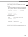
2-9-3 Robot control commands
Robot control commands access the controller and perform sophisticated processing. Command
specifications are identical to RS-232C communication commands. See the programming manual
for details on each command.
2-19
Ethernet Unit
(1) LOGOUT
BYE
This command terminates TELNET communication. The LOGOUT and the BYE commands
have the same results. Always issue one of these commands when terminating communication.
Cutting off communications without using these commands causes an errorto be issued and
halts robot operation.
2
2-10 Making a connection with TELNET.EXE
2-10 Making a connection with TELNET.EXE
A typical Windows PC has a TELNET terminal called TELNET.EXE as standard equipment. The
following briefly explains how to make a connection using TELNET.EXE. Preconditions are a robot controller IP address of 192.168.0.2, a port No. of 23, and all other dedicated TELNET parameters at their default values.
2
Ethernet Unit
1) Click the "Start" button and select "Run" to
open the file name input dialog box.
2) Enter "telnet" in the edit box and then press
the "OK" button.
3) The telnet.exe now starts up. Enter "open xxx.
xxx.xxx.xxx" following the prompt (>) and
then press the Enter key.
In the "xxx.xxx.xxx.xxx" portion, enter the IP
address of the robot controller.
4) Connection is made to the robot controller
and a login check begins.
Enter the user name here and then press the
Enter key.
* If the login check is disabled by the robot
parameter, then this user name request
message and the subsequent password
message do not appear.
5) Next, enter the password.
At this point, the password characters you
entered are displayed as asterisks (*) on the
screen.
After entering the password, press the Enter
key.
6) An OK message appears on the screen when
the login check ends normally.
From now on, commands and messages can
be exchanged with the robot.
2-20
2-10 Making a connection with TELNET.EXE
7) When the task or job is complete, enter
"LOGOUT" or "BYE" to cancel the connection with the robot controller and press
the Enter key.
2
Ethernet Unit
8) A message appears indicating the connection
has been disconnected.
Click any key to return to the screen in step 3.
9) To end the telnet.exe, enter "QUIT" following
the prompt (>) and press the Enter key.
NOTE
If you want to simultaneously control two or more robot controllers, start up TELNET.EXE as many times as
needed.
2-21
2-11 Other operating tasks
2-11 Other operating tasks
2-11-1 Displaying the MAC address
2
Ethernet Unit
Use the following procedure to display the MAC address of the Ethernet unit for YRC series robot
controllers.
1) Press F1 (PARAM) in "SYSTEM" mode to enter "SYSTEM>PARAM" mode.
2) Press F5 (OP. BRD).
3) Select the number for "E_Net" with the
keys and press F1 (SELECT).
•
SYSTM > PARAM
Robot = R6YXH250
M1 =a R6YXH250
M2 =a R6YXH250
M3 =a R6YXH250
M4 =a R6YXH250
ROBOT
AXIS
v1.23M
M5 = noaxis
M6 = noaxis
OTHERS
OP. BRD
v 1.23M
SYSTM>PARAM>OP.BRD V8.01
1.E_Net
2. ーーー
3. ーーー
4. ーーー
SELECT
4) Select "13. MAC address" with the the
keys and press F1 (EDIT).
* The MAC address cannot be changed.
2-22
v 1.23M
SYSTM>PARAM>OP.BRD V8.01
10.login password PASSWORD
11.logout CONT.
12.keep−alive[sec] 5
13.MAC address 00ー04ーC6ー01ー01ー1F
14.unit version 1.03
EDIT JUMP
2-11 Other operating tasks
2-11-2 Displaying the version of the Ethernet unit
1) Press F1 (PARAM) in "SYSTEM" mode to enter "SYSTEM>PARAM" mode.
2) Press F5 (OP. BRD).
SYSTM > PARAM
Robot = R6YXH250
M1 =a R6YXH250
M2 =a R6YXH250
M3 =a R6YXH250
M4 =a R6YXH250
ROBOT
AXIS
v1.23M
M5 = noaxis
M6 = noaxis
OTHERS
OP. BRD
SYSTM>PARAM>OP.BRD V8.01
v 1.23M
1.E_Net
2. ーーー
3. ーーー
4. ーーー
SELECT
4) Select "14. unit version" with the the
keys and press F1 (EDIT).
* The Ethernet unit version number cannot
be changed.
SYSTM>PARAM>OP.BRD V8.01
v 1.23M
10.login password PASSWORD
11.logout CONT.
12.keep−alive[sec] 5
13.MAC address 00ー04ーC6ー01ー01ー1F
14.unit version 1.03
EDIT JUMP
2-23
Ethernet Unit
3) Select the number for "E_Net" with the
keys and press F1 (SELECT).
•
2
2-12 Message List
2-12 Message List
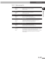
2-12-1 Error messages
2
The following error messages involving the Ethernet system have been added.
Ethernet Unit
12.41 : EtherNet link error
Code
: &H0C29
Meaning/Cause
: TELNET connection is disconnected.
a.Cable is broken or connector is disconnected.
b.Communication with the client was off for more than the time specified by the "13. timeout [min]" parameter for Ethernet.
c.Logout processing was performed because the "11. logout" parameter for Ethernet is set to "Stop".
d.There was no response from the client even when keep-alive packets were sent.
e.The LOGOUT or BYE command was not used to end the TELNET communication.
Action
: 1.Connect the cable and/or connector securely.
2.Communicate at least once within the time specified by the "7. timeout [min]" parameter, or set that parameter to "0" to disable the timeout.
3.To prevent this error at logout, set the "11. logout" parameter to "CONT.".
4.Check if the client is in response to keep-alive packets, or set the "12. keep-alive [sec]" parameter to "0" to stop sending out keep-alive packets.
5.Use the LOGOUT or BYE command to end the TELNET communication.
12.42 : EtherNet hardware error
Code
: &H0C2A
Meaning/Cause
: The Ethernet unit is broken.
Action
: Replace the Ethernet unit.
2-24
2-12 Message List
2-12-2 Telnet message list
login:
Meaning
Action
2
: Request for entry of login user name.
: Enter user name.
Meaning
Action
Ethernet Unit
Password:
: Request for entry of login password.
: Enter login password.
login incorrect:
Meaning
Action
: Error was found during login check.
: Enter the correct user name and password.
TELNET is disconnected!!
Meaning
Action
: Login check resulted in errors 3 times in succession, so connection was disconnected automatically.
: Enter the correct user name and password.
TELNET is disconnected!!
Meaning
Action
: TELNET has already been connected.
: Limit the number of simultaneous logins to 1.
timeout.
Meaning
Action
: No-communication state continued beyond the time specified
by the TELNET communication timeout parameter.
: Set the TELNET communication timeout parameter to a longer
time so that no-communication state does not exceed the timeout period.
2-25
2-13 Troubleshooting
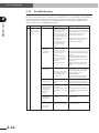
2-13 Troubleshooting
When problems occur, then troubleshoot as needed by using the following information as a guide.
Be sure to always also refer to sections on "Troubleshooting" in the controller user's manual as
well as the instruction manual for the other party's equipment such as PCs or HUB peripheral devices. If taking the troubleshooting steps listed there does not eliminate the problem, then quickly contact your local OMRON sales dealer.
Ethernet Unit
2
No.
Symptom
1
Cannot make TELNET
connection. (Using
"ping" only results in a
timeout.)
Probable causes
Checkpoints
• If timeouts still occur when connected
• Disconnect the controller
from the network and connect this way (using PC instead of controller),
then the problem is on the client side or
the PC instead. (Use a PC
capable of a good connection in the HUB peripheral device. (Check
probable causes 1 through 6.)
with the network. Make the
same IP address, subnet mask
and gateway settings as used • If a replay comes back normally, then the
problem is in the controller, so check
on the controller.)
probable causes 7 through 8.
Now try running "ping" from
the client while setup as
above, and check for a
response.
1) Ethernet cable
defects, poor
connection, or
wrong specs.
• Check if securely attached to
the modular connector.
• Check for a disconnection (or
break) in the cable or a
miswire.
• Check if the straight-through
cable or crossover cable are
being used for the wrong
connection.
• Try replacing the cables.
2) Defective HUB or
wrong settings
• Try changing to another port. • If operation returns to normal then the
port is defective, so do not use that port.
• Check if the communication • When setting the HUB communication
mode is manually set to other mode manually, then set it to
10Mbps/Half Duplex.
than 10Mbps/Half Duplex.
• If operation returns to normal then the
• Try another HUB
HUB is defective, so replace the HUB.
3) Router is defective • Check the router settings.
or wrong settings • Try substituting with another
router.
• Insert in firmly until a click noise is heard.
• Correct the wiring if a miswire is found.
Replace the cable if a break in the wiring
is found.
• Use a straight-through cable between
the HUB and controller. Use a crossover
cable if connecting directly to the other
party's device.
• If operation returns to normal, then the
problem is in the cables. Replace the
cable.
• Redo the router settings.
• If operation returns to normal then the
router is defective so replace the router.
4) Network adapter
used by the client is
defective or the
settings on the
client side are
wrong.
• Check the network settings on • Redo the network settings on the client
side.
the client side.
• Try substituting with another • If operation returns to normal then the
network adapter on the client network adapter is defective so replace
the adapter.
side.
5) Network traffic
(communication
data load) is too
heavy.
• Check if the traffic load is
appropriate.
6) Ethernet cable is
• Check how and where the
too close to a noise Ethernet cables are installed.
source such as
motor cables.
2-26
Action
• Change the network structure to get a
smaller traffic load.
• Separate the Ethernet cable from
potential noise sources.
2-13 Troubleshooting
No.
Symptom
Probable causes
Checkpoints
Action
7) Wrong IP address, • Check the settings by
• Redo the IP address, subnet mask and
referring to "2-4-2 Setting
subnet mask or
gateway settings correctly. Then turn on
gateway settings on the IP address", "2-4-3 Setting the controller power again.
the subnet mask", and "2-4-4
controller.
Setting the gateway".
2
3
• Check that the IP address of
the robot controller you are
attempting to connect with
is correct.
• Enter the correct IP address.
• Check that the port No. of
the robot controller you are
attempting to connect with
is correct.
• Enter the correct IP address.
3) Robot control is
already logged in
with another
TELNET terminal.
• When connected, the
message "telnet is already
used!" appears.
• Await termination of current TELNET
connection.
4) Alarm issued to
controller.
• Alarm message appears
when connected.
• Connect the PB and check
for an alarm.
• Status led is lit up in red.
• Troubleshoot according to the type of
alarm.
5) IP address is the
same as another
network device.
• Check if the IP address and
• If the IP address and MAC address do not
MAC address have a correct
match each other, then the IP address is
match by using the "arp"
wrong, so try redoing the settings.
command incorporated in
the OS.
• Check all devices on the
• If found to be the same as another device,
network to find if the same IP change the setting.
address is being used.
6) Network traffic
(communication
data load) is too
heavy.
• Check if the traffic load is
appropriate.
Cannot make
1) Wrong IP address
TELNET connection
used during Telnet
or cannot terminate
connection
the TELNET
connection right
2) Wrong Port No.
away. (ping reply is
used during
normal).
TELNET
connection.
An OK does not
come back after
login, or no replay
comes back even
after issuing a
command. (Some
unit control
commands are
useable such as
LOGOUT or BYE.)
• Try substituting the Ethernet • If operation returns to normal, then the
unit.
Ethernet unit is probably defective, so
replace the Ethernet unit.
1) Ethernet unit is not • See "2-4-1 Validating the
Ethernet unit" and check if
enabled and not
the Ethernet unit is enabled.
identified
(recognized) by
controller.
2) I/O custom
command input
signal is set ON.
• Change the network structure to get a
smaller traffic load.
• Enable the Ethernet unit and turn on the
power to the controller again.
• Check the I/O signal (Check
• Always use a pulse input for the custom
on the sequencer monitor,
command input.
etc.)
• Communication error is
issued when PB is connected
to controller.
3) Commands such as • Reply comes back after axis
movement or writing data.
origin return, axis
movement
commands, or data
write commands are
being run from I/O
or RS-232C.
• When issuing TELNET commands, do not
run commands from the I/O or RS-232C.
2-27
Ethernet Unit
8) Ethernet unit is
defective
2
2-13 Troubleshooting
No.
4
Ethernet Unit
2
Symptom
Probable causes
Checkpoints
Program stops by
1) TELNET
itself during
communication cuts
automatic operation.
off by itself without
a LOGOUT or BYE
command being
issued.
2) TELNET parameter
was set to stop
operation during
logout.
• Always use a LOGOUT or BYE
command to terminate a TELNET
communication.
• Check the TELNET
• Reset the parameter so operation
parameter to find if it was set continues during logout.
to stop operation during
logout.
3) Communication
• Check the TELNET
status continues for parameter to find if
a fixed period and
communication status is
then cuts off
longer than the time set for
automatically at
timeout.
timeout.
4) No-response status •
continues for a
fixed period versus
the keep-alive
•
packet and then cuts
off automatically at
timeout.
•
5) Ethernet unit is
defective.
2-28
Action
• Set so communication time does not
exceed the timeout limit. Otherwise
increase the communication timeout
period or disable the timeout function.
Check if a cable is detached • Check the network and repair/restore any
or power supply for the HUB
problem locations.
or other equipment is off.
Check if operating problems • Replace a device having operating errors
are occurring in devices such with another device.
as the HUB due to noise, etc.
Too short of a period was set • Set the no-response timeout period to
for the no-response timeout
match the network structure and traffic
period.
conditions. Or disable the timeout
function.
• Try substituting with another • If operation returns to normal, then the
Ethernet unit.
Ethernet unit is defective so replace it.
2-14 Specifications
2-14 Specifications
2-14-1 Ethernet unit specifications
Spec item
Model
2
Ethernet unit
YRC series controllers
Network specs
Conforms to Ethernet (IEEE802.3)
Baud rate
10Mbps (10BASE-T)
Connector
RJ-45 connector (octal modular connector) 1 port
Cable
UTP (unshielded twisted-pair) cable for category 3 or higher,
or STP (shielded twisted-pair) cable
Maximum cable length
100 meters (between HUB and controller)
Communication mode
Half Duplex
Network protocol
Application layer
Transport layer
Network layer
Data link layer
Physical layer
Number of simultaneous logins
IP address setting
1
From PB
Monitor LED
Run, Collision, Link, Transmit, Receive
Ethernet Unit
Applicable controllers
: TELNET
: TCP
: IP, ICMP, ARP
: CSMA/CD
: 10BASE-T
NOTE: The product external appearance and specifications are subject to change without prior
notice for purposes of improvements or other factors.
CAUTION
WE USE AN FL HUB (MADE BY PHOENIX CONTACT) TO CHECK OPERATION. USING THIS HUB IS
RECOMMENDED IF CONSTRUCTING YOUR OWN SYSTEM.
HUBS GENERALLY AVAILABLE ON THE MARKET ARE NOT DESIGNED FOR USE IN LOCATIONS
SUCH AS FACTORIES, SO SOME HUBS ARE VULNERABLE TO EXTERNAL NOISE. PLEASE ACKNOWLEDGE BEFOREHAND THAT OPERATION CANNOT BE GUARANTEED IF OTHER TYPES OF
HUBS ARE USED.
ALWAYS BE SURE TO USE A HUB WITH HIGH NOISE RESISTANCE WHEN CONNECTING TO THE
CONTROLLER.
2-29
2-14 Specifications
2-14-2 Modular connector
The pin layout for the modular connector used in the Ethernet unit for YRC series is shown below.
2
Ethernet Unit
12345678
Pin No
Signal name
1
TD+
2
TD-
3
RD+
4
N.C
5
N.C
6
RD-
7
N.C
8
N.C
* Pins 4, 5, 7, 8 are not used.
MOTOR
OP.1
OP.3
OP.2
OP.4
PWR
SRV
XM
YRC
PB
ERR
ROB
I/O
XY
YM
BATT
XY
SE L
COM
ROB
I/O
ZR
ZM
BATT
ZR
STD.DIO
SAFET Y
RGEN
P
N
ACIN
Modular connector
L
RM
N
L1
EX T.E-S TOP
13 14
N1
RUN
Receive
Transmit
Link
Collision
2-30
2-14 Specifications
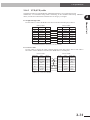
2-14-3 UTP (STP) cable
The Ethernet cables are standardized by ANSI/TIA/EIA568A. To avoid miswiring and malfunction, we recommend using cables conforming to this standard. When using 10BASE-T
cables, it must have transmission characteristics of category 3 or higher.
Between T-568A
Ethernet Unit
■ Straight-through cable
Use this cable to connect the HUB to the robot controller and other party's device.
Between T-568A
Signal name
Color
Pin No
Pin No
Color
Signal name
TD+
Green/White
1
1
Green/White
TD+
TD-
Green
2
2
Green
TD-
RD+
Orange/White
3
3
Orange/White
RD+
Not use
Blue
4
4
Blue
not use
Not use
Blue/White
5
5
Blue/White
not use
RD-
Orange
6
6
Orange
RD-
Not use
Brown/White
7
7
Brown/White
Not use
Not use
Brown
8
8
Brown
Not use
* Pins 4, 5, 7, 8 are not used for 10BASE-T.
* Straight-through cable also connects between T-568B and T-568B.
■ Crossover cable
Use this cable to connect the robot controller directly with other party's device. This cable is
also used to connect HUBs in cascade (when HUBs have a cascade port).
Between T-568A
Between T-568B
Signal name
Color
Pin No
Pin No
Color
Signal name
TD+
Green/White
1
1
Orange/White
TD+
TD-
Green
2
2
Orange
TD-
RD+
Orange/White
3
3
Green/White
RD+
Not use
Blue
4
4
Blue
not use
Not use
Blue/White
5
5
Blue/White
not use
RD-
Orange
6
6
Green
RD-
Not use
Brown/White
7
7
Brown/White
Not use
Not use
Brown
8
8
Brown
Not use
2
* Pins 4, 5, 7, 8 are not used for 10BASE-T.
2-31
2-15 Supplement
2-15 Supplement
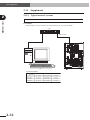
2-15-1 Typical network systems
2
Ethernet Unit
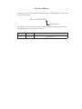
How a particular user builds up a network system depends on factors such as the scale of the network.
■ Example 1
In this example, several controllers are operated from one PC using one HUB.
HUB
1
2
3
4
5
6
7
8
10BASE-T cable
10BASE-T cable
MOTOR
OP.1
OP.3
OP.2
OP.4
PWR
SRV
XM
YRC
PB
ERR
ROB
I/O
XY
YM
BATT
XY
SE L
COM
ROB
I/O
ZR
ZM
STD.DIO
BATT
ZR
SAFET Y
RGEN
P
N
ACIN
L
RM
N
L1
EX T.E-S TOP
13 14
YRC robot controller
PC
System setup example
2-32
IP address
Subnet mask
Gateway
PC
192.168.0.2
255.255.255.0
192.168.0.1
Controller 1
192.168.0.3
255.255.255.0
192.168.0.1
Controller 2
192.168.0.4
255.255.255.0
192.168.0.1
Controller 3
192.168.0.5
255.255.255.0
192.168.0.1
N1
2-15 Supplement
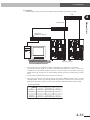
■ Example 2
In this example, many controllers are operated with the HUBs connected in cascade.
HUB
1
2
3
4
5
6
7
2
8
Straight-through cable
1
2
3
4
5
6
7
Ethernet Unit
Crossover cable
8
HUB
Cascade port
(UPLINK port, MDI port)
X
1
2
3
4
5
6
7
8
OP.1
MOTOR
HUB with cascade port
OP.3
PWR
SRV
XM
YRC
MOTOR
SRV
XM
ROB
I/O
XY
OP.3
OP.2
OP.4
YRC
PB
ERR
ROB
I/O
XY
YM
BATT
XY
YM
SE L
BATT
XY
SE L
COM
COM
ROB
I/O
ROB
I/O
•••
ZR
ZR
OP.2
ZM
OP.1
PWR
PB
ERR
BATT
ZR
OP.4
STD.DIO
RGEN
ZM
P
BATT
ZR
N
SAFET Y
STD.DIO
SAFET Y
RGEN
P
N
ACIN
L
RM
N
ACIN
L
RM
N
L1
N1
EX T.E-S TOP
13 14
L1
EX T.E-S TOP
13 14
N1
YRC robot controller
PC
* The cascade port, also sometimes called an UPLINK port or MDI port is used when connecting multiple HUBs in cascade. Straight-through cables are used to connect the
cascade ports of the HUBs together. However, crossover cables are used when connecting
HUBs not having cascade ports or when making cascade connections without using cascade
ports.
* A maximum of 4 HUB units can be connected in cascade.
* The same type network can also be built up by stacking HUBs together using so-called
stackable HUBs. In this case, Multiple HUBs connected in a stack are seen as just one large
HUB by the network so there is no limit on the number of HUB units that can be stacked.
System setup example
IP address
Subnet mask
Gateway
PC
192.168.0.2
255.255.255.0
192.168.0.1
Controller 1
192.168.0.3
255.255.255.0
192.168.0.1
Controller 2
192.168.0.4
255.255.255.0
192.168.0.1
:
:
:
:
Controller 9
192.168.0.11
255.255.255.0
192.168.0.1
Controller 10
192.168.0.12
255.255.255.0
192.168.0.1
2-33
2-15 Supplement
■ Example 3
In this example, the control PC and the controllers are separated from each other.
2
Terminator
Terminator
Ethernet Unit
10BASE-5 cable
Transceiver (MAU)
Transceiver (MAU)
Transceiver cable (AUI cable)
Transceiver cable (AUI cable)
HUB with 10BASE-5 connector
1
2
3
4
5
6
7
8
HUB with 10BASE-5 connector
1
2
3
4
5
6
7
8
MOTOR
OP.1
OP.3
OP.2
OP.4
PWR
SRV
XM
YRC
PB
ERR
ROB
I/O
XY
YM
BATT
XY
SE L
COM
ROB
I/O
ZR
ZM
STD.DIO
BATT
ZR
SAFET Y
RGEN
P
N
ACIN
L
RM
N
L1
EX T.E-S TOP
13 14
PC
N1
YRC robot controller
* The 10BASE-5 cable has a maximum length of 500 meters. However, this distance can be
extended to a maximum of 2.5 kilometers by connecting cables together and using repeaters,
etc.
System setup example
2-34
IP address
Subnet mask
Gateway
PC
192.168.0.2
255.255.255.0
192.168.0.1
Controller 1
192.168.0.3
255.255.255.0
192.168.0.1
Controller 2
192.168.0.4
255.255.255.0
192.168.0.1
Controller 3
192.168.0.5
255.255.255.0
192.168.0.1
2-15 Supplement
■ Example 4
In this example, a controller in a remote location is centrally managed over the Internet.
2
Factory 2
Factory 1
Router
Head office
Router
HUB
1
2
3
4
5
MOTOR
6
OP.1
OP.3
OP.2
OP.4
7
PWR
SRV
XM
8
YRC
PB
ERR
ROB
I/O
XY
1
2
3
4
5
6
7
8
YM
BATT
XY
HUB
SE L
COM
ROB
I/O
ZR
ZM
BATT
ZR
STD.DIO
SAFET Y
RGEN
P
N
ACIN
L
RM
N
L1
EX T.E-S TOP
13 14
N1
YRC robot controller
PC
Use of a firewall (defense mechanism to keep out intruders) is recommended to maintain security.
System setup example
IP address
Subnet mask
Head office router
133.215.0.1
255.255.255.0
PC
133.215.0.2
255.255.255.0
Factory 1 router
133.215.1.1
255.255.255.0
Controller 1
133.215.1.2
255.255.255.0
Factory 2 router
133.215.2.1
255.255.255.0
Controller 1
133.215.2.2
255.255.255.0
Gateway
133.215.0.1
133.215.1.1
133.215.2.1
* Routers must be set to match system conditions.
* To make a connection over the Internet, a global address must be set in the IP
address.
* Use of identical addresses is not allowed so customers must not use the
addresses set in the above example.
Always use the customer’s own unique address. NIC (in Japan, JPNIC) handles
the assigning and management of addresses.
2-35
Ethernet Unit
Internet
2-15 Supplement
2-15-2 Description of terminology
■ TCP/IP (Transmission Control Protocol/Internet Protocol)
TCP/IP is a general term for a group of standard protocols for carrying out communications
over the Internet centering around TCP and IP protocols. Computers and PCs capable of accessing the Internet all use TCP/IP protocols.
The Ethernet unit for YRC series contains TCP, IP, ICMP, ARP and TELNET protocols among
TCP/IP protocols.
Ethernet Unit
2
* The protocols making up
IP
TCP
ARP
UDP
TELNET
ICMP
HTTP
FTP
TCP/IP protocols
TCP/IP are also comprised
of many protocols other than
those shown in the figure on
the left. Protocols are a set
of conventions (or rules) that
must be mutually complied
with so that controllers and
PCs can communicate with
the other party.
■ Ethernet
The Ethernet is basically one type of standard for network system hardware. Ethernet is a
network invented by the Xerox Corporation (USA) in the early 1970's and currently forms an
international standard known as IEE802.3. The Ethernet physically consists of cable types such
as 10BASE-2, 10BASE-5, and 10BASE-T that differ from each other in terms of transmission
cable types such as maximum cable length and the maximum number of connections. The Ethernet unit for YRC series uses cables conforming to 10BASE-T specifications.
Besides TCP/IP, the protocols most commonly used on the Internet are NetBEUI and IPX/SPX,
etc.
Another feature of the Ethernet is the use of CSMA/CD as a data transmission method.
(see below).
■ CSMA/CD (Carrier Sense Multiple Access with Collision Detection)
CSMA/CD is a method of sending signals, developed by combining a CSMA data transmission
method with a transmission error handling method called CD.
CSMA refers to joint use of one transmission cable by many devices connected over a network.
CSMA is therefore a method for checking network status beforehand and then transmitting the
data after verifying that transmission is possible.
CD is a method for handling data collisions that occur on the network. In this method, when a
data collision (conflict) occurs, that data is re-transmitted after a randomly selected time period
has elapsed.
Many devices can be connected to the Ethernet by using these CSMA/CD methods. However,
performance cannot be guaranteed in real-time because of transmission standby (time awaiting
transmission) and retransmissions.
2-36
2-15 Supplement
The IP address is actually comprised of 2 address sections. One section is the network address.
The network address is the address of the network itself. The other section is the host address
section. The host address is an address for identifying each device on that network. The IP address, as shown below, uses the first through the Nth bits as the network address, and the N+1
bit through 32nd bit as the host address. (The value of N is determined by the subnet mask.)
1
N N+1
32
IP address Network address section Host address section
In an IP address of 192.168.0.2, for example, if the N value (network length) is 24 bits, then the
network address section is 192.168.0, and the host address section is 2. Generally, in a network
address, the host address section is 0 and the network length is listed behind the address. In the
above example, this would be shown as 192.168.0.0/24.
One network can be connected with as many devices as there are addresses to identify them.
However, host address bits having all zeroes (0), or all ones (1) are reserved and so cannot be
used. In the above example, though the host address can identify 256 devices, the numbers 0
and 255 cannot be used so the maximum number of devices that can actually be connected is
254.
192.168.0.0/24
192.168.1.0/24
192.168.0.1
192.168.1.1
Maximum of
Maximum of
192.168.0.100 254 devices
192.168.0.254
192.168.1.100 254 devices
connected by
router
Network A
192.168.1.254
Network B
Any company (organization) can freely select a host address but when attempting to connect
their network to the Internet, that company (organization) cannot select the network address
on their own. An application to acquire a network address must be made to the NIC (in Japan,
JPNIC). If connecting one's network to the Internet is not necessary, then any company can
freely select a network address, as well as a host address.
If there is no need to connect to the Internet, then use of the following addresses is allowed.
10.0.0.0 through 10.255.255.255
172.16.0.0 through 172.31.255.255
192.168.0.0 through 192.168.255.255
(1 unit of class A)
(16 units of class B)
(256 units of class C)
An address acquired by making application to NIC on the other hand is referred to as a global address.
2-37
2
Ethernet Unit
■ IP address
The IP address is a unique number assigned to each device to identify that device on the network and prevent the same number from being used by different devices. (More accurately,
an IP address is assigned to each network interface, since once PC may sometimes be installed
with multiple network interfaces.) In a TCP/IP protocol, the data transmit source and destination
are specified by this IP address. The IP address consists of 32 bits (4 bytes) so can be expressed
with this number without changes, however it is normally expressed as a decimal number separated by periods (.) at each byte (in other words, four sets of numbers separated by periods). An IP address of 0xC0A80002, for example, is normally expressed as 192.168.0.2
2-15 Supplement
■ Subnet mask
The subnet mask is used to separate the IP address into a network address section and a host address section. The network address bit is set to 1, and the host address bit is set to 0.
The subnet mask, just like the IP address is expressed as a decimal number of 32 bits (4 bytes)
with each byte separated by a period (or four sets of numbers separated by periods). So if the
subnet mask is 255.255.255.0, then the network address section is 24 bits.
Ethernet Unit
2
A company (organization) is generally assigned only one network address when applying to the
NIC for an IP address. The company making the application falls within one of classes A, B or
C depending on the scale of the company. Class B for example, has a network length of 16 bits
and can be assigned a network allowing connection of up to 65533 devices. However, unless
changes are made, this network cannot efficiently perform the required managing and processing tasks. So such a network is normally set with subnet masks to divide it into an appropriate number of smaller networks. When a class B network for example, is set with a
subnet mask of 255.255.255.0, a total of 256 settings can be made allowing up to 254 devices
to be connected.
■ MAC address (Media access control address)
The MAC address, also called the Ethernet address is a hardware type identification number
(6 bytes) set in each network interface. The MAC address is set in each device during the
manufacturing stage and therefore does not have to be set by the user.
Each device in the Ethernet system is identified by means of this MAC address. In other words,
the IP address is automatically converted to a MAC address, even when communicating by
means of a TCP/IP protocol.
Basically the user does not normally have to even be aware of the MAC address. However, if
there are communication problems, then the interrelation of the IP address and MAC address
can be checked to find out if the cause of the problem is overlapping (identical) IP addresses.
■ HUB
A HUB is a device used for connecting devices such as PCs by way of a 10BASE-T network.
The HUB has multiple ports that allow connecting modular jacks and twisted pair cables fitted
with these modular jacks connect to the HUB from each device.
The HUB may have different type connectors depending on whether the HUB is for 10BASE-2
or 10BASE-5. Various types of networks can be constructed by means of these HUBs.
■ Router
The router is a device for mutually connecting networks together. The router is controlled based
on a sophisticated process. The router sends data with an external destination from an internal
network to an external network, and sends data received from an external network, to an internal network. Designated data is discarded in a filtering process to help maintain network
safety.
The router IP address is set as the gateway address in each network device. This setting allows
data to be correctly sent and received by each device on the network.
2-38
Revision History
A manual revision code appears as a suffix to the catalog number on the front
cover of the manual.
Cat. No. I151E-EN-01
Revision code
The following table outlines the changes made to the manual during each revision.
Page numbers refer to the previous revision.
Revision code
Date
Revised content
01
July 2010
Original production