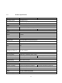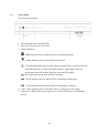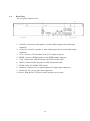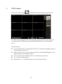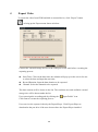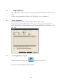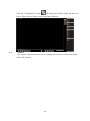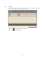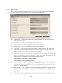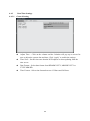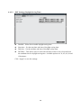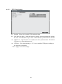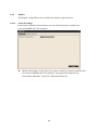
1
Real-time NETWORK VIDEO RECORDER User’s Manual 12000 Ford Road, Suite 110, Dallas, Texas 75234 Tel: 972-247-1203 Fax: 972-247-1291 www.idview.com 1 Regulatory Information FCC compliance: This equipment has been tested and found to comply with the limits for a digital device, pursuant to part 15 of the FCC Rules. These limits are designed to provide reasonable protection against harmful interference when the equipment is operated in a commercial environment. This equipment generates, uses, and can radiate radio frequency energy and, if not installed and used in accordance with the instruction manual, may cause harmful interference to radio communications. Operation of this equipment in a residential area is likely to cause harmful interference in which case the user will be required to correct the interference at his own expense. FCC Conditions This device complies with part 15 of the FCC Rules. Operation is subject to the following two conditions: 1. This device may not cause harmful interference. 2. This device must accept any interference received, including interference that may cause undesired operation. Attention! This is a class A product which may cause radio interference in domestic environment; in this case, the user may be urged to take adequate measures. Safety Precautions ˙To reduce risk of fire or electric shock, do not expose this appliance to rain or moisture. ˙Do not place the appliance near to heaters, other heat sources or under direct solar irradiation. ˙Make sure the ventilation slot on the appliance is not covered during operating. ˙To prevent risk of electric shock, connect only to a proper earth grounded outlet. Do not operate appliance with other none specified power supplies. ˙Do not attempt to modify or use the supplied AC power cord if it is not the exact type and rating required. ˙Do not attempt to disassemble the appliance. Contact qualified service personnel for maintenance. ˙Handle the appliance with care. Do not strike or shake, which may damage the appliance. Notice ˙Information in this document is subject to change without notice. 2 Table of Contents 1 Introduction 7 1.1 Features 7 1.2 Product Specification 8 1.3 Front Panel 10 1.4 Rear Panel 11 1.5 Remote Control (Optional) 12 1.6 Packing Detail and Installation Error! Bookmark not defined. 2 General Operation 13 2.1 Login 13 2.2 Add IP Cameras to NVR 15 2.2.1 Full Auto Install Mode 15 2.3 Live Viewing 22 2.3.1 Basic Operation 22 2.4 Search and Playback Operation 25 2.4.1 Basic operation 25 2.3.2 Calendar 26 2.3.3 Search operation 26 2.3.4 Playback operation 28 3 PTZ Control 29 4 Export Video 30 5 Export Player 31 5.1 Player Installation 31 5.2 Starting the Player Program 31 3 6 System Setup Menu 33 6.1 Camera 34 6.1.1 Settings 35 6.1.2 Record Settings 42 6.1.3 Schedule Settings 43 6.2 Network 44 6.2.1 Network Settings 44 6.2.2 Network Service 47 6.2.3 Network Notification 49 6.3 Alarm Settings 51 6.3.1 Alarm Input Settings 51 6.3.2 Exception Management 52 6.4 System Settings 53 6.4.1 Device Setting 53 6.4.2 User Settings 54 6.4.3 Date/Time Settings 55 6.4.4 Display 58 6.4.5 Disk 60 6.4.6 Miscellaneous 62 6.4.7 Configuration 64 6.5 Information 65 6.5.1 General Information 65 6.5.2 Log 66 7 Web Viewer Operation 67 7.1 Connecting to NVR 67 7.2 Login 67 4 7.3 Remote Live View 69 7.4 Remote Search and Playback 71 7.4.1 Search by Time 71 7.4.2 Search by Channel 72 7.4.3 Search by Event 73 7.4.4 Web Viewer Playback Operation 74 7.4.5 Web Viewer Setup Menu 75 7.4.6 Remote Export 76 7.4.7 Remote PTZ Control 78 8 VS Viewer for iOS and Android 81 8.1 Android System 81 8.2 iOS System 85 9 CMS Pro Operation 90 9.1 Begin Installation 90 9.2 Start CMS Pro from the PC 96 9.3 CMS Pro UI Overview 97 9.4 Login 98 9.5 Connect the program with device 99 9.5.1 Add Device Manually 99 9.5.2 Remove or Edit device setting 100 9.5.3 CMS Pro Group Video 101 9.6 Live Video 103 9.7 Playback Video 105 9.7.1 Search for Playback Videos 107 9.7.2 Search operation 107 5 9.8 CMS Export 112 9.9 CMS PTZ Configuration 114 9.10 CMS System 115 6 1 Introduction The compact size standalone 4/8CH Network Video Recorder can operate independently with local live monitoring, recording, playback and local configuration. It supports up to H.264 High Profile decoding. The high-efficiency 4/8CH NVR can perform up to 4/8CH Full HD recording with multiple recording modes, including continuous, manual, scheduled, alarm and motion recording. 1.1 Features Local operations and configurations: With local operations and configuration technology, the complicated network configurations are able to perform locally. High Resolution local display: It supports live and playback directly from HDMI or VGA monitors or TV. It supports HDMI interface which is able to connect to HDMI monitor or TV in full HD (1920x 1080) resolution. Plug-and-Play installation: It provides users with automatic installation to reduce the redundancy in operation and maintenance costs. Linux-embedded, highly reliable standalone NVR. Megapixel recording (up to 10Mbps per channel): It supports megapixel recording (up to 10Mbps per channel) from different IP cameras. Record up to 4/8 channel Full HD video input. Video search by date and time, event and channel: It supports convenient video search by date and time, event and channel on the local playback interface. Digital watermark: It provides the digital watermark utility to verify whether the videos are original or not. Digital zoom for live and playback Remote monitoring of NVRs by Android phones, iPhone and iPad. CMS: It provides with free bundle CMS to manage 128 channel cameras. Live monitoring with maximum 32 channels simultaneously and one device playback. Support 3 internal SATA HDDs, up to 9TB. Convenient Control of PT cameras: It supports PT (Pan/Tilt) cameras to adjust directly from the NVR and they can be viewed on the local display. 7 1.2 Product Specification System 4 Channel 8 Channel Operating System Embedded Linux Operations Live, Recording,Playback,Backup & Remote access Control Mode USB mouse, IR remote control, Webpage, CMS Video Decompression H.264 HP/MP/BP, up to 1080p30 IP Camera Inputs 4 channel; each one is up to 1080p30 8 channel; each one is up to 1080p30 Audio Input 1 x RCA Output 1 x RCA 2-way Audio Support Display Display mode Full screen/Multi-screen/PIP/Sequence Output 1x HDMI(1920x1080p60),1xVGA(up to 1920x1080, 60Hz) Sequence Support OSD GUI Remote View Via IE Web Viewer, CMS Mobile Viewing on Smartphone/Tablet PC Yes; iOS, Android Recording Recording Mode Continuous, scheduled, alarm, motion Recording Capability Up to 120 fps at Full HD(1920x1080) Pre Recording 5 seconds Post Recording 300 or above seconds Up to 240 fps at Full HD(1920x1080) Playback & Backup Display mode Full screen/Multi-screen Playback capability 4 channel simultaneous playback Playback control Play/Pause/Step/Fast forward/Rewind/Fast rewind Search Control By Date/Time, Events Export Through USB/Webpage/CMS Internal Storage up to 3 x SATA Ports 8 8 channel simultaneous playback Network Support TCP/IP,SMTP,DHCP,DDNS,PPPoE,UDP,SSL,RTP,RTSP,NTP Ethernet 1x10/100Mbps(WAN), 1x10/100/1000Mbps(LAN) I/O USB 2; 1 for mouse control and 1 for backup Alarm 8 Alarm in/ 2 Alarm out RS485 1; Support Pelco D, Pelco P Security Watermark Yes User Privilege 3 Levels of User Access Support Environmental Power 12V DC Dimension 355(W) x 63(H) x 265(D) mm Temperature 0°C ~ 40°C ** The specifications are subject to change without any notice.** 9 1.3 Front Panel The front panel includes: 1. Power button: Power On/Off NVR. 2. IR receiver: Receiver for IR remote. 3. Status indicators: : HDD Indicator turns on when system is accessing hard disk : Alarm indicator turns on when alarm is detected. : Exception indicator turns on when system exception alert is detected, such as disk full, disk error, no disk, network disconnect, illegal login, disk over temperature, fan fail, network fail, power loss and IP conflict. : Rec indicator turns on when NVR is recording. : WAN indicator turns on when NVR is connecting to WAN port. : LAN indicator turns on when NVR is connecting to LAN port. 4. CH1~CH8 : Indicators turn on when the video is connected to the system. 5. USB port : USB port for connecting devices, such as USB mouse or USB flash device. 10 1.4 Rear Panel The rear panel connectors are: 1. Audio In: Connect the microphone or camera audio output to the audio input connector. 2. Audio Out: Connect a speaker or other audio output device to the audio output connector. 3. VGA: Connect a VGA monitor to the VGA output connector. 4. HDMI: Connect a HDMI monitor to the HDMI output connector. 5. LAN: Connect hub with IP cameras via RJ-45 network cable. 6. WAN: Connect NVR to Internet via a RJ-45 network cable. 7. RS485 socket: For RS485 PTZ control. 8. Alarm In: Connect to 4 or 8 alarm inputs to the alarm input connectors. 9. Alarm Out: N.C or N.O type alarm signal out. 10. Power: Plug the DC12V power source into the power socket. 11 1.5 Remote Control (Optional) The NVR can be operated through the remote controller. The remote control operation is showing in below figure. Batteries (2xAAA) must be installed before operating. 1. ID Button: Press ID button + number key to switch to the NVR that user would like to control. Press a number between 1 and 9 corresponding to the unit ID user wish to control. The user ID must be set in the device before operating. 2. Export Button: Enable/disable Export menu. 3. F1/F2 Button: Reserved. 4. ACK Button: Alarm acknowledged. 5. Alphanumeric Buttons 6. Display Button: Press to switch the display mode. 7. Sequence Button: Press to enable/disable sequence display mode. 8. Zoom Button: For digital zoom in/out operation under digital zoom mode. Or for zoom in/out control under PTZ mode. 9. Focus Button: For focus control under PTZ mode. 10. PTZ Button: To enable/disable PTZ control menu. 11. Direction/Enter Button: The Direction buttons are used to navigate the focus display windows or select items in the menu. The Enter button is used to confirm the selection. 12. Search Button: To enable/disable playback mode. 13. Menu Button: To enable/disable configuration menu. 14. Playback Control Buttons: Same as playback operation on playback mode. 15. PTZ control Buttons: Same as PTZ control operation on PTZ mode. 12 2 2.1 General Operation Login It is requested to login after boot up if the user authentication is enabled. Click on the User and Password column to bring up the virtual keyboard to enter the preset user account and password to login to the system. The default user name/password is: Administrator: admin/admin Operator: operator/operator Guest: guest/guest If Auto logout is enabled, the system will automatically logout after the preset time. To login to the system, left click on the mouse to bring up the login menu. 13 The functions available can be limited by setting passwords. Access to the unit’s functions is determined by the user level of the user logged in. Authority Instructions based on 3 levels of users Administrator Operator Guest View live Yes Yes Yes OSD Yes Yes Yes Live Multiple-up Yes Yes Yes Zoom Yes Yes Yes Pan/Tilt/Zoom (PTZ) Yes Yes No Playback Yes Yes No Export Yes Yes No Acknowledge Alarm Yes Yes No Configuration Yes No No 14 2.2 2.2.1 Add IP Cameras to NVR Full Auto Install Mode When the first time connect IP cameras to the NVR, the NVR will pop up install wizard window. NVR provides plug and play feature if user install NVR in “Full Auto Install” mode. User just need to click “Full Auto Install” and then the NVR will automatically configure IP address of a camera connected by LAN. The NVR will then detect the IP camera and display image soon. The connection of the LAN port is for IP cameras. The connection of the WAN port is for the NVR to Internet. This mode is suitable when the LAN is connected to a hub. Please click “Full Auto Install” and the NVR will automatically configure IP cameras connected by LAN. After few seconds, the NVR will detect the IP cameras and display image. The connected IP cameras must be specific IP camera models. The IP camera is powered on before the NVR is power on. Note: User also can go to ConfigurationSystem DeviceInstall WizardGo to bring up Install Wizard. When the NVR does not configure the IP camera automatically, it might be the below reasons. It is not specific IP camera model. The IP camera is not powered on before the NVR is power on. 15 2.2.2 Manual Install Mode If user would like to add IP camera manually, please follow the below steps. Step 1. Click “Manual Install” and press “Next’ to the next page. Step 2. User can configure NVR device settings. User can change the device name, select the desired display language, enable or disable authentication or keep the recorded data in hard disk or not. After finish the device setting, please click “Next” to the next page. 16 Step 3. User can configure network settings for WAN and LAN. The connection of the LAN port is for IP cameras. The connection of the WAN port is for the NVR to Internet. The NVR provides the options for user to access to the NVR through DHCP, Fixed IP or PPPoE. Select the option user would like to use to enable and configure the settings. When the LAN port of the NVR is connected to IP cameras via a hub, user can choose DHCP or Fixed IP to enable and configure the settings. After finish the network settings, please press “Next” to the next page. 17 Step 4. User can configure Date/Time settings of the NVR. After finish the Date/Time settings, please press “Apply” to save user’s changes and proceed to the next step. Adjust Time : Click on the column and the Calendar will pop up on screen for user to adjust the system date and time. Click Apply to enable the settings. Time Zone: Set the time zone that the NVR adjusts to when updating from the time server. Date Format: Select date format from DD/MM/YYYY, MM/DD/YYYY or YYYY/MM/DD. Time Format: Select time format between 12 Hours and 24 Hours. NTP On/Off: To enable or disable NTP synchronization. 18 Step 5. After press “Apply” button, the NVR will start to scan the LAN environment to search for the specific IP cameras. 19 Step 6. After NVR gets the specific IP cameras, it will display the IP camera list. User can click “Add” button to add IP camera into desired channel. Step 7. After adding IP cameras into NVR, NVR will start to configure the parameters of the IP cameras. 20 Step 8. When NVR finish the configuration of the IP cameras, it will pop up the success message and IP camera also successfully add into NVR. 21 2.3 2.3.1 Live Viewing Basic Operation The NVR will enter into the Live View mode after user login to the system. Use mouse to double click on any video channel to bring it up to full screen display. The basic operation icons are showing on the main screen, the functions are: (A) System indicators, Channel selection and Audio output selection The system indicator is showing general system status for each input channel. (1) The color of the button stands for the status for each channel as listed: White – Normal, the camera input is installed and enabled. Grey – The video input is disabled. Blue – Video Lost. Yellow – Motion triggered. Red – Alarm triggered. (2) Recording status indicator Red – Recording Grey – Not Recording (3) Audio output selection 22 Click on the Audio icon on the channel user would like to display, the audio output will switch to the selected channel. (4) To switch channel in the display window, move the focus channel to the selected window, click on the channel button user wish to display, the channel will be switched. (B) Display mode control : Single view display mode PIP display mode Quad display mode 3+3 display mode Sequence display mode Show/Hide OSD Switch display to full screen display mode (C) Function Control Alarm acknowledge, click to disable buzzer when alarm is triggered Click to enable/disable Setup menu Click to bring up Export menu Click to switch to search and playback mode Under full screen mode, click the button to enable Digital Zoom function. Right click on the mouse to drag on the screen to zoom in the selected area. Click to bring up the PTZ control panel Click to Logout from the current user’s privilege. 23 (D) Current streaming information: It indicates the current video streaming resolution, frame rate and data rate. (E) Current date time: It indicates the current system time. 24 2.4 2.4.1 Search and Playback Operation Basic operation To search and playback the video, click “Playback” button on the main page to switch to playback mode as show below. The display mode controls are the same as under Live View mode. The function controls are as below: Click to bring up the Export menu Under full screen mode, click to enable Digital Zoom function. Right click on the mouse to drag on the screen to zoom in the selected area. Click to switch to live view mode 25 2.3.2 Calendar The calendar on the screen shows the recorded data contains in the hard drives. The date highlighted in orange means there’s recorded data of the date in the hard drives. The red highlighted date indicates the current search date. Click on the calendar to select the date user would like to search. 2.3.3 Search operation The recorded file list is showing in the column below, the files can be searched by “Time”, “Channel” and “Event”. Select the search type and the results will show in the list below. Double click on the selected file then the video will start to play on the display window. 2.3.3.1 Search by Time Select Time Search, all the video files of the selected date will be shown in the list. Each file contains maximum 60 minutes of the video. Select the time range user would like to view and double click the item to start to play on the display window. 26 2.3.3.2 Search by Channel Select the channel that user would like search. All the event video files of the selected date and channel will be shown in the list. Select the event video user would like to view and double click the item to start to play on the display window. 2.3.3.3 Search by Event The system provides the option to search the video by each event type and channel. All the event video files of the selected event type and channel will be shown in the list. Select the event video user would like to view and double click the item to start to play on the display window. 27 2.3.4 Playback operation Please refer to the below for the playback control function: 2012-05-28 02:28:58pm The progress bar shows the current playback status and timeline. Drag the time indicator on the progress bar to move to the selected timeline to playback. On the time bar, it also indicates the initial and end time of the current playback section. Click to playback video Click to pause video Click to reverse playback Click to switch to fast forward playback, use and to adjust playback Speed, in x0.25, x0.5, x1, x2, x4 and x8. Pause the video and click the button to step forward playback. Click to fast forward to the next section Click to switch to fast reverse playback, use and to adjust playback speed, in x1, x2, and x4 and x8. Pause the video and click the button to step reverse playback. Click to fast backward to the previous section 28 3 PTZ Control Click on the “PTZ” button to enable the PTZ control panel as shown below. The PTZ control will apply the PTZ command to the current focus camera channel if it’s connected to a PTZ device which include RS485 PTZ device or Network PTZ device. The functions are: 8 way pan/tilt control: To pan/tilt the PTZ device to up/down/left/right/up right /up left /down right / down left. Speed : There are five levels of speed (Lowest/Low/Normal/High/Highest) can be applied when press the pan/tilt control. Set: To save the current PTZ position as it’s internal preset position. Go : Go to the preset position Quick Preset 1–10 : The quick button to go to the preset positions. 29 4 Export Video To export the video from NVR hard disk to external device, click “Export” button to bring up the Export menu shown as below. Connect the external storage device to the USB port on the unit before executing the exporting process. Start Time: Click on the date/time, the calendar will pop up on the screen for user to select the date and input the start time. Record Duration: Input the data duration to be exported. Channel: Select the channels to be exported. The data contents will be shown in the list. The total data size and available external storage size will be shown under the list. User can assign the recording path by clicking the “ Click Start to execute the exporting process. Open Folder” icon. User can view the exported video by the Export Player. Click Export Player to download to the pen drive if the user does not have the Export Player installed. 30 5 Export Player The Export Player allows user to view video exported from the NVR or Web viewer on a PC. (System operating platform: Windows XP, Windows Vista, or Windows 7.) 5.1 Player Installation The Export Player can be downloaded from NVR or Web Viewer. On the NVR, insert the USB pen drive then start the Export page as shown below. Click “Export Player” button and the system will automatically store the Player in the pen drive. 5.2 Starting the Player Program Double click on the “Player.exe” file to start the program. The Player will be displayed as shown below: 31 To open a video export file, click “Open” button to select the exported file. Drag the files to the window that would like to display. The Player will automatically start to play the video. Note: The Player can only play multiple channels that are within the same time duration. The main functions are: Single view display mode Quad display mode Under full screen mode, click to enable Digital Zoom function. Right click on the mouse to drag on the screen to zoom in the selected area. Click to take a snapshot of the selected video. Click to verify the video is authentic or not. The progress bar shows the current playback status and timeline. Drag the time indicator on the progress bar to move to the selected timeline to playback. 32 Click to playback video Click to pause video Click to switch to fast forward playback, use and playback speed, in x0.25, x0.5, x1, x2, x4 and x8. to adjust Click to stop playback video Click to enable or disable audio playback. Drag the slide bar to adjust the volume. When audio is on, the user can move the focus window to the select the channel that would like to play. Click to convert the video file of the selected channel to AVI format. 6 System Setup Menu 33 Click the “Configuration” button , the setup menu will be enable and shown as below. Please refer to below for the setup menu functions 6.1 Camera The camera setup menu allows user to configure the behaviors related to the input video of IP cameras. 34 6.1.1 Settings In the Camera-Settings menu, it displays the current IP camera information, including camera title, IP address and IP camera connecting status. Click on the for detailed setup of each IP camera. Click on the to delete IP camera. 35 6.1.1.1 Basic Setting In the Camera-Settings-Basic menu, user will see the IP camera basic information and user can configure stream profiles of the IP cameras from the NVR. Camera title – Click on the column, the virtual keyboard will pop-up for user to input the camera title. IP Address – It indicates the IP address of the IP camera. MAC address – It indicates the MAC address of the IP camera. Manage Port – User can configure the port of the IP camera. User Name – User need to input the user name of the IP camera. The NVR will display the default IP camera user name. Once user make the change of the user name of the IP camera, please input the new user name. Password – User need to input the password of the IP camera. The NVR will display the default IP camera password. Once user make the change of the password of the IP camera, please input the new password. The default IP camera user name: admin The default IP camera password: 1234 Stream Profiles – There are different stream profiles of the IP camera. User can select the desired stream profile as the recorded main profile and sub profile. Click “Apply” to save the changes. Main Profile – The resolution of the main profile reflects the stream profiles selection. User can configure “Frame rate” and “Max Bitrate” of the IP camera from NVR. Sub Profile – The resolution of the sub profile reflects the stream profiles selection. 36 User can configure “Frame rate” and “Max Bitrate” of the IP camera from NVR. Note: Once user make the changes of stream profiles, frame rate and max bitrate and click “Apply” to save the new parameters, IP camera will start to proceed the configuration. During the process, it will result in the video loss of IP camera and user will see the blue screen on the configured channel. 37 6.1.1.2 Advanced Setting In the Camera-Settings-Advanced menu, user can configure video color settings of IP cameras from the NVR. User can adjust video brightness, contrast, saturation, sharpness, mirror and flip of the IP cameras. Press “Exit” to back the previous page. 38 6.1.1.3 Video Loss Handle Settings In the Camera-Settings-Video Loss Handle Settings menu, it allows user to define the system behaviors while there’s video loss triggered. Buzzer – Select On to trigger buzzer when video loss is detected. Trigger Alarm Out – The corresponding alarm output setting. Send Email – Select On to send e-mail to the preset mail account when video loss is detected. Send Alarm Notification – Select On to send alarm notification when video loss detected. (Reserved) Triggered Camera – The system allows user to trigger multiple cameras for event recording, select the cameras that would like to be triggered when video loss is detected. Click ”Apply” to save the settings. 39 6.1.1.4 Motion Handle Settings In the Camera-Settings-Motion Handle Settings menu, it allows user to define the system behavior while there’s motion triggered. Enabled – Select On to enable motion handle. Buzzer – Select On to trigger buzzer when motion is detected. Spot on Main Monitor – Select On to spot on main monitor when motion is detected. Trigger Alarm Out – The corresponding alarm output setting. Send Email – Select On to send e-mail to the preset mail account when motion is detected. Send Alarm Notification – Select On to send alarm notification when motion detected. (Reserved) Triggered Camera – The system allows user to trigger multiple cameras for event recording, select the cameras that would like to be triggered when motion is detected. Click ”Apply” to save the settings. 40 6.1.1.5 PTZ settings In the Camera-Settings-PTZ menu, it allows user to configure the settings if the NVR is connected to a RS485 PTZ camera or Network PTZ camera. Enabled – Select On to enable PTZ control. PTZ Type – It will display RS485 PTZ or Network PTZ. It depends on which PTZ type NVR connects. PTZ Protocol – Select the correct PTZ protocol type. Baud Rate – Select the speed used to transmit instruction or information through the RS485 port on the NVR. Data Bit - The data bit used for transferring. This can be set to 8 or 7 through RS485 connection. Parity: This selects the transmission level of the connection through RS485 connection. Choose either None, Odd, or Even . Stop Bit - This field is to set the stop bit for the RS485 connection. This can be set to 1 or 2. Address - The address must set to the same address of that RS485 PTZ camera. Click ”Apply” to save the settings. 41 6.1.2 Record Settings In the Camera-Record menu, user can define the recording behavior in the record setup menu. Each channel can be configured independently. Click on the selected channel to bring up the setup page. Record Audio – Enable or Disable the audio recording. Pre-event – Set the pre-event recoding duration. The maximum pre-recording duration is 5 seconds. Post-event – Set the post-event recording duration. Copy – To copy the setting to the other channels. Click ”Apply” to save the settings. 42 6.1.3 Schedule Settings In the Camera-Schedule menu, user can define the recording schedule and recording behavior for each individual channel in the below page. column To setup schedule, select the channel from the left column, the recording option for the channel will be shown in the right column. Click on the day(Sun ~ Sat) user would like to set schedule, check in the to enable the timelines and select the recording behaviors. User can configure multiple timelines for each day. Click “Day Copy” to select the day user would like to copy to. Click “CH Copy” to allow user to copy the settings of the whole week from one channel to other channels. Click “Apply” to save the changes. 43 6.2 6.2.1 Network Network Settings The Network function must be enabled and configured properly in order to access and configure the IP cameras and NVR. 6.2.1.1 WAN In the Network-Settings-WAN menu, user is required to set up the WAN setting properly in order to access NVR via internet. The NVR provides the options for user to access to the NVR through DHCP or Fixed IP or PPPoE. Select the option user would like to use to enable and configure the settings. Click “Apply” to save the settings. 44 6.2.1.2 LAN In the Network-Settings-LAN menu, user is required to set up the LAN setting properly in order to access IP cameras via intranet. The NVR provides the options for DHCP or Fixed IP in LAN environment. Select the option user would like to use to enable and configure the settings. Click “Apply” to save the settings. 45 6.2.1.2 DDNS In the Network-Settings-DDNS menu, user can select DDNS to configure the Dynamic DNS. The setup page is shown as below. Select On to enable DDNS. Input DDNS provider and enter the required information. Click “Apply” to save the settings. 46 6.2.2 Network Service 6.2.2.1 Service In the Network-Service-Service menu, user can enable/disable NTP Server and enable/disable UPnP. User can enable NTP Server to make NVR as NTP Server. After enable NTP Server, IP camera can synchronize the date and time with NVR. User can enable or disable UPnP on NVR. After enabled, the NVR connects to a network and NVR automatically establishes working configurations with other devices. Click “Apply” to save the settings. 47 6.2.2.2 DHCP Server In the Network-Service-DHCP Server menu, user can select on to make NVR as DHCP Server. After enable DHCP Server, NVR is able to assign IP address to IP camera in the LAN environment. The range is from 0 ~ 255. Click “Apply” to save the settings. 48 6.2.3 6.2.3.1 Network Notification Alarm Notification In the Network-Notification- Alarm Notification, the network alarm can be transmitted to up to 3 addresses. Server IP 1~3 – Input the addresses for system to send the notification. Server port – Select the transmission port for network alarm messages. Click “Apply” to save the settings. 49 6.2.3.2 E-Mail Notification In the Network-Notification-E-mail Notification menu, user is able to set the Email addresses and input related information. If “Send Email” is enabled in video loss, motion, alarm settings or system exception and when they are being triggered, the e-mail will be sent according to the E-mail notification setting. To Email address 1-3 – Allows user to input up to 3 email address for alarm message to send to. From Email address – Input the Email address of the sender (NVR) Email Subject – Input email subject. SMTP Server – Assign the SMTP (e-mail) server’s name. SMTP Port – Assign the port number used by the SMTP server. SSL – To enable SSL if mail server needs to be encrypted by SSL. Authentication – To enable if the SMTP server requires authentication. (user name / password). User name / Password – Input the login user name and password if the SMTP Server requires authentication. Send test mail – Click to send the test email according to the current settings. Click “Apply” to save the settings. 50 6.3 6.3.1 Alarm Settings Alarm Input Settings In the Alarm-Settings menu, user can define the alarm behaviors and the corresponding actions for triggered alarm. Alarm input – Select the alarm input number from 1 to 8, the corresponding settings will show in the window. Enabled – Select On to enable the alarm. Alarm name – Input the name for the alarm. Alarm type – Select the alarm trigger type. N.O. – Normal open contact, N.C – Normal Close contact Trigger Duration – Select the trigger type and time duration Timeout – The alarm will last for the set time duration. Transparent – The alarm output remains active until the triggered event ends. Non-Stop – The alarm will be continuously active until user presses “ACK” key. Alarm Handle – To configure the system monitor and alert behavior when the alarm is triggered. The settings include buzzer, spot option, trigger alarm out, send Email, send alarm notification. Triggered Camera – The system allows user to trigger multiple cameras for event recording, select the cameras that would like to be triggered when alarm is detected. Click “Apply” to save the settings. 51 6.3.2 Exception Management In the Alarm-Exception menu, it allows user to define the system behavior when there’s an exceptional event occurred. The exceptional events are including Disk full, Disk error, No disk, Network Disconnect, Illegal Login, Disk Over Temperature, Fan Fail, Power loss and IP conflict. Select the exception and define the behaviors as below: Buzzer – Select On to enable buzzer when the exceptional events occur. Trigger Alarm Out – Select the Alarm out to trigger when the exceptional events occur. Send Email – Select On to send Email when the exceptional events occur. Send Alarm Notification – Select On to send alarm notification when the exceptional events occur. (Reserved) 52 6.4 6.4.1 System Settings Device Setting In the System-Device menu, user can configure the device related settings. Device Name – Input the name for the NVR. Device No. – Input the number for the NVR. Language – Select from the list for the language to be displayed on the local NVR. IR Remote Controller – Set the IR remote control ID for remote control use. Each IR remote controller can control up to 9 NVRs. For example, if user set NVR IR remote controller as ID#1, user can press “ID” and “1” on the IR remote controller to control ID#1 NVR. Enable Authentication – Select On to active the user login. If user select Off, no user name or password is required to access the system. Auto Scan & Add IP-Cameras –Select On to active auto scan & add IP cameras. The NVR will continually scan the IP camera and check whether there is a new IP camera in the LAN environment. When the NVR detect a new IP camera in the LAN environment, NVR will automatically add the IP camera into NVR when there is still spare channel existing in the NVR. Install Wizard – Click “Go” to bring up Install Wizard menu. Click “Apply” to save the settings. 53 6.4.2 User Settings User setting page is where user can add or delete users on the system. The default user name and password are as below. Administrator: admin/admin Operator: operator/operator Guest: guest/guest Double click the selected user or click on Click on to delete the user. However, at least one administrator is required to operate the system. Click on to edit the user settings. to add new user. 54 6.4.3 6.4.3.1 Date/Time Settings General Setting Adjust Time – Click on the column and the Calendar will pop up on screen for user to adjust the system date and time. Click “Apply” to enable the settings. Time Zone – Set the time zone that the NVR adjusts to when updating from the time server. Date Format – Select date format from DD/MM/YYYY, MM/DD/YYYY or YYYY/MM/DD. Time Format – Select time format between 12 Hours and 24 Hours. 55 6.4.3.2 DST Settings (Daylight Saving Time) Enabled – Select On to enable daylight saving time. Start time – Set the start date and time of daylight saving time. End time – Set the end date and time of daylight saving time. DST Bias – This allows users to select the amount of time to move forward from the standard time for daylight saving time. Available options are 30, 45, 60, 90 and 120 minutes Click “Apply” to save the settings. 56 6.4.3.3 NTP Client Settings Enabled – Select On to enable NTP synchronization. Sync. Interval (mins) – Input the frequency that the system automatically updates the time. Click the button “Sync. Now” if immediately synchronization is needed. NTP Server – Input the time server address for time synchronization. The default NTP server is “time.stdtime.gov.tw”. NTP Port – The default setting is “123”, user can define NTP port according to the network environment. Click “Apply” to save the settings. 57 6.4.4 Display The Display setting allows user to define the monitor output behavior. 6.4.4.1 General Settings In the System-Display-General menu, user can select the proper resolution for connected HDMI and VGA monitors. Monitor Resolution –Select Auto for system to identify resolution automatically for connected HDMI and VGA monitors. The supported resolutions are: 1920x1080, 1440x900, 1366x768, 1280x1024,1024x768. 58 6.4.4.2 Main Monitor Settings In the System-Display-Main Monitor menu, user can configure the main monitor display mode and the contents. Sequence enabled – Select On to enable sequence display on main monitor. Dwell – Input the dwell time in seconds for sequence display. Camera – Select the cameras to be appeared on the sequence display. 59 6.4.5 Disk In the System-Disk menu, user can review and manage the hard disk settings of the NVR. 6.4.5.1 General Settings In the System-Disk-General, user can enable or disable overwrite. The user is also able to select the auto delete days. Overwrite – Select On to enable hard disk overwrite when it’s full. Auto delete – The hard disk will automatically erase the data after the selected number of days. Select “0” to disable the function. Click “Apply” to save the settings. 60 6.4.5.2 Disk Management In the System-Disk-Disk menu, it is to manage and display the information of all the available hard disk. The information is including the hard disk total storage size, current temperature, usage status, available data start/end time. Click “Format” to format the selected hard disk. WARNING: Format the hard disk will erase all existing data! 61 6.4.6 6.4.6.1 Miscellaneous Shutdown In the System-Misc-Shutdown menu, user can select to reboot or shutdown the system from this page. 62 6.4.6.2 Firmware Upgrade In the System-Misc-Firmware upgrade menu, user is able to upgrade NVR firmware by store the firmware in USB drive. To upgrade the firmware, connect a USB flash device which contains the firmware version user would like to update. Click “Upgrade” to start the firmware upgrading. The system reboot is required to complete the firmware upgrade. WARNING: Do not disconnect USB device or turn off the NVR power during the upgrading otherwise it might cause NVR defective. Note: To upgrade 4CH NVR to 8CH NVR by license key, please contact the service people. 63 6.4.7 Configuration Restore Factory Default– User can load factory default by clicking “Restore” button. Select the items that would like to be excluded from back to the factory default, the selected items will remain as the current values User Configuration – Select the configuration name and click “Save” to save the current configuration settings. Or user can select the configuration from the list and click “Restore” to restore the selected settings. Import Configuration – Click “Load from USB” button to upload NVR configuration settings from a USB flash device. Export Configuration – Click “Save to USB” to save the current NVR configuration settings to a USB flash device. 64 6.5 6.5.1 Information General Information In the Information-Information menu, it displays the general system information. The information includes model name, firmware version, serial number, WAN IP address, WAN MAC Address, LAN IP address and LAN MAC address. 65 6.5.2 Log In the Information-Log menu, it allows user to filter and review the system event log. Click the date column and the calendar will pop up for user to select the day to be displayed. Click the items user would like to review and to show in the event log. The filtered log will be displayed in the page. Click “Save to USB” with a USB flash device connected to the unit, the filtered log will be saved to the USB device. 66 7 Web Viewer Operation 7.1 Connecting to NVR Users can remote access the NVR through Microsoft Internet Explorer to view live/recorded video and manage the NVR. Before accessing the web viewer, make sure that the PC and NVR are both connected to the internet and the network feature is enabled. For NVR network setup, please refer to Configuration Network Settings. 7.2 Login Open IE browser and input NVR IP address in the address bar. When accessing this feature for the first time, user will be prompted by the browser to install Active X. The browser will pop up the below dialog for installation, click “Yes” to accept and start the installation. 67 After installing the Active X, the login page will be displayed for users to enter the User name and Password. Users can also select the OSD language, date format and time format from the login page. Click “Login” to enter the web viewer. The user name/password are the same as the NVR login, the defaults are: Administrator: Operator: Guest: admin/admin operator/operator guest/guest 68 7.3 Remote Live View After login to the system, the web viewer will automatically display a 4-screen live video. Double click on a video display window and it will display full screen in the selected channel. The system indicators on the screen show the system status, channel status and for user to control the audio display channel. Please refer 2.2.1 Basic Settings. The basic operation icons are showing on the main screen, the functions are: Click for Live view mode Click to switch to search and playback mode Click to switch to Setup menu 69 Click to switch to Export mode Click to enable the PTZ control panel Click to Logout from the current user’s privilege. Full screen display mode Quad display mode 3+3 display mode Show/Hide OSD Two-way audio Click to take a snapshot of the selected video. In full screen, click to zoom in/out of the selected video in 2x, 4x and 8x. 70 7.4 Remote Search and Playback Click the “Playback” button to switch to playback mode. The video can be searched by Time, Channel and Event, select the search type to start searching. 7.4.1 Search by Time The calendar on the screen shows the recorded data contains in the NVR hard drives. The date highlighted in orange means there’s recorded data of the date in the hard drives. The red highlighted date indicates the current search date. The recorded section list of the current selected day will be shown on the screen. Double click on the selected recorded file to start the playback. 71 7.4.2 Search by Channel Search by Channel allows user to search the event video by channel. Select the date from the calendar, and select the channel user would like to view. The event video list of the selected channel will be shown on the screen. Double click on the selected recorded file to start the playback. 72 7.4.3 Search by Event Search by event allows user to search the event video list by channel and by event type. Select the channel user would like to view (user can also click All On or All off to enable or disable all channels), then select the event type (Alarm, Motion and Video Loss), the event video list of the selected channel and event type will be shown on the screen. Double click on the selected recorded file to start the playback. 73 7.4.4 Web Viewer Playback Operation Click on the “Playback” button to switch to the below menu. The basic Playback operations are as below. The progress bar shows the current playback status and timeline. Drag the time indicator on the progress bar to move to the selected timeline to playback. On the time bar, it also indicates the initial and end time of the current playback section. Click to playback video Click to pause video Click to switch to fast forward playback (2x), user can also control the playback speed by clicking and , in x0.25, x0.5, x1, x2, x4 and x8. Click to fast forward to the next section Click to fast backward to the previous section 74 7.4.5 Web Viewer Setup Menu Click on the “Config” button to switch to the setup menu page as below. User can configure all the NVR settings remotely through the web viewer. The setup menu operation is the same as in the NVR. Please refer to the Chapter 6 System Setup Menu for the setup details. 75 7.4.6 Remote Export Click on the “Export” button to bring up the remote export menu, this allows user to export the video file from the NVR. To export the video, select the date from the calendar, the starting time of the video and channels that user would like to export. (Click All On or All off to enable or disable all channels.) Input the duration time user would like to export, the maximum search duration is 60min. Click Search to start, the searched video files will be listed on screen. The maximum video file size is 2000MB, the system will automatically create new file if the searched result is over 2000MB. Double click on the selected item and the system will pop up message as below, select the location user would like to store then click Save to execute the downloading. 76 User can view the exported file on the Export Player. If the user does not have the Player installed in the PC, click Export Player button to download the player to the PC. Please refer to Chapter 5 for Export Player operation. 77 7.4.7 Remote PTZ Control Click the “PTZ” button to enable the PTZ control panel. This allows user to control the connected PTZ camera. The basic operation is the same as the NVR PTZ control. Please refer to Chapter 3 for detail operation. 78 7.4.8 Remote Snapshot Click the “Snapshot” button in live mode or playback mode to store the current image as a still image and save in the PC folder. 79 7.4.9 Remote Digital Zoom The function allows user to enlarge the live video at 2x, 4x and 8x in live mode or in playback mode. Move the focus to the selected video. Click “Full Screen” first and then click “Digital Zoom” button icon and the selected area which user would like to enlarge. 80 8 8.1 VS Viewer for iOS and Android Android System System requirement To be able to install and run VS viewer, please make sure user’s Android device is running Google Android 2.2 or later, and the device is with wireless network supported. Download the APP Step1. Launch “Google Play Store” Step2. Search for “VS Viewer”, tap Install, the system will pop-up the menu for user to Accept & download the APP. The download should then begin. The VS Viewer icon will show on the device after the download is completed. 81 Step3. Tap “VS Viewer” icon to launch the APP. Step4. Tap “Add” to add new NVR. Step5. Input NVR name, Host (IP Address), Port, User name and Password. Tap on “Save” to activate the settings. 82 To operate the APP Tap on the NVR that user would like to open the view window. Rotate the screen, the orientation of the screen rotates with the tablet as user turn it. 83 To select the view channel Tap on to switch the display mode between full screen and quad screen display. Select the display mode, and indicate the channel by tap on the number that user would like display in the selected display window. Tap on again to hide the selections. PTZ Control (Reserved) 84 Others To enable/disable audio display Under full screen mode, tap on the icon to enable the digital zoom function. To operate, place two fingers at once on the display window and pinch them together to zoom out, or spreading them apart to zoom in. The zoom in/out display ratio will be shown on the screen. (from 0.2X to 25X) Tap on Snapshot icon to store the current image as a still image and save in the device folder. 8.2 iOS System System requirement To be able to install and run VS viewer, please make sure user’s iOS device is running iOS 5.1 or later version, and the device is with wireless network supported. Step1. Select “App Store” Step2. Search for “VS Viewer”, tap on “Install APP”, the system will pop-up the request for user to enter login password to start downloading. The downloading should then begin. The VS Viewer icon will show on the device after the download is completed. 85 Step3. Run “VS Viewer” Step4. Tap on Step5. to add new NVR. Input NVR name, Host (IP Address), Port, User name and Password. Tap on “Save” to activate the settings. 86 To operate the APP Tap on the NVR that user would like to open the view window. 87 Rotate the screen, the orientation of the screen rotates with the tablet as user turn it. To select the view channel Tap on to switch the display mode between full screen and quad screen 88 display. Select the display mode, and indicate the channel by tap on the number that user would like display in the selected display window. Tap on again to hide the selections. PTZ Control (Reserved) Others To enable/disable audio display Under full screen mode, tap on the icon to enable the digital zoom function. To operate, place two fingers at once on the display window and pinch them together to zoom out, or spreading them apart to zoom in. The zoom in/out display ratio will be shown on the screen. (from 0.2X to 25X) Tap on Snapshot icon to store the current image as a still image and save in the device folder. 89 9 CMS Pro Operation 9.1 Begin Installation Simply double click user’s CD-ROM drive icon “Setup.exe” to launch the installer. Once the CMS Pro installer starts, it should begin to check the compatibility with the operating system user are running this installation on. If user are installing the software in Windows XP, Vista, Windows 7, please make sure the software is installed with administrator privilege. System Requirement The following are minimum system requirements for CMS. Operating System Microsoft Windows XP, Windows Vista, Windows 7 CPU Minimum Intel i5 or higher RAM Minimum 4GB of RAM Independent Graphic Card Minimum 512MB The CMS Pro installer is in multi-language. User can choose the installer language. 90 If user’s software is without .NET Framework 4.0, the CMS Pro installer will require user to install .NET Framework 4.0 to ensure CMS operation. After click yes, there will pop up the installation progress bar to indicate the progress. The .NET Framework 4.0 installer will ask user to review the license terms. After user accept the license terms, please click “ Install” to proceed further. 91 Please click “Next” to proceed further. 92 Once .NET Framework 4.0 software install successfully, it will pop up the below complete message. Then user can begin to install CMS Pro software. 93 Once the .NET Framework 4.0 install successfully, user can begin the installation by clicking “Next’. The CMS Pro installer will ask user to review the license terms. After user accept the license terms, please click “ I Agree” to proceed further. 94 The CMS Pro installer will install the program in a default directory. User can either accept the default or choose the directory user would like to save the installer. And click “install” to proceed with the installation. The CMS Pro installer will show the installation process. 95 Once the installation is complete, click “Finish” to exit the CMS Pro installer. 9.2 Start CMS Pro from the PC The program automatically creates a shortcut icon on user’s PC after CMS Pro install successfully. Simply double click the icon to launch the program. If user are running the CMS Pro software in Windows XP, Vista and Windows 7, please make sure the software is installed with administrator privilege. 96 9.3 CMS Pro UI Overview (A) Menu Bar: This is where user can access all functions of the software. (B) Device List: This is where user can add or delete or edit device group. (C) PTZ Control Panel: This is where user can pan, tilt, zoom the selected PTZ cameras. (D) System Information: It provides the information of CMS version. User can change the date format, time format and login authentication per user’s requirements. (E) Playback: Once user press the playback, it will launch playback control UI to have the further operations. (F) Play or Stop: This is to play or stop the video streaming. (G) Video: This is where the video are displayed. 97 9.4 Login After installing the below digital signature, the login page will be displayed for users to enter the User name and Password. Click “OK” to enter CMS Pro Software. The default user name/password for CMS Pro is: Administrator: admin/admin The program provides multi-language support. To change the display language, please select the desired language from the CMS language drop-down menu. 98 9.5 Connect the program with device The main purpose of the CMS Pro software is to manage multiple devices. User would need to tell the program which device user need to manage. User do that by adding one or more devices through the device list. 9.5.1 Add Device Manually Click the mouse right button on the “Device List” icon and “Add Device” will pop up in the same page to add it manually. It is required for the information shown below before successfully adding the device to the program. Please input device IP address, HTTP Port, User Name and Password. CMS Pro only supports RTSP Port at 554. Please note user need to use the CMS Pro administrator’s user name and password of the selected device. Without administrator privilege, user is unable to add the selected device. The default user name/password for CMS Pro is: Administrator: admin/admin 99 9.5.2 Remove or Edit device setting Once user have one or more devices added to the program, the “Edit Device Name”, “Device Setting” and “Delete Device” will become available. Simply click on the mouse right button on the selected device from the list and choose the corresponding buttons to edit device name, edit device setting or delete the device. Edit Device Name – User can edit the device name by simply click on the mouse right button on the selected device to “Edit Device Name”. After input the new device name, click”Edit” and the new device name will be updated to the device list. Device Setting – Once the IP address, user name or password of the selected device has been changed, user can input the new information by clicking on the mouse right button on the selected device. Delete Device – User can remove the device from the device list by clicking on the mouse right button on the selected device. 100 9.5.3 CMS Pro Group Video User can create the group to contain different videos from different devices. Click the mouse right button on the “Group” and it will pop up “Add Group”. Press “Add Group” and the default “Group 1” will be generated. The group number is increased by numerical order. Click the mouse right button on “Group 1” and the below drop-down menu will be displayed. 9.5.3.1 Edit Group Content Before edit group content, user need to stop stream first. Then user can drag and drop either devices or channels from the device list to the desired video windows. 101 9.5.3.2 Open Group Stream After finish the edit group content, click “Open Group Stream” on the desired group to play the video streaming. 9.5.3.3 Edit Group Name User can modify the group name. 9.5.3.4 Delete Group User can remove the group from the group list by clicking on the mouse right button on the selected group. 102 9.6 Live Video This page basically provides user the ability to view, and manage the video streams of each channel. The menu bar is available for each video window. The menu bar provides the following functions: The basic operations are showing on the main screen, the functions are: Full screen display mode Quad display mode 9-up screen display mode 16-up screen display mode 25-up screen display mode 36-up screen display mode Click to Logout from the current page Click to turn on/off live audio 103 Show/Hide OSD Two-way audio Click to take a snapshot of selected live video Click to digital zoom the selected live video Click to stop or play the live video Take a snapshot: The function allows user to take the snapshots of the live video and save them on user’s local computer. Move the focus to the selected video and click “Snapshot” icon. User can save the file to a desired directory. Digital Zoom: The function allows user to enlarge the live video at 2x, 4x and 8x. Move the focus to the selected video. Click “Full Screen” icon. Then click “Digital Zoom” icon and the selected area which user would like to enlarge. 104 If user click the “Minimize” icon in the live mode, user will see the display on the tool bar of user’s computer. 9.7 icon Playback Video The program supports 1 device synchronous playback in full screen or multi-screen view. To start looking for playback videos, click “Playback” button first. The menu bar is available for each video window. The menu bar provides the following functions: The basic operations are showing on the main screen, the functions are: 105 Full screen display mode Quad display mode 9-up screen display mode 16-up screen display mode 25-up screen display mode 36-up screen display mode Click to turn on/off recorded audio Show/Hide OSD Two-way audio Click to take a snapshot of selected recorded video Click to digital zoom the selected recorded video Click to stop or play the recorded video If user click the “Minimize” icon in the playback mode, user will see the display on the tool bar of user’s computer. 106 icon 9.7.1 Search for Playback Videos Simply select a device from the drop-down device list and double click the selected device. It will pop up the calendar. 9.7.1.1 Calendar The calendar on the screen shows the recorded data contains in the hard drives. The date highlighted in red means there’s recorded data of the date in the hard drives. The gray highlighted date indicates the current search date. Click on the calendar to select the date user would like to search. 9.7.2 Search operation The recorded file can be searched by “Time”, “Channel” and “Event”. Select the search type first, choose a date, and click “Search” button. The results will show in the list. Double click on the selected file then the video will start to play on the display window. 107 9.7.2.1 Search by Time The recorded section list of the current selected day will be shown on the screen. Double click on the selected recorded file to start the playback. 9.7.2.2 Search by Channel Search by Channel allows user to search the event video by channel. Select the date from the calendar, and select the channel user would like to view. The event video list of the selected channel will be shown on the screen. Double click on the selected recorded file to start the playback. 108 109 9.7.2.3 Search by Event Search by event allows user to search the event video list by channel and by event type. Select the channel user would like to view (user can also click All On or All off to enable or disable all channels), then select the event type (Alarm, Motion and Video Loss), the event video list of the selected channel and event type will be shown on the screen. Double click on the selected recorded file to start the playback. 110 9.8 CMS Playback Operation The basic playback operations are as below. The progress bar shows the current playback status and timeline. Drag the time indicator on the progress bar to move to the selected timeline to playback. On the time bar, it also indicates the initial and end time of the current playback section. Click to playback video Click to pause video Click to switch to fast forward playback (2x), user can also control the playback speed by clicking and , in x0.25, x0.5, x1, x2, x4 and x8. Click to fast forward to the next section Click to fast backward to the previous section 111 9.8 CMS Export Click on the “Export” button to bring up the export menu, this allows user to export the video file from the device To export the video, select the date from the calendar, the starting time of the video and channels that user would like to export. (Click All On or All off to enable or disable all channels.) Input the duration time user would like to export, the maximum search duration is 60min. Click Search to start, the searched video files will be listed on screen. The maximum video file size is 2000MB, the system will automatically create new file if the searched result is over 2000MB. Double click on the selected item and the system will pop up message as below, select the location user would like to store then click Save to execute the downloading. 112 User can view the exported file on the Export Player. If the user does not have the Player installed in the PC, click Export Player button to download the player to the PC. Please refer to Chapter 5 for Export Player operation. 113 9.9 CMS PTZ Configuration User can synchronize PTZ settings from all cameras connected to the NVR on the network or user can create and add new PTZ preset points to those cameras through CMS Pro. The basic operation is the same as the NVR PTZ control. Please refer to Chapter 3 for detail operation. 114 9.10 CMS System Click on the “System” button to bring up the system menu, this allows user to change the Date Format, Time Format, Login Authentication and CMS Version. Date Format: Select date format from DD/MM/YYYY, MM/DD/YYYY or YYYY/MM/DD. Time Format: Select time format between 12 Hours and 24 Hours. Login Authentication: User can change CMS Pro password. Please input the old password and input the desired new password and reconfirm it. After confirmation, click “Edit”, the new password has been updated. The new password will be required when next time user login again. CMS Version: It indicates CMS Pro current version. 115