1
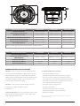
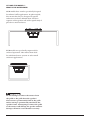
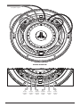
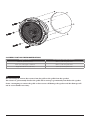
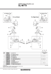
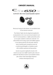
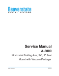
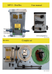
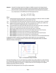
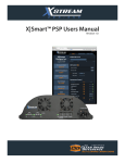
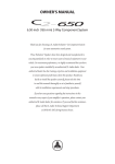
M650-CCX / M770-TCX / M770-CCX
marine coaxial speaker systems
owner’s manual
Thank you for purchasing a JL Audio Marine Coaxial Speaker System.
With proper installation, your new speakers will deliver
years of listening pleasure.
For maximum performance and extended warranty
coverage, we highly recommend that you have your new speakers
installed by an authorized JL Audio dealer. Your authorized
dealer has the training, expertise and installation equipment to ensure
optimum performance from this product. Should you
decide to install the speakers yourself, please take the time
to read this manual thoroughly so as to familiarize yourself
with its installation requirements and setup procedures.
If you have any questions regarding the instructions in this
manual or any aspect of the operation of your speakers, please contact
your authorized JL Audio dealer for assistance. If you need further
assistance, please call the JL Audio Technical Support Department
at (954) 443-1100 during business hours.
D
F
A
B
C
E
Physical Specifications
M650-CCX
M770-TCX
M770-CCX
Nominal Diameter
6.5 in. / 165 mm
7.70 in. / 196 mm
7.70 in. / 196 mm
Frame Outer Diameter (A)
6.55 in. / 166 mm
7.70 in. / 196 mm
7.70 in. / 196 mm
Bolt Hole Circle (B)
5.79 in. / 147 mm
6.92 in. / 176 mm
6.92 in. / 176 mm
Motor Overmold Outer Diameter (C)
3.75 in. / 95 mm
4.42 in. / 112 mm
4.42 in. / 112 mm
Frontal Grille Protrusion* (D)
0.91 in. / 23 mm
0.99 in. / 25 mm
0.99 in. / 25 mm
Mounting Hole Diameter (E)
5.00 - 5.25 in. / 127-133 mm
6.25 in. / 159 mm
6.25 in. / 159 mm
Mounting Depth (F)
2.95 in. / 75 mm
3.15 in. / 80 mm
3.15 in. / 80 mm
M770-TCX
M770-CCX
Notes: *Frontal grille protrusion measured from mounting surface
Physical Specifications
M650-CCX
Mounting Application
Continuous Power Handling
(RMS Method)
Frequency Response
Cockpit (Infinite Baffle)
55 Hz - 25 KHz (± 3 dB)
Efficiency @ 1W/1m
89.5 dB
91.0 dB
91.0 dB
Nominal Impedance
4 ohms
4 ohms
4 ohms
70 Watts / channel
Tower (Small Enlosure) Cockpit (Infinite Baffle)
100 Watts / channel
100 Watts / channel
45 Hz - 25 KHz (± 3 dB) 45 Hz - 25 KHz (± 3 dB)
MARINE SPEAKER Specifications
Woofers: Injection-molded, mica-filled polypropylene
Included Components and Parts:
cone bodies with UV inhibitors, 1.00-inch (25 mm) voice
• Two Coaxial Speaker Systems
coils, low-profile/ progressive-roll spiders and synthetic
• Two Polymer Woofer Grilles (attached to speaker)
rubber surrounds. DMA-optimized, long excursion design
• Two 1-inch (25 mm) Tweeters (mounted to grilles)
for enhanced output and bass response. Centrex® UV-
• Two 2-Way Crossover Networks (mounted to woofers)
resistant polymer baskets and grilles
• Twelve #8 x 1 3/8-inch (35 mm) philips-head stainless-
Tweeters: 1-inch (25 mm) treated silk dome tweeter,
• Twelve #8 stainless-steel washers
steel screws for speaker mounting
neodymium magnet, ferrofluid cooled
and damped.
for speaker mounting
• Two red jumper wires (pre-terminated)
• Two black jumper wires (pre-terminated)
Crossover Networks: True 2-way networks with 1st order
• Mounting Template
low-pass and 2nd order high-pass circuits. Polyswitch
solid-state tweeter protection
Due to ongoing product development, all specifications are subject to
change without notice.
2 | JL Audio - M650-CCX / M770-TCX / M770-CCX Owner’s Manual
CCX and TCX MODELS...
What is the difference?
CCX models have woofers specifically designed
for infinite-baffle applications. In plain english,
this means that they are designed to operate
without an enclosure behind them. The bass
response of the speaker will suffer significantly if
placed in a small enclosure.
TCX models are specifically engineered for
enclosed operation. This makes them ideal
for wakeboard tower systems or other small
enclosure applications.
Do not attempt to remove the tweeter from
the grille or the grille from the speaker!
The tweeter is permanently fixed to the grille
and its wiring is permanently attached to the
speaker frame. Attempting to remove the grille
or the tweeter will damage the speaker and this
damage will not be covered under warranty.
3
BEFORE YOU BEGIN INSTALLING
•Turn off the audio system. It is also advisable
to disconnect your battery system whenever
performing installation work.
•Before cutting, drilling or inserting any screw,
check clearances on both sides of the planned
mounting surface. Also check for any potential
obstacles, such as wiring harnesses, fuel lines,
hydraulic lines, etc. Check both sides of the
vessel before cutting any holes.
Tweeter Protection
The crossover networks are equipped with
an advanced electronic tweeter protection circuit
designed to minimize the possibility of tweeter
failure. This electronic device monitors current
going to the tweeter and will disconnect the
tweeter from the signal when it senses overload.
Should this occur while listening to the audio
system, simply reduce the volume for a few
seconds and the protection circuit will reset
itself automatically.
•Wear protective eyewear at all times and a dust
mask and gloves when drilling or cutting.
It is absolutely vital that your coaxial speaker
system is connected as shown in this manual.
Failure to connect the system as shown will
result in damage to your speakers which
is NOT covered under warranty. Do not
substitute different crossover networks!
While these speakers are designed to be water
and spray resistant, they are not designed to be
submerged or to withstand high-pressure water
spray. Please exercise care when washing your
boat to avoid damaging your speakers. Do not
install on submersibles, personal watercraft or any
other vessel likely to be under water at any time.
Prolonged exposure to sound pressure levels in
excess of 100dB can cause permanent hearing
loss. This high-performance speaker can
exceed this level. Please exercise restraint in its
operation in order to preserve your ability to
enjoy its fidelity.
When installing speakers in your vessel, it is
extremely important to secure them firmly. This
applies not only to the speakers themselves,
but also any structure they are mounted to. If
not firmly attached, the speakers can become
dangerous projectiles in a collision. Please
review the mounting information carefully and
use the supplied marine-grade hardware to
mount this product.
4 | JL Audio - M650-CCX / M770-TCX / M770-CCX Owner’s Manual
to amplifier output
Wiring diagram:
to
woofer
negative
input
to
tweeter
negative
input
from
amplifier
negative
output
from
amplifier
positive
output
to
tweeter
positive
input
to
woofer
positive
input
5
Installing the SPEAKERS
Once the mounting locations have been
established, run speaker cables from the amplifier
outputs to the mounting locations. If you are
running cables through bulkheads, drill holes for
the cable and use a urethane or plastic grommet
to protect the wire from chafing in the hole. Make
sure that the cables will clear any mechanical
devices in the boat and secure them with wire ties.
COAXIAL INSTALLATION PROCEDURE
Diagram A (page 7) shows the typical
installation procedure into a fiberglass panel,
using the supplied hardware. Always follow proper
safety procedures. Use eye-protection at all times
and a dust mask and gloves when cutting.
1) Choose a flat mounting surface that has
sufficient depth and air space behind it to
accept the speaker.
2) Using a hole saw or jigsaw, cut a mounting
hole for your respective speaker model (see
“Mounting Hole Diameter (E)” specifications,
page 2). If using a jigsaw, tracing the supplied
mounting template will provide you with an
accurate line on which to cut.
3) Run the speaker cable from the amplifier
output to the mounting location.
4) Place the speaker in the hole (or use the
mounting template) and mark the screw
hole locations using a sharp, pointed tool.
5) Remove the speaker and drill a pilot hole (see
Pilot Hole Recommendation chart,
page 7) in each of the screw locations.
It is also advisable to use a hand-driven
countersink tool on each hole to further
inhibit gel-coat cracking of fiberglass panels.
6) Connect the speaker wires from the
amplifier and the jumper wires from the
speaker's attached crossover module to the
woofer and tweeter connections. See Wiring
Diagram on page 5.
7) Place the speaker into the opening.
8) While holding the speaker firmly in its
mounting location, place the #8 x 1 3/8-inch
Phillips pan-head mounting screws (with
washers) and snug in a criss-cross pattern,
then tighten with a hand screwdriver in a
criss-cross pattern.
If you have any questions about the installation
or setup of your coaxial speaker system not
covered in this manual, please contact your
dealer or technical support.
JL Audio Technical Support:
(954) 443-1100
9:00 AM – 5:30 PM (Eastern Time Zone)
Monday - Friday
Non-standard installations may require different
hardware. Always use marine-grade, stainless-steel
fasteners to ensure a secure, reliable installation.
6 | JL Audio - M650-CCX / M770-TCX / M770-CCX Owner’s Manual
#8 SCREW: PILOT HOLE RECOMMENDATIONS
Fiberglass Thickness
Recommended Pilot Hole Drill Size
0.125 in. (3.18 mm) or less
7/64 in. (2.78 mm) pilot hole
foam core / fiberglass sandwich
7/64 in. (2.78 mm) pilot hole
larger than 0.125 in. (3.18 mm)
1/8 in. (3.18 mm) pilot hole
Do not attempt to remove the tweeter from the grille or the grille from the speaker!
The tweeter is permanently fixed to the grille and its wiring is permanently attached to the speaker
frame. Attempting to remove the grille or the tweeter will damage the speaker and this damage will
not be covered under warranty.
7
Limited Warranty - MARINE SPEAKER SYSTEMS (USA)
JL AUDIO warrants this product to be free of defects in materials and workmanship for a period of
ninety (90) days from the original date of purchase. The warranty term is extended to one (1) year if
installation is performed or approved by an authorized JL AUDIO dealer (proof of installation or approval
required on purchase receipt).
This warranty is not transferable and applies only to the original purchaser from an authorized
JL AUDIO dealer. Should service be necessary under this warranty for any reason due to manufacturing
defect or malfunction, JL AUDIO will (at its discretion), repair or replace the defective product with new
or remanufactured product at no charge. Damage caused by the following is not covered under warranty:
accident, misuse, abuse, product modification or neglect, failure to follow installation instructions,
unauthorized repair attempts, misrepresentations by the seller. This warranty does not cover incidental
or consequential damages and does not cover the cost of removing or reinstalling the unit(s). Cosmetic
damage due to accident or normal wear and tear is not covered under warranty.
Warranty is void if the product’s serial number has been removed or defaced.
Any applicable implied warranties are limited in duration to the period of the express warranty as
provided herein beginning with the date of the original purchase at retail, and no warranties, whether
express or implied, shall apply to this product thereafter. Some states do not allow limitations on implied
warranties, therefore these exclusions may not apply to you. This warranty gives you specific legal rights,
and you may also have other rights which vary from state to state.
If you need service on your JL AUDIO product:
All warranty returns should be sent to JL AUDIO freight prepaid through an authorized
JL AUDIO dealer and must be accompanied by proof of purchase (a copy of the original sales receipt.)
Direct returns from consumers or non-authorized dealers will be refused unless specifically authorized
by JL AUDIO with a valid return authorization number. Warranty expiration on products returned
without proof of purchase will be determined from the manufacturing date code. Coverage may be
invalidated as this date is previous to purchase date. Return only defective components. If one speaker
fails in a system, return only that speaker component, not the entire system. Non-defective items received
will be returned freight-collect. Customer is responsible for shipping charges and insurance in sending the
product to JL AUDIO. Freight damage on returns is not covered under warranty.
For Service Information in the U.S.A. please call
JL Audio Customer Service: (954) 443-1100
9:00 AM – 5:30 PM (Eastern Time Zone)
JL Audio, Inc
10369 North Commerce Pkwy.
Miramar, FL 33025
International Warranties:
Products purchased outside the United States of America are covered only
by that country’s distributor and not by JL Audio, Inc.
SKU#011240 - Printed in USA
MARINE_COAX-05102007