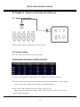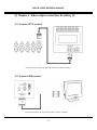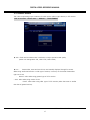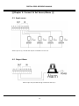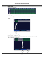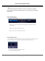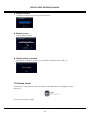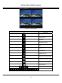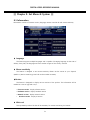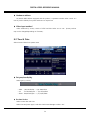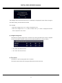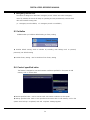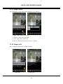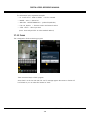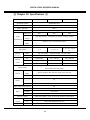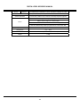
1
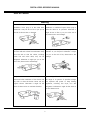
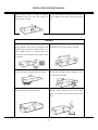
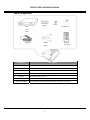
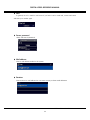
DIGITAL VIDEO RECORDER MANUAL
Preface
The user guide is about how to install and use DVR.
In addition to first-time users, the users who’ve got accustomed to the device of similar kind also
must read the user guide and carefully treat the device by complying with a caution of notice. In
particular, safety points are intended to prevent any property loss through proper use of the
device. When any problem occurs during installation or while in use, don’t hesitate to contact
seller and ask for help for maintenance. `
After reading the guide, please keep the user guide always at hand for perusal when necessary.
[Reference]
The user guide may show difference from what DVR is following change (or upgrade) in DVR
features. Please keep in mind that figures used for description may vary depending on products
on 4/9/16 channels.
DIGITAL VIDEO RECODER MANUAL
2
DIGITAL VIDEO RECORDER MANUAL
Note of Caution
Warning
Check if the power is switched off before
Check if the power is switched off before
installation. Don’t plug in at the same time.
installation or additional repair. Never plug in
Otherwise it may be set on fire or put you at
while the device is in operation. Otherwise it
the risk of electrocution or damage.
might be set on fire or put you at the risk of
fire, electrocution and damage.
Keep the cables at least 15 centimeters away
Never uplift the cover, break down, repair and
from the wall and at least five centimeters away
maintain at your disposal. Otherwise it might
from the side so that the cables, including
put you at the risk of fire, electrocution and
power line and video cable, may not be
damage.
disfigured. Otherwise it might put you at the
.
risk of fire, electrocution and damage.
Keep the device environment always clean
Input voltage of the device should come within
before and after installation of the device. Use
the range of 10 percent of specified voltage.
dry cloth to clean the device. Never use any
Use separate wall power to keep heating
organic solvent. Otherwise it might be the
appliances,
cause of electrocution or mechanic disorder.
refrigerator. Otherwise it might be the cause of
including
hair
dryer,
iron
and
fire and electrocution.
DIGITAL VIDEO RECODER MANUAL
3
DIGITAL VIDEO RECORDER MANUAL
When
strange
noise
or
smell
is
sensed,
Do not install device in humid place filled with
immediately plug out and send inquiry to
dust. It might be the cause of electrocution and
service center or seller.
fire.
Caution
Do not install the device in any place where
Do not put anything heavy on the product.
strong magnetic flow, electric wavelength and
Otherwise it may be the cause of disorder.
vibration may be sensed or where radio, TV or
other wireless device is located. Keep the
device away from magnetic flow, electric wave
or vibration.
Strong shockwave or vibration may be the
Be careful so that anything conductive may not
cause of mechanic disorder. Please be careful.
fall into the ventilation hole. Otherwise it may
be the cause of disorder.
Check if power switch and record on the front
When HDD is overloaded, you change the
side of the product is still turned on.
setting to keep recording. In that case, check
again if it would be OK to eliminate the saved
data.
DIGITAL VIDEO RECODER MANUAL
4
DIGITAL VIDEO RECORDER MANUAL
When HDD saving data gets old enough, video
When
data to be saved may suffer so much damage
immediately contact seller or service center.
any
abnormal
sign
is
detected,
that it may be irreparable. If screen appears
broken while regenerating data saved in HDD,
it
means
HDD
won’t
work
any
longer.
Immediately contact service center to replace
them.
DIGITAL VIDEO RECODER MANUAL
5
DIGITAL VIDEO RECORDER MANUAL
Check Components
screw
battery
DVR
Program CD
main
body
adapter
Battery
Remote
cable
controller
Component
Main body
Description
Stand alone Digital Video Recorder
battery
Two remote controlling 1.5V (AAA) batteries
Screw
Hard disc
Program CD
Adapter
Power cable
Remote controller
Manual and remote-controlling program
DC Power supply 12V 5A
220V power cable
Short-distance multiple remote controller (ID remote controller)
DIGITAL VIDEO RECODER MANUAL
6
DIGITAL VIDEO RECORDER MANUAL
-
Contents
-
Chapter 1. Product features and components
1-1 Features………………………………………………………………………………..…………………………………..……….9
1-2 Component names &Features on frontal part……………………………………..………..……………………10
1-3 Component names and features on rear part…………11
1-4 remote controller description…………..12
Chapter 2.
Camera connection and setting
2-1 camera connection……………………..……………………………………………………………..………………………………..13
2-2 camera setting……………..13
2-3 Camera title………..……………………..…………………………………….………………….………………..………..14
Chapter 3. Video output and setting
3-1 Connect CCTV monitor………………………………………………………………….……………….…..…………………….15
3-2 Connect VGA monitor………..……………………………………….……………………….…………..……..…….....……….15
3-3 Control screen………………………………………………….…………………………………………..……..…….....……….16
Chapter 4. Connect and set sensor/alarm
4-1 Input sensor………………………………………………………………………………………………………..…………..…….17
4-2 Output alarm…………………………………….………………………………………………………………….….……..…..…..17
4-3 Set sensor…………………………………………..……………………………………………………………….…….…….....18
4-4 Extend alarm sensor box…………………………………………………………………………………………...……...……..20
Chapter 5. Connect and set Pan-tilt
5-1 Connect pan-tilt and keyboard….……………….….……..……23
5-2 Set serial port………………………..…………….…………...……...……23
5-3 Set pan-tilt…………………………………………………………………………………………………………..………….23
Chapter 6. Connect and set hard disc
6-1 Install hard disc…………..…………………………………….…..……………………….…….………30
6-2 How to install ODD………………….…………..………………………………………...……………………….…..….………31
6-3 Control disc………….…………..…………………………………..……………………………………………….…….………32
DIGITAL VIDEO RECODER MANUAL
7
DIGITAL VIDEO RECORDER MANUAL
Chapter 7. Feature
7-1 status signal………………………………..……………………………………..….…………………….…………………….…….35
7-2 password..………………..……..…………………………………………….….………….…….……………………..…….………….37
7-3 how to set remote controller ID……40
7-4 QUAD(screen split) feature..………………..……..………………………………………...…….……………….………….…..41
7-5 SEQ(automatic channel failover)…..……..…………………………………………………
………………….…...43
7-6 emergency recording……….44
7-7 back-up feature……………….44
7-8 backup viewer feature………..48
7-9 Voice …………………………………………………………………………………….………………………………….50
Chapter 8-system setting
8-1 Information……..51
8-2 Time & date …………………………………………………………………………….…..……………………………..…...…..52
8-3 System Mgmt.……….…………………………………………………………………….…………………..……………..……….54
8-4 Set button………………….………………………………………………………………………………………………..……….55
8-5 Initialize……………….……………………………………………………………………………………………..……….56
8-6 Control specified value…………………………………………………………………………………………...56
Chapter 9. Menu setting-recording
9-1 Set recording………………………………….…………………………………………………………….…………….….………….57
9-2 Record schedule…………………………….……………………………………..………………..…………………..........………58
9-3 Set holidays……………………………….………………………………………………….………..………………............……..60
Chapter 10 Set menu – Network
10-1 IP address………………………………………………………………………….…………………………………….……………...62
10-2 Transmit network frame..…………………………………………………….………………..…………………...……65
10-3 E-MAIL………..……………………………………………………………………………………….……………………………65
10-4 warning signal type ………………………………………………67
10-5 DDNS OPTION.…………..……………………………………………………………………………………………………67
Chapter 11. Set menu-camera
11-1 Controller……………………………………………………………………………………………….………………………….73
Chapter 12 Set menu-display
12-1 OSD…………….……….………………………………………………………………...............................................….…..74
Chapter 13. Set menu-event
DIGITAL VIDEO RECODER MANUAL
8
DIGITAL VIDEO RECORDER MANUAL
13-1 event pop-up…….……….…………………………………………………………………………………….............….…..75
13-2 sense movement………………………………………………………………………………………………………………..…..76
13-3 internal buzzer………………………………………………………………….…………………………………………..…………..77
13-4 output SPOT………………………………………………………………..………………………………………………………78
Chapter 14 remote access-built-in viewer
14-1 access method….……….………………………………………………………..……….................................................….…..76
14-2 name and usage……………………………………………………..……………………….…………………………..80
Chapter 15 remote access-iPhone……………………………………………………………83
Chapter 16 remote access-window mobile phone……………………..91
Chapter 17 remote access-Android phone………………………….100
Chapter 18
Specifications…………………………………………………………………………….…………………..………………………..110
DIGITAL VIDEO RECODER MANUAL
9
DIGITAL VIDEO RECORDER MANUAL
▒ Chapter 1. Product features & components ▒
1-1. Features
The highly advanced and high-performance video recorder is designed to make it easier to install
and use with unmatched safety.
Main feature
ㆍAble to control pan-tilt by using mouse like joystick
ㆍFrontal USB terminal for easy backup
ㆍAble to back up ODD (optional)
ㆍAble to transmit GIGA network
ㆍAble to access internet with dynamic IP address
ㆍAble to transmit Dual-Stream network
ㆍAble to output simultaneously thru TV, VGA, S-VHS, Spot
ㆍAble to separately specify resolution and frame by channel
ㆍSupport a number of pan-tilt protocol
ㆍAble to activate software capable of exercising integrated control ( CMS )
Application Range
√ Banks, ATM machine, supermarket, convenience store and other places
√ residential area, apartment buildings, jewelry store, commercial building
√ places requiring safety for children such as school, elementary school and playground
√ warehouse, storage house and workplace
√ Places requiring supervision through remote control
DIGITAL VIDEO RECODER MANUAL
10
DIGITAL VIDEO RECORDER MANUAL
1-2. Component names and features on frontal part
( 4/9/16 channel, frontal part)
No.
button/feature
description
1
Direction/renew buttons
2
Menu
3
Pan-tilt
4
voice
5
backup
Retrieve backup for Video Record
6
number
Select channel and enter number
7
LED status window
Use Control button on Set Menu
Control speed and stop, pause button
Retrieve menu and move to menu on upper side , cancel
Retrieve pan-tilt menu
Retrieve Voice menu
Power, record, remote access, schedule record, emergency
record
Search
8
Feature button
Retrieve Search Menu
Split Mode
Change split mode
Sequential
Able to automatically switch screen
conversion
Reserved
Scheduled record
record
Emergency
Emergency record
record
9
USB port on frontal side
10
ODD
Mouse connection, backup and Firm ware
Able to connect to ODD depending on option
DIGITAL VIDEO RECODER MANUAL
11
DIGITAL VIDEO RECORDER MANUAL
1-3. Component names and features on rear side
(channel 4, rear side)
(channel 9, rear side)
(channel 16, rear side)
DIGITAL VIDEO RECODER MANUAL
12
DIGITAL VIDEO RECORDER MANUAL
No
Button/feature
description
1
Power connector
Adaptor power input
2
switch
power ON/OFF switch
3
VGA
4
Audio output
5
S-VIDEO
6
Audio input
7
Video output
Output connector for CCTV monitor
8
SPOT output
SPOT output connector
9
Video input
Camera video input connector
10
Serial port
Debugging port (used by manufacturer for development
Output connector for VGA monitor
Audio output connector
S-VIDEO output connector
Audio input connector
and repair)
11
Tx, Rx, Sensor, Alarm
Pan-tilt(Tx, Rx), keyboard(Tx, Rx), sensor input, alarm output
connector
12
USB port on rear side
13
LAN port
mouse, external hard disk, memory stick connector
Internet connector
1-4. Remote controller description
1
ID button
2
Split mode(Quad)
3
Backup
4
audio
5
Automatic screen switch (sequence)
6
Pan-tilt
7
search
8
Enter number or change channel
9
Retrieve menu
10
Direction key and check button
11
Emergency record
12
Scheduled record
DIGITAL VIDEO RECODER MANUAL
13
DIGITAL VIDEO RECORDER MANUAL
▒ Chapter 2. Camera connection & setting ▒
2-1. camera connection
Connect camera output to camera input on DVR’s rear side.
2-2 camera setting
This is about ways of hiding camera and screen quality.
How to set menu : retrieve menu -> camera -> set camera
▶ Covert : Once checked, live screen displays no video but record is being processed.
▶ Automatic Gain Control: Designed to automatically adjust gain depedning on camera output
signal so that pvideo may be output accroding to adjusted brightness.
▶ Gain Control: able to amplify camera input signal as much as gain.
When screen turns dark, gain increases. When it turns bright, gain decreases. In doing so,
gain is adjusted adequately.
DIGITAL VIDEO RECODER MANUAL
14
DIGITAL VIDEO RECORDER MANUAL
▶ Brightness: control screen contrast
▶ contrast : control black white
▶ color : display darkness of color
2-3 Cameral Title
This is about inputting camera title. Title appears by cahnnel.
How to set menu : retrieve menu -> camera -> camera title
Select channel to enter and enter thru virtual keyboard.
☞ Reference
Select blue capital letter “T” through virtual keyboard to change into language acceptable
to the system and then enter Hangul.
DIGITAL VIDEO RECODER MANUAL
15
DIGITAL VIDEO RECORDER MANUAL
▒ Chapter 3. Video output connection & setting ▒
3-1. Connect CCTV monitor
Connect monitor output on rear side of DVR to monitor’s Video In.
3-2. Connect VGA monitor
Connect VGA output on rear side of DVR to monitor’s VGA IN.
DIGITAL VIDEO RECODER MANUAL
16
DIGITAL VIDEO RECORDER MANUAL
3-3 Control screen
This is about optimizing output conditions for VGA monitor (video output device) or CRT monitor.
How to set menu : retrieve menu -> DISPLAY -> TV ADJUSMENT
▶ VGA : Check and set VGA monitor’s resolution to output optimal screen quality.
(Select one among 800 X 600 , 1024 X 768, 1280 X 1024 )
▶ Icon :
Camera titles, event and record icons are internally displayed through live screen.
When using small-sized monitor or older type of monitor, icons may not be visible. Please select
right one to use.
-
Normal : select when using general type of CCTV monitor
• VGA : select when using monitor for PC
• Small : select when using older type of CCTV monitor (when the screen is smaller
than that of general monitor)
DIGITAL VIDEO RECODER MANUAL
17
DIGITAL VIDEO RECORDER MANUAL
▒Chapter 4. Connect & Set Sensor/Alarm ▒
4-1. Input sensor
Sensor input is G(-) Ground and may be connected to S1 thru S4.
4-2. Output Alarm
Alarm output may be used through connection with NO, C.
DIGITAL VIDEO RECODER MANUAL
18
DIGITAL VIDEO RECORDER MANUAL
4-3 Set sensor
The system supports up to four sensor inputs.
☞ OPTION : Able to use up to 16 alarms and sensors when using separate “extended alarm
sensor box”.
How to set menu : retrieve menu -> EVENT -> SENSOR
▶ Select Use Y/N.
(Use)
(Not use)
▶ Input method : Choose between Normal Open and Normal Close.
• N/Open (NORMAL OPEN) : Generate signal when contact point closes after it was normally
left open
• N/Close (NORMAL CLOSE) : Generate signal when contact point opens after it was normally
left closed
▶ Linked channels: Able to use by linking a sensor to multiple channels.
(Not use)
(Use)
DIGITAL VIDEO RECODER MANUAL
19
DIGITAL VIDEO RECORDER MANUAL
4-4 Set alarm
Set alarm output.
The feature is designed to set off alarm during specified period when video loss occurs or when
any motion is sensed or when sensor is in operation.
☞ OPTION : Able to operate up to 16 alarms and sensors when using separate “extended
alarm sensor box”.
How to set menu : retrieve menu -> EVENT -> ALARM
The setting below is presented as an example designed to set off alarm for seven seconds when
Motion occurs. When sensor is in operation, alarm is set off for four seconds. When video loss
occurs, alarm is set off for five seconds.
( Blue-colored “sec” represents period applicable to all channels. )
HDD error seen below is designed to set off alarm when problem occurs to hard disk. The alarm
is set off during specified period. Specify period after checking. (range: a second ……)
DIGITAL VIDEO RECODER MANUAL
20
DIGITAL VIDEO RECORDER MANUAL
4-5 Extended alarm sensor box (option)
Once extended box is connected, up to 16 sensor inputs and alarm outputs may be usable.
▶ Connectivity diagram
Connect “SERIAL” port to “RS-232” port on rear side of the system.
Connect to extended BOX power and then turn power SW on.
▶ Description
① power SW
② adaptor connector
③ RS-232 port (port connected to system)
④ sensor input ( 1~16)
⑤ NORMAL OPEN alarm output : 1~16
⑥ NORMAL CLOSE alarm output : 1~16
Alarm output consists of Normal Open and Normal Close. Please check and connect.
DIGITAL VIDEO RECODER MANUAL
21
DIGITAL VIDEO RECORDER MANUAL
▶ Set menu
Able to use only after connecting to extended BOX and setting menu.
[1] Set “Use” thru Retrieve menu -> EVENT -> EXTENDED.
[2] Set RS-232 as described below thru menu -> CAMERA -> SERIAL PORT SETTING.
(transmission speed : 9600Bps, parity: none, stop bit: 1 )
DIGITAL VIDEO RECODER MANUAL
22
DIGITAL VIDEO RECORDER MANUAL
[3] Each time when sensor button is selected thru menu -> EVENT -> SENSOR, No. 1 to 16 is
changed.
[4] Each time when “alarm (number) is selected thru menu -> event -> alarm, No. 1 to 16 is
always changed.
DIGITAL VIDEO RECODER MANUAL
23
DIGITAL VIDEO RECORDER MANUAL
▒ Chapter 5. Connect and set pan-tilt ▒
5-1. Connect pan-tilt and keyboard
Connect to Tx(+) and Rx(-) before connecting to pan-tilt and keyboard.
5-2 Set serial port
Set transmission speed, parity and stop bit for RS-485 communication.
How to set menu : Retrieve menu -> CAMERA ->SERIAL PORT SETTING
Setting may vary depending on pan-tilt camera model. Refer to manufacturer’s manual.
5-3 Set pan-tilt
Additionally set model name, ID and additional conditions to activate and control installed
pantilt camera.
How to set menu : Retrieve menu -> CAMERA -> PTZ SETTING
DIGITAL VIDEO RECODER MANUAL
24
DIGITAL VIDEO RECORDER MANUAL
Set pan-tilt camera model name and ID installed in channel involved. ID should be set
as “0.” When more than one is installed, set ID differently and change ID for pan-tilt camera. Refer
to pan-tilt camera manual for change in ID.
▶ Additional pan-tilt setting
Select icons described below to additionally set pan-tilt.
• Serial Port : Select “RS-485” for control of pan-tilt camera.
DIGITAL VIDEO RECODER MANUAL
25
DIGITAL VIDEO RECORDER MANUAL
• Reverse Control : moves reversely when pan-tilt moves. The feature is usable when
camera is used in an opposite way from how it supposedly should be used. (ie: when
installing camera designed for ceiling on the ground)
• Touring Mode : supports two types. Select DVR when using saved location while
touring feature is in operation. Select “camera” when using memory of pan-tilt camera.
Select after checking specifications of pan-tilt camera.
• Speed: Specify response speed for each feature. (default: 3 )
• Change ID : Select “ See ID” to be informed of or change pan-tilt camera’s ID. Enter
“Changed ID” and then select “apply.” (If change is not permissible, you should directly
change thru pan-tilt camera.)
▶ Pan-tilt touring
Touring feature is designed to memorize point where it will be headed and then to
repeatedly make move in selected order.
• Select channel : select channel to install pan-tilt camera in.
• Preset : enter pre-set No.
• Speed : enter speed
• Dwell Time : enter stop period of pan-tilt camera.
UP to 12 pre-sets may be entered in a channel. It repeatedly moves from No.1
thru No. 12 while touring feature is in oepration.
DIGITAL VIDEO RECODER MANUAL
26
DIGITAL VIDEO RECORDER MANUAL
▶How to operate pan-tilt
Select channel and “PTZ” button to change into pan-tilt mode.
[When using frontal direction button (or remote controller)]
• Use direction button to move camera.
• Whenever pressing check, the feature changes in the order of Pan/Tilt, Zoom and
Focus. Use buttons on right and left side to move.
[When using mouse]
• When dragging the desired location outwards with mouse, camera moves at your
disposal and may move faster as it is away from the central point.
DIGITAL VIDEO RECODER MANUAL
27
DIGITAL VIDEO RECORDER MANUAL
• Whenever rolling mouse scroll button. The feature changes in the order of Pan/Tilt,
Zoom and Focus. Use the button on right and left side to move.
[Pan-tilt feature menu]
Select “PIZ” from pan-tilt mode again and feature menu appears. When pan-tilt camera
is in operation, you may use needed feature.
Able to change POP-UP location
Able to change direction of pan-tilt camera
Able to change into “extend and minimize pan-tilt”
Able to change into camera focus mode
Touring feature
Able to retrieve menu built in pan-tilt camera
Able to operate automatic focus function
Able to enter pre-set No. and save
Enter and press preset No. to move and then camera moves accordingly
Able to enter preset No.
DIGITAL VIDEO RECODER MANUAL
28
DIGITAL VIDEO RECORDER MANUAL
Adjust IRIS
Change channel
exit
DIGITAL VIDEO RECODER MANUAL
29
DIGITAL VIDEO RECORDER MANUAL
▒ Chapter 6. Connect and Set Hard Disk
▒
The model may feature up to two hard disks, one ODD and one hard disk.
The model may be used to back up saved video, which may be linked to USB or external hard
drives.
6-1 Install hard drive
When installing a single hard drive, install it in “Master HDD” as described in picture above and
connect it to power supply device and then connect SATA cable to main board “HDD1.”
When using two hard drives, install “Slave HDD” as described in picture above, connect it to
power line and connect SATA cable to main board “HDD2.”
DIGITAL VIDEO RECODER MANUAL
30
DIGITAL VIDEO RECORDER MANUAL
6-2 How to install ODD
When assembling ODD, separate front part from main body and then remove ODD cover from
front to assemble again. When separating front from main board, be careful not to touch cables
linked to main board. Fix it to ODD Bracket and then connect it to power line and then connect
SATA cable to ODD-specific port on the main board.
DIGITAL VIDEO RECODER MANUAL
31
DIGITAL VIDEO RECORDER MANUAL
6-3 Control disk
Start setting in connection with HARD DISK and ODD embedded into the system. This part is
related to recording. When setting goes wrong, error may occur to system or recording. Please
check before setting.
How to set menu : Retrieve menu -> SYSTEM -> DISK MANAGER
▶ Disk 1
Set the first hard disk connected to “HDD1” on the system.
• Set Main Disk or Mirror Disk.
(When not used, specify “None”)
• Format : format hard disk.
• volume : used volume/HD volume ( ie::
0 / 238080 MB )
DIGITAL VIDEO RECODER MANUAL
32
DIGITAL VIDEO RECORDER MANUAL
▶Disk 2
Set the second hard disk connected to “HDD2”.
• Specify Main Disk or Mirror Disk. (When not used, specify “None”)
• Format : format hard disk.
• volume : used volume /HD volume (ie :
0 / 238080 MB )
☞ Reference
• Main Disk : the first hard disk to be saved during recording.
• Mirror Disk : disk to be saved identically with main disk. When main disk causes
error, data may be retrieved due to copy version.
• When “Main Disk” or “Mirror Disk” is in operation without installing hard disk,
the system will set off beep sound. And it will be recorded as hard disk error in log.
▶ CD / DVD RW
Signal may vary depending on whether the system features ODD. When installed, the signal
may be “V.” When the opposite is true, “Ø” will be displayed.
▶ Overwrite
When the entire hard disk volume is consumed, the saved data will be erased as much as
new data entered. ( V : overwrite Ø : Not overwrite )
DIGITAL VIDEO RECODER MANUAL
33
DIGITAL VIDEO RECORDER MANUAL
▶ Auto Delete
Able to maintain data during specified period while automatically deleting data saved
previously. (range : Not use, able to set up to 120 days)
▶ Error List
When errors occur to hard disk, including read, write, connection status and recognize hard,
the date will be left. Select delete to erase the data.
▶ S.M.A.R.T(Control disk)
Able to display installed hard disk temperature. When temperature rises as specified, buzz
sound is set off.
Temperature range: Not use , 10℃ , 20℃ , 30℃ , 40℃ , 50℃ , 60℃ , 70℃ ,80℃ , 90℃
DIGITAL VIDEO RECODER MANUAL
34
DIGITAL VIDEO RECORDER MANUAL
▒ Chapter 7. Features ▒
7-1. Status signal
This provides description of icons displayed thru live screen. By providing various events, period
and record signals, it displays diverse types of icons.
Daylight savings: available when summer time is in effect
Emergency record : available when emergency record is in operation
Record schedule: available when recording is processed as scheduled
LOCK : available when screen points to Lock
Sequential conversion: available when video is in sequential conversion
Internet connected: available when internet is connected
Available when internet communication is going on
Sensor : available when sensor is sensed
Motion : available when motion is sensed in specified area
Video loss : available when no input video signal exists
Record : available when video is being saved in hard disk
The interface : available when Ghost is renewed
It is left on/off whenever “sequential conversion” is pressed for renewal
DIGITAL VIDEO RECODER MANUAL
35
DIGITAL VIDEO RECORDER MANUAL
☞ Reference
What’s The Interface?
It is a symptom only seen in D1-level record (720X480) mode. The feature is designed to
prevent GHOST phenomenon by removing unmatched odd and even numbers while renewing
video after recording. The demerit is that the renewed screen may look to have poorer quality
than the original one. Select one depending on situation. Whenever “sequential conversion” is
pressed, “The interface” icon is left on/off, allowing you to see icon thru status bar.
Even
Video
number
missing
video
renewed
Odd
number
video
renewal
(status bar)
▶ Date & time
In Live Mode, current date and time id displayed. When the mode points to Renew, record
date and time is displayed.
▶ Display remaining HDD
Of the entire HDD volume, the proportion of recorded volume is displayed.
▶ Renewal Speed
In Renewal mode, ▶(forward speed) ▶▶(faster forward speed), ◀(backward speed), ◀◀
(faster backward speed) are displayed. The speed is displayed in the order of one-fold, two-fold,
four-fold and maximum speed.
DIGITAL VIDEO RECODER MANUAL
36
DIGITAL VIDEO RECORDER MANUAL
7-2. Log-in
The product’s administrative account and password are originally set as “admin” and “11111111”.
You can use as many as seven user IDs, excluding admin, each of which may be given authority.
You can change setting thru Menu-> SYSTEM ->INFORMATION-> Password.
▶ User ID
You can register as many as eight system users.
This is the list of IDs being registered. If you want to edit, select the list and you can move on
to “change” menu.
▶ Modify
You can modify information of selected ID (account).
DIGITAL VIDEO RECODER MANUAL
37
DIGITAL VIDEO RECORDER MANUAL
• ID : Displays ID selected thru list. If you want to change, select and enter through virtual
keyboard. You can enter as many as eight English letters, numbers and Hangul.
• Group : Certain authority is given to each group so that you can more easily specify authority.
Select one and the group may receive authority.
▷ admin : allows you to use all features.
▷ power User : allows you to select authority applicable to setting, search and backup.
▷ User : allows you to select at their disposal.
• Password: allows you to enter as many as eight numbers. Every ID account basically has
password “11111111.”
☞ Note
Select blue-colored “T” thru virtual keyboard to change into language acceptable
to the system and you can enter.
▶ Authority
Select authority for selected ID and then set group as “user” for checking authority.
DIGITAL VIDEO RECODER MANUAL
38
DIGITAL VIDEO RECORDER MANUAL
• All : Give all authority.
• Configuration : allows you to set DVR.
• Search : allows you to search.
• Backup : allows you to back up saved video.
• Hard Disk : allows you to use control rights to hard disk, including Erase and Overwrite
• Record Key : allows you to use scheduled recording or emergency record button.
• PTZ Control : allows you to use pan-tilt.
▶ Network Covert
Selected camera does not appear while being monitored thru remote control.
Use Select button in front of channel to use Apply All or Cancel All.
DIGITAL VIDEO RECODER MANUAL
39
DIGITAL VIDEO RECORDER MANUAL
7-3. How to Set Remocon ID
The remote controller is designed to control more than two DVRs through ID.
Each DVD should have pre-set ID. The remote controller matches IDs for control.
The product has basically ID called “00”. When multiple controls are needed, set different ID for
menu-> system -> information -> remote controller ID. .
Press ID of DVR and you can see the menu above. “DVR ID : XX” refers to ID currently specified in
DVR. Enter the same ID using the number on remote controller and press Check for control.
DIGITAL VIDEO RECODER MANUAL
40
DIGITAL VIDEO RECORDER MANUAL
7-4 QUAD(Split Screen) Feature
This enables monitoring by splitting live screen into multiple ones.
▶ Action
Press “QUAD” to change into split screen.
▶ Change into various types of split screen
When Up button is pressed, various split screens appear.
( Split screen looks different by product. When the channel is four, channel and four split
screen appear)
(1 channel)
(four split)
(six split)
( eight split)
(nine split)
(10 split)
DIGITAL VIDEO RECODER MANUAL
41
DIGITAL VIDEO RECORDER MANUAL
(13 split)
(16 split)
▶ Set split screen channel
The feature is used to change channel in split mode.
Set in menu -> DISPLAY -> SPLIT/SEQUENCE.
Select channel to change as described above and press Check. After that, press button on
right and left sides to change channel.
DIGITAL VIDEO RECODER MANUAL
42
DIGITAL VIDEO RECORDER MANUAL
7-5 SEQ (Automatic Channel Switch) Feature
Automatic channel switch feature is designed to switch screen in a specified order.
Press “SEQ” to display icon described below.
(signals SEQUENCE in operation.)
Able to set in MENU -> DISPLAY -> SPLIT/SEQUENCE.
▶ Select channel
In Sequence, you can see the screen split into 1, 4, 6, 8, 9, 10, 13 and 16. Select channel to
specify.
▶ Auto Loss Skip
In Sequence, channel displaying no video is excluded.
▶ Time setting
In Sequence, set Stop Period by channel. The screen is switched based on specified time
interval.
▶ Change channel
Select channel in split screen to change into other screen.
DIGITAL VIDEO RECODER MANUAL
43
DIGITAL VIDEO RECORDER MANUAL
7-6 Emergency Record
Emergency record, once selected, is designed to operate record function regardless of record
schedule.
When “emergency record” is selected, the icon below appears in status window.
☞ Note
When emergency record is in Lock, it does not work. If emergency record is in operation
even after the work is finished, it may unnecessarily consume hard disk or overwrite existing
data. Accordingly, it should return to scheduled record after the record is finished. The
feature is added for the benefit of customers who do not want to use it.
You can set through Menu-> System-> Specify Button.
7-7 Backup Feature
The feature is designed to save video data saved in DVR in external hard disk and memory stack.
The model equipped with ODD may receive backup.
☞ Note
When trying backup using external hard disk, please use external hard disk embedded
with external power supply. Disk to save should be formatted into FAT32. As for disk capable
of saving 30G or more, it should use commercial program capable of doing FAT32 format.
Connect storage device for backup and then select “backup” button.
DIGITAL VIDEO RECODER MANUAL
44
DIGITAL VIDEO RECORDER MANUAL
▶ Select camera
Select camera to backup.
(Not select)
(Select)
▶ Select date
Select date to back up.
▶Select disk to save
Select disk to back up.
• Main disk: Process backup thru disk used as main disk
• Mirror disk : Process backup thru storage disk specified as mirror hard disk
▶ Select time
Select “time” for backup.
DIGITAL VIDEO RECODER MANUAL
45
DIGITAL VIDEO RECORDER MANUAL
▶ Select minute
Select “minute” for backup.
▶ Register backup start time
Once Select Backup Time is completed, select “start Time” on the left low side of menu to
register.
▶ Select Backup Completion Time
Select Minute to select backup completion time and then select “completion time” on the right
side to register. And then press Next.
DIGITAL VIDEO RECODER MANUAL
46
DIGITAL VIDEO RECORDER MANUAL
☞ Note
This provides description about backup in the same time zone. When it is in different
time zone, register “Start Time” and then select date or “time” and “minute” before selecting
completion time.”
▶ Select Backup Option
Select various options for backup.
• Backup device: Select USB for backup involving USB port. Select ODD for backup
involving “ODD.”
• Backup range : Display selected backup time.
• Option : Select “audio” for backup involving voice.
▶ Check backup volume
This is designed to check selected backup volume and remaining volume of storage device. If
it contains more data than its storage volume, please set backup time from scratch.
• Device: display potential storage memory volume
• Data : display selected data volume
DIGITAL VIDEO RECODER MANUAL
47
DIGITAL VIDEO RECORDER MANUAL
▶ Backup password
The feature is designed to save password for backup.
▶ Backup process
Display backup progress.
▶ Display backup completed
Once “backup completed” appears, you can detach storage device from USB port.
7-8 Backup viewer
Once backup is completed, icon “BKV” will appear as described below. It is designed to renew
backup file.
Click to execute viewer program.
DIGITAL VIDEO RECODER MANUAL
48
DIGITAL VIDEO RECORDER MANUAL
(Backup viewer program)
Icon
Description
Open file
Fast backward
Backward
Backward by frame
Stop
forward
Fast forward
Display fil1e list
Switch into four split mode
Switch into nine split mode
Switch into 16 split mode
Image capture
audio & volume
Select channel
DIGITAL VIDEO RECODER MANUAL
49
DIGITAL VIDEO RECORDER MANUAL
▶ AVI conversion
The feature is designed to convert backed-up video into AVI. Click Start to enter start time.
Click End to register “end” time. Click “AVI” to start converting into AVI.
7-9 Audio
When processing record in DVR with mike, you can hear audio live or in renewal.
▶ Retrieve Menu: select “AUDIO” for renewal or Live.
▶ Audio : Click speaker icon to turn it on/off.
( able to process audio )
(Cancel audio)
▶ Adjust volume :Volume increases as it moves to the right.
▶ Auto : Able to automatically output audio through multi channel
▶ Not use : Not able to hear audio
DIGITAL VIDEO RECODER MANUAL
50
DIGITAL VIDEO RECORDER MANUAL
▒ Chapter 8. Set Menu & System ▒
8-1 Information
Information consists of Firmware version, language, remote controller ID and mouse snesitivity.
▶ Language
The feature supports multiple languages and is capable of changing language. At the time of
delivery from plant, the language was set at mother tongue of the country involved.
▶ Mouse sensitivity
The feature is designed to set mouse sensitivity. Please use the mouse at your disposal.
(default: 1, Motion sensitivity grows brisk as the number increases)
▶Version
The feature is designed to display various versions of the product. The information will be
needed at a time of upgrade or A/S. .
• Firmware version : display software version
• Hardware version : display hardware version
• Network version : display network version
•
Interface version : display UI version
▶ Web cord
This represents product’s ID that will be necessary for remote monitoring via internet.
DIGITAL VIDEO RECODER MANUAL
51
DIGITAL VIDEO RECORDER MANUAL
▶ Hardware address
As network MAC address equipped with the product, it represents number under control at a
time of product delivery from plant and does not require user.
▶ Video input method
Video standards by country consist of NTSC and PAL. Select one to use.
(Some products
may not be changed depending on Firmware.)
8-2 Time & Date
Select time and date from system menu
▶ Set year/month/day
Select type by country
• ASIA : year/month/day --> (ie) 2006/05/31
• US
: month/date/year --> (ie) 05/31/2006
• EURO : date/month/year --> (ie) 31/05/2006
▶ Set date & time
Select current date and time.
Select time and press “Apply.” And then check Note Message to select “Yes.”
DIGITAL VIDEO RECODER MANUAL
52
DIGITAL VIDEO RECORDER MANUAL
The message above shows that time may not consistently be displayed if search follows change in
time while existing recorded data still remain.
(For example)
• when time change from 3 to 4.: Video is displayed for four
• when time change from 3 to 2: Video recorded until up to three is displayed and then
video is played for two o’clock.
▶ sunlight savings time
The feature is sunlight savings time or summer time. During specified period, time is adjusted
an hour later. When end date comes, time automatically gets back to an hour before.
• start: enter start date and hour. .
• end : enter end date and hour.
▶ Time server
The feature is used to keep system hours constant.
The feature synchronizes time through specified time interval and server.
DIGITAL VIDEO RECODER MANUAL
53
DIGITAL VIDEO RECORDER MANUAL
• Enter time server : enter time server URL and IP
• Time-linked cycle : select time
• GMT : sepcify the country’s standard time zone
• Test : check server status
8-3 System control
When there is a need to upgrade firmware following addition of system features, you can easily
upgrade on your own.
Save firmware in USB memory stick and insert it into USB port on front side of the system to
display thru list. Select file and press Upgrade.
Save Firmware
USB Memory Stick
DIGITAL VIDEO RECODER MANUAL
54
DIGITAL VIDEO RECORDER MANUAL
It may take a minute or one minue and 30 seconds depending on firmware. Please wait unitl
reboot is finished. Do not plug out or take out USB memory stick during upgrade. Otherwise, it
may cause trouble.
8-4 Set button
This is about automatic lock of manual buttons (front button, mouse button, remote control
button) and button sound.
▶ Button sound
When manual button is pressed, beep sound occurs.
( V : beep sound ON , Ø : beep sound OFF )
▶ automatic lock
When specified hours pass by, the feature (LOCK) is deisgned to close the system
automatically.
Once closed, you can use Select Channel, Split Screen and Sequence. As for the other
feautres, you should log in again to use them. .
(If Lock is in operation, status bar icon will change)
DIGITAL VIDEO RECODER MANUAL
55
DIGITAL VIDEO RECORDER MANUAL
▶ Emergency Record Lock
The feature is designed to deactivate “emergency record”. When users select emergency
record by mistake, the record will keep on operating and may unnecessarily consume hard
disk and overwrite existing data.
( V : emergency record available, Ø : emergency record not available )
8-5 Initialize
Available when you initialize default setting or factory setting
▶ initialize default setting: used to initialize all, excluding main settings such as (network,
password), into defauilt setting
▶ initialize factory setting : used to initialize all into factory setting
8-6 Control specified value
The feature is designed to save environment conditions specified for the system in USB
memory stick or restore them.
▶ Retrieve specified value : used to restore saved environemnt conditions to the system.
▶ Backup specified value: used to save specified environment value in USB memory stick or the
system. Once backup is completed, wait until “complete” message appears.
DIGITAL VIDEO RECODER MANUAL
56
DIGITAL VIDEO RECORDER MANUAL
▒ Chapter 9 Set Menu –Record ▒
9-1 Set record
You can set resolution, frame, event and other conditions necessary for record.
▶ Preliminary record
When event occurs, the video record starts a second to five seconds earlier. Preliminary
record hours may change depending on resolution and frame specified. The lower the resolution
and frame are, the preliminary record hours may last up to five seconds.
▶ Record
Set conditions necessary for record.
DIGITAL VIDEO RECODER MANUAL
57
DIGITAL VIDEO RECORDER MANUAL
① Select camera use Y/N
(Not use)
(Use)
② Select voice record Y/N.
( Use voice record)
(Not use voice record)
③ Resolution : record image size.
( Select one among 360x240, 720x240, 720x480.)
④ Frame :Select the number of images to save per second
( Select one among 1, 2, 3, 5, 6, 7.5, 10, 15, 30fps. The number of frames you can
select may vary depending on resolution. )
⑤ Screen quality: Select screen quality recorded. You can select one among five.
“Maximum” represents the best quality and the largest data volume. .
( minimum < low< common < high < maximum)
⑥ Post-record : After event occurs, select period for more record
(select: 10 seconds ~ 300 seconds))
9-2 Scheduled record
Scheduled record is designed to keep recording during specified period. You can specify by hour,
channel, day and holiday. In addition, the feature enables you to specify detection method and
record Y/N depending on nighttime security status or holidays for efficient control of security.
Select “reserve record” to display “SR” in status bar as described below.
DIGITAL VIDEO RECODER MANUAL
58
DIGITAL VIDEO RECORDER MANUAL
Able to set thru Menu -> Record -> Set schedule.
▶ Select channel
Select channel to apply schedule to.
▶ Apply schedule
Whenever selecting “Check” for the day or time involved, event color changes sequentially.
When selecting different time zone and pressing Check, different colored event signal appears.
Motion: record when motion occurs
Sensor: record when sensor is in operation
Motion or sensor : record when either of motion or sensor occurs
Continuation : record regardless of event
Erase schedule
Erase all
DIGITAL VIDEO RECODER MANUAL
59
DIGITAL VIDEO RECORDER MANUAL
▶ Copy channel
Applicable to the other cahnnels as well as channel in current use.
(Not use)
(Use)
Select multiple channels to copy and press “Copy”
9-3 Set holidays
Set record for customized holidays in addition to pre-specified holidays.
You can set through menu-> record-> set holidays.
▶ Select channel
Select channel to apply schedule to.
▶ Select holidays
Select holidays on the calendar to have them marked red-colored and then set record for the
specified holidays.
DIGITAL VIDEO RECODER MANUAL
60
DIGITAL VIDEO RECORDER MANUAL
▶ Apply schedule
Whenever pressing “Check” for the marked period, event color changes sequentially.
When selecting different time and pressing Check, different color appears.
▶ Copy channel
Applicable to the other channels as well as channel in current use.
Select multiple channels to copy and press “Copy”.
(Not use)
(Use)
▶ Delete holidays
Enter the first and last date and press Delete for all-out deletion of holidays within the
specified range.
DIGITAL VIDEO RECODER MANUAL
61
DIGITAL VIDEO RECORDER MANUAL
▒ Chapter 10 Set menu – Network ▒
Set network in the system to keep the system controlled or monitored remotely.
10-1 IP Address
▶ Use DHCP feature
In general, DHPC-supported internet network is most widely used.
DHCP may automatically be assigned IP.
Check “DHCP” to reboot the system and automatically receive IP through “network” menu as
described below.
When you use router, you should port-forward the assigned IP address automatically.
DIGITAL VIDEO RECODER MANUAL
62
DIGITAL VIDEO RECORDER MANUAL
☞ Note
What is port-forwarding?
When router is in use, you will find router is connected to devices (such as PC,
DVR). When you receive request from outsider, you may not know what device
you should use to send request. Because a single IP alone may recognize data
transmitted externally, you may not access each of the devices. Port-forwarding
is designed to resolve this kind of problem.
If you set port-forwarding, even the same internet line may be connected to
port involved. (For more information regarding port-forwarding, refer to router manual
of each manufacturer. )
▶ DHCP Feature, Not Use
When you’re regular ID user, you can skip checking “DHCP” for use.
Fixed IP user should contact Internet provider to enter IP, subnet mask, gate, DNS address. Fixed
IP represents unique number and thus does not require setting of separate port-forwarding.
DIGITAL VIDEO RECODER MANUAL
63
DIGITAL VIDEO RECORDER MANUAL
▶ DDNS Address
This is designed to receive remote service and represents default value “61.250.157.14” whether
you’re changeable IP user or fixed IP user. Please use the default value as it is.
▶ Bandwidth
This is designed to transmit using searately specified transmission speed at a time of remote
control.
• Use : Transmit value specified through menu “Network” -> “Network Transmission Frame”
• Not use : Transmit value specified through “Record” -> “Set Record” .
▶Web server port
In monitoring remotely, the system uses two types of remote monitoring involving software
and website instead of software. This represents port used for remote monitoring via web and
default value of 80.
For information regarding how to access, refer to “Remote Monitoring.”
DIGITAL VIDEO RECODER MANUAL
64
DIGITAL VIDEO RECORDER MANUAL
10-2 Network transmission frame
When you use “bandwidth” feature in setting network, it is transmitted to specified frame. ’
The resolution is identical with “Set Record”. Screen quality and frame alone are transmitted
10-3 Set E-MAIL
When event occurs, send text mail to registered E-Mail address.
▶ Mail server
Enter user’s mail server address. (ie : smtp.naver.com)
DIGITAL VIDEO RECODER MANUAL
65
DIGITAL VIDEO RECORDER MANUAL
▶ Port
In general, No. 25 is used for mail server. If you find it hard to send mail, contact mail server
and enter port number again. .
▶ Server password
Check and enter ID/Password.
▶ Mail address
Enter e-mail address usable for the system.
▶ Receiver
Enter receiver’s e-mail address. You can enter as many as three email addresses.
DIGITAL VIDEO RECODER MANUAL
66
DIGITAL VIDEO RECORDER MANUAL
10-4 Types of alarms
Specify types of alarm to decide when to send alarm E-Mail.
▶ Mail title : enter e-mail title.
▶ Notification interval: The feature is designed to forestall massive arrivals of emails for
ferquent events.
When event occuts more than once during specified period, the feature is
designed not to send additional email.
▶ Sensor: When sensor input occurs, send email.
▶ Motion sense : When Motion Sense occurs, send email.
▶ Video loss : When video input discontinues, send email.
▶ Power On : When power is supplied, send email. .
▶ Change password : When system password changes, send email.
▶ HDD error : When error occurs to hard disk, send email. .
10-5 DDNS OPTION
When you’re changeable IP user, you should use private DDNS service instead of manufacturer’s
DDNS for remote access.
Please access http://www.dyndns.com/ before use to register yourself as a member. If system is
installed in router, Set IP being currently used by the system as “DMZ”.
“DMZ” is desigend to keep selected IP open to all ports.
The following example shows what steps “hongkildong” is taking for subscription.
DIGITAL VIDEO RECODER MANUAL
67
DIGITAL VIDEO RECORDER MANUAL
[1] Visti http://www.dyndns.com.
[2] Enter sub domain name (ie: dvr-sample) on the low side of main screen and select main
domain name to be used for free. Select one at your disposal and then click “ADD.”
[3] Enter user informatin, such as name, password and email address and then click
“Create Account”. (Please use effective email address for certification.)
DIGITAL VIDEO RECODER MANUAL
68
DIGITAL VIDEO RECORDER MANUAL
[4] When you receive email containing certificate, check enail.
[5] After checking certificate, click the linked address, the underlying part, below for
automatic certification.
DIGITAL VIDEO RECODER MANUAL
69
DIGITAL VIDEO RECORDER MANUAL
[6] Once certification is completed, you will be connected to web site belwo.
[7] After logging in, click “My Zones/Domains” in “My Service.”
[8] Click “Dynamic DNS Hosts” on left menu.
DIGITAL VIDEO RECODER MANUAL
70
DIGITAL VIDEO RECORDER MANUAL
[9] Click (dvr-sample.dyndns-ip.com) registered at first.
[10] Enter router’s external IP in “IP Address.” Access router setting to be informed of
external IP. Once input is finished, click “Save Changes.”
[11] Click “Checkout to Activate” to activate registered domain.
DIGITAL VIDEO RECODER MANUAL
71
DIGITAL VIDEO RECORDER MANUAL
[12] Click “Proceed to checkout” on the low side.
[13] Click “Activate Services” on the low side.
[14] Activate selected domain’s IP.
[15] Enter ID/PW and domain in DVR setting. When IP changes, the feature is
designed to update regularly.
( Screen above shows an example)
[16] Enter domain name registered in URL address for access.
☞Note: Service is available only 10 to 30 minutes after subscription to the web site.
DIGITAL VIDEO RECODER MANUAL
72
DIGITAL VIDEO RECORDER MANUAL
▒ Chapter 11. Set Menu – Camera ▒
11-1 Controller
The feature is desigend to connect keyboard for controlling or operating system and use joystick
to control pan-tilt.
▶ Model: Select keyboard model name connected to system. Identify model compatible with the
system before purchase,
▶ Controller ID : ID is set as “0” in connecting keyboard. If you want to use different ID, change
ID thru keyboard before use.
▶ Serial port : Use “RS-485” in connecting keyboard.
☞ Note : Refer to Keyboard Manual for information regarding the use of keyboard.
DIGITAL VIDEO RECODER MANUAL
73
DIGITAL VIDEO RECORDER MANUAL
▒ Chapter 12 Set menu – display ▒
12-1 OSD
OSD is designed to decide whether to display status bar, title and split screen.
▶ All : displays camera title, status bar and split screen.
▶ Camera title : displays camera title by channel.
▶ Status bar: display status bar on the low side of screen, such as weather, time, record status,
lock, network and remaining hard disk volume. .
DIGITAL VIDEO RECODER MANUAL
74
DIGITAL VIDEO RECORDER MANUAL
▶split screen : display split between channels.
▒ Chapter 13 Set menu – Event ▒
13-1 Sense motion
The feature is designed to specify area where motion may be sensed. The feature specifies area
and sensitivity so that when motion is sensed, event record may be started.
▶ Select channel : Select channel capable of sensing motion.
(Not use)
(Use)
DIGITAL VIDEO RECODER MANUAL
75
DIGITAL VIDEO RECORDER MANUAL
▶ Sensitivity: Select sensitivity for motion.
• The higher the specified value is, the higher the sensitivity is(1~10).
• By selecting sensitivity as schedule”, you can activate time icon and set sensitivity by hour.
▶ Range : Specify area where motion may be sensed.
Specify using arrow keya and click “check” for selection. .
• Select area where motion may be sensed : blue-colored area
• Cancel area where motion may be sensed :No signal
• The area where motion may be sensed is marked red.
☞ Note : Use hotkey to specify all areas
• No. “1” : Select all
• No. “2” : Cancel all
DIGITAL VIDEO RECODER MANUAL
76
DIGITAL VIDEO RECORDER MANUAL
13-2 Internal Buzzer
When event occurs, internal buzzer sound is set off during selected hours.
range : one to 30 seconds ( “-------“ Not use )
( sense motion)
13-4
(sensor)
(video loss)
Output SPOT
The feature is designed to sequentially display certain channels and events through separate
monitor.
▶ Range : one to 30 seconds ( “-------“ pass )
▶ Spot Mode : Output follows when selected event occurs.
•
Event : output follows after events, including sensor and motion, occur
•
Screen switch : Seuqential output for all channels for specified period
• Event + screen switch : When events sequentioally occur during output, event channel first
follows and automatically returns to sequential order.
•
Fixed Channel : Output only selected channel.
DIGITAL VIDEO RECODER MANUAL
77
DIGITAL VIDEO RECORDER MANUAL
▒ Chapter 14. Remote access-Built-in viewer ▒
Built-in viewer is designed to enable monitoring by accessing web browser using web server
mounted to the system.
14-1 Access method
This represents the way to monitor thru access via web browser.
This chapter provides explanation on condition that network setting and router port-forwarding
should be installed. If the conditions are not met, refer to “network” explanation for installation.
Visit [1] http://www.ddnsip.net to register system.
① Enter product’s web code into Web Code(DDNS ID).
Web code is found in Retrieve menu -> system -> information -> web code.
② Enter easy-to-use tentative name in Your domain name.
③ Select Register: Once input is finished, select “Register.”
For deletion, enter both No. 1 and 2 and select Delete )
☞ Note
It takes as long as 10 minute to 15 minutes to enjoy service after registration in
server. Please access 10 to 15 minutes later.
[2] Access method
If access method is shown as described below, execute web browser in PC and enter
http://soon.ddnsip.net to access.
DIGITAL VIDEO RECODER MANUAL
78
DIGITAL VIDEO RECORDER MANUAL
For first connection, click pop up screen on the upper side of web browser with right button
of your mouse and download “ActivX” to install. Once installed, it means that DVR IP, DVR PORT is
set as default value. Enter USER ID and USER PW and click “CONNECT” for connection.
14-2 Each Name and Method
(1) This represents video area. Whenever you click, selected channel returns to entire screen
or split screen.
(2) DVR NAME: Enter temporary name. When you access again thru the same PC, the name
may be used again.
(3) DVR IP : IP address linked thru system automatically is displayed.
DIGITAL VIDEO RECODER MANUAL
79
DIGITAL VIDEO RECORDER MANUAL
(4) DVR PORT : Network port value set in system is automatically displayed.
(5) USER ID : Enter user log-in account. (system log-in account)
(6) USER PW : Enter password.
( Note : Password automatically is entered when you access again. )
(7) CONNECT / DISCONNECT : access or cancel.
(8) SETUP : Able to install system remotely.
( Installation method is identical with the way of using system menu. Separate
explanation is not provided)
(9) BACKUP : designed to back up video (live, renewed).
• Directory involved : Selects folder to save.
• File name : Name of file to save. Unless separate installation is found, it is
automatically entered.
• Channel: selects channel to back up.
(10) JPG : Captures current video in jpg file and inform of saved folder.
(11) BMP : Captures with BMP file currently being shown and inform of saved folder.
(12) SEARCH : usable when searching remotely. The search method is identical with the way
of using system. Separate explanation is not provided.
(13) Arrow key : usable for pan-tilt.
DIGITAL VIDEO RECODER MANUAL
80
DIGITAL VIDEO RECORDER MANUAL
(14) CHANNEL : selects pan-tilt channel.
(15) ZOOM : represents pan-tilt camera ZOOM feature.
(16) FOCUS : controls pan-tilt camera focus.
(17) IRIS : controls pan-tilt IRIS feature.
(18) TOURING : keeps pan-tilt touring feature on/off.
(19) SPEED : controls speed of pan-tilt speed.
(20) AUDIO : controls volume.
(21) GDI : As one of essential modules controlling all of output devices thru window, GDI is
used to output video. (When system load is increasing or when VGA card is on less than
mid level or when PC has low specifications, it is not recommendable)
(22) RGB : The feature is designed to output video using graphic card installed in PC and is
used to decrease PC load. The video screen quality may vary depending on graphic card
quality. )
(23) MAX VIEW : enables monitoring by enlarging video only
(Just enter ESC to go backward.)
DIGITAL VIDEO RECODER MANUAL
81
DIGITAL VIDEO RECORDER MANUAL
▒ Chapter 15 Remote Access-iPhone ▒
15-1 Install program
Access APP STORE to search “MPRMS” and to download profram for installation.
15-2 Execute program
Once program installation in iPhone is finished, icons below are displayed.
Select icon to execute.
15-3 Register product information
Enter network information to display product you hold thru iPhone.
DIGITAL VIDEO RECODER MANUAL
82
DIGITAL VIDEO RECORDER MANUAL
[1] Register
Execute program in iPhone and click “New” for new registration.
[2] Enter Reg Name.
Enter name at your disposal.
DIGITAL VIDEO RECODER MANUAL
83
DIGITAL VIDEO RECORDER MANUAL
[3] Select model name
◎ MODEL :Select “DVR” for DVR.
[4] Enter log-in (DVR ID) info.
◎ DVR ID : Enter User ID for accessing DVR,
◎ PASSWORD : Enter password registered in DVR main body.
(Note: “User ID” and “Password” in DVR’s main body “menu” -> “system” ->
password “)
DIGITAL VIDEO RECODER MANUAL
84
DIGITAL VIDEO RECORDER MANUAL
[5] Enter DVR IP (Enter only fixed IP user)
Enter fixed IP user instead of changeable IP user.
(Note) As for fixed ip data, enter PI address registered in DVR.
[6] Set DDNS IP (Enter only changeable IP user)
◎ Set fixed IP user as Not Use
◎ Set changeable IP user as “Use.”
◎ DDNS ID : Enter the product’s unique “web code”.
(Note : Keep DDNS IP and DDNS PORT at default value.)
DIGITAL VIDEO RECODER MANUAL
85
DIGITAL VIDEO RECORDER MANUAL
[7] Set DDNS IP (Enter only changeable IP user)
Once input is finished, press “ADD” to save.
15-4 See Live
[1] Click registered “DVR Name”.
DIGITAL VIDEO RECODER MANUAL
86
DIGITAL VIDEO RECORDER MANUAL
[2] Connect remote access
When channel is in motion, click “CH SELECT” to select number.
PTZ : select when controlling pan-tilt
The screen displays only video excluding time, resolution and the name of
channel.
The feature is designed to transmit still photo in certain intervals when video streaming
is interrupted due to network load.
☞ See full screen : If you set aside iPhon, it switches into full screen.
( Touch any area of full screen viewer to retrieve menu )
DIGITAL VIDEO RECODER MANUAL
87
DIGITAL VIDEO RECORDER MANUAL
15-5 Search
Touch “search” displayed on the low side of screen.
[1] Select date/time
After selecting date, touch “SEARCH” on the low side.
[2] Way of operating search
DIGITAL VIDEO RECODER MANUAL
88
DIGITAL VIDEO RECORDER MANUAL
Go backward
Stop
Renew
Switch to Live
15-6 Relay out
Relay can be controlled remotely..
Time selection : Alarm output time selection.
OFF : Alarm off
Infinity : Unlimited alarm output
DIGITAL VIDEO RECODER MANUAL
89
DIGITAL VIDEO RECORDER MANUAL
15-7 Operate PTZ(Pan-tilt)
PTZ is operable thru iPhone. The way of operating it thru CMS or main body is identical. Separate
explanation is not provided.
(1) Select
(2) Cancel
(3) Camera’s automatic focus button
(4) Pan-tilt’s internal menu retrieval button
(5) Arrow button
(6) + (Increase) and – (decrease) are used for camera focus adjustment.
(7) + (Increase) and – (Decrease) are used to enlarge or reduce camera.
(8) Select cannel
(9) Relay out button (You can output relay temporarily)
(10) Select pan-tilt menu
(11) Display OSD thru live screen, ON/OFF button
DIGITAL VIDEO RECODER MANUAL
90
DIGITAL VIDEO RECORDER MANUAL
▒ Chapter 16 Remote access-Window Mobile Phone ▒
16-1 Install program
Download window mobile program and save in mobile phone.
16-2 Execute program
Copy file downloaded to mobile phone in temporary folder or folder selected by user and exeute
it to install.
☞ For ways of copying or installing program in mobile phone, refer to manufacturer’s
mobile phone manual.
Execute “MPRM_Setup.CAB” copied into mobile phone to create “MPRMS” icon.
DIGITAL VIDEO RECODER MANUAL
91
DIGITAL VIDEO RECORDER MANUAL
Once installed in mobile phone, icon appears.
16-3 Register Product Info.
Enter network info. to monitor product you hold thru mobile phone. Install network in DVR’s main
body before motion. Refer to user manual for main body to install network.
[1] Register
Execute program and click “ADD DVR” for registration.
[2] Enter info.
DIGITAL VIDEO RECODER MANUAL
92
DIGITAL VIDEO RECORDER MANUAL
Enter info. as described above.
• NAME : Enter temporary user name.
• ID : Enter user ID using login info. during access.
• PASS : enter password using DVR log-in password.
• MODEL : Select “H.264” for H.264.
[3] Enter DDNS info.
The data below should be entered to install DDNS for changeable IP user.
• Use DDNS
: Check if you’re changeable IP internet user.
• ADDR : keep DDNS server address as default. (default : www.adtcapscctv.net)
DIGITAL VIDEO RECODER MANUAL
93
DIGITAL VIDEO RECORDER MANUAL
• POR : Keep port intact given that port automatically changes depending on model.
• SAVE : Save info.
[4] Fixed IP User ( excluding changeable IP user)
• Use STATIC : Check changeable IP internet user.
• ADDR : Enter fixed IP registered thru DVR.
• PORT : Enter PORT registered thru DVR. (Default : 3000)
16-4 PTZ Access /Disconnect
[1] Access
• Connect : access using input info, .
• Info Setup : click registered info.
• I Only : When network conditions are not good or when video streaming does not work
DIGITAL VIDEO RECODER MANUAL
94
DIGITAL VIDEO RECORDER MANUAL
well, the feature is designed to successively transmit still image on regular basis.
[2] Disconnect
• Disconnect : If you want to disconnect, just click.
[3] Change channel
ㆍCH : Select channel to monitor during access.
[4] Change access DVR
If you want to change access model to access other DVR, select registered model name from
DVR menu to connect.
DIGITAL VIDEO RECODER MANUAL
95
DIGITAL VIDEO RECORDER MANUAL
16-5 Search
If you want to search, select “Serarch” and click “Rec Info Req” to get record info. to activate
date and time. Select date and time to search and click “START” to renew.
(Note: It may take long to get the process from search to renewal depending on network load.)
16-6 How to Use PTZ
While pan-tilt is in operation, click “Arrow” button to keep operating. If you want to stop,
click Stop.
• Left : Move to the left.
• Right : move to the right.
• Up : Move in upper direction
• Down :move in downward direction.
• STOP : stop moving.
• Normal/Invert : move in opposite direction from
where arrow points..
DIGITAL VIDEO RECODER MANUAL
96
DIGITAL VIDEO RECORDER MANUAL
16-7 Zoom /Focus Feature
Control pan-tilt’s zoom and focus.
Zoom feature is designed to enlarge or reduce camera image, while focus is designed to
adjust camera focus.
• ZOOM IN/OUT : designed to enlarge/reduce camera image
• FOCUS IN/OUT : designed to adjust focus.
16-8 Pre-Set Feature
Pre-Set feature is designed to save camera location and to relocate when necessary.
DIGITAL VIDEO RECODER MANUAL
97
DIGITAL VIDEO RECORDER MANUAL
• P1~P16 : Number to save.
• MOVE / SET
: Feature varies depending on what you select.
◎ MOVE : Select one among P1~P16 and select “MOVE.” Click “SEND” to move to the
location saved.
◎ SET :Select one among P1~P16 to click “SAVE.” Click “SEND” to save camera location
into corresponding number.
16-9 Remote Alarm
The feature is designed to allow user to output alarm thru remote control.
•
Alarm output No. (1~16) : Select alarm output number. (Default: 1 )
• Time : Output alarm during specified period.
• ON/OFF : Control output start/stop.
(If you set the period at five seconds and click On, it stops five seconds later. )
DIGITAL VIDEO RECODER MANUAL
98
DIGITAL VIDEO RECORDER MANUAL
▒ Chapter 17. Remote Access-ANDROID Phone ▒
17-1 Install program
Execute “market” program to install in mobile phone and search “MPRMS” to download program
for installation. Once installation is finished, “MPRMS” icon appears on wallpaper.
(1)
(2)
(3)
17-2 Execute program
Select “MPRMS” on wallpaper to execute prorgam.
(select icon)
(screen where program is executed)
DIGITAL VIDEO RECODER MANUAL
99
DIGITAL VIDEO RECORDER MANUAL
17-3 Register Product Info.
Enter product info. to monitor product you hold thru Android phone for use.
[1] Register
Select “Add” on the right upper side of screen to register.
[2] Enter registration info.
(1)
(1)
(2)
(3)
Enter Name and product ID(User) and Password.
Name : enter temporary name at your disposal.
User : enter “User ID” when accessing DVR.
DIGITAL VIDEO RECODER MANUAL
100
DIGITAL VIDEO RECORDER MANUAL
Password : Enter password registered DVR’s main body.
(Note:“menu” -> “system” ->password “user ID” and “password”)
IP : Enter fixed IP user and do not enter changeable IP user.
(2) Check “DDNS Use” on the low side to open space for “DDNS ID”
(Note: Fixed IP user does not need to check)
(3) In order to check DDNS ID, turn on DVR and go to menu -> system -> system info.. Take
note of Webcode on the low side and select “SAVE” on the upper side.
(DDNS PORT automatically changes depending on DVR’s entered webcode.)
17-4 Change/Delete Registration Info.
When you need to change or delete registered info., select triangle-shaped icon on the right side
to bring menu..
Select to change registered info.
Select to delete registered info.
Close TOOL menu (overwrapped feature: access completed)
DIGITAL VIDEO RECODER MANUAL
101
DIGITAL VIDEO RECORDER MANUAL
17-5 Remote access
Select registered list for access. Once selected, the picture below appears to display brief
registered info. If you select red-colored wallpaper, “detailed info.” appears. Click “OK” to execute
monitoring program.
(Select list)
(Detailed info.)
17-6 Live
Live displays video described below real time.
(1) Number button : select channel.
(2) I frame : When network conditions are not good, receive only I frame for image
transmission to display visual image in motion. .
(3) Show OSD : Select display status of channel name, date, time, event thru screen.
DIGITAL VIDEO RECODER MANUAL
102
DIGITAL VIDEO RECORDER MANUAL
17-7 Main menu
Main menu icon is displayed on the low side of monitoring program. Select one to change
monitoring feature.
Go backward or end monitoring program
Switch into Live mode (change channel, I Frame, OSD)
Switch into pan-tilt
Switch into pan-tilt pre-set
Switch into search mode
Switch into alarm mode
See registered info.
DIGITAL VIDEO RECODER MANUAL
103
DIGITAL VIDEO RECORDER MANUAL
17-8 Pan-tilt feature
The feature is designed to control pan-tilt remotely.
(Select pan-tilt mode)
(Pan-tilt mode screen)
(1) How to switch into Pan-tilt mode
Select channel linked to pan-tilt and click Pan-tilt Mode on the low side.
(2) How to control pan-tilt
Switch into pan-tilt thru arrow button.
ZOOM feature is designed to enlarge or decrease by selecting + or -.
FOCUS feature is designed to adjust focus by selecting + or -.
Touring feature is designed to operate in the order of registered pre-set
number.
This is designed to operate IRS feature.
DIGITAL VIDEO RECODER MANUAL
104
DIGITAL VIDEO RECORDER MANUAL
This is designed to retrieve pan-tilt menu.
This is automatic focus feature.
This is used as Check (Select) button in pan-tilt menu.
This is used as button to cancel Select or move to upper menu in pan-tilt
menu.
17-9 Pre-set feature
This is designed to control pan-tilt preset feature.
(Select preset mode)
(Check preset mode)
(1) Way to select pan-tilt mode
Select channel linked to pan-tilt and click Preset Mode on the low side.
(2) Way to operate pre-set
• Move : Select “Move” and click Number to move.
• Save : Select “Save” and click Number to save current location.
DIGITAL VIDEO RECODER MANUAL
105
DIGITAL VIDEO RECORDER MANUAL
17-10 Search
This is designed to search remotely.
( 1. Select search mode)
( 2. Select time search)
( 3. Select date/time)
(1) Select search mode : select search mode.
(2) Select Time Search : Select Time Search to enter search conditions.
(Note: Select “To Live” to return to Live during search. )
(3) Enter date/time: Select date and time and click “Start Search” for search.
Fast backward
backward
Stop
Play
Fast forward
DIGITAL VIDEO RECODER MANUAL
106
DIGITAL VIDEO RECORDER MANUAL
17-11 Output alarm
This is designed to control alarm output remotely at your disposal.
(1) Relay : Select Use Y/N ( on / off )
(2) Number : Select alarm output No.
(3) Time : Select alarm output time.
(4) Execute : Start alarm output as set in No. 1 to three.
17-12 Output Info.
This is designed to display info. currently accessed.
(Select info)
( Display LIST )
DIGITAL VIDEO RECODER MANUAL
107
DIGITAL VIDEO RECORDER MANUAL
[Display info]
The information below represents examples.
• IP : 61.250.157.37 : 2000 Via DDNS <-IP info. accessed.
• MODEL : 16CH <- channel 16
• WebCode : H6F6057200001394 <- product ID(webcode).
• F/W : 84, N/W:21 <- firmware version and network version.
• VSTD : NTSC <- video input time.
(Note : Korea adopts NTSC as video standard method)
17-13 Finish
This is designed to finish monitoring program.
( Select Back button)
(Select Yes button)
There are several ways to finish program.
Select “Back” on the low side and click “Yes” if message appears that access to device will
be finished. Or you can select End instead of “back”.
DIGITAL VIDEO RECODER MANUAL
108
DIGITAL VIDEO RECORDER MANUAL
▒ Chapter 18. Specifications ▒
Classification
4CH
9CH
Operating system
Embedded Linux
Codec algorithm
H.264
Audio algorithm
G723.1
Video method
NTSC / PAL (선택)
Video input
Video
Video
output
input/output
4Ch
16CH
9Ch
16Ch
Loop Out (4/9/16 ), Composite (1), Spot(1), S-VHS(1) VGA(1)
Output
Small TV, CCTV, VGA monitor (select)
mode
Live
Real Time Live
Split mode
1, 4
1, 4, 6, 8, 9
1, 4, 6, 8, 9, 10, 13,
16
Record
NTSC
CIF( 360 X 240 ), 2CIF(720 X 240), D1(720 X 480)
resolution
PAL
CIF( 360 X 288 ), 2CIF(720 X 288), D1(720 X 576)
Record
frame
CIF
120/100 fps
270 / 225 fps
480 / 400 fps
2CIF
120/100 fps
240 / 200 fps
240 / 200 fps
D1
120/100 fps
120 / 100 fps
120 / 100 fps
Emergency record, schedule record, sensor record, motion record,
Record mode
record before and after event
Search
Search
mode
Search calendar, date and time, event, start and end
Play speed
x1, x2, x4, x8, x10
Input/outpu
Audio
4/1
t
Volume
Able to adjust volume
Input sensor/output alarm
PORT
4/1
RS-232
Keyboard control
RS-485
PTZ control
LAN
10/100/1000 Base-Tx Ethernet (RJ-45) - Fixed IP, DHCP & DDNS
Network control
Video Dual-Stream ( Local recording & Network Transmission)
Remote
Software
ADTeye
access
IE
http://www.adtcapscctv.net.com
Backup
Internal
ODD BACKUP (OPTION)
DIGITAL VIDEO RECODER MANUAL
109
DIGITAL VIDEO RECORDER MANUAL
device
External
Local Backup by USB Memory Stick and Network Backup by CMS
HDD
( 2 x SATA HDD) or ( 1 x SATA HDD & 1 x SATA ODD )
System Operation
Front button, USB mouse, IR remote controller, keyboard (Option)
Support multiple languages
others
Able to enter Hangul for camera name
Able to control as mouse moves in controlling pan-tilt
Able to install backup viewer program and to convert into AVI
power
adopter 12V 5A
temperature
0℃ ~ 40℃
size
358 mm(W) X 67mm(H) X 335mm(D)
weight
3.5Kg
DIGITAL VIDEO RECODER MANUAL
110