1
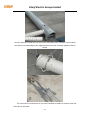
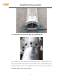
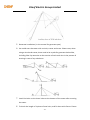
USER’S MANUAL FOR EW‐SERIS
WIND TURBINE


‐1‐
Chenf Electric Group Limited
Warnings:
z
Please excuse from specification alternations without notice;
z
It is required to comply with the local law, regulations or the permission From
local government before installing WTGS;
z
Only under no wind weather should carry out the installation, maintenance
and dismantling of WTGS;
z
Please make sure the construction for WTGS mechanical and electronic
facilities should be done by professionals;
z
Color or figuration of pictures might be varied against physical goods;
z
It is forbidden to leave the wind turbine generator working under unloaded
state (such as without connecting with batteries).
z
The safety signs involving the manual are as followed;
Danger‐‐‐Improper operation might lead to hurt people badly.
Attention‐‐‐Improper operation might lead to damage products or hurt People.


‐2‐
Chenf Electric Group Limited
Contents
1. Abstract .......................................................................................................................... ‐ 3 ‐
2. Application...................................................................................................................... ‐ 4 ‐
4.Installation ....................................................................................................................... ‐ 6 ‐
4.1
Site choosing ............................................................................................. ………………………‐ 6 ‐
4.2. The installation ....................................................................................................................... ‐ 6 ‐
5 The installation of guy cable tower .................................................................................. ‐ 15 ‐
6. Battery Configuration ...................................................................................................... ‐ 24 ‐
7. Electrical wiring ............................................................................................................... ‐ 26 ‐
7.1 Off‐grid solution (please refer to the following diagram). .................................................... ‐ 26 ‐
............................................................................................................................................. ‐ 30 ‐
3 Controller Manual and Operation ................................................................................... ‐ 30 ‐
Press the Fn key in any page, it will jump directly to a specific page, as follows ................ ‐ 31 ‐
9. Maintenance .................................................................................................................... ‐ 38 ‐
10 Trouble shooting ............................................................................................................. ‐ 39 ‐
‐3‐
Chenf Electric Group Limited
1.
Abstract
WTGS could produce electricity by rotating the blades. The controller aims to
rectify the output and protect generator against severe circumstance. The EW‐series
generator could be applied in wind‐solar hybrid system since it has a solar connector.
2.
Application
This WTGS could be applied for home/factory use, which is available for on‐gird
and off‐grid. On‐gird matches on‐grid inverter while off‐gird matches batteries and
off‐grid inverter.
Not available for circumstances as below:
1 No loading
2 Directly connecting with the appliance
‐4‐
Chenf Electric Group Limited
3 Parameter
Model
CFW2000W
CFW3000W
Brand
CHENF
CHENF
Rated power (W)
2000
3000
Max. Power (W)
2500
3450
Rated voltage (V)
48/96
48/96
Rated current (A)
42/21
62.5/31.25
Blade No. (Pcs)
3
3
Rotor diameter(m)
3.2
3.7
Generator type
Permanent magnet
Permanent magnet
Blade material
GFRP
GFRP
Start‐up wind speed(m/s)
2.5
2.5
Rated wind speed (m/s)
12
12
Survival wind speed(m/s)
45
45
Collector ring type
Sealed and waterproof Sealed and waterproof
Controller mode
PLC intelligent control
PLC intelligent control
Operating mode
Auto/Manual
Auto/Manual
efficiency
0.95
0.95
Protection
‐‐Dump load
‐‐Electromagnetic
brake
‐‐Dump load
‐‐Electromagnetic brake
Designed lifetime (years)
15‐20
15‐20
‐5‐
Chenf Electric Group Limited
4.Installation
4.1
Site choosing
WTGS should be installed at least 50m away from house or areas people
gathering. Trees or buildings should not be nearby so as not to affect wind
speed/wind direction. It is forbidden to install on soft lands, uneven ground or areas
where easily be influenced by climates. Meanwhile, the distance between generator
and battery should also be taken into consideration, since longer distance causes
more wastage. Use a thicker cable for connection between long distance if possible .
4.2. The installation
1.
Connection
between
wind
turbine
flange
and
pole
Connect the cable respectively with 6 pcs lines in the head. The cable pierce
from the pole center and short‐circuited with the generator’s 3pcs cables.
‐6‐
Chenf Electric Group Limited
2. Fasten wind generator flange with pole with 6 pcs 12x50mm hex bolts;
3.
The
installation
of
Insert union, bushings and pin onto tail vane by order.
‐7‐
tail
vane
pole
Chenf Electric Group Limited
Then insert the tail vane into rotary sleeve, making U‐groove placed into head
screws
‐8‐
Chenf Electric Group Limited
Finally, fasten union and rotary sleeve with crescent wrench.
4.The installation of tail vane
Insert the tail vane into pole, as below, and fasten with screws.
Note:
fasten round pipe with 5 pcs M10 * 80mm screw‐rudder plate
fasten square steel tube with 6pcs M10 * 110mm screw‐rudder plate
‐9‐
Chenf Electric Group Limited
5. Install the blade flange onto motor shaft, as below, the long head is outward.
‐ 10 ‐
Chenf Electric Group Limited
6. Pierce 12 pcs M10 * 70mm screws into wear plate, and then fasten screws the
blades onto positioned plate.
7. Fasten blade flange with M24mm nut, meanwhile, rotate blades clockwise until
the blade flange is tightened with motor shaft ;
‐ 11 ‐
Chenf Electric Group Limited
8. Place nose cone into blades, and fasten it in the front of generator with
M6x60mm hexagon socket screws;
After the assembling, the physical digram is as below:
‐ 12 ‐
Chenf Electric Group Limited
9. The cable wire pierced from wind generator should be connected with controller
terminal.
Three wires of wind turbine should be connected to A, B, C terminals, as below.
The rest six wires should be connected with wiring terminal by order as the digital
above shows.
Note: 1. three wires of collector ring
1 (red)
2 (yellow)
3 (black)
2. three wires of anemometer
4 (red)
5 (black)
6 (yellow)
The red switch on control cabinet function as emergency stop, in
non‐emergency or a PLC fault, please do not press the switch, in case it may damage
the generator. After unpacking, check that the emergency switch is pressed or not. If
pressed, rotate the button as the switch arrow shows. Then PLC can work.
‐ 13 ‐
Chenf Electric Group Limited
‐ 14 ‐
Chenf Electric Group Limited
5 The installation of guy cable tower
5.1 Foundation sizing
Please install the generator only under no wind weather.
To make the foundation in an open area
Model
Foundation
Radius( m)
Center foundation( m)
Edge foundation ( m)
5KW
Guy cable tower
6
0.9*0.9*1.2
0.8*0.8*0.9
5.2 Anchor arrangement and pouring foundation
Please dig the basement according to the designed size, and then put the anchor in
the basement. Assemble the plate as below. It needs three screw holes forwards to
the front side.
‐ 15 ‐
Chenf Electric Group Limited

Pour the concrete after the anchor and basement are laid down(C25), picture
as below.

Put the edge anchor into the edge basement, and check the distance between
the hook and the center as well as the basic level, and then pour the concrete.
Picture is as below.

‐ 16 ‐
Chenf Electric Group Limited

To keep the balance of the tension between each cable, the height of the basement
need to be equal with the base of the tower. Otherwise, the unbalance would cause
damages for the tower.
5.3 Assemble the tower
Connect the two section of subsidiary pole together, and insert it into the main tower,
as below

‐ 17 ‐
Chenf Electric Group Limited

Connect 4 pieces of steel wire to the end of subsidiary pole, and then connect steel
wire which corresponding to the edge basement with the U‐shape spend orchid, as
below,

The steel which corresponds to the front basement needs to connect with the
chain block, as below.
‐ 18 ‐
Chenf Electric Group Limited

Erect the subsidiary pole, and fix steel wire to the edge basement, as below.

Aim the pin hole of tower to the basement, and insert the pin with smearing
grease, as below.
‐ 19 ‐
Chenf Electric Group Limited

1. Connect each section of the pole by screw as below.

2. To connect the steel wire after connecting the tower as below picture. For
safety, you could twine the tower with the steel wire for a circle before fixing the
wire with the fixture. There need to be two fixtures for each steel wire, and 10‐20
cm need to be left in the end of the wire.
‐ 20 ‐
Chenf Electric Group Limited

3. Besides aiming the steel wire for front basement, the ends of all other steel
wire need to connect with the corresponding basement. And you could fix all
wires after the installation of the tower as below

4. Put the tower on a wooden yoke with the height of 1m to 1.5m, as below.
‐ 21 ‐
Chenf Electric Group Limited

5. Generator installation ( In the manual for generator part)
6. You could erect the tower with a winch, tractor and crane. Please note, when
using a winch and tractor, there need to be a yoke for generator below 2kw,
including 2kw. Pay attention to the tension of each steel wire in the process of
erecting in case of any unbalance.

7. Install the bolts to the three holes at the bottom of the tower after erecting
the tower.
8. To check the length of 4 pieces of steel wire, and fix them with fixture. Please
‐ 22 ‐
Chenf Electric Group Limited
note that a proper radian should be left for the steel wire.
9. You need to take the subsidiary pole away and release the steel wire after
installation.
5.4 Lay down the tower
Under on wind weather should lay down the tower, and prepare a yoke (which is
the same in installing).
(1)Disconnect the electrical connection so as to stop the generator, which
could be referred to the user’s manual.
(2)【If using a crane】The harness should be tied to the generator by
professional people. And then release the screw and steel wire to lay down the
generator slowly to the yoke.
z
【If using a tractor or winch】Firstly release the steel wire of the basement,
and then connect the steel wire to tractor or winch according to the installing
manner by reversing it. Finally, lay down the tower on the yoke slowly.
‐ 23 ‐
Chenf Electric Group Limited
6. Battery Configuration
Battery bank should be put in building where is broad and ventilated with stable
temperature and dry air. Output voltage of battery will decide
battery NO. and
decide connection in series or parallel, and then design the shelf to place batteries,
controller and inverter. To connect batteries in parallel or series according to the
requested capability and voltage, and grease all the wire heads with butter or other
anti‐corrosion material. To avoid the interference of electro magnet, the lead
between battery and controller should be less than 3 meters.
Please refer to model and parameter table for the suggested battery capability.
Series connection is to connect the anode of one battery to the cathode of the
other in consecutive. The graph as follow (the red position is the anode of the battery,
and the blue position is the cathode of battery)

Parallel connection is to connect the anode of one battery to the anode of the
other, and the cathode of one battery to the cathode of the other.
‐ 24 ‐
Chenf Electric Group Limited

※Please check the no fica on, instruc on and maintenance with BATTERY
INSTRUCTION.
‐ 25 ‐
Chenf Electric Group Limited
7. Electrical wiring
7.1 Off‐grid solution (please refer to the following diagram).

Make sure that the voltages among the wind turbine output, battery bank and
inverter input should be the same. Please do not mistakenly connect the position
cathode and the negative cathode, which might burn down the generator,
batteries or inverter.
7.2
On‐grid solution (please refer to the following diagram).

‐ 26 ‐
Chenf Electric Group Limited
Every model could be applied for on‐grid system with the permission of local
government, and on‐gird inverter and on‐grid controller should be purchased by your
own part.
Please turn off the main supply before connection.
‐ 27 ‐
Chenf Electric Group Limited
8 Controller instruction and operation
1. Introduction
Intelligent wind turbine controller can measure wind speed, voltage, current,
temperature and other parameters, and display through LCD screen. According to
relevant parameter values set by the user, controlling automatically controller
unloading and braking to prevent damage of wind turbine. If it’s wind‐solar controller,
when detecting the battery voltage is too high, the controller will automatically
disconnect solar and battery to prevent battery overcharge and damage.
2. system components
2.1 Sensor
Sensor includes:
1. wind speed sensor: controller uses it to monitor wind speed.
2. Thermostat: controller uses it to control the temperature of the wind turbine and
does not show the temperature. wind turbine will unload brakes when the motor
reaches temperature protection.
‐ 28 ‐
Chenf Electric Group Limited
3 voltage, current, speed acquisition: Monitoring the generator voltage, the intensity
is converted to weak current after connecting PLC.
Monitoring of solar charge current, charge current fan.
Note: Do not directly connecting the generator voltage with PLC controller,
otherwise it will seriously damage the controller.
(4)Controller
The controller is Xinje PLC machine, and installed in the strong electric cabinet.
It is as the generator controller after processing the collected data through the use of
sensor. Software control has 2 unloading operation, 1 circuit brake, 1 solenoid brake.
Short‐circuit brake is fail‐safe, it means when the PLC faults or PLC is power‐off,
automatic braking, to avoid excessive speed of wind turbines and cause coaster.
The communications between PLC and PC are half‐duplex 485 (three lines, A, B,
ground). In the internal PLC, the communication and micro‐computer controller part
has realized electrically isolated, effectively improving the noise immunity of
communication.
‐ 29 ‐
Chenf Electric Group Limited
3
Controller Manual and Operation
3.1 Related defination
Brakes: When the wind speed, voltage, temperature are beyond the limit, the brake
relay, the wind turbine stops rotating to protect itself.
Unloading: When the wind speed and voltage overrun, PLC will discharge excessive
energy through unloading circuit by controlling the contactor.
3.2 Man‐machine interface operation:
(A) monitor is connected with the power, and displays the main page when booting
Press the ALM key to switch working status
(2) Only in manual mode can be carried out following operation
‐ 30 ‐
Chenf Electric Group Limited
Only in this page can "0", "1", "2", "3" work.
(3) Press
in any page and enter the parameter setting mode, at that time you
can enter the setting value on digital panel, then press
Press
to clear and re‐enter if there are errors,
to complete the setup.
can also be entered to
unset, and then re‐enter the setting status.
In the non‐setting state,
,
can be entered to select the page
Press the Fn key in any page, it will jump directly to a
specific page, as follows
Press F1 to enter the home page
This page displays: battery voltage, wind turbine current, wind turbine power.
‐ 31 ‐
Chenf Electric Group Limited
Press
to view the page of running status
This page displays: Solar current, solar power, wind speed, rotating speed.
Press
to view the parameter setting of solar
Sig\Low:Lower sensor signal current of solar energy
Sig\Up:maximum sensor signal current of solar energy
Curt\Low: Lower current of solar energy
Curt\Up:maximum current of solar energy
Then
to view the page of current parameter of wind turbine
Sig\Low:Lower sensor signal current of wind turbine
Sig\Up:maximum sensor signal current of wind turbine
Curt\Low: Lower current of wind turbine
Curt\Up:maximum current of wind turbine
‐ 32 ‐
Chenf Electric Group Limited
Press F2 to enter the page of over‐voltage protection parameter
Electromagnetic brake protection:
Maximum electromagnetic: When the battery voltage reaches the setting value, the
electromagnetic brake relay starts.
Backlash: When the rotating speed is reduced to this setting value, the electromagnetic brake
stops.
Short‐circuit brake protection:
Maximum Short‐circuit: When the battery voltage reaches the setting value, the short‐circuit
brake relay starts.
Backlash: When the battery voltage drops to this setting value, the short‐circuit brake stops.
Unloading 1 protection:
Maximum unloading 1: when the battery voltage reaches this setting value, unloading 1 relay
starts.
Backlash: When the battery voltage drops to this setting value, the unloading 1 stops.
Unloading 2 protection:
Maximum unloading 2: when the battery voltage reaches the setting value, unloading 2 relay
starts.
Backlash: When the battery voltage drops to this setting value, the unloading 2 stops.
Press
to enter the setting page of over‐charge protection.
‐ 33 ‐
Chenf Electric Group Limited
Relay start: When the electromagnetic brake starts beyond the setting time, short‐circuit brake
starts.
Relay Stop: When the voltage declines, short‐circuit brakes stops beyond the setting time.
In this page, press
to enter solar and fan protection setting
solar\Up: Maximum solar protection. When the battery voltage exceeds the setting value, and
the solar relay starts work, then the solar disconnects with battery to prevent battery
over‐charge.
solar\Low: Lower solar protection. Battery voltage below the setting value, the solar relay stops
working.
Fan close delay: The delay for fan to close. The time for wind turbine to continue working as soon
as load protection stops.
Press F3 to enter the page of wind speed protection parameter
‐ 34 ‐
Chenf Electric Group Limited
W.S.\UP:Maximum Wind speed. when the wind speed reaches this set value, the controller
starts braking and unloading protect.
RPM\Hys:Rotating Speed Backlash.In the status of wind speed protection, when the speed drops
to this setting, the electromagnetic brake stops.
W.S.\Hys:Wind Speed Backlash: When the wind speed dropped to this setting, brakes and
unloading relay stop working.
Short Brk delay:Short‐circuit brake delay: in the status of wind speed protection, when it is
over‐speed, starts the electromagnetic brake , and then starts short brake beyond this setting
time.
Press F4 to enter the page of over‐temperature setting
TEMP Signal:Temperature signal. When the temperature is too high, indicator will turn to black.
ELEC Brk delay: The time for electronic brake delay. When the temperature is too high, the
electronic brake delay starts at setting time.
re‐brake delay:The time for short‐circuit re‐brake delay. When the temperature is too high, the
temperature dropped to normal, short‐circuit brakes continue to work.
Press F5 to enter the page of rotating speed protection
‐ 35 ‐
Chenf Electric Group Limited
Rotate\UP:Maximum Rotating speed. When it reaches the setting value of rotating speed, starts
brakes and unloading protection.
Rotate\Hys:Rotating speed Backlash. When it drops to this rotating speed, stops brakes and
unloading.
W.G. Pole:Wind turbine generator pole
Press F6 to enter the page of current protection
C\UP:Maximum Current. When it reaches the setting value of current, starts brakes and
unloading protection.
C\Hys:Current Backlash. When current drops to this rotating speed, stops brakes and unloading.
Press F7 to enter the page of battery voltage parameter
‐ 36 ‐
Chenf Electric Group Limited
Sig\Low:Lower voltage of sensor signal
Sig\Up: maximum voltage of sensor signal
Vot\Low:Lower voltage of battery
Vot\Up: maximum voltage of battery
Press F8 to enter the page of manual protection
In the home page, when control mode switch into manual mode, press "0", "1", "2", "3" to carry
out the protection.
Short Brk:Press “0” in this page, and start short brake protection.
ELEC Brk:Press “1” in this page, and start electronic brake protection.
Load1:Press “2” in this page, and start load1 protection.
Load2:Press “3” in this page, and start load2 protection.
Waring:
When the temperature, voltage, wind speed is too high, man‐machine interface will report
warnings to remind the owners.
Press
to disarm the alarm when alarm reports.
Note: All parameters have factory set, please do not modify the parameters. Please contact the
‐ 37 ‐
Chenf Electric Group Limited
manufacturer if modify !
9. Maintenance
Please check and maintain the generator regularly because the environment for
generator might be very serious. It is suggested to lay down the tower before storm
coming in case of any damage.
No
Item
.
1
Check blades: look for cracks or abnormal bends. If
After
storm
√
Every
Every Every 5
Month Year
year
√
you locate any damage caused by storms or
weather, replace the blades as using damaged or
unbalanced blades will compromise the efficiency
and lifetime of the windmill.
2
Grease ball bearings.
√
3
Check if nuts and bolts have remained tight on mill √
√
and tower.
4
Check electric power cables for corrosion and
√
√
damage. If you detect any abnormal corrosion,
replace cables.
5
√
To repaint the tower if the painting drops caused by
climate.
6
7
To check if the control system is working well.
√
To check the electrolyte level of battery and add if
√
not enough by following
instruction.
‐ 38 ‐
Chenf Electric Group Limited
10 Trouble shooting
1. Why doesn't the electric equipment work normally after connecting to wind
system?
Please check the left energy of batteries, because the equipment can't work
smoothly if energy is not enough. But if it is enough, make sure whether the wiring
between batteries and inverter is correct.
2. Why can't the batteries be charged?
Check whether the blades are turning or not, because generator has no output at too
high or too low wind speed. But if the blades are running normally, please disconnect
cables of batteries and inverter at first, then check the output of generator with
voltage meter. If the output is in gear, please examine the batteries works or not. If
the output is zero, please check the cable of generator.
3. Why can't the blades turn at a normal wind speed?
If the wire of generator output is short‐connected, and the blades don't work, please
disconnect the cables of batteries and inverter, and then check the generator's
cable.
4. Whether the using time of electro‐equipment can be prolonged through enhancing
the capacity of batteries?
If the suggested batteries capacity is increased, it will cause a lacking energy for long
time, which influences the life‐span of batteries and leads waste.

Please contact with our engineer by e‐mail/mobile if you cannot solve the
problem.
* Color of the pictures might be varied against physical goods;
* Please excuse from specification alternations without notice;
* Two‐year warranty is offered from the purchasing date(natural disaster or force
majeure should excluded from the warranty)
‐ 39 ‐
Chenf Electric Group Limited

‐ 40 ‐