1
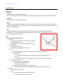
XIV.A. Operation of Systems References: FAA-H-8083-23; FAA-H-8083-25; FAA-H-8083-3; POH/AFM Objectives The student should develop knowledge of the elements related to the DA42 systems and their operation as required in the PTS. Key Elements 1. Semi-monocoque Construction 2. Thielert TAE 125-01 Diesel Engines 3. ECU’s/FADEC Elements 1. 2. 3. 4. 5. 6. 7. 8. 9. 10. Primary Flight Controls and Trim Flaps Powerplant and Propeller Landing Gear Fuel System Electrical Avionics Pitot Static System Environmental Deicing and Anti-Icing Schedule 1. 2. 3. 4. Discuss Objectives Review material Development Conclusion Equipment 1. White board and markers 2. References IP’s Actions 1. 2. 3. 4. SP’s Actions 1. Participate in discussion 2. Take notes 3. Ask and respond to questions Completion Standards The student understands the operation of the systems in the DA42 aircraft. Discuss lesson objectives Present Lecture Ask and Answer Questions Assign homework XIV.A. Operation of Systems Instructors Notes: Introduction: Attention Interesting fact or attention grabbing story The inner workings of the airplane; to develop a better understanding of what is what, and what is where. Overview Review Objectives and Elements/Key ideas What The main systems found on the DA42. This includes the primary flight controls and trim, flaps, powerplant, propeller, landing gear, fuel, oil and hydraulic systems, electrical and avionics systems, flight instruments and the environmental system. Why Understanding how the airplane works internally will allow for better troubleshooting and problem identification. The pilot will have a better understanding of the airplane as a whole and the ability to make a more competent go/no go decision. How: 1. Primary Flight Controls and Trim A. Ailerons i. Glass Fiber Reinforced Plastic/Carbon FRP Sandwich ii. Actuated via push rods iii. Attached with stainless steel and aluminum hinges B. Elevator (GFRP) i. Actuated via push rods ii. Semi-Monocoque sandwich construction iii. Trim a. Mechanical (wheel on center console) & Electrical (rocker switch) Systems b. Two actuating Levers Left Lever a Connects to long flexible cable that is adjusted by the pilot to adjust trim Right Lever a Friction Damper to prevent fluttering if mechanical failure of the trim cable iv. Variable Elevator Stop a. Limits elevator up movement when: Both engines exceed 20%, AND Flaps are set to landing b. Used to prevent over rotation during a go around Apparently there was an excessive left turning tendency they wanted to limit C. Rudder i. Actuated via control cables ii. Trim a. Controlled with black wheel on center console Flexible cable connects it to trim tab 1 XIV.A. Operation of Systems iii. Semi-Monocoque sandwich construction 2. Flaps A. GFRP/CFRP Sandwich B. 2 section construction i. Outer Flap: 6 hinges ii. Inner Flap: 4 hinges iii. Each section has its own push rod (4 total) iv. Fail Safe Construction: Inner & outer are connected which prevents a split flap condition a. If one push rod breaks on either side all flaps will still deploy (no split flap) C. Driven by an electric motor i. Electric flap actuator is protected by a circuit breaker (5 Amp) a. Located on the R side of the instrument panel and can be manually tripped to disable the system D. Controlled by 3 position flap operating switch on the instrument panel i. Top position – Up – 0o (Green Light) ii. Middle Position – Cruise – 20o (Yellow Light) - 137 knots iii. Bottom Position – Landing – 42o (Yellow Light) -111 knots iv. When two lights are illuminated at the same time, the flaps are in-between positions 3. Powerplant and Propeller A. Powerplant i. Thielert Diesel TAE 125-01 engines a. 135 hp @ 2300 rpm b. 4 cylinder c. 4 stroke d. Liquid Cooled e. Turbocharged f. Reduction gear to Propeller g. Wet Sump Oil system ii. Diesel Engine a. Typically turbocharged to ensure compression/temperatures in combustion chamber No spark plugs, air/fuel mixture combusts due to high pressure and temperature b. Diesel/Jet A fuel contains more energy than avgas More fuel efficient/cleaner iii. Common Rail Injection a. High pressure reservoir of fuel which feeds injectors iv. Turbocharged a. Ensures air is properly compressed for combustion Air is compressed in the compressor, then sent to the intercooler a Intercooler cools the hot compressed air 1. Cooling further compresses the air for more power Then it is sent to the combustion chambers The exhaust is ducted back to spin the compressor b. Compressor Engine exhaust air is used to run the compressor Wastegate a Gate that opens or closes to allow more of less exhaust gas to run the compressor 1. More air = More compression 2. Less air = Less Compression 2 XIV.A. Operation of Systems b Adjusts to maintain engine manifold pressure based on altitude B. Propeller i. General a. Wood covered in GFRP b. Constant Speed, Fully Feathering ii. Gearbox a. Ratio of 1.69:1 Engine spins 1.69 rpm to every 1 prop rpm b. Gearbox has its own oil system (separate from engine) iii. Constant Speed Unit (CSU) a. Since there’s no RPM lever the CSU adjusts prop pitch for you b. Oil pressure is used to move a piston which in turn adjusts the pitch of the blades Increasing oil pressure = more fine pitch (flatter blade angle) Decreasing oil pressure= higher pitch If oil pressure is lost the props will auto feather a This happens only when RPM is > 1300 b If below 1300 RPM (like on normal shutdown) the Coarse Pitch Stop will prevent feathering 1. Props won’t feather on normal shutdown iv. Accumulator a. Stores pressure at 290 psi (nitrogen and oil charge) Uses pressure to unfeather prop when restarting in air Maintaining RPM as engine slows a To keep a constant rpm as engine slows (in a climb, etc.) the blade angle needs to get finer (more oil pressure is needed on piston). If it cannot accomplish this under normal circumstances the accumulator will use its stored oil pressure to further decrease blade angle C. Engine Cooling i. Water based with antifreeze ii. Two circuit system a. Main circuit cools engine b. Bypass circuit for when engine temperature is cold D. Engine Control Unit i. Heart of the FADEC – Monitors, controls and regulates all important parameters ii. 2 ECU’s per engine, an A & B ECU a. A is used for normal operation, B is backup iii. Electrically powered a. Electricity is necessary to run engines iv. Redundant a. Both ECUs are always operational, only one is active If A is not 100% it auto switches to B E. Engine Master Switches i. Powers a. Engine ECUs b. Engine Preheat (flow plugs) c. Unfeathering Accumulator d. Enables starter 3 XIV.A. Operation of Systems e. Connects alternators to excitation batteries F. Oil System i. One oil system for the engine, one for propeller gear box ii. Engine Oil = Wet Sump System a. Means engine oil is stored in the engine b. Dry sump = oil reservoir is outside of the engine and pumped in G. Alternate Air i. Air is drawn from engine compartment ii. One lever opens alternate air for both engines 4. Landing Gear A. General i. Fully retractable, Hydraulically operated, Electrically powered B. Main Gear i. Trailing Link Design ii. Tubular strut with a trailing link at the bottom a. Wheel attaches to trailing link b. Gas/Oil filled damper attaches to rear of tubular steel strut and trailing link C. Nose Gear i. Steel strut w gas/oil damper to absorb shock ii. Steering a. Obtained by rudder control via steering linkage b. Spring assembly centers gear when deflected Nose wheel retracts straight after takeoff D. Hydraulic Supply & Control i. Hydraulic Control Block a. Electric Motor b. Hydraulic Pump and Pressure Switch Pumps hydraulic pressure to extend/retract gear Pressure switch maintains pressure in system a Turns on at 1400 psi and off at 1650 psi c. Hydraulic Reservoir Stores excess hydraulic fluid d. Hydraulic Accumulator E. Gear Operation i. System is always pressurized ii. Electrically operated valves provide hydraulic pressure to move actuators iii. Main gear retracts inboard, Nose gear retracts forward iv. Hydraulic pressure on actuators keeps gear retracted a. No up locks, if hydraulic pressure fails, gear will extend v. If electrical system fails, gear will extend automatically a. Hydraulic pressure will fail without electric power F. Emergency Extension i. Releases hydraulic pressure allowing gear to fall by gravity G. Safety Features i. Squat Switch a. Left main gear leg Prevents gear from retracting on ground 4 XIV.A. Operation of Systems ii. Gear Warning Horn a. Either power lever below 25%, or b. Flaps in Landing Position H. Wheel Brakes i. Hydraulically operated disc brakes ii. Operated individually using toe-brake pedals I. Parking Brake i. Repeated pushing of the toe-brake pedals will build up the required brake pressure, which will remain in effect until the brake is released 5. Fuel System A. Fuel i. 2 main aluminum fuel tanks a. Each tank has 3 chambers joined by hoses b. 25 gallons per tank ii. Auxiliary Tanks a. 2 (optional) 13.2 useable gallon tanks 26.4 Gallons total + 50 Gallon mains= 76.4 useable gallons b. Located in rear of engine nacelle c. Fuel is transferred from Aux to main tanks via pump switch on rear center console iii. Components a. Fuel Selector Each engine has one Settings a On – Normal fuel flow b X-Feed – Engine draws fuel from opposite fuel tank c Off – Turns off fuel to engine b. Indicators Inner and Outer chamber of main fuel tanks have level sensors a Not necessary to have one in middle chamber Low level sensor a Operates at 3-4 USG in tank c. Fuel Cooler Uses heat exchanger to cool fuel before returning it to tank 2-3 times more fuel than is necessary for injectors flows through common rail a Common rail is under tremendous pressure so fuel gets very hot b Excess fuel is returned to engine, but cooled first 1. Prevents vapor lock iv. Operation a. 2 fuel pumps Booster Pump a Sends fuel to high pressure pump High Pressure Pump a Pumps fuel to common rail b. Normal Operation Fuel is drawn from tank into engine, the unused fuel is returned to the tank via fuel cooler c. X-Feed Fuel is drawn from opposite tank into engine, unused fuel is returned to original tank 5 XIV.A. Operation of Systems a Prevents over filling the opposite tank 6. Electrical A. Power Generation i. Two 28V DC, 60 Amp Alternators ii. Belt drive, located on bottom left of each engine iii. Controlled by separate on/off switches on instrument panel Alternator can never actually be turned off, just disconnected from system a Alternator is directly connected to ECU buses, always want power to ECUs iv. Alternator Control Unit a. Balances load between the two alternators based on temperature Colder alternator gets more load v. Excitation Batteries a. Two 12 V, 1.3 amp-hr. lead acid batteries b. Used to get alternators started c. Also used to sustain the alternator if it cannot generate a magnetic field B. Power Storage i. Main Battery a. 24 V, 10 A-hr., lead acid battery b. Located rear-right side of front baggage compartment ii. Emergency Power Pack a. 10 non rechargeable dry lithium manganese batteries b. 3 V, 1300 mA-hr. c. Runs backup AI and flood light for at least 1.5 hrs. In the case of electrical failure and main battery failure d. Controlled by emergency switch iii. ECU Backup Batteries a. In the case of total electrical failure the ECU backup batteries will provide power to the ECUs to keep the engines running C. Power Distribution i. Main Battery connects to Battery bus a. Battery bus connects to LH/RH main bus ii. LH Main Bus a. Connects to L Alternator b. LH ECU Bus iii. RH Main Bus a. Connects to R Alternator b. RH ECU Bus c. Avionic Bus 7. Avionics A. G1000 i. G1000 info can be found in the user’s manual B. PFD i. Contains primary instruments C. MFD i. Navigation and Engine instruments 8. Pitot-static System A. Pitot-Static i. Pitot pressure is measured on the leading edge of a calibrated probe below the left wing 6 XIV.A. Operation of Systems ii. Static pressure is measured by the same probe iii. Instruments a. G1000 takes input from the pitot & static pressure probe and converts it digitally 9. Environmental A. Cabin Heat and Defrost i. Cabin Heat is ducted from heat exchanger in the right engine nacelle ii. Defrost is ducted from heat exchanger in the left engine nacelle 10. Deicing and Anti-Icing A. General i. Weeping wing protection a. Distributes a thin film of deicing fluid over wing, vertical stabilizer, horizontal stabilizer, propeller, and canopy ii. Components a. Tank Holds 7.9 Gallons Low level sensor (45 min) Located in Nose b. Pumps 2 main pumps a Used for Wings, Stabilizers and Props 2 Windshield pumps iii. Modes a. Normal Operates with switch to Norm Both main pumps operated simultaneously Use prior to accumulation Pumps cycle: On for 30 sec, Off for 90 sec Max Duration: 2.5 hrs. b. High Operates with switch to High One pump runs continuously Use when ice has accumulated Max Duration: 1 hr. c. Max Operates by Max button Both pumps run continuously Used in severe icing conditions Runs both pumps for two minutes Max duration 30 min iv. Windshield Push Button a. Activates selected pump for 5 seconds (even if main system switch is off) v. Alternate Switch a. If LH Main Bus is lost (Ice system is on LH Main Bus) Flip Alternate switch to connect system to RH main bus a Operation only works in high mode Conclusion: 7 XIV.A. Operation of Systems Brief review of the main points A thorough understanding of the airplane’s systems makes a safer, smarter pilot. PTS Requirements: To determine that the applicant exhibits instructional knowledge of the elements related to the operation of systems, as applicable to the multiengine airplane used for the practical test, by describing at least five (5) of the following systems: 1. Primary flight controls and trim 2. Flaps, leading edge devices, and spoilers 3. Water rudders 4. Powerplant and propellers 5. Landing gear 6. Fuel, oil, and hydraulic system 7. Electrical 8. Avionics 9. Pitot static/vacuum system and associated instruments 10. Environmental 11. Deicing and anti-icing 8