1
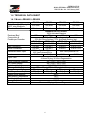
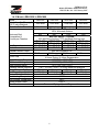
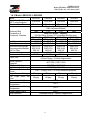
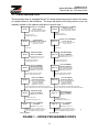
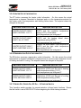
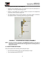
ZEH External Heat Regenerated Compressed Air Dryer
For MODELS ZEH400 TO ZEH3500
This dryer configuration includes equipment
options as selected (X) below:
EC OPTION
LDP OPTION
3V OPTION
This manual is part number
Z103160 Rev. 05
USER MANUAL
Models ZEH400 to ZEH3500 with EC
Z103522 Rev. 06 – 28 February 2007
FOREWORD
Reading this user manual will fully familiarize you with the Zander adsorption dryer.
You will be better able to run this equipment in accordance with its intended use.
This manual contains important information for safe, proper and economic dryer
installation, start-up, operation and maintenance. Always keep it within reach where the
adsorption dryer is being used.
It is necessary to follow all instructions as written. Careful reading will avert danger,
avoid unnecessary downtime, and minimize work for yourself and wear on the
equipment.
In addition to carefully reading this technical manual in its entirety, you must understand
your National, State and local rules and regulations regarding safety in the workplace,
their necessary precautions and procedures.
Each person responsible for the set-up, start-up, operation, maintenance or repair of
this adsorption dryer must have first read and understood this user manual – including
all the safety tips.
NOTE: Zander recommends that installation, start-up and maintenance be
carried out by its factory-trained technicians in a regularly scheduled,
site-dedicated program. This will ensure the safety of personnel, the
integrity of equipment and the surety of warranty coverage.
i
USER MANUAL
Models ZEH400 to ZEH3500 with EC
Z103522 Rev. 06 – 28 February 2007
II
USER MANUAL
Models ZEH400 to ZEH3500 with EC
Z103522 Rev. 06 – 28 February 2007
TABLE OF CONTENTS
1. INTRODUCTION ..................................................................................................................................................1
1.1 GENERAL .............................................................................................................................................................1
1.2 PRODUCT INFORMATION ......................................................................................................................................1
1.2.1 Pressure Vessel Regulations........................................................................................................................2
1.2.2 Leak Test......................................................................................................................................................2
1.3 SAFETY INSTRUCTIONS ........................................................................................................................................2
1.3.1 Identification of Signs and Symbols in this Manual.....................................................................................2
1.3.2 General Safety Tips for Assembly, Inspection and Maintenance.................................................................3
1.4 TECHNICAL DATA SHEET .....................................................................................................................................4
1.4.1 Models ZEH400 to ZEH820 ........................................................................................................................4
1.4.2 Models ZEH1000 to ZEH1800 ....................................................................................................................5
1.4.3 Models ZEH2100 to ZEH3500 ....................................................................................................................6
1.4.4 Dryer Flow Capacities.................................................................................................................................7
1.5 OVERLOADING .....................................................................................................................................................8
1.6 TRANSPORT .........................................................................................................................................................8
1.7 STORAGE .............................................................................................................................................................8
1.8 USE OF A PREFILTER AND AFTERFILTER ..............................................................................................................8
2. INSTALLATION....................................................................................................................................................9
2.1 GENERAL .............................................................................................................................................................9
2.2 MECHANICAL ASSEMBLY ....................................................................................................................................9
2.3 FILTER INSTALLATION .......................................................................................................................................10
2.3.1 Prefilter Installation (Shipped Loose) .......................................................................................................10
2.3.2 Afterfilter Installation (Shipped Loose) .....................................................................................................11
2.3.3 Filter Skid with 3 Valve Bypass (If Dryer Includes 3V Option).................................................................11
2.4 ELECTRICAL CONNECTION.................................................................................................................................11
2.5 EC CONTROL CONNECTION ...............................................................................................................................12
3. EQUIPMENT OPERATION ..............................................................................................................................13
3.1 GENERAL OPERATING PRINCIPLES .....................................................................................................................13
3.1.1 Dryer Program Steps.................................................................................................................................14
3.2 OPERATOR CONTROLS / LOW-VOLTAGE CONTROL PANEL ................................................................................15
3.2.1 Dryer Status...............................................................................................................................................16
3.2.2 Alarm Information .....................................................................................................................................17
3.2.3 Dryer Operation Modes.............................................................................................................................18
3.2.4 Heater Sheath Information ........................................................................................................................18
3.2.5 Heater Outlet Information .........................................................................................................................19
3.2.6 Regeneration Outlet Information...............................................................................................................19
3.2.7 Dryer Off, Dryer On, EC On – 3-Position Switch ....................................................................................19
3.2.8 Status Lamps..............................................................................................................................................20
3.2.9 Pressure Gauges........................................................................................................................................20
3.3 INITIAL START-UP .............................................................................................................................................20
3.3.1 Pressurizing Dryer.....................................................................................................................................20
3.3.2 Energizing Dryer Controls ........................................................................................................................21
3.3.3 Pressure Switch Adjustment.......................................................................................................................21
3.3.4 EC Start Up ...............................................................................................................................................22
3.4 SHORT-TERM SHUTDOWN .................................................................................................................................23
3.5 SHUTDOWN IN CASE OF A FAULT OR FOR MAINTENANCE .................................................................................24
3.6 RESTARTING ......................................................................................................................................................24
4. MAINTENANCE..................................................................................................................................................25
4.1 CHECKLIST ........................................................................................................................................................25
4.1.1 Daily Check ...............................................................................................................................................25
4.1.2 Weekly Check..............................................................................................................................................25
III
USER MANUAL
Models ZEH400 to ZEH3500 with EC
Z103522 Rev. 06 – 28 February 2007
4.1.3 Quarterly Check (Every Three Months).....................................................................................................25
4.1.4 Annual Check.............................................................................................................................................26
4.2 CHANGING THE FILTER ELEMENT ......................................................................................................................26
4.3 REPLACEMENT OF THE DESICCANT ....................................................................................................................27
5. PARTS LIST ..........................................................................................................................................................29
5.1
5.2
5.3
5.4
PARTS FOR ZEH400 TO ZEH650 .......................................................................................................................29
PARTS FOR ZEH820 TO ZEH1225 .....................................................................................................................30
PARTS FOR ZEH1500 TO ZEH2100 ...................................................................................................................31
PARTS FOR ZEH2500 TO ZEH3500 ...................................................................................................................32
6. FAULTS AND TROUBLESHOOTING.............................................................................................................35
6.1
6.2
6.3
6.4
DEWPOINT HAS DETERIORATED ..............................................................................................................35
HIGH HUMIDITY ALARM OR SENSOR FAILURE.....................................................................................36
PRESSURE DROP TOO HIGH........................................................................................................................36
SWITCHING FAILURE ALARM ...................................................................................................................36
7. DRAWINGS..........................................................................................................................................................39
IV
USER MANUAL
Models ZEH400 to ZEH3500 with EC
Z103522 Rev. 06 – 28 February 2007
1. INTRODUCTION
1.1 GENERAL
This adsorption dryer includes the latest technology and safety features. Its use,
however, can endanger life and limb and can lead to considerable damage to the
equipment and other material assets if:
•
it is operated by personnel not instructed in its use,
•
it is improperly used,
•
it is improperly maintained or serviced.
Furthermore, ignorance of its use and maintenance can result in the loss of any claim
for damage.
This adsorption dryer is designed for neutral media (such as air or nitrogen) which is
free of aggressive water, oil and solid elements. Zander accepts no liability for
corrosion damage or malfunctions caused by aggressive media.
Applications other than those mentioned in this manual must be agreed to by Zander
and confirmed in writing.
Zander reserves the right to make changes at any time as may be necessary for
increasing safety or efficiency, or in the interests of further product development.
1.2 PRODUCT INFORMATION
The adsorption dryer is used for the purpose of drying compressed air and other gases
according to its contracted design. Depending on certain conditions at the inlet, and
with pre- and afterfilters properly installed, it provides pure, dry and oil-free compressed
air or gases. The standard model of adsorption dryer is equipped with two desiccant
vessels.
This specific model of dryer includes the Ecotronic Control (EC) energy management
system to provide automatic monitoring and control of the dry/regenerate cycle to
optimize equipment efficiency. This manual includes references to optionally available
Low Dew Point (LDP) and 3-valve bypass (3V) systems/assemblies which may or may
not be provided. Selected options included with this dryer are indicated on the cover
page by an “X” printed in the box.
1
USER MANUAL
Models ZEH400 to ZEH3500 with EC
Z103522 Rev. 06 – 28 February 2007
1.2.1 PRESSURE VESSEL REGULATIONS
The pressure vessels are designed and built to meet the American Society of
Mechanical Engineers (ASME) standards. They fulfill the test of the certifying procedure
and carry the ASME symbols U or UM.
RANGE OF APPLICATION
Design Pressure
Max: 150 psig
Design Temperature
Max: 500 °F (260 °C)
Min: -20 °F (-29 °C)
1.2.2 LEAK TEST
Each Zander adsorption dryer is subjected to, and passes, a leak test prior to shipment.
1.3 SAFETY INSTRUCTIONS
This manual contains basic tips which must be followed during set-up, operation and
servicing. It is most important that it be read by the assembly technician before
installation and start-up as well as by the specialist/operator in charge. It must always
be within reach at the place where the adsorption dryer is being used.
1.3.1 IDENTIFICATION OF SIGNS AND SYMBOLS IN THIS MANUAL
The safety tips contained in this manual, whose disregard could endanger people and
equipment, are indicated by a general danger sign and the additional markings Danger!
or Attention! or Warning!
Danger! / Attention!
Safety sign in accordance with DIN 4844 - W9
Warning – high voltage!
Safety sign in accordance with DIN 4844 - W8
Safety tips printed directly on the adsorption dryer must be heeded at all times and must
be kept completely legible.
2
USER MANUAL
Models ZEH400 to ZEH3500 with EC
Z103522 Rev. 06 – 28 February 2007
1.3.2 GENERAL SAFETY TIPS FOR ASSEMBLY, INSPECTION AND MAINTENANCE
The purchaser is to ensure that all assembly, maintenance and inspection work is
carried out by personnel qualified to do it.
The personnel involved in assembly, operation, maintenance and inspection must have
the corresponding qualifications to do this work. Areas of responsibility and supervision
of the personnel must be clearly established by the purchaser. Should the personnel
not possess the necessary knowledge, then they must be instructed. If need be, this
training may be carried out by the manufacturer/supplier at the request of the purchaser.
Further, the purchaser is to ensure that all personnel completely understand and follow
the content of this manual.
Attention!
•
Never make structural changes to the adsorption dryer
•
Only use recommended spare parts as listed in section 5
•
Never weld on a pressure vessel or change it in any way
•
Carry out maintenance only when the adsorption dryer is OFF,
depressurized and disconnected from the electric power supply.
Danger!
•
Review the Material Safety Data Sheet (MSDS) provided with the
desiccant when installing or disposing of it
•
Wear protective clothing and goggles when working with the
desiccant
•
If desiccant comes into contact with the eyes, rinse eyes
immediately with a lot of clear water
•
If the desiccant is spilled, clean up without causing swirls of dust
•
In case of fire, there is no restriction on the use of fire extinguishing
material on the desiccant; the reaction with water and foam is
defined as strong
•
A mask must be worn whenever handling desiccant.
3
USER MANUAL
Models ZEH400 to ZEH3500 with EC
Z103522 Rev. 06 – 28 February 2007
1.4 TECHNICAL DATA SHEET
1.4.1 MODELS ZEH400 TO ZEH820
Model
Rated flow @ 100 psig &
100°F inlet conditions
Chamber Outer Diameter
Desiccant Bed
Composition &
Pounds per Chamber
Inlet Connection
Outlet Connection
Standard Electric Rqmt
Heater
Cycle Time
Outlet Pressure Dewpoint
EC Control Setting
High Humidity Alarm
Pressure Switch Setpoints
Purge Pressure Setting
Low Purge Alarm Setpoint
Heater Outlet Setpoint
End Heating Temperature
End Cooling Temperature
Heater Sheath Alarm
Flow Directions
ZEH400
ZEH500
ZEH650
ZEH820
400 scfm
500 scfm
650 scfm
820 scfm
18 inches
18 inches
18 inches
20 inches
Standard (no LDP option):
100% Activated Alumina
272
350
433
660
With LDP option – Layered:
33% Mol Sieve (bottom), 67% Activated Alumina (top).
1st MS: 90
1st MS: 115
1st MS: 143
1st MS: 218
nd
nd
nd
2 AA: 182
2 AA: 235
2 AA: 290
2nd AA: 442
2-in NPT
2-in NPT
2-in NPT
3-in RF FLG
2-in NPT
2-in NPT
2-in NPT
3-in RF FLG
230 Vac/3-phase/60 Hz or
460 Vac/3-phase/60 Hz
460 Vac/3-phase/60 Hz
6 kW
6 kW
8 kW
12 kW
8-Hour Cycle –
4 Hours Drying / 4 Hours Regeneration
-40°F PDP (-100°F LDP)
-40°F PDP (-100°F LDP)
-35°F PDP (-95°F LDP)
PSL – 10 psig / PSH – 30 psig below line pressure
70 psig
65 psig
55 psig
55 psig
60 psig
55 psig
45 psig
45 psig
425°F
180°F
120°F
1000°F
Downward Drying – Upward Regeneration
4
USER MANUAL
Models ZEH400 to ZEH3500 with EC
Z103522 Rev. 06 – 28 February 2007
1.4.2 MODELS ZEH1000 TO ZEH1800
Model
Rated flow @ 100 psig &
100°F inlet conditions
Chamber Outer Diameter
Desiccant Bed
Composition &
Pounds per Chamber
Inlet Connection
Outlet Connection
Standard Electric Rqmt
Heater
Cycle Time
Outlet Pressure Dewpoint
EC Control Setting
High Humidity Alarm
Pressure Switch Setpoints
Purge Pressure Setting
Low Purge Alarm Setpoint
Heater Outlet Set Point
End Heating Temperature
End Cooling Temperature
Heater Sheath Alarm
Flow Directions
ZEH1000
ZEH1225
ZEH1500
ZEH1800
1000 scfm
1225 scfm
1500 scfm
1800 scfm
24 inches
24 inches
28 inches
28 inches
Standard (no LDP option):
100% Activated Alumina
825
990
1055
1320
With LDP option – Layered:
33% Mol Sieve (bottom), 67% Activated Alumina (top).
1st MS: 272
1st MS: 327
1st MS: 348
1st MS: 436
nd
nd
nd
2 AA: 553
2 AA: 663
2 AA: 707
2nd AA: 884
3 in RF FLG
3 in RF FLG
3 in RF FLG
4 in RF FLG
3 in RF FLG
3 in RF FLG
3 in RF FLG
4 in RF FLG
460 Vac/3-phase/60 Hz
17 kW
21 kW
25 kW
28 kW
8 Hour Cycle –
4 Hours Drying / 4 Hours Regeneration
-40°F PDP (-100°F LDP)
-40°F PDP (-100°F LDP)
-35°F PDP (-95°F LDP)
PSL – 10 PSIG / PSH – 30 PSIG below line pressure
70 psig
60 psig
65 psig
70 psig
60 psig
50 psig
55 psig
60 psig
425°F
180°F
120°F
1000°F
Downward Drying - Upward Regeneration
5
USER MANUAL
Models ZEH400 to ZEH3500 with EC
Z103522 Rev. 06 – 28 February 2007
1.4.3 MODELS ZEH2100 TO ZEH3500
Model
Rated flow @ 100 psig &
100°F inlet conditions
Chamber Outer Diameter
Desiccant Bed
Composition &
Pounds per Chamber
Inlet Connection
Outlet Connection
Recommended Prefilter
Recommended Afterfilter
Pilot Air Filter
Standard Voltage
Heater
Cycle Time
Outlet Pressure
Dewpoint
EC Control Setting
High Humidity Alarm
Pressure Switch Set
Points
Purge Pressure Setting
Low Purge Alarm Set
Point
Heater Outlet Set Point
End
Heating
Temperature
End
Cooling
Temperature
Heater Sheath Alarm
Flow Directions
ZEH2100
ZEH2500
ZEH3000
ZEH3500
2100 scfm
2500 scfm
3000 scfm
3500 scfm
30 inches
36 inches
40 inches
40 inches
Standard (no LDP option):
100% Activated Alumina
1485
1722
2310
2805
With LDP option – Layered:
33% Mol Sieve (bottom), 67% Activated Alumina (top).
1st MS: 490
1st MS: 568
1st MS: 762
1st MS: 926
nd
nd
nd
2 AA: 995
2 AA: 1154 2 AA: 1548
2nd AA: 1879
4-in RF FLG 4-in RF FLG
6-in RF FLG
6-in RF FLG
4-in RF FLG 4-in RF FLG
6-in RF FLG
6-in RF FLG
SWH-2750
SWH-2100
SWH-4100
SWH-4100
SWF-2750
SWF-2100
SWF-4100
SWF-4100
SWF-20
SWF-20
SWF-20
SWF-20
460 Vac/3-phase/60 Hz
30 kW
36 kW
43 kW
50 kW
8-Hour Cycle –
4 Hours Drying / 4 Hours Regeneration
-40°F PDP (-100°F LDP)
-40°F PDP (-100°F LDP)
-35°F PDP (-95°F LDP)
PSL – 10 psig / PSH – 30 PSIG below line pressure
60 psig
70 psig
65 psig
60 psig
50 psig
60 psig
55 psig
50 psig
425°F
180°F
120°F
1000°F
Downward Drying – Upward Regeneration
6
USER MANUAL
Models ZEH400 to ZEH3500 with EC
Z103522 Rev. 06 – 28 February 2007
1.4.4 DRYER FLOW CAPACITIES
The specific size/model of your dryer was selected to meet performance requirements
based on an analysis of air supply and demand capacities. The model selection chart
provided following should confirm that this dryer remains suitable for its intended use.
The table following is based on -40oF PDP, 8-hour cycle, activated alumina and average
inlet air flow for non-LDP-equipped dryers with EC. Consult our factory for rated air
flows on LDP-equipped dryers.
MODEL
ZEH400
ZEH500
ZEH650
ZEH820
ZEH1000
ZEH1225
ZEH1500
ZEH1800
ZEH2100
ZEH2500
ZEH3000
ZEH3500
Design
Inlet Air
Pressure
(psig)
150
150
150
150
150
150
150
150
150
150
150
150
Rated inlet air flow (scfm) at given pressures (psig)
(Based upon 100oF inlet air temperature)
60
70
80
90
100
110
120
130
140
220
305
360
460
615
690
785
1010
1095
1480
1685
1900
265
355
435
550
715
825
960
1210
1345
1735
2015
2300
310
400
505
640
805
955
1150
1405
1600
1985
2340
2700
355
460
580
735
920
1100
1275
1610
1835
2270
2680
3095
400
500
650
820
1000
1225
1500
1800
2100
2500
3000
3500
440
550
705
905
1140
1360
1600
1995
2275
2820
3330
3845
480
590
790
990
1255
1490
1730
2190
2500
3100
3645
4195
520
645
850
1070
1325
1610
1875
2375
2700
3355
3960
4570
550
680
905
1150
1420
1735
2010
2535
2890
3585
4235
4890
Higher pressures are optionally available. Consult factory.
To correct for an inlet temperature other than 100oF, multiply dryer capacity by the
temperature correction factor listed below.
CORRECTION FACTOR FOR INLET TEMPERATURE
TEMPERATURE
DEGREES F
Correction Factor
80
90
100
105
110
115
120
1.1
1.1
1.0
0.85
0.69
0.565
0.455
Example: To size for an inlet flow of 950 SCFM @ 105 F and 110 psig.
1. Select model that produce at least 950 SCFM at 110 psig. This case would be the
ZEH1000 which can dry 1140 SCFM.
2. Multiply pressure corrected flow by the temperature correction factor to obtain the
flow of the dryer corrected for pressure and temperature:
1140 X (0.85) = 969 SCFM
3. Confirm model selection. Model ZEH1000 can flow 969 SCFM at the inlet conditions
specified; requirements of 950 SCFM are less: ZEH1000 is correct.
7
USER MANUAL
Models ZEH400 to ZEH3500 with EC
Z103522 Rev. 06 – 28 February 2007
NOTE:
Settings for EC:
Standard Dryers:
EC Control
High Humidity -32°F (-35°C)
-40°F (-40°C)
LDP Dryers:
EC Control -100°F (-74°C)
High Humidity -95°F (-69°C).
1.5 OVERLOADING
Attention! Protect the adsorption dryer from overloading!
The adsorption dryer can become overloaded if:
• The flow volume of the medium to be dried increases
• The temperature of the air at entry and, correspondingly, its
humidity increases
• The minimum operating pressure decreases
• The prefiltration and separation of impurities are not sufficient or the
filter drain fails
• Introduction of oil into the air stream.
1.6 TRANSPORT
Immediately upon delivery of the adsorption dryer, it must be checked for any damage
that may have occurred during transport. If necessary, the damage must be recorded
on the shipping waybill/receipt. Liability for such damage usually rests with the shipper.
Contact Zander to arrange for any required service or replacement parts.
Attention!
For transport within your company site, only the skids of the adsorption
dryer may be used. Lifting at any other points on the equipment will void
the warranty and damage the equipment.
1.7 STORAGE
If the adsorption dryer is to be stored for a long period of time, its place of storage must
be dry and free of dust. The ambient temperature cannot go below 33°F (+1°C).
1.8 USE OF A PREFILTER AND AFTERFILTER
In order to prevent droplets of condensate, oil and dirt from getting into the desiccant, a
Zander prefilter must be installed upstream of the adsorption dryer. Otherwise, an oil
film on the desiccant would reduce the drying capacity. In order to prevent breakdown
in downstream consumers caused by material that has been abraded from the
desiccant bed, a Zander afterfilter must be mounted downstream of the adsorption
dryer. Since no condensate should accumulate in the afterfilter, no automatic drain is
required. Both filters are equipped with an incident monitor (i.e., differential pressure
indicator) to advise of blockage in the filter elements.
8
USER MANUAL
Models ZEH400 to ZEH3500 with EC
Z103522 Rev. 06 – 28 February 2007
2. INSTALLATION
2.1 GENERAL
Ensure that the installation site is free of dust, dirt and litter. The site floor must be level
and strong enough to support the equipment. The site itself must be an heated
environment (minimum 50°F) to ensure proper operation and warranty protection.
Ensure that the Zander adsorption dryer is carried only by its skid base frame. The
adsorption dryer must be positioned so that the side from which it is to be operated is
easily accessible. The upstream piping is to be connected at a slightly downward slope
toward the prefilter. Install isolation valves on the inlet to the prefilter and outlet of the
afterfilter. Also, a bypass pipe with an additional isolation valve should be mounted
around the adsorption dryer to allow for an uninterrupted supply of compressed air
when the adsorption dryer requires maintenance or repair. The bypass assembly may
not be provided (see paragraph 1.2): it is optionally available or can be customer
furnished. If vibration occurs at the installation site, the adsorption dryer skid frame
must be placed onto vibration dampers to avoid desiccant abrasion and degradation.
2.2 MECHANICAL ASSEMBLY
•
The equipment should be located in an area with adequate clearances for
service. An overhead clearance of not less than two feet above each desiccant
tower is required for loading of the desiccant.
•
Remove all protective shipping crates, flange covers, etc.
•
Using the mounting holes provided on the skid, anchor the dryer to a solid, level
foundation designed to support the equipment.
•
Do not hydrostatically test the pressure vessels. All ZEH dryer pressure vessels
and welded piping are hydrostatically tested at 1.5 times the design pressure
after fabrication and before assembly.
•
Desiccant for models ZEH820 and up is shipped loose and must be installed on
site. Refer now to paragraph 4.3 for instructions on installing the desiccant.
•
If the equipment is installed in a high traffic area, protective barriers may be
required to prevent possible damage of equipment and to prevent contact with
hot surfaces.
•
Due to vibration during shipping, some tube fittings may have loosened.
Therefore, inspect all connections and tighten if required.
•
Ensure that the inlet and outlet connections to and from the dryer are made using
the correctly rated fittings and piping to meet the design conditions.
9
USER MANUAL
Models ZEH400 to ZEH3500 with EC
Z103522 Rev. 06 – 28 February 2007
NOTE: System isolation and bypass valves should be installed. If not supplied
by Zander as part of the equipment package (i.e., 3V option – see
paragraph 1.2), they should be supplied and installed by others. Ensure
that this bypass facility is installed so that future servicing of the dryer
system off-line may take place.
•
Full flow relief valves to protect the system from over-pressure must be
customer-provided in accordance with local regulations.
•
The purge exhaust on the ZEH650 and smaller dryers is equipped with an
exhaust muffler/silencer. If required, the silencer can be removed and purge
exhaust can be connected to a vent header. Follow recommendations for pipe
sizing listed below.
•
The purge exhaust connection on the ZEH820 and larger dryers must be
connected to a vent header. To ensure satisfactory regeneration of the desiccant
chambers, the purge exhaust piping should be sized as follows to prevent backpressure build up.
EXTENDED LENGTH
TO 10 FEET
TO 25 FEET
TO 50 FEET
TO 100 FEET
PIPE SIZE REQUIRED
SAME SIZE AS DRYER EXHAUST
1 SIZE LARGER THAN DRYER EXHAUST
2 SIZES LARGER THAN DRYER EXHAUST
3 SIZES LARGER THAN DRYER EXHAUST
Caution!
The noise at the outlet of the exhaust header may exceed 100 dBa, and
the flow velocity will be high. Exhaust must be piped to an area where
these flow velocities and noise levels can be safely tolerated.
2.3 FILTER INSTALLATION
Pre- and afterfilters for the ZEH dryer must be purchased separately. These filters are
available loose, or as part of a separate bypass skid with the 3V Option (i.e., 3-valve
bypass assembly with mounted filters).
2.3.1 PREFILTER INSTALLATION (SHIPPED LOOSE)
•
Mount prefilter in such a way as to allow clearance for the element installation
and removal.
•
Locate the prefilter as close to the dryer inlet connection as possible.
•
The filter must be piped so that the correct flow direction indicated on the filter is
followed.
10
USER MANUAL
Models ZEH400 to ZEH3500 with EC
Z103522 Rev. 06 – 28 February 2007
•
Ensure that all piping and valves are equivalent or larger in size to the dryer inlet
connection.
•
Connect drain port to a condensate collector. Use an easily visible collector to
aid in operational inspection.
2.3.2 AFTERFILTER INSTALLATION (SHIPPED LOOSE)
•
Mount afterfilter in such a way as to allow clearance for the element installation
and removal.
•
The filter must be piped so that the correct flow direction indicated on the filter is
followed.
•
Ensure that all piping and valves are equivalent or larger in size to the dryer inlet
connection.
2.3.3 FILTER SKID WITH 3 VALVE BYPASS (IF DRYER INCLUDES 3V OPTION)
•
Filters skid should be located as close to dryer as possible. Use the skid bolt
holes to secure the assembly.
•
Ensure that the skid is located such that the 3-valve bypass will bypass the dryer
and filters when in use.
•
Check the flow direction of each filter to ensure the prefilter is connected to the
inlet pipe of the dryer and afterfilter is connected to the outlet pipe of the dryer.
•
Connect the filter skid piping and dryer skid piping using materials and fabrication
procedures that are suitable for compressed air pressure piping. All flanges are
ANSI B16.5 Class 150 raised face flanges.
2.4 ELECTRICAL CONNECTION
Warning – high voltage!
Be sure that power is removed from the line feed before making
connection between the site drop and the equipment.
•
Connect the dryer to a correctly sized power supply. Refer to the dryer
nameplate or the electrical drawing (see section 7) for the supply voltage and
amperage requirement to properly size the electrical service. Only one electrical
connection is required. All internal wiring was done at the factory.
NOTE: A disconnect switch is not provided with the dryer and must be supplied
by the customer in accordance with the local electrical codes.
11
USER MANUAL
Models ZEH400 to ZEH3500 with EC
Z103522 Rev. 06 – 28 February 2007
•
Ground the frame of the dryer in accordance with the local electrical codes.
•
It is recommended that the common alarm relay, located in the dryer control
panel, be connected to the control room or operator station so that an immediate
response to a dryer alarm may be given when required.
•
Before energizing the electrical circuit, the electrical heater assembly should be
inspected to determine that no moisture has accumulated in the heater enclosure
or terminations. A 1000V meg-ohmmeter should be used to determine the
phase-to-ground insulation resistance for each phase. A minimum value of 500
kohms should exist.
2.5 EC CONTROL CONNECTION
•
A probe sample line must be run from downstream of the afterfilter.
•
A 10-ft length of 1/8-in stainless steel tubing and necessary compression fittings
are provided.
•
Tube fittings are to be installed downstream of the afterfilter at the incident
monitor/differential pressure indicator (DPI) port T-fitting on the afterfilter outlet
nozzle
•
Remove the hexagonal plug from the DPI T-fitting.
•
Insert 1/8-in tubing into compression fitting and tighten.
•
Run the tubing back to the hygrometer housing. Cut to necessary length and
connect to the upper connection fitting. Tubing is semi-flexible so care must be
taken when bending to ensure the tubing does not kink.
•
If the sample port is installed at a distance longer than the tubing supplied,
contact your Zander distributor for assistance.
12
USER MANUAL
Models ZEH400 to ZEH3500 with EC
Z103522 Rev. 06 – 28 February 2007
3. EQUIPMENT OPERATION
3.1 GENERAL OPERATING PRINCIPLES
This dryer model has two parallel adsorption chambers filled with desiccant. While the
medium is being dried flowing top-down in one chamber, regeneration takes place from
the bottom up in the other chamber. The changeover from one chamber to the other is
controlled by programmable logic control (PLC) and the Dewpoint Dependent Switching
system that monitors desiccant performance by measuring the outlet air dew point. The
dryer operates continuously and is fully automatic.
The standard dryer with EC has a cycle time of eight hours. Half the cycle time is
dedicated to air drying and the other half to desiccant regeneration, with one chamber
working to dry the air while the other regenerates. The dryer is configured at the
factory.
Wet air enters the working desiccant chamber (it can be either the left or right) at the
inlet switching valves (top) and is dried as it flows downward through the desiccant bed.
Dry air exits the dryer through the outlet check valve.
The regeneration of the off-line chamber begins with a heating cycle. After having
depressurized the off-line chamber, the purge orifice allows a portion of the dry outlet air
to flow across the regeneration heater. The heated regeneration air then passes upward
through the desiccant bed where it picks up previously adsorbed moisture from the
desiccant and is then evacuated to atmosphere through the purge exhaust valve.
At the completion of the regeneration heating cycle, the cooling cycle begins. The
regeneration heater is de-energized. The purge orifice allows a portion of the dry outlet
air to flow through the off-line tower. It is then evacuated to atmosphere through the
purge exhaust valve. When the cooling cycle is completed, the purge exhaust valve is
closed and the off-line tower is repressurized. Once at line pressure, the dryer is ready
to switch drying from one chamber to the other. Dryer models ZEH3000 and 3500 have
purge control valves which close once at line pressure and prior to switching from one
chamber to the other.
The purge air is controlled by a purge adjusting valve and purge orifice located in the
purge line. Purge pressure is indicated on the purge pressure gauge.
Zander high-efficiency prefilters and reverse-flow afterfilters are designed to remove
solids, oil and water condensate from compressed air and other neutral, compressed
gases. These filters provide high flows and low differential pressures.
Solids are filtered out by impact or by the effect of inertia, whereas oil particles and
drops of moisture are filtered out by the effect of coalescence. By the force of gravity,
the contaminants collect in the lower filter vessel and are drained automatically or
manually.
13
USER MANUAL
Models ZEH400 to ZEH3500 with EC
Z103522 Rev. 06 – 28 February 2007
3.1.1 DRYER PROGRAM STEPS
This automatic dryer is equipped with a PLC which retains last-position data in the event
of a power failure or fast shutdown. The dryer will restart at the last position or can be
manually cycled on the operator interface to reset at step 1.
STEP 1
OPEN LEFT CHAMBER
INLET VALVE
OPEN RIGHT CHAMBER
INLET VALVE
STEP 8
EV-1R & EV-11L (VALVE TO MOVE)
10-SEC TIMER/VALVE TO OPEN
EV-1L & EV-11R (VALVE TO MOVE)
10-SEC TIMER/VALVE TO OPEN
10 SEC PASS, RIGHT
CHAMBER ABOVE 60 psig
10 SEC PASS, LEFT
CHAMBER ABOVE 60 psig
STEP 2
CLOSE RIGHT
CHAMBER INLET VALVE
STEP 9
CLOSE LEFT CHAMBER
INLET VALVE
EV-1R & EV-11L WAIT 5 SEC FOR
VALVE TO CLOSE
EV-1L & EV-11R WAIT 5 SEC
FOR VALVE TO CLOSE
5 SEC PASS
5 SEC PASS
DEPRESSURIZE
RIGHT CHAMBER
STEP 3
EV-2L & EV-3L (IF L/C <10 psig)
ENERGIZE EV-1R & EV-11L
EV-2R & EV-3R (IF R/C <10 psig)
ENERGIZE EV-1L & EV-11R
10 SEC PASS AFTER RIGHT
CHAMBER BELOW 30 psig
STEP 4
10 SEC PASS AFTER LEFT
CHAMBER BELOW 30 psig
RIGHT CHAMBER
HEATING PERIOD
STEP 11
START R/C HEATING MODE
FOR 140 MINUTES MAXIMUM;
ENERGIZE EV-1L AND EV11R
HEATING TIMER FINISH OR PURGE
OUTLET TEMP ABOVE 200-DEG F
STEP 5
RIGHT CHAMBER
COOLING PERIOD
STEP 12
START R/C COOLING MODE FOR
100 MINUTES MAXIMUM /
60 MINUTES MINIMUM;
ENERGIZE EV-1L & EV-11R
REPRESSURIZE
RIGHT CHAMBER
START L/C HEATING MODE
FOR 140 MINUTES MAXIMUM
ENERGIZE EV-1R & EV11L
LEFT CHAMBER
COOLING PERIOD
START L/C COOLING MODE FOR
100 MINUTES MAXIMUM /
60 MINUTES MINIMUM
ENERGIZE EV-1R & EV-11L
IF COOLING TIMER DONE (100 MINUTES) OR PURGE
OUTLET TEMP BELOW 120-DEG F AND 60 MINUTES PASSED
STEP 13
ENERGIZE EV-1L & EV-11R
120 SEC PASS & BOTH
CHAMBERS ARE ABOVE 60 psig
RIGHT CHAMBER
STANDBY
STEP 14
ENERGIZE EV-1L & EV-11R
LEFT CHAMBER
STANDBY
ENERGIZE EV-1R & EV11L
DRYER HALF-CYCLE COMPLETED (240
MINUTES) OR BAD DEWPOINT OR DDS OFF
& BOTH CHAMBERS ARE ABOVE 60 psig
GO TO STEP 8
REPRESSURIZE
LEFT CHAMBER
ENERIZE EV-1R & EV-11L
120 SEC PASS & BOTH
CHAMBERS ARE ABOVE 60 psig
STEP 7
LEFT CHAMBER
HEATING PERIOD
HEATING TIMER FINISH OR PURGE
OUTLET TEMP ABOVE 200-DEG F
IF COOLING TIMER DONE (100 MINUTES) OR PURGE
OUTLET TEMP BELOW 120-DEG F AND 60 MINUTES PASSED
STEP 6
DEPRESSURIZE
LEFT CHAMBER
STEP 10
DRYER HALF-CYCLE COMPLETED (240
MINUTES) OR BAD DEWPOINT OR DDS OFF
& BOTH CHAMBERS ARE ABOVE 60 psig
GO TO STEP 1
FIGURE 1 – DRYER PROGRAMMED STEPS
14
Su
SD
E
USER MANUAL
Models ZEH400 to ZEH3500 with EC
Z103522 Rev. 06 – 28 February 2007
3.2 OPERATOR CONTROLS / LOW-VOLTAGE CONTROL PANEL
The operator status display and control interface (i.e., monitor) is detailed in Figure 2. It
is provided to allow the operator to manually cycle through the programmed steps, and
to indicate system status. The system operating setpoints cannot be changed at this
panel.
TEXT
DISPLAY
F1 – DRYER STATUS
F2 – MANUAL STEP AHEAD (MANUAL MODE ONLY)
F3 – DRYER ALARM STATUS
F4 – ALARM RESET
SHIFT – In order to choose one of the next four options, the SHIFT button
must be pressed first. An “s” in the lower right corner indicates the
upper row is now active.
F5 – DRYER OPERATING MODE MENU
F6 – HEATER SHEATH TEMPERATURE AND SETPOINT
F7 – HEATER OUTLET TEMPERATURE AND SETPOINTS
F8 – REGENERATION OUTLET TEMPERATURE AND SETPOINTS
Arrows allow user to scroll up or down within the display. A flashing
arrow on the right side of the screen indicates that more information is
available in the direction of the arrow and can be accessed by using
the scroll arrows.
ESC – ACCESSES THE MENU MODE (ACCESS IS NOT REQUIRED).
ENTER – NO FUNCTIONALITY FOR THIS BUTTON.
FIGURE 2 – OPERATOR MONITOR
15
USER MANUAL
Models ZEH400 to ZEH3500 with EC
Z103522 Rev. 06 – 28 February 2007
3.2.1 DRYER STATUS
The F1 key is pressed to display the present status of the dryer. This allows you to see
which step of the program cycle is currently engaged. A message can appear below
the dryer status at any time when in manual mode. A blinking arrow on the right side of
the display will indicate this. To access the messages, press the green arrow on the
right side of the interface.
MESSAGE IDENTIFICATION
SELECT LEFT CHAMBER DRYING
LEFT CHAMBER DRYING
R/C IN DEPRESS MODE
LEFT CHAMBER DRYING
R/C IN HEATING MODE
LEFT CHAMBER DRYING
R/C IN COOLING MODE
LEFT CHAMBER DRYING
R/C IN REPRESS MODE
LEFT CHAMBER DRYING
R/C IN STANDBY MODE
LEFT CHAMBER IN EC MODE
R/C IN STANDBY MODE
SELECT RIGHT CHAMBER
DRYING
RIGHT CHAMBER DRYING
L/C IN DEPRESS MODE
RIGHT CHAMBER DRYING
L/C IN HEATING MODE
RIGHT CHAMBER DRYING
L/C IN COOLING MODE
RIGHT CHAMBER DRYING
L/C IN REPRESS MODE
RIGHT CHAMBER DRYING
L/C IN STANDBY MODE
RIGHT CHAMBER IN EC MODE
L/C IN STANDBY MODE
MESSAGE DESCRIPTION
Opening the left chamber (L/C) inlet valve.
Closing the right chamber (R/C) inlet valve.
Depressurizing the right chamber.
Heating the right chamber for regeneration.
Cooling the right chamber.
Pressurizing the right chamber.
Right chamber in standby until the end of the
half cycle.
The dryer is in EC mode on the left chamber.
This will extend the half cycle for a maximum
of 12 hours or until the outlet dewpoint goes
higher than -40°F.
Opening the right chamber inlet valve.
Closing the left chamber inlet valve.
Depressurizing the left chamber.
Heating the left chamber for regeneration.
Cooling the left chamber.
Pressurizing the left chamber.
Left chamber in standby until the end of the
half cycle.
The dryer is in EC mode on the right
chamber. This will extend the half cycle for a
maximum of 12 hours or until the outlet
dewpoint goes higher than -40°F.
16
USER MANUAL
Models ZEH400 to ZEH3500 with EC
Z103522 Rev. 06 – 28 February 2007
3.2.2 ALARM INFORMATION
The F3 button is pressed to display the status of the dryer alarms. If there is no alarm,
a NO ALARM message will appear. If more than one alarm is active, a flashing arrow
will appear on the right side of the display. To access the messages, press the green
arrow on the right side of the panel. In order to reset non-active alarms, press the F4
key. When all the alarm conditions have been cleared, the NO ALARM message will
appear.
MESSAGE IDENTIFICATION
HEATER OUTLET OVER TEMPERATURE
THERMOCOUPLE MODULE IN ERROR
THERMOCOUPLE OUT OF RANGE
HEATER FAILURE ALARM
FAIL REACH SETPOINT
OVERSHEATH ALARM
SHEATH TEMPERATURE TOO HIGH
DEPRESS FAILURE ON LEFT CHAMBER
DEPRESS FAILURE ON RIGHT CHAMBER
REPRESS FAILURE ON LEFT CHAMBER
REPRESS FAILURE ON RIGHT CHAMBER
HIGH HUMIDITY ALARM
NO ALARM
17
MESSAGE DESCRIPTION
Heater outlet temperature is above the
setpoint.
Indicates the thermocouple module
has lost it’s 24Vdc supply.
Indicates a thermocouple connected to
the module is defective or open.
The heater has failed to reach the
setpoint
temperature
within
15
minutes.
The heater sheath temperature is
above the setting.
The left chamber did not reach the low
setting of the pressure switch within
time limit.
The right chamber did not reach the
low setting of the pressure switch
within time limit.
The left chamber did not reach the
high setting of the pressure switch
within time limit.
The right chamber did not reach the
high setting of the pressure switch
within time limit.
Indicates the outlet dewpoint is above
alarm setpoint.
Indicates no alarm is active.
USER MANUAL
Models ZEH400 to ZEH3500 with EC
Z103522 Rev. 06 – 28 February 2007
3.2.3 DRYER OPERATION MODES
The F5 button is pressed to display the dryer mode of operation. The actual mode will
be displayed whether it is in automatic or manual mode. To change the actual mode of
the dryer, press F2 when in the dryer mode screen. The actual mode will change from
one to the other each time the F2 button is pressed. If the dryer mode screen is left
unattended for thirty seconds, it will automatically switch to the dryer status screen. In
manual mode, the READY TO STEP AHEAD PRESS F2 TO CONTINUE message
will be shown when the dryer is ready to perform the next step. In order to go to the
next step in manual mode you must not be in the dryer operation mode screen. Failure
to do so will simply change the operating mode of the dryer.
MESSAGE IDENTIFICATION
DRYER IN AUTO MODE
DRYER IN MANUAL MODE
READY TO STEP AHEAD
PRESS F2 TO CONTINUE
MESSAGE DESCRIPTION
The dryer is in automatic mode. The dryer
will perform its cycle without any external
intervention except in case of alarm.
The dryer is in manual mode. The dryer will
need external intervention in order to do to
the following step. If no external intervention
is provided the dryer will stay in that step.
The dryer is ready to go to the next step
when in manual mode. The user must wait
for this signal in order to press F2 for making
the dryer step ahead in its cycle.
3.2.4 HEATER SHEATH INFORMATION
The F6 button accesses heater sheath information. On this screen the actual sheath
temperature in degrees Fahrenheit is displayed and so is the temperature setpoint for
the sheath over-temperature alarm. The setpoint cannot be changed from the panel.
MESSAGE IDENTIFICATION
HEATER SHEATH XXXX F
ALARM SETPOINT YYYY F
MESSAGE DESCRIPTION
Displays temperature of the heater sheath
(XXXX) and also at which temperature the
dryer will turn in alarm (YYYY).
Both
temperatures
are
in
degrees
Fahrenheit.
18
USER MANUAL
Models ZEH400 to ZEH3500 with EC
Z103522 Rev. 06 – 28 February 2007
3.2.5 HEATER OUTLET INFORMATION
The F7 button accesses the heater outlet information. On this screen the actual
temperature in degrees Fahrenheit is displayed and so is the temperature setpoint for
the heater outlet over-temperature and heating failure alarm. The setpoint cannot be
changed at the panel.
MESSAGE IDENTIFICATION
HEATER OUTLET XXXX F
HEAT CONTROL YYYY F
HEATER OUTLET XXXX F
HEAT FAIL AT ZZZZ F
HEATER OUTLET XXXX F
HEAT OVERTEMP VVVV F
MESSAGE DESCRIPTION
Displays the heater outlet temperature
(XXXX) and the regulation temperature
setting (YYYY) of the heater.
Both temperatures are in degrees F.
Displays the actual heater outlet temperature
(XXXX) and the heating failure alarm
temperature setting (ZZZZ).
Both temperatures are in degrees F.
Displays the actual heater outlet temperature
(XXXX) and the high outlet temperature
alarm setting (VVVV).
Both temperatures are in degrees F.
3.2.6 REGENERATION OUTLET INFORMATION
The F8 button accesses regeneration outlet information. On this screen the actual
temperature in degrees Fahrenheit is displayed and so are the control setpoints for end
of heating and end of cooling. The setpoints cannot be changed at the panel.
MESSAGE IDENTIFICATION
REGEN OUTLET XXXX F
HEAT SETPOINT YYYY F
REGEN OUTLET XXXX F
COOL SETPOINT ZZZZ F
MESSAGE DESCRIPTION
Displays the actual regeneration outlet
temperature (XXXX) and the end of heating
mode temperature setting (YYYY).
Both temperatures are in degrees F.
Displays the actual regeneration outlet
temperature (XXXX) and the end of cooling
mode temperature setting (ZZZZ).
Both temperatures are in degrees F.
3.2.7 DRYER OFF, DRYER ON, EC ON – 3-POSITION SWITCH
This 3-position switch provides for manual selection of dryer basic functions. Ensure
that the switch is set at DRYER OFF before beginning the initial startup procedure.
19
USER MANUAL
Models ZEH400 to ZEH3500 with EC
Z103522 Rev. 06 – 28 February 2007
3.2.8 STATUS LAMPS
A green light announces that there is POWER at the control panel when lit. A red light
announces that there is an ALARM condition when lit. Refer to the operator monitor to
determine the cause.
3.2.9 PRESSURE GAUGES
Three gauges are mounted in a row above the low-voltage control panel. The two
outside read the pressure within each each chamber (left side for left chamber, right for
right) and the middle gauge shows the purge pressure.
3.3 INITIAL START-UP
Attention!
All pipes and wire connections must be tightened!
Furthermore, before start-up:
•
•
•
The pipes must be cleaned of scale, abraded material from the
threading, or other similar impurities.
All isolation valves upstream of the prefilter and downstream of the
afterfilter should be closed. The bypass valve, if installed, should be
open.
The ambient temperature must not be less than 33°F.
NOTE: Failure resulting from faulty installation or start-up does not qualify under
the Zander warranty obligation. Start-up by factory-trained personnel is
recommended.
3.3.1 PRESSURIZING DRYER
Prior to pressurizing the dryer system, verify the following:
•
DRYER OFF/DRYER ON/EC ON switch is in the DRYER OFF position
•
System outlet block valve is closed
•
Prefilter, afterfilter and pilot air filter vent valves are closed
•
Desiccant chamber vent valve is closed
•
Pilot air isolation valve is open
•
Hygrometer adjustment/isolation valves are closed.
20
USER MANUAL
Models ZEH400 to ZEH3500 with EC
Z103522 Rev. 06 – 28 February 2007
Slightly open the inlet isolation valve to slowly admit compressed air to the system.
When full system operating pressure has been reached, all connections should be soap
bubble tested for leaks. Any leaks should be repaired and retested prior to placing the
equipment in service. If some gas other than the process air will be used for leak
testing, consult Zander for its compatibility with system components before proceeding.
Fully open the inlet isolation valve.
When the system is filled with process air and leak tight, slowly open the system outlet
valve to pressurize the downstream piping. During this procedure, ensure that the dryer
system pressure does not fall beyond 95% of its reading prior to opening the system
outlet valve. This will protect the equipment internal components (i.e., filter elements,
desiccant) from gas velocities above design conditions.
When pressurizing is complete, then fully open the system outlet valve to place the
equipment in service.
Verify that the system inlet pressure and temperature are at the design operating levels
(see paragraph 1.4)
Ensure that the pilot pressure regulator is set between 80 and 100 psig.
3.3.2 ENERGIZING DRYER CONTROLS
Turn 3-position switch to the DRYER ON position.
The operator monitor controls the dryer cycle. This should be used as a reference
guide to ensure dryer is cycling. A manual mode is included in the dryer program to
allow for fast cycling to verify to operation of the dryer.
Review the operational program of the dryer (paragraph 3.1.1) and the wiring schematic
(see section 7) before operating the dryer.
NOTE: The hygrometer will signal an open circuit (the ALARM light will
illuminate) until probe cable is connected to hygrometer probe. This
connection is described in paragraph 3.3.4 – leave it as is for now.
While dryer is in purge mode for either chamber, the regeneration pressure setting
should be checked.
Warning!
Failure to correctly set the purge pressure can lead to improper
regeneration of the desiccant bed, resulting in a dewpoint failure
when the chamber is returned to service.
3.3.3 PRESSURE SWITCH ADJUSTMENT
On the ZEH dryer there are four pressure switches: PSH-1, PSL-1, PSH-2 and PSL-2.
21
USER MANUAL
Models ZEH400 to ZEH3500 with EC
Z103522 Rev. 06 – 28 February 2007
The PSH pressure switches are set at 30 psig below the operating pressure of the
dryer, and use the normally open contact. When the adjustment is done, the contact
between C and NC should close when increasing to the desired pressure.
The PSL switches are set at 10 psig regardless of the operating pressure and use the
normally closed contact. When the adjustment is done, the contact between C and NC
should close when decreasing to the desired pressure.
To increase the pressure, screw the knob toward the pressure switch diaphragm (see
figure 3). To decrease the pressure, turn away from the pressure switch diaphram.
ADJUSTMENT
KNOB
FIGURE 3 – PRESSURE SWITCH ADJUSTMENT
3.3.4 EC START UP
Refer to the general assembly drawing provided in section 7, and to figure 4.
The EC hygrometer probe has been shipped inside of its own sealed package to ensure
that the probe does not become saturated with ambient air during storage and transport.
Do not remove probe from the package until dryer system has been started and probe
is to be inserted into the sample cell.
•
Check that the sample line is connected from the dryer outlet to the inlet valve on
the humidity probe sample cell.
•
Check that the humidity probe is installed into the sample cell.
•
Connect the cable to the humidity probe.
22
USER MANUAL
Models ZEH400 to ZEH3500 with EC
Z103522 Rev. 06 – 28 February 2007
•
Fully open the inlet valve to the sample cell.
•
Partially open the discharge valve of the sample cell to vent off a small amount of
sample air. Do not fully open discharge valve.
•
Perform a soap bubble test to check for leaks on all parts of the sample line
connections and the humidity sample cell.
•
The digital display will now read the dewpoint of the dryer system. It will take a
short period of time for a humidity probe to be purged of humidity.
FIGURE 4 – HYGROMETER PROBE ASSEMBLY
NOTE: The dryer should be operated in the DRYER ON position at the time of
initial start-up and at all times when the hygrometer or humidity probe are
removed for service.
3.4 SHORT-TERM SHUTDOWN
Follow this sequence when switching off the adsorption dryer:
•
First close all the isolation valves up- and downstream of dryer
•
Then immediately switch DRYER OFF.
23
USER MANUAL
Models ZEH400 to ZEH3500 with EC
Z103522 Rev. 06 – 28 February 2007
Danger!
Dryer will remain pressurized.
3.5 SHUTDOWN IN CASE OF A FAULT OR FOR MAINTENANCE
Follow this sequence when switching off the adsorption dryer:
•
First switch DRYER OFF. Make certain dryer is not in heating or cooling mode.
The dryer electrical panel will still have power. The dryer disconnect must be
turned off before opening electrical panel.
•
Close all the isolation valves upstream and downstream of the adsorption dryer.
•
Depressurize the dryer by using the manual vent valve at the bottom of the
desiccant chamber.
•
Depressurize the filters by opening vent valves at the bottom of each filter vessel.
Danger!
Before any kind of maintenance or repair work is done, the dryer
must be depressurized and disconnected from the power source.
3.6 RESTARTING
•
Close the manual vent valve mounted at the bottom of the afterfilter and at the
bottom of each desiccant chamber
•
Slowly open the inlet isolation valve and pressurize the dryer up to the regular
operating pressure by keeping the isolation valve mounted behind the afterfilter
closed.
•
Switch DRYER ON.
NOTE: If the dryer is restarted after a long standstill, proceed as for an initial
start-up (see paragraph 3.3).
24
USER MANUAL
Models ZEH400 to ZEH3500 with EC
Z103522 Rev. 06 – 28 February 2007
4. MAINTENANCE
4.1 CHECKLIST
These checks are to be carried out by the operator during the routine operations cycle.
4.1.1 DAILY CHECK
•
Operate prefilter drain ball valve as required to prevent excess accumulation.
This may require frequent exercise depending on line moisture content. If the
drain is automatic, check for functionality and blow down daily to remove
accumulated fluids.
•
Check the filter DPI/incident monitors. A reading in the red indicates a dirty filter
element and it should be replaced. Filter elements should last between 6 to 12
months under normal use. The must be replaced annually regardless of the
incident monitor reading.
•
Check correct purge pressure.
•
Ensure dryer is cycling without alarms.
4.1.2 WEEKLY CHECK
•
Check all mufflers for backpressure at the pressure gauge on a regenerating
chamber. It should not exceed 1 psig. Replace muffler if clogged or dirty.
•
Verify heater operation.
4.1.3 QUARTERLY CHECK (EVERY THREE MONTHS)
•
Check operating conditions, purge rate, line pressure, inlet flow.
•
Check dryer operating cycle for proper operation of valve operators, solenoid
valves, dump valves, heaters, pressure switches and temperature controller.
•
Check the outlet dewpoint.
•
Blow down relief valves.
•
Check heater outlet temperature is between 400°F and 425°F.
•
Verify pressure switch operation.
•
Inspect pilot air filter element. If element seems clogged, dirty or damaged,
replace it.
25
USER MANUAL
Models ZEH400 to ZEH3500 with EC
Z103522 Rev. 06 – 28 February 2007
4.1.4 ANNUAL CHECK
•
Disassemble, clean and inspect the inlet switching, purge exhaust and
depressurizaton valves/actuators. Replace all worn or damaged parts.
•
Disassemble, clean and inspect the outlet and purge check valves. Replace all
worn or damage parts.
•
Inspect the desiccant through the chamber fill port. Replace desiccant if
degraded or if oil is present (see paragraph 4.3).
•
Replace prefilter, afterfilter and pilot air filter elements at least once a year.
•
Contact Zander to recalibrate the dewpoint sensor humidity probe.
NOTE: Should the need for spare parts or service arise during work on the
adsorption dryer, the dryer model and serial number must be conveyed to
Zander. This information is given on the nameplate mounted on the
control cabinet. Telephone Zander to arrange for maintenance support.
4.2 CHANGING THE FILTER ELEMENT
•
The filter element within the filter housing must be replaced when the incident
monitor reads in the red or after one year of operation
•
Depressurize the dryer and switch DRYER OFF
Danger!
Change filter elements only when the housing is fully depressurized
•
Separate the lower part of the housing from the upper part
•
Loosen and remove the element by hand
•
Install the new filter element and replace the O-ring/gasket, making sure that the
element seats perfectly
•
Refit the filter housing.
NOTE: Zander filter elements cannot be cleaned or reused.
Attention!
Filters elements may contain pollutants as appropriate to their
function. Dispose of used filter elements in accordance with your
local, state and federal regulations.
26
USER MANUAL
Models ZEH400 to ZEH3500 with EC
Z103522 Rev. 06 – 28 February 2007
4.3 REPLACEMENT OF THE DESICCANT
Desiccant life is determined by the care with which it is handled, the quality of filtered
inlet air provided and by its time in use. Be careful to not abrade (i.e., wear down) the
desiccant when installing it. Proper filtering of inlet air, and constant pressure and
temperature, will also extend its life. In order to ensure trouble-free operation, we
recommend replacing the desiccant every 10,000 operating hours, or every 3 years.
The following considerations determine the life expectancy of desiccant:
•
Care in installation
•
Quality of input gas (e.g., air)
•
Constancy of flow and temperature
•
Whether full-service cycling or low-demand usage
•
Time in service.
The following clues will suggest that you examine the desiccant and consider its
replacement:
•
Discolorization of desiccant (e.g., oil residue, other contaminants): a brown or
yellow tinge indicates that the adsorbancy capacity of the desiccant has been
diminished
•
Frequent afterfilter replacement due to desiccant dust accumulation
•
Performance dew point rises.
Refer to paragraph 1.4 to determine the desiccant quantity required for your model of
dryer.
•
Close dryer inlet/outlet isolation valves
•
Depressurize and switch DRYER OFF
Danger!
•
•
Wear protective equipment and clothing when handling
desiccant.
For each chamber, remove the desiccant drain port plug and empty the old
desiccant into a container
27
USER MANUAL
Models ZEH400 to ZEH3500 with EC
Z103522 Rev. 06 – 28 February 2007
4.3 REPLACEMENT OF THE DESICCANT (CONTINUED)
Danger!
•
•
Desiccant may contain pollutants.
Desiccant is to be disposed of in accordance with local, state
and federal regulations.
•
Screw the plug back in and fill with new desiccant from above (one-half total
quantity in each of the two chambers)
•
Start up the adsorption dryer in accordance with paragraph 3.3 for initial start-up.
28
USER MANUAL
Models ZEH400 to ZEH3500 with EC
Z103522 Rev. 06 – 28 February 2007
5. PARTS LIST
5.1 PARTS FOR ZEH400 to ZEH650
Description
ZEH400
Part #
Qty
ZEH500
Part #
Qty
ZEH650
Part #
Qty
Consumables
Prefilter ( Element Only )
Afterfilter ( Element Only )
Muffler
Activated Alumina – Pounds
Probe Recalibration
2050XP
2050ZP
F006-015
M001-019
J006-052X
1
1
2
544
1
3050XP
3050ZP
F006-015
M001-019
J006-052X
1
1
2
700
1
3050XP
3050ZP
F006-015
M001-019
J006-052X
1
1
2
866
1
M001-019
M001-011
364
182
M001-019
M001-011
470
230
M001-019
M001-011
580
286
V002-532K1
V002-532
V005-200
RGASK02002
2
2
1
4
V002-532K1
V002-532
V005-200
RGASK02002
2
2
1
4
V002-532K1
V002-532
V005-200
RGASK02002
2
2
1
4
V004-036VK1-1
V004-036V
RGASK02002
1
2
4
V004-036VK1-1
V004-036V
RGASK02002
1
2
4
V004-036VK1-1
V004-036V
RGASK02002
1
2
4
V002-535K1
V004-090
V002-537
2
1
2
V002-535K1
V004-090
V002-537
2
1
2
V002-535K1
V004-090
V002-537
2
1
2
V001-086
3
V001-086
3
V001-086
3
J006-071
J006-052
1
1
02250148-225
02250149-692
1
1
02250148-225
02250149-692
1
1
B002-025
C020-019
C020-008
C020-010
C020-017
V006-010
B001-006
H001-144
B007-027
C002-011
E004-058-24
E009-058
E009-136
E009-436
E009-051
3
1
B002-025
C020-019
C020-008
C020-010
C020-017
V006-010
B001-006
H001-144
B007-027
C002-011
E004-058-24
E009-058
E009-136
E009-436
E009-051
3
1
B002-025
C020-019
C020-008
C020-010
C020-017
V006-010
B001-006
H001-143
B007-027
C002-011
E004-058-24
E009-058
E009-136
E009-436
E009-051
3
1
LDP Option
Activated Alumina – Pounds
Molecular Sieve 4A – Pounds
Inlet Valve
Inlet Valve Kit/
Inlet Valve
Solenoid Block
Gasket
Outlet Valve
Valve Kit
Check Valve
Gasket
Purge
Purge Exhaust Valve Kit
Purge Valve
Purge Exhaust Valve
3V Bypass Option
Ball Valve
EC
Digital Panel Meter
Probe
Replacement Parts
Pressure Gauge
PLC
Power Supply
Text Display
Thermocouple
Relief Valve
Temperature Indicator
Heater
Pressure Regulator
Pressure Switch
Light Bulb
Transformer Primary Fuse
Transformer Secondary Fuse
Heater Fuses
Control Fuses
1
1
2
2
1
1
5
2
2
1
3
1
29
1
1
2
2
1
1
5
2
2
1
3
1
1
1
2
2
1
1
5
2
2
1
3
1
USER MANUAL
Models ZEH400 to ZEH3500 with EC
Z103522 Rev. 06 – 28 February 2007
Description
Control Relay
Heater Contactor
ZEH400
E009-320RO
E002-140
ZEH500
2
1
E009-320RO
E002-140
ZEH650
2
1
E009-320RO
E002-140
2
1
5.2 PARTS FOR ZEH820 TO ZEH1225
Description
ZEH820
Part #
Qty
ZEH1000
Part #
Qty
ZEH1225
Part #
Qty
Consumables
Prefilter ( Element Only )
Afterfilter ( Element Only )
Muffler
Activated Alumina – Pounds
Pilot Air Filter Element
Probe Recalibration
3075XP
3075ZP
F006-015
M001-019
K009AO
J006-052X
1
1
2
1320
1
1
5075XP
5075ZP
F006-015
M001-019
K009AO
J006-052X
1
1
2
1650
1
1
5075XP
5075ZP
F006-015
M001-019
K009AO
J006-052X
1
1
2
1980
1
1
M001-019
882
M001-019
1106
M001-019
1326
M001-011
436
M001-011
544
M001-011
654
V012-200K1
V012-200
V005-204
RGASK03002
2
2
1
4
V012-200K1
V012-200
V005-204
RGASK03002
2
2
1
4
V012-200K1
V012-200
V005-204
RGASK03002
2
2
1
4
V004-024K1
V004-024V
RGASK03002
1
2
4
V004-024K1
V004-024V
RGASK03002
1
2
4
V004-024K1
V004-024V
RGASK03002
1
2
4
V004-036V
RGASK03002
V002-535
V002-535K1
2
4
2
2
V004-036V
RGASK03002
V002-535
V002-535K1
2
4
2
2
V004-036V
RGASK03002
V002-535
V002-535K1
2
4
2
2
V012-130K1
RGASK03002
V012-130
3
4
3
V012-130K1
RGASK03002
V012-130
3
4
3
V012-130K1
RGASK03002
V012-130
3
4
3
J006-071
J006-052
1
1
J006-071
J006-052
1
1
J006-071
J006-052
1
1
B002-025
C020-019
C020-008
C020-010
C020-017
V006-010
B001-009
H001-137
B007-027
3
1
1
1
1
2
2
1
1
B002-025
C020-019
C020-008
C020-010
C020-017
V006-010
B001-009
H001-134
B007-027
3
1
1
1
1
2
2
1
1
B002-025
C020-019
C020-008
C020-010
C020-017
V006-010
B001-009
H001-139
B007-027
3
1
1
1
1
2
2
1
1
LDP Option
Activated Alumina – Pounds
Molecular Sieve 4A –
Pounds
Inlet Valve
Inlet Valve Kit
Inlet Valve
Solenoid Block
Gasket
Outlet Valve
Valve Kit
Check Valve
Gasket
Purge
Purge Valve
Purge Valve Gasket
Exhaust Valve
Exhaust Valve Kit
3V Bypass Option
Manual Butterfly Valve Kit
Gasket, 3-inch
Bypass Valve
EC
Digital Panel Meter
Probe
Replacement Parts
Pressure Gauge
PLC
Power Supply
Text Display
Thermocouple
Relief Valve
Temperature Indicator
Heater
Pressure Regulator
30
USER MANUAL
Models ZEH400 to ZEH3500 with EC
Z103522 Rev. 06 – 28 February 2007
ZEH820
Pressure Switch
Light Bulb
Transformer Primary Fuse
Transformer Secondary
Fuse
Heater Fuses
Control Fuses
Control Relay
Heater Contactor
ZEH1000
ZEH1225
C002-011
E004-058-24
E009-058
5
2
2
C002-011
E004-058-24
E009-058
5
2
2
C002-011
E004-058-24
E009-058
5
2
2
E009-136
1
E009-136
1
E009-136
1
E009-065
E009-051
E009-320RO
E002-140
3
1
1
1
E009-067
E009-051
E009-320RO
E002-140
3
1
1
1
E009-150
E009-051
E009-320RO
E002-140
3
1
1
1
5.3 PARTS FOR ZEH1500 TO ZEH2100
Description
ZEH1500
Part #
Qty
ZEH1800
Part #
Qty
ZEH2100
Part #
Qty
Consumables
Prefilter ( Element Only )
Afterfilter ( Element Only )
Muffler
Activated Alumina – Pounds
Pilot Air Filter Element
Probe Recalibration
5075XP
5075ZP
F006-015
M001-019
K009AO
J006-052X
1
1
2
2110
1
1
3075XP
3075ZP
F006-016
M001-019
K009AO
J006-052X
2
2
2
2640
1
1
3075XP
3075ZP
F006-016
M001-019
K009AO
J006-052X
3
3
2
2970
1
1
M001-019
1414
M001-019
1768
M001-019
1990
M001-011
696
M001-011
872
M001-011
980
V012-200K1
V012-200
V005-203
2
2
1
V012-201K1
V012-201
V005-203
2
2
1
V012-201K1
V012-201
V005-203
2
2
1
V004-024K1
V004-024V
RGASK03002
1
2
4
V004-025K1
V004-025V
RGASK04004
1
2
4
V004-025K1
V004-025V
RGASK04004
1
2
4
V004-024K1
V004-024M
RGASK03002
V012-200
V012-200K1
1
2
4
2
2
V004-024K1
V004-024M
RGASK03002
V012-200
V012-200K1
1
2
4
2
2
V004-024K1
V004-024M
RGASK03002
V012-200
V012-200K1
1
2
4
2
2
V012-130K1
RGASK03002
V012-130
3
6
3
V012-131K1
RGASK04004
V012-131
3
6
3
V012-131K1
RGASK04004
V012-131
3
6
3
J006-071
J006-052
1
1
J006-071
J006-052
1
1
J006-071
J006-052
1
1
B002-025
C020-019
3
1
B002-025
C020-019
3
1
B002-025
C020-019
3
1
LDP Option
Activated Alumina – Pounds
Molecular Sieve 4A –
Pounds
Inlet Valve
Inlet Valve Kit
Inlet Valve
Solenoid Block
Outlet Valve
Valve Kit
Check Valve
Gasket
Purge
Check Valve Kit
Purge Valve
Purge Valve Gasket
Exhaust Valve
Exhaust Valve Kit
3V Bypass Option
Manual Butterfly Valve Kit
Gasket
Bypass Valve
EC
Digital Panel Meter
Probe
Replacement Parts
Pressure Gauge
PLC
31
USER MANUAL
Models ZEH400 to ZEH3500 with EC
Z103522 Rev. 06 – 28 February 2007
ZEH1500
Power Supply
Text Display
Thermocouple
Relief Valve
Temperature Indicator
Heater
Pressure Regulator
Pressure Switch
Light Bulb
Transformer Primary Fuse
Transformer Secondary
Fuse
Heater Fuses
Control Fuses
Control Relay
Heater Contactor
ZEH1800
C020-008
C020-010
C020-017
V006-012
B001-009
H001-142
B007-027
C002-011
E004-058-24
E009-058
1
1
1
2
2
1
1
5
2
2
C020-008
C020-010
C020-017
V006-012
B001-009
H001-122
B007-027
C002-011
E004-058-24
E009-058
E009-136
1
E009-064
E009-051
E009-320RO
E002-143
3
1
1
1
ZEH2100
1
1
2
2
1
1
5
2
2
C020-008
C020-010
C020-017
V006-012
B001-009
H001-127
B007-027
C002-011
E004-058-24
E009-058
1
1
2
2
1
1
5
2
2
E009-136
1
E009-136
1
E009-064
E009-051
E009-320RO
E002-148
3
1
1
1
E009-064
E009-051
E009-320RO
E002-148
3
1
1
1
5.4 PARTS FOR ZEH2500 TO ZEH3500
Description
ZEH2500
Part #
Qty
ZEH3000
Part #
Qty
ZEH3500
Part #
Qty
Consumables
Prefilter ( Element Only )
Afterfilter ( Element Only )
Muffler
Activated Alumina – Pounds
Pilot Air Filter Element
Probe Recalibration
3075XP
3075ZP
F006-016
M001-019
K009AO
J006-052X
3
3
2
3444
1
1
350AA
350AR
F006-016
M001-019
K009AO
J006-052X
4
4
2
4620
1
1
350AA
350AR
F006-016
M001-019
K009AO
J006-052X
4
4
2
5610
1
1
M001-019
2308
M001-019
3096
M001-019
3758
M001-011
1136
M001-011
1524
M001-011
1852
V012-201K1
V012-201
V005-203
2
2
1
V012-202K1
V012-202
V005-207
2
2
1
V012-202K1
V012-202
V005-207
2
2
1
V004-025K1
V004-025V
RGASK04004
1
2
4
V004-026K1
V004-026V
RGASK06007
1
2
4
V004-026K1
V004-026V
RGASK06007
1
2
4
V004-024K1
V004-024M
RGASK03002
V012-200
V012-200K1
1
2
4
2
2
V004-025K1
V004-025M
RGASK04004
V012-201
V012-201K1
1
2
4
2
2
V004-025K1
V004-025M
RGASK04004
V012-201
V012-201K1
1
2
4
2
2
V012-131K1
RGASK04004
3
6
V012-132K1
RGASK06007
3
6
V012-132K1
RGASK06007
3
6
LDP Option
Activated Alumina – Pounds
Molecular Sieve 4A –
Pounds
Inlet Valve
Inlet Valve Kit
Inlet Valve
Solenoid Block
Outlet Valve
Valve Kit
Check Valve
Gasket
Purge
Check Valve Kit
Purge Valve
Purge Valve Gasket
Exhaust Valve
Exhaust Valve Kit
3V Bypass Option
Manual Butterfly Valve Kit
Gasket
32
USER MANUAL
Models ZEH400 to ZEH3500 with EC
Z103522 Rev. 06 – 28 February 2007
ZEH2500
Bypass Valve
ZEH3000
ZEH3500
V012-131
3
V012-132
3
V012-132
3
J006-071
J006-052
1
1
J006-071
J006-052
1
1
J006-071
J006-052
1
1
B002-025
C020-019
C020-008
C020-010
C020-017
V006-012
B001-009
H001-138
B007-027
C002-011
E004-058-24
E009-058
3
1
1
1
1
2
2
1
1
5
2
2
B002-025
C020-019
C020-008
C020-010
C020-017
V006-012
B001-009
H001-122
H001-165
C002-011
E004-058-24
E009-058
3
1
3
1
1
1
2
2
1
1
5
2
2
B002-025
C020-019
C020-008
C020-010
C020-017
V006-012
B001-009
H001-122
H001-165
C002-011
E004-058-24
E009-058
1
1
2
2
1
1
5
2
2
E009-136
1
E009-136
1
E009-136
1
E009-126
E009-051
E009-320RO
E002-144
3
1
1
1
E009-069
E009-051
E009-320RO
E002-146
3
1
1
1
E009-069
E009-051
E009-320RO
E002-146
3
1
1
1
EC
Digital Panel Meter
Probe
Replacement Parts
Pressure Gauge
PLC
Power Supply
Text Display
Thermocouple
Relief Valve
Temperature Indicator
Heater
Pressure Regulator
Pressure Switch
Light Bulb
Transformer Primary Fuse
Transformer Secondary
Fuse
Heater Fuses
Control Fuses
Control Relay
Heater Contactor
33
USER MANUAL
Models ZEH400 to ZEH3500 with EC
Z103522 Rev. 06 – 28 February 2007
34
USER MANUAL
Models ZEH400 to ZEH3500 with EC
Z103522 Rev. 06 – 28 February 2007
6. FAULTS AND TROUBLESHOOTING
6.1 DEWPOINT HAS DETERIORATED
POSSIBLE CAUSE
REMEDY
Check compressor after cooler and cooling
Incoming air temperature above design system.
condition.
Adjust as necessary to reduce the inlet
temperature to dryer specification.
Problem external to dryer. Verify inlet flow
Incoming air flow too high
rate and reduce as necessary to dryer
specification.
Check compressed air system. Correct if
Inlet pressure below design pressure.
necessary
Liquid water entering dryer
Check prefilter elements and seals for
damage. Replace if necessary.
Check operation of drain trap. Ensure
proper drainage. Repair or replace drain if
necessary.
Desiccant degraded or coated with oil.
Replace desiccant. Inspect prefilter if
desiccant is coated with oil.
Insufficient regeneration due to:
1. Heater failure
2. Heater contactor failure
3. Incorrect purge flow
4. Temperature setting incorrect
Leaks
at
piping/tubing
downstream of the dryer.
1.
2.
3.
4.
connections
Inspect and replace as necessary.
Inspect and replace as necessary.
Check purge flow setting.
Check setpoints of heater and purge
exhaust.
Soap bubble test dryer and repair all leaks
35
USER MANUAL
Models ZEH400 to ZEH3500 with EC
Z103522 Rev. 06 – 28 February 2007
6.2 HIGH HUMIDITY ALARM OR SENSOR FAILURE
POSSIBLE CAUSE
REMEDY
Hygrometer probe out of calibration
Open
circuit
on
probe
connection.
Incorrect flow across sensor
Replace hygrometer probe.
electrical
Inspect and repair.
Refer to EC start-up (paragraph 3.3.4).
Check sensor tubing and probe filter for
buildup of moisture. Allow tubing to dry
and replace filter element.
Excessive moisture on sensor.
6.3 PRESSURE DROP TOO HIGH
POSSIBLE CAUSE
REMEDY
Broken or fouled desiccant
Inspect desiccant and replace if required.
Inlet flow exceeding design flow rate
Reduce inlet flow as necessary
Pre or after filter element dirty or clogged
Depressurize filters and inspect elements.
Replace if dirty or clogged.
6.4 SWITCHING FAILURE ALARM
If a switching failure alarm occurs, refer to paragraph 3.2.1 in order to determine where
in the dryer cycle the alarm occurred. Also refer to the program step functions
(paragraph 3.1.1) to assist in finding which component led to the switching failure.
POSSIBLE CAUSE
Pilot air insufficient
Inlet air pressure
pressure switches
below
setpoint
REMEDY
Close pilot air isolation valve, depressurize
pilot air filter and inspect element. If
clogged or dirty, replace.
Check that pilot air isolation valve is fully
open.
Check that pilot air regulator is set at 100
psig.
Inspect pilot air tubing for kinks or breaks.
Repair if necessary.
of Correct the low pressure problem to the
dryer.
36
USER MANUAL
Models ZEH400 to ZEH3500 with EC
Z103522 Rev. 06 – 28 February 2007
6.4 SWITCHING FAILURE ALARM (CONTINUED)
POSSIBLE CAUSE
Solenoid valve not energizing
Inlet or purge exhaust valves leaking
Check valve
damaged
internals
are
worn
Switching failure on depressurization.
Switching failure on repressurization.
Pressure switch malfunction.
REMEDY
Check operation of solenoid. Replace if
not functioning.
Check wiring from panel to the solenoid for
an open or short circuit. Repair if
necessary.
Shut down and depressurize dryer. Inspect
valve seats and seals for damage or wear.
Repair or replace if necessary.
While valve is disassembled, check the
actuator stops to ensure that valve is fully
closing ( butterfly valves only).
or Shut down and depressurize dryer. Repair
or replace valves.
Inspect purge and depressurization
mufflers and replace if necessary.
Off-line desiccant chamber inlet valve or
outlet check valve leaking. Inspect as
described above
Regenerating chamber depress/exhaust
valve failed to open. Check associated
solenoid valve operation as described
above.
Online chamber outlet check valve leaking.
Inspect and repair as described above.
Excessive purge flow. Check the purge
pressure setting.
Exhaust or depressurization valves not
closing or are leaking. Check solenoid
operation as listed above. Check valve
failure as listed above.
Insufficient purge flow. Check purge
pressure settings. Check automatic purge
isolation valve for correct operation.
Check the setpoint of the pressure
switches. Readjust if necessary.
Check the operation of the pressure
switches. Replace if needed.
37
USER MANUAL
Models ZEH400 to ZEH3500 with EC
Z103522 Rev. 06 – 28 February 2007
38
USER MANUAL
Models ZEH400 to ZEH3500 with EC
Z103522 Rev. 06 – 28 February 2007
7. DRAWINGS
39
USER MANUAL
Models ZEH400 to ZEH3500 with EC
Z103522 Rev. 06 – 28 February 2007
40


![Electrolux Lux 7000 Bagged Canister Vacuum - C:\Users\Jason&Kim\Desktop\Lux7000[1]](http://vs1.manualzilla.com/store/data/007257175_1-4f8df6fa53bec1c3cae9b6f5e2e6b2de-150x150.png)