1
DIY Geiger Counter Module
MyGeiger ver. 1.02-1.07
http://radiohobbystore.com
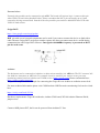
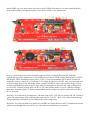
“MyGeiger” – is original DIY Geiger Counter module developed and designed in RH Electronics. The
module will allow you to build your own Geiger Counter with SBM-20 (STS-5) tube. “My Geiger” can be
purchased as DIY kit or as soldered module.
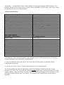
Technical specifications:
PCB compatible for Geiger Tubes
High Voltage
Measurement Period (with countdown)
Bar graph scale
Display
CPM counting ability
Radiation Dose range with SBM-20
Display range (min/max)
Conversion Factor (calibration menu)
Alert Threshold
Battery Type Confirmation (calibration menu)
CPM measurement accuracy
Event indication
Battery indication
Tube voltage measuring
Sound Buzzer On/Off control
Supply Voltage
Supply Current
PCB dimensions
PC Windows Software
Arduino
Geiger Bot
Relay Module
Ni-MH / Ni-Cd battery 4x 1.25V
Alkaline Battery 3x 1.5V
Ni-Zn Battery 3x 1.6V
Li-PO / Li-Ion battery 3.7V
TTL Module / Enclosure / Geiger Tube
Batteries and Charge Module
SBM-20 / STS-5 / J305
Auto adjusted 395V- 410V
Depend on Firmware version*
30 CPM – 800 CPM; 1 sec update
Nokia 5110 LCD, Smart backlight control
0 CPM – 500000 CPM
0.01 uSv/h – 1000 uSv/h
0.01uSv/h – 99.9 uSv/h; 0.10 mSv/h – 9.99 mSv/h
0.0001 – 0.0250 (saved to EEPROM)
120 CPM – 5000 CPM (saved for session only)
Yes (saved to EEPROM)
1% - 4% (low cpm >>> better accuracy)
LED; Buzzer
Yes, for Ni-MH and Li-PO (beta)
Yes
Yes, controlled with key
3.70V – 5.50V
10mA at background level
118 x 55 mm
Native Logger Software (required TTL module)
Compatible
Compatible (required external components)
Compatible
Compatible, 150 hours**
Compatible ***
Compatible ***
Compatible in beta***
Not included
Not included
* For firmware 1.02 measurement period is auto adjusted 30s/10s/5s. For firmware since 1.03 moving
average algorithm is used with fixed 10 seconds period.
** Time of continuous work of the device, for 4xAA batteries with capacity of 1800mAh, natural
background measurement.
*** Please refer “Power Source” chapter of the manual for more technical details.
The circuit includes auto adjusted high voltage circuit with bandgap IC that keeps the tube voltage
between 395V- 410V. The microcontroller perform precision high voltage measurement and correct high
voltage if battery voltage goes down. User do not need to calibrate high voltage, user do not need to worry
about high voltage drops because of low battery. This functions fully controlled by original software
algorithm.
Firmware 1.03 shipped since 08 Dec. 2013 has moving average algorithm for counting CPM. When
testing radioactive samples you'll need to wait up to 60 seconds to get full results. If radiation goes
dramatically up then alert system will inform you immediately with activating logic 1 level on ALR pin
and lighting up LCD backlight for visual signalization.
Firmware 1.00 - 1.02 shipped before 08 Dec. 2013 has dynamic auto adjusted counting period for CPM.
When radiation level goes up, the software will reduce period from 30 seconds to 10 or 5 seconds.
For upgrading PIC firmware please contact support with your order number.
The display has fast graphic scale that represents each second measurement. The resolution of the scale is
30-800 cpm and it updates every second.
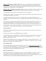
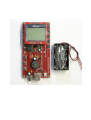
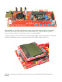
The module includes Nokia 5110 graphic LCD. All information is presented on the display: time
countdown, sound on/off indicator, battery level indicator, high voltage, radiation dose, graphic scale and
cpm value.
To reduce power consumption, the backlight will be powered off for background levels. Otherwise you
can light up the backlight for several seconds if pressing “OK” button. If cpm value will reach the
threshold ALERT value then the backlight will light up by auto to warn you about the dangerous level.
To mute sound or to turn it back, press and hold “+” (plus) button on the end of each countdown period.
Press and hold “+” button when 3 seconds left before new measurement cycle.
Calibration Menu:
The dosimeter has simple calibration menu where you can change conversion factor for your tube and
confirm battery type.
The factor value will be saved to EEPROM memory of the MCU.
To enter calibration menu press and hold “-“ (minus) button on the end of each countdown period. Press
and hold “-” button when 3 seconds left before new cycle. In calibration menu use “-“, “+” keys to
modify parameter and press “OK”.
In the end of the calibration process you’ll need to confirm if you are using Li-PO battery. Press “+” for
YES or “-“ for NO. The choice is saved to EEPROM. It’s important to confirm battery type to get right
battery capacity indication for Ni-MH and Li-PO.
Alert CPM threshold:
The alert threshold is 600 cpm by default and new value will be saved only to temporary memory until
power loss. To set alert threshold press “+” button during device start up. Use “+” or “-“ buttons to set the
value and press “OK” for saving and continue of device operating. If no buttons are pressed during device
start up then the default 600 CPM threshold will be used.
Battery Voltage Indicator:
By default battery indicator on the display allows you to control Ni-MH (Ni-Cd) capacity. Take note, if
you use other power sources, then the battery indicator will not display the true readings! In this
circumstance you can ignore battery indicator level. If using one 3.7V Li-PO please confirm in calibration
menu this battery type. It will allow displaying right battery capacity for Li-PO.
CPM counting:
The MCU can count up to 500000 CPM. It’s high enough for theoretical usage with many Geiger tubes.
The maximum radiation dose that can be displayed is 9.99 mSv/h (500000 cpm * 0.0198 factor). In real
life condition because of tube limitation and tube “dead time” you will not go close to this values.
Maximum value that can be registered with SBM-20 is about 1000 uSv/h (1.00 mSv/h). Measurement
accuracy is better on low cpm value. Maximum cpm error value is 4%.
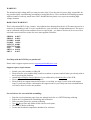
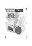
Display ranges:
0.1 uSv/h – 9.99 uSv/h
10.0 uSv/h – 99.9 uSv/h
0.10 mSv/h – 9.99 mSv/h
Typical display
Power Source:
Please read this section carefully! We are not responsible for any technical problem that caused by
user because of wrong power source or batteries connection! Li-PO batteries are contains explosive
materials! Use Li-PO only if you familiar with the safety.
The MCU requires 4.00V-5.50V, but it will continue to work down to 3.30V. According the datasheet,
only 4.00V-5.50V zone is guaranteed by Microchip. That’s why is recommended to keep VDD
voltage between 4.50V-5.50V. EEPROM write function may fault when VDD is not in recommended
range, when performing calibration please connect device to recommended power sources!
The board includes D1-D4 diodes and jumper “JMP1” for configuration different power sources. D1-D4
diodes allow connecting USB and Ni-MH batteries simultaneously, but 0.3V will drop on the diodes. You
will not need to remove batteries if going to connect the dosimeter to computer USB or TTL module. The
PCB has option to exclude the diodes when connecting the battery to Li-PO pins, please refer each battery
type description below.
1. Ni-MH 4x 1.25V
Recommended power source for the kit is USB 5V or 4x 1.25V Ni-MH batteries. You can connect
simultaneously USB and batteries! The board will use the higher voltage source. JMP1 must be
installed. Battery holder wires are soldered to Ni-MH, please refer polarity.
Minimum Ni-MH batteries capacity that can be used for the kit is 1000mAh. Recommended capacity is
2300mAh.
2. Alkaline 3x 1.5V / Ni-Zn 3x 1.6V
(Require 3xAA battery holder)
Connect these batteries to Ni-MH PCB pins, JMP1 must be installed. Take note that battery indicator on
the LCD is not applicable to these batteries type.
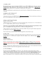
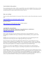
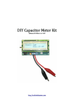
3. Battery with 5V Step-UP module
(Require external module)
Additional option for powering the kit is 5V Step-Up module usage. You can use 2x 1.5V AA batteries or
one 3.7V Lithium battery, please refer power circuit diagram.
Take note: 5V step up module consume additional current and it has about 75% performance. Total
power consumption of the Geiger kit will rise to 25mA for background levels.
Charge module for Li-Ion (if used) must be connected to CHR Li-PO pins. Step-UP module output must
be connected to Li-PO pins. JMP1 is removed!
Take note that battery indicator on the LCD is not applicable to these batteries type.
4. USB / 5V DC
If the dosimeter is used only as a monitoring station and not as portable device, you can use low current
AC/DC adapter 5V or USB from the computer. Solder DC adapter wires to CHR Li-PO pins, JMP1 is
installed.
5. 6F22 9V Battery
(Require external module)
Require external module with 5V voltage regulator. LM7805 / LM317 / AMS1117 can fit. 9V battery
cannot be connected directly to the PCB! JMP1 must be installed! 5V regulator connected to NiMH pins. Simultaneously usage of USB and 6F22 with 5V regulator is allowed.
Usually 9V batteries have small capacitance of 250-650 mAh, that’s why it’s not recommended. Take note
that battery indicator on the LCD is not applicable to these batteries type.
6. 3.7V Li-PO Battery
The kit can operate in beta-mode even from one 3.7V Li-PO battery. The benefit of using Li-PO is
smallest battery dimensions. The battery can be installed under the PCB that will significantly reduce the
enclosure volume. Minimum 800mAh capacity of battery is recommended. JMP1 is removed! Connect
3.7V battery to Li-PO pins (it exclude diodes). Charge module can be connected to CHR-LiPO pins.
Before connecting the Li-PO it’s important to calibrate conversion factor and confirm in calibration menu
you are going to use this battery type. Take note: operating at VDD lower than 4.00V is in beta mode!
That’s why is not recommend to perform any EEPROM WRITE functions when powering the kit from
3.7V Li-PO.
Power sources summary:
1.
2.
3.
4.
5.
6.
4.8V Ni-MH-----------------------------------------Recommended
USB 5V----------------------------------------------Recommended
Alkaline / Ni-Zn------------------------------------Compatible
Battery with 5V step up module------------------Compatible
6F22 9V with 5V regulator------------------------Compatible
3.7V Li-PO------------------------------------------Compatible in beta
Please consider the best way for your kit.
User is responsible to connect all external modules correctly! Check all external modules connection
is correct! Check JMP1! Do not overheat Li-PO wires with solder iron!
Radiation Logger Software:
Please download the latest version of logger software and logger user manual PDF from our website:
http://radiohobbystore.com/radiation-logger/
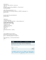
The software compatible only with Windows OS. It allows creating CSV logs file on your PC and build
graphs from previously saved logs files. Since 1.4 logger version it also support direct uploading to
http://xively.com. To connect the dosimeter to a computer you’ll need external USB-TTL module. TTL
module is not included in the purchase, but any low cost FTDI can be used. The dosimeter sends CPM
data to the computer via UART protocol each time it updates on the LCD.
Recommended TTL modules are:
1. FTDI FT232 3.3V/5V
2. CP2102
USB Serial Port Settings:
1.
2.
3.
4.
Baud Rate: 2400
8 Data Bits
Parity none
1 Stop Bit
4 pins on the PCB are intended for communication with Logger Software: RX, TX, 5V, GND. When
logging data you can power the device from 5V rail of your PC via TTL module. If batteries power supply
used please connect only 3 pins to TTL Module: RX, TX, GND.
When powering the kit in beta-mode from one 3.7V Li-PO it’s recommended to use 3.3V logic level FTDI
module.
External Alert:
External relay module can be connected to pin ALR. The board will activate logic 1 status on this pin
when CPM will reach alert threshold value. Please remember that MCU pin can supply up to 10mA
current for driving external load. Instead of the relay module you can drive additional Alert LED with
300R-1K load resistor.
Geiger BOT:
https://sites.google.com/site/geigerbot/
BOT pin with several external components can be used if you want to connect the device to Ipad with a
cable. Because Geiger BOT use beeper sound to capture the data you cannot mute device sound during
communication with Geiger BOT software. 5ms signal with 4000Hz frequency is presented on BOT
pin for each event.
Arduino:
The dosimeter can be connected to Arduino (or other microcontroller) via ARD pin. The PIC generate 2uS
low-high-low interrupts on ARD pin. For example it may be useful if you want to create your own
monitoring station based on Arduino and COSM service (https://xively.com/) Please read tutorial here:
https://xively.com/dev/tutorials/
We provide simple Arduino example for connecting the Geiger Kit via Arduino as radiation sensor feed.
For more technical information please visit COSM website. RH Electronics monitoring feed can be visited
here:
https://xively.com/feeds/122314
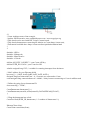
Hardware requirements: Geiger Kit with tube, Arduino UNO board, W5100 Arduino Ethernet Shield,
jumper wires.
Connect ARD pin ton INT, the kit can be powered from Arduino 5V line.
/**
* Cosm Arduino sensor client example.
* Author: RH Electronics www.radiohobbystore.com / www.mygeiger.org
* This sketch can be used with DIY Geiger Counter board.
* This sketch demonstrates connecting an Arduino to Cosm (https://cosm.com),
* Full tutorial available here: https://cosm.com/docs/quickstart/arduino.html
*
*/
#include <SPI.h>
#include <Ethernet.h>
#include <HttpClient.h>
#include <Cosm.h>
#define API_KEY "API KEY" // your Cosm API key
#define FEED_ID 123456 // your Cosm feed ID
volatile unsigned long CNT; // variable for counting interrupts from dosimeter
// MAC address for your Ethernet shield
byte mac[] = { 0xDE, 0xAD, 0xBE, 0xEF, 0xFE, 0xED };
unsigned long lastConnectionTime = 0; // last time we connected to Cosm
const unsigned long connectionInterval = 60000; // delay between connecting to Cosm in milliseconds
// Define the string for our datastream ID
char sensorId[] = "CPM";
CosmDatastream datastreams[] = {
CosmDatastream(sensorId, strlen(sensorId), DATASTREAM_FLOAT),
};
// Wrap the datastream into a feed
CosmFeed feed(FEED_ID, datastreams, 1 /* number of datastreams */);
EthernetClient client;
CosmClient cosmclient(client);
void setup() {
// put your setup code here, to run once:
CNT = 0;
attachInterrupt(0,GetEvent,RISING); // Event on pin 2
Serial.begin(9600);
while (Ethernet.begin(mac) != 1) {
Serial.println("Error getting IP address via DHCP, trying again...");
delay(15000);
}
Serial.println("Network initialized");
Serial.println();
}
void loop() {
// main program loop
if (millis() - lastConnectionTime > connectionInterval) {
// read a value from the pin
unsigned long sensorValue;
sensorValue = CNT; //CPM
// send it to Cosm
sendData(sensorValue);
sensorValue = 0;
//CNT = 0;
CNT = 0;
lastConnectionTime = millis();
}
}
void sendData(int sensorValue) {
datastreams[0].setFloat(sensorValue);
int ret = cosmclient.put(feed, API_KEY);
}
void GetEvent(){ // Get Event from Device
CNT++;
}
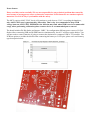
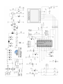
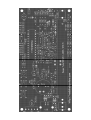
Assembling notes:
This kit requires good soldering skills and ability to read electrical circuit. Print out the circuit and
keep it in front of you during the soldering for easy reference.
Remember, do clean solder work and install right components in the right place. It is always hard to
unsolder components from the PCB. RH Electronics cannot be responsible if you'll overheat your PCB or
will damage the kit components by incorrect soldering. Double check yourself before you solder. All
components must be installed as electrical circuit show, in proper polarity and right direction. Any
hardware modifications are not acceptable for technical support.
Take your time when performing solder work. It may take about 3 hours to complete the kit.
Recommended to use 0.8mm or 1.00mm thickness lead solder wire with low melt point, such as:
60/40 – 186 Celsius (386 Fahrenheit)
63/37 – 183 Celsius (361 Fahrenheit)
Do not use lead free solder! Lead free solder require higher temperature to flow that may destroy
PCB pads! For good solder flow trim solder station temperature to 350C Celsius.
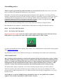
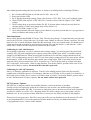
A solder joint should look like the picture above shows. It’s recommended to read general soldering guide
from Sparkfun Electronics.
If you'll need to remove excess solder from the pad, use desoldering tools (braid wick or small pump).
VERY IMPORTANT:
After soldering, the board must be washed with isopropyl alcohol and soft brush to remove all flux!
The flux remains affect high voltage converter and may cause different technical problems with the
board. You can use special industrial flux removers or buy isopropyl from hardware store. When
washing the PCB, pay attention that the flux remover will not slip into buzzer, switches or USB
connector. It may cause mechanical problems. Dry the PCB properly before first powering.
The kit has about 100pcs components. You need to identify each part before you start to solder it.
Check all resistors value with a multimeter because reading color code may be confusing. 10x 10M
resistors and 1x 100K resistor have to be 1%. Other resistors in the kit may be supplied as 1% or as 5%,
depend on stock.
Any hardware or software modifications performed by buyer are not qualified for technical
support! You are fully responsible to solder this kit correctly.
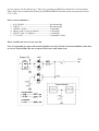
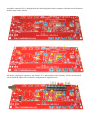
Assembly sequence flow is displayed on the following photos and in youtube video that can be found on
product page on the website.
All diodes, electrolytic capacitors, led, buzzer, IC’s and transistors have polarity. Please use electrical
circuit and PCB silkscreen to install the components in right direction.
Put the JMP1 cap to be able to power the device from USB at first start up. For more technical details
about further jumper configuration please refer “Power Source” user manual part!
Now it’s good moment to perform a middle-point test. Before continue installing PIC and other
components, power the board from 5V on Ni-MH pins and check VFER voltage inside pin#5 of 28 PIN
DIP Socket. VREF should be between 2.49V-2.54V. If you read something else it means you need to
modify R2 value or replace IC2. Check also 3.3V voltage on D9 zener after R5. And very important now
to check voltage drop on D1-D4 diodes. Some samples of BXZ55 zeners may consume larger current
because semiconductors are not ideal. Larger current consumption will lead to big supply voltage drop
over D1-D4! A normal voltage drop is 0.20V-0.30V after shottky diodes. If you see that D9 consume
more than 5mA then replace it. Please contact RH Electronics support to get free replacement for D9 or
IC2 if you need.
Revision 1.02 of kit has P1 potentiometer. The total value of P1+ R11 may be between 3K-5K. Usually it
can be 5K potentiometer (P1) with 200 ohm resistor (R11). Trim P1 + R11 to 3K value for first start up.
This potentiometer will allow you to calibrate tube start voltage later.
Revision 1.02 of kit has JMP3. Put jumper cap on JMP3 to connect buzzer to MCU. Sound can be muted
with tact key through software, but also you can connect external button if you wish.
When installing PIC into DIP socket please be careful! I have seen board where PIC was inserted by
incorrect pressure and several leads were curled under the PIC body. Take note about IC polarity!
Tweezers can be useful tool if you’ll need to remove or reinstall the PIC.
To solder the display first install long male pins into female sockets, then place the LCD over the board
and solder. The bottom 3 pins row connected to CKL, VSS, LIGHT contacts of the LCD.
LED and 3 tact buttons are soldered in the last stage. Now wash the PCB with IPA99% and dry it
properly.
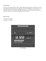
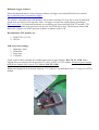
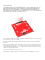
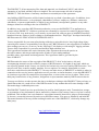
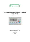
LCD troubleshooting:
Today the project running with Nokia 5110 LCD module, see pin-out from the photo below. This
graphic LCD has extremely small current consumption, but unfortunately these displays are no
longer produced by Nokia. These displays were previously installed in retired Nokia 3310 cell
phones. LCD may have some light scratches on the surface. There is no new Nokia LCD available in
the world, but we try to deliver the best samples we can get.
If you purchased non-soldered kit, please pay attention how to solder LCD pins correctly! The bottom pins
row is soldered only to CLK, VCC, LIGHT.
Most of the problems associated with the LCD are caused by poor contact between LCD and the LCD
main board.
Nokia LCD module build from 2 parts: The LCD and LCD PCB. Electrical contact between LCD itself
and red PCB provided only by pressure. 4 metal clamps may be too loose, that cause blank LCD screen
with only backlight operating. In this case open 4 clamps, clean LCD contacts and reinstall the LCD into
its PCB. Close and tight clamps carefully.
Test if you can read 3.00V-3.30V on LCD VCC pin.
If the backlight is not bright enough for your consideration, substitute R24 47R with a smaller value.
After soldering and washing the board you have to check several things before installing GM Tube.
1.
2.
3.
4.
Put 1-Position DIP Switch to ON and trim P1+R11 value to 3K
Power the kit from USB.
See if display shows high voltage. Some value between 370V-430V is ok, you’ll calibrate it later.
Check VREF value at pin#5 of PIC16F876A. Current revision of the kit support 2.50V VREF
voltage.
5. Check voltage drop on protection diodes D1 D2. If all parts where soldered correctly then kit
consume about 10-14mA and voltage drop will be about 0.3V
6. Check LCD VDD voltage is 3.30V
7. Close tube terminals with your fingers of one hand for very short periods and see if you get buzzer
clicks, led flashes and counts on the LCD.
Tube Installation:
Power off the kit and install SBM-20 Geiger Tube. The tube has polarity! To install the tube you’ll need to
remove the LCD first. Geiger tubes are very fragile items. Handle it with care! Do the visual test. The tube
must to be free of cracks and dents. Shake the tube and check is here any sounds inside. It's should not be!
Clean rust from tube terminals for good electrical contact. The tube has anode (+) and cathode (-) sides.
Anode side is marked on tube body and it connected to R18 resistor.
Calibrating for 1.02-1.04 firmware:
If everything is right then it’s time to calibrate tube starting voltage. You need to power the board with
exactly 4.80V, use small regulated power supply connected to Ni-MH pins. 4.80V is a middle capacity
voltage for Ni-MH batteries. When powering the board from 4.80V the tube voltage should start with
380V- 385V reading and go slowly to 400V. If your first voltage reading on lcd is less, then power off the
kit and turn P1 a little to left direction and recheck start voltage again. Find P1 position where your kit
start with 380V when powered from 4.80V. In similar way, if you read first start up voltage more than
385V with 4.80V then trim P1 a little to right direction. You need to find P1 position where on 4.8V kit
shows half of battery capacity. Do not trim P1 when kit is powered!
Calibrating for 1.05-1.07 firmware:
Since 1.05 firmware calibration is different. Trim P1 to the middle position. Power the kit with 4.8V
(middle point of Ni-MH capacity). Check battery indicator on LCD after 10-20 seconds. You should see a
half. If not, power off the device, remove LCD and re-trim P1 a little. You need to find P1 position where
on 4.8V kit shows half of battery capacity. Do not trim P1 when kit is powered!
MCU Firmware Updates:
PIC16F876A is shipped with the last available firmware version at the date of purchase.
Usually user do not required to update device firmware, but in some cases update maybe performed
through installing another PIC chip. If you want to jump from your to the newest version of the firmware
you may be asked to cover PIC cost + shipping charge. We do not charge you for the update, only for
hardware cost. In case you have trouble with newer version you can always roll back to old program.
This project is not open source. Hex file or any source files are not distributed over the internet. Hex file
or pre-programmed PIC is not sold separately from the hardware. Please see additional details in
“Copyright and License” section of this manual.
General advices:
Avoid long wires connection inside and outside the enclosure. Avoid loose contacts for power source or
batteries. Never just wrap wires around the connection pins! Use proper 2.54 female connectors or solder
tinned wires directly to the PCB pins. Check the polarity and direction of all connections you make!
Do not touch tube with your hands when device is powered. Do not place Geiger module on any metal
surface. Plastic case recommended for the counter. Do not short tube terminals. Do not try to measure
high voltage tube clips with a multimeter!
Troubleshooting:
Most of the problems with kit caused by incorrect soldering or short circuits between components. Please
recheck your soldering. Because high voltage is presented it’s very important to wash the PCB, any small
flux remains usually affect high voltage output.
High voltage problems:
1. Wash the PCB and check T1, D6, D7, D8 polarity.
2. Check voltage multiplier soldering is correct on all points! Exceed solder may cause shorts and
create additional connections between components.
3. Check VREF voltage is correct, pin#5 of PIC will read as 2.50V
4. Check PWM signal from pin#13 of PIC is delivered to T1 base.
5. Check if L2 coil has DC resistance about 15-30 ohm.
6. Check 100M divider is soldered correctly.
7. Check R7 value is 100K.
8. Check JMP1 configuration is correct. When using Li-PO please connect battery to lipo connectors,
otherwise protection diodes will cause high voltage to drop to 250V-300V.
LCD is blank:
1. Please refer LCD troubleshooting above. Usually the problem caused by poor contacts inside LCD
pcb.
2. Check if DIP switch placed to ON position.
High current consumption:
1. May be caused by D9 zener malfunction. Remove PIC and LCD to check zener current. Current
consumption without PIC and LCD should be about 5mA!
WARNING!
The board has high voltage 400V presented on tube clips! If you buy the kit you are fully responsible for
any possible injury caused during assembling or using this device. Never touch the PCB during operation
with two hands or with any metal items. Place finished kit into plastic case to prevent touching high
voltage elements.
RADIATION WARNING!
This is educational DIY Geiger Counter. Any radiation dose displayed on the kit LCD cannot be used as a
reason to do something or not. You are responsible for your own safety in high radiation area! The device
can be calibrated with precision radiation source in special lab – you make a decision if do it or not. Here
is default conversion factor values for some most popular GM tubes:
SBM-20 0.0057
SBM-19 0.0021
SI-29BG 0.0082
SI-180G 0.0031
LND-712 0.0081
LND-7317 0.0024
J305 0.0081
SBT11-A 0.0031
SBT-9
0.0117
Need help with the DIY Kit you purchased?
Please send a support request to us at: [email protected]
Support request requirements:
•
•
•
•
•
Include your order number or eBay ID
Please describe your problem fully; attach screenshots or pictures and tell what you already tried to
do for resolving the problem.
Attach high resolution focused photos of your soldered kit, from both sides of the PCB.
Please wait up to 24 hours for the response.
Please follow our support instruction because we can help you only if you'll work with support
team. If you'll not provide a information for support team or you’ll drop out from communication
we'll not be able to resolve the problem.
Several advices for successful kit assembling:
•
•
•
•
•
•
Print the circuit schematic page from user manual and refer to it OFTEN during soldering.
Follow the User Manual for assembling and calibration.
Take your time! Please do accurate soldering.
Use only Rosin Flux and Solder 60/40 with low melt point.
Clean the PCB after soldering.
Locate and download components datasheets for reference.
Your feedback for eBay purchase.
If you purchased our kit on eBay, we'll be very grateful for your positive feedback. Please leave us 5 star
score positive feedback if you are satisfied with our product and service. If there was any problem with
your purchase please contact us and we'll do our best to resolve it.
Share your worklog!
You are invited to share the photos of your project. Please send it to us and we'll post the photos on special
page.
http://radiohobbystore.com/customers-gallery-diy-kits/
Discount Coupons:
Make a short review and get discount coupon for further purchase!
http://radiohobbystore.com/discount-coupon
COPYRIGHTS AND LICENSE:
EULA license for “MyGeiger” DIY Geiger Counter Kit firmware and hardware.
Copyright© Alex Boguslavsky, RH Electronics ISRAEL
http://radiohobbystore.com
Please read the following terms and conditions carefully before using this PRODUCT. Your use,
downloading or installation of this copy of "MyGeiger" firmware indicates your acceptance of this
License.
PRODUCT here means firmware, hex or source files, hardware unit, all accompanying files, data
and materials received with your order of "MyGeiger DIY Geiger counter Kit".
If you do not agree to any of the terms of this License, then do not use, do not install, do not copy
firmware and do not distribute any of PRODUCT files. If you have purchased a single copy from RH
Electronics or an authorized distributor, reseller or any retail channel, you may return it unused, within
thirty (30) days after purchase, for a refund of your payment less any incidental charges.
Warrantee covers defects in the PRODUCT, which prevents described in user manual functions.
Warrantee does not cover fitness of purpose, not meeting of expectations or needs in the mind of the
buyer.
This PRODUCT is for personal use only and the PRODUCT’s firmware may be installed and used by on
only one “MyGeiger” Geiger Counter hardware unit. Its component parts may not be separated for use on
more than one hardware unit. All components accompanying the PRODUCT are copyrighted by RH
Electronics and may not be taken apart, modified, de-compiled, used or published with other software or
means except with the PRODUCT and may not be distributed or copied in any manner.
This PRODUCT, all accompanying files, data and materials, are distributed "AS IS" and with no
warranties of any kind, whether express or implied. The user must assume all risk of using the
PRODUCT. This disclaimer of warranty constitutes an essential part of the agreement.
Any liability of RH Electronics will be limited exclusively to refund of purchase price. In addition, in no
event shall RH Electronics, or its principals, shareholders, officers, employees, affiliates, contractors,
subsidiaries, or parent organizations, be liable for any incidental, consequential, punitive or any other
damages whatsoever relating to the use of PRODUCT.
In addition, in no event does RH Electronics authorize you to use this PRODUCT in applications or
systems where PRODUCT 's failure to perform can reasonably be expected to result in a physical injury,
or in loss of life. Any such use by you is entirely at your own risk, and you agree to hold RH Electronics
harmless from any claims or losses relating to such unauthorized use. “MyGeiger” developed and sold by
RH Electronics for EDUCATIONAL PURPOSES ONLY.
You are responsible for your own safety during soldering or using this device! Any high voltage injury
caused by this counter is responsibility or the buyer only. RH Electronics is not responsible for radiation
dose readings you can see, or not see, on the “MyGeiger” lcd display or with using PC logging software.
You are fully responsible for you safety and health in high radiation area.
This Agreement constitutes the entire statement of the Agreement between the parties on
the subject matter, and merges and supersedes all other or prior understandings,
purchase orders, agreements and arrangements. This Agreement shall be governed by the
laws of ISRAEL.
RH Electronics the owner of the copyright of this PRODUCT, all of its derivatives, title and
accompanying materials are the exclusive property of RH Electronics. All rights of any kind, which are
not expressly granted in this License, are entirely and exclusively reserved to and by RH Electronics. You
may not rent, lease, transfer, modify, translate, reverse engineer, de-compile, disassemble or create
derivative works based on this PRODUCT. You may not make access to PRODUCT available to others in
connection with a service bureau, application service provider, or similar business, or use this PRODUCT
in a business to provide file compression, decompression, or conversion services to others. There are no
third party beneficiaries of any promises, obligations or representations made by RH Electronics herein.
You may not disclose to other persons the data or techniques relating to this PRODUCT that you know or
should know that it is a trade secret of the RH Electronics in any manner that will cause damage to RH
Electronics htpp://radiohobbystore.com.
This PRODUCT and all services provided may be used for lawful purposes only. Transmission, storage,
or presentation of any information, data or material in violation of any country, state or city law is strictly
prohibited. This includes, but is not limited to: copyrighted material, material we judge to be threatening
or obscene, or material protected by trade secret and other statute. You agree to indemnify and hold RH
Electronics harmless from any claims resulting from the use of this PRODUCT, which may damage any
other party.
http://radiohobbystore.com
RH Electronics© 2013