1
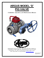
ARGUS MODEL ‘D’
PIG VALVE
Installation, Operation, and Maintenance Manual
Dedicated to Improving Your Operations for Over 50 Years
Argus Machine Co. Ltd. • 5820 - 97 Street, Edmonton, Alberta, Canada T6E 3J1
Phone: (780) 434-9451 • Fax: (780) 434-9909 • www.argusmachine.com
MN-PV-004, September 2008
Printed in Canada, ©2008
Argus Machine Co. Ltd.
TABLE OF CONTENTS
1.0
SCOPE ------------------------------------------------------------------------------------------------------------------------------------ 2
2.0
GENERAL -------------------------------------------------------------------------------------------------------------------------------- 2
3.0
APPLICABLE STANDARDS -------------------------------------------------------------------------------------------------------- 2
4.0
SAFETY ----------------------------------------------------------------------------------------------------------------------------------- 2
5.0
HANDLING AND STORAGE -------------------------------------------------------------------------------------------------------- 3
5.1
5.2
6.0
HANDLING ---------------------------------------------------------------------------------------------------------------------------- 3
STORAGE----------------------------------------------------------------------------------------------------------------------------- 3
INSTALLATION------------------------------------------------------------------------------------------------------------------------- 3
6.1
6.2
6.3
7.0
INLET AND OUTLET PIPING----------------------------------------------------------------------------------------------------- 3
ORIENTATION ----------------------------------------------------------------------------------------------------------------------- 3
MOUNTING --------------------------------------------------------------------------------------------------------------------------- 4
OPERATION ----------------------------------------------------------------------------------------------------------------------------- 5
7.1
7.2
PIG SENDING ------------------------------------------------------------------------------------------------------------------------ 6
PIG RECEIVING --------------------------------------------------------------------------------------------------------------------- 8
8.0
MAINTENANCE------------------------------------------------------------------------------------------------------------------------- 9
9.0
INJECTION GUIDELINES---------------------------------------------------------------------------------------------------------- 10
9.1
9.2
9.3
9.4
9.5
9.6
INTRODUCTION -----------------------------------------------------------------------------------------------------------------GENERAL --------------------------------------------------------------------------------------------------------------------------INJECTION EQUIPMENT ------------------------------------------------------------------------------------------------------CLEANERS ------------------------------------------------------------------------------------------------------------------------LUBRICANTS ---------------------------------------------------------------------------------------------------------------------SEALANTS--------------------------------------------------------------------------------------------------------------------------
10
10
10
10
10
10
10.0
TROUBLESHOOTING -------------------------------------------------------------------------------------------------------------- 11
11.0
HOW TO ORDER PIG VALVES & PIG VALVE SERVICE ---------------------------------------------------------------- 12
11.1
11.2
11.3
ORDERING ARGUS PIG VALVES -------------------------------------------------------------------------------------------- 12
ORDERING SERVICE FOR ARGUS PIG VALVES ----------------------------------------------------------------------- 12
CONTACT INFORMATION ----------------------------------------------------------------------------------------------------- 12
Figure 1:
Figure 2:
Figure 3:
Figure 4:
Figure 5:
Pig Valve Orientation ------------------------------------------------------------------------------------------------------------ 4
Argus Pig Valve Model “D” c/w Pressure Alert Valve, Integral Equalization Valve ------------------------- 5
Argus Integral Equalization Valve ------------------------------------------------------------------------------------------- 6
Argus Model ‘D’ Entry Cap & Lug Wrench-------------------------------------------------------------------------------- 7
Top View of Argus Model ‘D’ Pig Valve c/w Gear Operator --------------------------------------------------------- 8
PIG VALVE (MODEL ‘D’)
INSTALLATION, OPERATION, AND MAINTENANCE
MN-PV-004
September 2008
Page 1
1.0 SCOPE
Argus Machine Co. Ltd. (Argus) manufactures Pig Ball Valves (Pig Valves) with flanged pipeline connections. This
manual covers the installation, operation, and maintenance of Argus Pig Valves (model ‘D’).
2.0 GENERAL
Installation, operation, and maintenance of Pig Valves, model ‘D’, shall comply with the procedures as described in
this manual.
The Pig Valve is a double block and bleed valve which allows pigs to be inserted and removed, providing a safe and
convenient alternative to the traditional method of pigging operations (with valves, tees, and traps). This is made
possible by having independent upstream and downstream seats which isolate the body cavity from the upstream and
downstream pressures when the valve is “CLOSED”. An entry cap located at the top of the Pig Valve main body
allows pigs to be inserted into and removed from the flow line when the valve is in the closed position. The standard
Argus Pig Valve is designed for:
1)
Operating temperature range of -50ºF (-46ºC) to +250ºF (+121ºC).
2)
Sweet and sour service.
3)
Sending and receiving “Bullet”, “Scraper”, and “Spherical” type pigs.
3.0 APPLICABLE STANDARDS
The Pig Valve has been designed to meet the requirements of the following applicable standards:
1)
API 6D/ISO 14313†
2)
API 598
3)
NACE MR0175
4)
ASME B16.5, B16.34, B31.3, & Section VIII
5)
MSS SP-25
†
Face to face dimensions for the model ‘D’ exceed API 6D specifications (see “TB-PV-030” for details).
4.0 SAFETY
Many routine procedures are potentially hazardous if executed incorrectly or in unsafe conditions, particularly when
toxic/flammable product is present. Caution must also be exercised when high temperature and/or pressure exist in
the system. The routine of sending a pig and receiving a pig, while not complex, requires prudence to prevent
personal injury and/or damage to the equipment. The procedures detailed in this manual must be followed closely.
Other precautions that MUST be observed are listed below:
1)
Pig Valves MUST be suitable for the service conditions.
2)
Always follow government and site safety regulations.
3)
Use appropriate safety equipment and clothing, including eye protection, when operating the Pig Valve.
4)
Stand clear when bleeding down the main body cavity and removing the entry cap, to prevent exposure to
spray, splatter, or spillage of any hazardous media which may be contained inside the valve.
5)
Always use Argus O.E.M. parts for service and repair.
6)
Never strike the Pig Valve or attached equipment.
7)
All accessories attached to the Pig Valve MUST be suitable for the service conditions.
8)
Never install or remove accessories from a Pig Valve that is under pressure.
9)
At least one bleed valve MUST be installed in the Pig Valve before installation or operation.
PIG VALVE (MODEL ‘D’)
INSTALLATION, OPERATION, AND MAINTENANCE
MN-PV-004
September 2008
Page 2
5.0 HANDLING AND STORAGE
5.1
HANDLING
1)
Do not lift the Pig Valve by any part of the gear operator, entry cap or any other accessories attached to the Pig
Valve. Use the attached Lifting Lugs whenever possible.
Care should be taken to ensure that the Pig Valves are never subjected to impact or dropped during
installation, storage, or handling.
2)
5.2
STORAGE
1)
Pig Valves should be stored in a clean dry environment and should be left on shipping pallets or in original
packaging prior to installation.
All flange protectors should remain in place until installation of Pig Valve.
Pig Valves should be stored in the “FULLY OPEN” position (prevents damage to ball and seats).
2)
3)
6.0 INSTALLATION
6.1
INLET AND OUTLET PIPING
1)
Ensure the Pig Valve connections match (see nameplate on Pig Valve) the nominal size and pressure rating of
the inlet and outlet piping connections (e.g. 10” 600 ANSI Class RF flanged connection).
It is the responsibility of the piping designer to address vibration, thermal effects, line stresses, supports or any
other factors that may occur due to field conditions. They shall also determine if a by-pass line is necessary to
prevent pressure build-up of flow line during the pigging operation.
The inlet and outlet piping connections shall be aligned in such a manner to eliminate any additional stresses
due to Pig Valve installation.
2)
3)
6.2
ORIENTATION
(Refer to Figure 1)
1)
It is RECOMMENDED to install Argus Pig Valves with the entry cap facing upward to avoid spillage of media
during the insertion and removal of pigs. Argus’ standard Pig Valves MUST be installed with the entry cap
facing upward with the flow being horizontal. Optional entry cap assemblies are available for vertical
installation or where it is necessary to install the Pig Valve with the entry cap on its side.
Pig Valves equipped with the Argus “Multi-Pig Launcher” (see “TB-ML-002” technical bulletin), MUST be
installed with the “Multi-Pig Launcher” facing upward.
Flow direction is indicated on the Pig Valve nameplate beside “FLOW”. When marked L←R flow is from the
right side to the left side of Pig Valve. When marked L→R flow is from the left side to the right side of Pig valve.
2)
3)
NOTE:
Pig Valve “sender type” (Sender) if equipped with an optional tailpiece stopper MUST be installed
with the tailpiece stopper in the upstream tailpiece. Pig Valve “receiver type” (Receiver) MUST
have the tailpiece stopper installed in the downstream tailpiece. Consult factory for non-standard
pig stoppers.
PIG VALVE (MODEL ‘D’)
INSTALLATION, OPERATION, AND MAINTENANCE
MN-PV-004
September 2008
Page 3
Sender: Orientation 1:
Flow Direction: From Left to Right
Receiver: Orientation 1:
Flow Direction: From Left to Right
PIG
PIG
Tailpiece Stopper
Upstream Position
(Optional)
Tailpiece Stopper
Downstream Position
(Required)
You Are Here
You Are Here
Sender: Orientation 2:
Flow Direction: From Right to Left
Receiver: Orientation 2:
Flow Direction: From Right to Left
PIG
PIG
Tailpiece Stopper
Downstream Position
(Required)
Tailpiece Stopper
Upstream Position
(Optional)
You Are Here
You Are Here
Figure 1: Pig Valve Orientation
6.3
MOUNTING
1)
Prior to installation and once the flange protectors have been removed the Pig Valve should be inspected inside
for foreign materials and outside for signs of tampering or damage.
All sealing surfaces MUST be visually inspected to ensure they are free of foreign material or damage.
Allow sufficient workspace around the Pig Valve for accessibility to allow for proper servicing and/or removal.
Pig Valve MUST be installed in the “FULLY OPEN” position.
Ensure that at least one of the accessory ports in the Pig Valve has been equipped with a bleed valve (see
Figure 2 & Table 1).
All flange studs and nuts must be tightened as recommended by industry standards.
2)
3)
4)
5)
6)
PIG VALVE (MODEL ‘D’)
INSTALLATION, OPERATION, AND MAINTENANCE
MN-PV-004
September 2008
Page 4
Figure 2: Argus Pig Valve Model “D” c/w Pressure Alert Valve, Integral Equalization Valve
Nominal Valve Size
NPS
6” / 8”
10” / 12”
DN
150 / 200
250 / 300
Thread / Pipe Size
(NPT)
3/4”
1”
Table 1: Standard Accessory Port Size for Model ‘D’ Pig Valves
7.0 OPERATION
(Refer to Figures 1 thru 5)
In the following section on Argus Pig Valve Operation, it is assumed that the orientation of the Pig Valve is such that
the rotating stem / gear operator is facing the field technician and the flow is “left to right” for pig sending and
receiving.
CAUTION:
1) Do NOT leave Pig Valve in a partially open position as this may damage the seats.
2) Before closing Pig Valve, the pipeline must be cleaned to purge all foreign materials, which
may cause damage to the ball and/or ball seats (typical for new or repaired pipelines).
3) Pigs must not exceed Argus maximum recommended dimensions (see “TB-PV-031”
technical bulletin).
4) Steel brush style pigs are NOT recommended. The wires may scratch the seat and/or ball
sealing surfaces or come loose and wedge between the seat and ball.
5) Use the supplied Argus Pig Valve Entry Cap lug wrench to open and close the entry cap.
Other types of wrenches may damage the cap.
PIG VALVE (MODEL ‘D’)
INSTALLATION, OPERATION, AND MAINTENANCE
MN-PV-004
September 2008
Page 5
WARNING:
7.1
1)
2)
3)
4)
Do NOT use a metal-faced hammer to loosen entry cap. Hammering can crack the entry
cap. Failure to follow these instructions may result in serious injury or fatality.
PIG SENDING
Open by-pass valve (if present).
Close Pig Valve (clockwise when flow is L→R and counterclockwise when flow is L←R). The “indicator” on the
gear operator hub MUST read “CLOSED”.
Slowly open bleed valve, bleeding pressure and draining fluid from Pig Valve main body cavity.
Ensure safety release pin is installed in the integral equalization valve (see Figure 3), preventing accidental
operation during the pigging operation.
Figure 3: Argus Integral Equalization Valve
5)
Unscrew Pressure Alert Valve (PAV) stem, which is attached to the entry cap with the safety chain. Do NOT
inadvertently loosen the Pressure Alert Valve (PAV) body from the entry cap adapter.
WARNING:
Do NOT remove Pressure Alert Valve stem if there is pressure present while unthreading.
Failure to follow these instructions may result in serious injury or fatality.
NOTE: The pressure alert valve MUST NOT be used to bleed down cavity pressure.
6)
Once the stem is removed from the PAV body place it and the chain on top of entry cap to ensure it will not
catch on anything while unscrewing the entry cap.
WARNING:
7)
Do not cut, or break chain off from entry cap because it will render this safety device
useless. Failure to follow these instructions may result in serious injury or fatality.
Slowly loosen entry cap by rotating counterclockwise using the supplied entry cap lug wrench (see Figure 4).
Observe the Pressure Warning Groove area at the bottom of the threads on entry cap (see Figure 4). If there is
any media flowing from this area when the entry cap is loosened, immediately re-tighten entry cap. Slowly
open bleed valve to bleed remaining pressure and drain fluid from Pig Valve main body cavity. If unable to
bleed all pressure from body cavity refer to the “Troubleshooting” section in this manual.
WARNING:
Do NOT use a metal-faced hammer to loosen entry cap. Hammering can crack the entry
cap. Care must be taken while using the entry cap lug wrench as to not strike the
Pressure Alert Valve that protrudes from the entry cap adapter. Do NOT loosen entry cap
more than one-half turn until certain there is NO leakage from the vent area. Failure to
follow these instructions may result in serious injury or fatality.
PIG VALVE (MODEL ‘D’)
INSTALLATION, OPERATION, AND MAINTENANCE
MN-PV-004
September 2008
Page 6
Figure 4: Argus Model ‘D’ Entry Cap & Lug Wrench
8)
9)
10)
11)
Unscrew entry cap, so that it clears the threads, and swing the cap 180° exposing the pig entry bore.
WARNING:
Objects such as pigs or ice slugs can get trapped and/or ejected suddenly from the valve.
Ensure that the entry cap is operated from the side of the cap, in front of the valve.
Minimize direct exposure to the valve while the cap is open. Failure to follow these
instructions may result in serious injury or fatality.
CAUTION:
It is important to prevent any foreign material from entering the Pig Valve main body cavity when
entry cap is removed. Ensure the entry cap stays clean and free of damage when removed from
Pig Valve.
Insert pig into Pig Valve. Bullet type pigs MUST be inserted nose down.
Before installing the entry cap, check that the sealing face and threads on the entry cap adapter are free of
foreign material and burrs. Make sure the o-ring is not damaged (replace as required).
Install entry cap.
CAUTION:
12)
Install PAV stem by threading clockwise into body of the PAV.
CAUTION:
13)
14)
15)
16)
Do NOT over-tighten the entry cap as excessive tightening can cause damage to the entry cap
and/or the adapter.
The PAV valve is designed to be hand tightened; do NOT over-tighten the PAV valve stem as
excessive tightening can cause damage to the PAV valve.
Close all bleed valves.
Equalize cavity pressure with the integral equalization valve (see Figure 3). Remove safety release pin and
depress operating lever to energize cavity. Release the operating lever once the valve cavity has been
energized and replace the safety release pin, locking out accidental operation.
Open Pig Valve to send pig into the flow line. (counterclockwise when flow is L→R and clockwise when flow is
L←R). The “indicator” on the gear operator hub MUST read “OPEN”.
Close by-pass valve (if present).
NOTE:
When equipped with a by-pass line, the by-pass shut-off valve may need to be closed prior to
opening the Pig Valve and sending the pig. This will help build up sufficient pressure upstream of
the pig to push it into the downstream piping. The extent of line contamination and the
interference fit between the pig and flow line will determine whether this is necessary.
PIG VALVE (MODEL ‘D’)
INSTALLATION, OPERATION, AND MAINTENANCE
MN-PV-004
September 2008
Page 7
Figure 5: Top View of Argus Model ‘D’ Pig Valve c/w Gear Operator
7.2
PIG RECEIVING
1)
2)
Once the pig has reached the Pig Valve, open by-pass valve (if present).
Close Pig Valve (clockwise when flow is L→R and counterclockwise when flow is L←R). The “indicator” on the
gear operator hub MUST read “CLOSED”.
Slowly open bleed valve, bleeding pressure and draining fluid from Pig Valve main body cavity.
Ensure safety release pin is installed in the integral equalization valve (see Figure 3), preventing accidental
operation during the pigging operation.
Unscrew Pressure Alert Valve (PAV) stem, which is attached to the entry cap with the safety chain. Do NOT
inadvertently loosen the Pressure Alert Valve (PAV) body from the entry cap adapter.
3)
4)
5)
WARNING:
Do NOT remove Pressure Alert Valve stem if there is pressure present while unthreading.
Failure to follow these instructions may result in serious injury or fatality.
NOTE: The pressure alert valve MUST NOT be used to bleed down cavity pressure.
6)
Once the stem is removed from the PAV body place it and the chain on top of entry cap to ensure it will not
catch on anything while unscrewing the entry cap.
WARNING:
7)
Do not cut, or break chain off from entry cap because it will render this safety device
useless. Failure to follow these instructions may result in serious injury or fatality.
Slowly loosen entry cap by rotating counterclockwise using the supplied entry cap lug wrench (see Figure 4).
Observe the Pressure Warning Groove area at the bottom of the threads on entry cap (see Figure 4). If there is
any media flowing from this area when the entry cap is loosened, immediately re-tighten entry cap. Slowly
open bleed valve to bleed remaining pressure and drain fluid from Pig Valve main body cavity. If unable to
bleed all pressure from body cavity refer to the “Troubleshooting” section in this manual.
PIG VALVE (MODEL ‘D’)
INSTALLATION, OPERATION, AND MAINTENANCE
MN-PV-004
September 2008
Page 8
WARNING:
8)
9)
Unscrew entry cap, so that it clears the threads, and swing the cap 180° exposing the pig entry bore.
WARNING:
Objects such as pigs or ice slugs can get trapped and/or ejected suddenly from the valve.
Ensure that the entry cap is operated from the side of the cap, in front of the valve.
Minimize direct exposure to the valve while the cap is open. Failure to follow these
instructions may result in serious injury or fatality.
CAUTION:
It is important to prevent any foreign material from entering the Pig Valve main body cavity when
entry cap is removed. Ensure the entry cap stays clean and free of damage when removed from
Pig Valve.
Remove pig from Pig Valve.
CAUTION:
10)
11)
Should the pig be difficult to remove, do NOT use excessive side force. This may result in
damage to the pig or ball. Pull the pig directly out of the Pig Valve without working it from
side to side.
Before installing entry cap, check that the sealing face and threads on the entry cap adapter are free of foreign
material and burrs. Make sure the o-ring is not damaged (replace as required).
Install entry cap.
CAUTION:
12)
Do NOT use a metal-faced hammer to loosen entry cap. Hammering can crack the entry
cap. Care must be taken while using the entry cap lug wrench as to not strike the
Pressure Alert Valve that protrudes from the entry cap adapter. Do NOT loosen entry cap
more than one-half turn until certain there is NO leakage from the vent area. Failure to
follow these instructions may result in serious injury or fatality.
Do NOT over-tighten the entry cap as excessive tightening can cause damage to the entry cap
and/or the adapter.
Install PAV stem by threading clockwise into body of the PAV.
CAUTION:
The PAV valve is designed to be hand tightened; do NOT over-tighten the PAV valve stem as
excessive tightening can cause damage to the PAV valve.
13)
14)
Close all bleed valves.
Equalize cavity pressure with the integral equalization valve (see Figure 3). Remove safety release pin and
depress operating lever to energize cavity. Release the operating lever once the valve cavity has been
energized and replace the safety release pin, locking out accidental operation.
15) Open Pig Valve. (counterclockwise when flow is L→R and clockwise when flow is L←R). The “indicator” on the
gear operator hub MUST read “OPEN”.
16) Close by-pass valve (if present).
8.0 MAINTENANCE
1)
In climates where the flow line experiences freezing temperatures, drain any water or other media (which may
solidify) from the Pig Valve thru the accessory ports on the bottom of the main body.
CAUTION:
2)
3)
Media left in Pig Valve that is susceptible to freezing may damage the Pig Valve.
It is recommended to grease Pig Valve before each pigging operation (see “Injection Guidelines”).
It is recommended to inspect entry cap seal and sealing surface during the regular pigging operation (when
entry cap is removed). Replace seal and repair seal surface as required (see “Service Manual”).
PIG VALVE (MODEL ‘D’)
INSTALLATION, OPERATION, AND MAINTENANCE
MN-PV-004
September 2008
Page 9
4)
5)
In instances where the pig valve is not used regularly, it is recommended that the pig valve be cycled ever 2-3
months.
In severe service, where media build up may be a concern, it is recommended to inject cleaners as required
(see “Injection Guidelines”).
9.0 INJECTION GUIDELINES
(Refer to Figure 2 & 5)
9.1
INTRODUCTION
1)
Argus model “D” Pig Valves are equipped with seat injection ports and a stem injection port. These ports are
used to inject cleaners, lubricants and sealants into the interface between the seat insert and the ball. Periodic
injection of these cleaners, lubricants and sealants will reduce downtime, costly repairs and prolong the life of
the Pig Valve. Cleaners and lubricants are especially recommended for severe service applications.
9.2
GENERAL
1)
2)
Refer to manufacturers’ instructions for use of injection equipment, cleaners, lubricants, and sealants.
Best results are achieved by injecting cleaners and/or lubricants while Pig Valve is in the “FULLY OPEN” or
“CLOSED” position.
Inject a sufficient quantity of cleaner, lubricant or sealant as required. A rule of thumb is to inject approximately
1-2 ounces per inch of valve size into each of the seat injection fittings.
3)
9.3
INJECTION EQUIPMENT
WARNING:
Read and follow all manufacturers’ instructions for safe operation of injection equipment.
Failure to follow these instructions may result in serious injury or fatality.
1)
2)
Injection equipment is required to inject cleaners, lubricants and sealants into the Pig Valve.
Recommend Sealweld® SuperGun or equivalent.
9.4
CLEANERS
1)
2)
Cleaners are used to clean critical seal surfaces and sealant passages by softening, flushing and removing old
sealants, residual buildup and foreign particles (such as sand, debris, scales, etc).
Recommend Sealweld® Valve Cleaner Plus or equivalent.
9.5
LUBRICANTS
1)
2)
Lubricants are designed to protect critical seal surfaces against corrosion and flush out pipeline contaminants,
as well as reduce operating torque requirements.
Recommend Sealweld® Equa-Lube Eighty lubricant, Chemola Desco 622 lubricant/sealant, or equivalent.
9.6
SEALANTS
WARNING:
1)
2)
3)
Pigging the flow line is NOT recommended after sealant has been injected into Pig Valve
(repair the Pig Valve before continuing pigging operation). Sealant may be used to ensure
positive shut-off of the flow line when the Pig Valve is closed. Failure to follow these
instructions may result in serious injury or fatality.
Sealants are designed specifically for use with minor to severe leaking valves and emergency valve sealing
operations.
Recommend (minor leakage): Sealweld® Total-Lube #911 lubricant/sealant or equivalent.
Recommend (severe leakage): Sealweld® Ball Valve Sealant #5050 sealant or equivalent.
PIG VALVE (MODEL ‘D’)
INSTALLATION, OPERATION, AND MAINTENANCE
MN-PV-004
September 2008
Page 10
10.0
TROUBLESHOOTING
Problem
Pig Valve won’t open.
Possible Causes
a) High torque.
b) Media build up causing a sticking
effect on moving parts.
c) Media inside Pig Valve is frozen.
Pig Valve won’t close.
a) Foreign matter caught in ball
and/or ball seats.
b) Stops not set properly on gear
operator.
a) Foreign matter caught in ball
and/or ball seats.
b) Ball seats scratched.
Pig Valve cavity will not
bleed down when in
“CLOSED” position.
c) Equalization valve leaks.
d) Stops not set properly on gear
operator.
e) Bleed Valve plugged.
Leakage around entry cap.
a) O-ring seal damaged.
b) Seal surface damaged.
c) Foreign matter on seal surface.
Leakage around tailpiece.
a) Primary seal in tailpiece is
damaged.
b) Seal surfaces damaged.
Bleed valve leaking.
a) Seats and/or seals damaged.
b) Bleed valve not closed.
Possible Solutions
a) Open pressure equalization valve. Check
equalization valve for blockage and repair
as required (see “Service Manual”).
b) Inject valve cleaner and lubricant into ball
seats (see “Injection Guidelines”).
c) De-ice.
a) Remove Pig Valve from flow line and
repair (see “Service Manual”).
b) Adjust stops on gear operator (see gear
operator “Operating Manual”).
a) Inject cleaner and lubricant into ball seats
(see “Injection Guidelines).
b) Remove Pig Valve from flow line and
repair (see “Service Manual”).
c) Remove Pig Valve from flow line and
repair (see “Service Manual”).
d) Adjust stops on gear operator (see gear
operator “Operating Manual”).
e) Isolate valve, bleed down the line and
replace bleed valve.
a) Remove entry cap and replace o-ring
seal.
b) Remove entry cap, inspect seal surfaces,
and repair as required (see “Service
Manual”).
c) Remove entry cap and clean off foreign
matter.
a) Remove Pig Valve from flow line and
replace primary seal (see “Service
Manual”).
b) Remove Pig Valve from flow line, inspect
seal surfaces, and repair as required (see
“Service Manual”).
a) Isolate valve, bleed down the line and
replace bleed valve.
b) Close bleed valve.
PIG VALVE (MODEL ‘D’)
INSTALLATION, OPERATION, AND MAINTENANCE
MN-PV-004
September 2008
Page 11
11.0 HOW TO ORDER PIG VALVES & PIG VALVE SERVICE
11.1 ORDERING ARGUS PIG VALVES
When Argus Pig Valves are ordered, the following information will be required:
1)
Model
2)
Size
3)
ANSI Class pressure rating and flange type (e.g. 600 ANSI Class RF)
4)
Pig Sender or Pig Receiver
5)
Flow direction (from “left to right” or “right to left”, with “rotating stem” facing user)
6)
Type of pig (Sphere or Bullet/Scraper)
7)
Quantity of pigs required
8)
Quantity of Pig Valves required
9)
Tailpiece pig stopper (optional on “Senders”)
10) Automatic or manual multi-pigging (optional, see “Multi-Pig Launcher” bulletin)
11) Options or accessories
11.2 ORDERING SERVICE FOR ARGUS PIG VALVES
When requesting service for Argus Pig Valves, please provide the following data to the Service Department:
1)
Size
2)
Model
3)
ANSI Class pressure rating
4)
Serial Number
5)
Reason for Repair
Example:
8” Pig Valve
Model “D”
600 ANSI Class
S/N PV 01000
11.3 CONTACT INFORMATION
For Ordering Argus Pig Valves or Argus Pig Valve service:
Argus Machine Co. Ltd.
Order Desk (Assembly Division)
5720-97 Street,
Edmonton, Alberta, Canada
T6E 3J1
Toll Free:
Phone:
Fax:
1-888-434-9451
780-434-9451
780-434-9909
PIG VALVE (MODEL ‘D’)
INSTALLATION, OPERATION, AND MAINTENANCE
MN-PV-004
September 2008
Page 12