1
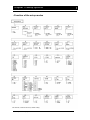
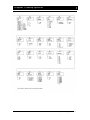
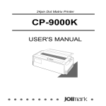
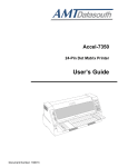
24-pin Dot-matrix Printer
FP-8800K
USER’S MANUAL
JOLIMARK®
FP-8800K
1
2
3
4
No part of this manual may be reproduced in any form.
This manual is subject to change without notice.
This manual was prepared with the greatest care. If you should find any
unclear points, mistakes, or omissions, please contact us.
We will not bear any responsibility for unsatisfactory results from the use of
this printer despite item 3 above.
* EPSON is a registered trademark of Seiko Epson Corporation.
* LQ-2550 is a registered trademark of Seiko Epson Corporation.
* IBM is a registered trademark of International Business Machines Corporation.
* IBM 2391 is a registered trademark of International Business Machines
Corporation.
* Windows is a registered trademark of Microsoft Corporation.
FP-8800K
USER’S MANUAL
KongYue Electronics & Information Industry (XinHui) Ltd.
Caution.............................................................................................................................. i
Chapter 1 Setting up the printer ................................................................................. 1-1
•Unpacking the printer.......................................................................................... 1-1
• Connecting the printer to the power source .................................................... 1-2
• Connecting the printer to the computer ........................................................... 1-2
1. Parallel interface ........................................................................................ 1-2
2. Serial interface ........................................................................................... 1-2
• Installing the ribbon cassette ............................................................................ 1-3
• Setting up the Rear tractor mode ...................................................................... 1-4
• Setting up the Manual mode .............................................................................. 1-9
• Setting up the Front tractor mode ................................................................... 1-12
・ Setting up the CSF(option) mode................................................................... 1-16
• Installing the printer driver .............................................................................. 1-21
Chapter 2 Control panel operation ............................................................................. 2-1
• Control panel....................................................................................................... 2-1
1. Control panel view ..................................................................................... 2-1
2. Function keys............................................................................................. 2-2
3. LCD ............................................................................................................. 2-5
• Paper path lever........................................................................................... 2-6
• Head adjustment lever ................................................................................ 2-7
• Key shortcut functions................................................................................ 2-7
Chapter 3 Setup options.............................................................................................. 3-1
• How to use the setup modes ............................................................................. 3-1
1. Keys used for setting ................................................................................ 3-1
2. Setting example ......................................................................................... 3-2
Chapter 4 How to use SETUP Memory ....................................................................... 4-1
• How to use SETUP Memory ............................................................................... 4-1
Chapter 5 Troubleshooting ......................................................................................... 5-1
• How to solve the problem .................................................................................. 5-1
1. Printing speed is slow. .............................................................................. 5-1
2. Printing is light........................................................................................... 5-1
3. Paper jam often occurs. ............................................................................ 5-1
4. SKEW ERROR. ........................................................................................... 5-1
5. PAPER JAM. ............................................................................................... 5-2
6. Paper sensor. ............................................................................................. 5-2
7. Out-of-paper can not be detected............................................................. 5-2
8. Not straight in vertical line printing.......................................................... 5-2
9. Incorrect characters printed. .................................................................... 5-2
10. Unexpected printing results.................................................................... 5-3
11. Factory default settings........................................................................... 5-3
• How to solve the error message........................................................................ 5-4
1. Functional error message ......................................................................... 5-4
2. Operational error message ....................................................................... 5-5
Chapter 6 Specifications ............................................................................................. 6-1
• Printer specifications ......................................................................................... 6-1
• Other specifications ........................................................................................... 6-2
• Paper specifications ........................................................................................... 6-2
• Options&Consumable ........................................................................................ 6-2
Safety Cautions
z
Do not touch the print head immediately
after printing because it is too hot.
z
Do not put your finger under the tractor
cover while loading
fanfold paper.
Safety
Cautions
z
Use two hands and hold firmly at each
end when lifting the cut sheet feeder.
Personal injury can occur if the CSF
unit is dropped.
z
Do not put your finger on the tractor
gear, when using the rear tractor.
Cautions in setting up
z
Unpack the printer. Make sure that the
printer body and all accessories are
included in the package and no parts are
damaged.
z
Do not sue the printer in a location
exposed to direct sunlight or close to a
heater or other heat generating equipment.
z
Do not use the printer in a dusty location
or any location subject to sudden changes
in temperature and humidity.
z
Place the printer on a rigid, horizontal
base in a location that is free of
vibration.
z
Before connecting or disconnecting
the interface cable, be sure to turn off
the printer.
z
Do not connect the printer to a
non-standard power source.
z
If any foreign matter gets into the
printer, turn off the printer
immediately and remove the foreign
matter.
z
If the case or cover becomes dirty,
clean it with a soft cloth moistened
with a small quantity of neutral
detergent diluted with water. Never
use a hard cloth or volatile solvent
such as alcohol, thinner, or benzine.
z
Take care not to twist the ribbon
while installing the ribbon cassette.
Cautions in setting up
z
Never try to print without a ribbon
cassette installed and paper loaded.
z
Push the lock levers of both tractors to the
LOCK positions firmly while loading
fanfold paper or single sheet paper. It is
for the purpose of setting paper path
securely.
z
i
Do not turn off the printer during printing,
as this may lead to a malfunction.
Chapter 1 Setting up the printer
•Unpacking the printer
FP-8800K
OWNER’S MANUAL
OWNER’S
MANUAL
*Remove lever, fixed on the bottom side of Paper rack.
The packing style is subject to change without notice.
Chapter 1 Setting up the printer 1- 1
Chapter 1 Setting up the printer
• Connecting the printer to the power source
• Make sure that the power switch is set to off. Connect
the printer with the supplied power cord to an AC outlet
Once the printer
is turned off, wait
for three seconds
or more before turning it on again.
If the printer is turned on again
within three seconds after turning
it off, it may malfunction due to an
initialization failure.
Note
Caution
• The AC outlet shall be installed near the printer and shall
be easily accessible.
Connect the AC power plug to an AC outlet of the voltage
designated on the rating plate on the back of the printer
• Connecting the printer to the computer
1. Parallel interface
Make sure that the power switch is turned to off.
Connect the signal cable to the printer and the
computer.
2. Serial interface
Make sure that the power
switch is turned to off.
Connect the signal cable to
the printer and the computer.
1 - 2 Chapter 1 Setting up the printer
Chapter 1 Setting up the printer
• Installing the ribbon cassette
1. Turn off the power. Open the front cover.
Move the print head to the left end position.
Caution
Do not touch the print head immediately
after printing because it may be too hot.
2. Remove the Red Fixing Material located at the
center of the ribbon cassette, attach the cassette,
as shown below.
Chapter 1 Setting up the printer 1- 3
Chapter 1 Setting up the printer
3. Fit the holes in the ribbon attachment to the
right and left projections on the print head.
• Make sure that the ribbon is properly under the edge of
the print head.
4. Turn the ribbon feed knob counterclockwise to
remove any slack in the ribbon.
• Setting up the Rear tractor mode
1 - 4 Chapter 1 Setting up the printer
Chapter 1 Setting up the printer
• Tractor can be installed in front or rear side; Front tractor or Rear tractor,
called in the hand book.
1. Attach the paper rack holders (right / left)
to the printer as shown below.
Press the holders until you hear click.
When removing the paper rack holder, use the remove
lever, screwed on the paper rack.
See the instruction on the rear side of the paper rack.
2. Attach the paper rack to the paper rack holders.
3. Put the paper rack down.
Press the paper rack on the paper rack holders.
Chapter 1 Setting up the printer 1- 5
Chapter 1 Setting up the printer
4. Move the both paper guides to the right / left
end.
5. Connect the connector on the left side of tractor to
the connector on the rear side of the printer. Then
install the rear tractor.
6. The both tractors can be moved right and left to
meet the width of paper or printing data when the
lock lever is released.
CAUTION
Do not put your finger
under the tractor cover
• Set fanfold paper onto the tractors.
1 - 6 Chapter 1 Setting up the printer
Chapter 1 Setting up the printer
7. Slide the paper path lever to the symbol
or the position of "AUTO".
The lever position should be at "AUTO" when using
the printer driver.
8. Specify the page length.
Fanfold
paper
size
marked
on
package
(Example)
Specify the page length referring the number of sprocket
holes on the paper in case that the paper length can not be
specified.
No. of holes x 0.5 inch equals to the page length.
The 8 of holes on the above mean that this fanfold is 4 inches in length.
Chapter 1 Setting up the printer 1- 7
Chapter 1 Setting up the printer
9. Perform the trial printing after connecting the
printer to the computer.
Adjust the tractors to find a correct position in case
that the printing is tilted to right / left.
In case of tilting vertically the printing start position
should be adjusted by “4 TOF ADJUST”.
1 - 8 Chapter 1 Setting up the printer
Chapter 1 Setting up the printer
• Setting up the Manual mode
1. Attach the paper rack holders (right / left) and
the paper rack.
See the item No. 1-3 on the page 1-5.
2.
Adjust the printing position by sliding the
paper guide right or left.
When loading a wide paper, adjust the right
paper guide.
Chapter 1 Setting up the printer 1- 9
Chapter 1 Setting up the printer
3. Slide the paper path lever to the symbol
or the position of "AUTO".
The lever position should be at "AUTO" when using
the printer driver.
4. Connect the printer to the computer and
perform a trial printing.
The display appears as below along with the sound of
buzzer when the printer receives the data from the
computer.
1 - 10 Chapter 1 Setting up the printer
Chapter 1 Setting up the printer
5. Insert a cut sheet paper straight along
the paper guide.
If a paper is inserted on the skew, the printer detects it.
Then the printer adjusts the skew automatically for the
certain skewed angle.
If a paper is inserted on
the skew as the
upper left of the paper is over the
paper guide, the printer may not
adjust the skew. In this case, move
the paper guide to the left a little,
then insert the paper at some
distance from the paper guide.
Note
In case of tilting vertically the printing position
should be adjusted by “5 TOF ADJUST”.
When printing a book, set BOOK at #40
MANUAL PAPER TYPE and the set the book
size at #41 MANUAL BOOK SIZE.
Chapter 1 Setting up the printer 1- 11
Chapter 1 Setting up the printer
• Setting up the Front tractor mode
1. Attach the paper rack holders ( right / left )
to the printer as shown below.
Press the holders until you hear click.
2. Connect the connector on the left side of
tractor to the connector on the front side
of the printer.
3. Attach the tractor to the paper rack holders
as shown below.
1 - 12 Chapter 1 Setting up the printer
Chapter 1 Setting up the printer
4. Attach the paper rack to the paper rack holders.
5. The both tractors can be moved right and left to
meet the width of paper or printing data when
the lock lever is released.
• Set fanfold paper onto the tractors.
Chapter 1 Setting up the printer 1- 13
Chapter 1 Setting up the printer
6. Put the paper rack down.
Press the paper rack on the paper rack.
7. Slide the paper path lever to the symbol or
the position of "AUTO".
The lever position should be at "AUTO" when using
the printer driver.
1 - 14 Chapter 1 Setting up the printer
Chapter 1 Setting up the printer
8. Specify the page length.
Setup mode
Check the fanfold paper size marked on the package.
9. Perform the trial printing after connecting
the printer to the computer.
Adjust the tractors to find a correct position in case
that the printing is tilted to right / left.
In case of tilting vertically the printing start position
should be adjusted by “3 TOF ADJUST”.
When using the front tractor along with the
CSF, cut the fanfold paper by hand, not by
the paper cutter.
Chapter 1 Setting up the printer 1- 15
Chapter 1 Setting up the printer
・ Setting up the CSF(option) mode
1. Attach the paper rack holder (right / left) and
the paper rack.
See the item No. 1-3 on the page 1-5.
2. Move the both paper guides to the right / left
end.
3. Attach the hoppers and center support to
the cut sheet feeder.
1 - 16 Chapter 1 Setting up the printer
Chapter 1 Setting up the printer
4. Attach the cut sheet feeder to the back of
the printer.
CAUTION
Use both hands and hold firmly at each
end when lifting the cut sheet feeder.
Personal injury can occur if the CSF
unit is dropped.
5. Shuffle the paper as show below.
Note
Be sure to shuffle sheets sufficiently
before setting them. Otherwise, several
sheets of paper may be fed at the same
time resulting in a paper jam.
Chapter 1 Setting up the printer 1- 17
Chapter 1 Setting up the printer
6. Turn the CSF release levers to the front to
release the paper bin.
7. Turn the paper guide lock lever to the
Release position to adjust the paper width.
Turn the paper guide lock lever to the Lock position.
1 - 18 Chapter 1 Setting up the printer
Chapter 1 Setting up the printer
8. Move the CSF release levers to the back
to fix the paper bin.
9. Slide the paper path lever to the symbol
or the position of "AUTO".
The lever position should be at "AUTO" when using
the printer driver.
Chapter 1 Setting up the printer 1- 19
Chapter 1 Setting up the printer
10. Perform the trial printing after
connecting the printer to the computer.
In case of tilting vertically the printing start position
should be adjusted by “6 TOF ADJUST”.
Remove the paper rack holder when storing the
printer.
1 - 20 Chapter 1 Setting up the printer
Chapter 1 Setting up the printer
• Installing the printer driver
For the details of the printer driver, see the User’s Manual in the packed Driver-CD.
Chapter 1 Setting up the printer 1- 21
Chapter 2 Control panel operation
• Control panel
The liquid crystal display (LCD) on the control panel displays the processing conditions
of the printer and the setting of the functions. The keys on the control panel provide
various functions.
1. Control panel view
Chapter 2 Control panel operation 2- 1
Chapter 2 Control panel operation
2. Function keys
1. ONLINE
Press the ONLINE key to change the printing enabled (online) state
and printing disabled (offline) state.
2. RESET (ALT + ONLINE keys)
Press the ONLINE key for two seconds or more while you press the
ALT key, a buzzer will sound. Then “INITIAL” is displayed on the LCD
if the keys are released. The printer is reset immediately.
3. HIGH SPEED
Press the HIGH SPEED key to display the currently selected printing
quality on the LCD. Each press of the key to display the printing
qualities in the following order.
To select the displayed printing quality, press the ENTER key.
4. FORMAT
Press the FORMAT key to change the setup memory. Each press of
the FORMAT changes the setup memory as shown below.
FORMAT 1
FORMAT 2
FORMAT 3
FORMAT 4
FORMAT 5
FORMAT 6
To select the displayed setup memory, press the ENTER key.
2 - 2 Chapter 2 Control panel operation
Chapter 2 Control panel operation
5. SETUP (ALT + FORMAT keys)
Press the SETUP key to enter the SETUP MODE. See the Chapter
3 Setup options for details.
6. ENTER
The setting are fixed by pressing the ENTER key.
Use for specifying the mode on the key HIGH SPEED, FORMAT
and SETUP.
7. ALT
The following functions are executed by pressing the corresponding
key while you press the ALT key.
LF/FF → MICRO LF
RLF → MICRO RLF
FORMAT → SETUP
ONLINE → RESET
8. TEAR OFF
Press the TEAR OFF key, and the printer automatically feeds the
perforation of the paper to the paper cutter position (for fanfold
paper
only).
If the perforation is not adjusted to the cutter position, correct the
position with the MICRO LF or MICRO RLF key. The correct
position is saved in memory, and the perforation is fed
automatically to the paper cutter position at next time.
When using the front tractor along with the CSF, cut the fanfold paper by hand,
not by the paper cutter.
Chapter 2 Control panel operation 2- 3
Chapter 2 Control panel operation
9. EJECT/LOAD
●
●
●
●
If the EJECT/LOAD key is pressed when fanfold paper is loaded,
the paper is fed back to the parking position. When it is pressed
when a cut sheet paper is loaded, the paper is ejected.
When the EJECT/LOAD key is pressed when fanfold paper is at
the parking position, the paper is loaded to the TOF position.
When the EJECT/LOAD key is pressed with no paper in the
manual mode, the key is ignored. When it is pressed with paper
loaded in the manual mode, the printer ejects the paper.
When the EJECT/LOAD key is pressed with no paper in the CSF
mode, the printer loads paper. When it is pressed with paper
loaded in the CSF mode, the printer ejects the paper.
10. LF/FF
Press the LF/FF key to feed the line in the forward direction at a
pitch of 1/6 inch. Keep the key depressed to feed the page at the
currently set page length.
11. MICRO LF (ALT + LF/FF keys)
Press the MICRO LF key to feed the line in the forward direction
at a pitch of 1/360 inch.
Use this key to adjust the paper position.
12. RLF
Press the RLF key to feed the line in the reverse direction at a pitch
of 1/6 inch.
Keep the key depressed for continuous reverse line feeding.
13. MICRO RLF (ALT + RLF keys)
Press the MICRO RLF key to feed the line in the reverse direction
at a pitch of 1/360 inch.
Use this key to adjust the paper position.
2 - 4 Chapter 2 Control panel operation
Chapter 2 Control panel operation
3. LCD
Current paper path and the setup memory No. are displayed.
Front tractor
Manual
Rear tractor
CSF
4. Lamps
ONLINE (Green)
ON: Printing is enabled.
OFF: Printing is disabled.
Blinking: The cover is open, or the printer is in the head
temperature protect mode.
HIGH SPEED (Green)
ON: High speed printing.
OFF: Normal speed printing.
ERROR (Amber)
ON: No paper is detected or other operational error occurred.
OFF: No error is detected.
Blinking: A functional error has occurred(such as home sense
error. Internal RAM error, paper path switching error.
Head adjustment error, park error and skew error).
DATA (Green)
Blinking while date is transferred. Lights while date is processed
or when the input buffer contains data .Goes out in other state.
Chapter 2 Control panel operation 2- 5
Chapter 2 Control panel operation
• Paper path lever
The lever for changing the paper path.
Position
Paper path
Front tractor
Manual
Rear tractor
CSF
The required paper path can be selected by the setting of the lever.
The paper path command is valid when selecting the “AUTO”.
The lever position should be at “AUTO” when using the printer driver.
Before changing the paper path, remove the paper inside the printer by pressing the
EJECT/LOAD key.
2 - 6 Chapter 2 Control panel operation
Chapter 2 Control panel operation
• Head adjustment lever
This lever is for adjusting the gap between the print head and the paper.
The lever position should be at "AUTO " normally, which adjusts the gap in accordance with the
SETUP MODE. When " AUTO " is selected on the panel, the printer measures the paper
thickness and adjusts the gap between the print head and the paper automatically.
In case that the graduation 1 - 7 is selected, the gap between print head and paper is fixed.
Best position can be selected manually to meet the paper thickness as follows;
Graduation 1 for 1 sheet form.
Graduation 7 for 7 sheets multipart form.
• Key shortcut functions
Key shortcut functions are executed by pressing and holding the corresponding keys while
simultaneously turning on the printer power. The following table shows the available shortcut
functions.
Chapter 2 Control panel operation 2- 7
Chapter 3 Setup options
• How to use the setup modes
The printer has setup modes, i.e., function setting modes that are unique to this printer. The setup
modes enable various printer functions to be set up with the function keys on the operation panel.
This section provides an the outline of the setup modes and the details of the setup functions.
For the details of the setup modes, see the User’s Manual in the packed Driver-CD.
1. Keys used for setting
1. Setup key
Press the SETUP key to enter the SETUP MODE.
2. Menu selection keys
These keys are used to change the displayed menus. They
change only the display and do not change the setting.
The menus is changed rapidly when the
or
key is depressed and held for a second or more.
3. Item selection keys
These keys are used to change items displayed in a menu.
They change only the display and do not change the setting.
4. ENTER key
To select a displayed item, press the ENTER key. When the ENTER key is pressed, the selected item is marked with an asterisk (*), and the menu reappears.
5. FORMAT key
Press the FORMAT key to exit the SETUP MODE.
The setting is automatically stored in the memory of the printer, and the printer, is initialized.
3- 1 Chapter 3 Setup options
Chapter 3 Setup options
2. Setting example
The following is the example to change the page length of fanfold paper from 11 to 8 inch.
1. Press the SETUP key while depressing the ALT key.
2. Select #7 with the
3. Press the
key.
4. Press the
or
or
key.
key to display "8 INCH" on the LCD.
5. Press the ENTER key. "8 INCH" is marked with on asterisk.
6. Press the FORMAT key. The setting is automatically saved and the printer is initialized.
Chapter 3 Setup options 3 - 2
Chapter 3 Setup options
•Function of the setup modes
3- 3 Chapter 3 Setup options
Chapter 3 Setup options
Chapter 3 Setup options 3 - 4
Chapter 4 How to use SETUP Memory
• How to use SETUP Memory
This printer has total 6 types of SETUP Memory 1 - 6.
Various SETUP stated in the chapter 3 can be memorized in every memory.
The memory type in current operation is normally indicated with the number on the LCD as
shown below.
Å Indicating that the printer is operated
at the mode of MEMORY 1.
The SETUP memory is changed by pushing the FORMAT key.
If pushing the key first;
The above display appears and the printer sets into the mode of MEMORY CHANGE. If pushing
the FORMAT key each time, the memory numbers are changed as shown below.
1
Æ 2 Æ
3
Æ 4
Æ 5 Æ
6
The SETUP memory is specified by pushing the ENTER key.
The printer is initialized automatically once the memory setting is changed.
If the ENTER key is not pushed for 3 seconds, the message on the LCD returns to the normal
display.
When every SETUP memory is set, each SETUP should be changed by referring the chapter 3
after selecting the memory number.
Chapter 4 How to use SETUP Memory 4- 1
Chapter 5 Troubleshooting
• How to solve the problem
1. Printing speed is slow.
Push the key HIGH SPEED and select the mode High-speed.
2. Printing is light.
Check the condition of ribbon cassette.
Æ If the surface of fabric becomes whitish, replace the cassette with a new one.
Head Adjustment may not be adequate.
Æ Adjust the setting of #2 HEAD ADJUSTMENT.
When a multipart form are used for printing.
Æ Select “DARK” at the setting of #1 MULTIPART.
3. Paper jam often occurs.
Head Adjustment may not be adequate.
Æ Adjust the setting of #2 HEAD ADJUSTMENT.
The thickness of paper may not be certain.
Æ Select “YES” at the setting of #16 LF STABILIZATION.
4. Cut sheet paper is ejected as SKEW ERROR, though paper is loaded
straight manually.
Check if the black printing is on paper.
Æ Select “NO” at the setting of #36 PAPER SKEW DETECTION.
Chapter 5 Troubleshooting 5- 1
Chapter 5 Troubleshooting
5. The message PAPER JAM appears, though paper is not jammed.
The paper jam sensor may not function properly if the sensors on the tractors are exposed
to a direct light or sunlight.
Æ Adjust the position of the printer not to be exposed to an excessive light.
Check if any dark printing is near the sprocket hole on the backside of fanfold paper or if
any hole is on the paper fastener of the multipart paper.
Æ Select “NO” at the setting of #37 PAPER JAM DETECTION in the SETUP mode.
6. The paper sensor does not detect paper. (The print start position of paper
tilts downward)
The detection capability of the sensors may not be adequate level.
Æ Perform the EEPROM Initialization 2. ( See page 5 - 3 )
7. Out-of-paper can not be detected.
In case that the printing is continued even when the paper is out, the setting may not be
adequate.
Æ Make sure of the paper size, the page length on SETUP and the format of the printing
data.
The message "REMOVE PAPER" appears even when the paper is ejected, the detection
capability of the sensors may not be adequate level.
Æ Perform the EEPROM Initialization 2. ( See page 5 - 3 )
8.
Not straight in vertical line printing.
Select “ BIDIRECTIONAL” at the setting of #50 PRINTING DIRECTION.
9. Incorrect characters printed.
The connection with the PC may not be correct.
Æ Check whether the cable connection is faulty or broken.
5 - 2 Chapter 5 Troubleshooting
Chapter 5 Troubleshooting
10. Unexpected printing results.
The gap occurs between the print start position and the top end of paper.
Æ Adjust the gap by setting #3 - #6 TOF ADJUSTMENT in the SETUP mode.
( The setting on SETUP differs in accordance with each paper path.)
The unexpected printing position occurs right and left.
Æ Adjust the position moving the tractors or the paper guides right and left.
#12 LEFT MARGIN in the SETUP mode is effective to adjust the position.
The unexpected printing position occurs from the second page of fanfold paper.
Æ The page length of fanfold paper is not correct.
Set the paper length again using #7 and #8 PAGE LENGTH in the SETUP mode.
The setting on the PC also need to be checked.
The unexpected printing position occurs vertically after the Out-of-paper.
Æ Select “ PAGE END” at setting of #35 PAPER OUT DETECTION.
11. Restore all the settings in the SETUP mode to the factory default settings.
• EEPROM Initialization 1
Restore the settings in the SETUP mode to the factory default settings.
[Procedure]
Keep the FORMAT and LF/FF keys depressed and turn on the printer.
The message is displayed on the LCD and returns to the
normal display after the initialization 1.
• EEPROM Initialization 2
The learning of the sensors switching position is performed. The settings in the SETUP mode
are not changed.
[Procedure]
Set 15-inch fanfold paper to the rear tractors.
Keep the HIGH SPEED and EJECT/LOAD keys depressed and turn on the printer.
After confirming the paper setting, press the ENTER key.
When the message is displayed, press the FORMAT key.
The printer returns to the normal mode.
Chapter 5 Troubleshooting 5- 3
Chapter 5 Troubleshooting
• How to solve the error message
1. Functional error message
The functional errors means that serious error that can not be recovered by the key
operation.
When a functional error occurs, turn the power off once and turn the printer on after
removing paper inside the printer.
If the message remains still after the above procedure, please contact the dealer.
The printer has the 12 types of the functional errors 1 to 12.
5 - 4 Chapter 5 Troubleshooting
Chapter 5 Troubleshooting
2. Operational error message
• The print head is being cooled to prevent it
from overheating. The ONLINE lamp blinks.
The print head has become too
high-density printing. When this
displayed, the printing speed is
printing stops. When the print head
drops, the printer restarts printing.
hot during
message is
reduced or
temperature
• This error message indicates that fanfold paper is
not fed back to the packing position properly.
Cut the paper to remove it.
Fanfold paper is not set on the front tractor.
Install fanfold paper on the front tractor and
press the ONLINE key.
Fanfold paper is not set on the rear tractor.
Install fanfold paper on the rear tractor and press
the ONLINE key.
A cut sheet is not loaded into the printer. Put a
cut sheet on the front rack and load it into the
printer.
A cut sheet is not set into the CSF. Install cut
sheets into the CSF and press the ONLINE key.
Chapter 5 Troubleshooting 5- 5
Chapter 5 Troubleshooting
A paper jam occurs at the front tractor. Pull the
ejected paper outward gently and press the
ONLINE key to restart printing.
When the PAPER JAM still remains, remove all
paper and reinstall the paper into the tractor
properly and press the ONLINE key.
Re-adjust the gap between the print head and the
paper, by #2 HEAD ADJUSTMENT. When the
paper thickness may be not constant, set YES at
#16 LF STABLE. When the PAPER JAM
appears despite no actual paper jamming, set NO
at #37 PAPER JAM DETECT..
A paper jam occurs at the rear tractor.
See the above column of PAPER JAM FRONT
TR for troubleshooting.
Fanfold paper is not fed properly.
Remove the paper and reinstall the paper into the
tractor properly.
A cut sheet is not ejected properly. Remove the
paper manually.
5 - 6 Chapter 5 Troubleshooting
Chapter 5 Troubleshooting
• This error occurs if the printer detects that a
cut sheet paper is loaded on the big skewed
angle manually.
The ERROR lamp blinks, and the buzzer
sounds three times.
The paper is ejected and the printer enters the
offline state.
Load paper again. If it is loaded straight, the
printer enters the online state.
• This error occurs if the front cover is opened.
The ONLINE lamp blinks.
Closing the front cover will remove the cause
of this error. The printer is in the offline state
while the cover is opened.
CAUTION
Never open the front cover during printing.
Press the ONLINE key to stop printing and then open the front cover.
• The jam sensor is defective when loading
fanfold paper.
Press the ONLINE key to recover the printer
from this error.
The paper jam detection function is disabled.
Remove paper dust from the jam sensor, and
load fanfold paper again.
The paper jam sensor may not function
properly when the sensor is exposed to a
direct light or sunlight especially at using the
rear tractor.
Chapter 5 Troubleshooting 5- 7
Chapter 6 Specifications
• Printer specifications
Printing Method
Print Head
Maximum column
Print speed
Multipart printing
Line feed speed
Line feed pitch
Paper path
Serial impact dot matrix
24pin
136 columns (10cpi)
LQ
150 CPS (10cpi)
NLQ
200 CPS (10cpi)
HQDR
300 CPS (10cpi)
DRAFT
400 CPS (10cpi)
SD
480 CPS (12cpi)
SSD
600 CPS (15cpi)
Standard
1+4p
DARK
1+6p
36 LPI
1/360 INCH
Front tractor or rear tractor
Manual
CSF (option)
Head adjustment
Interface
AUTO, FIX
Parallel, (bidirectional; IEEE 1284, nibble mode)
Serial
Input buffer
Emulation
64 k byte
EPSON LQ-2550
IBM 2391™
Other functions
Barcode function
Enlarged character
Font typeface
Setup memory
10 styles
6 memories
Chapter 6 Troubleshooting 6- 1
Chapter 6 Specifications
• Other specifications
Power supply
Power consumption
Operating temperature
Operating humidity
Dimensions
Weight
• Paper specifications
Available paper size
• Fanfold paper
AC 120 V, 60Hz (USA and Canada)
AC 220-240V, 50-60Hz (Europe and Asia)
Draft self
170watts
2.3A (120VAC)
1.3A(220-240VAC)
Stand-by
40watts
0.6A (120VAC)
0.4A(220-240VAC)
Energy Saving
15watts
5 to 40 (41 to 104 F)
20 to 80% (No condensation)
635mm(W) x 465mm(D) x 294mm(H)
22kg
Paper width 203.2~381mm
Paper thickness 0.08~0.12mm
Paper weight 55~90kg
Paper quality Wood-free paper
• Fanfold paper
multipart forms
Paper width 203.2~381mm
Number of sheet 7 or less
Paper thickness 0.12~0.52mm
Paper weight 34kg 1+6
Paper quality non-carbon equivalent
• Cut sheet paper
Manual mode
Paper width 182~430mm
Paper length 182~430mm
Paper thickness 0.08~0.12mm
Paper weight 55~90kg
Paper quality Wood-free paper
• Cut sheet paper
multipart forms mode
Paper width 182~430mm
Paper length 182~430mm
Number of sheet 7 or less
Paper thickness 0.12~0.52mm
Paper weight 34kg 1+6
Paper quality non-carbon equivalent
• Card, Manual mode
Paper width 182~430mm
Paper length 182~430mm
Paper thickness 0.08~2.0mm
• Book, Manual mode
Book size A4, A5, A6 and 140 x 105mm
thickness Max 1.3mm
* Some paper may not be used for the special paper
constitute and quality.
• Options & Consumable
• CSF
• Ribbon cassette
Chapter 6 Troubleshooting 6- 2