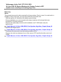
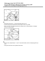
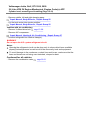
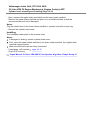
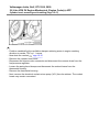
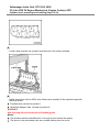
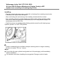
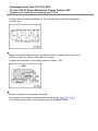
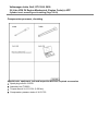
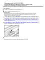
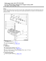
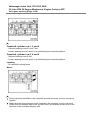
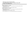
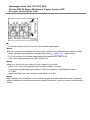
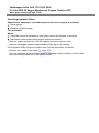
1
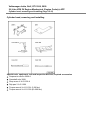
Volkswagen Jetta, Golf, GTI 1999, 2000
2.8 Liter VR6 2V Engine Mechanical, Engine Code(s): AFP
15 Engine- Cylinder head, Valvetrain (Page GR-15)
Cylinder head, removing and installing
Compression pressure, checking
Cylinder head cover, removing and installing
Cylinder head, removing and installing
Valve gear, repairing
Camshafts, removing and installing
Checking hydraulic lifters
Valve guides, checking
Valve guides, replacing
Valve seats, finishing
Valve stem seals, replacing
Volkswagen Jetta, Golf, GTI 1999, 2000
2.8 Liter VR6 2V Engine Mechanical, Engine Code(s): AFP
Cylinder head, removing and installing (Page 15-1)
Checking compression
page 15-23.
Notes:
Use only the assembly tool T10029 for connecting and disconnecting the spark plug
connector.
When installing a replacement cylinder head with installed camshafts, the contact
areas between the valve lifter and the cam track must be oiled after installing the
head.
The supplied plastic open valve protectors should only be removed immediately
before mounting the cylinder head.
When replacing the cylinder head, all of the coolant must be replaced.
Volkswagen Jetta, Golf, GTI 1999, 2000
2.8 Liter VR6 2V Engine Mechanical, Engine Code(s): AFP
Cylinder head, removing and installing (Page 15-2)
1 - Intake manifold-upper
Removing and installing
page 15-8
First, tighten at lower half of manifold, then tighten at both supports
Disassembling and assembling:
Repair Manual, 2.8 Liter VR6 OBD II Fuel Injection & Ignition , Repair Group 24
2 - Retainer
For fuel lines
3 - Throttle with control unit (J338)
May not be opened
With throttle acceleration (G186)
With angle transmitter -1- for throttle acceleration (G187)
With angle transmitter (2) for throttle acceleration (G188)
Heated by coolant
Removing and installing:
Repair Manual, 2.8 Liter VR6 OBD II Fuel Injection & Ignition, Repair Group 24
Volkswagen Jetta, Golf, GTI 1999, 2000
2.8 Liter VR6 2V Engine Mechanical, Engine Code(s): AFP
Cylinder head, removing and installing (Page 15-3)
4 - 10 Nm
5 - Profile gasket
6 - Gasket cover
Replace gasket if damaged
7 - Cylinder head cover
Removing and installing
page 15-8
Replace if damaged or leaking
Coat with D 454 300 A3 before placing the connections cover/cylinder head and the
half moon shaped recess
8 - Gasket for cylinder head cover
Replace if damaged
Note installation position
9 - 25 Nm
Volkswagen Jetta, Golf, GTI 1999, 2000
2.8 Liter VR6 2V Engine Mechanical, Engine Code(s): AFP
Cylinder head, removing and installing (Page 15-4)
10 - Coolant return pump (V51)
Checking
page 19-24
11 - Retainer
12 - Cylinder head
Check for distortion
Fig. 1
Removing and installing
page 15-15
After replacing, replace all of the coolant
13 - O-Ring
Replace
14 - Chain tensioner, 40 Nm
For camshaft roller chain
Turn engine only with installed chain tensioner
15 - Seal ring
Replace
Volkswagen Jetta, Golf, GTI 1999, 2000
2.8 Liter VR6 2V Engine Mechanical, Engine Code(s): AFP
Cylinder head, removing and installing (Page 15-5)
16 - Cover
Can be removed and installed with the cylinder head installed
Coat sealing surfaces with AMV 188 001 02
If only the cover has been removed, prepare the cylinder head gasket for installation
Fig. 2
17 - Ignition coil (N152)
Checking:
Repair Manual, 2.8 Liter VR6 OBD II Fuel Injection & Ignition, Repair Group 01
18 - Cylinder head gasket
Replace
After replacing, replace all of the coolant
Metal gasket
19 - Thermostat housing
Disassembling and assembling
20 - Seal
Replace
page 19-13
Volkswagen Jetta, Golf, GTI 1999, 2000
2.8 Liter VR6 2V Engine Mechanical, Engine Code(s): AFP
Cylinder head, removing and installing (Page 15-6)
21 - Combination valve
Checking
page 26-21
Removing and installing
page 26-31
22 - Seal-upper intake manifold
Replace if damaged
23 - Intake manifold-lower
24 - Seal-lower intake manifold
Replace if damaged
25 - Tensioner
For V-ribbed drive belts
26 - Cylinder head screw
Replace
Note assembly instructions and order when loosening or tightening
27 - Vacuum actuator
For switching of intake manifold runner
page 15-15
Volkswagen Jetta, Golf, GTI 1999, 2000
2.8 Liter VR6 2V Engine Mechanical, Engine Code(s): AFP
Cylinder head, removing and installing (Page 15-7)
Fig. 1 Checking cylinder head for distortion
Special tools, equipment, test and inspection devices; required accessories
Feeler gauge
Max. allowable distortion: 0.1 mm
Fig. 2 Preparing cylinder head gasket for installation
Special tools, equipment, test and inspection devices; required accessories
Sealant AMV 188 001 02
- Clean the 3 mm bores in the cylinder head gasket or cover and sealing flange of old
sealant -arrows-.
- Fill the 3 mm bore in the cylinder head gasket with sealant AMV 188 001 02 and
coat the sealing surfaces on the cover and sealing flange with sealant.
Notes:
With the cylinder head installed, the bores in the cylinder head gasket are only partially visible.
Volkswagen Jetta, Golf, GTI 1999, 2000
2.8 Liter VR6 2V Engine Mechanical, Engine Code(s): AFP
Cylinder head, removing and installing (Page 15-8)
Cylinder head cover, removing and installing
Special tools, equipment, test and inspection devices; required accessories
Installation tool T10029
Torque wrench V.A.G 1331 (5-50 Nm)
Spring band clamp pliers V.A.G 1921
Volkswagen Jetta, Golf, GTI 1999, 2000
2.8 Liter VR6 2V Engine Mechanical, Engine Code(s): AFP
Cylinder head, removing and installing (Page 15-9)
Removing
Notes:
The ground strap must be disconnected for this procedure. Check to see if a coded radio is
installed. If that is the case, you must first obtain the anti-theft code.
- With the ignition off, disconnect the battery ground strap.
- During installation you must reinstall at the same locations all tie straps that were
loosened or cut during removal.
- Remove the spark plug connector with installation tool T10029 and unclip the
ignition lines:
Repair Manual, 2.8 Liter VR6 OBD II Fuel Injection & Ignition , Repair Group 28
- Remove the engine cover.
Repair Manual, 2.8 Liter VR6 OBD II Fuel Injection & Ignition , Repair Group 28
- Disconnect the connector from the heating resistor (N79).
- Remove the inlet hose between the air flow sensor (G70) and the throttle control unit
(J338).
Repair Manual, 2.8 Liter VR6 OBD II Fuel Injection & Ignition , Repair Group 24
Volkswagen Jetta, Golf, GTI 1999, 2000
2.8 Liter VR6 2V Engine Mechanical, Engine Code(s): AFP
Cylinder head, removing and installing (Page 15-10)
- Disconnect connector -1- from the throttle control unit -2.
- Unscrew the ground connection at the throttle control unit (J338).
- Open and close the balancing reservoir sealing cover to allow pressure to escape
from the cooling system.
- Remove the coolant hoses -1- and -2- from the throttle control unit and plug the hose
ends.
- Unclip the fuel lines at the cylinder head cover.
Volkswagen Jetta, Golf, GTI 1999, 2000
2.8 Liter VR6 2V Engine Mechanical, Engine Code(s): AFP
Cylinder head, removing and installing (Page 15-11)
- Now disconnect the vacuum connectors -arrows-.
- Unclip the secondary air pump inlet line and all other lines out of the brackets at the
top half of the intake manifold.
- Unscrew the dipstick duct at the top half of the intake manifold.
- Now unscrew the two intake manifold support screws.
- Remove the vacuum hose at the intake manifold switching vacuum actuator.
- Disconnect the flow hose -1- (with white marking) and return hose -2- (with blue
marking) and catch the leaking fuel with a clean rag.
Notes:
In order to do this, press the tabs at the hose couplings together.
WARNING!
The fuel system is pressurized. Before opening the system, plane a clean rag around the
connection. Then reduce pressure by carefully and slowly loosening the connection.
- Plug the lines so that dirt cannot enter the fuel system.
Volkswagen Jetta, Golf, GTI 1999, 2000
2.8 Liter VR6 2V Engine Mechanical, Engine Code(s): AFP
Cylinder head, removing and installing (Page 15-12)
- Remove middle, left and right damping pans:
Repair Manual, Body-Exterior , Repair Group 50
- Put the lock carrier into service position:
Repair Manual, Body-Exterior , Repair Group 50
Vehicles with air conditioning
- Remove V-ribbed drive belt
page 13-28.
- Remove A/C compressor:
Repair Manual, Heating & Air Conditioning , Repair Group 87
- Unscrew refrigerant line retainer clamp(s).
WARNING!
Do not open the A/C system refrigerant circuit.
Notes:
Opening the refrigerant circuit can be done only in shops which have available
properly trained personel as well as all of the necessary tools and equipment.
To avoid damage to the condenser, coolant lines and hoses, make sure that the
lines and hoses are not being over-stretched, crimped or bent.
Continued for all vehicles
- Remove the combination valve
page 26-31
Volkswagen Jetta, Golf, GTI 1999, 2000
2.8 Liter VR6 2V Engine Mechanical, Engine Code(s): AFP
Cylinder head, removing and installing (Page 15-13)
- Next, unscrew the upper intake manifold from the lower intake manifold.
- Remove the upper intake manifold and place it on a suitable surface so that the
vacuum actuator will not be damaged.
Notes:
Plug the intake ducts in the lower intake manifold or cylinder head with a clean rag.
- Remove the cylinder head cover.
Installing
The installation takes place in the reverse order.
Notes:
If damaged or leaking, replace cylinder head cover.
First, screw the upper intake manifold to the lower intake manifold, then tighten both
manifold support screws.
Make sure the fuel hoses are firmly connected.
- If necessary, refill coolant
page 19-15.
- Check DTC memory.
Repair Manual, 2.8 Liter VR6 OBD II Fuel Injection & Ignition , Repair Group 01
Volkswagen Jetta, Golf, GTI 1999, 2000
2.8 Liter VR6 2V Engine Mechanical, Engine Code(s): AFP
Cylinder head, removing and installing (Page 15-14)
- Adjust basic settings.
Repair Manual, 2.8 Liter VR6 OBD II Fuel Injection & Ignition , Repair Group 24
- Check the readiness code.
Repair Manual, 2.8 Liter VR6 OBD II Fuel Injection & Ignition , Repair Group 01
- If the error memory was erased or the engine control unit was disconnected from the
positive continuous voltage feed, regenerate the readiness code:
Repair Manual, 2.8 Liter VR6 OBD II Fuel Injection & Ignition , Repair Group 01
Tightening torque
Volkswagen Jetta, Golf, GTI 1999, 2000
2.8 Liter VR6 2V Engine Mechanical, Engine Code(s): AFP
Cylinder head, removing and installing (Page 15-15)
Cylinder head, removing and installing
Special tools, equipment, test and inspection devices; required accessories
Suspension device 2024 A
Camshaft ruler 3268
Shop crane V.A.G 1202 A
Drip pan V.A.G 1306
Torque wrench V.A.G 1331 (5-50 Nm)
Torque wrench V.A.G 1332 (40-200 Nm)
Volkswagen Jetta, Golf, GTI 1999, 2000
2.8 Liter VR6 2V Engine Mechanical, Engine Code(s): AFP
Cylinder head, removing and installing (Page 15-16)
Spring band clamp pliers V.A.G 1921
Prerequisites
The engine must not be warmer than hand temperature.
Removing
Notes:
The ground strap must be disconnected for this procedure. Check to see if a coded radio is
installed. If that is the case, you must first obtain the anti-theft code.
- With the ignition off, disconnect the battery ground strap.
- Remove the upper half of the intake manifold
page 15-8.
- Loosen or disconnect the following components:
High voltage line from the ignition coil
Ground strap at the ignition coil
Volkswagen Jetta, Golf, GTI 1999, 2000
2.8 Liter VR6 2V Engine Mechanical, Engine Code(s): AFP
Cylinder head, removing and installing (Page 15-17)
- Position crankshaft at the oscillation damper retaining screw in engine cranking
direction to marker TDC cyl. 1 -arrow.
- Now drain the coolant
page 19-15.
- Remove the cylinder head cover.
- Disconnect the injector valve connector and disconnect the vacuum hose from the
fuel pressure regulator.
- Loosen the spring band clamps and disconnect the coolant hoses from the
thermostat housing.
- Remove the thermostat housing.
- Next, remove the electrical coolant return pump (V51) from its retainer. The coolant
hoses may remain connected.
Volkswagen Jetta, Golf, GTI 1999, 2000
2.8 Liter VR6 2V Engine Mechanical, Engine Code(s): AFP
Cylinder head, removing and installing (Page 15-18)
- Disconnect the three-wire Hall generator sensor (G40) -arrow-; do not remove the
sensor.
- Remove the ignition coil (N152).
- Remove the camshaft roller chain chain tensioner.
- Unscrew the camshaft cover.
- Loosen the camshaft sprockets, however, while doing this, hold the camshafts in
place with fork wrench SW24.
Notes:
Use only fork wrench SW 24 -arrow- to press against camshaft. Camshaft ruler 3268 cannot be
installed when tightening or loosening the sprockets.
- Remove camshaft sprockets.
- Remove the camshaft roller chain track.
- Unscrew the exhaust pipe front from the exhaust manifold
page 26-1.
Volkswagen Jetta, Golf, GTI 1999, 2000
2.8 Liter VR6 2V Engine Mechanical, Engine Code(s): AFP
Cylinder head, removing and installing (Page 15-19)
- Loosen and unscrew the cylinder head screws in the order indicated.
- Install suspension device 2024 A as follows and carefully lift the cylinder head with
the shop crane.
Flywheel side: rail end in position 1
Oscillation damper side: rail end in position 8
WARNING!
Use securing clips at hooks and rail retaining pins.
Notes:
The bracket markers identified with 1 through 4 point toward the pulley.
The bores in the perforated rails are counted starting from the hook.
Volkswagen Jetta, Golf, GTI 1999, 2000
2.8 Liter VR6 2V Engine Mechanical, Engine Code(s): AFP
Cylinder head, removing and installing (Page 15-20)
Installing
- Plug the cylinder with clean rags, so that dirt or shavings from sanding cannot enter
in between the cylinder face and piston.
- Also avoid letting dirt and shavings from sanding contaminate the coolant.
- Next, carefully clean the cylinder head and cylinder block sealing surfaces. Make
sure not to create long grooves or scratches (if you are using abrasive paper, its
coarseness must be over 100)
- Carefully remove any grinding and polishing residue as well as all cleaning rags.
If piston cylinder 1 is not in TDC position:
- Position crankshaft at the oscillation damper retaining screw in engine cranking
direction to marker TDC cyl. 1-arrow.
Notes:
Do not take the new cylinder head gasket out of its packaging until immediately
before installation.
Use extreme care when handling the new gasket. Damage results in leaks.
Volkswagen Jetta, Golf, GTI 1999, 2000
2.8 Liter VR6 2V Engine Mechanical, Engine Code(s): AFP
Cylinder head, removing and installing (Page 15-21)
- Position the new cylinder head gasket. You must be able to read the writing (part
number) on it.
- Make sure that the fitting sleeves have been seated in cylinder head bolt bores 12
and 20 and that the cylinder head gasket is in place.
- Position the camshafts in the cylinder head to cylinder 1 TDC.
- Fasten camshafts with camshaft ruler 3268.
- Next, prepare the cylinder head gasket for installation
page 15-7 , Fig. 2.
- Put cylinder head in place, and manually start cylinder head screws.
Volkswagen Jetta, Golf, GTI 1999, 2000
2.8 Liter VR6 2V Engine Mechanical, Engine Code(s): AFP
Cylinder head, removing and installing (Page 15-22)
- Tighten cylinder head screws as follows in order shown.
- Next, tighten all screws to 50 Nm.
- Next, turn all screws 1 / turn (90 ) with a rigid wrench.
4
- Finally, turn all screws by another 1 / turn (90 ).
4
The remaining assembly occurs in reverse order of removal.
Notes:
Make sure that the oil duct seal O-ring is placed into the cover.
How to adjust the timing
page 13-10.
How to refill new coolant
page 19-15.
Notes:
Retightening of the cylinder head screws is not necessary after repairs.
Volkswagen Jetta, Golf, GTI 1999, 2000
2.8 Liter VR6 2V Engine Mechanical, Engine Code(s): AFP
Cylinder head, removing and installing (Page 15-23)
Compression pressure, checking
Special tools, equipment, test and inspection devices; required accessories
Spark plug wrench 3122 B
Assembly tool T10029
Torque wrench V.A.G 1331 (5-50 Nm)
Compression pressure tester V.A.G 1763
Volkswagen Jetta, Golf, GTI 1999, 2000
2.8 Liter VR6 2V Engine Mechanical, Engine Code(s): AFP
Cylinder head, removing and installing (Page 15-24)
Test condition
Engine oil temperature must be at least 30 C.
Battery voltage must be at least 11.5 V.
Test procedure
- Disconnect the connector from the heating resistor (N79) and remove the intake
hose between the upper half of the air filter and the throttle control unit (J338)
together with the crankcase purge valve:
Repair Manual, 2.8 Liter VR6 OBD II Fuel Injection & Ignition , Repair Group 24
- Use assembly tool T10029 to remove the spark plug connector and the ignition lines:
Repair Manual, 2.8 Liter VR6 OBD II Fuel Injection & Ignition , Repair Group 28
- Remove the engine cover.
Repair Manual, 2.8 Liter VR6 OBD II Fuel Injection & Ignition , Repair Group 28
- Remove spark plugs with spark plug tool 3122 B.
- Disconnect the 5-pin connector from the ignition coil (N152).
Volkswagen Jetta, Golf, GTI 1999, 2000
2.8 Liter VR6 2V Engine Mechanical, Engine Code(s): AFP
Cylinder head, removing and installing (Page 15-25)
- Disconnect fuse no. 32 from the fuse block.
Notes:
By removing fuse 32, the voltage feed to the injector valves is interrupted.
- Completely depress accelerator pedal for wide open throttle.
- Check compression pressure with compression pressure tester V.A.G 1763.
Notes:
Handling the tester
user manual.
- Crank the engine until the tester no longer shows an increase in pressure.
Compression pressure readings:
Volkswagen Jetta, Golf, GTI 1999, 2000
2.8 Liter VR6 2V Engine Mechanical, Engine Code(s): AFP
Valve gear, repairing (Page 15-26)
Notes:
If cracks are small, and no more than 0.5 mm wide, cylinder heads with cracks between the valve
seats or between the valve seat ring and the spark plug thread can continue to be used without a
reduction in life.
1 - Bearing cover
Installation position
Order of installation
Fig. 2
page 15-34
2 - 20 Nm
3 - Camshafts
Checking axial clearance
Fig. 1
Installing and removing
page 15-34
Check radial clearance using Plastigage. Max. wear: 0.10 mm
Runout: max. 0.01 mm
4 - Camshaft sprocket
Removing and installing
page 15-34
Volkswagen Jetta, Golf, GTI 1999, 2000
2.8 Liter VR6 2V Engine Mechanical, Engine Code(s): AFP
Valve gear, repairing (Page 15-27)
5 - Pickup wheel
For Hall generator (G40)
Contact area at camshaft sprocket and pickup wheel must be dry during installation
Removing and installing
page 15-34
6 - 100 Nm
Place against camshaft using fork wrench SW 24 for removal and installation
page 15-34
Oil screw head contact area during installation
7 - Cylinder head height
Min. height: a = 139.5
8 - Cylinder head
Observe Note
page 15-26
Finishing valve seats
page 15-31
9 - Valves
Do not finish, only grinding is allowable
Valve measurements
Fig. 3
Volkswagen Jetta, Golf, GTI 1999, 2000
2.8 Liter VR6 2V Engine Mechanical, Engine Code(s): AFP
Valve gear, repairing (Page 15-28)
10 - Valve guide
Checking
page 15-41
Replacing
page 15-42
Repair guide with collar
11 - Valve stem seal
Replacing
page 15-44
12 - Valve springs
Removing and installing:
With cylinder head removed: use 2037
With cylinder head installed:
page 15-44
13 - Valve spring retainer
14 - Valve collets
15 - Valve lifters
Do not mix up
With hydraulic valve clearance balancing
Checking
page 15-39
For storage, lay down with the running face facing down
Prior to installation, check camshaft axial clearance
Oil running face
Fig. 1
Volkswagen Jetta, Golf, GTI 1999, 2000
2.8 Liter VR6 2V Engine Mechanical, Engine Code(s): AFP
Valve gear, repairing (Page 15-29)
Fig. 1 Camshafts, checking axial clearance
Special tools, equipment, test and inspection devices; required accessories
Universal gauge retainer VW 387
Gauge
Test procedure
Max. wear: 0.15 mm
Measure with valve lifters removed and first and last bearing cover of each camshaft installed.
Fig. 2 Installation position camshaft bearing cover
The bearing cover markings (arrows) must point toward the oscillation damper side.
Volkswagen Jetta, Golf, GTI 1999, 2000
2.8 Liter VR6 2V Engine Mechanical, Engine Code(s): AFP
Valve gear, repairing (Page 15-30)
Fig. 3 Valve measurements
Notes:
Do not finish valves. Only grinding is allowable.
Volkswagen Jetta, Golf, GTI 1999, 2000
2.8 Liter VR6 2V Engine Mechanical, Engine Code(s): AFP
Valve gear, repairing (Page 15-31)
Valve seats, finishing
Necessary special tools, operating equipment, testers, gauges and other aids
Depth gauge
Valve seat finishing tool
Procedure
Notes:
When repairing engines with leaking valves it is not sufficient to just work on or
replace valve seats and valves. With longtime engines in particular it is necessary to
check valve guides for wear.
Only finish valve seats until a correct contact pattern is achieved. Before finishing
valve seats you need to calculate the allowable finishing measurement. If this
measurement is exceeded, correct functioning of the hydraulic valve clearance
balancing cannot be guaranteed and you must replace the cylinder head.
Calculating the maximum allowable finishing measurement
- Insert valve and press firmly against the valve seat.
Volkswagen Jetta, Golf, GTI 1999, 2000
2.8 Liter VR6 2V Engine Mechanical, Engine Code(s): AFP
Valve gear, repairing (Page 15-32)
Notes:
If the valve is being replaced during repairs, use a new valve for measuring.
- Measure distance -a- between valve stem end and upper edge of cylinder head.
- Calculate the maximum allowable finishing measurement from measured distance
and minimum measurement.
Minimum measurements:
Intake valve: 33.9 mm
Exhaust valve: 34.1 mm
Measured distance -a- minus minimum measurement = max. allowable finishing measurement.
Example:
Volkswagen Jetta, Golf, GTI 1999, 2000
2.8 Liter VR6 2V Engine Mechanical, Engine Code(s): AFP
Valve gear, repairing (Page 15-33)
Finishing intake valve seat
Finishing exhaust valve seat
Volkswagen Jetta, Golf, GTI 1999, 2000
2.8 Liter VR6 2V Engine Mechanical, Engine Code(s): AFP
Valve gear, repairing (Page 15-34)
Camshafts, removing and installing
Special tools, equipment, test and inspection devices; required accessories
Camshaft ruler 3268
Torque wrench V.A.G 1331 (5-50 Nm)
Volkswagen Jetta, Golf, GTI 1999, 2000
2.8 Liter VR6 2V Engine Mechanical, Engine Code(s): AFP
Valve gear, repairing (Page 15-35)
Removing
- Turn camshaft in engine turning direction to marker TDC cyl. 1 -arrow- at the
oscillation damper retainer screw.
- Remove ignition coil (N152).
- Remove camshaft roller chain tensioner.
- Remove cover.
- Loosen fastening screws at the camshaft sprockets.
Notes:
Use only fork wrench SW 24 to place against camshaft -arrow-. The camshaft ruler 3268 must not
be inserted when tightening or loosening the sprockets.
- Remove camshaft sprockets.
Volkswagen Jetta, Golf, GTI 1999, 2000
2.8 Liter VR6 2V Engine Mechanical, Engine Code(s): AFP
Valve gear, repairing (Page 15-36)
Camshaft, cylinder row 1, 3 and 5
- Remove bearing covers 1 and 7 first.
- Loosen bearing covers 3 and 5 in an alternating and crosswise pattern.
Camshaft, cylinder row 2, 4 and 6
- Remove bearing cover 4 first.
- Loosen bearing covers 2 and 6 in an alternating and crosswise pattern.
Installing
- Oil camshaft running faces.
Notes:
During camshaft installation, the camshaft sprocket recesses -arrows- must point
upward.
Make sure that during bearing cover installation the markings on the covers are
visible from the exhaust side of the cylinder head, and that the arrows point in the
direction of the oscillation damper side.
Volkswagen Jetta, Golf, GTI 1999, 2000
2.8 Liter VR6 2V Engine Mechanical, Engine Code(s): AFP
Valve gear, repairing (Page 15-37)
Camshaft, cylinder row 1, 3 and 5
- Tighten bearing covers 3 and 5 in an alternating and crosswise pattern and then
finish tightening to 20 Nm.
- Install bearing covers 1 and 7 and also tighten to 20 Nm.
Camshaft, cylinder row 2, 4 and 6
- Tighten bearing covers 2 and 6 in an alternating and crosswise pattern and then
finish tightening to 20 Nm.
- Install bearing cover 4 and also tighten to 20 Nm.
- Clean camshaft gear cover at the sealing surfaces and at the cylinder head.
Volkswagen Jetta, Golf, GTI 1999, 2000
2.8 Liter VR6 2V Engine Mechanical, Engine Code(s): AFP
Valve gear, repairing (Page 15-38)
- Clean old sealant from 3 mm bores in the cylinder head gasket.
Notes:
With the cylinder head installed, the bores in the cylinder head gasket are only partially visible.
- Install camshaft sprockets with camshaft roller chain
page 13-10 , adjust timing.
- Fill 3 mm bores in the cylinder head gasket with sealant AMV 188 001 02.
- Coat cover sealing surface with AMV 188 001 02.
Notes:
Make sure that the oil duct sealing O-ring is seated in the cover.
- Install cover, start all fastening screws and lightly tighten by hand.
- First tighten the M8 fastening screws to 25 Nm, then tighten the M6 fastening screws
to 10 Nm.
- Install camshaft roller chain tensioner and tighten to 30 Nm.
Notes:
After installing new valve lifters, do not start the engine until after about 30 minutes. Hydraulic
balancing elements must become properly seated (otherwise, valves will make contact with the
piston).
Volkswagen Jetta, Golf, GTI 1999, 2000
2.8 Liter VR6 2V Engine Mechanical, Engine Code(s): AFP
Valve gear, repairing (Page 15-39)
Checking hydraulic lifters
Special tools, equipment, test and inspection devices; required accessories
Feeler gauge
Wooden or plastic wedge
Test procedure
Notes:
Valve lifters must be replaced as units (they cannot be adjusted or repaired).
Intermittent valve noises during engine startup are normal.
- Start the engine and let it run until the radiator fan has turned on once.
- Increase the engine speed to approximately 2500 rpm for 2 minutes.
If the hydraulic lifters continue to make noise, find the faulty lifter as follows:
- Remove the cylinder head cover
page 15-8.
- Turn the camshaft at the oscillating damper fastening screw clockwise until the valve
lifter cams being tested are in the upper position.
Volkswagen Jetta, Golf, GTI 1999, 2000
2.8 Liter VR6 2V Engine Mechanical, Engine Code(s): AFP
Valve gear, repairing (Page 15-40)
- Determine the clearance between cams and valve lifters.
- If the clearance is greater than 0.2 mm, replace the valve lifters. If the clearance is
less then 0.1 mm or no clearance is determined, continue the test as follows:
- Push the valve lifters downward with a wooden or plastic wedge. If you can feel
unrestricted motion of more than 0.2 mm until the valve opens, replace lifters.
Notes:
After installing new valve lifters, do not start the engine until after about 30 minutes. Hydraulic
balancing elements must become properly seated (otherwise, valves will make contact with the
piston).
Volkswagen Jetta, Golf, GTI 1999, 2000
2.8 Liter VR6 2V Engine Mechanical, Engine Code(s): AFP
Valve gear, repairing (Page 15-41)
Valve guides, checking
Special tools, equipment, test and inspection devices; required accessories
Universal gauge retainer VW 387
Gauge
Test procedure
- Insert a new valve into the guide. Valve stem end must be flush with the guide.
Because of the varying stem diameters, use only intake valves in intake guides and
exhaust valves in exhaust guides.
- Determine tilt clearance.
Max. wear:
Intake valve guide = 1.0 mm
Exhaust valve guide = 1.3 mm
Volkswagen Jetta, Golf, GTI 1999, 2000
2.8 Liter VR6 2V Engine Mechanical, Engine Code(s): AFP
Valve gear, repairing (Page 15-42)
Valve guides, replacing
Special tools, equipment, test and inspection devices; required accessories
Hand reamer 3120 and diluted soluble oil
3121 Driver
Volkswagen Jetta, Golf, GTI 1999, 2000
2.8 Liter VR6 2V Engine Mechanical, Engine Code(s): AFP
Valve gear, repairing (Page 15-43)
Removing
- Clean and check cylinder head. Heads whose valve seat rings cannot be finished
any further, or heads which have already been finished to the minimum
measurement (height
page 15-27 , item -7-), or which already have KD valve
guides installed, are unsuitable for valve guide replacement.
- Press worn valve guides out from the camshaft side by using driver 3121.
Installing
- Sprinkle new guides with oil and press them up to the sleeve into the cold cylinder
head. The cylinder head must be laying down flat during this procedure.
Notes:
After the guide is in place with the sleeve, the pressure of pressing down cannot exceed 1.0 t,
otherwise the sleeve might break off.
- Ream the valve guide with hand reamer 3120. You must use diluted soluble oil
during this procedure.
- Finish valve seats
page 15-31.
Volkswagen Jetta, Golf, GTI 1999, 2000
2.8 Liter VR6 2V Engine Mechanical, Engine Code(s): AFP
Valve gear, repairing (Page 15-44)
Valve stem seals, replacing
(Cylinder head installed)
Special tools, equipment, test and inspection devices; required accessories
Mounting device 2036
Extruder 3047 A
Spark plug wrench 3122B
Press down device 3129
Mounting lever VW 541/1A
Thrust piece VW 541/5
Volkswagen Jetta, Golf, GTI 1999, 2000
2.8 Liter VR6 2V Engine Mechanical, Engine Code(s): AFP
Valve gear, repairing (Page 15-45)
Flexible pressure tubing VW 653/3
Removing
- Remove camshafts
page 15-34.
- Remove valve lifters (do not mix up) and place aside with the running face facing
down.
- Remove spark plugs with spark plug wrench 3122 B.
- Bring the piston of each applicable cylinder into the "Bottom Dead Center" (BDC)
position.
- Insert mounting device 2036 and adjust the bearing arrangement to the stud bolt
height.
- Screw the flexible pressure tubing VW 653/3 into the spark plug thread and provide
continuous pressure (min. 6 bar).
- Remove the valve springs with mounting lever VW 541/1A and thrust piece VW
541/5.
Notes:
Loosen binding valve collets (keepers) by applying light hammer blows to the mounting lever.
- Remove valve stem seals using extruder 3047 A.
Volkswagen Jetta, Golf, GTI 1999, 2000
2.8 Liter VR6 2V Engine Mechanical, Engine Code(s): AFP
Valve gear, repairing (Page 15-46)
Installing
- To avoid damage to the new valve stem seals, push plastic sleeve -A- onto the valve
stem.
- Oil valve stem seal -B-, insert it into the press down device 3129 and carefully push
onto the valve guide.