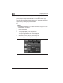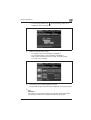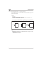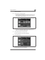
1
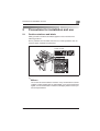
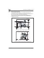
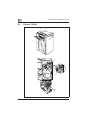
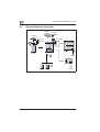
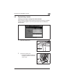
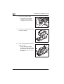
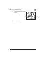
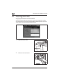
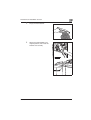
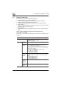
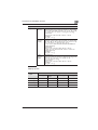
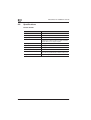
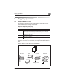
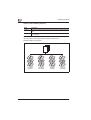
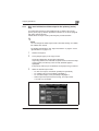
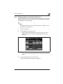
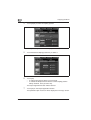
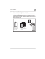
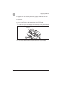
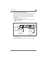
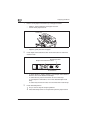
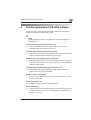
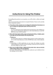
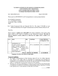
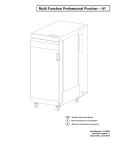
Océ User manual
Océ FS-520
User manual
Océ-Technologies B.V.
Océ-Technologies B.V.
Copyright
¤ 2007, Océ-Technologies B.V. Venlo, The Netherlands.
All rights reserved. No part of this work may be reproduced, copied, adapted, or
transmitted in any form or by any means without written permission from Océ.
Océ-Technologies B.V. makes no representation or warranties with respect to the
contents hereof and specifically disclaims any implied warranties of
merchantability or fitness for any particular purpose.
Further, Océ-Technologies B.V. reserves the right to revise this publication and to
make changes from time to time in the content hereof without obligation to notify
any person of such revision or changes.
Edition 2007-08
GB
Trademarks
Trademarks
Océ, Océ FS-520, Océ Doc Exec£,
Océ Image Logic£, Océ Scan Logic£, Océ Power Logic£, Océ Print Exec£ and Océ
Remote Logic£ are registered trademarks of Océ-Technologies B.V.
Adobe£ and PostScript£ 3¥ are registered trademarks of Adobe£ Systems
Incorporated.
Macintosh£ is a registered trademark of Apple£ Computer, Inc.
Microsoft£, Windows£ , Windows NT£, Windows 95/98£, Windows 2000£,
Windows XP£ and Internet Explorer£ are either registered trademarks or trademarks
of Microsoft£ Corporation in the United States and/or other countries.
AutoCAD£ is a registered trademark of Autodesk, Inc.
Novell£ is a registered trademark of Novell, Inc.
Netscape Navigator£ is a registered trademark of Netscape Corp.
Pentium£ is a registered trademark of Intel Corporation.
Energy STAR£ is a registered trademark of the U.S. Environmental Protection
Agency (EPA).
Products in this publication are referred to by their general trade names. In most, if
not all cases, these designations are claimed as trademarks or registered trademarks
of their respective companies.
Trademarks
Contents
1
Introduction
2
Precautions for installation and use
3
2.1
Caution notations and labels........................................................... 2-3
2.2
Space requirements ......................................................................... 2-4
2.3
Finisher FS-520 ................................................................................. 2-6
2.4
Standard/optional equipment.......................................................... 2-8
2.5
Replenishing staples ........................................................................ 2-9
Inserting a new staple cartridge into Finisher FS-520 ................... 2-9
2.6
Disposing punch waste.................................................................. 2-12
Emptying waste basket of Finisher FS-520 ................................. 2-12
2.7
Paper information ........................................................................... 2-14
2.8
Specifications ................................................................................. 2-16
Finisher FS-520............................................................................ 2-16
Copying operations
3.1
3.1.1
Using Finisher FS-520 ...................................................................... 3-3
Output to the primary (main) tray ................................................... 3-3
Output to the secondary (sub) tray ................................................ 3-4
Non-sort/collate/uncollate output to the primary (main) tray......... 3-5
3.1.2
Stapling output to the primary (main) tray ..................................... 3-7
3.1.3
Collate/uncollate output to the secondary (sub) tray................... 3-10
3.1.4
Punching file holes in copies (Punch) .......................................... 3-12
3.2
Cover sheet feeding (paper inserter) ............................................ 3-15
3.3
Using Finisher FS-520 manually .................................................... 3-17
FS-520
Contents-1
4
Finisher adjustment (FS-520) outlines
03 Punch Adjustment/01 Vertical Position Adj. .............................. 4-3
03 Punch Adjustment/02 Horizontal Position Adj,.......................... 4-3
03 Punch Adjustment/03 Registration Adjustment......................... 4-3
03 Punch Adjustment/04 Paper Edge Detect Sensor Adj. ............. 4-3
06 Paper Inserter Tray Size Adj. ..................................................... 4-3
07 Output Quantity Limit................................................................. 4-3
08 Curl Adjustment ......................................................................... 4-3
Contents-2
FS-520
1
Introduction
Introduction
1
1
Introduction
Finisher FS-520 is an optional device newly added to the configuration of
CS650 options.
Please refer to this manual for the operation and safety information on the
finisher, and keep this manual inside the user manual of the main body,
readily available for reference.
Also, be sure to read Chapter 1 "Introduction/Safety Information" of the
CS650 User manual.
Océ AG
FS-520
1-3
1
1-4
Introduction
FS-520
2
Precautions for
installation and use
Precautions for installation and use
2
2
Precautions for installation and use
2.1
Caution notations and labels
Safety precaution notations and labels appear on this machine at the
following positions.
Be very careful that an accident does not occur when operations such as
removing paper misfeeds are performed.
Finisher FS-520
2
Reminder
Do not remove caution labels or notations. If any caution label or caution
notation is soiled, please clean to make legible. If you cannot make them
legible, or if the caution label or notation is damaged, please contact your
service representative.
FS-520
2-3
Precautions for installation and use
2
2.2
Space requirements
To ensure that machine operation, consumables replenishing, part
replacement, and regular maintenance can easily be performed, adhere to
the recommended space requirements detailed below.
Be sure to choose a level and solid floor for the installation place.
Combination size the main body and options may be different for the
installation environment.
Unit: mm
205
393
1619
1177
1021
1160
85
100
410
760
718
100
656
2419
Main body + DF-609 + LU-202 + FS-520 + PI-502
1619
1021
899
950
293
2142
Main body + DF-609 + LU-202 + FS-520 + PI-502 (side-view)
2-4
FS-520
Precautions for installation and use
2
2
Reminder
Be sure to allow a clearance of 200 mm or more at the back of this
machine for the ventilation duct.
FS-520
2-5
Precautions for installation and use
2
2.3
Finisher FS-520
2
3
1
1
2
4
5
3
6
7
2-6
FS-520
Precautions for installation and use
2
External view
No.
Name
Description
1
Finisher door
Opens to the internal finisher to allow clearing mishandled paper, replenishing staples, and emptying waste
basket of punch kit.
2
Primary (Main) tray
Holds sets output in Non-sort mode, Collate mode (offset), or Staple mode.
3
Secondary (Sub) tray
Holds sets output in Non-sort mode.
Internal view
FS-520
No.
Name
Description
1
Secondary (Sub) tray conveyance lever
Opens rightward to remove mishandled paper.
2
Paper inserter conveyance
lever
Opens leftward to remove mishandled paper.
3
Punch kit PK-512/PK-513
(option)
Punches file holes in the output copies.
4
Entrance lever
Opens downward to remove mishandled paper.
5
Stacker conveyance lever
Opens lower-leftward to remove mishandled paper.
6
Staple cartridge
Holds staple case to be replaced when supplying staples.
7
Stacker unit handle
Withdraws unit to allow removal of mishandled paper and
replacement of staple cartridge.
2-7
Precautions for installation and use
2
2.4
Standard/optional equipment
DF-609
OC-506
PI-502
key counter
PK-512
PK-513
PF-601
FS-520
main body
HT-504
LU-502
IC-408
IC-303 IC-304
2-8
HT-503
FS-520
Precautions for installation and use
2.5
2
Replenishing staples
Inserting a new staple cartridge into Finisher FS-520
When the staple cartridge of the Finisher FS-520 becomes empty, the Staple
Cartridge indicator lights in red in the option status area of the Machine
Status Screen.
1
Open the Finisher door.
2
Pull out the stacker unit.
–
FS-520
Pull out the stacker unit slowly by
holding the stacker unit handle
until it stops.
2-9
Precautions for installation and use
2
3
Remove the staple cartridge.
–
4
Remove the empty staple case from
the staple cartridge.
5
Insert the new staple case into the
staple cartridge.
–
2-10
Hold the lever on the staple
cartridge, and then pull the
cartridge down to remove it.
Do not remove the staples
remaining inside the cartridge;
otherwise, the first sheet output
after the replenishment will not
be stapled.
FS-520
Precautions for installation and use
FS-520
6
Return the stacker unit to its original
position.
7
Close the Finisher door.
2
2-11
Precautions for installation and use
2
2.6
Disposing punch waste
Emptying waste basket of Finisher FS-520
When the waste basket of Punch kit PK-512/PK-513 installed in Finisher
FS-520 becomes full, the Punch Waste Basket indicator lights in red in the
option status area of the Machine Status Screen.
2-12
1
Open the Finisher door.
2
Withdraw the waste basket.
FS-520
Precautions for installation and use
FS-520
3
Empty the waste basket.
4
Return the waste basket to its
original position, then close the
Finisher door securely.
2
2-13
Precautions for installation and use
2
2.7
Paper information
Finisher FS-520 provides the following functions.
- Straight delivery using primary (main) tray:
Outputs sorted/grouped sets normally to the primary (main) tray.
- Straight delivery using secondary (sub) tray:
Outputs sorted/grouped sets normally to the secondary (sub) tray.
- Offset delivery:
Outputs sorted/grouped sets to the primary (main) tray, having each set
offset by approx. 30 mm upon exit.
- Staple delivery:
Staples each set with one staple at the corner or two staples along the
edge.
Punch mode is available using Finisher FS-520 with Punch kit
PK-512/PK-513 installed.
Sheet insertion is available using Finisher FS-520 with Post inserter PI-502
installed.
Paper information
Primary (main) tray: 60 to 300 g/m2
Secondary (sub) tray: 50 to 300 g/m2
Staple: 60 to 209 g/m2
Weight
Capacity
2-14
Secondary
(sub) tray
Max. 100 sheets
Primary
(main) tray
(normal)
500 sheets (80 g/m2) (A5 w/v, B6 w, 5.5" e 8.5" w/v)
3,000 sheets (80 g/m2) (A4 w/v, B5 w/v, 16K w/v,
8.5" e 11" w/v, 7.25" e 10.5" w/v)
1,500 sheets (80 g/m2) (SRA3w, SRA4w, A3 w, B4 w, Foolscap, 8K w, 12" e 18" w, 11" e 17" w, 8.5" e 14" w, Wide size
(max. 320 mm e 450 mm))
Tray capacity varies depending on paper weight.
• ~80 g/m2 : 1,500 sheets
• 81~135 g/m2 : 1,000 sheets
• 136~209 g/m2 : 700 sheets
• 210~300 g/m2 : 500 sheets
Primary
(main) tray
(Staple)
Max. 50 sheets (80 g/m2) per set
2-9 sheets stapled: 100 sets (150-417mm in length)/ 50 sets
(others)
10-20 sheets stapled: 50 sets
21-30 sheets stapled: 30 sets
31-40 sheets stapled: 25 sets
41-50 sheets stapled: 20 sets
Paper Inserter PI-502
Upper/Lower tray
Max. 200 sheets (50 to 200 g/m2)
Punch Kit
PK-512/
PK-513
Unlimited
FS-520
Precautions for installation and use
2
Paper information
Paper Size
Secondary
(sub) tray
Standard Size:
SRA3 w, SRA4 w/v, A3 w, B4 w, Foolscap, A4 w/v, B5 w/v,
A5 w/v, B6 w, A6 w, 8K w, 16K w/v, 13" e 19" w, 12" e 18" w,
11" e 17" w, 8.5" e 14" w, 8.5" e 11" w/v, 5.5" e 8.5"w/v
Custom Size:
Max. 330 mm e 487 mm to Min. 100 mm e 148 mm
Tab Paper:
A4 v, 8.5" e 11" v
Primary
(main) tray
(Normal)
Standard Size:
SRA3 w*1, SRA4 w, A3 w, B4 w, Foolscap, A4 w/v, B5 w/v,
A5 w*1/v, B6 w*1, 8K w, 16K w/v, 12" e 18" w, 11" e 17" w,
8.5" e 14" w, 8.5" e 11" w/v, 5.5" e 8.5" w*1/v
*1: 5.5" e 8.5" w, SRA3 w, A5 w and B6 w are available for
straight output only.
Custom Size*2:
Max. 314 mm e 458 mm to Min. 182 mm e 148 mm
*2: Max. 314 mm e 458 mm to Min. 128 mm e 148 mm for
straight output only.
Tab Paper:
A4 v, 8.5" e 11" v
Primary
(main) tray
(Staple)
Standard Size:
SRA4 w, A3 w, B4 w, Foolscap, A4 w/v, B5 w/v, A5 v, 8K w,
16K w/v, 12" e 18" w, 11" e 17" w, 8.5" e 14" w,
8.5" e 11" w/v, 5.5" e 8.5" v
Custom Size:
Max. 314 mm e 458 mm to Min. 182 mm e 148 mm
Tab Paper:
A4 v, 8.5" e 11" v
Stapling capacity
Paper
weight
High quality
paper
Colored paper
Coated paper
64 to 80 g/m2
50 sheets
50 sheets
50 sheets
40 sheets
81 to 105 g/m2
40 sheets
30 sheets
30 sheets
25 sheets
to 135 g/m2
30 sheets
30 sheets
25 sheets
20 sheets
136 to 209 g/m2
20 sheets
20 sheets
15 sheets
---
106
FS-520
Paper type
Normal paper
2-15
Precautions for installation and use
2
2.8
Specifications
Finisher FS-520
Item
2-16
Description
Name
FS-520
Finisher type
Offset catch tray
Output tray
Primary (main) and secondary (sub) trays
Function
Straight delivery (collated, uncollated)
Offset delivery (collate and offset, uncollate and offset)
Staple delivery (corner staple, 2 staples)
Paper Types
See page 2-14 for details.
Paper Sizes
See page 2-14 for details.
Paper tray capacity
See page 2-14 for details.
Maximum power consumption
80 W or less
Dimensions
424 (674.5 when primary (main) tray is attached/ 790.5
when the tray is pulled out) (W) e 656 (D) e 990 (H) mm
Weight
Approx. 60 kg
FS-520
3
Copying operations
Copying operations
3
3
Copying operations
3.1
Using Finisher FS-520
The Finisher FS-520 has a primary (main) tray and a secondary (sub) tray,
each of which has the following output modes.
Output to the primary (main) tray
Mode
Description
Non-sort
Non-sort mode simply means that the offset-stacker finisher modes are not selected. Copies will be stacked upon exit without being offset by sorted sets.
Collate
Collate mode outputs multiple copies of the original set, having each sorted set
offset by 30 mm upon exit
Uncollate
Uncollate mode groups together multiple copies of each original and offsets the
sets by 30 mm upon exit.
Staple
Staple mode offsets and staples each sorted set.
Combined with the output modes above except staple mode, you can also
choose to output face up or face down, and output front to back or back to
front.
Example: Make 3 copied sets from 4 original sheets
Non-sort
Staple
Collated
Uncollated
2 staples
1 oblique
staple
FS-520
Offset by 30mm
Offset by 30mm
3-3
Copying operations
3
Output to the secondary (sub) tray
Mode
Description
Collate
Collate mode outputs multiple copies of the original set. No offset output is available.
Uncollate
Uncollate mode groups together multiple copies of each original. No offset output is available.
Combined with the output modes above, you can also choose to output face
up or face down, and output front to back or back to front.
Example: Make 3 copied sets
Face down
collated
3-4
Face down
uncollated
Face up
collated
Face up
uncollated
FS-520
Copying operations
3.1.1
3
Non-sort/collate/uncollate output to the primary (main)
tray
A machine with Finisher FS-520 installed is set to collate output to the
primary (main) tray by default, regardless of whether or not to be equipped
with other optional devices.
Please select an output mode by following the procedures below.
!
Detail
You can change the initial output mode in the Utility setting. For details,
see CS650 User manual.
For detailed specifications, see "Paper information" on page 2-14 and
"Specifications" on page 2-16.
1
Position the original.
2
Touch [Output Appli.] on the Copy Screen.
The Output Application Screen will be displayed.
Output tray positions are indicated as square marks on the front image
of the machine, and the tray mark currently selected appears
highlighted.
If the primary (main) tray is not selected, touch [Output Tray] to select it.
3
Select the desired output mode.
–
–
–
–
FS-520
For Non-sort output, cancel both [Collate] and [Uncollate].
For Collate output, touch [Collate] to highlight it.
For Uncollate output, touch [Uncollate] to highlight it.
Select output face (Face Down/Face Up), and output order
(1 to N/N to 1) as needed.
3-5
Copying operations
3
4
Touch [OK] on the Output Application Screen.
The specified output mode icon will be displayed on the Copy Screen.
2
Reminder
The primary (main) tray gradually goes down while printed materials are
output. DO NOT allow any object to interfere with the operation of the tray
on the left side of the finisher, as any interference may cause damage to
the finisher.
Be careful not to exceed the finisher tray capacity when selecting the
print quantity, otherwise unexpected trouble may be caused.
3-6
FS-520
Copying operations
3.1.2
3
Stapling output to the primary (main) tray
Copies will be stapled in this mode. Follow the procedure below to select the
stapling position and number of staples: Top Left/ Top Right (Corner Staple),
Left/Top/Right (2 Position Staple).
!
Detail
For detailed specifications, see "Paper information" on page 2-14 and
"Specifications" on page 2-16.
1
Position the original.
2
Touch [Staple] on the Copy Screen.
–
Stapled sheets will be delivered to the primary (main) tray. The
Output Application icon shows the stapling position currently
selected.
If you want to change the stapling position, proceed to the following
steps.
3
Touch [Output Appli.] on the Copy Screen.
The Output Application Screen will be displayed.
FS-520
3-7
Copying operations
3
4
Touch [Staple] to select the stapling position.
The Staple Setting Screen will be displayed.
5
Touch the desired stapling position key to select it.
6
Touch [OK].
–
–
To restore the previous setting, touch [Cancel].
To release the Staple function with the current stapling position
setting remained, touch [Function Off].
The Output Application Screen will be restored.
7
Touch [OK] on the Output Application Screen.
The specified output mode icon will be displayed on the Copy Screen.
3-8
FS-520
Copying operations
3
2
Reminder
The primary (main) tray gradually goes down while printed materials are
output. DO NOT allow any object to interfere with the operation of the tray
on the left side of the finisher, as any interference may cause damage to
the finisher.
Be careful not to exceed the finisher tray capacity when selecting the
print quantity, otherwise unexpected trouble may be caused.
FS-520
3-9
Copying operations
3
3.1.3
Collate/uncollate output to the secondary (sub) tray
A machine with Finisher FS-520 installed is set to Collate output to the
primary (main) tray by default, regardless of whether or not to be equipped
with other optional devices. Change the output tray and select the desired
output mode by following the procedure below.
!
Detail
For detailed specifications, see "Paper information" on page 2-14 and
"Specifications" on page 2-16.
1
Position the original.
2
Touch [Output Appli.] on the Copy Screen.
The Output Application Screen will be displayed.
3
Select the secondary (sub) tray as the output tray.
–
3-10
Touch [Output Tray] to display the Output Tray Selection Screen.
FS-520
Copying operations
–
4
of the secondary (sub) tray to
Select the desired output mode.
–
–
–
5
Touch the tray position key
highlight it, then touch [OK].
3
For Collate output, touch [Collate] to highlight it.
For Uncollate output, touch [Uncollate] to highlight it.
Select output face (Face Down/Face Up), and output order
(1 to N/N to 1) as needed.
Touch [OK] on the Output Application Screen.
The specified output mode icon will be displayed on the Copy Screen.
2
Reminder
Be careful not to exceed the finisher tray capacity when selecting the
print quantity, otherwise unexpected trouble may be caused.
FS-520
3-11
Copying operations
3
3.1.4
Punching file holes in copies (Punch)
The Finisher FS-520 with Punch kit PK-512/PK-513 installed can punch file
holes in output copies.
2
Reminder
Do not punch special paper type such as labels, tracing paper, etc.
Otherwise, machine trouble may occur.
Be sure that the side guide plates of the paper tray are securely aligned
to the paper; otherwise the copies may not be punched in position.
80 mm
80 mm
21 mm
70 mm
21 mm
!
Detail
For detailed specifications, see "Paper information" on page 2-14 and
"Specifications" on page 2-16.
3-12
FS-520
Copying operations
1
Position the original.
2
Touch [Punch] on the Copy Screen.
–
3
Punched sheets will be delivered to the primary (main) tray. The
Output Application icon shows the number of punch holes and
punch position currently selected.
If you want to change the number of punch holes and punch
position, proceed to the following steps.
3
Touch [Output Appli.] on the Copy Screen.
The Output Application Screen will be displayed.
4
Touch [Hole-Punch].
The Hole-Punch Screen will be displayed.
FS-520
3-13
Copying operations
3
5
Touch the desired punch key to select it.
6
Touch [OK].
–
–
To restore the previous setting, touch [Cancel].
To release the Punch function with the current number of punch
holes and punch position setting remained, touch [Function Off].
The Output Application Screen will be restored.
7
Touch [OK] on the Output Application Screen.
The specified output mode icon will be displayed on the Copy Screen.
2
Reminder
Be careful not to exceed the finisher tray capacity when selecting the
print quantity, otherwise unexpected trouble may be caused.
3-14
FS-520
Copying operations
3.2
3
Cover sheet feeding (paper inserter)
The Finisher FS-520 with Paper inserter PI-502 installed can attach cover
sheets to output copies.
Using Insert Sheet function, cover sheets loaded in the upper and lower trays
of the paper inserter will be attached as a front cover and/or back cover or
insertion sheet to output copies, and also using Staple mode, a covered and
stapled book can be made.
Cover sheet
Copied set with
cover attached in
staple mode
FS-520
Copied set with
covers and insertions
attached
3-15
Copying operations
3
0 Upper/Lower tray capacity: 200 sheets ( paper) or within 30 mm thick
each
0 Use ADF.
0 The cover paper size should be the same as copy paper size.
0 Cover paper loaded in the paper inserter cannot be copied.
1
Load cover paper into the upper and lower trays of the paper inserter.
Upper tray
Lower tray
2
3-16
Use Insert Sheet function to attach covers to the output copies.
FS-520
Copying operations
3.3
3
Using Finisher FS-520 manually
The Finisher FS-520 with Paper inserter PI-502 installed can be operated
manually, using the operation panel provided on the paper inserter.
Place a set of paper into the lower tray. Upper tray cannot be used.
Available finishing modes according to the optional configuration are
described below.
- Finisher FS-520 + Paper inserter PI-502
– Staple (1 staple/2 staples)
- Finisher FS-520 + Paper inserter PI-502 + Punch kit PK-512/PK-513
– Staple (1 staple/2 staples)
– Punch
Start/Stop button
1 oblique staple
2 parallel staples
Punch
0 Paper should be placed only in the lower tray of the paper inserter. Upper
tray cannot be used.
0 Staple (1 staple/2 staples) and Punch can be used in combination.
FS-520
3-17
Copying operations
3
1
Place a set of paper in the lower tray of the paper inserter.
–
–
Staple (1 staple/2 staples): Place paper face UP.
Punch: Place paper face UP.
Lower tray
–
2
Align the guide plate with the paper.
Press Staple mode selection button and Punch button to select the
desired mode.
Start/Stop button
Staple mode selection button
Punch button
–
–
3
To select Staple (1 staple/2 staples), press Staple mode selection
button to turn on the desired mode lamp.
To select Punch, press Punch button to turn on the lamp.
To use Staple in combination, turn on the desired Staple mode
lamp.
To select only the Punch mode, turn off all the other mode lamps.
Press Start/Stop button.
Do you want to stop the output operation?
% Press Start/Stop button on the operation panel of paper inserter.
?
3-18
FS-520
4
Finisher adjustment
(FS-520) outlines
Finisher adjustment (FS-520) outlines
4
4
Finisher adjustment (FS-520) outlines
Use this function to make the following the fine adjustments on Finisher
FS-520. For details, see CS650 User manual.
!
Detail
The target adjustment items vary depending upon the configuration of
installed options.
03 Punch Adjustment/01 Vertical Position Adj.
%
Perform this adjustment for the center position of punch holes
operated by the Punch Kit PK-512/PK-513.
03 Punch Adjustment/02 Horizontal Position Adj,
%
Perform this adjustment for the position of punch holes in the feeding
direction operated by the Punch Kit PK-512/PK-513.
03 Punch Adjustment/03 Registration Adjustment
%
Perform this adjustment for the skew of the punch position made by
the Punch Kit PK-512/PK-513 in duplex copying or cover sheet feeding
using the paper inserter.
03 Punch Adjustment/04 Paper Edge Detect Sensor Adj.
%
Perform this adjustment to detect the paper edge to be used as
reference point of punching operation.
06 Paper Inserter Tray Size Adj.
%
Perform the size adjustment for the Upper tray and Lower tray of the
Paper Inserter PI-502.
07 Output Quantity Limit
%
Specify the output quantity limit of stapled sets.
08 Curl Adjustment
%
FS-520
This adjustment can be used to adjust the compression fixing amount
of paper exit decurler roller if any crease appears in printed sheets
output from FS-520.
4-3
4
4-4
Finisher adjustment (FS-520) outlines
FS-520