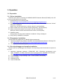
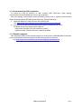
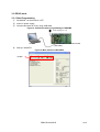
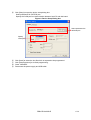
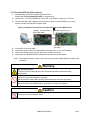
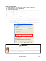
1
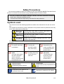
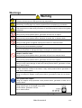
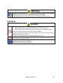
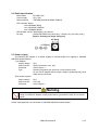
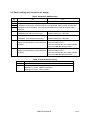
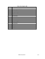
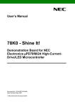
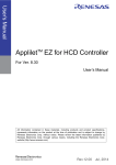
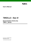
User’s Manual
EZ-0005
78K0/IB2 HBLED Evaluation Board
Target Device
78K0/IB2 Microcontroller
ZBB-CE-09-0009-E
Data Published March 2009
© NEC Electronics Corporation
1/27
The information in this document is current as of March, 2009. The information is subject to change
without notice. For actual design-in, refer to the latest publications of NEC Electronics data sheets or
data books, etc., for the most up-to-date specifications of NEC Electronics products. Not all products
and/or types are available in every country. Please check with an NEC Electronics sales
representative for availability and additional information.
No part of this document may be copied or reproduced in any form or by any means without the prior
written consent of NEC Electronics. NEC Electronics assumes no responsibility for any errors that may
appear in this document.
NEC Electronics does not assume any liability for infringement of patents, copyrights or other
intellectual property rights of third parties by or arising from the use of NEC Electronics products listed
in this document or any other liability arising from the use of such products. No license, express,
implied or otherwise, is granted under any patents, copyrights or other intellectual property rights of
NEC Electronics or others.
Descriptions of circuits, software and other related information in this document are provided for
illustrative purposes in semiconductor product operation and application examples. The incorporation
of these circuits, software and information in the design of a customer's equipment shall be done
under the full responsibility of the customer. NEC Electronics assumes no responsibility for any losses
incurred by customers or third parties arising from the use of these circuits, software and information.
While NEC Electronics endeavors to enhance the quality, reliability and safety of NEC Electronics
products, customers agree and acknowledge that the possibility of defects thereof cannot be
eliminated entirely. To minimize risks of damage to property or injury (including death) to persons
arising from defects in NEC Electronics products, customers must incorporate sufficient safety
measures in their design, such as redundancy, fire-containment and anti-failure features.
NEC Electronics products are classified into the following three quality grades: "Standard", "Special“
and "Specific".
The "Specific" quality grade applies only to NEC Electronics products developed based on a
customer-designated "quality assurance program" for a specific application. The recommended
applications of an NEC Electronics product depend on its quality grade, as indicated below.
Customers must check the quality grade of each NEC Electronics product before using it in a
particular application.
“Standard”: Computers, office equipment, communications equipment, test and measurement
equipment, audio and visual equipment, home electronic appliances, machine tools,
personal electronic equipment and industrial robots.
“Special”: Transportation equipment (automobiles, trains, ships, etc.), traffic control systems,
anti-disaster systems, anti-crime systems, safety equipment and medical equipment (not
specifically designed for life support).
“Specific”: Aircraft, aerospace equipment, submersible repeaters, nuclear reactor control systems,
life support systems and medical equipment for life support, etc.
The quality grade of N EC Electronics products is "Standard" unless otherwise expressly specified in
NEC Electronics data sheets or data books, etc. If customers wish to use NEC Electronics products in
applications not intended by NEC Electronics, they must contact an NEC Electronics sales
representative in advance to determine NEC Electronics' willingness to support a given application.
(Note)
(1)”NEC Electronics” as used in this statement means NEC Electronics Corporation and also includes
its majority-owned subsidiaries.
(2)"NEC Electronics products" means any product developed or manufactured by or for NEC
Electronics (as defined above).
ZBB-CE-09-0009-E
2/27
Safety Precautions
This document explains matters to be noted for safe use of 78K0/IB2 HBLED Evaluation Board.
Be sure to read this document before using 78K0/IB2 HBLED Evaluation Board.
•
•
Be sure to observe all dangers, warnings, cautions, and other instructions contained
herein when using this evaluation board.
This document should be kept handy at all times for ready reference.
Symbols used
This document uses the following symbols for matters to be observed for the safe use of the
unit.
The symbols are followed by a brief explanation of the possible extent of problems which may
occur if the notices are not observed.
Danger
The user may suffer death or serious injury and it’s
risk is high if the warning is not observed.
Warning
The user may suffer death or serious injury if the
warning is not observed.
Caution
Human injury or property damage may occur if the
caution is not observed.
The following symbols express matters which are prohibited in order to prevent injury or
accident.
General prohibition
Do not touch
Do not disassemble
The action mentioned
Touching the
Disassembly may
is prohibited.
specified location
cause a problem such
may cause injury.
as electrical shock or
product failure.
Keep away from
Flammable
Do not touch with
A nearby flame may
water
wet hands
Use near water poses
cause the unit to
Touching with wet
the risk of electrical
catch fire.
hands may cause
shock or product
electric shock or
failure if moisture were
product failure.
to contact the unit.
The following symbols are used for cautions to prevent product failure and accidents.
Caution Hot
General caution
Human injury by high temperature may
Unspecified general cautions.
occur.
The following symbols are used for instructions to prevent product failure and accidents.
Compulsory action based on an
instruction for the user.
ZBB-CE-09-0009-E
Instruction to unplug the AC adapter.
3/27
Warnings
Warning
Be careful to burns.
The part of board around LED becomes high temperature.
Be careful to brightness of LEDs and On/Off period of LEDs.
Stimulating of strong light may cause symptoms such as epilepsy by constitution.
Do not use this board in the purpose except the evaluation of MCU.
This board does not take safety measures or anti-EMI measures required for lighting
equipment.
Do not heat the board or expose it to fire, and do not short the terminals.
Doing so may cause product failure, generation of heat, fire, or rupture.
Do not disassemble or modify the board.
Doing so may cause product failure, emission of smoke, fire, or electric shock.
Do not touch with wet hands.
Doing so while power is supplied cause product failure or electrical shock.
Do not look LEDs on this board directly.
Doing so may cause weakening eyesight.
Do not drop or jolt the board.
Doing so may break or damage the board, causing fire or electric shock.
Do not turn on power switch in insufficient state of cable connection such as AC
adapter, interface cable.
Doing so may cause product failure, generation of heat, fire or electric shock.
Do not plug in or unplug a connector or cable with power applied to the board.
Doing so may cause product failure, generation of heat, fire or rupture.
Do not carry this board with connecting AC adapter and any cable.
Doing so may cause damage of cable and cause product failure, generation of heat,
fire or electric shock.
Use this board with spacer and on the isolated bench.
In case conductor contact to the board, it may cause product failure, generation of
heat, fire or electric shock.
Use AC adapter adapted to safety standard of each county.
Using non-adopt AC adapter cause product failure, generation of heat, fire or electric
shock.
Use specified AC adapter.
Using AC adapter except specified cause product failure, generation of heat, fire or
electric shock.
Use AC adapter with following size and polarity of DC plug.
Using another type of AC adapter may cause
product failure, generation of heat,
fire or electric shock.
Confirm the outlet is near this board and easily unplugged.
ZBB-CE-09-0009-E
4/27
Warning
If smoke or an abnormal smell or sound is emitted, or heating occurs, promptly
switch off the board power and unplug from AC power supply.
Using the board in such a state poses a risk of fire, burning, or electric shock.
Cautions
Caution
Do not use or store this board in any of the following locations.
- Environments with copious water, humidity, steam, dust, fumes, etc.
- Environments where static electricity or electrical noise is readily generated.
Such influences can lead to electric shock or product failure.
In case liquid enters the board, cut the power supply, and consult your dealer or NEC
Electronics sales representative.
Even if the unit appears to be dry, internal moisture may remain.
Do not touch LEDs on this board directly.
Doing so may cause product failure.
To prevent static electricity damage, guard against energizing when touching
metal parts such as the connector.
Static electricity can cause product failure.
ZBB-CE-09-0009-E
5/27
CONTENTS
CHAPTER 1
OVERVIEW ………………………………………………………… 7
CHAPTER 2
SPECTIFICATION …………………………………………………
CHAPTER 3
OPERATION …………………………………………………………14
9
APPENDIX A SCHEMATICS ……………………………………………………… 24
APPENDIX B REVISION HISTORY ……………………………………………… 26
ZBB-CE-09-0009-E
6/27
1. Overview
78K0/IB2 HBLED Evaluation Board is an evaluation kit for high brightness LED application
using the 78K0/IB2 microcontroller.
This board can operate by DC5V power supply provided from AC adapter. Please prepare AC
adapter by yourself.
78K0/IB2 controls current of the high brightness LED to be constant. It can also control the
evaluation board operating with analog input. When connecting with a Lighting Communication
Master Evaluation Board (EZ-0008), LEDs can be controlled to dim with DMX512 protocol or DALI
protocol.
Figure 1. System setup example (OCD mode / DALI protocol control)
Power supply (5V, >1A)
Lighting Communication Board
(Please prepare by yourself)
(EZ-0008)
DALI
Host PC
78K0/IB2 HBLED Evaluation board
Programming/OCD
(EZ-0006)
1.1 Feature
・ 3 channels constant current control without driver IC but only a 78K0/IB2 microcontroller
Buck topology
300mA per channel
5V supply voltage
・ Up to 3 kind of control interface supported
DMX512 protocol communication interface
DALI protocol communication interface
Analog volume control interface
・ Programming / On-chip debug supported
1.2 Operation Mode
・ PROG mode
Flash programming through the USB interface
・ RUN mode
Three control interfaces are offered on this board.
DMX512 protocol control interface
DALI protocol control interface
Analog volume control interface
・ On-chip debug mode
On-chip debug through the USB interface
ZBB-CE-09-0009-E
7/27
1.3 Related product information
As for the information of related products for this board, please see NEC Electronics Web site.
URL http://www.necel.com/micro/en/solution/lighting/index.html
ZBB-CE-09-0009-E
8/27
2. Specification
This chapter described the specification of 78K0/IB2 HBLED Evaluation Board
2.1 Appearance of the board
The following figure shows the appearance of 78K0/IB2 HBLED Evaluation Board.
Figure 2. Appearance of 78K0/IB2 HBLED Evaluation Board.
Analog Volume Switch
DC plug
for AC adapter
5V
Connector
for DALI
Connector
for DMX512
USB connector
Surface appearance (TOP View)
High
Brightness
LED
Surface appearance (Bottom View)
Seal for specify
5V
DC5V power supply
Enlarged top view of DC plug
ZBB-CE-09-0009-E
9/27
Warning
Be careful to burns.
The part of board especially the area enclosed with RED line becomes high
temperature.
Do not look LEDs on this board directly.
Doing so may cause weakening eyesight.
Use this board so that LED mounting surface becomes the lower (the back).
Use specified AC adapter.
Using AC adapter except specified cause product failure, generation of heat, fire or
electric shock.
Caution
Do not touch LEDs on this board directly.
Doing so may cause product failure.
ZBB-CE-09-0009-E
10/27
2.2 Detail specification
Board name
: EZ-LED1-002
Power supply
: 5[V] >1[A]
Microcontroller
: 78K0/IB2 (UPD78F0756MC-CAB-AX)
LED mounted: Nichia
CH0: NS6R083 (RED)
CH1: NS6G083 (GREEN)
CH2: NS6B083 (BLUE)
LED forward current: 300[mA](typ.) per channel
DC plug
: Switchcraft RAPC722 (Center pin φ 1.93mm, Plug φ 6.3mm (max))
Figure 3. Polarity and shape of DC plug
2.3 Power supply
The following AC adaptor or dc power supplier is recommended to be applied to 78K0/IB2
HBLED Evaluation Board
①AC Adaptor
Output voltage : 5[V]
Output current
: 2[A] (recommend), over 1[A]
Connector
: refer to figure 3
Type
: Switching regulator type with over current protect circuit
Do not use AC adapter whose output voltage is guaranteed only when
rated load current flows.
②DC power supplier
Output voltage : 5[V]
Output current
: over 1[A]
Connector
: refer to figure 3
Warning
Use AC adapter adapted to safety standard of each county.
Using non-adopt AC adapter cause product failure, generation of heat, fire or electric
shock.
Please refer Appendix A for schematic of 78K0/IB2 HBLED Evaluation Board
ZBB-CE-09-0009-E
11/27
2.4 Switch setting and Connector pin assign
Bit
1
2
3
4
5
6
7
8
Table1. DIP Switch SW502 setting
ON
OFF
RUN mode for 78K0/IB2
PROG/OCD mode for 78K0/IB2
Not specified.
Different combination of these three pins can generate varies voltage inputted into
ANI0 pin of microcontroller. They are recommended to be used as custom mode
selector.
Enable communication between
Reserve for USB microcontroller firmware
78K0/IB2 and USB microcontroller
updating without a USB cable.
Enable communication between
Reserve for USB microcontroller firmware
78K0/IB2 and USB microcontroller
updating without a USB cable.
Connect TxD6 pin of 78K0/IB2 to
Disconnect TxD6 pin of 78K0/IB2 and
lighting communication circuit DMX512
communication circuit.
or DALI
User can connect his own communication
circuit to 78K0/IB2 through TP601.
Connect RxD6 pin of 78K0/IB2 to
Disconnect RxD6 pin of 78K0/IB2 and
lighting communication circuit DMX512
communication circuit.
or DALI
User can connect his own communication
circuit to 78K0/IB2 through TP602.
No.
SW501
SW401
Table 2. Other Switches setting
Description
RESET button
Communication interface selection switch.
Setting to 1,4 side :DMX512 interface
Setting to 3,6 side :DALI interface
ZBB-CE-09-0009-E
12/27
Pin No.
1
2
3
4
5
6
7
8
9
10
11
12
13
14
15
16
17
18
19
20
Table 3. Pin assign for CN4
78K0/IB2 microcontroller pin name
Not connected
P21/ANI1/AMPOUT/PGAIN
P01/TO00/TI010
Not connected
Not connected
P34/TOX11/INTP4
VDD
Not connected
VDD
Not connected
Not connected
Not connected
Not connected
P02/SSI11/INTP5
Not connected
P35/SCK11
GND
P36/SI11
GND
P37/SO11
ZBB-CE-09-0009-E
13/27
3. Operation
3.1 Preparation
3.1.1 Driver installation
Install the driver when connecting the 78K0/IB2 HBLED Evaluation Board (EZ-0005) to the PC
by using a USB cable for the first time.
① Download driver from following URL.
URL http://www.necel.com/micro/en/solution/lighting/download.html
② When connecting this board to PC by using USB cable, ”Found New Hardware Wizard”
dialog box is displayed.
Select “Yes, now and every time I connect a device”, and click [Next].
③ Select “Install from a list or specific location (Advanced)”, and clock [Next].
④ Select “Include this location in the search” and then click [Browse]
Specify the folder to which download files are saved, and click [Next]
⑤ Installation starts
Click [Continue Anyway] while “Hardware Installation” dialog is displayed.
⑥ Click [Finish]. Installation is complete.
3.1.2 Programmer installation
Please install the programmer for 78K0/IB2 flash programming.
① Download programming software “WriteEZ3” and related parameter file from following URL.
URL http://www.necel.com/micro/en/solution/lighting/download.html
② Decompress the downloaded pack.
3.1.3 On-chip debugger and compiler installation
Please install On-chip debugger and compiler if On-chip debug mode of this board is required to
be used.
① Download integrated debugger “ID78K0-QB”, NEC Electronics development tools
“PM+”,”RA78K0”, “CC78K0”, and device file for the target device 78K0/IB2 microcontroller.
URL http://www.necel.com/micro/en/solution/lighting/download.html
② Install “RA78K0”. Project manager “PM+” will be installed automatically.
③ Install “CC78K0”
④ Install device file
⑤ Install “ID78K0-QB”
ZBB-CE-09-0009-E
14/27
3.1.4 Communication GUI installation
To control the LED by DMX512 or DALI protocol, NEC Electronics offers Lighting
communication board (EZ-0008) and GUI for easy evaluation.
About the lighting communication board (EZ-0008), please refer to Lighting Communication
Master Evaluation Board (EZ-0008) Quick Start Guide (ZUD-CE-09-0018).
① Download DMX512 or DALI GUI from the following URL.
URL http://www.necel.com/micro/en/solution/lighting/download.html
② Install the GUI for the communication protocol which is supposed to be used.
For detail, please refer following User’s Manual
DALI master controller GUI User’s Manual (U19607)
DMX512 master controller GUI User’s Manual (U19596)
3.1.5 Sample programs
NEC Electronics offers several sample programs for LED control of 78K0/IB2 HBLED evaluation
board. Download the sample programs from the following URL for reference.
URL http://www.necel.com/micro/en/solution/lighting/download.html
ZBB-CE-09-0009-E
15/27
3.2 PROG mode
3.2.1 Start Programming
① Set SW502.1 of this board to “OFF”.
② Insert 5V power supply.
③ Connect this board to PC by using USB cable.
Figure 4. Connection when programming to 78K0/IB2
Power supply (5V, >1A)
Host PC
78K0/IB2 HBLED Evaluation board
(EZ-0005)
④ Start up “WriteEZ3”
Figure 5. Main window of WriteEZ3
Toolbar
ZBB-CE-09-0009-E
16/27
⑤ Click [Setup] to open the device setup dialog box.
Select parameter file 78F0756.prm
Specify the COM port for communication between host PC and this board.
Figure 6. Device Setup Dialog box
Select parameter file
78F0756.prm
Specify
COM port
⑥
⑦
⑧
⑨
Click [Load] to select the hex file which is expected to be programmed.
Click [Autoprocedure] to do flash programming.
Close “WriteEZ3”
Disconnect the power supply and USB cable
ZBB-CE-09-0009-E
17/27
3.3 Run mode
3.3.1 Control LEDs by DMX512 protocol
① Programming the Hex file supporting DMX512 protocol.
Please refer 3.2 Programming mode for programming.
② Confirm bit 1, 7 and 8 of SW502 are set to “ON”, and SW401 is set to “1,4” side.
③ Connect this board and Lighting communication master board (EZ-0008) or your own
master for DMX512 through DMX512 interface CN7
Figure 7. Example of connection for DMX512 protocol control (RUN mode)
Power supply (5V, >1A)
GND
+
Host PC
78K0/IB2 HBLED Evaluation board
(EZ-0005)
Lighting Communication Board (EZ-0008)
④
⑤
⑥
⑦
Provide DC 5V through CN9.
Send DMX512 codes to slave by DMX512 Master Controller GUI or your own software.
Disconnect the DC power from DC plug when finished evaluation.
Disconnect the 78K0/IB2 HBLED evaluation board and the master board.
Note1: To find details of DMX512 Master Controller GUI, please refer to User’s Manual of
DMX512 Master Controller GUI (U19596).
Note2: In the sample hex file released on web, the DMX512 communication data is defined
as following.
Table 5:DMX512 data assignment in sample program
Control the Duty
Start Code
00h
DMX512 DATA1
LED(CH0) brightness
DMX512 DATA2
LED(CH1) brightness
DMX512 DATA3
LED(CH2) brightness
Since this sample defined 28 dimming steps, the target step is calculated from DMX512
data as the following equation: target step = data*28/256.
ZBB-CE-09-0009-E
18/27
Warning
Be careful to burns.
The part of board especially the area enclosed with RED line becomes high
temperature.
Do not look LEDs on this board directly.
Doing so may cause weakening eyesight.
Use this board so that LED mounting surface becomes the lower (the back).
Do not plug in or unplug a connector or cable with power applied to the board.
Doing so may cause product failure, generation of heat, fire or rupture.
Caution
Do not touch LEDs on this board directly.
Doing so may cause product failure.
ZBB-CE-09-0009-E
19/27
3.3.2 Control LEDs by DALI protocol
① Programming the Hex file supporting DALI protocol.
Please refer 3.2 Programming mode for programming.
② Confirm bit 1, 7 and 8 of SW502 are set to “ON”, and SW401 is set to the ”3,6” side.
③ Connect this board with Lighting communication master board (EZ-0008) or your own
master for DALI through DALI interface CN8.
Figure 8. Example of connection for DALI protocol control (RUN mode)
Host PC
④
⑤
⑥
⑦
Power supply (5V, 2A)
Lighting Communication
Board (EZ-0008)
78K0/IB2 HBLED Evaluation board
(EZ-0005)
Provide DC 5V through CN9
Send DALI codes to slaves by DALI Master Controller GUI or your own software.
Disconnect the DC power from DC plug when finished evaluation.
Disconnect the 78K0/IB2 HBLED evaluation board and the master board.
Note1: To find details of GUI, please refer to the User’s Manual of DALI Master Controller GUI
(U19607).
Warning
Be careful to burns.
The part of board especially the area enclosed with RED line becomes high
temperature.
Do not look LEDs on this board directly.
Doing so may cause weakening eyesight.
Use this board so that LED mounting surface becomes the lower (the back).
Do not plug in or unplug a connector or cable with power applied to the board.
Doing so may cause product failure, generation of heat, fire or rupture.
Caution
Do not touch LEDs on this board directly.
Doing so may cause product failure.
ZBB-CE-09-0009-E
20/27
3.3.3 Control LEDs by Analog input (Volume Switches)
① Programming the Hex file supporting analog input control.
Please refer 3.2 Programming mode for programming.
② Confirm bit 1, 7 and 8 of SW502 are set to “ON”.
③ Provide DC 5V through CN9
④ Move slide switch VR601~VR603, the brightness of LED will change.
⑤ Disconnect the DC power from DC plug when finished evaluation.
Warning
Be careful to burns.
The part of board especially the area enclosed with RED line becomes high
temperature.
Do not look LEDs on this board directly.
Doing so may cause weakening eyesight.
Use this board so that LED mounting surface becomes the lower (the back).
Caution
Do not touch LEDs on this board directly.
Doing so may cause product failure.
ZBB-CE-09-0009-E
21/27
3.4 On-chip Debug mode
①
②
③
④
⑤
⑥
⑦
⑧
Set bit 1 of SW502 to “OFF”, and confirm bit 5 to 8 of SW502 are set to “ON”.
Connect this board to host PC with USB cable.
Provide DC 5V to this board.
Start up debugger ID78K0-QB. For details of debugger operation, please refer to the User’s
Manual of debugger.
Close ID78K0-QB when finished on-chip debug.
Disconnect the power supply
Disconnect the USB cable.
Disconnect all other cables including communication cable for DMX512 or DALI.
Note: To use on-chip debug function, some area of the 78K0/IB2 microcontroller must be
secured. When using NEC Electronics compiler RA78K0, CC78K0, area can be
secured by setting the linker option. To use the on-chip debug function, check the check
box”On-chip debugger [-go]”.
If the pseudo RRM function is not expected to be used, 256 bytes should be secured.
Figure 9. Linker option setting
Warning
Be careful to burns.
The part of board especially the area enclosed with RED line becomes high
temperature.
Do not look LEDs on this board directly.
Doing so may cause weakening eyesight.
Use this board so that LED mounting surface becomes the lower (the back).
ZBB-CE-09-0009-E
22/27
Do not plug in or unplug a connector or cable with power applied to the board.
Doing so may cause product failure, generation of heat, fire or rupture.
Caution
Do not touch LEDs on this board directly.
Doing so may cause product failure.
ZBB-CE-09-0009-E
23/27
Appendix A Schematic
ZBB-CE-09-0009-E
24/27
ZBB-CE-09-0009-E
25/27
Appendix B Revision History
Revision
Rev.1.0
Modified Points
Page
First edition
ZBB-CE-09-0009-E
26/27
For further information,
please contact:
NEC Electronics Corporation
1753, Shimonumabe, Nakahara-ku,
Kawasaki, Kanagawa 211-8668,
Japan
Tel: +81-44-435-111
http://www.necel.com/
[Technical Support]
Multipurpose Microcomputer System Division, NEC Electronics
Tel: +81-44-435-9452
Data Published March 2009
ZBB-CE-09-0009-E
27/27