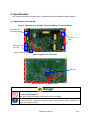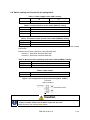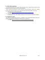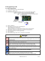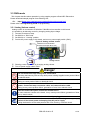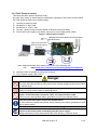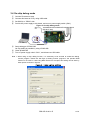
1
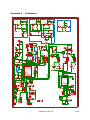
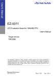
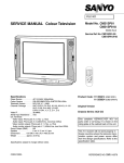
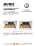
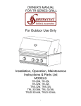
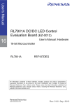
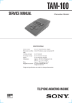
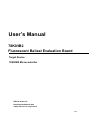
User’s Manual
78K0/IB2
Fluorescent Ballast Evaluation Board
Target Device
78K0/IB2 Microcontroller
ZBB-CE-09-0011-E
Data Published March 2009
© NEC Electronics Corporation
1/25
The information in this document is current as of March, 2009. The information is subject to change
without notice. For actual design-in, refer to the latest publications of NEC Electronics data sheets or
data books, etc., for the most up-to-date specifications of NEC Electronics products. Not all products
and/or types are available in every country. Please check with an NEC Electronics sales
representative for availability and additional information.
z No part of this document may be copied or reproduced in any form or by any means without the prior
written consent of NEC Electronics. NEC Electronics assumes no responsibility for any errors that may
appear in this document.
z NEC Electronics does not assume any liability for infringement of patents, copyrights or other
intellectual property rights of third parties by or arising from the use of NEC Electronics products listed
in this document or any other liability arising from the use of such products. No license, express,
implied or otherwise, is granted under any patents, copyrights or other intellectual property rights of
NEC Electronics or others.
z Descriptions of circuits, software and other related information in this document are provided for
illustrative purposes in semiconductor product operation and application examples. The incorporation
of these circuits, software and information in the design of a customer's equipment shall be done
under the full responsibility of the customer. NEC Electronics assumes no responsibility for any losses
incurred by customers or third parties arising from the use of these circuits, software and information.
z While NEC Electronics endeavors to enhance the quality, reliability and safety of NEC Electronics
products, customers agree and acknowledge that the possibility of defects thereof cannot be
eliminated entirely. To minimize risks of damage to property or injury (including death) to persons
arising from defects in NEC Electronics products, customers must incorporate sufficient safety
measures in their design, such as redundancy, fire-containment and anti-failure features.
z NEC Electronics products are classified into the following three quality grades: "Standard", "Special“
and "Specific".
The "Specific" quality grade applies only to NEC Electronics products developed based on a
customer-designated "quality assurance program" for a specific application. The recommended
applications of an NEC Electronics product depend on its quality grade, as indicated below.
Customers must check the quality grade of each N EC Electronics product before using it in a
particular application.
“Standard”: Computers, office equipment, communications equipment, test and measurement
equipment, audio and visual equipment, home electronic appliances, machine tools,
personal electronic equipment and industrial robots.
“Special”: Transportation equipment (automobiles, trains, ships, etc.), traffic control systems,
anti-disaster systems, anti-crime systems, safety equipment and medical equipment (not
specifically designed for life support).
“Specific”: Aircraft, aerospace equipment, submersible repeaters, nuclear reactor control systems,
life support systems and medical equipment for life support, etc.
z
The quality grade of NEC Electronics products is "Standard" unless otherwise expressly specified in
NEC Electronics data sheets or data books, etc. If customers wish to use NEC Electronics products in
applications not intended by NEC Electronics, they must contact an NEC Electronics sales
representative in advance to determine NEC Electronics' willingness to support a given application.
z
(Note)
(1)”NEC Electronics” as used in this statement means NEC Electronics C orporation and also includes
its majority-owned subsidiaries.
(2)"NEC Electronics products" means any product developed or manufactured by or for NEC
Electronics (as defined above).
ZBB-CE-09-0011-E
2/25
Safety Precautions
This document explains matters to be noted for safe use of this evaluation board. Be sure to
read this document before using this evaluation board.
•
•
Be sure to observe all dangers, warnings, cautions, and other instructions contained
herein when using this evaluation board.
This document should be kept handy at all times for ready reference.
Symbols used
This document used the following symbols for matters to be observed for the safe use of the
unit.
The symbols are followed by a brief explanation of the possible extent of problems which may
occur if the notices are not observed.
Danger
The user may suffer death or serious injury and it’s
risk is high if the warning is not observed.
Warning
The user may suffer death or serious injury if the
warning is not observed.
Caution
Human injury or property damage may occur if the
caution is not observed.
The following symbols express matters which are prohibited in order to prevent injury or accident.
General prohibition
Do not touch
Do not disassemble
The action mentioned
Touching the
Disassembly may
is prohibited.
specified location
cause a problem such
may cause injury.
as electrical shock or
product failure.
Keep away from
Flammable
Do not touch with
A nearby flame may
water
wet hands
cause the unit to
Use near water poses
Touching with wet
catch fire.
the risk of electrical
hands may cause
shock or product
electric shock or
failure if moisture were
product failure.
to contact the unit.
The following symbols are used for cautions to prevent product failure and accidents.
Caution Hot
General caution
Human injury by high temperature may
Unspecified general cautions.
occur.
The following symbols are used for instructions to prevent product failure and accidents.
Compulsory action based on
an instruction for the user.
Instruction to unplug
from AC power supply.
ZBB-CE-09-0011-E
3/25
Warnings
Danger
Do not use this board in the purpose except the evaluation of MCU.
This board does not take safety measures or anti-EMI measures required for lighting
equipment.
Do not touch to the high voltage area of the board.
Touching the board by tools or body while power is being supplied cause product failure
or electric shock.
Do not touch with wet hands.
Doing so cause product failure or electrical shock.
Do not use or store this board in any of the following locations.
- Environments with copious water, humidity, steam, dust, fumes, etc.
- Environments where static electricity or electrical noise is readily generated.
Such influences can lead to electric shock or product failure.
- Use glove to protect electric shock.
- Limit the user of this board.
Warning
Be careful to burns.
The part of board becomes high temperature during AC power is connected.
Do not disassemble or modify the board.
Doing so may cause product failure, emission of smoke, fire, or electric shock.
Do not heat the board or expose it to fire, and do not short the terminals.
Doing so may cause product failure, generation of heat, fire, or rupture.
Do not drop or jolt the board.
Doing so may break or damage the board, causing fire or electric shock.
Use AC power supply in the range of AC100[V]~240[V](50[Hz]/60[Hz]).
Using AC power supply out of this range may cause product failure, generation of heat,
fire, or electric shock.
Do not plug in or unplug a connector or cable with power applied to the board.
Doing so may cause product failure, generation of heat, fire or rupture.
Do not turn on power switch in insufficient state of cable connection such as AC
power, fluorescent lamp connection cable, and communication cable.
Doing so may cause product failure, generation of heat, fire or electric shock.
Do not carry this board with connecting any cable.
Doing so may cause damage of cable and cause product failure, generation of heat, fire
or electric shock.
Use AC power supply cable and plug adapted to safety standard of each country
with more than 5A rating.
Using non-adopt cable or plug cause product failure, generation of heat, fire or electric
shock.
ZBB-CE-09-0011-E
4/25
Warning
Use this board with spacer and on the isolated bench.
In case conductor contact to the board, it may cause product failure, generation of heat,
fire or electric shock.
Confirm the outlet is near this board and easily unplugged.
If smoke or an abnormal smell or sound is emitted, or heating occurs, promptly
switch off the board power and unplug from AC power supply.
Using the board in such a state poses a risk of fire, burning, or electric shock.
Cautions
Caution
To prevent static electricity damage, guard against energizing when touching
metal parts such as the connector.
Static electricity can cause product failure.
To prevent collisions of the board with the fluorescent lamp connection cable,
remove 1 middle cable in the 5 cables if you use the ones.
Static electricity can cause product failure.
ZBB-CE-09-0011-E
5/25
CONTENTS
CHAPTER 1
OVERVIEW
・・・・・・・・・・・・・・・・・・・・・・・・・・・・・・・・・・・・・・・・・
7
・・・・・・・・・・・・・・・・・・・・・・・・・・・・・・・・・・
9
CHAPTER 2 SPECIFICATION
・・・・・・・・・・・・・・・・・・・・・・・・・・・・・・・・・・・・・・・・・
12
SCHEMATICS ・・・・・・・・・・・・・・・・・・・・・・・・・・・・・・・・・・・・・・・・・
20
APPENDIX B BILL OF MATERIALS ・・・・・・・・・・・・・・・・・・・・・・・・・・・・・・・・・・
21
REVISION HISTORY ・・・・・・・・・・・・・・・・・・・・・・・・・・・・・・・・・・
24
CHAPTER 3
APPENDIX A
APPENDIX C
OPERATION
ZBB-CE-09-0011-E
6/25
1. Overview
78K0/IB2 Fluorescent Ballast Evaluation Board is an evaluation kit for fluorescent ballast control
by using 78K0/IB2 microcontroller.
This board can operate by AC100[V]~240[V](50[Hz]/60[Hz]) power supply.
78K0/IB2 controls PFC, Inverter which is required for fluorescent ballast control.
When connecting with Lighting Communication Master Evaluation Board(EZ-0008), it can be
controlled to dim with DALI protocol or IR remote.
Figure 1.
System Outline
AC100V~240V
Lamp
EZ-0008
Host PC
Programming/OCD
This board
(EZ-BLST-003)
1.1 Feature
•
•
•
PFC control and Inverter control by 78K0/IB2 microcontroller
PFC control by PWM timer interlocked with internal comparator
Half-Bridge inverter control output with dead-time
Support input voltage range : AC100[V]~240[V](50[Hz]/60[Hz])
Buzzer output
Up to 3 kind of control interface supported
DALI protocol communication interface
IR remote signal receive interface
Analog volume control interface
Programming / On-chip debug supported
ZBB-CE-09-0011-E
7/25
1.2 Operation Mode
•
•
•
RUN mode
Three control interfaces are offered on this board.
DALI protocol control interface
IR remote signal receive interface
Analog volume control interface
Programming mode
Flash programming through the USB interface
On-chip debug mode
On-chip debug through the USB interface.
1.3 Related product information
As for the information of related products for this board, please refer NEC Electronics Web site.
URL http://www.necel.com/micro/en/solution/lighting/index.html
ZBB-CE-09-0011-E
8/25
2. Specification
This chapter described the specification of 78K0/IB2 Fluorescent Ballast Evaluation Board.
2.1 Appearance of the board
Figure 2. Appearance of 78K0/IB2 Fluorescent Ballast Evaluation Board
Connector for
AC power supply
Connector for
Lamp
Connector
for DALI
USB connector
Surface appearance (TOP View)
78K0/IB2
Surface appearance (Bottom view)
Danger
Do not touch the area enclosed with RED line because of high voltage while
power is being supplied.
This area is also indicated by white heavy line on the board.
Use this board with spacer and on the isolated bench.
In case conductor contact to the board, it may cause product failure, generation of
heat, fire or electric shock.
ZBB-CE-09-0011-E
9/25
2.2 Detail specification
Board name
: EZ-BLST-003
Power supply
: AC100[V]~240[V](50[Hz]/60[Hz])
Microcontroller
: 78K0/IB2 (UPD78F0756MC-CAB-AX)
PFC control circuit (controlled by 78K0/IB2)
Half-bridge inverter control circuit (controlled by 78K0/IB2)
USB interface (for programming / On-chip debug)
DALI interface circuit
IR remote signal receive circuit
Analog volume
Buzzer output circuit
LED output circuit
2.3 Components which need to prepare by yourself
Power supply plug and cable : please prepare following components
Rated current
: more than 5[A]
Plug
: match to the specification for each country
Lamp and socket
Lamp
: Type: FHT42 (Compact fluorescent lamp) x 2
Socket
: Type: GX24q-4 x 2
Warning
Use power supply plug and cable with more than 5[A] current rating, and adapted to safety
standard of each country.
Using non-adopt cable or plug cause product failure, generation of heat, fire or electric
shock.
Please refer Appendix A for circuit diagram of 78K0/IB2 Fluorescent Ballast Evaluation Board
ZBB-CE-09-0011-E
10/25
2.4 Switch setting and Connector pin assignment
SW1
Table 1. Power supply switch (SW1) setting
ON
OFF
Power supply ON
Power supply OFF
Table 2. Control interface select switch (SW401) setting
Position
Control mode
1.Analog
Analog volume control
2.IR
IR remote receive control
3.DALI
DALI protocol control
Table 3. IR remote control channel select switch(SW402) setting
Position
IR remote control channel
“CH1” side Channel 1
“CH2” side Channel 2
Sample program provided from NEC Electronics is using “NEC format” with custom
code:0000h.
Receive data for each channel is using following data.
Channel 1 : Data=5Ah, Reverse Data=A5h
Channel 2 : Data=DAh, Reverse Data=25h
Table 4. Microcontroller operation mode select switch (SW501) setting
Position
MCU operation mode
“RUN” side
Run mode
“PROG” side Programming mode / On-chip debug mode
SW501
Table 5. Other switch
Description
Reset switch
Figure 3. Pin assignment of Lamp connector(CN101, CN201)
Connector
(CN101,CN201)
Fluorescent Lamp
Caution
To prevent collisions of the board with the fluorescent lamp connection cable,
remove 1 middle cable in the 5 cables if you use the ones.
Static electricity can cause product failure.
ZBB-CE-09-0011-E
11/25
3. Operation
3.1 Before using
3.1.1 Driver Installation
Install driver when connecting this board to PC by using USB cable for the first time.
① Download driver from following URL.
URL http://www.necel.com/micro/en/solution/lighting/download.html
② When connecting this board to PC by using USB cable, ”Found New Hardware Wizard”
dialog box is displayed.
Select ”Yes, now and every time I connect a device”, and click [Next].
③ Select ”Install from a list or specific location (Advanced)”, and clock [Next].
④ Select “Include this location in the search” and then click [Browse]
Specify the folder to which download files are saved, and click [Next]
⑤ Installation starts
Click [Continue Anyway] in case “Hardware Installation” dialog is displayed.
⑥ Click [Finish]. Installation is complete.
3.1.2 Programmer Installation
Please install the programmer for 78K0/IB2 flash programming.
① Download programming software “WriteEZ3” and related parameter file from following URL.
URL http://www.necel.com/micro/en/solution/lighting/download.html
② Decompress the downloaded file.
3.1.3 On-chip debugger and compiler Installation
Please install On-chip debugger and compiler if on-chip debug mode of this board is required to
be used.
① Download integrated debugger “ID78K0-QB”, NEC Electronics development tools
“PM+”,”RA78K0”, “CC78K0”, and device file for the target device 78K0/IB2 microcontroller.
URL http://www.necel.com/micro/en/solution/lighting/download.html
② Install “RA78K0”. Project manager “PM+” will be installed automatically.
③ Install “CC78K0”
④ Install device file
⑤ Install “ID78K0-QB”
ZBB-CE-09-0011-E
12/25
3.1.4 DALI GUI Installation
To control this board by DALI protocol, NEC Electronics offers “Lighting communication master
evaluation board (EZ-0008)” and GUI for easy evaluation.
About “Lighting communication master evaluation board (EZ-0008)”, please refer “Lighting
Communication Master Evaluation Board (EZ-0008) Quick Start Guide (ZED-CE-09-0018).
① Download DALI GUI from following URL.
URL http://www.necel.com/micro/en/solution/lighting/download.html
② Install DALI GUI
For detail, please refer “DALI master controller GUI User’s Manual (U19607EJ1V1UM00)”
3.1.5 Sample Program
NEC Electronics offers sample program of 78K0/IB2 to control Fluorescent ballast by this board.
Please download sample program from following URL for reference.
URL http://www.necel.com/micro/en/solution/lighting/download.html
ZBB-CE-09-0011-E
13/25
3.2 Programming mode
3.2.1 Start Programming
①
②
③
Connect this board to PC by using USB cable.
Set SW501 to “PROG” side.
Provide AC power supply to this board, and turn on power supply switch (SW1).
Figure 4. Connection when programming to 78K0/IB2
78K0/IB2 Fluorescent Ballast Evaluation board
(EZ-BLST-003)
Host PC
④
⑤
⑥
⑦
⑧
⑨
USB calbe
Start up “WriteEZ3”
Click [Setup] to open the device setup dialog box.
Select parameter file 78F0756.prm
Specify the COM port for communication between host PC and this board.
Click [Load] to select the hex file which is expected to be programmed.
Click [Autoprocedure] to do flash programming.
Close “WriteEZ3”
Turn off power supply switch “SW1”, and disconnect USB cable.
Danger
Do not touch to the high voltage area of the board.
Touching the board by tools or body while power is being supplied cause product failure
or electric shock.
Do not touch with wet hands.
Doing so cause product failure or electrical shock.
Do not turn on power switch in insufficient state of cable connection such as AC
power, fluorescent lamp connection cable, and communication cable.
Doing so may cause product failure, generation of heat, fire or electric shock.
Use this board with spacer and on the isolated bench.
In case conductor contact to the board, it may cause product failure, generation of heat,
fire or electric shock.
Confirm the outlet is near this board and easily unplugged.
If smoke or an abnormal smell or sound is emitted, or heating occurs, promptly
switch off the board power and unplug from AC power supply.
Using the board in such a state poses a risk of fire, burning, or electric shock.
ZBB-CE-09-0011-E
14/25
3.3 RUN mode
This chapter describe about operation by using sample program offered NEC Electronics.
Please download sample program from following URL.
URL: http://www.necel.com/micro/en/solution/lighting/download.html
Please refer 3.2 Programming mode for programming
3.3.1 Analog Volume control
Analog volume is connected to P70/ANI8 of 78k0/IB2 microcontroller on this board.
It is possible to do dimming control by changing analog input voltage.
① Connect Fluorescent Lamp
② Set SW501 to “RUN” side.
③ Set SW401 to “1.Analog” position
④ Provide AC power supply to this board, and turn on power supply switch (SW1).
Figure 5. Analog volume control
78K0/IB2 Fluorescent Ballast
Evaluation Board(EZ-BLST-003)
Analog Volume
⑤
⑥
Dimming control is possible by changing analog volume.
Turn off power supply switch “SW1”.
Danger
Do not touch to the high voltage area of the board.
Touching the board by tools or body while power is being supplied cause product failure
or electric shock.
Do not touch with wet hands.
Doing so cause product failure or electrical shock.
Do not turn on power switch in insufficient state of cable connection such as AC
power, fluorescent lamp connection cable, and communication cable.
Doing so may cause product failure, generation of heat, fire or electric shock.
Use this board with spacer and on the isolated bench.
In case conductor contact to the board, it may cause product failure, generation of heat,
fire or electric shock.
Confirm the outlet is near this board and easily unplugged.
If smoke or an abnormal smell or sound is emitted, or heating occurs, promptly
switch off the board power and unplug from AC power supply.
Using the board in such a state poses a risk of fire, burning, or electric shock.
ZBB-CE-09-0011-E
15/25
3.3.2 IR Remote control
IR remote receive signal is connected to P00/TI000/INTP0 of 78k0/IB2 microcontroller on this
board. By using pulse width measurement function of 16bit timer/event counter00, it is possible
to receive IR remote signal and do dimming control.
① Connect Fluorescent Lamp
② Set SW501 to “RUN” side.
③ Set SW401 to “2.IR” position
④ Provide AC power supply to this board, and turn on power supply switch (SW1).
Figure 6. IR Remote control
78K0/IB2 Fluorescent Ballast Evaluation Board
(EZ-BLST-003)
IR Receive
IR remote controller
Note. ”Lighting Communication Master Evaluation Board (EZ-0008)” can be used as IR
remote controller.
⑤
⑥
Dimming control is possible by IR remote controller.
Turn off power supply switch “SW1”.
Danger
Do not touch to the high voltage area of the board.
Touching the board by tools or body while power is being supplied cause product failure
or electric shock.
Do not touch with wet hands.
Doing so cause product failure or electrical shock.
Do not turn on power switch in insufficient state of cable connection such as AC
power, fluorescent lamp connection cable, and communication cable.
Doing so may cause product failure, generation of heat, fire or electric shock.
Use this board with spacer and on the isolated bench.
In case conductor contact to the board, it may cause product failure, generation of heat,
fire or electric shock.
Confirm the outlet is near this board and easily unplugged.
If smoke or an abnormal smell or sound is emitted, or heating occurs, promptly
switch off the board power and unplug from AC power supply.
Using the board in such a state poses a risk of fire, burning, or electric shock.
ZBB-CE-09-0011-E
16/25
3.3.3 DALI Protocol control
This board has DALI protocol interface circuit.
By using “DALI mode” of Serial Interface UART6/DALI peripheral, DALI slave communication
via TxD6, RxD6 terminal can be realized easily.
① Connect Fluorescent Lamp
② Set SW501 to “RUN” side.
③ Set SW401 to “3.DALI” side.
④ Connect “Lighting Communication Master Evaluation Board (EZ-0008)”.
⑤ Provide AC power supply to this board, and turn on power supply switch (SW1).
Figure 7. DALI Protocol control
78K0/IB2 Fluorescent Ballast Evaluation Board
(EZ-BLST-003)
Lighting Communication
Master Evaluation Board
(EZ-0008)
Host PC
Note. Please download ”DALI master control GUI” from following URL.
http://www.necel.com/micro/en/solution/lighting/download.html
URL:
⑥
⑦
Dimming control is possible by using DALI protocol.
Turn off power supply switch “SW1”.
Danger
Do not touch to the high voltage area of the board.
Touching the board by tools or body while power is being supplied cause product failure
or electric shock.
Do not touch with wet hands.
Doing so cause product failure or electrical shock.
Do not turn on power switch in insufficient state of cable connection such as AC
power, fluorescent lamp connection cable, and communication cable.
Doing so may cause product failure, generation of heat, fire or electric shock.
Use this board with spacer and on the isolated bench.
In case conductor contact to the board, it may cause product failure, generation of heat,
fire or electric shock.
Confirm the outlet is near this board and easily unplugged.
If smoke or an abnormal smell or sound is emitted, or heating occurs, promptly
switch off the board power and unplug from AC power supply.
Using the board in such a state poses a risk of fire, burning, or electric shock.
ZBB-CE-09-0011-E
17/25
3.4 On-chip debug mode
①
②
③
④
Connect Fluorescent Lamp
Connect this board to PC by using USB cable.
Set SW501 to “PROG” side.
Provide AC power supply to this board, and turn on power supply switch (SW1).
Figure 8. On-chip debug mode
78K0/IB2Fluorescent Ballast Evaluation Board
(EZ-BLST-003)
Host PC
⑤
⑥
⑦
USB cable
Setup debugger “ID78K0-QB”
On-chip debug is possible by using ID78K0-QB
Close ID78K0-QB
Turn off power supply switch “SW1”, and disconnect USB cable.
Note 1. When using on-chip debug function, it is necessary to be secured to embed the debug
monitor program. Please set 256 byte as debug monitor program if the pseudo RRM
function is not used. In case using NEC Electronics Compiler, this setting can be done by
linker option as shown in figure 9.
Figure 9. Linker option setting
ZBB-CE-09-0011-E
18/25
Note 2. When using on-chip debug function, please be care for the point and timing of step
execution or break setting. If the program execution for PFC control or half-bridge control is
stopped, it may cause product failure, generation of heat, fire.
Do not use “peripheral break” function especially for peripherals using for PFC control and
half-bridge control.
Danger
Do not touch to the high voltage area of the board.
Touching the board by tools or body while power is being supplied cause product failure
or electric shock.
Do not touch with wet hands.
Doing so cause product failure or electrical shock.
Do not turn on power switch in insufficient state of cable connection such as AC
power, fluorescent lamp connection cable, and communication cable.
Doing so may cause product failure, generation of heat, fire or electric shock.
Use this board with spacer and on the isolated bench.
In case conductor contact to the board, it may cause product failure, generation of heat,
fire or electric shock.
Confirm the outlet is near this board and easily unplugged.
If smoke or an abnormal smell or sound is emitted, or heating occurs, promptly
switch off the board power and unplug from AC power supply.
Using the board in such a state poses a risk of fire, burning, or electric shock.
ZBB-CE-09-0011-E
19/25
8
7
6
5
4
3
2
1
A
R402
33K
1
2
5
4
3
2
1
A
C501
4.7u/25V
TP29
C503
0.1u
3
4
TP40
2
1
B
TP44
C515
39p
TP41
TP43
TP42
C514
39p
C504
0.47u
R505
10K
R501
10K
C
USBVDD
3
TP6
C602
1u
USB Flash Programming & OCD
C601
0.1u
D704
1SS133
R506
1K
C505
0.1u
PROG
D
RUN
SW501
Mode SW
(Slide)
R507
100K
USBVDD
30
29
28
27
26
25
24
23
22
21
20
19
18
17
16
TP7
1
2
3
4
5
6
7
8
9
10
11
12
13
14
15
R703
10K
R701
10k
T1
77-L001
TP36
TP4 TP5
R724
6.8k
TP1
R723
330k
R722
330k
D
TP35
IC501
UPD78F0730MC-CAB-AX
P30/INTP1
P10/SCK10
P01/TI010/TO00
P11/SI10
P00/TI000
P12/SO10
P120/INTP0
P13/TxD6
RESET
P14/RxD6
FLMD0
P15
P122/X2/ELCLK/OCD0B
P16/TOH1
P121/X1/OCD0A
P17/TI50/TO50
REGC
P33/TI51/TO51
VSS
EVSS
VDD
EVDD
USBREGC
P31/INTP2/OCD1A
USBP
P32/INTP3/OCD1B
USBM
P60
USBPUC
P61
R307
10K
+5V
JMP401B
R306
0
USBVDD
1
2
3
4
5
6
7
8
9
10
11
12
13
14
15
1u
C723
JMP401A
Q704
2SC2412KR
R711
10k
+5V
C711 C712
DB1
D4SB60 1u 450V1u 450V
PC302
+5V
PS2561AL-1
4
ZD301
Q301
RD2.7S-T1-A
2SC2412KR
R304
4.7
R305
11K
TP39
C301
22u
D301
1SS133
R308
0
C
C706
1000P
D703
C703 R710
1SS133 0.1u 50V 10k
R725
47k
R709
47k
Y701
CMR309T-16.000MABJ-UT
R303
3.3K
R302
330
PC301
PS2561AL-1
3. DALI
2. IR
1. Analog
Dimming Mode SW
L501
BLM41PG750S
R504
27
C702
0.33u 250VAC
C704
1000P
C705
LF1
LF2 1000P
SS24H
SU10VD
NTC0
NTPAJ100LDKB0 D702
D1N60
SW401
R301
1.2K
2
1
+5V
+5V
R503
27
R502
1.5K
U501
74VHC125
R414
2.2k
CN501
UX60A-MB-5ST
USBVDD
GND
ID
DP
DM
VBUS
C502
0.1u
LED2
+5V
Power Indicator
DALI Connector 2
CN302
ML-800S1V X2
B
C701
0.33u 250VAC
MOV0
ERZV09D511
SW1
DB2
CN301
S1NBC60
ML-800S1V X2
1
2
F1
3.0A
DALI Connector 1
R403
33K
Power Supply
CN701
B2P3-VH
1
2
8
9
S3
S4
S1
S2
ZBB-CE-09-0011-E
6
7
Q705
2SC2412KR
TP23
+5V
A
TP19
TP2
TP9
C506
0.1u
USBVDD
R508
100K
USBVDD
TP8
E
R416 100K
R415 100K
U502A
74VHC14
JMP501A
R514
100K
USBVDD
U502C
74VHC14
USBVDD
R513
100K
USBVDD
F
R516
330
R515
330
1
2
3
4
1
2
3
4
8
7
6
5
USBVDD
C508
0.1u
R512
330
R510
330
R404
22K
Signal
TP22
G
GND
IN
OUT
JMP401F
R762
2.2K
C401
10U 25V
VR401
100K
PC503
PS9851-2
PC502
PS9851-2
PC501
PS9851-2
8
7
6
5
1
2
3
4
8
7
6
5
C512
0.1u
+5V
G
+5V
U503B
74VHC14
R517
330
H
C513
100u
U504C
74VHC125 JMP501D
+5V
C517
0.1u
R519
1K
+5V
D501
TP38 1SS133
+5V
R406
10K
C112
2kV 4700p
CN201
B5P-VH-B
I
J
JMP501B
R523
10K
R522
1K
H
+5V
JMP501C
Reset SW
(Push)
SW502
R521
100
R410
1K
PS1440P02BT
BZ0
R409
1K
Q402
2SA1037AK
+12V
C212
2kV 4700p
C
D
IC773
UPC78M05AHF-AZ
CN101
B5P-VH-B
R408
3.3K
Q401
2SC2412KR
R518
10K
R407
10K
Lamp Detection
C211 TP32
L201
1m 400V 0.18u
GND
+5V
U504B
74VHC125
U504A
74VHC125
U503A
R520
330 74VHC14
C511
0.1u
+5V
+5V
Light-Receiving Device
for Infrared Communication
C518
0.1u
TP21
C102
1000P 2KV
TP33
R405
Volume for
Analog Dimming 10K
+5V
R413 100K
+5V
JMP401G
JMP401H
R411 100K
Q102
RJK5012DPP
JMP401I
IC401
GP1UX511QS
LED1
TP3
TP24
TP25
C
TP16
F
L101
C111 TP31
1m 400V 0.18u
L701
2200UH
TP37
H
C719
50V 100u
+12V
D709
30PUB60
ZD701
MTZJ7.5B
D708
30PUB60
C717
22U 25V
IC772
MIP0221SU
ADJ
OUT
IN
G
A
Q101
C101
RJK5012DPP 1000P 2KV
TP11
C714
450V 47u
A
D
E
Half-bridge pre-driver
TP17
SW402
JMP401J
TP30
TP26
+5V
R708
6.8K
R707
330K
R706
330K
TP34
TP20
R705
10 2W
C713
470P 1KV
CH Setting
USBVDD
F
D707
D5L60
USBVDD
R511
U502B
10K
74VHC14
USBVDD
R509
100K C516
0.1u
USBVDD
JMP401E
JMP401D
TP14
TP13
JMP401C
TP15
IC771
UPD78F0756MC-CAB-AX
30
29
28
27
26
25
24
23
22
21
20
19
18
17
16
R704
0.1 3W
Q703
RJK5012DPP
PFC pre-driver
B
ANI6/P26/CMPCOM
ANI8/P70
ANI5/P25/CMP1+
ANI7/P27
ANI4/P24/CMP0+
AVSS
P60/SCLA0/TxD6
AVREF
P61/SDAA0/RxD6
ANI0/P20/AMP0P02/SSI11/INTP5
ANI1/P21/AMPOUT/PGAIN
RESET/P125
ANI2/P22/AMP0+
P122/X2/EXCLK/TOOLD0
ANI3/P23/CMP2+
P121/X1/INTP0/TOOLC0
P00/TI000/INTP0
REGC
P01/TO00/TI010
VSS
P30/TOH1/TI51/INTP1
VDD
P31/TOX00/INTP2/TOOLC1
P37/SO11
P32/TOX01/INTP3/TOOLD1
P36/SI11
P33/TOX10
P35/SCK11
P34/TOX11/INTP4
R702
10K
E
IN
GND
OUT
1
2
3
4
5
1
2
3
4
5
R125
10K
R126
10K
R123
4.7K
I
Q110
2SC2412KR
C775
25V 47u
TP12 +5V
I
A
R119
10K
R713
10K
R117
51
R109
1K
J
J
I
Q108
2SC2412KR
R422
100k
R421
100k
D105
1SS133
R424
330k
R423
330k
+5V
R719
220
R721
6.8K
GND
R115
6.8K
Q106
2SA1037AK
R111
200
Q105
2SC2412KR
R108
6.8K
Q104
2SA1037AK
R105
200
Q103
2SC2412KR
C220
0.1u
K
ZD201
MTZJ4.7B
B
E
H
D104
1SS133
G
F
D103
1SS133
Half-bridge pre-driver
R720
10
Q707
2SA1037AK
D711
1SS133
PFC pre-driver
Lamp Detection
R114
20
R113
430
R112
6.8K
R110
24K
C105
C470p
R107
20
C103
470p
K
Q706
2SC2412KR
GND
+12V
R104
2.4K
R106
10K 2W
R103
2.4K
R718
220
R717
220
R716
4.7K
Q708
2SC2412KR
D102
EP04RA60
R102
5.1K 2W
R715
10K
Q709
2SC2412KR
R714
4.7K
Q107
IRFR430APbF
Q109
2SC2412KR
R121
4.7K
C104
0.47u
R101
D101
EP04RA60 10
R120
10K
D106
1SS133
R124
10K
+12V
R712
10K
D710
1SS133
J
8
7
6
5
4
3
2
1
Appendix A.
Schematics
20/25
Appendix B. Bill of Materials
Table B. Bill of Materials (1/3)
Part
IC
IC
IC
PC
PC
PC
PC
PC
ZD
LF
LF
BZ
C
C
C
C
C
C
C
C
C
C
C
C
C
C
C
C
C
C
C
C
C
C
C
C
C
C
C
C
C
C
C
C
C
C
C
C
C
C
C
C
C
C
C
CN
CN
CN
CN
CN
CN
D
D
D
D
D
D
D
D
D
D
D
D
D
D
D
D
DB
DB
F
F
IC
IC
Number
501
771
773
301
302
501
502
503
301
1
2
0
101
102
103
104
105
111
112
211
212
220
301
401
501
502
503
504
505
506
508
511
512
513
514
515
516
517
518
601
602
701
702
703
704
705
706
711
712
713
714
717
719
723
775
101
201
301
302
501
701
101
102
103
104
105
106
301
501
702
703
704
707
708
709
710
711
1
2
1
1
772
401
Product Name and Specifications
UPD78F0730MC-CAB-AX
UPD78F0756MC-CAB-AX
UPC78M05AHF-AZ
PS2561AL-1
PS2561AL-1
PS9851-2
PS9851-2
PS9851-2
RD2.7S-T1-A
SU10VD-20010
SS24H-R20045-CH
PS1440P02BT
2KV 1000p
2KV 1000p
50V 470p
25V 0.47u
50V 470p
400V 0.18u
4700p 2KV
400V 0.18u
4700p 2kV
50V 0.1u
25V 22u
25V 10u
25V 4.7u
50V 0.1u
50V 0.1u
25V 0.47u
50V 0.1u
50V 0.1u
50V 0.1u
50V 0.1u
50V 0.1u
10V 100u
50V 39p
50V 39p
50V 0.1u
50V 0.1u
50V 0.1u
50V 0.1u
10V 1u
250VAC 0.33u
250VAC 0.33u
50V 0.1u
2kV 1000p
2kV 1000p
2kV 1000p
450V 1u
450V 1u
1KV 470p
450V 47u
25V 22u
50V 100u
10V 1u
25V 47u
B5P-VH (LF)(SN)
B5P-VH (LF)(SN)
ML-800-S1V-2P
ML-800-S1V-2P
UX60A-MB-5ST
B2P3-VH (LF)(SN)
EP04RA60
EP04RA60
1SS133
1SS133
1SS133
1SS133
1SS133
1SS133
D1N60 5060
1SS133
1SS133
D5L60 7000
30PUB60
30PUB60
1SS133
1SS133
D4SB60 L 7000
S1NBC60-7101
3.0A
F-105
MIP0221SU
GP1UX511QS 38KHz
Function
Microcontroller
Microcontroller
3-pin regulator
Photocoupler
Photocoupler
Photocoupler
Photocoupler
Photocoupler
Zener diode
AC 250 V 2 A line filter
AC 250 V 2 A line filter
Buzzer
Ceramic capacitor
Ceramic capacitor
Monolithic ceramic capacitor
Monolithic ceramic capacitor
Monolithic ceramic capacitor
Film capacitor
Film capacitor
Film capacitor
Film capacitor
Monolithic ceramic capacitor
Electrolytic capacitor
Electrolytic capacitor
Electrolytic capacitor
Monolithic ceramic capacitor
Monolithic ceramic capacitor
Monolithic ceramic capacitor
Monolithic ceramic capacitor
Monolithic ceramic capacitor
Monolithic ceramic capacitor
Monolithic ceramic capacitor
Monolithic ceramic capacitor
Electrolytic capacitor
Monolithic ceramic capacitor
Monolithic ceramic capacitor
Monolithic ceramic capacitor
Monolithic ceramic capacitor
Monolithic ceramic capacitor
Monolithic ceramic capacitor
Monolithic ceramic capacitor
Film capacitor
Film capacitor
Monolithic ceramic capacitor
Ceramic capacitor
Ceramic capacitor
Ceramic capacitor
Film capacitor
Film capacitor
Ceramic capacitor
Electrolytic capacitor
Electrolytic capacitor
Electrolytic capacitor
Monolithic ceramic capacitor
Electrolytic capacitor
Connector
Connector
Connector
Connector
Connector
Connector
FRD
FRD
Diode
Diode
Diode
Diode
Diode
Diode
Diode
Diode
Diode
FRD
FRD
FRD
Diode
Diode
D bridge (AC)
D bridge
Glass tube fuse
Fuse holder
IPD
Remote light receiving unit
Manufacturer
NEC Electronics Corporation
NEC Electronics Corporation
NEC Electronics Corporation
NEC Electronics Corporation
NEC Electronics Corporation
NEC Electronics Corporation
NEC Electronics Corporation
NEC Electronics Corporation
NEC Electronics Corporation
NEC TOKIN Corporation
NEC TOKIN Corporation
TDK Corporation
Murata Manufacturing Co., Ltd.
Murata Manufacturing Co., Ltd.
Murata Manufacturing Co., Ltd.
Murata Manufacturing Co., Ltd.
Murata Manufacturing Co., Ltd.
Panasonic Corporation
Nippon Chemi-Con Corporation
Panasonic Corporation
Nippon Chemi-Con Corporation
Murata Manufacturing Co., Ltd.
NICHICON CORPORATION
NICHICON CORPORATION
NICHICON CORPORATION
Murata Manufacturing Co., Ltd.
Murata Manufacturing Co., Ltd.
Murata Manufacturing Co., Ltd.
Murata Manufacturing Co., Ltd.
Murata Manufacturing Co., Ltd.
Murata Manufacturing Co., Ltd.
Murata Manufacturing Co., Ltd.
Murata Manufacturing Co., Ltd.
NICHICON CORPORATION
Murata Manufacturing Co., Ltd.
Murata Manufacturing Co., Ltd.
Murata Manufacturing Co., Ltd.
Murata Manufacturing Co., Ltd.
Murata Manufacturing Co., Ltd.
Murata Manufacturing Co., Ltd.
Murata Manufacturing Co., Ltd.
NISSEI ELECTRIC CO., LTD.
NISSEI ELECTRIC CO., LTD.
Murata Manufacturing Co., Ltd.
Murata Manufacturing Co., Ltd.
Murata Manufacturing Co., Ltd.
Murata Manufacturing Co., Ltd.
Rubycon Corporation
Rubycon Corporation
Murata Manufacturing Co., Ltd.
Rubycon Corporation
NICHICON CORPORATION
NICHICON CORPORATION
Murata Manufacturing Co., Ltd.
NICHICON CORPORATION
J.S.T. Mfg. Co., Ltd.
J.S.T. Mfg. Co., Ltd.
SATO PARTS CO., LTD.
SATO PARTS CO., LTD.
HIROSE ELECTRIC CO., LTD.
J.S.T. Mfg. Co., Ltd.
Nihon Inter Electronics Corporation
Nihon Inter Electronics Corporation
ROHM Co., Ltd.
ROHM Co., Ltd.
ROHM Co., Ltd.
ROHM Co., Ltd.
ROHM Co., Ltd.
ROHM Co., Ltd.
Shindengen Electric Manufacturing Co., Ltd.
ROHM Co., Ltd.
ROHM Co., Ltd.
Shindengen Electric Manufacturing Co., Ltd.
Nihon Inter Electronics Corporation
Nihon Inter Electronics Corporation
ROHM Co., Ltd.
ROHM Co., Ltd.
Shindengen Electric Manufacturing Co., Ltd.
Shindengen Electric Manufacturing Co., Ltd.
YOUBON Corporation
SATO PARTS CO., LTD.
Panasonic Corporation
Sharp Corporation
ZBB-CE-09-0011-E
Manufacturer Product Name
UPD78F0730MC-CAB-AX
UPD78F0756MC-CAB-AX
UPC78M05AHF-AZ
PS2561AL-1
PS2561AL-1
PS9851-2
PS9851-2
PS9851-2
RD2.7S-T1-A
SU10VD-20010
SS24H-R20045-CH
PS1440P02BT
DEHR33D102KB3B
DEHR33D102KB3B
GRM2162C1H471JA01D
GRM219B31E474KA88D
GRM2162C1H471JA01D
ECWF4184JB
FHACD202V472JKLDZ0
ECWF4184JB
FHACD202V472JKLDZ0
GRM21BR11H104KA01L
UPS1E220MDD
UPS1E100MDD
UPS1E4R7MDD
GRM21BR11H104KA01L
GRM21BR11H104KA01L
GRM219B31E474KA88D
GRM21BR11H104KA01L
GRM21BR11H104KA01L
GRM21BR11H104KA01L
GRM21BR11H104KA01L
GRM21BR11H104KA01L
UPS1A101MDD
GRM2162C1H390JZ01D
GRM2162C1H390JZ01D
GRM21BR11H104KA01L
GRM21BR11H104KA01L
GRM21BR11H104KA01L
GRM21BR11H104KA01L
GRM216B11A105KA01
MMDF 0250 K 334 0000 0150
MMDF 0250 K 334 0000 0150
GRM21BR11H104KA01L
DEHR33D102KB3B
DEHR33D102KB3B
DEHR33D102KB3B
450MMK105K
450MMK105K
DEHR33A332KA3B
450BXA47MCC(18×31.5)
UPS1E220MDD
UPS1H101MPD
GRM216B11A105KA01
UPS1E470MPDDD
B5P-VH (LF)(SN)
B5P-VH (LF)(SN)
ML-800-S1V-2P
ML-800-S1V-2P
UX60A-MB-5ST
B2P3-VH (LF)(SN)
EP04RA60
EP04RA60
1SS133
1SS133
1SS133
1SS133
1SS133
1SS133
D1N60 5060
1SS133
1SS133
D5L60 7000
30PUB60
30PUB60
1SS133
1SS133
D4SB60 L 7000
S1NBC60-7101
2MF-3
F-105
MIP0221SU
GP1UX511QS 38KHz
21/25
Table B. Bill of Materials (2/3)
Part
JMP
JMP
JMP
JMP
JMP
JMP
JMP
JMP
JMP
JMP
JMP
JMP
JMP
JMP
L
L
L
L
LED
LED
MOV
NTC
Q
Q
Q
Q
Q
Q
Q
Q
Q
Q
Q
Q
Q
Q
Q
Q
Q
Q
Q
Q
R
R
R
R
R
R
R
R
R
R
R
R
R
R
R
R
R
R
R
R
R
R
R
R
R
R
R
R
R
R
R
R
R
R
R
R
R
R
R
R
R
R
R
R
R
R
R
R
R
R
R
Number
401A
401B
401C
401D
401E
401F
401G
401H
401I
401J
501A
501B
501C
501D
101
201
501
701
1
2
0
0
101
102
103
104
105
106
107
108
109
110
301
401
402
703
704
705
706
707
708
709
101
102
103
104
105
106
107
108
109
110
111
112
113
114
115
117
119
120
121
123
124
125
126
301
302
303
304
305
306
307
308
402
403
404
405
406
407
408
409
410
411
413
414
415
416
421
422
423
424
501
502
Product Name and Specifications
DSP02-002-431G
DSP02-002-431G
DSP02-002-431G
DSP02-002-431G
DSP02-002-431G
DSP02-002-431G
DSP02-002-431G
DSP02-002-431G
DSP02-002-431G
DSP02-002-431G
DSP02-002-431G
DSP02-002-431G
DSP02-002-431G
DSP02-002-431G
77-L002
77-L002
BLM41PG750SN1L
2200uH
SLR332VR3F
SLR332VR3F
ERZV09D511
NTPAJ100LDKB0
RJK5012DPP-00-T2
RJK5012DPP-00-T2
2SC2412KT146R
2SA1037AKT146R
2SC2412KT146R
2SA1037AKT146R
IRFR430APbF
2SC2412KT146R
2SC2412KT146R
2SC2412KT146R
2SC2412KT146R
2SC2412KT146R
2SA1037AKT146R
RJK5012DPP-00-T2
2SC2412KT146R
2SC2412KT146R
2SC2412KT146R
2SA1037AKT146R
2SC2412KT146R
2SC2412KT146R
10 3216
5.1K 2W
2.4K 3216
2.4K 3216
200 2125
10K 2W
20
2125
6.8K 2125
1K 2125
24K 2125
200 2125
6.8K 2125
430 2125
20 2125
6.8K 2125
51 2125
10K 2125
10K 2125
4.7K 2125
4.7K 2125
10K 2125
10K 2125
10K 2125
1.2K 2125
330 2125
3.3k 2125
4.7 2125
11k 2125
0
2125
10K 2125
0
2125
33K 2125
33K 2125
22K 2125
10K 2125
10K 2125
10K 2125
3.3K 2125
1K 2125
1K 2125
100k 2125
100k 2125
2.2k 2125
100k 2125
100k 2125
100k 2125
100k 2125
330k 2125
330k 2125
10k 2125
1.5k 2125
Function
Short plug
Short plug
Short plug
Short plug
Short plug
Short plug
Short plug
Short plug
Short plug
Short plug
Short plug
Short plug
Short plug
Short plug
Inductor 1mH
Inductor 1mH
Chip Inductor
Inductor
LED
LED
Absorber
NTC thermistor
Power MOSFET
Power MOSFET
NPN transistor
PNP transistor
NPN transistor
PNP transistor
Power MOSFET
NPN transistor
NPN transistor
NPN transistor
NPN transistor
NPN transistor
PNP transistor
Power MOSFET
NPN transistor
NPN transistor
NPN transistor
PNP transistor
NPN transistor
NPN transistor
Chip resistor
Coat insulation metal film resistor
Chip resistor
Chip resistor
Chip resistor
Coat insulation metal film resistor
Chip resistor
Chip resistor
Chip resistor
Chip resistor
Chip resistor
Chip resistor
Chip resistor
Chip resistor
Chip resistor
Chip resistor
Chip resistor
Chip resistor
Chip resistor
Chip resistor
Chip resistor
Chip resistor
Chip resistor
Chip resistor
Chip resistor
Chip resistor
Chip resistor
Chip resistor
Chip resistor
Chip resistor
Chip resistor
Chip resistor
Chip resistor
Chip resistor
Chip resistor
Chip resistor
Chip resistor
Chip resistor
Chip resistor
Chip resistor
Chip resistor
Chip resistor
Chip resistor
Chip resistor
Chip resistor
Chip resistor
Chip resistor
Chip resistor
Chip resistor
Chip resistor
Chip resistor
Manufacturer
KEL Corporation
KEL Corporation
KEL Corporation
KEL Corporation
KEL Corporation
KEL Corporation
KEL Corporation
KEL Corporation
KEL Corporation
KEL Corporation
KEL Corporation
KEL Corporation
KEL Corporation
KEL Corporation
Tashiro Densetsu Corporation
Tashiro Densetsu Corporation
Murata Manufacturing Co., Ltd.
TDK Corporation
ROHM Co., Ltd.
ROHM Co., Ltd.
Panasonic Corporation
Murata Manufacturing Co., Ltd.
Renesas Technology Corp.
Renesas Technology Corp.
ROHM Co., Ltd.
ROHM Co., Ltd.
ROHM Co., Ltd.
ROHM Co., Ltd.
Vishay Intertechnology, Inc.
ROHM Co., Ltd.
ROHM Co., Ltd.
ROHM Co., Ltd.
ROHM Co., Ltd.
ROHM Co., Ltd.
ROHM Co., Ltd.
Renesas Technology Corp.
ROHM Co., Ltd.
ROHM Co., Ltd.
ROHM Co., Ltd.
ROHM Co., Ltd.
ROHM Co., Ltd.
ROHM Co., Ltd.
KOA Corporation
KOA Corporation
KOA Corporation
KOA Corporation
KOA Corporation
KOA Corporation
KOA Corporation
KOA Corporation
KOA Corporation
KOA Corporation
KOA Corporation
KOA Corporation
KOA Corporation
KOA Corporation
KOA Corporation
KOA Corporation
KOA Corporation
KOA Corporation
KOA Corporation
KOA Corporation
KOA Corporation
KOA Corporation
KOA Corporation
KOA Corporation
KOA Corporation
KOA Corporation
KOA Corporation
KOA Corporation
KOA Corporation
KOA Corporation
KOA Corporation
KOA Corporation
KOA Corporation
KOA Corporation
KOA Corporation
KOA Corporation
KOA Corporation
KOA Corporation
KOA Corporation
KOA Corporation
KOA Corporation
KOA Corporation
KOA Corporation
KOA Corporation
KOA Corporation
KOA Corporation
KOA Corporation
KOA Corporation
KOA Corporation
KOA Corporation
KOA Corporation
ZBB-CE-09-0011-E
Manufacturer Product Name
DSP02-002-431G
DSP02-002-431G
DSP02-002-431G
DSP02-002-431G
DSP02-002-431G
DSP02-002-431G
DSP02-002-431G
DSP02-002-431G
DSP02-002-431G
DSP02-002-431G
DSP02-002-431G
DSP02-002-431G
DSP02-002-431G
DSP02-002-431G
77-L002
77-L002
BLM41PG750SN1L
TSL1112-2222JR33
SLR332VR3F
SLR332VR3F
ERZV09D511
NTPAJ100LDKB0
RJK5012DPP-00-T2
RJK5012DPP-00-T2
2SC2412KT146R
2SA1037AKT146R
2SC2412KT146R
2SA1037AKT146R
IRFR430APbF
2SC2412KT146R
2SC2412KT146R
2SC2412KT146R
2SC2412KT146R
2SC2412KT146R
2SA1037AKT146R
RJK5012DPP-00-T2
2SC2412KT146R
2SC2412KT146R
2SC2412KT146R
2SA1037AKT146R
2SC2412KT146R
2SC2412KT146R
RK73B2BTTD100G
MOS2C(T52A)512J
RK73B2BTTD242G
RK73B2BTTD242G
RK73B2ATTD201G
MOS2C(T52A)103J
RK73B2ATTD200G
RK73B2ATTD682G
RK73B2ATTD102G
RK73B2ATTD243G
RK73B2ATTD201G
RK73B2ATTD682G
RK73B2ATTD431G
RK73B2ATTD200G
RK73B2ATTD682G
RK73B2ATTD510G
RK73B2ATTD103G
RK73B2ATTD103G
RK73B2ATTD472G
RK73B2ATTD472G
RK73B2ATTD103G
RK73B2ATTD103G
RK73B2ATTD103G
RK73B2ATTD122G
RK73B2ATTD331G
RK73B2ATTD332G
RK73B2ATTD4R7G
RK73B2ATTD113G
RK73Z2ATTD
RK73B2ATTD103G
RK73Z2ATTD
RK73B2ATTD333G
RK73B2ATTD333G
RK73B2ATTD223G
RK73B2ATTD103G
RK73B2ATTD103G
RK73B2ATTD103G
RK73B2ATTD332B
RK73B2ATTD102G
RK73B2ATTD102G
RK73B2ATTD104G
RK73B2ATTD104G
RK73B2ATTD222G
RK73B2ATTD104G
RK73B2ATTD104G
RK73B2ATTD104G
RK73B2ATTD104G
RK73B2ATTD334G
RK73B2ATTD334G
RK73B2ATTD103G
RK73B2ATTD152G
22/25
Table B. Bill of Materials (3/3)
Part
R
R
R
R
R
R
R
R
R
R
R
R
R
R
R
R
R
R
R
R
R
R
R
R
R
R
R
R
R
R
R
R
R
R
R
R
R
R
R
R
R
R
R
R
R
R
R
SW
SW
SW
SW
SW
T
TP
TP
TP
TP
TP
TP
TP
TP
TP
TP
TP
TP
TP
TP
TP
TP
TP
TP
TP
TP
TP
TP
TP
TP
TP
TP
TP
TP
TP
TP
TP
TP
U
U
U
U
VR
Y
ZD
ZD
Number
503
504
505
506
507
508
509
510
511
512
513
514
515
516
517
518
519
520
521
522
523
701
702
703
704
705
706
707
708
709
710
711
712
713
714
715
716
717
718
719
720
721
722
723
724
725
762
1
401
402
501
502
1
1
2
3
4
5
6
7
11
12
13
14
15
16
17
19
20
21
22
23
24
25
26
29
30
31
32
33
34
35
36
37
38
501
502
503
504
401
701
201
701
Product Name and Specifications
27 2125
27 2125
10k 2125
1k 2125
100k 2125
100k 2125
100k 2125
330 2125
10k 2125
330 2125
100k 2125
100k 2125
330 2125
330 2125
330 2125
10k 2125
1K 2125
330 2125
100 2125
1k 2125
10K 2125
10K 2125
10K 2125
10K 2125
0.1 3W
10 2W
330K 3216
330K 3216
6.8K 2125
47k 3216
10K 2125
10K 2125
10K 2125
10K 2125
4.7K 2125
10K 2125
4.7K 2125
220 2125
220 2125
220 2125
10 2125
6.8k 2125
330k 3216
330k 3216
6.8k 2125
47k 3216
2.2k 2125
M2T-12AAP1
SSSF014800
SS-12SDP2
SS-12SDP2
SKHRAAA010
77-L001
LC-2-G -green
LC-2-G -green
LC-2-G -green
LC-2-G -green
LC-2-G -green
LC-2-G -green
LC-2-G -green
LC-2-G -black
LC-2-G -green
LC-2-G -green
LC-2-G -green
LC-2-G -green
LC-2-G -green
LC-2-G -green
LC-2-G -green
LC-2-G -green
LC-2-G -green
LC-2-G -green
LC-2-G -green
LC-2-G -green
LC-2-G -green
LC-2-G -green
LC-2-G -green
LC-2-G -green
LC-2-G -green
LC-2-G -green
LC-2-G -green
LC-2-G -green
LC-2-G -green
LC-2-G -green
LC-2-G -green
LC-2-G -green
TC74VHC125F
TC74VHC14F
TC74VHC14F
TC74VHC125F
100K
CMR309T-16.000MABJ-UT
4.7V
7.5V
Function
Chip resistor
Chip resistor
Chip resistor
Chip resistor
Chip resistor
Chip resistor
Chip resistor
Chip resistor
Chip resistor
Chip resistor
Chip resistor
Chip resistor
Chip resistor
Chip resistor
Chip resistor
Chip resistor
Chip resistor
Chip resistor
Chip resistor
Chip resistor
Chip resistor
Chip resistor
Chip resistor
Chip resistor
Coat insulation metal film resistor
Coat insulation metal film resistor
Chip resistor
Chip resistor
Chip resistor
Chip resistor
Chip resistor
Chip resistor
Chip resistor
Chip resistor
Chip resistor
Chip resistor
Chip resistor
Chip resistor
Chip resistor
Chip resistor
Chip resistor
Chip resistor
Chip resistor
Chip resistor
Chip resistor
Chip resistor
Chip resistor
Power switch
Selector switch
Slide switch
Slide switch
Tact switch
Inductor
Test pin
Test pin
Test pin
Test pin
Test pin
Test pin
Test pin
Test pin
Test pin
Test pin
Test pin
Test pin
Test pin
Test pin
Test pin
Test pin
Test pin
Test pin
Test pin
Test pin
Test pin
Test pin
Test pin
Test pin
Test pin
Test pin
Test pin
Test pin
Test pin
Test pin
Test pin
Test pin
IC
IC
IC
IC
Volume dial
Oscillator
Zener diode
Zener diode
Manufacturer
KOA Corporation
KOA Corporation
KOA Corporation
KOA Corporation
KOA Corporation
KOA Corporation
KOA Corporation
KOA Corporation
KOA Corporation
KOA Corporation
KOA Corporation
KOA Corporation
KOA Corporation
KOA Corporation
KOA Corporation
KOA Corporation
KOA Corporation
KOA Corporation
KOA Corporation
KOA Corporation
KOA Corporation
KOA Corporation
KOA Corporation
KOA Corporation
KOA Corporation
KOA Corporation
KOA Corporation
KOA Corporation
KOA Corporation
KOA Corporation
KOA Corporation
KOA Corporation
KOA Corporation
KOA Corporation
KOA Corporation
KOA Corporation
KOA Corporation
KOA Corporation
KOA Corporation
KOA Corporation
KOA Corporation
KOA Corporation
KOA Corporation
KOA Corporation
KOA Corporation
KOA Corporation
KOA Corporation
NIHON KAIHEIKI IND. CO., Ltd.
ALPS ELECTRIC CO., LTD.
NIHON KAIHEIKI IND. CO., Ltd.
NIHON KAIHEIKI IND. CO., Ltd.
ALPS ELECTRIC CO., LTD.
Tashiro Densetsu Corporation
Mac-Eight Co., Ltd.
Mac-Eight Co., Ltd.
Mac-Eight Co., Ltd.
Mac-Eight Co., Ltd.
Mac-Eight Co., Ltd.
Mac-Eight Co., Ltd.
Mac-Eight Co., Ltd.
Mac-Eight Co., Ltd.
Mac-Eight Co., Ltd.
Mac-Eight Co., Ltd.
Mac-Eight Co., Ltd.
Mac-Eight Co., Ltd.
Mac-Eight Co., Ltd.
Mac-Eight Co., Ltd.
Mac-Eight Co., Ltd.
Mac-Eight Co., Ltd.
Mac-Eight Co., Ltd.
Mac-Eight Co., Ltd.
Mac-Eight Co., Ltd.
Mac-Eight Co., Ltd.
Mac-Eight Co., Ltd.
Mac-Eight Co., Ltd.
Mac-Eight Co., Ltd.
Mac-Eight Co., Ltd.
Mac-Eight Co., Ltd.
Mac-Eight Co., Ltd.
Mac-Eight Co., Ltd.
Mac-Eight Co., Ltd.
Mac-Eight Co., Ltd.
Mac-Eight Co., Ltd.
Mac-Eight Co., Ltd.
Mac-Eight Co., Ltd.
Toshiba Semiconductor Company
Toshiba Semiconductor Company
Toshiba Semiconductor Company
Toshiba Semiconductor Company
Bourns Inc.
CITIZEN ELECTRONICS CO., LTD
ROHM Co., Ltd.
ROHM Co., Ltd.
ZBB-CE-09-0011-E
Manufacturer Product Name
RK73B2ATTD270G
RK73B2ATTD270G
RK73B2ATTD103G
RK73B2ATTD102G
RK73B2ATTD104G
RK73B2ATTD104G
RK73B2ATTD104G
RK73B2ATTD331G
RK73B2ATTD103G
RK73B2ATTD331G
RK73B2ATTD104G
RK73B2ATTD104G
RK73B2ATTD331G
RK73B2ATTD331G
RK73B2ATTD331G
RK73B2ATTD103G
RK73B2ATTD102G
RK73B2ATTD331G
RK73B2ATTD101G
RK73B2ATTD102G
RK73B2ATTD103G
RK73B2ATTD103G
RK73B2ATTD103G
RK73B2ATTD103G
MOSX3C(T52A)R10J
MOS2C(T52A)100G
RK73B2BTTD334G
RK73B2BTTD334G
RK73B2ATTD682G
RK73B2BTTD473G
RK73B2ATTD103G
RK73B2ATTD103G
RK73B2ATTD103G
RK73B2ATTD103G
RK73B2ATTD472G
RK73B2ATTD103G
RK73B2ATTD472G
RK73B2ATTD221G
RK73B2ATTD221G
RK73B2ATTD221G
RK73B2ATTD100G
RK73B2ATTD682G
RK73B2BTTD334G
RK73B2BTTD334G
RK73B2ATTD682G
RK73B2BTTD473G
RK73B2ATTD222G
M2T-12AAP1
SSSF014800
SS-12SDP2
SS-12SDP2
SKHRAAA010
77-L001
LC-2-G -green
LC-2-G -green
LC-2-G -green
LC-2-G -green
LC-2-G -green
LC-2-G -green
LC-2-G -green
LC-2-G -black
LC-2-G -green
LC-2-G -green
LC-2-G -green
LC-2-G -green
LC-2-G -green
LC-2-G -green
LC-2-G -green
LC-2-G -green
LC-2-G -green
LC-2-G -green
LC-2-G -green
LC-2-G -green
LC-2-G -green
LC-2-G -green
LC-2-G -green
LC-2-G -green
LC-2-G -green
LC-2-G -green
LC-2-G -green
LC-2-G -green
LC-2-G -green
LC-2-G -green
LC-2-G -green
LC-2-G -green
TC74VHC125F
TC74VHC14F
TC74VHC14F
TC74VHC125F
3386F-1-104TLF
CMR309T-16.000MABJ-UT
MTZJ T-77 4.7B
MTZJ T-77 7.5B
23/25
Appendix C. Revision History
Revision
Modified Points
Page
Rev.1.0
ZBB-CE-09-0011-E
24/25
For further information,
please contact:
NEC Electronics Corporation
1753, Shimonumabe, Nakahara-ku,
Kawasaki, Kanagawa 211-8668,
Japan
Tel: +81-44-435-111
http://www.necel.com/
[Technical Support]
Multipurpose Microcomputer System Division, NEC Electronics
Tel: +81-44-435-9452
Data Published March 2009
ZBB-CE-09-0011-E
25/25