1
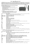
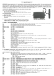
Alarm system GSM communicator
GSW1U user manual.
1. INTRODUCTION. Nowadays environment is full of sounds generated by vehicle alarm systems thus people rarely pay attention to the sound of an alarm and
alarm signal does not reach the addressee. GSW1U is a modern solution for this problem developed by “KODINIS RAKTAS”. It is a special mobile phone
specialized to send alarm messages. Like other GSM devices it must have activated SIM card and to be registered in GSM network. Communicator has a
phonebook where it is possible to save up to 3 phone numbers (PHN1, PHN2, PHN3). When the alarm system is in ARMED state and triggered, these 3
phone numbers will receive voice alarm messages and PHN1 will receive info and alarm SMS messages. For easy use and setup GSW1U has 25 voice
channel commands and 88 SMS commands. SMS commands are sent from PHN1 and this PHN1 will receive answers from GSW1U.
2. HOW TO SEND COMMAND. Commands are used to check, delete, enter phone numbers
into phonebook, set priority, change PIN code and control optional devices connected to
GSW1U relays. To send command follow these steps:
dial GSW1U phone number and make a call;
hear the GSW1U answer with a voice message about alarm system status;
still being connected with GSW1U, dial initial GSW1U PIN code (1234) using mobile or
stationary phone keypad and press ;
hear the GSW1U answer “OK”;
still being connected with GSW1U, dial command number (see Paragraph 3) using
mobile or stationary phone keypad;
dial next command number if necessary or finish a call by dialling 0
if none of the phone buttons is pressed within period of 45 seconds, the call is finished
automatically.
!
It's important: GSW1U must be prepared to accept commands:
- make sure that GSW1U incorporates SIM card with prepaid account, that PIN code
request is turned off on the SIM card, and SMS service centre number is entered;
first, make sure that all send and received SMS are erased;
- make sure that GSW1U is connected to the alarm system and power supply.
Alarm system GSM communicator GSW1U
3. THE SET OF VOICE CHANNEL COMMANDS.
0
- finish a call (when GSW1U reports about alarm and does not get confirmation 0 , it will call to all 3 phone numbers from
phonebook 3 times each);
0
- check the last alarm message or system state;
0 0
- delete the last alarm message (alarm message will be also deleted automatically after rearming GSW1U);
1 1
phone number
- save PHN1 into the 1st phonebook position;
2 2
phone number
- save PHN2 into the 2nd phonebook position;
3 3
phone number
- save PHN3 into the 3rd phonebook position;
1
- check PHN1;
2
- check PHN2;
3
- check PHN3;
1 1
- delete PHN1 from the 1st phonebook position;
2 2
- delete PHN2 from the 2nd phonebook position;
3 3
- delete PHN3 from the 3rd phonebook position;
5
- check the priority of PHN1;
5 0
- reset the priority of PHN1;
(when alarm system is triggered GSW1U will call to PHN1, PHN2 and PHN3);
5 5
- set the priority of PHN1;
(when a call reaches PHN1 and confirmation 0
from it is received by GSW1U, GSW1U will not call to PHN2 and PHN3);
6
- check the 1st relay status;
6 0
- turn OFF the 1st relay;
6 1
- turn ON the 1st relay and turn it OFF according to the 1st timer setting;
6 6
- turn ON the 1st relay;
6 6 6
- temporary switch over the 1st relay, if relay was ON it will be OFF (after 45 seconds or pressing buttons 0 , 1 ,... 9 , or
relay will
return to previous state);
9
- check the 2nd relay status;
9 0
- turn OFF the 2nd relay;
9 1
- turn ON the 2nd relay and turn it OFF according to the 2nd timer setting;
9 9
- turn ON the 2nd relay;
9 9 9
- temporary switch over the 2nd relay, if relay was ON it will be OFF (after 45 seconds or pressing buttons 0 , 1 ,... 9 , or
relay will
return to previous state).
!
It is important: telephone number must be entered with international country code. Do not add ‘+’ sign before the country code, for example,
3706528888 , PHN1, PHN2 and PHN3 - not longer than 16 digits.
1
1
4. GSW1U RESPONSE TO VOICE CHANNEL COMMANDS.
0
- will finish a call;
0
- GSW1U will say twice: “ON, OK” if armed system was not triggered, “OFF” if alarm system is disarmed, or “ALARM, ...”, if alarm
system was triggered;
0 0
- GSW1U will say: “ALARM EMPTY”;
1 1
phone number
- GSW1U will say: “PHONE NUMBER ONE” after 1 1
was dialled and “OK” after PHONE NUMBER and
was dialled;
2 2
phone number
- GSW1U will say: “PHONE NUMBER TWO” after 2 2
was dialled and “OK” after PHONE NUMBEr and
was dialled;
3 3
phone number
- GSW1U will say: “PHONE NUMBER THREE” after 3 3
was dialled and “OK” after PHONE NUMBER and
was dialled;
1
- GSW1U will say: “PHONE NUMBER ONE” and phone number in the 1st phonebook position;
2
- GSW1U will say: “PHONE NUMBER TWO” and phone number in the 2nd phonebook position;
3
- GSW1U will say: “PHONE NUMBER THREE” and phone number in the 3rd phonebook position;
Note: If phonebook position is empty GSW1U instead of phone number will say: “EMPTY”.
1 1
- GSW1U will say: “EMPTY”;
2 2
- GSW1U will say: “EMPTY”;
3 3
- GSW1U will say: “EMPTY”;
5
- GSW1U will say: “ON, NUMBER ONE” if priority set to PHN1 or “ON, NUMBER ONE, TWO, THREE”, if all 3 phone numbers have
the same priority;
5 0
- GSW1U will say: “ON, NUMBER ONE, TWO, THREE”;
5 5
- GSW1U will say: “ON, NUMBER ONE”;
6
- GSW1U will say: “RELAY 1 ON” if it is on, “RELAY 1 OFF” if it is off, or “RELAY 1 ON” and six digits of remaining duty time: “X X Y
Y Z Z” (X X - hours, Y Y - minutes, Z Z - seconds), if it is launched according to the 1st timer setting;
6 0
- GSW1U will say: “RELAY 1 OFF”;
6 1
- GSW1U will say: “RELAY 1 ON” and six digits of remaining duty time: “X X Y Y Z Z” (X X - hours, Y Y - minutes, Z Z - seconds);
6 6
- GSW1U will say: “RELAY 1 ON”;
6 6 6
- GSW1U will say: “RELAY 1 OFF”, if before dialling 6 6 6
it was on, or “RELAY 1 ON”, if it was off;
9
- GSW1U will say: “RELAY 2 ON” if it is on, “RELAY 2 OFF” if it is off, or “RELAY 2 ON” and six digits of remaining duty time: “X X Y
Y Z Z” (X X - hours, Y Y - minutes, Z Z - seconds), if it is launched according to the 2nd timer setting;
9 0
- GSW1U will say: “RELAY 2 OFF”;
9 1
- GSW1U will say: “RELAY 2 ON” and six digits of remaining duty time: “X X Y Y Z Z” (X X - hours, Y Y - minutes, Z Z - seconds);
9 9
- GSW1U will say: “RELAY 2 ON”;
9 9 9
- GSW1U will say: “RELAY 2 OFF”, if before dialling 9 9 9
it was on, or “RELAY 2 ON”, if it was off.
5. SMS COMMANDS.
For easy use and setup GSW1U has two types of SMS commands. Basic SMS commands are alternative to voice channel commands (see Paragraph 3).
There are also setup SMS commands used by installers or clients to customize GSW1U.
5.1 Sending SMS command:
- check if PHN1 is saved in GSW1U phonebook (see Paragraph 3);
- use a mobile phone with PHN1 SIM card to write SMS message;
- write a command from the list (see Pararaph 6);
- send SMS to GSW1U phone number;
6. THE SET OF SMS COMMANDS.
Notes:
1. In SMS command text both characters - capitals and minuscules are possible (for example, command A
is analogue to command a
);
2. 'Space' symbol can be entered before first command line symbol . In some cases it helps to ensure sending SMS between different
GSM networks;
3. In case GSW1U does not recognize the command (when inappropriate command or any other symbol is sent) it sends SMS with system
state (equivalent to command
0
).
6.1 Basic commands
0
- check the last alarm message or system state;
00
- delete the alarm message (alarm message will be also deleted automatically after rearming GSW1U);
11
phone number
- save PHN1 into the 1st phonebook position;
2 2 phone number
- save PHN2 into the 2nd phonebook position;
3 3 phone number
- save PHN3 into the 3rd phonebook position;
1
- check PHN1;
2
- check PHN2;
3
- check PHN3;
11
- delete PHN1 from the 1st phonebook position;
22
- delete PHN2 from the 1st phonebook position;
33
- delete PHN3 from the 1st phonebook position;
5
- check the priority of PHN1;
50
- reset the priority of PHN1 (when alarm system is triggered GSW1U will call to PHN1, PHN2 and PHN3);
55
- set the priority of PHN1 (when a call reaches PHN1 and confirmation 0
from it is received by GSW1U, GSW1U will
not call to PHN2 and PHN3);
Timers
for relays control
T
T6
XXhYYmZZs
T9
XXhYYmZZs
6
60
61
66
9
90
91
99
6.2 Setup commands
Alarming mode
A
A0
- report about 1st and 2nd relay timer interval;
- to set the 1st relay timer interval, when XX - hours, YY - minutes, ZZ - seconds;
- to set the 2nd relay timer interval, when XX - hours, YY - minutes, ZZ - seconds;
- check the 1st relay status;
- turn OFF the 1st relay;
- turn ON the 1st relay and turn it OFF according to the 1st timer setting;
- turn ON the 1st relay;
- check the 2nd relay status;
- turn OFF the 2nd relay;
- turn ON the 2nd relay and turn it OFF according to the 2nd timer setting;
- turn ON the 2nd relay;
- request for the info about pre-programmed mode of alarm signal transmission;
- when alarm system is triggered GSW1U does not call up to 3 phone numbers
send SMS to PHN1;
- when alarm system is triggered GSW1U calls up to 3 phone numbers for voice
to PHN1;
- when alarm system is triggered GSW1U does not call up to 3 phone numbers
to PHN1;
- when alarm system is triggered GSW1U calls up to 3 phone numbers for voice
A1
A2
A3
Broadcasting
for voice messages, does not
messages, does not send SMS
for voice messages, send SMS
messages, sends SMS to PHN1;
of state by SMS
B
B0
B1
B2
B3
Connection
C
- request for the info about sending SMS with system state after arming/disarming;
- when arming/disarming GSW1U does not send validation SMS;
- when arming GSW1U sends SMS to PHN1, when disarming does not send SMS;
- when disarming GSW1U sends SMS to PHN1, when arming does not send SMS;
- when arming/disarming GSW1U sends SMS to PHN1;
- request for the info whether or not GSW1U will send SMS message to PHN1 about disappearing / appearing GSM
signal;
- if GSM signal appears / disappears GSW1U does not send any messages;
- if GSM signal appears / disappears GSW1U sends SMS message to PHN1. When GSM signal disappears - “No
network !”, when GSM signal appears - “Network restored”;
C0
C1
Digest
D
Forwarding
- is equivalent to
A
and
B
commands together;
SMS
F
- request for the info about SMS messages that come not from PHN1 and have to be forwarded to PHN1;
F0
- disable forwarding SMS that come not from PHN1 to PHN1;
F1
- enable forwarding SMS that come not from PHN1 to PHN1;
Note: Maximum SMS text length is 100 symbols; in case of exceeding this length, text will be cut.
Length of pulses in CLK input
L
- request for the info about the minimal duration for pulse which goes to CLK input and still is able to turn ON the
GSW1U alarm mode;
Lj
- set the minimal duration for pulse which goes to CLK input and still is able to turn ON the GSW1U alarm mode.
Instead of “j” digits from 0 to 9 have to be entered. They mean: from 1 to 9 - respectively - the pulse length
from 10 ms to 90 ms and 0 means 100 ms;
Mode of arming state detection
M
- request for the info about controlling the GSW1U alarm mode;
M0
- GSW1U alarm mode is ON when there is ‘Low’ level in CLK input (0 - 2.5 V);
M1
- GSW1U alarm mode is ON when there is ‘High’ level in CLK input (4.5 - 12 V);
M2
- GSW1U alarm mode is ON when there are pulses in CLK input and they are not shorter than 10 ms and not
longer than 5 s (pulses can be non-periodic);
M3
- GSW1U alarm mode is ON when there are pulses in CLK input and they are not shorter than 100 ms and not
longer than 5 s.
!
It is important: commands
input.
Note:
M0
,
M1
,
M2
and
M3
will be executed by GSW1U only when +12 V voltage is attached to DAT
SMS command
M3
has to be sent when the system is in the arming mode. After getting SMS with a code, GSW1U measures the
duration of pulses and penetration in the CLK input. If pulses are not shorter than 100ms and not longer than 5 seconds, GSW1U will send
to PHN1 such SMS message: “Pulse progr. completed”, t(+)=XXXms t(-)=YYYms”, where XXX - duration of positive pulse, YYY - duration of
negative pulse. If there are pulses in CLK input but their duration is shorter than 100ms, GSW1U will send such SMS message: “Short
pulses”; if the duration of pulses is longer than 5 seconds - GSW1U will send such SMS messages: “No pulses”, in this case the meaning
of “M” keeps unchanged.
Waiting
for arming
W
Wj
- request for the info about the retention duration. After arming during this retention period GSW1U does not react
to signals in Z 1, Z 2, Z 3 and Z 4 inputs;
- setting of retention duration in seconds; here “j” - digits from 0 to 9 that mean retention duration;
Operational
reliability
To ensure correct GSW1U operation it is necessary to restart GSW1U modem few times per day (usually problems occur after prepaying GSW1U
SIM card account).
O
- request for the info about the amount of GSW1U restarts per 24 hours;
Oj
- set the amount of restarts per 24 hours. Instead of “j” digits from 0 to 9 have to be entered. They mean an
amount of system restarts per 24 hours;
Version of GSW1U
V
- request for the info about GSW1U manufacturing date and version;
Sending
!
SMS via GSW1U
X Telephone no. Text
- send SMS to phone number “Telephone no.” with a text “Text”. Phone number length - from 3 to 16 digits. Total length
of telephone number (including a sign “+” if phone number is entered with international country code) and text cannot
be longer than 108 symbols. Any symbols including
and
can be used in the text.
It is important: it is possible to send few commands in one SMS message. To send few commands, use same commands from the commands lists (see
Parapgraph 6 and 7, excluding a command X Telephone no. Text ). This SMS message must be started by
and finished by . Commands from 6
and 7 paragraphs must be changed as follows:
1. remove
in the beginning of command;
2. remove
in the end of command;
For example: N
and A 1
commands can be sent together as such command - N A 1
(command line not longer than 100 symbols);
Notes:
1. Maximum relays timers interval is 18 hours 12 minutes and 15 seconds or 65535 seconds. Time can be set on hours, minutes, seconds or only
on hours, only on minutes or only on seconds. Number of hours has to be with character h or H, minutes with character m or M, seconds with
character s or S. For example, possible commands for timer interval 1 hour 15 minutes setting:
T6 1h15m
or
T6 75M
or
T6 4500s
;
2. Initial GSW1U settings: A=1, B=0, F=0, L=0, M=0, W=0. Timers intervals - 5 seconds;
7. GSW1U RESPONSE TO INFORMATIVE SMS COMMANDS.
0
1
2
3
5
T
- GSW1U will send: “Disarmed”, “Armed OK” or “Armed xxx”, where xxx - alarm message;
- GSW1U will send: “Number 1 is: NNNNNN”, where NNNNNN is PHN1;
- GSW1U will send: “Number 2 is: NNNNNN”, where NNNNNN is PHN2;
- GSW1U will send: “Number 3 is: NNNNNN”, where NNNNNN is PHN3;
- GSW1U will send: “Phone number 1 priority off" or “Phone number 1 priority on”;
- GSW1U will send: “Timer 1 interval: XXhYYmZZs / Timer 2 interval: XXhYYmZZs”, where XX - hours, YY - minutes, ZZ seconds;
6
- GSW1U will send:
“Relay 1 ON”, if it is on;
“Relay 1 OFF” if it is off;
“Relay 1 is on, will be off after XXhYYmZZs” (XX - hours, YY - minutes, ZZ - seconds), if the 1st relay timer
is ON;
9
- GSW1U will send:
“Relay 2 ON”, if it’s on;
“Relay 2 OFF” if it’s off;
“Relay 2 is on, will be off after XXhYYmZZs” (XX - hours, YY - minutes, ZZ - seconds), if the 2nd relay
timer is ON;
A
- GSW1U will send SMS about alarming mode. Possible messages:
“A=0 (Alarm: don’t call, don’t send SMS)”;
“A=1 (Alarm: call, don’t send SMS)”;
“A=2 (Alarm: don’t call, send SMS)”;
“A=3 (Alarm: call, send SMS)”;
B
- GSW1U will send info about the mode of sending SMS with system state after arming / disarming. Possible messages:
“B=0 (Arm - don’t send SMS, disarm - don’t send SMS)”;
“B=1 (Arm - send SMS, disarm - don’t send SMS)”;
“B=2 (Arm - don’t send SMS, disarm - send SMS)”;
“B=3 (Arm - send SMS, disarm - send SMS)”;
Ñ
- GSW1U will send info about whether SMS message is sent to PHN1 when GSM signal disappears / appears. Possible
messages:
“C=0 (No network: don’t send SMS)”;
D
- GSW1U will send info about alarming mode and the mode of sending SMS with system state after arming / disarming.
in one SMS message. For example:
“A=1 (Alarm: call, don’t send SMS) / B=3 (Arm - send SMS, disarm - send SMS)”;
F
- GSW1U will send: “F=0 (SMS forwarding is off)” or “F=1 (SMS forwarding is on)”;
L
- GSW1U will send: “Min. pulse duration (M=2): XX ms”;
M
- GSW1U will send info about arming mode. Possible messages:
“M=0(Arming on CLK=0V)”;
“M=1(Arming on CLK=12V)”;
“M=2(Arming by pulse CLK)”;
“M=3(Arming by progr. pulse CLK=0V)”;
W
- GSW1U will send: “Delay after arming: Xsec.”, X - retention duration;
O
- GSW1U will send: “Modem off/on times in 24 h: ...”;
V
- GSW1U will send: “Version: V”, V - GSW1U manufacturing date and version;
X Telephone no. Text
- GSW1U will send: “X-SMS don’t sent (Telephone no. Text)”, if GSW1U cannot send SMS to indicated telephone
number.
8. THE SET OF SMS COMMANDS FOR PROGRAMMING GSW1U Z INPUTS.
GSW1U has four alarm trigger inputs Z I (I=1, 2, 3, 4). Inputs Z2, Z3, Z4 are preset to interact with sensors driving ‘Low’ level. It can be door, bonnet, luggage
compartment switches or shock sensor, etc. Input Z1 is preset to interact with sensors driving ‘High’ level. It can be the output of alarm system siren or engine
ignition signal. Z inputs are programmed by means of SMS commands as follows:
Names of Alarms
N
- request for the info about messages that are sent when all 4 zones trigger;
NI
- request for the info about a message that is sent when zone I triggers;
NI0
- assign message “Alarm..” for the input I;
NI1
- assign message “Alarm, zone 1” for the input I;
NI2
- assign message “Alarm, zone 2” for the input I;
NI3
- assign message “Alarm, zone 3” for the input I;
NI4
- assign message “Alarm, zone 4” for the input I;
NI5
- assign message “Alarm, car’s body” for the input I;
NI6
- assign message “Alarm, car’s window” for the input I;
NI7
- assign message “Alarm, car’s door” for the input I;
NI8
- assign message “Alarm, car’s trunk” for the input I;
NI9
- assign message “Alarm, car’s engine” for the input I;
Reaction
to pulse in zone input
Every Z input can be programmed in a way that alarm system will send alarm messages only when a specific length signal triggers GSW1U input. This
protects from various disturbances or wrong alarm system operations.
R
- request for the info about the length of specific pulses. When specific length pulses trigger GSW1U inputs Z 1, Z 2, Z 3, Z 4,
alarm system sends alarm messages. If pulses are shorter alarm system does not react to them;
RI
- request for the info about the shortest pulse which triggers GSW1U input I and the alarm system sends alarm messages;
RIXX
-set the length of pulse. This pulse or longer pulse - that goes to the alarm system input I - makes GSW1U send alarm
messages, where XX - digit from 0 to 255 which means the pulse length expressed by second’s decimal parts. Pulse length
can be set from 0 to 25,5 s);
Enable sending alarm messages
E
- request for the info about the permit to send alarm messages after all GSW1U inputs trigger;
EI
- request for the info about the permit to send alarm messages after GSW1U input I triggers;
EI0
- disable sending alarm messages after alarm system input I triggers;
EI1
- allow to send alarm messages after alarm system input I triggers;
Siren output usage
Alarm system siren output can be attached to the first GSW1U input Z1; other inputs can be left ‘free’ (this is a nominal system configuration - the system
is able to operate). Before attaching the siren a following command must be sent to GSW1U:
S
- request for the info about the siren state: if it is attached / not attached to the input Z1;
S0
- siren is not attached to GSW1U;
S1
- alarm system is attached to the input Z1. With this command a parameter N 1=0 is set automatically (message “Alarm..”);
Notes:
1. Manufacturer GSW1U inputs settings - Z 1: N 1=0, R 1=20, E 1=1; Z 2: N 2=5, R 2=4, E 2=1; Z 3: N 3=7, R 3=4, E 3=1; Z 4: N 4=9, R 4=4, E 4=1;
the siren is attached to Z 1: S=1.
2. If some GSW1U inputs trigger at the same time, priority is given to the input which has a higher “I” number. In this case the input with the
highest priority will be recorded in the memory. Example of Z2 programming: “Alarm, car’s body” has to appear, the system has to operate
from the low pulse (length - 0,5 s), alarm messages - enabled: N 2 5 R 2 5 E 2 1
. If you want to turn OFF the Z 2 input temporarily, you
have to send: E 2 0
. To turn it ON again, send: E 2 1
.
9. GSW1U RESPONSE TO SMS OF PROGRAMMING Z INPUTS.
N
- GSW1U will send: “Z1 report: ...” / “Z2 report: ...” / “Z3 report: ...” / “Z4 report: ...”
NI
- GSW1U will send SMS message that is sent when zone I triggers. Possible messages:
“Z1 report: ...“
“Z2 report: ...“
“Z3 report: ...“
“Z4 report: ...“
R
- GSW1U will send SMS message with the length of specific pulses. For example:
“Z1 reaction: Xs” / “Z2 reaction: Xs”/“Z3 reaction: Xs ”/“Z4 reaction: Xs”
RI
-GSW1U will send SMS message with the length of specific pulse in I input. For example:
“Z3 reaction: 2.0 s”
E
- GSW1U will send: “Z1 xxx / Z2 xxx / Z3 xxx / Z4 xxx”, where xxx - “not protected” or “protected”
EI
- GSW1U will send info about sending alarm SMS when input I triggers. For example:
“Z1: protected”
S
- GSW1U will send: “S=0 (Siren not connected to Z1)” or “S=1 (Siren connected to Z1)”.
10. THE SET OF SMS COMMANDS FOR CONTROLLING CAR BATTERY VOLTAGE. GSW1U ver. 23.1 can control the car battery voltage. If battery is low
GSW1U can send SMS message to PHN1. Controlling is possible without reference to alarm system state. Functions are set by means of SMS commands as
follows:
U
- request for the info about all current battery voltage control settings - current battery voltage (Uv), reaction time (Ur), threshold
voltage (Um) and control actuation (U);
U0
- disable the function of controlling battery voltage;
U1
- activate the function of controlling battery voltage;
UM
- request for the info about the set battery threshold voltage;
UMXXX
- set the battery threshold voltage, where XXX - digit from 80 (80 x 0,1V) to 140 (140 x 0,1V); if battery voltage goes below
threshold voltage, GSW1U will send SMS messages;
UR
- request for the info about the duration (in seconds) of car battery voltage measurement;
URXXX
- set the duration (in seconds) of car battery voltage measurement; XXX - digit from 0 to 255;
11. GSW1U RESPONSE TO SMS OF CONTROLLING BATTERY VOLTAGE.
U
- GSW1U will send: “Uv=ZZ.ZV / Ur=XXX sec / Um=YY.YV / U=X (...)”. For example:
“Uv=12.6V / Ur=16 sec / Um=11.9 V / U=0 (Battery control is off)”;
U0
- GSW1U will send: “U=0 (Battery control is off)”;
U1
- GSW1 U will send: “U=1 (Battery control is on)“;
UM
- GSW1U will send: “Um= ... V”;
UR
- GSW1U will send: “Ur= ... sec”;
Note:
1. In case the control of car battery is enabled (U=1), and when battery voltage goes below the threshold voltage, GSW1U sends SMS message
with a text “Battery empty, Uv=ZZ.ZV” once. This message again can be sent only if battery voltage goes above the threshold voltage by 0.6 V
for a period not shorter than reaction time;
2. Manufacturer settings of “U” function: U=0, Um=11.9, Ur=16 s.
12. CHANGING THE PIN CODE OF GSW1U. Every GSW1U has an individual 5-digit SERVICE CODE. By means of this code it is possible to change the PIN
code. SERVICE CODE is indicated on GSW1U label. SERVICE CODE is entered by analogy to the PIN code entering (Paragraph 2). After entering SERVICE
CODE the following settings are possible:
4
- Listen for the current PIN code;
4 4
- Change PIN code. After dialling 4 4
GSW1U will notify “PIN code”, then enter new PIN code and press .
GSW1U will notify “OK”. To finish a call press .
13. MODEM’S STATE LED. Modem’s state LED is for GSW1U operating diagnostic and indicates:
– the LED is off - modem’s or GSW1U failure;
– the LED is constantly on - modem is not registered on GSM network;
– the LED flashes rarely (0.2 seconds on, 2 seconds off) - modem is registered on GSM network;
– the LED flashes rapidly (0.2 seconds on, 0.6 seconds off) - modem is registered on GSM network, connection with subscriber established.
14. WARRANTY STATEMENT.
14.1. THE MANUFACTURER AND DISTRIBUTOR OF GSW1U accepts no responsibility for possible vehicle theft!
14.2. ALARM SIGNAL COMMUNICATOR IS GUARANTEED FOR 24 MONTHS from the date of purchase or the date of production (printed on the Identification
label) if no original receipts are available.
The installer of your alarm system GSM communicator covenant to eliminate all failures on these conditions:
- the product has to be installed according to the wiring diagram adduced by the manufacturer;
- operations of the product has to be followed by the owner’s manual;
- warranty service has to be done only at manufacturer obliged workshop.
This warranty will become invalid in case of: spoilage because of contact with fire, fluids or modification and in other cases unrelated with manufacturing
defects of alarm system GSM communicator.
If the alarm system GSM communicator gets out of order or operates incorrectly, please contact the installer of your alarm system GSM communicator for
all warranty and post - warranty service. The manufacturer of alarm system GSM communicator - “KODINIS RAKTAS” does not consult on questions regarding
installing or using. More information about the manufacturer, products and FAQ you can find in the home page of the company www.kodinis.lt.