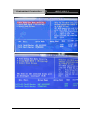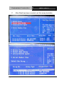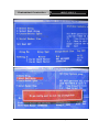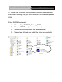
1
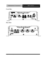
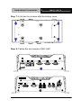
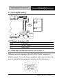
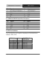
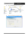
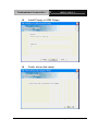
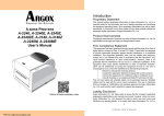
Embedded Controller
AEC-6811
AEC-6811
Fanless Embedded Controller
AMD GeodeTM LX 800 Processor
With Dual 100Base-TX Ethernet,
4 COM, Audio, 4 USB
AEC-6811 Manual 2nd Ed.
November 2009
Embedded Controller
AEC-6811
Copyright Notice
This document is copyrighted, 2009. All rights are reserved. The
original manufacturer reserves the right to make improvements to
the products described in this manual at any time without notice.
No part of this manual may be reproduced, copied, translated, or
transmitted in any form or by any means without the prior written
permission of the original manufacturer. Information provided in
this manual is intended to be accurate and reliable. However, the
original manufacturer assumes no responsibility for its use, or for
any infringements upon the rights of third parties that may result
from its use.
The material in this document is for product information only and is
subject to change without notice. While reasonable efforts have
been made in the preparation of this document to assure its
accuracy, AAEON assumes no liabilities resulting from errors or
omissions in this document, or from the use of the information
contained herein.
AAEON reserves the right to make changes in the product design
without notice to its users.
i
Embedded Controller
AEC-6811
Acknowledgments
•
Award is a trademark of Award Software International, Inc.
•
CompactFlash™ is a trademark of the Compact Flash
Association.
•
AMD, the AMD Arrow logo and combinations thereof are
trademarks of Advanced Micro Devices, Inc.
•
ITE is a trademark of Integrated Technology Express, Inc.
•
Microsoft Windows is a registered trademark of Microsoft
Corp.
•
IBM, PC/AT, PS/2, and VGA are trademarks of International
Business Machines Corporation.
®
All other product names or trademarks are properties of their
respective owners.
ii
Embedded Controller
AEC-6811
Packing List
Before you begin operating your PC, please make sure that the
following materials have been shipped:
1
AEC-6811 Embedded Controller
1
Keyboard & mouse cable
1
Phoenix Power Connector
2
Wallmount Brackets
2
RJ-45 to DB-9 Cables
1
Audio Cable
1
Screw Package
1
CD-ROM for manual (in PDF format) and
drivers
If any of these items should be missing or damaged, please
contact your distributor or sales representative immediately.
iii
Embedded Controller
AEC-6811
Safety & Warranty
1. Read these safety instructions carefully.
2. Keep this user's manual for later reference.
3. Disconnect this equipment from any AC outlet before cleaning. Do
not use liquid or spray detergents for cleaning. Use a damp cloth.
4. For pluggable equipment, the power outlet must be installed near
the equipment and must be easily accessible.
5. Keep this equipment away from humidity.
6. Put this equipment on a firm surface during installation. Dropping
it or letting it fall could cause damage.
7. The openings on the enclosure are for air convection. Protect the
equipment from overheating. DO NOT COVER THE OPENINGS.
8. Make sure the voltage of the power source is correct before
connecting the equipment to the power outlet.
9. Position the power cord so that people cannot step on it. Do not
place anything over the power cord.
10. All cautions and warnings on the equipment should be noted.
11. If the equipment is not used for a long time, disconnect it from the
power source to avoid damage by transient over-voltage.
12. Never pour any liquid into an opening. This could cause fire or
electrical shock.
13. Never open the equipment. For safety reasons, only qualified
service personnel should open the equipment.
14. If any of the following situations arises, get the equipment
checked by service personnel:
a.
The power cord or plug is damaged.
b.
Liquid has penetrated into the equipment.
c.
The equipment has been exposed to moisture.
iv
Embedded Controller
AEC-6811
d.
The equipment does not work well, or you cannot get it
to work according to the user’s manual.
e.
The equipment has been dropped and damaged.
f.
The equipment has obvious signs of breakage.
15. DO NOT LEAVE THIS EQUIPMENT IN AN ENVIRONMENT
WHERE THE STORAGE TEMPERATURE IS BELOW -20°C
(-4°F) OR ABOVE 60°C (140°F). IT MAY DAMAGE THE
EQUIPMENT.
FCC
This device complies with Part 15 FCC Rules.
Operation is subject to the following two
conditions: (1) this device may not cause
harmful interference, and (2) this device must
accept any interference received including
interference that may cause undesired
operation.
Caution:
There is a danger of explosion if the battery is incorrectly
replaced. Replace only with the same or equivalent type
recommended by the manufacturer. Dispose of used batteries
according to the manufacturer’s instructions and your local
government’s recycling or disposal directives.
v
Embedded Controller
AEC-6811
Below Table for China RoHS Requirements
产品中有毒有害物质或元素名称及含量
AAEON Boxer/ Industrial System
有毒有害物质或元素
部件名称
铅
汞
(Pb) (Hg)
印刷电路板
镉
六价铬 多溴联苯 多溴二苯
(Cd) (Cr(VI)) (PBB)
醚(PBDE)
×
○
○
○
○
○
×
○
○
○
○
○
×
○
○
○
○
○
×
○
○
○
○
○
硬盘
×
○
○
○
○
○
电源
×
○
○
○
○
○
及其电子组件
外部信号
连接器及线材
外壳
中央处理器
与内存
O:表示该有毒有害物质在该部件所有均质材料中的含量均在
SJ/T 11363-2006 标准规定的限量要求以下。
X:表示该有毒有害物质至少在该部件的某一均质材料中的含量超出
SJ/T 11363-2006 标准规定的限量要求。
备注:
一、此产品所标示之环保使用期限,系指在一般正常使用状况下。
二、上述部件物质中央处理器、内存、硬盘、电源为选购品。
vi
Embedded Controller
AEC-6811
Contents
Chapter 1 General Information
1.1 Introduction................................................................ 1-2
1.2 Features .................................................................... 1-3
1.3 Specifications ............................................................ 1-4
Chapter 2 Hardware Installation
2.1 Dimension ................................................................. 2-2
2.2 HDD Module Installation ........................................... 2-3
2.3 Wallmount Installation ............................................... 2-9
2.4 Jumper Setting .......................................................... 2-10
2.5 Clear CMOS Setting.................................................. 2-11
2.6 COM2 RS-232/422/485 Serial Port Connector ......... 2-11
2.7 COM1/2/3 RS-232 Serial Port Connector ................. 2-12
2.8 DIO Pin Definition...................................................... 2-12
Chapter 3 Award BIOS Setup
3.1 System Test and Initialization. .................................. 3-2
3.2 Award BIOS Setup .................................................... 3-3
Chapter 4 Driver Installation
4.1 Software Drivers........................................................ 4-2
4.2 Necessary to know .................................................... 4-3
4.3 Installing Driver for AEC-6811A ................................ 4-4
4.4 Installing Driver for AEC-6811B ................................ 4-20
vii
Embedded Controller
Appendix A
AEC-6811
Programming The Watchdog Timer
A.1 Programming for AEC-6811A ................................A-2
A.2 IT8712 Watchdog Timer Initial Program ................A-7
A.3 Programming for AEC-6811B ..............................A-12
A.4 W83627EHG Watchdog Timer Initial Program....A-16
Appendix B I/O Information
B.1 I/O Address Map ....................................................B-2
B.2 1st MB Memory Address Map ................................B-3
B.3 IRQ Mapping Chart ................................................B-4
B.4 DMA Channel Assignments...................................B-4
viii
Embedded Controller
AEC-6811
Appendix A Programming The Watchdog Timer
A.1 Programming ........................................................A-2
A.2 ITE8712 Watchdog Timer Initial Program ............A-6
ix
Embedded Controller
AEC-6811
Chapter
1
General
Information
Chapter 1 General Information 1- 1
Embedded Controller
AEC-6811
1.1 Introduction
The AEC-6811 is an Embedded Control PC, multiple IO ports and
Anti-vibration are the main design features of the AEC-6811. This
allows the AEC-6811 to be installed in a rugged transportation
environment despite high ambient vibration.
In addition to the fanless CPU, the AEC-6811 was use the AMD
LX800 500MHz CPU, features one Mini PCI expansion slots for
devices expansion. A DC power supply is commonly used in most
vehicles and factory equipments. The AEC-6811 can powered
by a DC 9~30V input with low power consumption and high
performance. You can also choose an additional external AC
power adapter for power redundancy purposes.
AAEON
provides flexible power choices for customers who choose the
AEC-6811.
Transportation has become part of most people’s life and forms a
necessary part of their lifestyle. From cars to trains to ships and
airplanes, we rely on those tools a lot.
The AEC-6811 is
designed to improve transportation control and enhance the
quality of our lives.
Chapter 1 General Information 1-2
Embedded Controller
AEC-6811
1.2 Features
•
Fanless Design with AMD GeodeTM LX 800 500MHz
Processor
•
1 Mini PCI Slot for Expansion
•
DC 9~30V Input with Phoenix Connector and Optional
External AC Power Adapter
•
CompactFlash for Version B
•
Optional 2.5” Hard Disk Drive Kit
•
Dual 100Base-TX Ethernet with RJ-45 Connectors
•
4 COM / 4 USB / Audio Ports
•
Operating Temperature: -5°C ~60°C (23°F~140°F)
•
Anti-vibration up to 5 g rms / Anti-shock Up to 50g
•
CE / FCC Class A Certified
Chapter 1 General Information 1- 3
Embedded Controller
AEC-6811
1.3 Specifications
System
CPU:
AMD GeodeTM LX 800 500MHz
Memory:
DDR SDRAM SODIMM x 1,
Max. 512MB; Installed 512MB.
Expansion:
Mini-PCI x 1
VGA:
D-sub 15 VGA Connector
Keyboard/Mouse: PS/2 Keyboard & Mouse
Ethernet:
10/100Base-TX Ethernet RJ-45
connector x 2
SSD:
SATA/IDE interface (Only
version A); IDE interface and
Type II CompactFlash™ slot
(Only version B)
Hard Disk Storage: 2.5” Slim Hard Disk Drive kit on
the Bottom cover
Serial Port:
RS-232 x 3; RS-232/422/485 x 1
Audio:
Mic-in / Line-in / Line-out, by an
extension cable
USB:
USB 2.0 x 4
Watchdog Timer:
Generates a time-out system
reset
Power Supply:
DC Input: 9V DC~30V DC
AC Input: External Power Adapter
Chapter 1 General Information 1-4
Embedded Controller
AEC-6811
(Optional)
System Control:
Power on / off switch x 1;Reset
button x 1
Indicator:
Power LED x 1;
HDD active LED x 1 (for IDE
HDD only)
Digital I/O:
8 ports
Mechanical and Environmental
Construction:
Aluminum Alloy chassis
Color:
Dark Blue
Mounting:
Wallmount (Default), DIN-Rail
Dimension:
8.35” (W) x 2.53” (H) x 4.21” (D)
(212.15mm x 64.2mm x 107mm)
Net Weight:
4.75lb (2.16kg)
Gross Weight:
8.36lb (3.8kg)
Operation Temperature:
23°F ~ 140°F (-5°C~60°C)(CFD)
Operation Humidity: 95%@40°C, non-condensing
Vibration:
5 g rms / 5~500Hz / random
operation (CompactFlash Disk);
1 g / 5~500Hz / random
operation (w/ Hard Disk Drive)
Shock:
50g peak acceleration (11
msec. duration); ComoactFlash
EMC:
CE/FCC class A
Chapter 1 General Information 1- 5
Embedded Controller
Front Side
Rear Side
Chapter 1 General Information 1-6
AEC-6811
Embedded Controller
AEC-6811
Chapter
2
Hardware
Installation
Chapter 2 Hardware Installation 2-1
Embedded Controller
AEC-6811
2.1 Dimension
AEC-6811-A1
Units: mm
AEC-6811-B1
Units: mm
Chapter 2 Hardware Installation 2 - 2
Embedded Controller
AEC-6811
2.2 HDD Module Installation
Step 1: Loosen the screw of the front bezel
Step 2: Open the HDD cover by loosening the screws on the
bottom of the chassis
Chapter 2 Hardware Installation 2 - 3
Embedded Controller
AEC-6811
Step 3: Loosen the screw of the rear bezel
Step 4.1: Connect the IDE Cable to the bottom of the chassis as
IDE Cable
the illustration below
Chapter 2 Hardware Installation 2 - 4
Embedded Controller
AEC-6811
Step 4.2: Connect the SATA Cable and Power cable and install to
the bottom side.
SATA Power
Insert I/O Board Side
W/LOCK
Note:
When installing the SATA HDD, the HDD LED will not active.
Chapter 2 Hardware Installation 2 - 5
Embedded Controller
AEC-6811
Step 5: Lock the Hard Disk Drive with four screws on the bottom
of the chassis
For IDE Installation
For SATA Installation
Chapter 2 Hardware Installation 2 - 6
Embedded Controller
AEC-6811
Step 6.1: Connect the IDE cable to the I/O board with IDE
connector
Step 6.2: Connect the SATA cable to the I/O board.
Chapter 2 Hardware Installation 2 - 7
Embedded Controller
AEC-6811
Step 7: Lock the four screws with the bottom cover
Step 8: Fasten the two screws of AEC-6811
Chapter 2 Hardware Installation 2 - 8
Embedded Controller
AEC-6811
2.3 Wallmount Installation
Fasten the brackets by screws.
Chapter 2 Hardware Installation 2 - 9
Embedded Controller
AEC-6811
2.4 Jumper Setting
JP3,JP4,JP5,JP6
JP6
+V5
JP4
RIXX
Default
JP5
JP3
COM1 Pin-9 Selection (JP3)
JP3
Function
1-2
+5V
3-4
RI1X for COM1 (Default)
COM2 Pin-9 Selection (JP4)
JP4
Function
1-2
+5V
3-4
RI2X for COM2 (Default)
COM3 Pin-9 Selection (JP5)
JP5
Function
1-2
+5V
3-4
RI3X for COM3 (Default)
COM4 Pin-9 Selection (JP6)
JP6
Function
1-2
+5V
3-4
RI4X for COM4 (Default)
Chapter 2 Hardware Installation 2 - 10
Embedded Controller
AEC-6811
2.5 Clear CMOS Setting
JP8
Default
JP8
Clear CMOS
RTC Battery Selection (JP8)
JP8
Funct ion
1-2
Normal (Default)
2-3
Clear CMOS
2.6 COM2 RS-232/422/485 Serial Port Connector
Different devices implement the RS-232/422/485 standard in
different ways. If you are having problems with a serial device, be
sure to check the pin assignments below for the connector.
4
2
5
1
9
6
7
8
Chapter 2 Hardware Installation 2 - 11
Embedded Controller
Pin
AEC-6811
Signal
Pin
Signal
1
DCD (422TXD-/485DATA-)
2
RXD (422RXD+)
3
TXD (422TXD+/485DATA+)
4
DTR (422RXD-)
5
GND
6
DSR
7
RTS
8
CTS
9
RI
10
N.C.
2.7 COM1/3/4 RS-232 Serial Port Connector
Pin
Signal
Pin
Signal
1
DCD
2
RXD
3
TXD
4
DTR
5
GND
6
DSR
7
RTS
8
CTS
9
RI
10
N.C.
2.8 DIO Pin Definition
The Pin definitions and registers mapping are illustrated below:
Address: 200h, 372h
BIOS Setting
Address
Port 1 @200h
Port 2 @200h
Port 3 @200h
Port 4 @200h
Port 5 @200h
Port 6 @200h
Port 7 @200h
Port 8 @372h
Bit 0
Bit 1
Bit 3
Bit 4
Bit 5
Bit 6
Bit 7
Bit 4
Chapter 2 Hardware Installation 2 - 12
W83977EG-AW
GPIO Setting
(GPIO 10)
(GPIO 11)
(GPIO 13)
(GPIO 14)
(GPIO 15)
(GPIO 16)
(GPIO 17)
(GPIO 24)
Embedded Controller
AEC-6 8 1 1
Chapter
3
Award
BIOS Setup
Chapter 3 Award BIOS Setup
3-1
Embedded Controller
AEC-6 8 1 1
3.1 System Test and Initialization
These routines test and initialize board hardware. If the routines
encounter an error during the tests, you will either hear a few short
beeps or see an error message on the screen. There are two kinds
of errors: fatal and non-fatal. The system can usually continue the
boot up sequence with non-fatal errors. Non-fatal error messages
usually appear on the screen along with the following instructions:
Press <F1> to RESUME
Write down the message and press the F1 key to continue the boot
up sequence.
System configuration verification
These routines check the current system configuration against the
values stored in the CMOS memory. If they do not match, the
program outputs an error message. You will then need to run the
BIOS setup program to set the configuration information in memory.
There are three situations in which you will need to change the
CMOS settings:
1.
You are starting your system for the first time
2.
You have changed the hardware attached to your system
3.
The CMOS memory has lost power and the configuration
information has been erased.
The AEC-6811 CMOS memory has an integral lithium battery
backup for data retention. However, you will need to replace the
complete unit when it finally runs down.
Chapter 3 Award BIOS Setup
3-2
Embedded Controller
AEC-6 8 1 1
3.2 Award BIOS Setup
Awards BIOS ROM has a built-in Setup program that allows users
to modify the basic system configuration. This type of information is
stored in battery-backed CMOS RAM so that it retains the Setup
information when the power is turned off.
Entering Setup
Power on the computer and press <Del> immediately. This will
allow you to enter Setup.
Standard CMOS Features
Use this menu for basic system configuration. (Date, time, IDE,
etc.)
Advanced BIOS Features
Use this menu to set the advanced features available on your
system.
Advanced Chipset Features
Use this menu to change the values in the chipset registers and
optimize your system performance.
Integrated Peripherals
Use this menu to specify your settings for integrated peripherals.
(Primary slave, secondary slave, keyboard, mouse etc.)
Power Management Setup
Use this menu to specify your settings for power management.
(HDD power down, power on by ring, KB wake up, etc.)
PnP/PCI Configurations
This entry appears if your system supports PnP/PCI.
Chapter 3 Award BIOS Setup
3-3
Embedded Controller
AEC-6 8 1 1
PC Health Status
This menu allows you to set the shutdown temperature for your
system.
Frequency/Voltage Control
Use this menu to specify your settings for auto detect DIMM/PCI
clock and spread spectrum.
Load Fail-Safe Defaults
Use this menu to load the BIOS default values for the
minimal/stable performance for your system to operate.
Load Optimized Defaults
Use this menu to load the BIOS default values that are factory
settings for optimal performance system operations. While AWARD
has designated the custom BIOS to maximize performance, the
factory has the right to change these defaults to meet their needs.
Set Supervisor/User Password
Use this menu to set Supervisor/User Passwords.
Save and Exit Setup
Save CMOS value changes to CMOS and exit setup.
Exit Without Saving
Abandon all CMOS value changes and exit setup.
You can refer to the "AAEON BIOS Item Description.pdf" file in
the CD for the meaning of each setting in this chapter.
Chapter 3 Award BIOS Setup
3-4
Embedded Controller
AEC-6811
Chapter
4
Driver
Installation
Chapter 4 Driver Installation 4-1
Embedded Controller
AEC-6811
4.1 Software Drivers
This chapter describes the operation and installation of the display
drivers supplied on the Supporting CD-ROM that are shipped with
your product. The onboard VGA adapter is based on the AMD LX
VGA Flat Panel/CRT controller. This controller offers a large set of
extended functions and higher resolutions. The purpose of the
enclosed software drivers is to take advantage of the extended
features of the AMD LX VGA Flat Panel/CRT controller.
Hardware Configuration
Some of the high-resolution drivers provided in this package will
work only in certain system configurations. If a driver does not
display correctly, try the following:
1. Change the display controller to CRT-only mode, rather than flat
panel or simultaneous display mode. Some high-resolution
drivers will display correctly only in CRT mode.
2. If a high-resolution mode does not support your system, try to
use a lower-resolution mode. For example, 1024 x 768 mode will
not work on some systems, but 800 x 600 mode supports the
most.
Chapter 4 Driver Installation 4-2
Embedded Controller
AEC-6811
4.2 Necessary to Know
The instructions in this manual assume that you understand
elementary concepts of MS-DOS and the IBM Personal Computer.
Before you attempt to install any driver from the Supporting
CD-ROM, you should:
Know how to copy files from a CD-ROM to a directory on the
hard disk
Understand the MS-DOS directory structure
If you are uncertain about any of these concepts, please refer
to the DOS or OS/2 user reference guides for more
information before you proceed with the installation.
Before you begin
The Supporting CD-ROM contains different drivers for
corresponding Windows OS, please choose the specific driver for
your Windows OS.
Chapter 4 Driver Installation 4-3
Embedded Controller
AEC-6811
4.3 Installing Driver for AEC-6811A
Installing VGA Driver
Win XP / Win XPe VGA
Place the Driver CD-ROM into your CD-ROM drive and follow the
steps below to install.
1. Click on Start button
2. Click on Settings button
3. Click on Control Panel button
4. Click on System button
5. Select Hardware and click on Device Manager…
6. Double click on Video Controller (VGA Compatible)
7. Click on Update Driver…
8. Click on Next
9. Select Search for a suitable driver…, then click on Next
10. Select Specify a location, then click on Next
11. Click on Browse
12. Select “lx_win” file from CD-ROM (Drivers/Step 1 –
LX_Graphics) then click on Open
13. Click on OK
14. Click on Next
15. Click on Yes
16. Click on Finish
Note: The user must install this system driver before install other
device drivers.
Chapter 4 Driver Installation 4-4
Embedded Controller
AEC-6811
Installing AES Driver
Win XP / Win XPe AES
Place the Driver CD-ROM into your CD-ROM drive and follow the
steps below to install.
1. Click on Start button
2. Click on Settings button
3. Click on Control Panel button
4. Click on System button
5. Select Hardware and click on Device Manager…
6. Double click on Entertainment Encryption/Decryption
Controller
7. Click on Update Driver…
8. Click on Next
9. Select Search for a suitable driver…, then click on Next
10. Select Specify a location, then click on Next
11. Click on Browse
12. Select “LXAES” file from CD-ROM (Driver/Step 2 – AES) then
click on Open
13. Click on OK
14. Click on Next
15. Click on Finish
Chapter 4 Driver Installation 4-5
Embedded Controller
AEC-6811
Installing PCI to ISA Bridge Driver
Win XP / Win XPe System
Place the Driver CD-ROM into your CD-ROM drive and follow the
following steps to install.
1. Click on Start button
2. Click on Settings button
3. Click on Control Panel button
4. Click on System button
5. Select Hardware and click on Device Manager…
6. Double click on Other PCI Bridge Device
7. Click on Update Driver…
8. Click on Next
9. Select Search for a suitable driver…, then click on Next
10. Select Specify a location, then click on Next
11. Click on Browse
12. Select “Ite” file from CD-ROM (Driver/Step 3- PCI to ISA
Bridge ) then click on Open
13. Click on OK
14. Click on Next
15. Click on Finish
Chapter 4 Driver Installation 4-6
Embedded Controller
AEC-6811
Installing Ethernet Driver
1. Click on the Step 4 –LAN-Realtek8139 folder
2. Double click on the Setup file located in the folder
3. Follow the instructions that the window shows
4. The system will help you install the driver automatically
Installing LAN 82551er Driver
Win XP / Win XPe System
Place the Driver CD-ROM into your CD-ROM drive and follow the
following steps to install.
1. Click on Start button
2. Click on Settings button
3. Click on Control Panel button
4. Click on System button
5. Select Hardware and click on Device Manager...
6. Click on "+" of Network adapters
7. Double click on Intel(R) 8255xER PCI Adapter
8. Click on Update Driver...
9. Click on Next
10. Select Search for a suitable driver..., then click on Next
11. Select Specify a location, then click on Next
12. Click on Browse
13. Select "Net559ER.INF" file from CD-ROM (Driver/Step 5LAN-Intel 82551er Driver) and then click on Open
14. Click on OK
Chapter 4 Driver Installation 4-7
Embedded Controller
AEC-6811
15. Click on Next
16. Click on Finish
Installing Audio Driver
Win XP / Win XPe Audio
Place the Driver CD-ROM into your CD-ROM drive and follow the
steps below to install.
1. Click on Start button
2. Click on Settings button
3. Click on Control Panel button
4. Click on System button
5. Select Hardware and click on Device Manager…
6. Double click on Multimedia Audio Controller
7. Click on Update Driver…
8. Click on Next
9. Select Search for a suitable driver…, then click on Next
10. Select Specify a location, then click on Next
11. Click on Browse
12. Select “LXWDMAu” file from CD-ROM (Drivers/Step 6 –
Audio) then click on Open
13. Click on OK
14. Click on Next
15. Click on Yes
16. Click on Finish
Chapter 4 Driver Installation 4-8
Embedded Controller
AEC-6811
Installing RAID Driver
Step 7 – Install VRAID Driver
Please follow the application note to install the Step 7VRAID_Driver_V550B
Application Note:
Window Operating System cannot recognize the driver of chip
VT6421 and treat it as a third-part driver. Please follow below
steps to install the driver with Operating System.
1. Creating a Drive Disk: copy the SATA driver from AAEON CD to
floppy disk before install OS.
Click on Step 7-VRAID_Driver_V550B
Click on VRAIDDrv (see below picture)
Chapter 4 Driver Installation 4-9
Embedded Controller
AEC-6811
Click on DriverDiskPrep.exe (see below picture)
Click on the OS what you are going to install.
Chapter 4 Driver Installation 4-10
Embedded Controller
AEC-6811
Install Floppy or USB Floppy
Finish: driver disk ready.
Chapter 4 Driver Installation 4-11
Embedded Controller
AEC-6811
2. Following are the raid configuration steps.
A.
Press <Tab> key to enter Raid BIOS setup
(Raid BIOS only enable when SATA HDD connected)
B.
Create Array
Chapter 4 Driver Installation 4-12
Embedded Controller
AEC-6811
Chapter 4 Driver Installation 4-13
Embedded Controller
C.
AEC-6811
After Raid has been created, set this array bootable.
Chapter 4 Driver Installation 4-14
Embedded Controller
AEC-6811
Chapter 4 Driver Installation 4-15
Embedded Controller
D.
AEC-6811
Now the Raid Array is ready for OS installation
3. Insert your Windows CD, and then restart the computer
4. Follow the on-screen instructions to begin the Windows
installation.
5. When prompted to install a third-party driver, press F6.
Note: When F6 is active, a prompt appears at the bottom of the
screen for only 5 seconds. If you miss your chance to press F6,
restart your computer.
Chapter 4 Driver Installation 4-16
Embedded Controller
AEC-6811
6. Insert the driver disk, and then wait until you are prompted to
install a driver.
7. Press S to specify the driver is on a floppy disk, and then press
Enter.
Chapter 4 Driver Installation 4-17
Embedded Controller
AEC-6811
8. The computer reads the disk
9. When the SATA driver is found, press Enter.
Chapter 4 Driver Installation 4-18
Embedded Controller
AEC-6811
10. Follow the on-screen instructions to complete the installation.
After finish installing OS, you have to install VIA Raid management
Utility.
Setup RAID Management
A. Click on Step 7-VRAID_Driver_V550B
B. Click on SETUP.exe (see below picture)
C. Follow the instructions that the window shows
D. The system will help you install the driver automatically
Chapter 4 Driver Installation 4-19
Embedded Controller
AEC-6811
4.4 Installing Driver for AEC-6811B
Installing VGA Driver
Win XP / Win XPe VGA
Place the Driver CD-ROM into your CD-ROM drive and follow the
steps below to install.
1. Click on Start button
2. Click on Settings button
3. Click on Control Panel button
4. Click on System button
5. Select Hardware and click on Device Manager…
6. Double click on Video Controller (VGA Compatible)
7. Click on Update Driver…
8. Click on Next
9. Select Search for a suitable driver…, then click on Next
10. Select Specify a location, then click on Next
11. Click on Browse
12. Select “lx_win” file from CD-ROM (Drivers/Step 1 –
LX_Graphics) then click on Open
13. Click on OK
14. Click on Next
15. Click on Yes
16. Click on Finish
Note: The user must install this system driver before install other
device drivers.
Chapter 4 Driver Installation 4-20
Embedded Controller
AEC-6811
Installing AES Driver
Win XP / Win XPe AES
Place the Driver CD-ROM into your CD-ROM drive and follow the
steps below to install.
1. Click on Start button
2. Click on Settings button
3. Click on Control Panel button
4. Click on System button
5. Select Hardware and click on Device Manager…
6. Double click on Entertainment Encryption/Decryption
Controller
7. Click on Update Driver…
8. Click on Next
9. Select Search for a suitable driver…, then click on Next
10. Select Specify a location, then click on Next
11. Click on Browse
12. Select “LXAES” file from CD-ROM (Driver/Step 2 – AES) then
click on Open
13. Click on OK
14. Click on Next
15. Click on Finish
Chapter 4 Driver Installation 4-21
Embedded Controller
AEC-6811
Installing PCI to ISA Bridge Driver
Win XP / Win XPe System
Place the Driver CD-ROM into your CD-ROM drive and follow the
following steps to install.
1. Click on Start button
2. Click on Settings button
3. Click on Control Panel button
4. Click on System button
5. Select Hardware and click on Device Manager…
6. Double click on Other PCI Bridge Device
7. Click on Update Driver…
8. Click on Next
9. Select Search for a suitable driver…, then click on Next
10. Select Specify a location, then click on Next
11. Click on Browse
12. Select “Ite” file from CD-ROM (Driver/Step 3- PCI to ISA
Bridge ) then click on Open
13. Click on OK
14. Click on Next
15. Click on Finish
Chapter 4 Driver Installation 4-22
Embedded Controller
AEC-6811
Installing Ethernet Driver
1. Click on the Step 4 –LAN-Realtek8139 folder
2. Double click on the Setup file located in the folder
3. Follow the instructions that the window shows
4. The system will help you install the driver automatically
Installing LAN 82551er Driver
Win XP / Win XPe System
Place the Driver CD-ROM into your CD-ROM drive and follow the
following steps to install.
1. Click on Start button
2. Click on Settings button
3. Click on Control Panel button
4. Click on System button
5. Select Hardware and click on Device Manager...
6. Click on "+" of Network adapters
7. Double click on Intel(R) 8255xER PCI Adapter
8. Click on Update Driver...
9. Click on Next
10. Select Search for a suitable driver..., then click on Next
11. Select Specify a location, then click on Next
12. Click on Browse
13. Select "Net559ER.INF" file from CD-ROM (Driver/Step 5LAN-Intel 82551er Driver) and then click on Open
14. Click on OK
Chapter 4 Driver Installation 4-23
Embedded Controller
AEC-6811
15. Click on Next
16. Click on Finish
Installing Audio Driver
Win XP / Win XPe Audio
Place the Driver CD-ROM into your CD-ROM drive and follow the
steps below to install.
1. Click on Start button
2. Click on Settings button
3. Click on Control Panel button
4. Click on System button
5. Select Hardware and click on Device Manager…
6. Double click on Multimedia Audio Controller
7. Click on Update Driver…
8. Click on Next
9. Select Search for a suitable driver…, then click on Next
10. Select Specify a location, then click on Next
11. Click on Browse
12. Select “LXWDMAu” file from CD-ROM (Drivers/Step 6 –
Audio) then click on Open
13. Click on OK
14. Click on Next
15. Click on Yes
16. Click on Finish
Chapter 4 Driver Installation 4-24
Embedded Controller
AEC-6 8 1 1
Appendix
A
Programming the
Watchdog Timer
Appendix A Programming the Watchdog Timer A-1
Embedded Controller
AEC-6 8 1 1
A.1 Programming for AEC-6811A
AEC-6811A utilizes ITE 8712 chipset as its watchdog timer
controller.
Below are the procedures to complete its configuration and the
AAEON intial watchdog timer program is also attached based on
which you can develop customized program to fit your application.
Configuring Sequence Description
After the hardware reset or power-on reset, the ITE 8712 enters the
normal mode with all logical devices disabled except KBC. The
initial state (enable bit ) of this logical device (KBC) is determined
by the state of pin 121 (DTR1#) at the falling edge of the system
reset during power-on reset.
Appendix A Programming the Watchdog Timer A-2
Embedded Controller
AEC-6 8 1 1
There are three steps to complete the configuration setup: (1) Enter
the MB PnP Mode; (2) Modify the data of configuration registers; (3)
Exit the MB PnP Mode. Undesired result may occur if the MB PnP
Mode is not exited normally.
(1) Enter the MB PnP Mode
To enter the MB PnP Mode, four special I/O write operations are to
be performed during Wait for Key state. To ensure the initial state of
the key-check logic, it is necessary to perform four write opera-tions
to the Special Address port (2EH). Two different enter keys are
provided to select configuration ports (2Eh/2Fh) of the next step.
Appendix A Programming the Watchdog Timer A-3
Embedded Controller
AEC-6 8 1 1
(2) Modify the Data of the Registers
All configuration registers can be accessed after entering the MB
PnP Mode. Before accessing a selected register, the content of
Index 07h must be changed to the LDN to which the register
belongs, except some Global registers.
(3) Exit the MB PnP Mode
Set bit 1 of the configure control register (Index=02h) to 1 to exit the
MB PnP Mode.
Appendix A Programming the Watchdog Timer A-4
Embedded Controller
AEC-6 8 1 1
WatchDog Timer Configuration Registers
Configure Control (Index=02h)
This register is write only. Its values are not sticky; that is to say, a
hardware reset will automatically clear the bits, and does not
require the software to clear them.
WatchDog Timer Control Register (Index=71h, Default=00h)
Appendix A Programming the Watchdog Timer A-5
Embedded Controller
AEC-6 8 1 1
WatchDog Timer Configuration Register (Index=72h,
Default=00h)
WatchDog Timer Time-out Value Register (Index=73h,
Default=00h)
Appendix A Programming the Watchdog Timer A-6
Embedded Controller
AEC-6 8 1 1
A.2 IT8712 Watchdog Timer Initial Program
.MODEL SMALL
.CODE
Main:
CALL Enter_Configuration_mode
CALL Check_Chip
mov cl, 7
call Set_Logic_Device
;time setting
mov cl, 10 ; 10 Sec
dec al
Watch_Dog_Setting:
;Timer setting
mov al, cl
mov cl, 73h
call Superio_Set_Reg
;Clear by keyboard or mouse interrupt
mov al, 0f0h
mov cl, 71h
call Superio_Set_Reg
;unit is second.
mov al, 0C0H
mov cl, 72h
call Superio_Set_Reg
Appendix A Programming the Watchdog Timer A-7
Embedded Controller
AEC-6 8 1 1
; game port enable
mov cl, 9
call Set_Logic_Device
Initial_OK:
CALL Exit_Configuration_mode
MOV AH,4Ch
INT 21h
Enter_Configuration_Mode PROC NEAR
MOV SI,WORD PTR CS:[Offset Cfg_Port]
MOV DX,02Eh
MOV CX,04h
Init_1:
MOV AL,BYTE PTR CS:[SI]
OUT DX,AL
INC SI
LOOP Init_1
RET
Enter_Configuration_Mode ENDP
Exit_Configuration_Mode PROC NEAR
MOV AX,0202h
CALL Write_Configuration_Data
Appendix A Programming the Watchdog Timer A-8
Embedded Controller
AEC-6 8 1 1
RET
Exit_Configuration_Mode ENDP
Check_Chip PROC NEAR
MOV AL,20h
CALL Read_Configuration_Data
CMP AL,87h
JNE Not_Initial
MOV AL,21h
CALL Read_Configuration_Data
CMP AL,12h
JNE Not_Initial
Need_Initial:
STC
RET
Not_Initial:
CLC
RET
Check_Chip ENDP
Read_Configuration_Data PROC NEAR
MOV DX,WORD PTR CS:[Cfg_Port+04h]
OUT DX,AL
Appendix A Programming the Watchdog Timer A-9
Embedded Controller
AEC-6 8 1 1
MOV DX,WORD PTR CS:[Cfg_Port+06h]
IN AL,DX
RET
Read_Configuration_Data ENDP
Write_Configuration_Data PROC NEAR
MOV DX,WORD PTR CS:[Cfg_Port+04h]
OUT DX,AL
XCHG AL,AH
MOV DX,WORD PTR CS:[Cfg_Port+06h]
OUT DX,AL
RET
Write_Configuration_Data ENDP
Superio_Set_Reg proc near
push ax
MOV DX,WORD PTR CS:[Cfg_Port+04h]
mov al,cl
out dx,al
pop ax
inc dx
out dx,al
ret
Superio_Set_Reg endp.Set_Logic_Device proc near
Set_Logic_Device proc near
Appendix A Programming the Watchdog Timer A-10
Embedded Controller
AEC-6 8 1 1
push ax
push cx
xchg al,cl
mov cl,07h
call Superio_Set_Reg
pop cx
pop ax
ret
Set_Logic_Device endp
;Select 02Eh->Index Port, 02Fh->Data Port
Cfg_Port DB 087h,001h,055h,055h
DW 02Eh,02Fh
END Main
Note: Interrupt level mapping
0Fh-Dh: not valid
0Ch: IRQ12
.
.
03h: IRQ3
02h: not valid
01h: IRQ1
00h: no interrupt selected
Appendix A Programming the Watchdog Timer A-11
Embedded Controller
AEC-6 8 1 1
A.3 Programming for AEC-6811B
AEC-6811B utilizes W83627E HG chipset as its watchdog timer
controller.
Below are the procedures to complete its configuration and the
AAEON intial watchdog timer program is also attached based on
which you can develop customized program to fit your application.
Configuring Sequence Description
Unlock W83627EHG
Select register of
watchdog timer
Enable the function of
the watchdog timer
Use the function of the
watchdog timer
Lock W83627EHG
There are three steps to complete the configuration setup:
(1) Enter the W83627EHG config Mode
(2) Modify the data of configuration registers
Appendix A Programming the Watchdog Timer A-12
Embedded Controller
AEC-6 8 1 1
(3) Exit the W83627EHG config Mode. Undesired result may
occur if the config Mode is not exited normally.
(1) Enter the W83627EHG config Mode
To enter the W83627EHG config Mode, two special I/O write
operations are to be performed during Wait for Key state. To
ensure the initial state of the key-check logic, it is necessary to
perform two write operations to the Special Address port (2EH).
The different enter keys are provided to select configuration ports
(2Eh/2Fh) of the next step.
Address Port
87h,87h:
2Eh
Data Port
2Fh
(2) Modify the Data of the Registers
All configuration registers can be accessed after entering the config
Mode. Before accessing a selected register, the content of Index
07h must be changed to the LDN to which the register belongs,
except some Global registers.
(3) Exit the W83627EHG config Mode
The exit key is provided to select configuration ports (2Eh/2Fh) of
the next step.
0aah:
Address Port
Data Port
2Eh
2Fh
WatchDog Timer Register I (Index=F5h, Default=00h)
CRF5 (PLED mode register. Default 0 x 00)
Bit 7-6
: select PLED mode
= 00 Power LED pin is tri-stated.
= 01 Power LED pin is drived low.
Appendix A Programming the Watchdog Timer A-13
Embedded Controller
AEC-6 8 1 1
= 10 Power LED pin is a 1Hz toggle pulse
with 50 duty cycle.
= 11 Power LED pin is a 1/4Hz toggle pulse
with 50 duty cycle.
Bit 5-4
: Reserved
Bit 3
: select WDTO count mode.
Bit 2
=0
second
=1
minute
: Enable the rising edge of keyboard Reset
(P20) to force Time-out event.
= 0 Disable
= 1 Enable
Bit 1-0
: Reserved
WatchDog Timer Register II (Index=F6h, Default=00h)
Bit 7-0
= 0 x 00 Time-out Disable
= 0 x 01 Time-out occurs after 1
second/minute
= 0 x 02 Time-out occurs after 2
second/minutes
= 0 x 03 Time-out occurs after 3
second/minutes
… … … … … … … … … … … … ..
= 0 x FF Time-out occurs after 255
second/minutes
Appendix A Programming the Watchdog Timer A-14
Embedded Controller
AEC-6 8 1 1
WatchDog Timer Register III (Index=F7h, Default=00h)
Bit 7
Bit 6
: Mouse interrupt reset Enable or Disable
=1
Watchdog Timer is reset upon a
Mouse interrupt
=0
Watchdog Timer is not affected by
Mouse interrupt
: Keyboard interrupt reset Enable or
Disable
=1
Watchdog Timer is reset upon a
Keyboard interrupt
=0
Watchdog Timer is not affected by
Keyboard interrupt
Bit 5
: Force Watchdog Timer Time-out. Write
Only
=1
Force Watchdog Timer time-out
event: this bit is self-clearing
Bit 4
Bit 3-0
: Watchdog Timer Status. R/W
=1
Watchdog Timer time-out occurred
=0
Watchdog Timer counting
: These bits select IRQ resource for
Watchdog. Setting of 2 selects SMI.
Appendix A Programming the Watchdog Timer A-15
Embedded Controller
AEC-6 8 1 1
A.4 W83627EHG Watchdog Timer Initial Program
Example: Setting 10 sec. as Watchdog timeout interval
;///////////////////////////////////////////////////////////////////////////////////////////////
Mov dx,2eh
;Enter W83627EHG config mode
Mov al,87h
(out 87h to 2eh twice)
Out dx,al
Out dx,al
;///////////////////////////////////////////////////////////////////////////////////////////////
Mov al,07h
Out dx,al
Inc dx
Mov al,08h
;Select Logical Device 8 (GPIO Port
2)
Out dx,al
;///////////////////////////////////////////////////////////////////////////////////////////////
Dec dx
Mov al,30h
;CR30 (GP20~GP27)
Out dx,al
Inc dx
Mov al,01h
;Activate GPIO2
Out dx,al
Appendix A Programming the Watchdog Timer A-16
Embedded Controller
AEC-6 8 1 1
;///////////////////////////////////////////////////////////////////////////////////////////////
Dec dx
Mov al,0f5h
;CRF5 (PLED mode register)
Out dx,al
Inc dx
In al,dx
And al,not 08h
;Set second as counting unit
Out dx,al
;///////////////////////////////////////////////////////////////////////////////////////////////
Dec dx
Mov al,0f6h
; CRF6
Out dx,al
Inc dx
Mov al,10
;Set timeout interval as 10 sec.
Out dx,al
;///////////////////////////////////////////////////////////////////////////////////////////////
Dec dx
Mov al,0aah
;Exit W83627EHG config mode
(out 0aah to 2eh once)
Out dx,al
;///////////////////////////////////////////////////////////////////////////////////////////////
Appendix A Programming the Watchdog Timer A-17
Embedded Controller
AEC-6811
Appendix
B
I/O Information
Appendix B I/O Information B - 1
Embedded Controller
B.1 I/O Address Map
Appendix B I/O Information B - 2
AEC-6811
Embedded Controller
AEC-6811
B.2 1st MB Memory Address Map
Appendix B I/O Information B - 3
Embedded Controller
B.3 IRQ Mapping Chart
B.4 DMA Channel Assignments
Appendix B I/O Information B - 4
AEC-6811