1
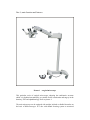
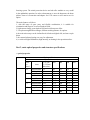
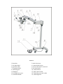
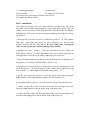
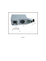
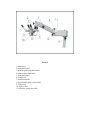
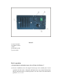
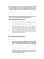
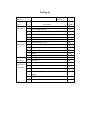
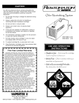
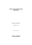
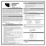
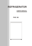
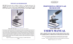
Operating Standing Surgical Microscope User Manual Content 1, Main function and features 2, Characteristics and main specifications 3, Installation 4, Operation method 5, Maintenance and attention 6, Accessories and options 7, Packing list Part 1, main function and features Picture 1 surgical microscope This particular series of surgical microscopes, adopting the combinative structure which is in fashion internationally, are suitable for the examination and surgery in the dentistry, ENT and ophthalmology. Refer to picture 1. The main microscope can be equipped with straight, inclined or tiltable binoculars on the basis of different usages. It is also with manual focusing system or motorized focusing system. The retinal protection device and red reflex module are very useful in the ophthalmic operation. In order to demonstrate or store the document, the beam splitter, observer’s monocular and adaptor for CCD camera or still camera are for option. The main features as follows: 1, with full range of spare parts, and flexible combination, it is suitable for examination and surgeries in several kinds of fields. 2, high-contrast image, great depth of field and excellent stereo effect. 3, 5-step drum magnification changer, different working distance for options. 4, the main microscope can be inclined back & forth and right & left, and move up & down. 5, the counter-balanced spring arm, easy for adjustment. 6, co-axial cold light illumination, high intensity, no heating in the operation surface. Part 2, main optical properties and structure specifications 1, optical properties Value on wheel 0.4 0.6 1 1.6 2.5 magnification Visual field magnification Visual field magnification Visual field magnification Visual field magnification Basic specifications Objective lens (mm) 200 175( with f’=125mm binocular) 3.6 4.2 56 53 5.4 6.2 35 8.9 10.4 20.7 14.2 17.4 12.3 22.3 25.5 Visual field 9 items 8.3 250 300 400 3.4 66 4.9 44 8.3 25.8 13.9 15.4 20.4 2.8 80 4.1 53 6.9 31 11.6 18.5 17 2.1 106 3.1 70 5.2 41.4 8.7 24.6 12.7 10.4 12.5 16.6 2, structure specifications Eyepiece: 12.5X Diopter adjustment: -5D to +5D interpupillary distance: 55-75 mm range of manual focusing or motorized focusing: 40 mm speed of motorized focusing: 3mm/s extended arm: 1040 mm (max.) elevation stroke for spring arm: 350 mm rotation angle: 270 degree the diameter of illumination field: 56 – 80 mm 3, electrical parameters brightness: not less than 80000 Lux halogen lamp: 15V/150W power supply: 220V/50Hz or 110V/60Hz Picture 2 1, binoculars 3, lock hand-wheel 5, optic fiber cable 7, fixing hand-wheel 9, connecting part 11, flank base 13, cold light source arm 15, inclination handle 2, main microscope 4, counter-balanced arm 6, electric cable and it’s connector 8, lock hand-wheel 10, column and bar 12, pedal control switch 14, connecting screw and washer 16, connecting block 17, connecting hand-wheel 18, hand-wheel 19, beam splitter 20, adaptor for CCD camera 21, connectors for power supply and pedal control switch 22, magnification changer wheel Part 3, installation Two cartons for package, one covers: column and bar, cold light source arm, spring arm, pedal control switch, connecting block, electric cable, power supply cable, etc; Another covers two pieces of flank base, binocular, main microscope, beamsplitter and adaptor for CCD camera if ordered, mechanical adjusting system. Refer to Picture 2 & Picture 3. 1, discharge the screws from two pieces of flank bases (Picture 2, 11). Then, connect flank bases with column and bar by the screws (picture 2, 10), with the tools attached, fix them and make them vertical. Be very careful while connecting in order to avoid any damage to surface painting on base and bar. 2, discharge the screws ( picture 3, 1) from the cold light source arm, connect the 8-pins adaptor ( Picture 3, 2) with 8-pins adaptor at the top of column, then place the cold light source arm on the top of column, tighten four pieces of screws. 3, insert the counter-balanced arm into the socket at the forehead of cold light source arm (picture 2, 5), fix them by the hand wheel. (picture 2, 14) 4, discharge the screw form the counter-balanced arm, insert the connecting block into the socket (picture 2, 16) at the forehead of counter-balanced arm, tighten that screw, refer to Picture 3, 5. Finally, tighten fixing hand-wheel (picture 2, 7). 5, put the main microscope (picture 2, 2) into the socket at the connecting block, tighten another connecting hand-wheel (which is not shown on picture 2 ). 6, insert the binoculars (picture 2, 1) into the main microscope, fasten the lock screw. 7, connect the optic fiber cable with main microscope and cold light source arm, adjust the length and place it into the plastic clasp on the spring arm. 8, connect the electric cable with the motorized focusing system and cold light source arm, adjust the length, place it into the plastic clasp on the spring arm. Picture 3 Picture 4 1, hand-wheel 2, fixing hand-wheel 3, up-down positioning hand-wheel 4, balance adjust hand wheel 5, fixing hand wheel 6, fixing wheel 7, inclination handle 8, magnification changer hand-wheel 9, fixing screw 10, objective lens 11, socket for optical fiber cable Picture 5 1, screws on panel 2, brightness switch 3, fuses 4, bulb-shift switch 5, power switch Part 4, operation 1, the operation for main microscope, refer to Picture 4 & Picture 5 (1) after the installation, move the surgical microscope to the suitable place for the operation, lock the castors. Adjust the cold light source arm, counter-balanced arm and the main microscope to suitable position, screw the relative lock hand-wheels (picture 4, 1, 2, 3, 5, 6) (2) hold the main microscope by hand, and release the up-down positioning hand-wheel (picture 4, 3), swivel the balance hand-wheel (picture 2, 1) till the main microscope can move up-down with free. (It has already been adjusted well before ex-works, but, it can only be made suitable adjustment when using the accessories ). (3) turn on the power switch (picture 5, 5), swivel the brightness switch (picture 5, 3) to “on” position, release the relative lock hand-wheels and move the main microscope to the place over the operation surface with the height of the working distance ( it depends on focal length of the objective lens), till the images can be got in the binoculars, tighten the relative lock hand-wheels. (4) adjust the binocular by hand to get the suitable papillary distance. (5) swivel the magnification-changer hand-wheel (picture 5, 8) to get suitable magnification. (6) adjust the brightness switch to get suitable illumination on the operation surface. (7) to get the best clear image by the motorized up-down focus system or manual focus system. (8) if two eyes with different diopter, adjust the diopter on the eyepiece for each eye. (9) back-forth inclination adjustment: swivel the inclination hand-wheel (picture 4, 7) by back and forth and place the main microscope to suitable position. (10)right and left inclination adjustment: release the hand-wheel (picture 4, 1), adjust the main microscope right and left to suitable position by inclination handle (picture 4, 7). Then lock hand wheel (picture 4, 1) again. (11)This surgical microscope is for Ophthalmology with green filter and retinal protection device. (12) after the operation, swivel the brightness switch to “off” position, several minutes later, turn the power switch to “off” position, release the relative lock hand-wheel, and make arm and main microscope be in a suitable position, and put on the plastic-proof cover. Release the lockers on the caster, and move the unit to a suitable place. 2, the usage of the accessories (1) release the fixing screw (picture 4, 9), take off the binoculars, put on the beam splitter ( picture 2, 19), connecting it with main microscope, then put on the binoculars again., fix the screws later. (2) Connecting the monocular or adaptor for CCD camera (picture 2, 20) with beam splitter, screw the lock loop tightly, then the pictures can be got in the observer’s monocular or monitor after the CCD camera and monitor connect with adaptor for CCD camera, simultaneously with the binoculars. If necessary, adjust the iris diaphragm on the adaptor for CCD camera according to the brightness on the monitor. (3) The shift of objective lens: loose frame with the objective lens (picture 4, 10) and put on the suitable one according to different operation requirement. Note: for the surgical microscope mentioned in this user manual, the objective lens (f’=175mm) is with red reflex module, and can not be shifted. 3, The shift of illumination and bulb replacement (i) (ii) (iii) the unit adopts twin-bulb cold light source. During the operation, if the bulb is broken down, put the optical fiber cable into another socket on the cold light source (picture 4, 11). At the same time, shift the bulb-shift switch (picture 5, 6). then the illumination can be got again. After the broken bulb cool down, loose the screw in the panel (picture 5,2) open the panel, release the screw which fixes the bulb by screw-driver, replace it with new one, then fix it. Close the panel and fasten the screw. If the fuse is damaged, loose the fuse cover (picture 5, 4) and replace it with new one. If the fuse is damaged continuously, please let the electric technician check the reason with reference of electric diagram. After solving the problem, put on the new fuse. Part 5, maintenance and special attentions (1) Maintenance (i) (ii) the place where the unit stays and is maintained should be clean and be far away form the corrosive and volatile material, such as dust, moisture, acid or alkaline, etc. After the usage, the plastic dust-proof cover should be put on. Pay attention to keep the objective lens clean. The fingers are not allowed to touch the objective lens directly. If there is dust on the lens’ surface, flick it with the clean brush. If there is some contaminative oil or stain on the objective lens, clean them by the absorbent cotton with a little mixture liquid of ethyl alcohol (30%) and ethyl ether (70%).While cleaning the lens, the mixture liquid is not allowed to permeate into the objective lens to prevent the de-gumming or mustiness. (iii) Optical fiber cable consists of fine glass fiber, and can not bear bending force. If needing bending, the bending angle should be less than 90 degree to avoid the damage. (2) special attentions: (i) (ii) (iii) (iv) (v) (vi) (vii) the unit belongs to Class B, grade one, and needs the power supply with good grounding while working. This aspect should be checked to ensure the safety. The power cable in the unit is for transferring the electricity, can not be pulled with force. The power cable concerns the safety of operator, and should be protected well. If any damage on the protective-cover of power cable, please change new power cable immediately. The plug should not be wet. While moving the unit, the power cable should be winded the handle on the column. While change the fuse, please turn off the power. The pedal control switch is used for focusing, when it reaches the limited point, the focusing stops. Then, release the pedal control switch at once or run the pedal control switch in reverse direction. After the usage, do not locate the mechanical structure on the limited position to avoid any damage. While moving the unit, hold the handle on the column. Move the unit slowly to avoid any toppling or clashing. The unit with one year guarantee. If any problem, please call local agent or maker. Part 6, accessories and options (1) Accessories Plastic dust-proof cover fuse 2A fuse 10 A hexagonal spanner mini-screw driver flannelette brush 1 5 5 3 1 1 1 (2) options beam splitter adaptor for CCD camera 1 pcs 1 pcs pcs pcs pcs pcs pcs pcs pcs Picture 6 Packing list Model Item Main unit Spare part document Serial No. No. 1 2 3 Description Surgical microscope’s optical head Arm, column and base Pedal control switch Quantity 1 set 1 set 1 set 4 Power cable and connecting electric cable 2 pcs 5 6 1 2 Optical fiber cable Objective lens ( standard supply) Plastic dust-proof cover fuse 1 pcs 1 pcs 1 pcs 10 pcs 3 Hexagon spanner 3 pcs 4 5 6 1 2 1 Mini-screw driver Brush Flannelette cloth Manual pack list Beam splitter 1 pcs 1 pcs 1 pcs 1 pcs 1 pcs Accessories 2 for options 3 4 Adaptor for CCD camera Observer’s monocular 5 Objective: f’=175mm, 200mm, 250mm, 300mm or 400mm CCD Camera 6 Monitor