1
JTLS Document 17
JTLS
Version Description Document
April 2007
U.S. Joint Forces Command
Joint Warfighting Center
116 Lake View Parkway
Suffolk, VA 23435-2697
JOINT THEATER LEVEL SIMULATION
(JTLS 3.2.0.0)
April 2007
JTLS Document 17
ABSTRACT
This JTLS Version Description Document (VDD) describes Version 3.2.0.0 of the configured
software suite identified as the Joint Theater Level Simulation (JTLS). JTLS 3.2.0.0 is a Major
release.
As a Major release, JTLS 3.2.0.0 includes a modified and enhanced Standard Database, as well as
extensive model functionality changes implemented as Enhancement Change Proposals (ECPs).
These ECPs are described in Chapter 2. Chapter 3 of this document describes the code modifications
that represent corrections to Software Trouble Reports (STRs). The remaining outstanding STRs are
described in Chapter 4.
This publication is updated and revised for each version release of the JTLS model. User corrections,
additions, or constructive recommendations for improvement must include justification and be
referenced to specific sections, pages, and paragraphs. Submissions must be written in Model Change
Request (MCR) format and forwarded to:
JTLS Configuration Management Agent
JFCOM/JWFC
116 Lake View Parkway
Suffolk, VA 23435-2697
Copyright 2007, ROLANDS & ASSOCIATES Corporation
JTLS 3.2.0.0
iii
Version Description Document
JTLS Document 17
April 2007
[Blank Page]
Version Description Document
iv
JTLS 3.2.0.0
April 2007
JTLS Document 17
TABLE OF CONTENTS
1.0 INTRODUCTION
1.1 SCOPE .......................................................................................................................... 1-1
1.2 INVENTORY OF MATERIALS ................................................................................. 1-1
1.2.1 Obsolete/Outdated Documents ............................................................................ 1-1
1.2.2 Unchanged Documents ........................................................................................ 1-1
1.2.3 Updated Documents ............................................................................................. 1-1
1.2.4 New Documents ................................................................................................... 1-2
1.2.5 Released Software ................................................................................................ 1-2
1.2.6 Released Databases .............................................................................................. 1-3
1.3 INTERFACE COMPATIBILITY ................................................................................ 1-3
1.3.1 Support Software ................................................................................................. 1-3
1.3.2 HLA Compliance ................................................................................................. 1-5
1.3.3 JTLS Operational Interface (JOI) ........................................................................ 1-6
1.4 INSTALLATION CONSIDERATIONS ...................................................................... 1-6
1.5 DATABASE MODIFICATIONS ................................................................................. 1-6
1.5.1 Graphic Symbols Update ..................................................................................... 1-6
1.5.2 Database Upgrade ................................................................................................ 1-7
1.5.3 Data Elements ...................................................................................................... 1-8
1.5.4 Standard Database Changes ............................................................................... 1-22
1.6 INSTALLATION NOTES .......................................................................................... 1-23
1.6.1 Installation Instructions ...................................................................................... 1-23
1.6.2 Oracle Compatibility and Installation ................................................................ 1-23
2.0 ENHANCEMENT CHANGE PROPOSALS
2.1 JTLS-0004 DISPLAY RANGE RINGS ....................................................................... 2-1
2.1.1 Summary of Model Change Request ................................................................... 2-1
2.1.2 Design Summary .................................................................................................. 2-1
2.1.3 Data Changes ....................................................................................................... 2-4
2.1.4 Order Changes ..................................................................................................... 2-4
2.1.5 JODA Changes ..................................................................................................... 2-4
2.2 JTLS-0008 REAL TIME INTERCEPT REPORT ....................................................... 2-4
2.2.1 Summary of Model Change Request ................................................................... 2-4
2.2.2 Design Summary .................................................................................................. 2-4
2.2.3 Data Changes ....................................................................................................... 2-8
2.2.4 Order Changes ..................................................................................................... 2-8
2.2.5 JODA Changes ..................................................................................................... 2-8
2.3 JTLS-0018 NAVAL FUEL USAGE ............................................................................ 2-8
2.3.1 Summary of Model Change Request ................................................................... 2-8
2.3.2 Design Summary .................................................................................................. 2-8
2.3.3 Data Changes ....................................................................................................... 2-8
JTLS 3.2.0.0
v
Version Description Document
JTLS Document 17
April 2007
2.3.4 Order Changes ..................................................................................................... 2-8
2.3.5 JODA Changes ..................................................................................................... 2-8
2.4 JTLS-0056 IMPROVE AIRCRAFT DIVERT LOGIC ................................................ 2-9
2.4.1 Summary of Model Change Request ................................................................... 2-9
2.4.2 Design Summary .................................................................................................. 2-9
2.4.3 Data Changes ..................................................................................................... 2-10
2.4.4 Order Changes ................................................................................................... 2-10
2.4.5 JODA Changes ................................................................................................... 2-10
2.5 JTLS-0074 REFUEL BASE LOGIC IMPROVEMENT ............................................ 2-11
2.5.1 Summary of Model Change Request ................................................................. 2-11
2.5.2 Design Summary ................................................................................................ 2-11
2.5.3 Data Changes ..................................................................................................... 2-11
2.5.4 Order Changes ................................................................................................... 2-11
2.5.5 JODA Changes ................................................................................................... 2-11
2.6 JTLS-0075 PASSIVE SONARS DO NOT DETECT SURFACE SHIPS ................. 2-11
2.6.1 Summary of Model Change Request ................................................................. 2-11
2.6.2 Design Summary ................................................................................................ 2-13
2.6.3 Data Changes ..................................................................................................... 2-17
2.6.4 Order Changes ................................................................................................... 2-17
2.6.5 JODA Changes ................................................................................................... 2-17
2.7 JTLS-0083 CONTROLLER ADJUSTS AIR MISSION SPEED .............................. 2-17
2.7.1 Summary of Model Change Request ................................................................. 2-17
2.7.2 Design Summary ................................................................................................ 2-18
2.7.3 Data Changes ..................................................................................................... 2-18
2.7.4 Order Changes ................................................................................................... 2-19
2.7.5 JODA Changes ................................................................................................... 2-19
2.8 JTLS-0084 CHANGE TERRAIN AND BARRIER VALUES .................................. 2-19
2.8.1 Summary of Model Change Request ................................................................. 2-19
2.8.2 Design Summary ................................................................................................ 2-19
2.8.3 Data Changes ..................................................................................................... 2-21
2.8.4 Order Changes ................................................................................................... 2-21
2.8.5 JODA Changes ................................................................................................... 2-22
2.9 JTLS-0091 NEW CONVOY SYMBOLS .................................................................. 2-22
2.9.1 Summary of Model Change Request ................................................................. 2-22
2.9.2 Design Summary ................................................................................................ 2-22
2.9.3 Data Changes ..................................................................................................... 2-23
2.9.4 Order Changes ................................................................................................... 2-24
2.9.5 JODA Changes ................................................................................................... 2-24
2.10 JTLS-0118 CHANGE ALERT BASE ...................................................................... 2-24
2.10.1 Summary of Model Change Request ............................................................... 2-24
2.10.2 Design Summary .............................................................................................. 2-24
2.10.3 Data Changes ................................................................................................... 2-29
2.10.4 Order Changes ................................................................................................. 2-29
Version Description Document
vi
JTLS 3.2.0.0
April 2007
JTLS Document 17
2.10.5 JODA Changes ................................................................................................. 2-29
2.11 JTLS-0181 TORPEDOES FOLLOW SHIPS ........................................................... 2-30
2.11.1 Summary of Model Change Request ............................................................... 2-30
2.11.2 Design Summary .............................................................................................. 2-30
2.11.3 Data Changes ................................................................................................... 2-31
2.11.4 Order Changes ................................................................................................. 2-31
2.11.5 JODA Changes ................................................................................................. 2-32
2.12 JTLS-0224 BUILD RAILROADS, PIPELINES, AND IADS ................................. 2-32
2.12.1 Summary of Model Change Request ............................................................... 2-32
2.12.2 Design Summary .............................................................................................. 2-32
2.12.3 Data Changes ................................................................................................... 2-32
2.12.4 Order Changes ................................................................................................. 2-32
2.12.5 JODA Changes ................................................................................................. 2-32
2.13 JTLS-0264 SLP-SC SPECIFIC NAME UNIQUENESS ......................................... 2-32
2.13.1 Summary of Model Change Request ............................................................... 2-32
2.13.2 Design Summary .............................................................................................. 2-33
2.13.3 Data Changes ................................................................................................... 2-35
2.13.4 Order Changes ................................................................................................. 2-35
2.13.5 JODA Changes ................................................................................................. 2-35
2.14 JTLS-0300 MAGIC MOVE TO OFFBOARD LOCATION FORMATION ........... 2-36
2.14.1 Summary of Model Change Request ............................................................... 2-36
2.14.2 Design Summary .............................................................................................. 2-36
2.14.3 Data Changes ................................................................................................... 2-37
2.14.4 Order Changes ................................................................................................. 2-38
2.14.5 JODA Changes ................................................................................................. 2-38
2.15 JTLS-0326 JUMP MAP ............................................................................................ 2-38
2.15.1 Summary of Model Change Request ............................................................... 2-38
2.15.2 Design Summary .............................................................................................. 2-38
2.15.3 Data Changes ................................................................................................... 2-42
2.15.4 Order Changes ................................................................................................. 2-42
2.15.5 JODA Changes ................................................................................................. 2-42
2.16 JTLS-0340 JTLS MESSAGE FORWARDING ....................................................... 2-42
2.16.1 Summary of Model Change Request ............................................................... 2-42
2.16.2 Design Summary .............................................................................................. 2-43
2.16.3 Data Changes ................................................................................................... 2-46
2.16.4 Order Changes ................................................................................................. 2-46
2.16.5 JODA Changes ................................................................................................. 2-47
2.17 JTLS-0347 UNITS IN COMBAT FLAG ................................................................. 2-47
2.17.1 Summary of Model Change Request ............................................................... 2-47
2.17.2 Design Summary .............................................................................................. 2-47
2.17.3 Data Changes ................................................................................................... 2-47
2.17.4 Order Changes ................................................................................................. 2-47
2.17.5 JODA Changes ................................................................................................. 2-47
JTLS 3.2.0.0
vii
Version Description Document
JTLS Document 17
April 2007
2.18 JTLS-0349 COMMAND HIERARCHY DISPLAY MANAGEMENT .................. 2-47
2.18.1 Summary of Model Change Request ............................................................... 2-47
2.18.2 Design Summary .............................................................................................. 2-48
2.18.3 Data Changes ................................................................................................... 2-50
2.18.4 Order Changes ................................................................................................. 2-50
2.18.5 JODA Changes ................................................................................................. 2-50
2.19 JTLS-0370 XCHAT PAGING FLAGS .................................................................... 2-50
2.19.1 Summary of Model Change Request ............................................................... 2-50
2.19.2 Design Summary .............................................................................................. 2-51
2.19.3 Data Changes ................................................................................................... 2-53
2.19.4 Order Changes ................................................................................................. 2-53
2.19.5 JODA Changes ................................................................................................. 2-53
2.20 JTLS-0377 EXERCISE SUBMISSION TOOL ........................................................ 2-53
2.20.1 Summary of Model Change Request ............................................................... 2-53
2.20.2 Design Summary .............................................................................................. 2-53
2.20.3 Data Changes ................................................................................................... 2-56
2.20.4 Order Changes ................................................................................................. 2-56
2.20.5 JODA Changes ................................................................................................. 2-56
2.21 JTLS-0378 GRAPHICAL DATABASE PROGRAM .............................................. 2-57
2.21.1 Summary of Model Change Request ............................................................... 2-57
2.21.2 Design Summary .............................................................................................. 2-57
2.21.3 Data Changes ................................................................................................... 2-58
2.21.4 Order Changes ................................................................................................. 2-58
2.21.5 JODA Changes ................................................................................................. 2-58
2.22 JTLS-0385 SONAR AVAILABILITY FUNCTION OF SPEED ............................ 2-58
2.22.1 Summary of Model Change Request ............................................................... 2-58
2.22.2 Design Summary .............................................................................................. 2-58
2.22.3 Data Changes ................................................................................................... 2-59
2.22.4 Order Changes ................................................................................................. 2-59
2.22.5 JODA Changes ................................................................................................. 2-59
2.23 JTLS-0399 FLIGHT PLAN WHILE HEADING FOR FUEL ................................. 2-59
2.23.1 Summary of Model Change Request ............................................................... 2-59
2.23.2 Design Summary .............................................................................................. 2-60
2.23.3 Data Changes ................................................................................................... 2-68
2.23.4 Order Changes ................................................................................................. 2-68
2.23.5 JODA Changes ................................................................................................. 2-68
2.24 JTLS-0401 ATO-T ACCESS TO MISSION AND TARGET TYPES .................... 2-68
2.24.1 Summary of Model Change Request ............................................................... 2-68
2.24.2 Design Summary .............................................................................................. 2-68
2.24.3 Data Changes ................................................................................................... 2-72
2.24.4 Order Changes ................................................................................................. 2-72
2.24.5 JODA Changes ................................................................................................. 2-72
2.25 JTLS-0410 CAP INTERCEPT BREAK-OFF FEEDBACK .................................... 2-72
Version Description Document
viii
JTLS 3.2.0.0
April 2007
JTLS Document 17
2.25.1 Summary of Model Change Request ............................................................... 2-72
2.25.2 Design Summary .............................................................................................. 2-72
2.25.3 Data Changes ................................................................................................... 2-74
2.25.4 Order Changes ................................................................................................. 2-74
2.25.5 JODA Changes ................................................................................................. 2-75
2.26 JTLS-0430 AUTO PAIR VERSUS HELO/UAV .................................................... 2-75
2.26.1 Summary of Model Change Request ............................................................... 2-75
2.26.2 Design Summary .............................................................................................. 2-75
2.26.3 Data Changes ................................................................................................... 2-81
2.26.4 Order Changes ................................................................................................. 2-81
2.26.5 JODA Changes ................................................................................................. 2-81
2.27 JTLS-0501 AAR IMPROVEMENTS ....................................................................... 2-81
2.27.1 Summary of Model Change Request ............................................................... 2-81
2.27.2 Design Summary .............................................................................................. 2-83
2.27.3 Data Changes ................................................................................................... 2-93
2.27.4 Order Changes ................................................................................................. 2-94
2.27.5 JODA Changes ................................................................................................. 2-94
2.28 JTLS-0520 TACSIM IMMEDIATE WRECKAGE PLACEMENT ........................ 2-94
2.28.1 Summary of Model Change Request ............................................................... 2-94
2.28.2 Design Summary .............................................................................................. 2-94
2.28.3 Data Changes ................................................................................................... 2-94
2.28.4 Order Changes ................................................................................................. 2-94
2.29 JTLS-0526 MOVEMENT OF UNITS WITHIN A HEX ......................................... 2-95
2.29.1 Summary of Model Change Request ............................................................... 2-95
2.29.2 Design Summary .............................................................................................. 2-95
2.29.3 Data Changes ................................................................................................... 2-95
2.29.4 Order Changes ................................................................................................. 2-95
2.29.5 JODA Changes ................................................................................................. 2-96
2.30 JTLS-0531 IMPROVE ATO-T WING LEVEL TASKING .................................... 2-96
2.30.1 Summary of Model Change Request ............................................................... 2-96
2.30.2 Design Summary .............................................................................................. 2-96
2.30.3 Data Changes ................................................................................................... 2-97
2.30.4 Order Changes ................................................................................................. 2-97
2.30.5 JODA Changes ................................................................................................. 2-97
2.31 JTLS-0549 ORBIT DIRECTION ............................................................................. 2-97
2.31.1 Summary of Model Change Request ............................................................... 2-97
2.31.2 Design Summary .............................................................................................. 2-97
2.31.3 Data Changes ................................................................................................... 2-98
2.31.4 Order Changes ................................................................................................. 2-98
2.31.5 JODA Changes ................................................................................................. 2-98
2.32 JTLS-0572 OFF-MAP SSM FIRE ........................................................................... 2-98
2.32.1 Summary of Model Change Request ............................................................... 2-98
2.32.2 Design Summary .............................................................................................. 2-98
JTLS 3.2.0.0
ix
Version Description Document
JTLS Document 17
April 2007
2.32.3 Data Changes ................................................................................................. 2-100
2.32.4 Order Changes ............................................................................................... 2-100
2.32.5 JODA Changes ............................................................................................... 2-101
2.33 JTLS-2005-1431 ATO-T ORBIT POINTS ............................................................ 2-101
2.33.1 Summary of Model Change Request ............................................................. 2-101
2.33.2 Design Summary ............................................................................................ 2-101
2.33.3 Data Changes ................................................................................................. 2-102
2.33.4 Order Changes ............................................................................................... 2-102
2.33.5 JODA Changes ............................................................................................... 2-102
2.34 JTLS-2005-1483 FILLUP REFUEL CHIT ............................................................ 2-103
2.34.1 Summary of Model Change Request ............................................................. 2-103
2.34.2 Design Summary ............................................................................................ 2-103
2.34.3 Data Changes ................................................................................................. 2-107
2.34.4 Order Changes ............................................................................................... 2-107
2.34.5 JODA Changes ............................................................................................... 2-107
2.35 JTLS-2005-1558 PRISIM WORKSHEET ............................................................. 2-107
2.35.1 Summary of Model Change Request ............................................................. 2-107
2.35.2 Design Summary ............................................................................................ 2-108
2.35.3 Data Changes ................................................................................................. 2-110
2.35.4 Order Changes ............................................................................................... 2-110
2.35.5 JODA Changes ............................................................................................... 2-111
2.36 JTLS-2006-1660 INTEGERIZED LANCHESTRIAN COMBAT ........................ 2-111
2.36.1 Summary of Model Change Request ............................................................. 2-111
2.36.2 Design Summary ............................................................................................ 2-112
2.36.3 Data Changes ................................................................................................. 2-125
2.36.4 Order Changes ............................................................................................... 2-126
2.36.5 JODA Changes ............................................................................................... 2-126
2.37 JTLS-2006-1736 FOM REPRESENTATION OF FUEL FOR AIR MISSIONS .. 2-126
2.37.1 Summary of Model Change Request ............................................................. 2-126
2.37.2 Design Summary ............................................................................................ 2-127
2.37.3 Data Changes ................................................................................................. 2-128
2.37.4 Order Changes ............................................................................................... 2-128
2.37.5 JODA Changes ............................................................................................... 2-128
2.38 JTLS-2006-1752 IMPROVE FUEL USAGE FLEXIBILITY ............................... 2-128
2.38.1 Summary of Model Change Request ............................................................. 2-128
2.38.2 Design Summary ............................................................................................ 2-128
2.38.3 Data Changes ................................................................................................. 2-131
2.38.4 Order Changes ............................................................................................... 2-138
2.38.5 JODA Changes ............................................................................................... 2-138
2.39 JTLS-2006-1827 NEW COMMAND CONTROL MODEL .................................. 2-139
2.39.1 Summary of Model Change Request ............................................................. 2-139
2.39.2 Design Summary ............................................................................................ 2-139
2.39.3 Data Changes ................................................................................................. 2-152
Version Description Document
x
JTLS 3.2.0.0
April 2007
JTLS Document 17
2.39.4 Order Changes ............................................................................................... 2-154
2.39.5 JODA Changes ............................................................................................... 2-154
2.40 JTLS-2006-1837 REMOVE USMTF 1998 CODE FROM ATO-T ....................... 2-155
2.40.1 Summary of Model Change Request ............................................................. 2-155
2.40.2 Design Summary ............................................................................................ 2-155
2.40.3 Data Changes ................................................................................................. 2-155
2.40.4 Order Changes ............................................................................................... 2-155
2.40.5 JODA Changes ............................................................................................... 2-155
2.41 JTLS-2006-1846 OPM TARGETABLE WEAPONS COMBAT SYSTEMS LINK 2-155
2.41.1 Summary of Model Change Request ............................................................. 2-155
2.41.2 Design Summary ............................................................................................ 2-156
2.41.3 Data Changes ................................................................................................. 2-158
2.41.4 Order Changes ............................................................................................... 2-158
2.41.5 JODA Changes ............................................................................................... 2-158
2.42 JTLS-2006-1865 TUP SPECIAL CAPABILITIES ................................................ 2-158
2.42.1 Summary of Model Change Request ............................................................. 2-158
2.42.2 Design Summary ............................................................................................ 2-158
2.42.3 Data Changes ................................................................................................. 2-159
2.42.4 Order Changes ............................................................................................... 2-159
2.42.5 JODA Changes ............................................................................................... 2-159
2.43 JTLS-2006-1900 IMPROVE MAP ENTRY OF UNITS AND TARGETS ........... 2-160
2.43.1 Summary of Model Change Request ............................................................. 2-160
2.43.2 Design Summary ............................................................................................ 2-160
2.43.3 Data Changes ................................................................................................. 2-161
2.43.4 Order Changes ............................................................................................... 2-161
2.43.5 JODA Changes ............................................................................................... 2-161
2.44 JTLS-2006-1901 SPACES WITHIN UNIT LONG NAMES ................................ 2-161
2.44.1 Summary of Model Change Request ............................................................. 2-161
2.44.2 Design Summary ............................................................................................ 2-161
2.44.3 Data Changes ................................................................................................. 2-162
2.44.4 Order Changes ............................................................................................... 2-162
2.44.5 JODA Changes ............................................................................................... 2-162
2.45 JTLS-1006-1902 STANDARDIZE CONTEXT-SENSITIVE ORDER MENUS . 2-163
2.45.1 Summary of Model Change Request ............................................................. 2-163
2.45.2 Design Summary ............................................................................................ 2-163
2.45.3 Data Changes ................................................................................................. 2-170
2.45.4 Order Changes ............................................................................................... 2-170
2.45.5 JODA Changes ............................................................................................... 2-170
2.46 JTLS-2006-1904 TRANSPARENT HEX TERRAIN OVERLAY ........................ 2-170
2.46.1 Summary of Model Change Request ............................................................. 2-170
2.46.2 Design Summary ............................................................................................ 2-170
2.46.3 Data Changes ................................................................................................. 2-173
2.46.4 Order Changes ............................................................................................... 2-173
JTLS 3.2.0.0
xi
Version Description Document
JTLS Document 17
April 2007
2.46.5 JODA Changes ............................................................................................... 2-173
2.47 JTLS-2007-1973 JTLS FEED TO COMMON OPERATIONAL PICTURE (COP) 2-173
2.47.1 Summary of Model Change Request ............................................................. 2-173
2.47.2 Design Summary ............................................................................................ 2-173
2.47.3 Data Changes ................................................................................................. 2-174
2.47.4 Order Changes ............................................................................................... 2-174
2.47.5 JODA Changes ............................................................................................... 2-174
3.0 SOFTWARE TROUBLE REPORTS
3.1 INTRODUCTION ........................................................................................................ 3-1
3.2 ERRORS CORRECTED FOR THIS RELEASE ......................................................... 3-1
3.2.1 JTLS-1386 Accept Ownership And Use For New Runway ................................ 3-1
3.2.2 JTLS-2007-1993 Zero Used As Invalid Detection Time ..................................... 3-1
4.0 REMAINING ERRORS
4.1 INTRODUCTION ........................................................................................................ 4-1
4.2 REMAINING ERRORS ............................................................................................... 4-1
4.2.1 JTLS-0639 Error Determining When Engineering Task Completed .................. 4-1
4.2.2 JTLS-0695 Shadow Distance Of Zero Overriding Protection Radius ................. 4-1
4.2.3 JTLS-0696 Missions Ignoring Assigned Altitude on Egress ............................... 4-1
4.2.4 JTLS-0697 Missions On The Ground With Invalid Destination ......................... 4-2
4.2.5 JTLS-0698 Cannot Re-Activate Destroyed Targets ............................................ 4-2
4.2.6 JTLS-0699 Targets That Require An Owner Are Disassociated ......................... 4-2
4.2.7 JTLS-0700 GIAC Not Displaying Current Runway Length ............................... 4-2
4.2.8 JTLS-0701 Air Movement Report Does Not Consider Hold Points ................... 4-2
4.2.9 JTLS-0702 Mission Waiting For Delayed Mission ............................................. 4-2
4.2.10 JTLS-0703 Periodic Report Other Side Airbases Lists No Activity ................. 4-2
4.2.11 JTLS-0704 Immediate Cancel Of Air Mission in Delay Status ........................ 4-3
4.2.12 JTLS-0705 Missions Launching With Fewer Aircraft Than Available ............. 4-3
4.2.13 JTLS-0843 Error 427 ......................................................................................... 4-3
4.2.14 JTLS-0846 Naval Unit Distance Calculation .................................................... 4-3
4.2.15 JTLS-0865 Incorrect External Program Order .................................................. 4-4
4.2.16 JTLS-0869 Continue Engage Determination ..................................................... 4-4
4.2.17 JTLS-0870 Number of Air-to-Air Combat Kills Allowed ................................ 4-4
4.2.18 JTLS-0871 AC Mission Weapon Drop Determination ..................................... 4-4
4.2.19 JTLS-0906 Change ADA pE To Per-Element pE ............................................. 4-4
4.2.20 JTLS-0907 Scud-Like SSM Representation ...................................................... 4-5
4.2.21 JTLS-0908 Naval IADS Link Representation ................................................... 4-5
4.2.22 JTLS-0909 Display Moderate And Severe Attrition Level ............................... 4-5
4.2.23 JTLS-0910 HRU Patrol Intel Reports ................................................................ 4-5
4.2.24 JTLS-0911 Fire Artillery Wait Time Between Missions ................................... 4-6
4.2.25 JTLS-0929 Ship Changes Sides ......................................................................... 4-6
4.2.26 JTLS-0934 HRU Overwatch .............................................................................. 4-6
Version Description Document
xii
JTLS 3.2.0.0
April 2007
JTLS Document 17
4.2.27 JTLS-0942 Air Transport Cannot Combine Wet And Dry Supplies ................. 4-6
4.2.28 JTLS-0948 Lanchester Double Kills ................................................................. 4-7
4.2.29 JTLS-0949 Destroyed Target SITREP Strength Incorrect ................................ 4-7
4.2.30 JTLS-0950 JTLS Radius Of Effects .................................................................. 4-7
4.2.31 JTLS-0952 Air Report ....................................................................................... 4-7
4.2.32 JTLS-0953 All Sides Informed About Supply Dump Error .............................. 4-7
4.2.33 JTLS-0954 Multiple Supply Storage Targets .................................................... 4-7
4.2.34 JTLS-0955 Air Lift Drop Report Message ........................................................ 4-8
4.2.35 JTLS-0956 MPP Messages For Canceled Missions In Error ............................ 4-8
4.2.36 JTLS-0957 Can’t Take Control Of Unowned Runways .................................... 4-8
4.2.37 JTLS-0958 Withdrawing Units Cannot Destroy Supply Targets ...................... 4-8
4.2.38 JTLS-0959 Logistics Report Problem ............................................................... 4-8
4.2.39 JTLS-0960 Can’t Magic Move Airbase To Existing Airbase Location ............ 4-8
4.2.40 JTLS-0961 Group Ground Move Delayed To Lead Unit .................................. 4-9
4.2.41 JTLS-0962 Pass Unit Intelligence Does Not Include Update Information ........ 4-9
4.2.42 JTLS-0963 IMT Supply Category Line Disappears When Value Is Zero ......... 4-9
4.2.43 JTLS-0964 Reporting Bridge Damage .............................................................. 4-9
4.2.44 JTLS-0965 Error In Time Report For SET SP CONVOY DELAYS ............. 4-10
4.2.45 JTLS-0966 Incorrect Mission Report Locations .............................................. 4-10
4.2.46 JTLS-0967 Fire Mission Not Deleted From GENIS ....................................... 4-10
4.2.47 JTLS-0968 Inconsistency Between Regular Run And Pusher ........................ 4-10
4.2.48 JTLS-0969 Changing Mission On Alert .......................................................... 4-10
4.2.49 JTLS-0970 Availability Of Aircraft ................................................................. 4-11
4.2.50 JTLS-0971 Ship Continuous Tracking Not Working ...................................... 4-11
4.2.51 JTLS-0972 Air Mission Find In Middle Of Ocean .......................................... 4-11
4.2.52 JTLS-0973 Periodic Report Air Supplies And Fuel Not Correct .................... 4-11
4.2.53 JTLS-0974 Submarine Detection By Ground Sensors .................................... 4-11
4.2.54 JTLS-0975 GDS Target Update Error ............................................................. 4-11
4.2.55 JTLS-0976 Manual Pairing And Protection Radius ........................................ 4-11
4.2.56 JTLS-0977 Slightly Inaccurate Runway Length Sometimes Used .................. 4-12
4.2.57 JTLS-0978 Air Missions Don't Completely Comply With Egress .................. 4-12
4.2.58 JTLS-0979 Halted Helo Squadrons Show Mission As MOVING .................. 4-12
4.2.59 JTLS-0980 SVP Warning 22 ........................................................................... 4-12
4.2.60 JTLS-0981 Formation With No Posture .......................................................... 4-12
4.2.61 JTLS-0982 GIAC Shows HRU Mission Moving After Move Complete ........ 4-13
4.2.62 JTLS-0983 IMT/GIAC Show Insert/Extract Mission Flying .......................... 4-13
4.2.63 JTLS-0984 IMT Doesn’t Add Unit Names ..................................................... 4-13
4.2.64 JTLS-0985 PSYOP Results Multiplier ............................................................ 4-13
4.2.65 JTLS-0987 Set Periodic Report Times ............................................................ 4-13
4.2.66 JTLS-0988 Can’t Repair Naval Catapults ....................................................... 4-14
4.2.67 JTLS-0989 Controller Damaged Aircraft Not In Periodic Reports ................. 4-14
4.2.68 JTLS-0993 Weapons Report on Mission Report ............................................. 4-14
4.2.69 JTLS-0994 HRU Creation Target Requirements Assessed Incorrectly .......... 4-14
JTLS 3.2.0.0
xiii
Version Description Document
JTLS Document 17
April 2007
4.2.70 JTLS-0999 Cancel Naval Mission Fails When A Unit Is Specified ................ 4-14
4.2.71 JTLS-1010 Controller Cannot MM NEUTRAL Unit Onto Formation ........... 4-14
4.2.72 JTLS-1017 Airlift Mission Problem ................................................................ 4-15
4.2.73 JTLS-1260 EMCON Order Problem Subordinates of Embarked Units .......... 4-15
4.2.74 JTLS-1328 SAM/AAA Initial Issue ................................................................ 4-15
4.2.75 JTLS-1341 Assign Multi Attack Order ............................................................ 4-15
4.2.76 JTLS-1351 Air Missions Refuel And Fly At Zero Altitude ............................ 4-16
4.2.77 JTLS-1364 ROE Setting Unstable ................................................................... 4-16
4.2.78 JTLS-1368 Orbiting OAS Assign Target ........................................................ 4-16
4.2.79 JTLS-1375 Orbit Location In Ingress Route ................................................... 4-16
4.2.80 JTLS-1376 Fuel Chits ...................................................................................... 4-16
4.2.81 JTLS-1377 Attack Posture Heading Home ...................................................... 4-16
4.2.82 JTLS-1378 Mission Refuel Chit Retrieval Button Does Not Work ................ 4-17
4.2.83 JTLS-1379 Improve Mission Splitting Capability ........................................... 4-17
4.2.84 JTLS-1380 Intercept Stopped for Refuel Chit Time ........................................ 4-17
4.2.85 JTLS-1381 Mission Stops Moving After Break-off Intercept ......................... 4-17
4.2.86 JTLS-1382 TBMCS ATO ID Problems .......................................................... 4-17
4.2.87 JTLS-1383 Alert Missions Display On COP ................................................... 4-17
4.2.88 JTLS-1384 Area, Target, And Unit Report Documentation ............................ 4-17
4.2.89 JTLS-1387 TBMCS Not Updating ATO Change Missions ............................ 4-18
4.2.90 JTLS-1390 Orbiting OAS ................................................................................ 4-18
4.2.91 JTLS-2005-1455 Changing Support Unit Via Naval Move Incorrect ............ 4-18
4.2.92 JTLS-2005-1456 Improper Formation Arrive Time Message ........................ 4-18
4.2.93 JTLS-2005-1457 Target Auto Assign Errors In Orbiting OAS ...................... 4-18
4.2.94 JTLS-2005-1458 CAS Damage Errors From Orbiting OAS .......................... 4-18
4.2.95 JTLS-2005-1459 Delay Order Not Executed Properly ................................... 4-19
4.2.96 JTLS-2005-1460 Ship Heading Inconsistency ............................................... 4-19
4.2.97 JTLS-2005-1463 Units in Combat While Embarked ...................................... 4-19
4.2.98 JTLS-2005-1464 Location Fields Allow Invalid Location Formats ............... 4-19
4.2.99 JTLS-2005-1466 Incoming Messages Not In Correct Order ........................... 4-19
4.2.100 JTLS-2005-1468 Perceived Aircraft Vectors Point In Wrong Direction ..... 4-19
4.2.101 JTLS-2005-1469 Shooting Side Has No Perception Of Shot Missile .......... 4-20
4.2.102 JTLS-2005-1471 Utilities Should Alter Group When Row Is Edited .......... 4-20
4.2.103 JTLS-2005-1475 Improper Depiction Of Unit Transported By Convoy ...... 4-20
4.2.104 JTLS-2005-1476 Aircraft Orders Allowed After JCATS Has Control ........ 4-20
4.2.105 JTLS-2005-1478 Order Lines Change Position on Map .............................. 4-20
4.2.106 JTLS-2005-1598 Strip Alert Missions Unusable In Quick Manual Pair ...... 4-21
APPENDIX A. ABBREVIATIONS AND ACRONYMS ....................................................... A-1
APPENDIX B. COMBAT SYSTEM CATEGORY DEFINITIONS........................................B-1
APPENDIX C . VERSION 3.2 STANDARD DATABASE CHANGES..................................C-1
Version Description Document
xiv
JTLS 3.2.0.0
April 2007
JTLS Document 17
C.1 GENERAL MODIFICATIONS ...................................................................................C-1
C.2 NEW SDBOIF SCENARIO .........................................................................................C-2
C.3 COMBAT SYSTEM UPGRADES ..............................................................................C-2
C.4 SUPPORTING EXISTING COMBAT SYSTEMS .....................................................C-7
C.5 REMAINING ENHANCEMENTS .............................................................................C-8
JTLS 3.2.0.0
xv
Version Description Document
JTLS Document 17
Version Description Document
April 2007
xvi
JTLS 3.2.0.0
April 2007
JTLS Document 17
1.0 INTRODUCTION
1.1 SCOPE
This JTLS Version Description Document (VDD) describes Version 3.2.0.0 of the configured
software suite identified as the Joint Theater Level Simulation (JTLS). JTLS 3.2.0.0 represents the
follow-on capability to the JTLS 3.1 series of releases.
JTLS 3.2.0.0 is a complete Major release that includes the Web Hosted Interface Program (WHIP), as
well as an updated Standard Database, named sdboif, that includes a new and more realistic scenario
based on Operation Iraqi Freedom. Database modifications that were accomplished to upgrade the
previous JTLS Standard Database to this current version are summarized in this chapter. Detailed
descriptions of Enhancement Change Proposals (ECPs) implemented for this release are provided in
Chapter 2. The code maintenance modifications that represent corrections to Software Trouble
Reports (STRs) are described in Chapter 3 of this document. The remaining outstanding STRs are
described in Chapter 4.
The JTLS 3.2.0.0 release executes on the SUN/SPARC Solaris and the Red Hat Linux operating
systems.
1.2 INVENTORY OF MATERIALS
This section lists documents and software relevant to JTLS. JTLS documents can be obtained by
contacting the Configuration Management Agent (CMA) at the address listed in the Abstract on
Page iii of this document. DoD Military Standards can be obtained through the appropriate military
channels.
1.2.1 Obsolete/Outdated Documents
No documents have been removed from the JTLS documentation suite for this release.
1.2.2 Unchanged Documents
Due to the extensive changes made as part of JTLS 3.2.0.0, all JTLS documents have been revised as
a part of this release.
1.2.3 Updated Documents
The documents listed in this section have been updated for JTLS 3.2.0.0 to reflect functional
enhancements or requirements to the JTLS system.
a. JTLS Analyst’s Guide (JTLS Document 01, Version 3.2.0.0)
b. JTLS ATOG User’s Guide (JTLS Document 02, Version 3.2.0.0)
c. JTLS ATOT User’s Guide (JTLS Document 03, Version 3.2.0.0)
JTLS 3.2.0.0
1-1
Version Description Document
JTLS Document 17
d.
e.
f.
g.
a.
a.
b.
c.
d.
e.
f.
g.
h.
i.
April 2007
JTLS Controller’s Guide (JTLS Document 04, Version 3.2.0.0)
JTLS Data Requirements Manual (JTLS Document 05, Version 3.2.0.0)
JTLS DDS User’s Guide (JTLS Document 06, Version 3.2.0.0)
JTLS Director’s Guide (JTLS Document 07, Version 3.2.0.0)
JTLS Executive Overview (JTLS Document 08, Version 3.2.0.0)
JTLS Installation Manual (JTLS Document 09, Version 3.2.0.0)
JTLS WHIP Training Manual (JTLS Document 10, Version 3.2.0.0)
JTLS Player’s Guide (JTLS Document 12, Version 3.2.0.0)
JTLS PPS User’s Guide (JTLS Document 13, Version 3.2.0.0)
JTLS Standard Database Description (JTLS Document 14, Version 3.2.0.0)
JTLS Software Maintenance Manual (JTLS Document 15, Version 3.2.0.0)
JTLS Technical Coordinator’s Guide (JTLS Document 16, Version 3.2.0.0)
JTLS Version Description Document (JTLS Document 17, Version 3.2.0.0)
JTLS Entity Level Server User’s Guide (JTLS Document 19, Version 3.2.0.0)
1.2.4 New Documents
JTLS 3.2.0.0 includes the Entity Level Server, a new program designed to independently model the
movement of entities represented by aggregate JTLS units. The JTLS ELS User’s Manual (JTLS
Document 19, Version 3.2.0.0), which describes the functional requirements and user procedures
implemented for the JTLS Entity Level Server, is provided with this release.
1.2.5 Released Software
The JTLS Version 3.2.0.0 may be delivered either on a CD, or as a set of compressed tar files to be
downloaded. Either method includes the complete suite of software executable code and command
procedures. The following software components are included in this release:
a.
b.
c.
d.
e.
f.
g.
h.
i.
j.
k.
l.
m.
n.
o.
p.
Combat Events Program (CEP)
Information Management Tool (IMT)
Message Processor Program (MPP)
Scenario Initialization Program (SIP)
Interface Configuration Program (ICP)
Interface Configuration Program Login (IPCLogin)
Order Preprocessor Program (OPP)
Reformat Spreadsheet Program (RSP)
Database Development System (DDS)
Terrain Modification Utility (TMU)
Lanchester Development Tool (LDT)
ATO Generator Program (ATOG)
ATO Translator Program (ATOT)
ATO Retrieval Program (ATORET)
Convert Location Program (XCONVERT)
Count Critical Order Program (CCO)
Version Description Document
1-2
JTLS 3.2.0.0
April 2007
JTLS Document 17
q.
r.
s.
t.
u.
v.
w.
x.
Graphical Database Program (GDP)
HLA Interface Program (HIP)
After Action Review Client (AARC)
Scenario Data Client (SDC)
Order Entry Client (OEC)
Order Verification Tool (OVT)
JTLS Object Distribution Authority (JODA)
Web-Hosted Interface Program (WHIP) and its component programs:
1. Apache Server (APACHE)
2. JTLS XML Serial Repository (JXSR)
3. Order Management Authority (OMA)
4. Synchronized Authentication and Preferences Service (SYNAPSE)
5. Web Services Manager (WSM)
6. XML Message Service (XMS)
y. Entity Level Server (ELS)
z. Template Building Tool (TBT)
aa. JTLS Operational Interface (JOI)
Instructions for installing JTLS 3.2.0.0 are provided in the JTLS Installation Manual. It is not
necessary to install any previous version of JTLS prior to installing JTLS 3.2.0.0. No other upgrade
beyond installation of the compressed tar files (or CD) is required. The software that is provided is a
complete release that includes all files and code required to execute JTLS.
1.2.6 Released Databases
This release includes two sample unclassified databases.
The scenario developed as Standard Database Operation Iraqi Freedom and named sdboif is a
large-scale, seven-sided scenario database reflecting the approximate starting positions of units
involved in the March 2003 invasion of Iraq. This example scenario was developed using unclassified
data sources and as a result is not completely accurate. Discrepancies with actual units and their
locations are not detrimental to the intended purpose of this database, which is to provide a
recognizable and realistic scenario that demonstrates the simulation capabilities and supports JTLS
training.
The scenario blank32 is the sdboif database with all force structure data removed. It can be used as the
foundation to build your own database.
1.3 INTERFACE COMPATIBILITY
1.3.1 Support Software
JTLS 3.2.0.0 requires the following versions of support software, including operating systems,
compilers, scripting utilities, database tools, transfer protocols, and display managers.
JTLS 3.2.0.0
1-3
Version Description Document
JTLS Document 17
April 2007
a. Operating system for the model (one of the following):
1. Solaris 8 for use on Sun/SPARC Workstations
2. Solaris 9 for use on Sun/SPARC Workstations
3. Red Hat Linux Enterprise Edition Version 3.0 (ES)
4. Red Hat Linux Enterprise Edition Version 4.0 (ES), 32-bit or 64-bit architecture.
b. Operating system for workstations (one of the following):
1. Solaris 8 for use on Sun/SPARC Workstations
2. Solaris 9 for use on Sun/SPARC Workstations
3. Red Hat Linux Enterprise Edition Version 3.0 (WS)
4. Red Hat Linux Enterprise Edition Version 4.0 (WS), 32-bit or 64-bit architecture.
5. Windows 2000
6. Windows XP
Although Solaris 8 and Solaris 9 are fully supported to operate JTLS
workstations, the Java-based Web-Hosted Interface Program (WHIP) is
noticeably more efficient on Linux-based or Windows-based operating system
machines.
c. Operating system for Support Software, such as HIP, SIP, etc:
1. Solaris 8 for use on Sun/SPARC Workstations (excepting all HLA programs)
2. Solaris 9 for use on Sun/SPARC Workstations
3. Red Hat Linux Enterprise Edition Version 3.0 (ES)
4. Red Hat Linux Enterprise Edition Version 4.0 (ES)
d. Java Version 1.5 or later is required for all platforms.
e. JTLS database tools require the use of an Oracle database server and the Oracle Form/
Reports Developer 6i client/server runtime (with patchset 18 or later). Refer to Section
1.6.2, Oracle Compatibility and Installation of this chapter for additional installation
details.
f. Windows software, X11R5 server, Motif 1.2 Library, Motif Window Manager: These
items are included as part of Solaris 8 or 9 and Linux ES 3.0 or 4.0.
g. Adobe Acrobat Reader Version 4.0.5 or later, is required to read the delivered JTLS
documentation. The JTLS 3.2.0.0 tar file (or CD) includes the freeware version of Acrobat
Reader.
h. TCP/IP is required for inter-process communication between the JODA data server and all
user interface programs. The version of TCP/IP included with Solaris 8 or 9, and Red Hat
Linux ES/WS 3.0 or 4.0 is sufficient.
i. The Perl script language is used by the JTLS system and game setup scripts. The version
of Perl included with Solaris 8 or 9, or Red Hat Linux ES/WS 3.0 or 4.0 is sufficient. The
Perl program is typically located in the /usr/bin directory. If Perl is installed in a another
location, a link should be created from the /usr/bin directory to this program.
Version Description Document
1-4
JTLS 3.2.0.0
April 2007
JTLS Document 17
j. KDE Desktop support has been added to JTLS Version 3.2.0.0. Support of the GNOME
desktop is continuing, and use of the KDE environment is optional. Details regarding the
installation and use of KDE are provided in Section 4.4.3.2 of the JTLS Installation
Manual.
k. SIMSCRIPT II.5 (SIMSCRIPT to C) translator/compiler: SIMSCRIPT is required for
recompiling JTLS code. It is not necessary to have a SIMSCRIPT compiler to execute
JTLS, because all JTLS software executables are statically linked with the SIMSCRIPT
libraries. The compiler is needed only if you are a U.S. Government organization that can
obtain source code and plan to re-compile JTLS SIMSCRIPT code. To obtain a
SIMSCRIPT compiler, contact CACI Inc. The following SIMSCRIPT II.5 versions are
recommended for each platform:
1. 32-bit SUN Solaris: version 3.0.3
2. 32-bit Red Hat Linux: version 3.4
3. 64-bit Red Hat Linux: version 3.5
l. ANSI C Compiler: It is not necessary to use a C compiler to execute JTLS. This compiler
is needed only if you are a U.S. Government organization that can obtain source code and
plan to re-compile any JTLS software program. If you need a C compiler, the following
versions will suffice:
1. SUN Solaris: ANSI C 5.2 or later
2. Linux: C Compiler as delivered with Red Hat Linux ES 3.0 or 4.0
m. C++ Compiler: It is not necessary to use a C++ compiler to execute JTLS. This compiler
is needed only if you are a U.S. Government organization that can obtain source code and
intend to re-compile any of the JTLS HLA software programs. If you need a C++
compiler, these versions are sufficient:
1. SUN Solaris: ANSI C++ 5.2 or later
2. Linux: C++ Compiler delivered with Red Hat Linux ES 3.0 or 4.0
1.3.2 HLA Compliance
The JTLS 3.2.0.0 release is fully High Level Architecture (HLA) compliant, and includes all the
programs required to run JTLS in an HLA mode on any operating system listed in Item c of Section
1.3.1, Support Software.
The HLA RTI (Run Time Infrastructure) executive program (rtiexec) recommended for use with this
release is RTI-NG-Pro-v4.0. However, this program is not included in the JTLS 3.2.0.0 delivery.
Users may obtain a full installation package of this RTI software from the vendor, Raytheon Virtual
Technology Corporation, by contacting their Web site at http://www.virtc.com. For information about
executing the HLA RTI Executive and other HLA-related software, refer to the appropriate HLA
documentation and user guides.
JTLS 3.2.0.0
1-5
Version Description Document
JTLS Document 17
April 2007
1.3.3 JTLS Operational Interface (JOI)
JTLS exercises conducted by the United States Government have required data feeds to real-world
Control, Communications, Computers, and Intelligence (C4I) systems. The JOI is designed to
provide a configuration-managed capability to covey current JTLS force status information to these
systems. This capability allows all JTLS Units and Air Missions to be passed via OTH-Gold message
format to the US Global Command Control System (GCCS) or to any other system that accepts OTHGold messages by means of a TCP/IP socket connection.
The JOI is a JTLS Object Distribution Authority (JODA) client that has the capability to easily start
and stop the feed of these OTH-Gold messages according to the status of the JTLS game and is able
to alter the naming data passed to the real-world systems. Consequently, any database object naming
errors can be corrected independently of the model to allow the exercise audience to view correct
names while monitoring the real-world system that is populated by the JOI. The JOI has a complete
checkpointing capability and can be restarted from any of its checkpoint files without losing
information.
Chapter 15 of the JTLS Technical Coordinator’s Guide describes procedures for using the JOI and
how the program obtains information required to properly fill the OTH-Gold messages. Information
about operating the Global Command and Control System (GCCS) is not included. The content and
format specifications of each message file that the JOI accesses are described in Chapter 34 of the
JTLS Software Maintenance Manual.
1.4 INSTALLATION CONSIDERATIONS
The procedures for installing JTLS 3.2.0.0 depend on the hardware configuration provided at the
installation site. All installation considerations are addressed in the JTLS Installation Manual.
1.5 DATABASE MODIFICATIONS
This release includes a completely new demonstration database, named sdboif, that provides
enhanced, realistic support of real-world operations. Additionally, significant database changes were
implemented in conjunction with the upgrade from JTLS Version 3.1.0.0 to Version 3.2.0.0. The
following sections provide a detailed description of these changes.
Version Description Document
1-6
JTLS 3.2.0.0
April 2007
JTLS Document 17
1.5.1 Graphic Symbols Update
Updating the graphic symbol definitions for your JTLS scenario is required before the database is
upgraded to Version 3.2. To upgrade the symbol file for a scenario, use this procedure to run the
JSyms application and resave the symbols:
1. Run JSyms for the scenario by typing this command: jsyms <scenario_name>.
2. Before JSyms starts, this dialog message appears: "Your symbol files need to be
upgraded. Select File Save to upgrade." At this point, you will not need to make any
modifications to the symbol file. JSyms will perform the upgrade when the symbols are
saved. You can bypass the upgrade process by exiting JSyms without saving.
3. Select File > Save and exit JSyms.
Note:JTLS 3.2 graphic symbols have an Organization Type field that is not present in Version 3.1.
After this required upgrade process is complete, each symbol will be assigned a default
Organization Type of UNK.
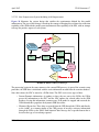
1.5.2 Database Upgrade
The generic JTLS database upgrade feature of the Database Development System (DDS), known as
the JTLS Database Modify process, is accessed by a sequence of three JTLS Menu options: 1.
Prepare or Alter a Scenario Database > 1. Access the Database Development System Menu > 2.
Access an Existing Database. This upgrade feature must be used to upgrade the JTLS Standard
Database from Version 3.1 to Version 3.2.0.0
Oracle Database Server version 9.2.0.8 or later must be used to execute the
Database Modify process while upgrading the JTLS Standard Database from
any previous version to Version 3.2.0.0. The modification process will fail if
performed using earlier Oracle DB versions.
JTLS 3.2.0.0
1-7
Version Description Document
JTLS Document 17
April 2007
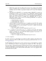
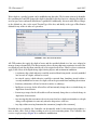
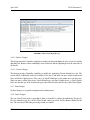
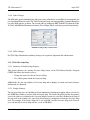
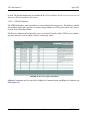
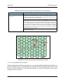
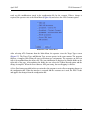
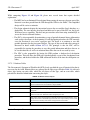
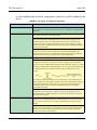
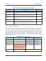
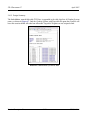
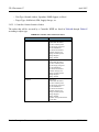
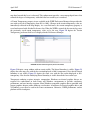
When the user selects and accesses a database that does not conform to the Standard Database 3.2
format, a Warning dialog box (Figure 1.1) queries the JTLS user to begin the upgrade process.
Figure 1.1 Starting the Database Upgrade
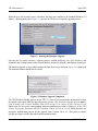
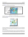
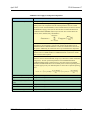
Selecting the Yes option executes a separate process, entitled Modifying Your JTLS Database, that
determines the existing format of the selected database, begins the upgrade, and displays its progress
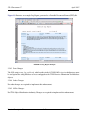
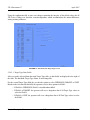
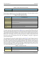
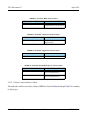
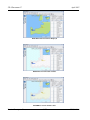
The database upgrade is successfully completed when the message shown in Figure 1.2 is displayed.
The terminal window should then be closed.
Figure 1.2 Database Upgrade Completed
The JTLS Database Modify process for the JTLS 3.1 series of releases includes an interactive feature
that requires user input while the upgrade process executes. This interactive upgrade process must be
used to modify your scenario database from JTLS version 3.0 or earlier to JTLS Version 3.2.0.0.
Ensure that you review the corresponding database modification section of Chapter 1 of the JTLS
Version Description Document for JTLS versions 3.1.0.0, 3.1.1.0, or 3.1.2.0, which describes the
interactive modification process for the upgrade from Version 3.0 to 3.1. This process requires
specific user input, which is described and illustrated in detail.
Version Description Document
1-8
JTLS 3.2.0.0
April 2007
JTLS Document 17
After your database has been modified from Version 3.0 or earlier to Version 3.2.0.0 and downloaded
to ASCII files, a successive scenario load is required to properly create the check constraints in the
database to include the new illegal character set ( space, ", #, &, @, /, {, }, <, >, ’ ). Unit names,
Target names, or other object names that contain any of these characters will be automatically
removed from your database. These symbols are incompatible with the JTLS 3.2.0.0 WHIP.
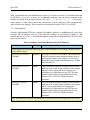
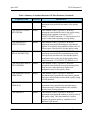
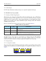
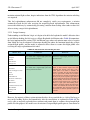
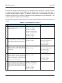
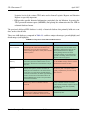
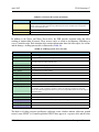
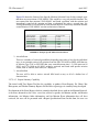
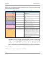
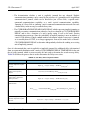
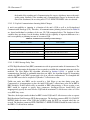
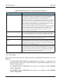
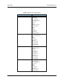
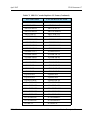
1.5.3 Data Elements
Currently implemented ECPs have required the addition, deletion, or modification of several data
elements. The description and use of the affected variables are presented in Chapter 2 and
summarized below in Table 1. Detailed descriptions are provided in Appendix B of the JTLS Data
Requirements Manual.
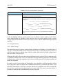
Table 1.Summary of Standard Database OIF Data Elements
VARIABLE NAME
CHANGE
DESCRIPTION
These parameters support the separate graphical representation of Truck, Barge, and Rail convoys
on the WHIP display.
SLP TRUCK CONVOY
SYMBOL
Modified
Formerly SLP CONVOY SYMBOL.This Sustainment
Logistics Prototype entity attribute holds the name of
the Graphic Symbol used to display a Truck Convoy
dispatched from a Support unit belonging to a Faction
that uses this SLP.
SLP BARGE CONVOY
SYMBOL
Added
This Sustainment Logistics Prototype entity attribute
holds the name of the Graphic Symbol used to display
a Barge Convoy dispatched from a Support unit
belonging to a Faction that uses this SLP. This new
attribute will be filled with the symbol held by the
obsolete SLP CONVOY SYMBOL database
parameter
SLP RAIL CONVOY
SYMBOL
Added
This Sustainment Logistics Prototype entity attribute
holds the name of the Graphic Symbol used to display
a Rail Convoy dispatched from a Support unit
belonging to a Faction that uses this SLP.This new
attribute will be filled with the symbol held by the
obsolete SLP CONVOY SYMBOL database
parameter
This data parameter represents the limitations of Towed Array sensors employed by Naval units.
JTLS 3.2.0.0
1-9
Version Description Document
JTLS Document 17
April 2007
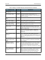
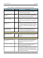
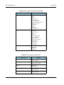
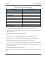
Table 1.Summary of Standard Database OIF Data Elements (Continued)
VARIABLE NAME
ST MAXIMUM SPEED
ALLOWED
CHANGE
Added
DESCRIPTION
This Sensor Type entity attribute holds the maximum
speed at which the ship carrying a sensor of Type I can
be moving and still be able to use the sensor to detect
other assets.
The meaning of this Aircraft Class attribute has been changed as a result of implementing a
reason code for an Air Mission’s intercept termination.
AC CONTINUE ENGAGE
MULT
Modified
This attribute of the Aircraft Class permanent entity is
used to determine whether an attacking aircraft
continues an air-to-air engagement after the first shot is
fired. The data held for this variable should be
reviewed in any database that is upgraded to a JTLS
3.2 format.
This parameter supports the capability of the Interceptor Assignment logic to prevent a Combat
Air Patrol mission from automatically intercepting a specified aircraft target type.
ACP ATC AUTO
INTERCEPT ALLOWED
Added
This variable holds an indicator that signifies whether
the CAP missions from a Faction that uses ACP I can
be automatically sent to intercept a mission that has
aircraft that use ATC J. This data element requires a
new Oracle table, a new initialization data file, and a
new Database Development System (DDS) Air
Control Prototype (ACP) child form.
These parameters support modification of the JTLS Lanchester attrition capability to reduce its
dependence upon the hexagonal terrain model.
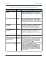
CSP CS FRACTION FAIL
ON ISSUE
Deleted
All references apply to CSP CS PROB NON
COMBAT FAILURE.
CSP CS FRACTION
REPAIRED PER PERIOD
Deleted
All references apply to CSP CS MEAN TIME
BETWEEN REPAIRS.
CSP CS FRACTION
RECOVERABLE
Deleted
All references apply to CSP CS PROB SYSTEM
RECOVERED
CSP FRACTION
REMAINS
RECOVERABLE.
Deleted
All references apply to CSP PROB REMAINS
RECOVERED.
Version Description Document
1-10
JTLS 3.2.0.0
April 2007
JTLS Document 17
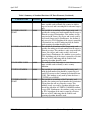
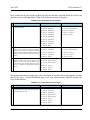
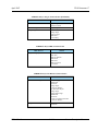
Table 1.Summary of Standard Database OIF Data Elements (Continued)
VARIABLE NAME
CHANGE
DESCRIPTION
MIN TONS CL VII TO
DISTRIBUTE
Deleted
Not used
SP CS PACKET SIZE
Modified
Except for personnel Combat Systems, 1 is a
reasonable value. For personnel, a value between five
and 20 is reasonable.
SP CS HRU PACKET
SIZE
Modified
Typically, this value should be 1.
SP TU UNIT LEVEL
ATTRITION MODERATE
Modified
This variable specifies the fractional loss per hour that
constitutes attrition at a moderate level.
SP TU UNIT LEVEL
ATTRITION SEVERE
Modified
This variable specifies the fractional loss per hour that
constitutes attrition at a severe level.
TUP CS TOE
Modified
This variable represents the number of items of the
Combat System that the Unit is authorized to have on
hand as a integer value.
CSP CS ATTRITION
TYPE
Modified
The new value SHORT-INDIRECT indicates an
indirect fire computation subject to combat power
distribution.
CSP CS SUPPLY USAGE
PER DAY
Modified
This Combat System entity attribute specifies the
amount of supplies that a single Combat System of this
type uses during per day if the unit is in a Lanchester
Battle Set.
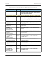
LANCHESTER
COEFFICIENT BASE
TIME
Added
This general modeling parameter holds the time period
for which the Lanchester coefficients in this database
were computed.
MINIMUM ASSESS
COMBAT INTERVAL
Added
This general modeling parameter holds the minimum
time interval during which an Assess Combat will be
conducted and represents the greatest acceptable
period of time to withhold the computation of combat
results.
CSP CS PROB NON
COMBAT FAILURE
Added
This Combat System Prototype, Combat System entity
attribute represents the probability that a Combat
System of this type will be unavailable due to noncombat failure when the unit arrives in the game.
JTLS 3.2.0.0
1-11
Version Description Document
JTLS Document 17
April 2007
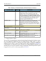
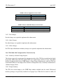
Table 1.Summary of Standard Database OIF Data Elements (Continued)
VARIABLE NAME
CHANGE
DESCRIPTION
CSP CS PROB SYSTEM
RECOVERED
Added
This Combat System Prototype, Combat System entity
attribute represents the probability that a Combat
System loss is recovered and placed into maintenance
for repair.
CSP PROB REMAINS
RECOVERED
Added
This Combat System Prototype, Combat System entity
attribute represents the probability that personnel
Combat Systems are recovered, even though they have
been catastrophically destroyed or Killed In Action.
CSP CS MEAN TIME
BETWEEN FAILURE
Added
This Combat System Prototype, Combat System entity
attribute is the mean of an exponential distribution that
represents the average time between non-combat
failures for a Combat System of this type.
CSP CS MEAN TIME
BETWEEN REPAIR
Added
This Combat System Prototype, Combat System entity
attribute is the mean of an exponential distribution that
represents the average time between repairs for a
Combat System of this type.
These parameters support a capability to enable a single JTLS SSM launcher to fire more than one
Targetable Weapon type.
SSM TARGETABLE
WEAPON
Deleted
Not used
SSM TW CAN FIRE
Added
This indicator signifies whether the SSM is permitted
to fire the specified Targetable Weapon. Database
builders must thoroughly review their SSM target data
and remove any SSMs that were created to provide
their units the capability to fire various Targetable
Weapons.
These parameters support the JTLS logistics consumption algorithm enhancements that track
supply consumption according to the type and number of Combat Systems owned by a particular
unit.
CSP CS NON COMBAT
FUEL USAGE
Version Description Document
Added
This Combat System Prototype, Combat System entity
attribute holds the amount of fuel Combat System J
uses per day when it is owned by a unit belonging to a
faction that uses Combat System Prototype I while the
unit is in a non-combat mode.
1-12
JTLS 3.2.0.0
April 2007
JTLS Document 17
Table 1.Summary of Standard Database OIF Data Elements (Continued)
VARIABLE NAME
CHANGE
DESCRIPTION
CSP CS COMBAT FUEL
USAGE
Added
This Combat System Prototype, Combat System entity
attribute holds the amount of fuel Combat System J
uses per day when it is owned by a unit belonging to a
faction that uses Combat System Prototype I while the
unit is participating in a force-on-force Lanchestrian
battle.
CSP CS FUEL PER KM
Added
This Combat System Prototype, Combat System entity
attribute holds the amount of fuel Combat System J
uses per day when it is owned by a unit belonging to a
faction that uses Combat System Prototype I while the
unit is moving.
SLP UP FUEL
MODIFIER
Added
This Combat System Prototype, Combat System entity
attribute holds the modifier for the amount of fuel a
unit belonging to a Faction that uses Sustainment
Logistics Prototype I while the unit is in posture J.
CSP UP AMMUNITION
MODIFIER
Added
This Combat System Prototype, Combat System entity
attribute holds the modifier for the amount of
ammunition a unit belonging to a Faction that uses
Combat System Prototype I while the unit is in posture
J.
CATEGORY CLASS III
NAVAL
Added
This variable specifies the supply category that is used
for naval movement fuel.
CSP CS AMMUNITION
SUPPLY USAGE
Modified
Formerly CSP CS SUPPLY USAGE PER PERIOD.
This variable specifies the amount of supplies that a
single Combat System of this type uses during one
day, if the owning unit is in combat.
TUP SC USAGE ATTACK
Modified
Formerly TUP SC PER PERIOD USAGE
ATTACK.This variable specifies the rate at which an
attacking Unit consumes the category of supply per
day, which is added to the normal consumption rate
specified in the TUP SC BASIC USAGE attribute if
the Unit is in the ATTACK posture and is in contact
with enemy units.
JTLS 3.2.0.0
1-13
Version Description Document
JTLS Document 17
April 2007
Table 1.Summary of Standard Database OIF Data Elements (Continued)
VARIABLE NAME
CHANGE
DESCRIPTION
TUP SC USAGE
DEFEND
Modified
Formerly TUP SC PER PERIOD USAGE
DEFEND.This variable specifies the rate at which an
attacking Unit consumes the category of supply per
day, which is added to the normal consumption rate
specified in the TUP SC BASIC USAGE attribute if
the Unit is in the DEFEND posture and is in contact
with enemy units.
TUP SC USAGE DELAY
Modified
Formerly TUP SC PER PERIOD USAGE DELAY.
This variable specifies the rate at which an attacking
Unit consumes the category of supply per day, which
is added to the normal consumption rate specified in
the TUP SC BASIC USAGE attribute if the Unit is in
the DELAY posture and is in contact with enemy units.
TUP SC USAGE
WITHDRAW
Modified
Formerly TUP SC PER PERIOD USAGE
WITHDRAW. This variable specifies the rate at which
an attacking Unit consumes the category of supply per
day, which is added to the normal consumption rate
specified in the TUP SC BASIC USAGE attribute if
the Unit is in the WITHDRAW posture and is in
contact with enemy units.
SUP SC USAGE AIR OPS
Modified
Formerly TUP SC PER PERIOD AIR OPS USAGE.
This variable specifies the rate at which a ship
consumes the category of supply while it is in an AIR
OPERATIONS posture, which is added to the normal
consumption rate specified in the SUP SC BASIC
USAGE attribute,
SUP SC USAGE
GUNFIRE
Modified
Formerly TUP SC PER PERIOD GUNFIRE USAGE.
This attribute of the SHIP UNIT PROTOTYPE,
SUPPLY CATEGORY entity specifies the rate at
which a ship consumes the category of supply while it
is reinforcing a land Unit that is involved in
Lanchestrian combat, and is added to the normal
consumption rate specified in the SUP SC BASIC
USAGE attribute.
Version Description Document
1-14
JTLS 3.2.0.0
April 2007
JTLS Document 17
Table 1.Summary of Standard Database OIF Data Elements (Continued)
VARIABLE NAME
CHANGE
SUP SC PER KM USAGE
Modified
DESCRIPTION
This SHIP UNIT PROTOTYPE entity attribute and
specifies the amount of the Supply Category required
to move the unit one kilometer.
These parameters support the C3 representation as a unit capability rather than a Combat System.
CP TIME DELAY PER
100 KM
Deleted
Communications are no longer a function of the
distance between units, and are based solely on the
communication capability of the two units that attempt
contact.
CP JAMMING DELAY
TIME MAX
Deleted
All references apply to CQR JAMMING DELAY
TIME MEAN.
CP JAMMING DELAY
TIME MEAN
Deleted
All references apply to CQR JAMMING DELAY
TIME MEAN.
CP PROB
BACKGROUND
MESSAGE DELAY
Deleted
All references apply to CP CQR PROB MESSAGE
DELAY.
CP COMM JAM ADA
ENGAGE
EFFECTIVENESS
Deleted
All references apply to CP CQR COMM JAM ADA
ENGAGE MULT.
CP COMM JAM
COMBAT
EFFECTIVENESS
Deleted
All references apply to CP CQR COMM JAM
COMBAT MULT.
CP COMM JAM COMM
SITE EFFECTIVENESS
Deleted
All references apply to CP CQR COMM JAM
COMM SITE MULT
CP COMM JAM
INDIRECT FIRE DELAY
FACTOR
Deleted
All references apply to CP CQR COMM JAM FIRE
DELAY MULT.
CP COMM JAM MOVE
DELAY FACTOR
Deleted
All references apply to CP CQR COMM JAM MOVE
DELAY MULT.
CP COMM JAM
INTERNAL TIME
DELAY FACTOR
Deleted
All references apply to CP CQR COMM JAM
INTERNAL MULT.
JTLS 3.2.0.0
1-15
Version Description Document
JTLS Document 17
April 2007
Table 1.Summary of Standard Database OIF Data Elements (Continued)
VARIABLE NAME
CHANGE
DESCRIPTION
COMBAT SYSTEM C3
Deleted
The Combat System specified by COMBAT SYSTEM
C3 will also be removed from the Combat System list
when the Modify program is executed.
CC TYPE
Modified
This variable is an attribute of the Communication
Center entity. CC TYPE (I) holds the function that a
Communications Site target, which has a TG
SUBCATEGORY value of I, will fulfill.
CC DATALINK RANGE
Modified
This attribute is used only if the CC TYPE is
AIR_DEFENSE, and not used for subcategories with
CC TYPE of COMMAND.
CC JAMMING FACTOR
Modified
The message is delayed due to jamming for a period of
time drawn from an exponential distribution with a
mean equal to the value held in the CQR JAMMING
DELAY TIME MEAN attribute of the C3 QUALITY
RATING entity.
CP JAMMING
THRESHOLD
Modified
This attribute is used only if the CC TYPE is
AIR_DEFENSE, and not used for subcategories with
CC TYPE of COMMAND.
TG NUMBER
Modified
The allowable range of values is different for each
target type for which the Target Number attribute is
used. This is a new data field for Communication Site
targets. For type COMMAND, this value represents
the number of percentage points subtracted from the
UT C3 EFFECTIVENESS of the target’s owning or
associated unit when the target is destroyed.
TG ASSOCIATED UNIT
Modified
This attribute of the TARGET entity holds the name of
the unit with which the target is associated. This may
be a unit other than the unit that owns the target.
TG OWNING UNIT
Modified
This attribute of the TARGET entity holds the name of
the owning unit, if assigned, and represents the unit
that determines the target’s Faction, and by extension,
other Faction-related attributes
Version Description Document
1-16
JTLS 3.2.0.0
April 2007
JTLS Document 17
Table 1.Summary of Standard Database OIF Data Elements (Continued)
VARIABLE NAME
CHANGE
DESCRIPTION
CQR NAME
Added
This attribute of the C3 QUALITY RATING
permanent entity holds the text name of the quality
rating.
CQR EFFECTIVENESS
MULTIPLIER
Added
This attribute of the C3 QUALITY RATING
permanent entity holds the value of the quality rating
modifier that is applied to the unit’s UT C3
EFFECTIVENESS when the C3 effectiveness level is
used for other than computing message delays
CQR MINIMUM C3
EFFECTIVENESS
Added
This attribute of the C3 QUALITY RATING
permanent entity holds the minimum value that the
product of the quality rating modifier and the unit’s C3
effectiveness is allowed to be for this quality rating.
CQR MEAN MSG
DELAY HIGHEST HQ
Added
This attribute of the C3 QUALITY RATING
permanent entity holds the exponential mean of the
message delay time between a unit and the highest
headquarters unit on the side for this quality rating
when both units’ UT C3 EFFECTIVENESS is 1.0.
CQR MAX MSG DELAY
NEXT HIGHER
Added
This attribute of the C3 QUALITY RATING
permanent entity holds the maximum message delay
time between a unit and its next higher level
headquarters unit for this quality rating.
CQR JAMMING DELAY
TIME MEAN
Added
This attribute of the C3 QUALITY RATING
permanent entity represents the mean time a jammed
message is delayed when a unit with this quality rating
is being jammed.
CQR JAMMING DELAY
TIME MAX
Added
This attribute of the C3 QUALITY RATING
permanent entity represents the maximum time a
jammed message is delayed when a unit with this
quality rating is being jammed
CQR PRIORITY
Added
This attribute of the C3 QUALITY RATING
permanent entity holds the ranking or priority value of
the quality rating. This data parameter is used to
compare the general quality or capability of two
different CQR objects.
JTLS 3.2.0.0
1-17
Version Description Document
JTLS Document 17
April 2007
Table 1.Summary of Standard Database OIF Data Elements (Continued)
VARIABLE NAME
CHANGE
DESCRIPTION
CQR NEXT LOWER
QUALITY RATING
Added
This attribute of the C3 QUALITY RATING
permanent entity holds the name of the CQR object
that should be assigned to a unit when the unit’s UT
C3 EFFECTIVENESS becomes zero
CQR LOWER RATING
EFFECTIVENESS
Added
This attribute of the C3 QUALITY RATING
permanent entity holds the initial value of the unit’s
UT C3 EFFECTIVENESS after the unit is assigned
the new lower quality rating because the unit’s UT C3
EFFECTIVENESS is equal to zero.
CQR NEXT HIGHER
QUALITY RATING
Added
This attribute of the C3 QUALITY RATING
permanent entity holds the name of the CQR object
that should be assigned to a unit when the unit’s UT
C3 EFFECTIVENESS value exceeds 1.0. An SVP
check is added to ensure that the CQR PRIORITY is
consistently assigned.
CQR HIGHER RATING
EFFECTIVENESS
Added
This attribute of the C3 QUALITY RATING
permanent entity holds the initial value of the unit’s
UT C3 EFFECTIVENESS after the unit is assigned
the new higher quality rating because the unit’s UT C3
EFFECTIVENESS value exceeds 1.0.
CQR HIGHER RATING
EFFECTIVENESS
Added
This attribute of the C3 QUALITY RATING
permanent entity holds the initial value of the unit’s
UT C3 EFFECTIVENESS after the unit is assigned
the new higher quality rating because the unit’s UT C3
EFFECTIVENESS value exceeds 1.0.
CQR C3 LOSS MULT
Added
This attribute of the C3 QUALITY RATING
permanent entity holds the portion of the unit’s
weighted unit strength loss that is subtracted from the
unit’s UT C3 EFFECTIVENESS.
The Communication Prototype (CP) entity already exists in the initialization database. A new
sub-entity table is added to hold data required for each CP and CQR combination.
CP CQR PERCENT
RECOVERED PER DAY
Version Description Document
Added
This attribute of the Communications Prototype, C3
Quality Rating compound entity holds the percent of
C3 effectiveness that a unit can recover in one day.
1-18
JTLS 3.2.0.0
April 2007
JTLS Document 17
Table 1.Summary of Standard Database OIF Data Elements (Continued)
VARIABLE NAME
CHANGE
DESCRIPTION
CP CQR PROB
MESSAGE DELAY
Added
This attribute of the Communications Prototype, C3
Quality Rating compound entity represents the
probability that a message sent by a unit is delayed.
CP CQR COMM JAM
ADA ENGAGE MULT
Modified
This variable is an attribute of the Communications
Prototype, C3 Quality Rating compound entity. The
quality rating referenced is the CQR of the unit that is
being jammed and attempting to engage.
CP CQR COMM JAM
COMBAT MULT
Modified
This variable is an attribute of the Communications
Prototype, C3 Quality Rating compound entity. The
referenced quality rating is the CQR of the attriting
unit.
CP CQR COMM JAM
COMM SITE MULT
Modified
This variable is an attribute of the Communications
Prototype, C3 Quality Rating compound entity. This
factor is a measure of the Faction’s susceptibility to
communications jamming when the owning unit of the
COMM SITE has the referenced quality rating.
CP CQR COMM JAM
FIRE DELAY MULT
Modified
This variable is an attribute of the Communications
Prototype, C3 Quality Rating compound entity. The
communications prototype referenced is the CP of the
unit firing the mission. The referenced quality rating is
the CQR of the unit that is being jammed and is firing
the mission
CP CQR COMM JAM
INTERNAL MULT
Modified
This variable is an attribute of the Communications
Prototype, C3 Quality Rating compound entity. The
referenced communications prototype is the CP of the
unit conducting the task. The referenced quality rating
is the CQR of the unit conducting the task.
CP CQR COMM JAM
MOVE DELAY MULT
Modified
This variable is an attribute of the Communications
Prototype, C3 Quality Rating compound entity. The
communications prototype referenced is the CP of the
unit conducting the move. The quality rating
referenced is the CQR of the unit conducting the
move.
JTLS 3.2.0.0
1-19
Version Description Document
JTLS Document 17
April 2007
Table 1.Summary of Standard Database OIF Data Elements (Continued)
VARIABLE NAME
CHANGE
DESCRIPTION
UT C3 EFFECTIVENESS
Added
This variable is an attribute of the Unit entity, and
holds the current effectiveness level of a unit’s
Command and Control capability.
UT C3 QUALITY
RATING
Added
This variable is an attribute of the Unit entity, and
holds the name of the C3 QUALITY RATING that this
unit is assigned when it arrives in the game.
UT HIGHEST C3
QUALITY RATING
Added
This variable is an attribute of the Unit entity, and
holds the name of the highest possible C3 QUALITY
RATING to which this unit may be set during the
game.
HUP C3 QUALITY
RATING
Added
This variable is an attribute of the High Resolution
Unit Prototype entity, and holds the name of the HRU
C3 QUALITY RATING that should be assigned to an
HRU that uses this HUP when the HRU is initially
created.
HUP STARTING C3
EFFECTIVENESS
Added
This variable is an attribute of the High Resolution
Unit Prototype entity, and holds the initial C3
effectiveness level of an HRU that uses this HUP.
This parameter replaces a graphic symbol as the identifier of a TUP’s special capability.
TUP CAPABILITIES
TYPE
Added
This attribute of the Tactical Unit Prototype permanent
entity holds the name value of the TUP’s special
capability.
These parameters were added or modified to support JOI improvements related to TADIL-J.
ACP AIR INFORMATION Modified
PROTOCOL
This variable is an attribute of the AIR CONTROL
PROTOTYPE permanent entity and specifies the
protocol for sharing real-time air detection
information.
AC LINK16 CAPABLE
Added
SUP SHIP CLASS NAME
Added
This Aircraft Class permanent entity attribute indicates
whether the aircraft class is linked to the side’s
Common Operational Picture (COP).
This variable is an attribute of the Ship Unit Prototype
permanent entity that holds the name the SUP’s Ship
Class, and is specifically required to properly link to
real-world C4I systems, such as the Global Command
and Control System (GCCS).
Version Description Document
1-20
JTLS 3.2.0.0
April 2007
JTLS Document 17
Table 1.Summary of Standard Database OIF Data Elements (Continued)
VARIABLE NAME
CHANGE
TG COUNTRY CODE
Added
TG LINK16 BLOCK
START
Added
TG LINK16 BLOCK END
Added
UT COUNTRY CODE
Added
UT HULL NUMBER
Added
UT LINK16 BLOCK
START
Added
JTLS 3.2.0.0
DESCRIPTION
This attribute of the Target entity is a two-character text
name variable used to identify the country in which a
target is located, and is meaningful for unowned targets
only.
This variable is an attribute of the Target entity, and
specifies the starting octal track number that the target is
allowed to assign. Relationships: This attribute is only
associated with Sensor_Site targets and is only used by
Air Search Sensor targets. Furthermore, the attribute is
only access by JTLS algorithms if the target is owned by
a Faction that uses an ACP indicating that the Link16
track reporting algorithm should be used.
This variable is an attribute of the Target entity, and
specifies the ending octal track number that the target is
allowed to assign. This attribute is only associated with
Sensor_Site targets and is only used by Air Search
Sensor targets. Furthermore, the attribute is accessed by
JTLS algorithms only if the target is owned by a Faction
that uses an ACP indicating that the Link16 track
reporting algorithm should be used.
This attribute of the Unit entity is a two-character text
name variable used to identify a unit s country
affiliation.
This variable is a text attribute of a Unit entity, and
holds the hull number that should be reported to realworld C4I systems or the Common Operational Picture
(COP). This attribute is only used by units that have a
UT TYPE set to NAVAL.
This variable is an attribute of the Unit entity, and
specifies the starting octal track number that air mission
s flying from the unit are allowed to assign. This
attribute is only accessed by Squadron units that own
aircraft for which the AC LINK16 CAPABLE attribute
is set to YES. Furthermore, the attribute is only accessed
by JTLS algorithms if the unit is owned by a Faction
that uses an ACP indicating that the Link16 track
reporting algorithm should be used.
1-21
Version Description Document
JTLS Document 17
April 2007
Table 1.Summary of Standard Database OIF Data Elements (Continued)
VARIABLE NAME
CHANGE
UT LINK16 BLOCK END
Added
UT PIFF CODE
Added
DESCRIPTION
This variable is an attribute of the Unit entity, and
specifies the starting octal track number that air mission
s flying from the unit are allowed to assign. This
attribute is only accessed by Squadron units that own
aircraft for which the AC LINK16 CAPABLE attribute
is set to YES. Furthermore, the attribute is only accessed
by JTLS algorithms if the unit is owned by a Faction
that uses an ACP indicating that the Link16 track
reporting algorithm should be used.
This variable is an attribute of a Unit entity and
represents the octal code output of a ship’s Passive
Identification of Friend or Foe (PIFF) apparatus. This
attribute applies only to units that have a UT TYPE of
NAVAL.
This unused parameter is removed from the database.
MAX FIRE MISSION
Deleted
Not Used
DURATION
The set of restricted characters for all text variable values is redefined.
General
Modified The characters #, &, $, @, /, {, }, <, >, ’, and embedded
spaces are prohibited.
UT LONG NAME
Modified The characters #, &, $, @, /, {, }, <, >, and ’ are
prohibited. Embedded spaces are allowed.
SUP SHIP CLASS NAME Modified The characters #, &, $, @, /, {, }, <, >, ’, and - are
prohibited. Embedded spaces are allowed.
1.5.4 Standard Database Changes
The new JTLS 3.2 Standard Database based on Operation Iraqui Freedom (sdboif) includes extensive
data item modifications implemented since the Standard Database (SDB) version 3.1 (sdbv31)
release. If you have used sdbv31 as a basis for your existing scenarios, evaluating the modifications
included in sdboif is advised. A total of 99 Combat Systems, which are described in APPENDIX B.
of this document, are represented in sdboif. Reviewing your existing SDB-derived databases and
upgrading them to the new data standard is strongly recommended. The detailed procedures required
to upgrade sdbv30 or sdbv31 to sdboif are provided in APPENDIX C.
Version Description Document
1-22
JTLS 3.2.0.0
April 2007
JTLS Document 17
1.6 INSTALLATION NOTES
1.6.1 Installation Instructions
The JTLS Installation Manual (included in the documents compressed tar file that is part of this JTLS
release) provides detailed instructions for installing a new version of JTLS.
1.6.2 Oracle Compatibility and Installation
This release of JTLS requires a complete installation of Oracle Forms/Reports Developer 6i client/
server runtime.
Developer 6i is the final version of the client/server development and deployment of Oracle Forms,
Reports, and Graphics. Oracle Corporation will provide only limited support for this Developer
version until January 2008, and Oracle10g will become the final certified database server compatible
with Developer 6i. Beginning with the release of JTLS 3.1.0.0, Oracle 10g iAS EE (Internet
Application Server Enterprise Edition) has been implemented to deploy JTLS database applications,
such as DDS Forms. The compatible database server version is Oracle 10gR2 Standard Edition One
or newer. Database server requirements that are updated prior to a future JTLS release will be
described in the appropriate JTLS Version Description Document.
Utilizing the framework of iAS EE, which includes Forms Services, Reports Services, Portal, Single
Sign-On, Java, and other components, will enable the delivery of JTLS-specific data from a central
location. This also allows the development of more scalable JTLS database applications, such as the
SDR and AAR.
Currently, the following combinations of Forms 6i runtime and the Oracle Server are approved for use
with JTLS:
a. Oracle Database Server 9.2.0.8 or later (10gR2 Standard Edition One is recommended)
b. Forms 6i client/server runtime (with patchset 18 or later) for Solaris and/or Linux
c. iAS EE 10.1.2.0.2 full stack (optional)
Refer to Chapter 6 of the JTLS Installation Manual for additional details regarding the Oracle Forms/
Reports Developer 6i client/server custom runtime installation.
JTLS 3.2.0.0
1-23
Version Description Document
JTLS Document 17
Version Description Document
April 2007
1-24
JTLS 3.2.0.0
April 2007
JTLS Document 17
2.0 ENHANCEMENT CHANGE PROPOSALS
JTLS 3.2.0.0 is a Major JTLS release that includes the implemented Enhancement Change Proposals
(ECPs) described in this chapter.
2.1 JTLS-0004 Display Range Rings
2.1.1 Summary of Model Change Request
This design addresses a requirement to graphically display range data for units, targets, and Air
Missions on the Web Hosted Interface Program (WHIP) Map Component.
2.1.2 Design Summary
JTLS object types for which Range Rings have been added to the WHIP are described in Table 2.
TABLE 2. Range Ring Object Types
OBJECT TYPE
EXPLANATION
CANDIDATE DATA
Squadron
Aircraft Range Radius
The flight radius of the standard fuel load for aircraft flying from this
Squadron while the mission flies at its cruise speed and at the most fuelefficient altitude. If the aircraft has a database-specified default load, the fuel
from that default load is also considered in the range computation. The flight
radius is determined by computing the range of the aircraft under the
specified conditions and dividing by 2.0.
Support
Min or Max Distance
For Truck Convoys
The database values for the minimum or maximum range to which the
Support unit sends convoy trucks.
FARP
Ground
Naval
Direct Weapon Range
The range of the longest manned Direct Fire Combat System that the unit
owns. As the unit loses systems or crews to operate those systems, this range
is adjusted. Supplies are considered for this computation. If the unit has no
supplies available for this Combat System to fire, the range is listed as zero.
Indirect Weapon Range
The range of the longest-range weapon that can be fired from the unit’s
manned Indirect Fire Combat Systems, considering the unit’s caliber and
available supplies. As the unit loses systems or crews, or consumes supplies
to operate those systems, this range is adjusted.
Due to the implementation of the ECP JTLS-2006-1660 Integerized
Lanchestrian Combat, a third Combat System type is added to the model.
This new LONG-INDIRECT system type is also used to compute this range.
Thus, this range represents the longest manned Combat System that has a
type of INDIRCT or LONG-INDIRECT.
Mandatory Transfer
Distance
The distance at which mandatory transfers of supplies can occur. This range
is adjusted only if the Controller changes this database parameter.
JTLS 3.2.0.0
2-1
Version Description Document
JTLS Document 17
April 2007
TABLE 2. Range Ring Object Types (Continued)
OBJECT TYPE
EXPLANATION
CANDIDATE DATA
High Resolution Unit
(HRU)
Weapons Range
The range of the HRU’s longest-range combat system for which it has
required ammunition. As the HRU uses ammunition or loses Combat
Systems, this range is adjusted. HRUs that represent Non-Government
Organizations (NGOs) and other charity organizations may not have Combat
Systems. The ranges specified for these HRUs are zero.
Air Mission
Surface Weapons Range The range of the mission’s longest Air-to-Ground weapon. As munitions are
expended, the range is adjusted.
Air Weapons Range
The range of the mission’s longest Air-to-Air weapon. As munitions are
expended, the range is adjusted.
Surface Sensor Range
The range of the mission’s longest-range activated Surface Search sensor.
The model determines when JTLS Air Search radars are activated. If no
sensors are activated, the range is zero.
Air Sensor Range
The range of the longest-range activated Air Search sensors that are activated
according to the same criteria described for Surface Sensor Range.
Target:
ADA
Allowed Firing Range
by Altitude Zone
Air Defense Artillery (ADA) targets have database range data for each
Altitude Zone represented in the database. The range of the two weapons
associated with each ADA type does not affect the capability of the ADA site
within JTLS, and therefore is used to provide range information to the
WHIP.
On the other hand, the database parameter called TG RANGE limits the
database ADA prototype altitude-based range data. This limiting factor is
considered when the firing range array data are passed to the JTLS Object
Distribution Authority (JODA).
Target: Communications
Site
Communications Range
Communications targets have a range over which they can communicate
with Airborne Warning and Control System (AWACS) aircraft. Any enemy
targets detected by an AWACS mission within range of an AIR DEFENSE
Communications Site target is automatically processed using the Integrated
Air Defense System (IADS) to which the Communications Site is linked.
This range is displayed for these Communications Site targets.
Communications Site targets of type COMMAND do not have an associated
range. Their ranges are specified as equal to zero.
Target:
Jammer
Jammer Range
The minimum of the range of the Jammer represented by the target (JT
RANGE) and the limiting range of the target (TG RANGE). Although this
range is the maximum range at which the target is able to jam the
communications of units or enemy radars, not all objects within the range are
jammed. Like the Air Mission objects discussed previously, the actual
jamming range is a function of the power of the enemy capability being
jammed.
Version Description Document
2-2
JTLS 3.2.0.0
April 2007
JTLS Document 17
TABLE 2. Range Ring Object Types (Continued)
OBJECT TYPE
EXPLANATION
CANDIDATE DATA
Target:
SSM Site
Weapons Range
The obvious choice for a Surface-to-Surface Missile (SSM) target is the
range of the weapon that the site is allowed to fire. A JTLS SSM site can fire
only one type of weapon; thus, only one range would be necessary. A
planned JTLS improvement will enable SSM sites to fire several types of
weapons that may have different range capabilities, which implies a
requirement to associate several ranges, or an array of ranges, with each
SSM type. This approach is problematic because the number of weapons that
can be fired by the SSM is variable and can change as the exercise
progresses. This is different than the capability of ADA targets, for which the
number of Altitude Zones is fixed for a given scenario.
Target:
Sensor Site
Allowed Sensor Range
by Altitude Zone
Available data for JTLS Air Search sensors and Surface Search sensors are
different.
Surface Search sensors, similar to Jammers, have a range limited by the
minimum of the range of the sensor represented by the target (ST RANGE)
and the limiting range of the target (TG RANGE). This value is available to
the WHIP for Range Ring representation.
Although Air Search sensors have only a single ST RANGE value limited by
the target TG RANGE, the radar horizon effectively limits this range if the
sensor is not Over the Horizon (OTH) capable. Thus, range data associated
with Air Search sensors are determined by Altitude Zone; the model
computes the range of the sensor, Limited by the radar horizon at the
midpoint within each Altitude Zone, the model computes the range of the
sensor and considers the height of the radar as specified in the database. If
the sensor is OTH capable, the ranges within each Altitude Zone are
identical, but all other Air Search sensor targets have different ranges.
2.1.2.1 Range Ring Display Management
Range Rings are displayed for an object only when the object is visible. Range Ring filters are saved
with the existing set of filters when a user saves a view or the filters. Since the Range Ring filters are
saved with the existing filters, the Range Ring filter can be shared with other Players.
Range Rings are displayed for an object only when the object is visible. Range Ring filters are saved
with the existing set of WHIP display filters when a user saves a Map view or a desired filter
configuration. Since the Range Ring filters are saved with the existing filters, any Range Ring display
configuration created by a user can be shared with other Players.
Users can access the Range Ring interface features by means of the WHIP Map Component filters.
Four new filter panels are added: a general Range Ring filter panel, and separate Range Ring panels
for ADA, Sensors, and SSMs., which are required to accommodate the characteristic data differences
among these object types. Additionally, an On Demand Rings filter panel is provided to create a
customized list and view of various Range Ring types directly from the Map display. The JTLS WHIP
Training Manual included within the JTLS 3.2.0.0 documentation suite provides a detailed
description of the procedures for using these Range Ring capabilities.
JTLS 3.2.0.0
2-3
Version Description Document
JTLS Document 17
April 2007
2.1.3 Data Changes
No database changes are required to implement this enhancement.
2.1.4 Order Changes
No order changes are required to implement this enhancement.
2.1.5 JODA Changes
No JTLS Object Distribution Authority changes are required to implement this enhancement.
2.2 JTLS-0008 Real Time Intercept Report
2.2.1 Summary of Model Change Request
Prior to this change, JTLS user only knew that an Air Mission had begun to intercept a foreign
detected mission by viewing the posture of the mission by means of the Information Management
Terminal (IMT) or Map Component of the Web Hosted Interface Program (WHIP). An air-to-air
engagement was indicated when the Player received a Pilot Trouble Report conveying information
that would typically be provided by a voice message from an aircraft commander.
In 2005, the JTLS air-to-air engagement logic was modified to represent the events of Mission A
firing on Mission B and Mission B returning fire to Mission A as independently scheduled events.
Consequently, the Controller and Player lost the ability to easily track the results of air-to-air
engagements. Several reports, generated after each firing event, had to be manually combined by the
Player or Controller to obtain detailed information regarding the results of a specific engagement.
This model enhancement provides reporting capabilities that replace this process.
2.2.2 Design Summary
This enhancement implements a new mission damage Summary Report that delivers air-to-air
engagement information to Players and Controllers. JTLS internally retains historical engagement
information for each Air Mission. After each engagement, a report of the current engagement and all
previous engagements for a specific Air Mission is placed in a message. Additional engagement
tracking options included using interim mission reports and the new JTLS After Action Review
capability must developed under a separate ECP.
Version Description Document
2-4
JTLS 3.2.0.0
April 2007
JTLS Document 17
The new Engagement Summary report is not limited to air-to-air engagements, but also includes a list
all surface-to-air engagements against the aircraft. Table 3 describes the data held for each
engagement.
TABLE 3. Information Held for Each Engagement
AIR-TO-AIR ENGAGEMENT
SURFACE-TO-AIR ENGAGEMENT
Time of engagement
Time of engagement
Name of firing object
Name of firing object
Side of firing object
Side of firing object
Type of firing object, designated as the aircraft class of the firing
object
Type of firing object, designated as the sub-category of the firing
object
Latitude and longitude of the firing object
Latitude and longitude of the firing object
Altitude of the firing object
Name of the receiving Air Mission
Name of the receiving Air Mission
Side of the receiving object
Side of the receiving object
Type of receiving object, designated as the aircraft class of the
receiving object
Type of receiving object, designated as the aircraft class of the
receiving object
Altitude of the receiving object
Altitude of the receiving object
Type of weapon fired
Type of weapon that is fired
Number of weapons fired
Number of weapons fired
Distance between the engaging objects
Distance between the engaging objects
Probability of Hit
Probability of Hit
Random variate drawn
Random variate drawn
Hit or No Hit identifier
Hit or No Hit identifier
Probability of Kill; equal to zero if no hit occurs
Probability of Kill; equal to zero if no hit occurs
Number of aircraft killed
Number of aircraft killed
Two separate Engagement Summary Reports pertaining to the firing object and the receiving Air
Mission are generated when an engagement occurs. These reports replace the Controller’s Air
Combat Report and the Surface-to-Air Damage Report, and are generated only if the Controller Air
Damage Report flag is set to YES. Table 4 describes the contents of these Summary Reports.
JTLS 3.2.0.0
2-5
Version Description Document
JTLS Document 17
April 2007
TABLE 4. Engagement Summary Report Content
OBJECT PERSPECTIVE
REPORT
AFTER AIR-TO-AIR ENGAGEMENT
AFTER SURFACE-TO-AIR ENGAGEMENT
Firing Object Report
The report lists all of the firing Air Mission’s
engagements. As the Air Mission progresses,
the summary report accumulates records. When
the mission completes, a final Controller
engagement report is generated.
The report lists all of the firing SAM Site
engagements. As time passes, this report will
accumulate records. The existing SAM site
engagement records for the reporting Side are
cleared when a Side’s Summary Report event
executes. A final Summary Engagement report
is not sent when the engagements are cleared.
The new AAR tool is the appropriate source for
a long-term SAM site firing history. Therefore,
generating these reports unnecessarily burdens
the system and the IC with information that
may not be desired.
Receiving Object Report
The report will lists all of the receiving Air
Mission’s engagements from the start of the
mission and in the same manner as previously
described. The mission’s final Summary Report
includes all of its engagements, whether they
were generated as a result of the Air Mission in
the role of the firing object or the receiving
object.
The report lists all of the receiving Air
Mission’s engagements from the start of the
mission and in the same manner as previously
described.
This report contains PK values and the dawn random variate, but is made available as a broadcast
message to all Players involved in the engagement. The Sides that have access to a copy of this
generated message are summarized in Table 5. Provided with the detailed content of this message,
the Player may deliver selected information to the exercise audience.
TABLE 5. Message Delivery Information
OBJECT PERSPECTIVE
REPORT
Firing Object Report
Receiving Object Report
AFTER AIR-TO-AIR ENGAGEMENT
AFTER SURFACE-TO-AIR ENGAGEMENT
Controller and the Side that owns the firing Air
Mission
Controller and the Side that owns the firing
SAM site
Air Function
Ground function if the SAM site is owned by a
ground unit or Naval function if the SAM is
owned by a naval unit
Controller and the Side that owns the receiving
Air Mission
Controller and the Side that owns the receiving
Air Mission
Air Function
Air Function
Version Description Document
2-6
JTLS 3.2.0.0
April 2007
JTLS Document 17
The possible values for the result of each stochastic hit and kill determination are summarized in
Table 6.
TABLE 6. Possible Hit/Kill Values Reported
HIT RESULTS
KILL RESULTS
Hit - The mission was hit.
Kill - One aircraft in the mission was killed by the weapon.
No Hit - The mission was not hit
No Kill - The weapon did not kill the aircraft.
Impossible - The weapon did not hit the aircraft; no kill determination was made.
Undetermined - JTLS does not know the effect of the weapon fired on the aircraft, since the
Air Mission is externally controlled. The model that owns the aircraft must report the results.
To supplement the automatically-generated reports for each engagement, the Player is able to request
the status of the Engagement Summary for Air Missions and Air Defense sites. The JTLS MISSION
REPORT order is altered to include a new field that allows the use to request a mission engagement
report instead of a squadron mission Summary Report. The JTLS user may also request the current
Engagement Summary for an Air Defense site or a group of sites by means of a field added to the Air
Defense Status report. If the Include Engagement Results flag is set, the generated report includes the
engagement information for each Air Defense site. The engagements reported include only those
engagements fired since the previous Periodic Summary. The AAR tool must be utilized to generate
reports to reflect prior engagements.
The existing Pilot Trouble Report capability is not modified or removed; whether these limited
information messages should be viewed or passed to the exercise audience is left to user discretion.
The Controller air-to-air engagement and surface-to-air engagement messages are removed and
replaced by the Engagement Summary messages previously described.
Since the new AAR has all of the same information readily available, three new queries, described in
Table 7, were developed and added to the AAR toolkit.
TABLE 7. New AAR Query Description
QUERY TITLE
USER INPUT
Detailed Mission Engagement Report
Full Mission Name - Mandatory
Detailed ADA Engagement Report
Start Time - Optional - If not entered, assumed to be the start of the game.
End Time - Optional - If not entered, assumed to be the current game time.
Name of ADA Site - Mandatory
Detailed Unit ADA Engagement Report
Start Time - Optional - If not entered, assumed to be the start of the game.
End Time - Optional - If not entered, assumed to be the current game time.
Name of ADA Site - Mandatory
Subordinate Flag - Mandatory - an indicator whether ADA sites for this unit
or this unit and subordinates should be generated.
JTLS 3.2.0.0
2-7
Version Description Document
JTLS Document 17
April 2007
2.2.3 Data Changes
No data changes are required to implement this enhancement.
2.2.4 Order Changes
The Mission Report order is modified to allow the Controller or Player to specify the name of an Air
Mission for which an Engagement Summary message is desired.
The Air Defense Status order is modified to allow the Controller or Player to specify whether the
status report will include Air Defense engagement information.
2.2.5 JODA Changes
No JTLS Object Distribution Authority changes are required to implement this enhancement.
2.3 JTLS-0018 Naval Fuel Usage
2.3.1 Summary of Model Change Request
The design for this model enhancement is included in the more comprehensive fuel design also
implemented as part of JTLS 3.2.0.0. This ECP, JTLS-2006-1752 Improve Fuel Usage Flexibility,
includes the improvements implemented for Ground unit as well as Naval unit fuel consumption.
2.3.2 Design Summary
The logic used for this enhancement is included in JTLS-2006-1752 Improve Fuel Usage
Flexibility.
2.3.3 Data Changes
The data changes required to implement this capability are included in JTLS-2006-1752 Improve
Fuel Usage Flexibility.
2.3.4 Order Changes
The required order changes are included in JTLS-2006-1752 Improve Fuel Usage Flexibility.
2.3.5 JODA Changes
The required JTLS Object Distribution Authority changes are included in JTLS-2006-1752 Improve
Fuel Usage Flexibility.
Version Description Document
2-8
JTLS 3.2.0.0
April 2007
JTLS Document 17
2.4 JTLS-0056 Improve Aircraft Divert Logic
2.4.1 Summary of Model Change Request
Previously, a JTLS Air Mission returning to its home Airbase attempted to find a logical alternative
landing location if the home base runway had been damaged to the extent that the mission could not
land. The model’s runway selection logic considered the following assets in priority order:
1. The user-specified alternate Airbase
2. An Airbase that has a usable runway and available parking spaces for which mission has
enough fuel to reach
3. An unoccupied runway that is long enough to support the mission’s aircraft and for which
the mission has enough fuel to reach
The model neither attempted to locate an alternative landing site nearest the mission’s assigned home
base, nor considered whether the alternative location supported similar aircraft, nor whether it had
available aviation fuel or weapons. This model enhancement has established a more robust automatic
divert location selection logic.
2.4.2 Design Summary
When a mission returns to its home base and cannot land, the new divert logic is executed. The first
condition of this logic establishes whether an alternative location is minimally acceptable. The
following rules were previously applied to this determination, and have not been changed due to
implementing this design:
•
The mission must be able to reach the location, considering its current fuel load.
•
If the alternative is a Naval unit, the Air Mission must be naval-qualified.
•
If the Air Mission requires a runway, the runway at the alternative location must be long
enough for the mission to land.
•
The alternative location must have enough available parking spaces to accommodate the Air
Mission. This check is implemented primarily to prevent all returning aircraft from
selecting the same alternative landing location when a major base is closed.
The model logic first considers the user-assigned alternative base. If this location is feasible, the
model selects the location and the Air Mission is immediately diverted. If this alternative is not
feasible or the user has not assigned an alternative base, the new automatic selection logic is executed.
This new logic does not automatically select the first identified feasible location, but requires the
model to consider all feasible locations. The logic is based on a point system for which a numerical
value is assigned to each feasible location according to its suitability for the mission. The alternative
location that is assigned the greatest point value is selected. In the case of a point value tie between
two locations, the nearest alternative location is selected.
JTLS 3.2.0.0
2-9
Version Description Document
JTLS Document 17
April 2007
Table 8 summarizes the point values that can be assigned to a divert landing location.
TABLE 8. Divert Location Point Assignment Values
ALTERNATIVE CHARACTERISTIC
POINT VALUE
The Airbase or Naval unit is a feasible divert location.
1.0
The location has other squadrons with the same type of aircraft as the diverting mission.
1.0
The location has available fuel to enable at least one aircraft to take off again.
0.5
The location has weapons typically used by the Air Mission. This is determined by reviewing the list of
weapons that were originally loaded on the mission and determining whether the location being
considered has at least one such weapon available. For each weapon that can be supported by a Supply
Category at the base, the location is assigned 0.01 points. Thus, an Airbase with three of the required
weapons supported by supplies will be assigned a point value of 0.03, but a location with only two
weapons stocked in supply will be assigned a point value of 0.02. The Airbase with three stocked
weapons will have priority over an Airbase with two stocked categories.
0.01 per weapon
supported by a
Supply Category
0.01
The location is Unsupported (i.e., the runway is unused).
Consider the examples presented in Table 9. Alternative 4, highlighted green, is selected; its point
value is equal to Alternative 2, but its location is 100 KM closer.
TABLE 9. Example Location Point Value
ID
ALTERNATIVE LOCATION CHARACTERISTICS
1
The Airbase has similar aircraft, but no fuel or weapons are
currently available.
2
The Airbase has similar aircraft, fuel, but no weapons.
3
The Airbase has fuel and two needed weapon supplies, but no
similar aircraft.
4
The Naval unit has similar aircraft, fuel, but no weapons.
5
The runway is abandoned.
COMPUTED POINT VALUE
DISTANCE
1.0 + 1.0 = 2.0
100 KM
1.0 + 1.0 + 0.5 = 2.5
125 KM
1.0 + 0.5 + 0.02 = 1.52
50 KM
1.0 + 1.0 + 0.5 = 2.5
25 KM
0.01
5 KM
2.4.3 Data Changes
No data changes are required to implement this enhancement.
2.4.4 Order Changes
No order changes are required to implement this enhancement.
2.4.5 JODA Changes
No JTLS Object distribution Authority changes are required to implement this design.
Version Description Document
2-10
JTLS 3.2.0.0
April 2007
JTLS Document 17
2.5 JTLS-0074 Refuel Base Logic Improvement
2.5.1 Summary of Model Change Request
When an Air Mission needs fuel and it is heading home, the mission should always give priority to its
home base and not the closest source of fuel.
2.5.2 Design Summary
The logic specified in the ECP was implemented.
2.5.3 Data Changes
No data changes were required for this improvement.
2.5.4 Order Changes
No order changes were required for this improvement.
2.5.5 JODA Changes
No JODA data structure changes were required for this improvement.
2.6 JTLS-0075 Passive Sonars Do Not Detect Surface Ships
2.6.1 Summary of Model Change Request
The previous JTLS naval detection capability representation is summarized in Table 10. Note that the
terms Surface and Sub-surface are used instead of referring to a Naval unit as a surface vessel or a
submarine. This reflects an element of the JTLS detection algorithm; a submarine in shallow water is
considered to be on the surface and will be detected using the Surface vessel algorithms.
TABLE 10. Previous JTLS Ship Detection Capability Representation
ATTEMPTS TO DETECT NAVAL UNIT OF TYPE
OBJECT TYPE
SURFACE
SURFACE NAVAL
UNIT
JTLS 3.2.0.0
SUB-SURFACE
Within the same hex: 100% Probability of Detection
(PD)
Within the same hex: Not considered
Within the same formation: 100% PD
Within the same formation: 100% PD
Surface Search Sensor: PD of all operating sensors
covering the object.
Surface Search Sensor: Not considered
Active Sonar: PD of all operating sensors covering
the object with sufficient reflected power.
Active Sonar: PD of all operating sensors covering
the object with sufficient reflected power.
2-11
Version Description Document
JTLS Document 17
April 2007
TABLE 10. Previous JTLS Ship Detection Capability Representation (Continued)
ATTEMPTS TO DETECT NAVAL UNIT OF TYPE
OBJECT TYPE
SURFACE
SURFACE NAVAL
UNIT
(CONTINUED)
SUB-SURFACE
NAVAL UNIT
AIR MISSION
SUB-SURFACE
Passive Sonar: Not considered
Passive Sonar: Reduce time to detection if covered
object generates sufficient noise
Within same hex: 100% PD
Within same hex: Not considered
Within same formation: 100% PD
Within same formation: 100% PD
Surface Search Sensor: PD of all operating sensors
covering the object.
Surface Search Sensor: Not considered
Active Sonar: PD of all operating sensors covering
the object with sufficient reflected power.
Active Sonar: PD of all operating sensors covering
the object with sufficient reflected power.
Passive Sonar: Not considered
Passive Sonar: Reduce time to detection if covered
object generates sufficient noise
Within same hex, PD
Within same hex: Not considered
Shadowing: 100% PD
Shadowing: 100% PD
Surface Search Sensor: PD of all operating sensors
covering the object.
Surface Search Sensor: Not considered
Active Sonar: PD of all operating sensors covering
the object with sufficient reflected power.
Active Sonar: PD of all operating sensors covering
the object with sufficient reflected power.
Passive Sonar: Not considered
Passive Sonar: Reduce time to detection if covered
object generates sufficient noise
To assist interpreting the previous table, Table 11 defines specific terms referenced in the detection
representation summary.
TABLE 11. Detection Term Definitions
TERM
DEFINITION
100% PD
The sensor will automatically accomplish the detection.
Not considered
The sensor is not allowed to accomplish the detection.
Operating sensors covering the object The sensor must be turned on.
The sensor must not be destroyed.
The sensor must not be onboard a Naval unit traveling faster than the sensor’s ST
MAXIMUM SPEED ALLOWED value.
If the sensor is capable of being jammed, power of the sensor at the object’s location must
be greater than the jammer power at the object’s location reduced by the MIN JAM
DECIBEL LEVEL. The sensor is considered to be operable if:
Power Sensor > Power Jammer – MIN JAM DECIBEL LEVEL
Version Description Document
2-12
JTLS 3.2.0.0
April 2007
JTLS Document 17
TABLE 11. Detection Term Definitions (Continued)
TERM
with sufficient reflected power
DEFINITION
If the object remains at its most recently known location, the reflected power is assumed to
be sufficient because the object has been localized.
If the object is not at its most recently known location or has not been previously detected,
determine whether the reflected ping is sufficiently strong by accomplishing the following
computations:
Power At
Ship
= Power Sensor – Transmission Loss
Power Leaving Ship = Power At Ship × SUP RERADIATE FACTOR Ship
Power At Sensor = Power Leaving Ship – Transmission Loss
Noise At Sensor = Noise In Sensor Hex × ( 1.0 – % AMBIENT NOISE MASK Sensors IIP )
If the PowerAt Sensor is greater than NoiseAt Sensor, the reflected power is sufficiently
strong.
As the red highlight indicates, passive sonars were not allowed to detect surface vessels. Passive
sonars onboard surface or subsurface Naval units have this real-world capability. Passive acoustic
systems deployed from aircraft can also detect surface vessels, and this enhancement represents that
capability.
2.6.2 Design Summary
2.6.2.1 Basic Concept
The routine that processes process sonar detections is initiated each instance a Naval unit enters or
exits a hex, and is called whether or not the moving unit possesses a sonar. The presence or absence of
each Naval unit alters the ambient noise in the hex region, which affects the ability of both passive
and active sonars to detect objects.
Within the affected hex, this sonar detection routine that previously searched a list of submarines only
is expanded to include surface vessels. If a submarine is located within the changed hex, the algorithm
altering the time at which the submarine is to be detected will be initiated. This enhancement does not
modify this algorithm.
If a surface vessel is located within the changed hex, a new algorithm is called to determine whether
any of the passive sonars covering the hex can differentiate the noise generated by the surface vessel
from other ambient noise at the sonar’s location. This check is performed only if the detecting Side
does not have current location information for the surface ship. The passive detection process is
omitted if it cannot provide new information to the detecting Side.
JTLS 3.2.0.0
2-13
Version Description Document
JTLS Document 17
April 2007
2.6.2.2 Passive Detection of Surface Vessel Algorithm
Figure 1 depicts the conceptual framework of this new logic.
Compute
Surface
Ship
noise
Any
Passive Sonar
detects
For each
passive sonar
covering Ship
Yes
Schedule
the
information
update
No
Determine
ambient
noise
around sonar
Exit
Determine
Ship noise
Transmission
Loss
No
Ship Noise
reduced by
Ambient Noise
> 0.0
Yes
Compute
Probability
of Detection
Random
Variate
<= PD
Yes
Compute
Detection
Delay
Time
No
Save this
Sensor and
Delay Time
Yes
Delay
Time is the
Least
No
FIGURE 1. Conceptual Logic: Passive Sonar Detection of Surface Ship
Each illustrated logic element is described in the following presentation. The existing JTLS
algorithms for computing surface ship noise, determining ambient noise surrounding sonars, and
determining ship noise transmission loss are described separately in the following sections. These are
included in this design to assist understanding the new detection algorithms that are implemented for
this design.
2.6.2.3 Compute Surface Ship Noise
JTLS utilizes a linear noise generation model, depicted in Figure 2. Linear interpolation is applied to
compute the ship’s noise level according to the ship’s current speed.
Version Description Document
2-14
JTLS 3.2.0.0
April 2007
JTLS Document 17
SUP MAX SPEED NOISE
Computed Noise Level
SUP CAVIATION NOISE
SUP CAVITATION SPEED
Ship’s Speed
SUP MAXIMIM SPEED
FIGURE 2. Linear Noise Generation Algorithm
Noise produced by any active sonars owned by the ship is also included in the ship’s computed noise
level by means of an existing logarithmic combination algorithm.
2.6.2.4 Determine Ambient Noise Surrounding Sonar
The next algorithmic element determines the ambient noise in the sonar’s vicinity. Ambient noise
originates from two sources: other ships, including their active sonars, and the noise caused by
environmental conditions. The algorithm that accomplishes this task is based on several simplifying
assumptions.
The environment ambient noise is represented by a database parameter, WC SEASTATE AMBIENT
NOISE, that is a function of the current weather condition at the sonar’s location. The only shipgenerated ambient noise considered is the noise caused by ships in the passive sonar’s hex, active
sonars covering the passive sonar’s hex, and any other ships in the surface vessel’s hex. Ships in any
other hexes that could also be contributing to the ambient noise at the sonar’s location are not
considered.
The total ambient noise is the logarithmic combination of the noise produced by the environment and
the total noise generated by all ships in the sonar’s hex and the hex in which the detected ship is
located. The total noise for these ships is obtained by using the logarithmic combination of each
ship’s generated noise that reaches the sonar. This value is computed by subtracting the noise lost as it
propagates through water. The following section describes the transmission loss algorithm for the
noise produced by the ship being detected. This algorithm is also applied to compute the noise that
reaches the sonar from all of the other ships that are considered.
JTLS 3.2.0.0
2-15
Version Description Document
JTLS Document 17
April 2007
2.6.2.5 Determine Ship Noise Transmission Loss
The next logical element determines the amount of noise reaching the location of the passive sonar
that is generated by the ship the algorithm is attempting to detect. This noise level is different for each
passive sonar that covers the location of the ship being detected, since the transmission loss is
logarithmically correlated to the noise propagation distance D in water, measured in meters. This loss
can be represented as a spherical loss (a loss parameter of 20.0), which is applied to distances less
than 1.0 meters, or a cylindrical loss (a loss parameter of 10.0), which is applied to distances greater
than or equal to 1.0 meters and less than or equal to 1.0 kilometers.
The cylindrical model includes additional transmission loss attributed to Terrain Attenuation, which
represents the sound dissipation characteristics of the hexes through which the sounds must travel.
The terrain type of each hex through which the noise must pass is accessed, including the existing
database parameter TT SOUND ATTENUATION LOSS. A partial hex distance computation model
represents the distance the sound travels through each hex. This model consist of a series of segments
from the midpoint of the hex barrier across which the noise "enters" the hex to the midpoint of the
barrier from which the noise "exits" the hex. However, the sum of these distances does not exactly
represent the linear distance between the source ship and the sonar.
2.6.2.6 Compute Probability of Detection
At this point, the algorithm is prepared to determine whether the passive sensor can detect the surface
vessel. If the noise generated by the detected ship does not exceed the ambient noise, a detection does
not occur. The sonar senses the presence of noise, but cannot distinguish the type of noise to complete
a detection. Conversely, if the ambient noise is less than or equal to the ship-generated sound that
reaches the sonar, a detection is possible but not certain. The model still requires that the passive
sonar passes the probability of detection, PD. The ST EFFECTIVENESS is accessed and modified by
the sonar’s ST NIGHT FACTOR and ST WC FACTOR. The model does not consider the sonar’s ST
JAM FACTOR. Finally, the PD is adjusted for the Ship Unit Prototype (SUP) of the detected surface
vessel and the terrain type of the hex within which the vessel is located (TT SHIP DETECTION
MODIFIER). A random variate is drawn and compared to the computed PD to determine whether a
detection occurs. If a detection is not possible, the algorithm proceeds to the next passive sensor that
may be able to detect the surface vessel.
2.6.2.7 Compute Detection Delay Time
If the random draw indicates that a detection has occurred, the next step determines the time the
detection will be received by the detecting Side. The time delay for reporting the detection has two
components, the initial report time of the sensor (ST INITIAL REPORT TIME) and the delay for the
unit that owns the passive sensor that made the detection to report the detection to its next higher
headquarters. The method used to compute the unit delay component has also been changed within
JTLS 3.2.0.0 to implement the ECP JTLS-2006-1827 New Command Control Model. and is
described in the corresponding section.
Version Description Document
2-16
JTLS 3.2.0.0
April 2007
JTLS Document 17
As shown in Figure 1, the algorithm then loops to determine the next passive sonar from the detecting
Side that can detect the surface vessel. The passive sonar that has the least report delay time is
selected to report the presence of the surface vessel.
2.6.3 Data Changes
No data changes are required to implement this enhancement. The following sensor data parameters
are accessed and used for those sensors that are assigned an ST USE value of PASSIVE SONAR:
•
ST EFFECTIVENESS
•
ST NIGHT FACTOR
•
ST WC WEATHER FACTOR
•
ST INITIAL REPORT TIME
A database developer should review these data elements for all represented passive sonars to ensure
that they represent appropriate values. As a result of this model enhancement, these values will be
accessed when the passive sonar attempts to detect surface vessels.
2.6.4 Order Changes
No order changes are required to implement this enhancement.
2.6.5 JODA Changes
No JTLS Object Distribution Authority (JODA) changes are required to implement this enhancement.
2.7 JTLS-0083 Controller Adjusts Air Mission Speed
2.7.1 Summary of Model Change Request
The capability to change an individual JTLS Air Mission's speed was previously limited to the range
of valid air speeds that the aircraft type could fly. The Player who manages the mission can use the
Change Air Mission Parameter order to set the mission's speed to a value between or including the
aircraft type's stall speed and maximum flight speed.
During exercises, a requirement may arise to expedite an Air Mission to compensate for a Player's
order entry error, or a planning or execution problem within the Air Tasking Order (ATO). The ability
to increase or decrease an Air Mission's speed to values less than the stall speed or greater than the
maximum speed would provide Players the flexibility to correct undesirable situations to ensure that
training objectives are satisfied. Furthermore, this capability is useful during software and database
tests.
JTLS 3.2.0.0
2-17
Version Description Document
JTLS Document 17
April 2007
2.7.2 Design Summary
This model enhancement establishes a new Controller and trusted Air Player capability to change the
air speed of an individual Air Mission beyond the limitations of the aircraft type in the mission. This
capability was added to the existing Magic Replenish Air Mission order currently used to refuel and
re-arm active missions, and required changes to several JTLS components: the Magic Replenish Air
Mission order panel (renamed to Magic Air Ops), the Web-Hosted Interface Program (WHIP) menus
and messages, and the underlying Combat Events Program (CEP) routines.
2.7.2.1 Messages
A new line was added to the existing Air Order Received/Complied message that is sent to the WHIP
Message Browser to inform the Controller about the mission's new air speed after it is changed by
means of the Magic Air Ops order.
Since at least one of the fields in the Magic Air Ops order must be filled or selected, the Speed field
was added to the existing list of fields in the Air Order Received/Cannot Comply message. The
message is sent to notify the Controller who fails to enter or select at least one field in the order panel.
This message is a merely a precaution, because the order panel also forces the Player to enter or select
at least one field.
2.7.2.2 CEP Changes
The underlying CEP routine that processes the Magic Replenish Air Mission order was modified to
accommodate the New Aircraft Speed field in the panel and reflect the new Magic Air Ops order
name.
If a value is entered in the New Aircraft Speed field, the CEP routine sets the mission's current speed
to the desired value and updates the WHIP displays. The mission's ordered speed is also set to the
desired value to allow the mission to resume the desired speed without further Controller intervention
after landing for fuel or an airlift stop. Beyond the limits imposed by the order panel, no restrictions
are placed on the speed set for the mission. In this way, a very high air speed approximates a magic
move of the Air Mission, although fuel is still consumed over the distance traveled.
If the mission's speed exceeds the aircraft type's cruise speed, fuel consumption is limited to the
cruise consumption rate to avoid excessive fuel usage. If the mission's speed is set to a value less than
the aircraft type's stall speed, fuel consumption is calculated according to the stall consumption rate.
2.7.3 Data Changes
No data changes are required to implement this enhancement.
Version Description Document
2-18
JTLS 3.2.0.0
April 2007
JTLS Document 17
2.7.4 Order Changes
The existing Magic Replenish Air Mission order panel, available to both the Controller and the
trusted Air Player WHIPs, is renamed Magic Air Ops to reflect the expanded functionality of the
order. The corresponding WHIP menu options are renamed to reflect the new order name. A New
Aircraft speed optional field is added to the order panel. The New Aircraft Speed is limited to a range
of 1.0 to 999999.0 Km/Day, Km/Hr, or Knots.
2.7.5 JODA Changes
No JTLS Object Distribution Authority changes are required to implement this enhancement.
2.8 JTLS-0084 Change Terrain and Barrier Values
2.8.1 Summary of Model Change Request
The JTLS Controller has the capability to modify a number of environment parameters in order to
satisfy the training or analysis goals of the simulation audience. This ECP provided for augmenting
this capability to allow the Controller to change the terrain within a hex, the elevation of the hex, the
water depth within a hex, and/or the barriers between hexes on the game board. For example,
changing the depth of water in hexes at a location might be done to increase the accessibility to
shipping. Some residual effects of such a change would include changes the hex’s depth zone
characteristics, including a changed water movement time multiplier for the specified new depth.
2.8.2 Design Summary
This enhancement implements the model changes necessary to allow the JTLS game Controller to
modify certain terrain characteristics of a hex, such as water depth, as well as a a capability to modify
barriers between hexes.
2.8.2.1 Terrain Changes
The water depth for all small island, open water, or dual-capable hexes is initially defined in the
scenario database prior to starting the game. Thereafter, all ships having a water depth restriction are
prevented from entering any hex that does not meet or exceed the depth restriction for the ship, as
defined by the ship unit protoype. This hex restriction provides a useful technique for the game
Controller to use to control access of certain ship types to the area of interest. For example, there is no
current method in JTLS to model shipping avoidance of mined waters. The CEP is just as likely to
include a mined water hex of sufficient depth in the automatically generated route for a moving ship
as any other hex that has sufficient depth. This design implements a new Controller order named Alter
Terrain, from which terrain changes can be made after the game has started (Figure 3).
JTLS 3.2.0.0
2-19
Version Description Document
JTLS Document 17
April 2007
Water depth at a specific location can be modified using this order. The location exclusively identifies
the containing hex and CEP changes the depth is changed for this hex; however, changing the depth to
zero for open water and small island hexes is prohibited. Additionally, this new order allows changes
to the Altitude in a hex, to the actual Terrain Type of the hex, and finally to the type of Hex Barrier
defined for any of the six sides of a given hex.
FIGURE 3. Alter Terrain Order Panel
All CEP routines that apply the depth of water and the specified altitude in a hex were adapted to
manage changes dynamically. This design requires that a moving ship must reoptimize its route if the
new depth prevents the ship from entering any of its original route hexes. However, these restrictions
apply to the effects of the depth change upon existing objects and environment conditions:
•
A stationary ship, which otherwise would be restricted from being inside a recently modified
hex because of a depth, will not be evicted.
•
An aircraft carrier, which otherwise would be restricted from launching aircraft within a
recently modified hex because of a depth, will not be prevented from launching the mission.
•
Stationary submarines will not be forced to surface or submerge.
•
Intelligence coverage for the affected hex will not instantly change due to a related change in
depth zone characteristics.
•
Sensor target ranges for the affected hex will not instantly change due to a related change in
depth zone characteristics.
•
Any moving ship that encounters a hex in its route that has a depth restriction due to a depth
change will reoptimize its route only when the ship arrives at the hex.
•
Any ship within a moving formation that encounters [complete this statement].
Provided this new capability, the Controller can dynamically model a characteristic that produces a
more realistic effect, such as ships avoiding an area of water containing mines. The Controller also
receives a reply message (Figure 4) to confirm the modification.
Version Description Document
2-20
JTLS 3.2.0.0
April 2007
JTLS Document 17
FIGURE 4. Alter Terrain Reply Message
2.8.2.2 Barrier Changes
This design provides Controller capability to modify any barrier defining the edge of one hex and the
adjoining hex. Barriers affect trafficability between the hex and the adjoining hex on the other side of
the barrier.
2.8.2.3 Terrain Changes
This design provides Controller capability to modify the underlying Terrain defined for a hex. The
terrain affects trafficability and/or accessibility of the hex. Land units can move within Land terrain
hexes and Dual Capable hexes. They can be in Small Island hexes, but cannot move on their own.
Ships can move within Water hexes, Small Island hexes, and Dual Capable hexes. A Dual Capable
hex is one that has one of the Land terrain types and a Hex Elevation, but also has a Hex Water Depth.
2.8.3 Data Changes
No data changes are required to implement this enhancement.
2.8.4 Order Changes
The new Alter Terrain order is provided to allow a Controller to change the underlying Terrain of a
Hex, the Altitude in the hex, the hex Water Depth, and/or any of the six Hex Barrier defined for the
hex. The associated CEP order processing routine was added.
JTLS 3.2.0.0
2-21
Version Description Document
JTLS Document 17
April 2007
2.8.5 JODA Changes
No JTLS Object Distribution Authority changes were required to implement this design.
2.9 JTLS-0091 New Convoy Symbols
2.9.1 Summary of Model Change Request
JTLS Convoys, also referenced as Supply Runs within the simulation code, exist as JTLS Object
Distribution Authority (JODA) objects that can be viewed on the Web Hosted Interface Program
(WHIP). In previous versions of JTLS, a single graphical identifier was used to display these Convoy
objects. It was specified by the single Sustainment Logistics Prototype (SLP) SLP CONVOY
SYMBOL database parameter.
However, the model represents three basic types of Convoys, described in Table 12.
TABLE 12. JTLS Convoy Type Summary
CONVOY TYPE
TYPE
ENUMERATION
TYPE DESCRIPTION
Barge
1
These Convoys travel over adjoining River hex edges or within Ocean or Dual
Capable terrain hexes.
Rail
2
These Convoys travel over Rail Networks only.
Truck
3
These Convoys consist of a combination of tanker, cargo, or Heavy Equipment
Transport (HET) trucks and can travel over any terrain type except Ocean. They can
cross any hex barrier except Shorelines and Impassable barriers.
All JTLS Convoys sent by units in a given Faction were displayed using the SLP CONVOY
SYMBOL parameter of the FLP accessed by that Faction, regardless of their type. This model
enhancement enables the database developer to graphically distinguish each Convoy type.
2.9.2 Design Summary
2.9.2.1 Creating New Symbols
The previous default symbol table did not provide unique symbols to represent Barge Convoys or Rail
Convoys. Two new symbols were created for this purpose. An example of the symbol set is shown in
Figure 5.
FIGURE 5. Truck, Barge and Rail Convoy Symbols
Version Description Document
2-22
JTLS 3.2.0.0
April 2007
JTLS Document 17
JTLS database builders are responsible for creating object graphical symbols. The database team may
develop and use alternative symbols to satisfy a JTLS user’s specific requirements. The depicted
symbols, Truck, Barge, and Rail convoy symbols respectively in the figure, are provided to allow
users to quickly and conveniently implement this improvement in any converted scenario.
2.9.2.2 Specifying Distinct Symbols
The existing database parameter SLP CONVOY SYMBOL is renamed and converted to the SLP
TRUCK CONVOY SYMBOL. Two new SLP parameters, SLP BARGE CONVOY SYMBOL and
SLP RAIL CONVOY SYMBOL, are added to the initialization database. These new parameters may
point to any defined scenario symbol. If the database builder prefers all Convoys to be assigned the
same symbol, then these three SLP Convoy parameters can point to the desired symbol. Otherwise,
these parameters can hold different symbols if distinct graphical identifiers are desired.
When the model creates and initializes a new Convoy, it determines the Convoy type by accessing the
internal object attribute SR TYPE. This attribute holds the integer enumeration for the Convoy type,
as described in Table 12. According to the value held by this attribute, the model passes the correct
symbolic identifier to the JODA. Table 13 summarizes the database parameters that are accessed and
used to display the listed Convoy types.
TABLE 13. Supply Run Type and Symbol Assignment
SUPPLY RUN TYPE
SYMBOL HELD IN DATABASE ATTRIBUTE
Barge (1)
SLP BARGE CONVOY SYMBOL
Rail (2)
SLP RAIL CONVOY SYMBOL
Truck (3)
SLP TRUCK CONVOY SYMBOL
2.9.2.3 Modified WHIP Filters
This detailed graphic representation of JTLS Convoy types was expanded to provide the WHIP user a
new capability to filter Convoy activity according to this information. For this reason, an additional
filtering level for Supply Run objects is available on the Map filter panel. This WHIP enhancement
extends the existing capability to filter Air Missions by Mission Type, and allows the user to filter
Supply Runs by Supply Run Type.
2.9.3 Data Changes
The existing database parameter SLP CONVOY SYMBOL is redefined as SLP TRUCK CONVOY
SYMBOL. Additionally, the new database parameters SLP BARGE CONVOY SYMBOL and SLP
RAIL CONVOY SYMBOL are included in the SLP definition:
JTLS 3.2.0.0
2-23
Version Description Document
JTLS Document 17
April 2007
2.9.4 Order Changes
The Sustainment Logistics Prototype entity Set and Show orders are modified. If the Controller
changes the symbol assigned to any Convoy symbol database parameter, the model examines all
Support units in the scenario that currently use the altered SLP and updates the symbol for any active
Convoy.
2.9.5 JODA Changes
To enhance the Map Filter panel and allow the interface user to filter Convoy activity according to
Supply Run Type, the JODA must access the corresponding Supply Run Type data. A new Common
Knowledge attribute named Type is added to the JODA Supply Run object. This integer variable is an
enumeration, as described in Table 12. The JODA passes Supply Run Type information to the
Information Management Tool (IMT) to be reported on the Supply Run display.
2.10 JTLS-0118 Change Alert Base
2.10.1 Summary of Model Change Request
JTLS provides the capability to alter an existing mission’s current tasking based on the exercises
audience’s current operational requirement. For example, the JTLS player has the ability to order a
specific:
•
CAP mission to alter its orbit location,
•
Air-Ground Attack mission to alter its primary target, or
•
Airlift mission to add or delete a planned stop within its flight plan.
An Air Mission’s assigned alert base previously could not be changed after being assigned for a
specific Air Mission. The Player could cancel the existing mission and resubmit a new mission with
the newly desired alert location. This enhancement improves the current operations capability of
JTLS to allow the Player capability to alter a specific mission’s alert base at any time during the
mission profile.
2.10.2 Design Summary
JTLS Air mission types that can be placed on alert include: Airborne Warning and Control System
(AWACS), Air Refuel, Reconnaissance, Armed Reconnaissance, Electronic Combat (EC), Wild
Weasel, Combat Air Patrol (CAP), Mine Warfare, Offensive Air Support (OAS), and Patrol. Each of
these missions can be ordered on alert at its home base or at a Forward Operating Location (FOL).
Figure 6 depicts the flight profile of a mission placed on alert at an FOL. A mission on alert at its
home base is not required to fly from its home base to the FOL; therefore, Step 1 and Step 4 would be
omitted.
Version Description Document
2-24
JTLS 3.2.0.0
April 2007
JTLS Document 17
Table 14 summarizes the rules that govern whether alert assignment changes will be allowed when
requested by the Player, and how the ones that are allowed will be implemented. Figure 7 and
Table 15 depict and explain examples of how Air Mission routes are adjusted after assigning new
FOLs at various locations and distances from the current mission location.
Home
2C2. No Alert Time Remaining
4. Fly home 1. Fly to FOL
2C. Accomplish
Task
2C1 Alert Time Remaining
FOL
2. Go on alert
2B. Fly to Task
2A. Accept Tasking
3. Go off alert
FIGURE 6. Alert Mission Flight Profile
TABLE 14. Change Alert Location Rules and Logic
MISSION STATE
RULE
REQUIRED CHANGE ALERT BASE LOGIC
Prior to order entry
1
No model changes are required. The existing ATO-T capability supports this
type of change.
Mission Scheduled; this state
considers the mission from the time
the mission order enters the system to
the time at which the mission
resources have been assigned.
2
The planned route for the mission must be altered. Three situations are possible:
2A
The previous order had a home alert base; the new order has an FOL. The
mission’s route must add the FOL. A new launch time must be computed and the
mission resourcing event must be rescheduled to meet the designated task time.
2B
The previous order specified an FOL; the new order uses home base. The
mission’s route must have the FOL removed. A new launch time must be
computed and the mission resourcing event rescheduled to meet the designated
task time.
2C
The previous order specified an FOL; the new order has specified a different
FOL. The mission’s route must be adjusted by changing the existing alert
location to the new alert location. A new launch time must be computed and the
mission resourcing event rescheduled to meet the designated task time.
JTLS 3.2.0.0
2-25
Version Description Document
JTLS Document 17
April 2007
TABLE 14. Change Alert Location Rules and Logic (Continued)
MISSION STATE
RULE
REQUIRED CHANGE ALERT BASE LOGIC
Mission Prelaunch; this state
considers the mission from the time
the mission has been assigned
resources until the mission either
goes on alert at its home base or takes
off to fly to its designated FOL.
3
The planned route for the mission must be altered. Four situations are possible:
3A
The previous order had a home alert base; the new order has an FOL. The
mission’s route needs to have the FOL added. A new launch time must be
computed and the mission launch event rescheduled to meet the designated task
time.
3B
The previous order specified an FOL; the new order uses home base. The
mission’s route remove the FOL. A new launch time must be computed and the
mission launch event rescheduled to meet the designated task time.
3C
The previous order specified an FOL; the new order has specified a different
FOL. The mission’s route must be adjusted by changing the existing alert
location to the new alert location. A new launch time must be computed and the
mission launch event rescheduled to meet the designated task time.
The mission is airborne and its next
important route point is its Alert
Base. This state considers the mission
that is either heading toward its FOL
after its initial launch. It also applies
to an Air Mission that has finished its
first assigned task and is heading
back to its alert base, whether that
base is the mission’s home base or a
specified FOL.
The mission is airborne and its next
important route point is its Home
Base. This state considers the mission
that is heading home for a variety of
reasons, including aircraft loss or
completing the mission’s original
alert time.
Version Description Document
4
Two situations are possible for this mission state:
4A
The mission is headed toward an intermediate transit or turn point. In this case,
the location for the alert base must be altered within the mission’s route.
4B
The mission has already optimized a path to the old alert location. In this case,
the mission’s optimized path must be removed from its planned route, the
location for the alert base must be altered within the mission’s route, and an
optimal path to the new alert base must be computed.
5
Three situations are possible for this mission state:
5A
If the mission has fewer than the Air Control Prototype ACP SEND HOME
PERCENT aircraft, the order is rejected.
5B
If the mission has enough aircraft to continue and the new alert location is the
mission’s home base, the mission’s route is adjusted. A new alter location hex is
added to the end of the mission’s currently planned route, just prior to the
mission’s home hex.
5C
If the mission has enough aircraft to continue and the new alert location is not
the mission’s home base, the mission’s route must also be adjusted. This is more
difficult than the previous situation because it is not easy to determine the most
logical placement of the alert location in the mission’s route. Primarily, the
model determines which planned route point is nearest the newly specified alert
base. The alert base is placed immediately following the determined point.
Figure 7 shows all of the possible situations for determine the proper placement
of the alert base.
Circles represent the mission’s current route. The green circles represent nonmandatory route points created as a result of the JTLS optimal route algorithm.
The red circles represent mandatory route points. Four FOL locations are
possible. The algorithm loops through the mission’s planned route, seeking the
position in the route at which the next route point is further away than the last
route point from the newly entered FOL.Table 15 describes these rules for the
examples shown in Figure 7.
2-26
JTLS 3.2.0.0
April 2007
JTLS Document 17
TABLE 14. Change Alert Location Rules and Logic (Continued)
MISSION STATE
RULE
The mission is airborne and its next
major location is not its Alert location
and it is not home. This means that
the mission is heading towards its
airborne task location.
6
REQUIRED CHANGE ALERT BASE LOGIC
Two situations are possible for this mission state:
6A
The mission does not have an existing alert location in its route. This occurs if
the mission is not ordered to go on alert. For this case, the model rejects the
order.
6B
The mission has an existing alert location in its route. This alert location is
changed to the newly entered alert location.
Mission is currently on alert.
7
The new alert location is placed at the top of the mission’s route. The mission is
removed from alert, takes off immediately, optimizes a path to the new location,
and proceeds toward the new location.
The mission is currently on the
ground, either refueling or rearming.
8
Two situations are possible for this mission state:
The mission is currently airborne and
is heading toward fuel tanker fuel,
heading toward base fuel, or is
intercepting.
JTLS 3.2.0.0
8A
The mission is scheduled to go on alert as soon as the refueling or rearming task
is complete. The Air Mission’s data structure is changed to indicate that it
should not go on alert after the procedure is complete. Instead, the mission is set
to take off as soon as the refuel/rearm procedure is complete. The new alert
location is placed at the top of the mission’s route. After the refuel/rearm process
is complete, the mission takes off, optimizes a path to the new alert base, and
proceeds to the new FOL.
8B
The mission is not scheduled to go on alert as soon as the refueling/rearming
task is complete. For this situation, the model applies the same logic for a
currently airborne mission. The logic depends on whether the next major route
point is a task location (Rule 6), an alert location (Rule 4), or home (Rule 5).
9
Two situations are possible for this mission state:
9A
The mission does not have an existing alert location in its route. This occurs if
the mission is not ordered to go on alert. For this case, the model rejects the
order.
9B
The mission has an existing alert location in its route. This alert location is
changed to the newly entered alert location.
2-27
Version Description Document
JTLS Document 17
April 2007
FOL 4
Home
E4
E3
FOL 3
E2
FOL 2
O5
O4
O3
O2
O1
FOL 1
FIGURE 7. Example Alert Location Insertion Logic
TABLE 15. Example FOL Positions
FOL NUMBER
PROCESSING RULES
FOL 1
D(O 2, FOL 1) > D(O 1, FOL 1)
The distance between O2 and FOL1 is greater than the distance between O1
and FOL1. Therefore, the Alert location must be placed prior to O2 in the
route. Since O2 is not a mandatory route point, all optimal route points are
removed from the planned route. The mission removes all non-mandatory
route points, labeled O1, O2, O3, O4, and O5. The new alert base is placed at
the top of the mission’s planned route and the mission is ordered to optimize a
new route to the FOL.
Version Description Document
2-28
JTLS 3.2.0.0
April 2007
JTLS Document 17
TABLE 15. Example FOL Positions (Continued)
FOL NUMBER
PROCESSING RULES
FOL 2
D(O 4, FOL 2) > D(O 3, FOL 2)
The distance between O4 and FOL2 is greater than the distance between O3
and FOL2. Therefore, the Alert location must be placed prior to O4 in the
route. Since O4 is not a mandatory route point, all optimal route points are
removed from the planned route. The mission removes all non-mandatory
route points, labeled O1, O2, O3, O4, and O5. The new alert base is placed at
the top of the mission’s planned route and then the mission is ordered to
optimize a new route to the FOL.
FOL 3
D(E 3, FOL 3) > D(E 2, FOL 3)
The distance between E3 and FOL3 is greater than the distance between E2
and FOL3. Therefore, the Alert location must be placed prior to E2 in the
route. Since E3 is a mandatory route point, no route adjustment is required.
The mission’s new route is: O1, O2, O3, O4, O5, E2, FOL3, E3, E4, and Home.
FOL 4
D(Home, FOL 4) < D(E 4, FOL 4)
The distance between E4 and FOL4 is greater than the distance between Home
and FOL4. This special situation means that the mission must follow the
planned route and proceed to the FOL instead of heading home. The mission’s
new route is: O1, O2, O3, O4, O5, E2, E3, E4, FOL4, and Home.
2.10.3 Data Changes
No data changes are required to implement this enhancement.
2.10.4 Order Changes
The Change Air Mission Parameter Order, which is currently used to alter all current operational
changes for an Air Mission, is changed. For each of the mission types listed in Section 2.10.2, a new
change parameter option is added. The user may enter a new alert base for the mission.
2.10.5 JODA Changes
No JTLS Object Distribution Authority changes are required to implement this enhancement.
JTLS 3.2.0.0
2-29
Version Description Document
JTLS Document 17
April 2007
2.11 JTLS-0181 Torpedoes Follow Ships
2.11.1 Summary of Model Change Request
In previous versions, JTLS torpedoes did not update the locations of their targeted Naval Units during
their "flyout" after being fired. They were launched toward the perceived location of a targeted naval
vessel specified by the Player. The ship’s coordinates were retained as an impact destination by the
weapon and were not alterable after launch. If the targeted ship moved a sufficient distance after
launch, the torpedo could arrive at the impact destination after the ship has left the vicinity, resulting
in a miss. The model’s representation of a real-world, sophisticated weapon needed to reflect a
capability to track and intercept the ship as it moves.
This model enhancement improves the behavior of JTLS torpedoes that are launched to attack
moving Naval units. This design effectively enables real-time updating of the impact location that is
retained by the fired weapon as the ship moves, and allows a torpedo to adjust its course during flight
to intercept the ship in its new location.
2.11.2 Design Summary
This design involves changes in the Combat Events Program (CEP) routine that “flies” the weapon
along a course toward its specified Naval target. This software event routine individually moves
targetable weapons that are represented for modeling purposes as Cruise Missile objects. Thus, the
CEP represents torpedoes as slowly moving, submerged Cruise Missiles. The new capability to adjust
course applies to all Cruise Missile representations, as well as torpedoes, which are referenced in this
design as missiles.
2.11.2.1 Previous Implementation
The Player initiates a Fire Missile order for the surface-to-surface missile site—onboard the ship or
submarine in this case—and specifies a named Naval unit to attack. When the order is sent to the CEP
and the target is verified to be located within range of the missile, a Fire Mission is created that
contains the perceived location of the specified Naval unit (i.e., the impact location) and other
information from the order. After launch, the Cruise Missile (torpedo) proceeds toward the impact
location. As simulation time advances, the MOVE ALONG ROUTE CRUISE MISSILE event is
repeatedly scheduled to update the missile’s position as it moves from hex to hex, according to its
speed. During flight, the missile is subject to detection and being shot down if the appropriate
countermeasures are available and employed. Once the missile reaches the impact location as
originally stored in the Fire Mission, the ASSESS WEAPONS DAMAGE routine calculates any
damage to the targeted ship. If no ship is present at the impact location, no damage occurs. However,
a precision-guided weapon may attack other ships in the vicinity or continue its flight until it is outof-range.
Version Description Document
2-30
JTLS 3.2.0.0
April 2007
JTLS Document 17
2.11.2.2 Logic Changes
The following logic additions to the MOVE ALONG ROUTE CRUISE MISSILE event were
required to allow a Cruise Missile to follow a moving Naval unit.
New code was added to examine each Fire Mission as it is processed to determine whether the
targetable weapon is precision-guided and the specified target is a Naval unit. If both conditions are
true, the Fire Mission’s impact location is reset to match the current (actual, not perceived) location of
the targeted Naval unit. Whether the ship has actually changed location after the missile launched is
immaterial. The ship’s previous location is not known in this context and therefore cannot be
determined if the ship has actually moved. Next, the missile’s maximum time of flight (endurance) is
calculated and considers its speed and the time elapsed since the missile’s launch. If this elapsed time
exceeds the missile’s endurance, the missile is destroyed and the Fire Mission is terminated.
Otherwise, the missile is permitted to continue its flight. Existing logic calculates the new bearing to
the impact location, which now considers the updated ship location, and then determines where the
missile should move next. In this manner, each time the missile plans a hex move, it is subject to a
position update event, and a new course is applied according to the actual location of the targeted
ship, allowing pursuit until the missile’s range as represented by its endurance is exceeded. When the
impact location is reached, the ASSESS WEAPON DAMAGE event uses the Fire Mission’s updated
impact location to determine whether damage occurs.
Now, the targeted ship’s perceived location at the time the Player tries to fire an SSM or Torpedo
could be radically different from the targeted ship’s actual game location. It might have been quite a
while since its last detection by the firing side. Therefore, to prevent Players from using missile
firings as "search tools", the model will not allow an SSM firing at a ship or submarine unless the
targeted vessel is actually at the perceived location at the time of firing.
A Great Circle distance calculation between the missile’s launch latitude/longitude coordinates and
its current location coordinates is insufficient to determine whether the missile’s range has been
exceeded. The missile may perform several course adjustments while pursuing a rapidly moving
naval vessel within the Great Circle distance and continue beyond its true range. Furthermore,
determining the actual distance traversed is not possible because the Fire Mission does not retain the
missile’s previous location information. Instead, each position update within the MOVE ALONG
ROUTE CRUISE MISSILE event employs look-ahead logic to determine the next location to move
the missile. The missile’s previous location is irrelevant. For these two reasons, the endurance
calculation is used as a surrogate for the actual distance traveled.
2.11.3 Data Changes
No data changes are required to implement this enhancement.
2.11.4 Order Changes
No order changes are required to implement this enhancement.
JTLS 3.2.0.0
2-31
Version Description Document
JTLS Document 17
April 2007
2.11.5 JODA Changes
No JTLS Object Distribution Authority changes are required to implement this enhancement.
2.12 JTLS-0224 Build Railroads, Pipelines, and IADs
2.12.1 Summary of Model Change Request
This ECP addresses a requirement to provide the JTLS user capability to build railroads and pipelines
using the Graphical Database Program (GDP).
The features of this model enhancement is are included in the more comprehensive design, entitled
JTLS-0378 Graphical Database Program, also implemented as part of JTLS 3.2.0.0.
2.12.2 Design Summary
The logic used to implement this capability is included in JTLS-0378 Graphical Database
Program.
2.12.3 Data Changes
No data changes are required to implement this enhancement.
2.12.4 Order Changes
No data changes are required to implement this enhancement.
2.12.5 JODA Changes
The JTLS Object Distribution Authority changes required to implement this capability are included in
JTLS-0378 Graphical Database Program.
2.13 JTLS-0264 SLP-SC Specific Name Uniqueness
2.13.1 Summary of Model Change Request
Previously, a problem existed when a new JTLS Supply Category was created by cascade duplicating
a similar supply category. The duplication of SLP Supply Category Names caused confusion when
the supply category was referenced by its SLP-specific supply category name in Logistic reports,
Periodic reports, IMT supply screens, the OPM and other data reporting tools. Within a specific SLP,
the SLP-specific supply category name must be unique.
Version Description Document
2-32
JTLS 3.2.0.0
April 2007
JTLS Document 17
2.13.2 Design Summary
In the JTLS DDS database, the SLP_SC child table has only a single composite unique key defined at
the table level. This composite unique key, based on the slp_name and the sc_name fields, ensures
that each record in this table is unique if the slp_name (sustainment log prototype name) and the
sc_name (supply category name) combination is also unique.
A similar composite key currently did not exist for the slp_name and the slp_sc_name data fields. An
example scenario has 11 supply categories. Figure 8 and Figure 9 show that the same slp_sc_name
(AMMO and PEOPLE) is assigned to more than one record in the SLP_SC table for the BLUE_SLP.
FIGURE 8. Existing Supply Categories (Indexed From Left To Right)
FIGURE 9. SLP_SC Data Before Modification
To avoid this confusion, a new composite unique key was created to ensure that for each record in the
SLP_SC child table, the slp_name (sustainment log prototype name) and the slp_sc_name
(sustainment log prototype supply category name) combination is also unique, as shown in Figure 10.
JTLS 3.2.0.0
2-33
Version Description Document
JTLS Document 17
April 2007
2.13.2.1 Creating the Composite Unique Key Database Constraint
The new composite unique key for the SLP_SC table is created during the JTLS 3.1 to JTLS 3.2
scenario database modification process.
To create the new composite unique key in the database, the modification process ensures that the
uniqueness of the records is based on the slp_name and slp_sc_name fields of the SLP_SC child
table. Existing records in this table SLP_SC child table that satisfy the new composite unique key
constraint are unchanged. Duplicate records for the selected slp_name and slp_sc_name combination
are processed. For those records, the update process generates unique slp_sc_name values by
concatenating a unique number to the existing slp_sc_name, which satisfies the new composite
unique key constraint. For existing slp_sc_name values greater than the default 15-character field
length, the initial 12 characters are used to generate the new unique slp_sc_name values.
At the end of this scan/update process, the SLP_SC table is recreated with the new table level
composite unique key constraint, and repopulated.
2.13.2.2 Reviewing and Changing SLP_SC Records After JTLS 3.2 Modification Process
After the JTLS scenario database is modified from the 3.1 version to the 3.2 version, the modified
JTLS scenario database is downloaded to ASCII scenario files. After this download is complete the
SLP_SC database table records should be reviewed and the slp_sc_name field values modified as
necessary.
The SLP_SC database table is downloaded to the <scenario_name>.slp_sc ASCII file under the
$JTLSHOME/data/scenario/<scenario_name>/ subdirectory. The records in this file are indexed by
the slp_sc_name data field, which simplifies review of the slp_name and slp_sc_name combinations.
Figure 10 depicts the modified SLP_SC table records.
FIGURE 10. SLP_SC Data After Modification
Version Description Document
2-34
JTLS 3.2.0.0
April 2007
JTLS Document 17
Various methods can be used change the slp_sc_name values. Using the DDS Forms, saving the
changes, followed by another database download into scenario ASCII files is recommended.
Users who do not have access to the DDS Forms can use SQL*Plus to modify the slp_sc_name
values. The following SQL query can be used for any JTLS 3.2 formatted scenario database to view
all SLP_SC child table records for the new composite unique key constraint:
SELECT slp_name, slp_sc_name FROM slp_sc ORDER BY slp_name;
Users familiar with SQL can change the slp_sc_name value for the desired SLP_SC record. For
example, if the slp_name is BLUE_SLP, and the user desires to change the slp_sc_name value from
AMMO1 to AMMUNITION for that particular record, the following SQL query can be used:
UPDATE slp_sc SET slp_sc_name = ’AMMUNITION’ WHERE slp_name = ’BLUE_SLP’
and slp_sc_name = ’AMMO1’;
If no other SLP_SC - BLUE_SLP record uses AMMUNITION for the slp_sc_name value, the related
record will be updated. Otherwise, Oracle database server will issue an error, indicating that the new
composite unique key constraint is violated. Changes should be committed to the database prior to
another download into the scenario ASCII files.
Another method involves editing the JTLS 3.2 formatted <scenario_name>.slp_sc ASCII file, which
should be done with care. The first field (column) in the file holds the slp_name values and the third
field holds the slp_sc_name values. Only the slp_sc_name values should be edited in this file; the
combination of the first and third field values must be unique. If this requirement is satisfied and the
new <scenario_name>.slp_sc file is saved, the scenario should be reloaded into the database server to
avoid future downloads to replace the edited file.
2.13.3 Data Changes
No data changes are required to implement this enhancement. The JTLS 3.1 to 3.2 scenario database
modification process searches the existing SLP_SC records to ensure that the slp_sc_name values are
unique, and will recreate and repopulate the SLP_SC table with the new composite unique key.
2.13.4 Order Changes
No order changes are required to implement this enhancement.
2.13.5 JODA Changes
No JTLS Object Distribution Authority changes are required to implement this enhancement.
JTLS 3.2.0.0
2-35
Version Description Document
JTLS Document 17
April 2007
2.14 JTLS-0300 Magic Move To Offboard Location Formation
2.14.1 Summary of Model Change Request
The JTLS Magic Move capability allows the Controller three methods to instantaneously relocate a
unit. A Controller can specify a set of latitude/longitude coordinates, specify a Formation of ships on
which the land unit is to embark, or, in the case of a high-resolution unit (HRU), specify a unit to
which the HRU is to link up. However, a Ground unit could not be magically embarked on a
Formation not in the theater of operations. Also, the Controller needed to specify latitude/longitude
coordinates as well as an Airbase (or Ship) name in order to move a Squadron to a new base, instead
of simply entering the new base’s name.
These improvements provide the JTLS Controller additional options to re-deploy forces more
efficiently. The Controller can:
•
Permit a Ground unit to be embarked on an off-map Formation of ship(s).
•
Enable a Squadron to be relocated to a specified home base, on the map or off the map.
2.14.2 Design Summary
This enhancement involves changes to the Magic Move (MM) order panel and the associated routines
within the Combat Events Program (CEP).
2.14.2.1 Logic Changes
The MM processing code is modified to permit a Ground unit to be Magic Moved to a Formation that
is out-of-theater (off the game board). Specifically, new logic is added to the routine that completes
the Magic Move processing. When a Magic Move order to an off-map Formation is identified, some
of the processing code required for on-map Magic Moves is bypassed. For example, there are no
hexes are defined off the map; all code that associates the unit with a hex at its new location is
bypassed. Such an attempted association would cause an invalid set owner pointer game crash.
2.14.2.2 New Order Constraints
A Squadron Home Base entry is added to the MM order panel. This field allows the Controller to
exactly specify the name of a new home base (and, by extension, the location) for the Squadron. New
panel constraints are implemented to:
•
Reject a home base that belongs to a different Force Side than the Squadron to be Magic
Moved.
•
Reject a home base if the unit to be moved is not a Squadron.
•
Reject a home base if it is not an Airbase, Naval unit (ship), or Forward Air Refueling Point
(FARP).
Version Description Document
2-36
JTLS 3.2.0.0
April 2007
JTLS Document 17
•
Reject a Formation if the unit to be moved is a Squadron.
•
Reject a home base that is a FARP if the Squadron has fixed wing aircraft.
The underlying order processing routines in the CEP are modified to use the latitude/longitude of the
Squadron Homebase to relocate the Squadron and assign it to the Squadron Homebase (i.e., an
airbase, ship, or FARP). This logic change is implemented in the main routine that parses the original
Magic Move order, and includes the routines that determine the suitability of the new location and
complete the Magic Move of the Squadron. When the Squadron Homebase is specified in the order,
the code omits the logic that searches for a new home base (when a latitude/longitude is specified)
and uses the Squadron Homebase instead. This new procedure also applies to Magic Moves to
another base within the same hex.
2.14.2.3 New Magic Move Capabilities
The existing capability to relocate a Ground unit, ship, HRU, or Squadron to a specified latitude/
longitude is not altered, with one exception: a fixed-wing Squadron Magic Moved to an off-map hex
is associated with the nearest off-map airbase or ship that is present. The existing capability to
relocate a unit or HRU to a Formation (List of Ships) is not altered. Certain logical and practical
limitations exist that are related to which unit types can be moved and how the destination can be
defined in the order. Table 16 summarizes the existing and new capabilities for Squadrons and
Ground unit Magic Moves germane to this ECP. The cells highlighted yellow are new capabilities
added to implement this design.
TABLE 16. Legal Magic Move Combinations Summary
NEW MOVE LOCATIONS
DESTINATION AS SPECIFIED ON ORDER PANEL
UNIT TYPE
TERRAIN
Squadron
Land Unit
MAP
LAT/LON
HOMEBASE
FORMATION
Land
On
Comply
Comply
N/A
Land
Off
Comply
Comply
N/A
Ship
On
Comply
Comply
N/A
Ship
Off
Comply
Comply
N/A
Land
On
Comply
N/A
N/A
Land
Off
Not Comply
N/A
N/A
Ship
On
Not Comply
N/A
Comply
Ship
Off
Not Comply
N/A
Comply
2.14.3 Data Changes
No data changes are required to implement this enhancement.
JTLS 3.2.0.0
2-37
Version Description Document
JTLS Document 17
April 2007
2.14.4 Order Changes
The MM order panel and underlying order processing subroutines are modified to accommodate the
new Squadron Homebase field. The Unit Destination group and corresponding Squadron Homebase
text entry field appears as shown. The revised and less ambiguous HRU Linked Unit (formerly LinkTo-Unit) and Embarked Formation (formerly List of Ships) labels retain their previous functionality.
FIGURE 11. Magic Move Order Format
2.14.5 JODA Changes
No JTLS Object Distribution Authority changes are required to implement this enhancement.
2.15 JTLS-0326 Jump Map
2.15.1 Summary of Model Change Request
This design enhances the existing Overview Map feature of the Web Hosted Interface Program
(WHIP) and allows the interface user to:
•
Change the zoom level for the Overview Map
•
Use a filter option to hide the Overview Map
Additionally, the user accessibility of Overview Map and its display of terrain and visual reference
information are enhanced.
2.15.2 Design Summary
The Overview Map uses an OpenMap tool that implements a third-party mapping library accesses by
the WHIP Map window to interact with the Source Map. The Source Map that provides the primary
view of the game area is linked to the Overview Map by means of a scale that is defined as the ratio of
the map view to the window size, and a Scale Factor used as a multiplier to obtain the Overview Map
scale. For example, if the Source Map scale is set to 50,000:1 and the Overview Map Scale Factor is
set to 10, then the Overview Map will use a scale of 500,000:1.
Version Description Document
2-38
JTLS 3.2.0.0
April 2007
JTLS Document 17
2.15.2.1 Previous Capability
The previous Overview Map did not display artificial terrain information for some Source Map views.
For a source Map view that contained no National Boundaries, the Overview Map displayed an empty
region that has no corresponding reference features. Also, a blank Overview map would result as the
user zoomed the Source Map inward to a smaller scale to display additional detail.
2.15.2.1.1 Overview Map Placement
The Overview Map is moved from its previous Filter Panel location in the Filter to the upper right
corner of the Source Map to permit user access when the Filter Panel closes (Figure 12). The
capability to hide and restore the Overview Map by means of a Show/Hide button placed within the
map area is also provided.
Overview Map
Show/Hide
Button
Overview Map
location
Overview Map Active
Overview Map Hidden
FIGURE 12. Overview Map Location and Display States
The Overview Map maintains the aspect (height-to-width) ratio of the Source Map. Maintaining this
aspect ratio displays an Overview Map that is shaped proportionally to the Source Map. If the user
resizes the WHIP Map window to 800 x 400 pixels, an aspect ratio of 2:1, the Overview Map adjusts
its size to an equal aspect ratio. The maximum area dimensioned for the Overview Map is 150 x 150
pixels. The Overview Map window will be less than or equal to 150 pixels in either dimension, due to
the application of the aspect ratio. For the 800 x 400 pixel example, the Overview Map dimension
would be 150 x 75 pixels.
The Map window has the capability to display four projection types; Lambert Conformal, Mercator,
Orthographic, and CADRG. The Overview Map uses the Mercator conformal projection because it is
commonly used for global navigation and suitable for panning to local map views.
2.15.2.2 Frame of Reference Features
The Overview Map renders simulation objects such as units and targets, the hex terrain model, the
JTLS playbox boundary, graticule, the JTLS terrain outline map, and a Source Map coverage area
JTLS 3.2.0.0
2-39
Version Description Document
JTLS Document 17
April 2007
outline (Figure 13). Adding these layers provides the reference objects that the user needs to maintain
positional awareness with respect to the Overview Map.
Simulation Objects
(Units and Targets)
Playbox Boundary
Source Map
Coverage Area
JTLS Map Outline
Graticule
FIGURE 13. Overview Map Reference Layers
The JTLS hex terrain is rendered within the Overview Map when the user zooms inward to an
appropriate scale (Figure 14). The terrain layer in the Overview Map reflects the user’s filter settings
in the Terrain filter panel.
FIGURE 14. Overview Map Hex Terrain Layer
The display of simulation objects reflects the Filter Panel settings. Thus, the Overview Map displays
the same types of objects as the Source Map. The displayed size of the icons that represent the
simulation objects are managed according to the Overview Map’s current scale and cannot be
configured by the user.
Unit or terrain data displayed in the Source Map coverage area is reflected in corresponding layers of
the Overview Map. If the Source Map displays an off-the-board location that lacks JTLS terrain data,
or contains no units or targets, the Overview Map is blank and devoid of reference elements. For this
Version Description Document
2-40
JTLS 3.2.0.0
April 2007
JTLS Document 17
reason, a link between the Overview Map scale and the Source Map scale enables the user to specify
the area coverage of the Overview Map.
2.15.2.3 Overview Map Scale Settings
To provide an appropriate depiction of the Source Map’s coverage area, the WHIP Overview Map
must adjust its scale as the Source Map’s scale changes. The user typically applies the map navigation
controls to determine the scale of the Source Map view instead of setting a numerical scale value.
The user can control of the Overview Map’s relative scale with respect to the Source Map. Instead of
a scale value that is specified as an Overview Map parameter, a radial distance is used. The Overview
Map Scale Factor and Minimum Radius parameters defined in Table 17 will determine the scaling of
the Overview Map.
TABLE 17. OpenMap Overview Map Parameters
PARAMETER
DESCRIPTION
VALUES
Scale Factor
This multiplier is based on the Source Map scale and adjusts the 1.0 through 20.0
relative scale used by the Overview Map.
Minimum Radius
This Minimum Radius is applied to the area coverage of the 1 kilometer to 40,000 kilometers
Overview Map. As the Source Map zooms in to a smaller scale,
the Overview Map will not zoom in closer than this radius.
The Overview Scale Factor controls the relative scale of the Overview Map with respect to the Source
Map scale. This multiplier is applied to the Source Map scale to produce the Overview Map scale. If
the Source Map’s current scale displays an approximate 100 kilometer radius and the Overview Map
Scale Factor is 10, the corresponding Overview Map will represent an approximate 1000 kilometer
radius.
The Overview Map Minimum Radius defines, as a distance, the minimum scale the Overview Map
will use to display the Source Map coverage. The user can restrict the Overview Map to zoom in no
closer than a radius of 250 kilometers by setting the Minimum Radius for the Overview Map to this
value.
The Scale Factor and Minimum Radius parameters can be accessed and changed the by means of the
Preferences Manager, and will apply to all Map Windows that may currently be open and also to any
Map windows the user opens during the progress of the game.
2.15.2.4 Overview Map User Interface
The WHIP Map window uses the OpenMap interface to interact with the Source Map. These
Overview Map user interface actions are supported:
JTLS 3.2.0.0
2-41
Version Description Document
JTLS Document 17
April 2007
•
Center Map. The center of the Source Map can be changed by performing a mouse click on
the Overview Map at the desired location. The Overview Map and the Source Map change
to reflect the new location.
•
Zoom In/Out. The scale of the Source Map by can be changed by performing a mouse drag
action to define a rectangle that represents a larger or smaller coverage area. The Source
Map change to reflect the new scale.
The Source Map’s coverage is depicted on the Overview Map as a yellow polygon. Due to differences
among the projection types, the Source Map’s coverage area may appear as a vertically oriented
rectangle or a slightly distorted rectangle, due to the various plane representations of the spherical
terrain surface.
The scale Factor, Radius, and Font Size of the Overview Map can be changed by the WHIP user.
Options to do this are under the WHIP top menu bar "Tools" selection, "Preferences" option.
2.15.3 Data Changes
No data changes are required to implement this enhancement.
2.15.4 Order Changes
No order changes are required to implement this enhancement.
2.15.5 JODA Changes
No JTLS Object Distribution Authority changes are required to implement this enhancement.
2.16 JTLS-0340 JTLS Message Forwarding
2.16.1 Summary of Model Change Request
Previous JTLS versions that did not support the Web-enabled capability allowed a Message Processor
Program (MPP) user to direct messages received by the MPP to be automatically forwarded to a
specific e-mail address. This capability was used to automatically deliver selected certain message
types to real-world Command, Control, Communication, Computer, and Intelligence (C4I) systems.
The MPP capability to forward received messages to a configured C4I e-mail account was lost with
the implementation of the Web-hosted simulation, primarily because the WHIP-based Message
Processor Program does not actually receive messages. Instead, this component requests the
Extensible Markup Language Message Service (XMS) data representation for only the messages that
satisfy its current retrieval constraints. As a user modifies these constraints, the XMS serves and reserves the messages for each request.
Version Description Document
2-42
JTLS 3.2.0.0
April 2007
JTLS Document 17
This enhancement implements a methodology within the Web-hosted paradigm that fulfills the
requirement to automatically deliver messages to a specific e-mail account.
2.16.2 Design Summary
A JTLS Message Delivery Program (MDP) was developed that consists of a server process and a
Java-based graphic user interface (GUI). The server process is a JODA client similar to the XMS that
"listens" for messages from the CEP and uses a configuration file to forward them to a specific e-mail
address. The Java GUI manages this configuration file and the MDP checks for modifications before
performing any action. This process is shown in Figure 15.
CEP
WHIP
JODA
MDP
MDP
GUI
MDP
Configuration
XMS
File
E-Mail
FIGURE 15. MDP Within the JTLS System
2.16.2.1 Message Delivery Program (MDP)
The WHIP Message Component has the capability to merge XML messages created by the CEP with
their XML Stylesheets to form a readable message. The MDP also uses this capability. As a JODA
client, the MDP is developed in C and the WHIP Message Component is written in Java. A service
library of C routines enables the MDP to merge the XML message data with the XML Stylesheet
information. The design of the C code needed for the MDP to become a JODA client in this manner
enables users to create their own programs to output JTLS messages for any desired purpose by using
the MDP service library.
The MDP user interface provides the flexibility to choose which messages should be sent by selecting
the originating Side, the message type, and the message format. The MDP is able to manage as many
combinations as the MDP user desires to establish. Each message definition group is capable of
delivery to single or multiple e-mail addresses. The methodology the MDP uses to select and direct
messages includes additional history log, resend capability, and forward to directory functions.
2.16.2.1.1 MDP History Log
All messages e-mailed by the MDP are logged in a file with the corresponding JTLS game time and
local time at which they were sent. This file, named scenario_name.mdp_log, is written to the
$JGAME/scenario_name/messages directory. The MDP is sufficiently flexible to automatically e-
JTLS 3.2.0.0
2-43
Version Description Document
JTLS Document 17
April 2007
mail any combination of messages to several e-mail locations simultaneously. Therefore, the user can
rely on a single instance of the MDP. For this reason, the file naming convention does not require
including a specific MDP client name.
Besides listing which messages have been e-mailed, the MDP history log file includes other event
information, such as checkpoints, restarts, lost JODA communication, and delivery errors. Lost JODA
communication is especially important because the JODA does not save JTLS messages. The CEP
writes the XML version of a message to a data file, then passes a message notification to the JODA.
As JODA clients, the XMS and the MDP register to receive these notifications. If the MDP crashes
for any reason, it may not recognize some of these notifications and their associated messages. The
MDP history log will assist Technical Control to manage this situation.
The .mdf_log file is cleared each instance a scenario is started from Checkpoint 0000. Like the same
scheme used for the JTLS Critical Input file, a single log file is recommended to assist locating
managing message handling errors, instead of a log file for each checkpoint.
2.16.2.1.2 MDP Resend Capability
The MDP includes re-send message capability that is managed by the MDP interface user. This
capability may be used for several reasons. For example, if e-mail service fails and messages are lost,
the MDP can be deployed to re-consider and re-send a group of messages.
The MDP uses the interface to create a scenario_name.mdg_resend file within same directory as the
.mdp_log file. This file contains the JTLS unique scenario message identification codes for the
messages that must be resent. The MDP continuously polls and reads this file, and handles its
message contents in the same manner as it responds to the message existence notifications from the
JODA. Thus, if the connection to the JODA is lost, the MDP can examine and evaluate any messages
associated with missed notifications.
After reading the contents of this file, the MDP moves and rename the file to a reserved mdp
subdirectory that is located under the $JGAME/scenario_name/messages directory. The text of the
new file name is the current system time during which the MDP processes the file, appended to the
.mdg_resend extension. The GUI user is able to create a new MDP resend file as needed. The MDP
continues to poll for this file, and the resend process is repeated when the MDP locates the file.
2.16.2.1.3 Forward To Directory
The MDP has the capability to forward messages to a directory on the file system. This feature is
useful for debugging and redundancy if the MDP machine fails to send e-mail or if messages must be
delivered by other means besides e-mail. Some C4I systems are able to poll a directory to search for
message files. The forwarding feature allows the MDP to also fulfill this capability. The interface user
will have the ability to specify which messages should be saved to a file system directory as well as an
unlimited number of save directories.
Version Description Document
2-44
JTLS 3.2.0.0
April 2007
JTLS Document 17
2.16.2.2 MDP Graphical User Interface (GUI)
The MDP GUI is started by first selecting Option 9, Scenario Execution Tools Menu, from the JTLS
Main Menu. Then, from the resulting tools menu, Option 8, Configure Message Forwarding, is
selected. The MDP GUI will appear and the MDP will begin attempting connection with the
appropriate JODA.
The JMDP configuration file contains two basic types of configuration data for rendering and
delivery.
2.16.2.2.1 Rendering Configuration Data
The user may create an unlimited number of rendering profiles. Each profile defines the desired
format for rendering the messages and is equivalent to the Preferences options that are available for
the WHIP Map component. The message rendering profile components include Rendering Profile
Name, Language File, Message Header File, Decimal Precision, Generating Side, Unit Of Measure,
and Sustainment Logistics Prototype (SLP) Supply Unit Of Measure.
2.16.2.2.2 Delivery Configuration Data
The user may create an unlimited number of delivery profiles. Each profile precisely defines which
messages should be delivered, the message recipients, and the message rendering format. Each profile
can specify several messages and several delivery destinations. The deliver profile components
include Delivery Profile Name, Rendering Profile Name, Sending E-Mail Address, Messages To Be
Sent, and Delivery List.
The filename and the e-mail subject line can be specified in the delivery profile according to a simple
protocol of descriptor variables. The protocol recognizes the variables listed in Table 18.
TABLE 18. MDP Protocol Variables
VARIABLE NAME
DESCRIPTION
ID
Current message ID
SUBJECT
Subject line of the current message
SCENARIO
Scenario name
FORMAT
Format used to render the message
JTLS_CLOCK
Current game time displayed in XML date format
WALL_CLOCK
Current time in XML date format
CHECKPOINT
Current checkpoint number
The user forms the message filename in the delivery profile by means of a sequence of characters and
variable names. For example, the file specification /home/jtlsmsg/{messageID}:_:{SCENARIO}
writes each delivered message to the /home/jtlsmsg directory as a file named
JTLS 3.2.0.0
2-45
Version Description Document
JTLS Document 17
April 2007
MessageID_ScenarioName. A message 000000235.xml from the scenario Webtest32 that satisfies the
delivery profile constraints will be written as a file named 235_webtest32. If the delivery profile
specifies the filename to be /home/jtlsmsg/{ID}:.:{JTLS_CLOCK}, the combined path and filename
will be /home/jtlsmsg/235.301600JAN07.
The e-mail subject line provides the same functionality. Within the delivery profile, the user indicates
the destination e-mail address and the subject description for the e-mail message. If the subject is
specified as {SUBJECT}, the message source is the subject of the e-mail. For example, the message
000000235.xml is a Type 4105 (Cannot Comply) message from Unit 1BD. The subject of the e-mail
is written as: Log Order received, 1BD, Cannot Comply. The format of this subject is derived directly
from the language file selected within the rendering profile. If the user specifies the e-mail subject as
{SUBJECT}:at:{JTLS_CLOCK}, The format of the e-mail subject line is: Log Order received, 1BD,
Cannot Comply at 01600JAN07.
2.16.2.2.3 MDP Event Log
The MDP logs events that occur while the program executes. This log can be viewed from the GUI.
The MDP user can monitor the progress of the delivery instructions on a real-time basis. From this
Event Log interface, the user can easily create the resend file.
2.16.2.3 JTLS Message Rendering Library
The MDP includes a reusable libjtlsmsg C library for rendering JTLS messages according to criteria
specified in the rendering profiles panel, which will be used to configure this library. The library
provides a means to configure the rendering of messages and a handler that will parse XML code to a
rendering profile structure. Due the implementation of this feature, users can develop customized
programs and interfaces to render JTLS messages.
2.16.3 Data Changes
No data changes are required to implement this enhancement.
To allow rendering library access, the Game Start Day, Start Month, and Start Year data parameters
embedded in the JTLS general global data file are relocated. This file begins with the Game
Classification and the database version number, then lists the Game Start Month, Start Day, and Start
Year. While updating a database from any previous version, the database conversion process writes
these existing data to the required new position in the data file.
2.16.4 Order Changes
No order changes are required to implement this enhancement. Due to this design, the JTLS
Duplicate Message order is obsolete. However, this capability is retained in the model because it is
thoroughly tested and does not consume significant resources.
Version Description Document
2-46
JTLS 3.2.0.0
April 2007
JTLS Document 17
2.16.5 JODA Changes
No JTLS Object Distribution Authority changes are required to implement this enhancement.
2.17 JTLS-0347 Units In Combat Flag
2.17.1 Summary of Model Change Request
This enhancement supports a requirement to visually indicate the combat status of each unit in the
game on the WHIP Command Hierarchy component.
2.17.2 Design Summary
The combat status of a unit is a Boolean value; the unit is either in combat or not in combat. A red
colored background highlight for the name field of each unit on the Command tree is implemented as
a flag that indicates a unit is in combat. This display option was chosen as the least confusing and
most easily identifiable visual indicator.
2.17.3 Data Changes
No data changes are required to implement this enhancement.
2.17.4 Order Changes
No order changes are required to implement this enhancement.
2.17.5 JODA Changes
No JTLS Object Distribution Authority changes are required to implement this enhancement.
2.18 JTLS-0349 Command Hierarchy Display Management
2.18.1 Summary of Model Change Request
This ECP defines a requirement to allow the user to hide or display portions of the WHIP Command
Hierarchy. This feature enhances the functionality of this interface tool to permit the user to display
only those units that are of interest in the Command Hierarchy window. This changes applies only to
the Command Hierarchy window, not to the Logistics Hierarchy window.
JTLS 3.2.0.0
2-47
Version Description Document
JTLS Document 17
April 2007
2.18.2 Design Summary
Managing the Command Hierarchy display structure is accomplished by providing the user with
options to selectively display or hide units within the Command Hierarchy window. Unit symbols to
be displayed or hidden are simultaneously visible during the unit selection process.
The Command Hierarchy window support two modes of operation, a Display Mode and a Prune
Mode. The Display Mode presents the command structure with the hidden units removed. The Prune
Mode displays each unit symbol in the structure with an adjacent checkbox that indicates the display
status of the unit.
The content of this checkbox indicates three states:
•
A check symbol indicates that a unit will be displayed.
•
An empty check box indicates that the unit will be hidden and not displayed.
•
A partial checked state indicates that the unit has subordinate units in both the displayed and
hidden states. The checkbox contains a hyphen character (-) to indicate this display status.
In the Prune mode, the user may toggle the state of a unit between hidden or displayed states by
performing a left click on a selected unit symbol of interest. The display state of this unit and all
subordinates is changed according to these rules:
•
The state of a displayed unit and each subordinate is changed to hidden.
•
The state of a hidden unit and each subordinate is changed to displayed.
•
The state of a partial unit and each subordinate is changed to displayed.
Version Description Document
2-48
JTLS 3.2.0.0
April 2007
JTLS Document 17
Figure 16 depicts the Command Hierarchy window displayed in the Prune Mode.
FIGURE 16. Prune Mode Example
A menu bar is added to the Command Hierarchy to provide access to the new user interface features
described in Table 19. This menu bar is accessed by clicking on the "Configure" selection.
TABLE 19. New Command Hierarchy User Interface Features
FEATURE
ACTIVATION
DESCRIPTION
Display Mode
Configure > Display Mode
menu item
Display the Command Hierarchy with
selected units visible and unselected
units hidden.
Prune Mode
Configure > Prune Mode
menu item
Display all units with check boxes to
allow the user to select which units
should be displayed.
Reset Tree
Configure > Reset Tree
menu item
Reset the Command Hierarchy to its
initial state with all units visible.
Expand All
Configure > Expand All
menu item
Expand all unit nodes in the Command
Hierarchy.
Collapse All
Configure > Collapse All
menu item
Collapse all unit nodes
Command Hierarchy.
JTLS 3.2.0.0
2-49
in
the
Version Description Document
JTLS Document 17
April 2007
TABLE 19. New Command Hierarchy User Interface Features (Continued)
FEATURE
ACTIVATION
DESCRIPTION
Save
Configure > Save
menu item
Save the current Command Hierarchy
configuration. This feature functions in
a manner similar to the map Save
Location/Filters/View features.
Recall
Configure > Recall
menu item
Recall a previously saved Command
Hierarchy configuration. This feature
functions in a manner similar to the
map Recall Location/Filters/View
features.
Manage
Configure > Manage
menu item
Provide the user the capability to
manage existing Command Hierarchy
configurations. This feature functions
in a manner similar to the map Manage
Location/Filters/View features. The
user can delete, share, and copy
existing
Command
Hierarchy
configurations.
2.18.3 Data Changes
No data changes are required to implement this enhancement.
2.18.4 Order Changes
No order changes are required to implement this enhancement.
2.18.5 JODA Changes
No JTLS Object Distribution Authority changes are required to implement this enhancement.
2.19 JTLS-0370 XChat Paging Flags
2.19.1 Summary of Model Change Request
This design addresses a requirement to provide a paging flag capability for the WHIP that allows
Technical Control to post messages to a group of WHIPs.
Version Description Document
2-50
JTLS 3.2.0.0
April 2007
JTLS Document 17
The legacy GIAC user interface included an external XChat application provided with previous JTLS
releases that permitted communication among workstations. This application was used as the primary
communication tool among experienced JTLS users, but presented difficulties for users more
accustomed to graphically-oriented operating systems. The WHIP prototype developed for the Agile
Response 2003 exercise (AR03) provided an interim Government-required chat capability to support
communications sessions among users. The implemented open-source Babylon Chat feature was not
intended to be a permanent configuration-managed solution.
The current requirement is only for developing a tool to push messages from Technical Control to the
WHIP. The requirement for a more robust chat feature has been deferred to allow administrative
issues to be resolved.
2.19.2 Design Summary
This enhancement replaces the Babylon Chat server and client implementation with a proprietary
message push capability. Integrating the Babylon capabilities with the WHIP and its server
component presented a maintenance issue and would have prevented future enhancement. Due to
security issues, the message notification capability is implemented within the WHIP.
These essential elements of the Chat feature requirement have been identified:
•
Capability to send a notification message to all WHIPs
•
Capability to send a notification message to all WHIPs on a Side
•
Capability to send a notification message to a selected subset of WHIPs
•
Capability to select the background color of the notification message
This solution functions independently of any Web Services or the CEP, which allows sending
messages even if the model or any services are not executing. However, the Web Server must be
executing and the WHIP must connect to the server. The WHIP uses standard protocols to maintain
this connection without requiring a proprietary Apache module.
A Java-based messaging application called the WHIP Notification Tool (WNT) has been created. It
allows Technical Control to create, update, and save messages and send them to the WHIPs.
The WNT provides a simple editing facility that produces and saves notification messages.
Notifications created using a text editor and saved in a configuration directory can be sent later.
Technical Control may create or select saved notifications, and send them to all WHIPs, WHIPs on a
specific Side, or individual WHIPs.
The notification is copied to a notification directory ($JGAME/{scenario}/config/wnt) for access from
the WHIP via the Apache Server. Each WHIP has an assigned file that contains the notification
message, and retrieves this message via the server. The WHIP periodically checks this file for new
JTLS 3.2.0.0
2-51
Version Description Document
JTLS Document 17
April 2007
notifications. When the WHIP detects a new sent notification, it retrieves the item to display in a
notification dialog box. The user can dismiss the notification dialog by clicking an OK button.
The message traffic between WHIPs is depicted in Figure 17.
WNT
Messages
Notification
File
Web Server
WHIP
FIGURE 17. WHIP Notification Flow
The WNT is evoked by entering the command wnt in a terminal window. After selecting the desired
scenario, the user interface depicted in Figure 18 is displayed. This window includes a field to enter
or edit notifications, a field that displays the list of prepared notifications, a field to specify which
WHIPs to notify, buttons to select the background color of the notification, and a Send button to
deliver the notifications to the selected WHIPs.
FIGURE 18. Instant Message Window
Version Description Document
2-52
JTLS 3.2.0.0
April 2007
JTLS Document 17
When a WHIP detects a new notification, a dialog window as depicted in Figure 19 appears, centered
on the screen. This example shows the color red selected as the notification background.
The CEP has been restarted from Checkpoint 0023
OK
FIGURE 19. Whip Notification Dialog
2.19.3 Data Changes
No data changes are required to implement this enhancement.
2.19.4 Order Changes
No order changes are required to implement this enhancement.
2.19.5 JODA Changes
No JTLS Object Distribution Authority changes are required to implement this enhancement.
2.20 JTLS-0377 Exercise Submission Tool
2.20.1 Summary of Model Change Request
The JTLS Exercise Submission Tool is an enhancement developed for the purpose of collecting and
monitoring problems and issues that occur during JTLS exercises. The Oracle Relational Database
Server is used as a central data repository to provide easier access and maintenance of log entries over
the Internet or an Intranet. This tool is available to JTLS users as well as developers for JTLS
exercises, event tests, version tests, testing before a major release, and other related purposes.
2.20.2 Design Summary
The Exercise Submission tool uses the Oracle database to store data, and supports the user-friendly
Oracle forms interface for easier submission of problems, query capability to review reported
problems, and report generation capability. Several Oracle database objects are defined for the
Submission Tool. This tool requires the Oracle iAS (Internet Application Server) single sign-on
(SSO) to be enabled and the related Resource Access Descriptor (RAD), named jtlsSTR, to be
JTLS 3.2.0.0
2-53
Version Description Document
JTLS Document 17
April 2007
created. The detailed instructions are included in the JTLS Installation Guide, Section 6.6 Oracle iAS
Enterprise Edition Installation Procedures.
2.20.2.1 STRLOG Database
The STRLOG database and related tables are created during the setup process. The database includes
four database tables and a sequence to assign a unique number to each log entry when a new entry is
created. Oracle Data Entry Forms
The Exercise Submission Tool provides access to an Oracle Form that allows JTLS users to submit a
log entry and query, review, update, or delete existing log entries.
FIGURE 20. Exercise Log Entry Main Form
Additional comments may be entered by clicking the Comment button and filling the Comment text
field (Figure 21).
Version Description Document
2-54
JTLS 3.2.0.0
April 2007
JTLS Document 17
FIGURE 21. Log Comments Form
2.20.2.2 Log Reports
The Exercise Submission Tool provides a capability to generate a Log Report. The report is generated
from the Parameter Selection form, displayed by clicking the Report button from the Main form.
(Figure 22). The report period, indicated by the From Time and To Time fields, is used to select log
entries queried for this period.
FIGURE 22. Report Period Selection Form
JTLS 3.2.0.0
2-55
Version Description Document
JTLS Document 17
April 2007
Figure 23 illustrates an example Log Report generated as a Portable Document Format (PDF) file.
FIGURE 23. Log Report Example
2.20.3 Data Changes
The SQL script create_log_tables.sql, which resides in the $JTLSHOME/script/est subdirectory, must
be run against the strlog database to create and populate the JTLS Exercise Submission Tool database
objects.
2.20.4 Order Changes
No order changes are required to implement this enhancement.
2.20.5 JODA Changes
No JTLS Object Distribution Authority Changes are required to implement this enhancement.
Version Description Document
2-56
JTLS 3.2.0.0
April 2007
JTLS Document 17
2.21 JTLS-0378 Graphical Database Program
2.21.1 Summary of Model Change Request
This enhancement addresses the requirement to develop a new Graphical Database Program (GDP).
that incorporates components developed for the Web Hosted Interface Program (WHIP). The GDP
delivered for the JTLS 3.1 version series implemented the original JTLS graphical user interface for
display and manipulation of a JTLS scenario database. This enhancement liberates JTLS model from
further dependence upon this obsolete interface and also includes the improvements proposed for the
JTLS 3.2.0.0 ECP entitled JTLS-0224 Build Railroads, Pipelines, and IADs.
2.21.2 Design Summary
The JTLS 3.1 series GDP is a C program that implements a small Motif X-Windows interface and
connects to the Oracle scenario database and makes changes directly to the database tables. PRO-C is
used to accomplish this database manipulation. This GDP uses the original JTLS graphical user
interface to display selected data from the database and to input user actions.
The JTLS 3.2 GDP is a Java program and leverages the WHIP the Map and Command Hierarchy
components. These components support the graphical presentation and manipulation of scenario data,
as well as a consistent graphical user interface between the WHIP and the GDP. This enhancement is
intended to reduce the learning curve for a novice GDP user who has experience using the WHIP.
Access to the Oracle database is provided by a new database-access package that supports generic
definition of data from the database table to allow these data to be loaded to a GDP repository.
Multiple users can manipulate the scenario data and reflect their changes from all executing GDPs
connected to a database.
These basic capabilities of the JTLS 3.1 GDP are implemented:
•
Object Move
•
Group Move
•
Object Disperse
•
National Boundary
•
Operations Area
•
IADS Network
•
Unit Hierarchy
These new capabilities are included:
•
Graphically build Railroad Networks
•
Graphically build Pipeline Networks
JTLS 3.2.0.0
2-57
Version Description Document
JTLS Document 17
April 2007
The JTLS 3.2 GDP provides users with database editing capabilities that are consistent with modern
graphical user interfaces and behave in a manner similar to the familiar features of the Windows
platform. Detailed procedures for using the enhanced GDP are provided in Chapter 6 of the JTLS
DDS User’s Guide.
2.21.3 Data Changes
No data changes are required to implement this enhancement.
2.21.4 Order Changes
No order changes are required to implement this enhancement.
2.21.5 JODA Changes
No JTLS Object Distribution Authority changes are required to implement this enhancement.
2.22 JTLS-0385 Sonar Availability Function Of Speed
2.22.1 Summary of Model Change Request
All JTLS passive sonars were previously usable while turned on. The representation of Towed Arrays,
which must maintain a straight course and are employed only at low speeds, and Variable Depth
Sonars (VDSs), which are employed only at low speeds or a virtual standstill, was unrealistic. The
inability of certain passive sonars to operate when a ship exceeds a specific speed needed to be
properly modeled within JTLS.
2.22.2 Design Summary
This enhancement primarily addresses the situation that a sonar cannot realistically receive detections
if the speed of the ship exceeds a design limit speed for the sonar type. This design is limited to how
speed affects ship-mounted passive sonars. It does not consider the inability of ships to maneuver
when sensors such as Towed Arrays are deployed. Additionally, this design does not address the
requirement for VDS-equipped patrol helicopters to hover while obtaining detection information.
Finally, note that the speed limitation is only applied to Passive sonars. Ship based Active sonars are
not ship speed limited by the model.
2.22.2.1 New Sensor Data Parameter
An individual sensor attribute, ST MAXIMUM SPEED ALLOWED, is added to represent a limiting
speed for sonar detections. A sensor becomes ineffective when moving faster than this speed. This
data parameter represents the limitations of Towed Array sensors (as well as hull mounted sonars)
employed by naval units. ST MAXIMUM SPEED ALLOWED is the maximum speed at which the
Version Description Document
2-58
JTLS 3.2.0.0
April 2007
JTLS Document 17
ship carrying a sensor of this type can be moving and still be able to use the sensor to detect
submarines. If the ship is traveling faster than this speed, the sensor of this type cannot accomplish
detections.
2.22.2.2 Modified Sensor Detection Algorithm
A sensor that is turned on and not damaged automatically begins detecting when the ship’s speed
decreases to the limiting value. The sensor is managed when it attempts to accomplish a detection.
For each attempt, the model determines whether the sensor is turned on, is currently active, and
whether the owning naval unit’s speed of travel is sufficiently slow. In other words, the Player is not
required to turn a Passive sonar back on, by Player Order, if it had been rendered useless for a time
because the ship had gone too fast.
Minor modifications of the sensor detection algorithm were accomplished to implement this method.
Each instance a check occurs that the sensor is turned on and has a positive percent capability, a third
check is accomplished. If the Passive Sonar sensor is owned by a naval unit and the speed of the naval
unit is greater than the new ST MAXIMUM SPEED ALLOWED data parameter, the sensor is
omitted, considered not turned on.
2.22.3 Data Changes
The ST MAXIMUM SPEED ALLOWED parameter is added to the database as a Sensor Type entity
attribute.
2.22.4 Order Changes
The Controller parameter Set and Show orders are modified as necessary. No other order changes are
required to implement this enhancement.
2.22.5 JODA Changes
No JTLS Object Distribution Authority changes are required to implement this enhancement.
2.23 JTLS-0399 Flight Plan While Heading For Fuel
2.23.1 Summary of Model Change Request
The JTLS Air Design Review Board requested the capability to divert an Air Mission heading for fuel
to resume its original flight plan, despite the mission’s perceived need for refueling.
The previously implemented capability to magically replenish an Air Mission with fuel while
airborne was designed to be invoked by a Trusted JTLS Player only as necessary to meet exercise
objectives. This designated Player was tasked to ensure that this capability was not abused and to
JTLS 3.2.0.0
2-59
Version Description Document
JTLS Document 17
April 2007
maintain mission flight realism, despite indications from the JTLS algorithms that mission refueling
was required.
This fuel replenishment enhancement did not completely satisfy user requirements; a mission
continued to head for fuel after receiving the magically-placed replenishment. This enhancement
corrects this deficiency by automatically preventing a mission from seeking either tanker or base fuel
after receiving a magic fuel replenishment.
2.23.2 Design Summary
Understanding an Air Mission’s logic as it begins to head for fuel explains the model’s behavior when
an Air Mission heading for fuel receives a Magic Replenish Air Mission order. Table 20 summarizes
the logic implemented for various JTLS Air Mission types when each mission must select a location
from which fuel can be obtained. All missions heading for tanker fuel maintain knowledge of their
assigned flight profile, and the model is adjusted to direct them to resume this flight profile after
receiving the magic replenishment fuel order.
TABLE 20. Mission Profile After Heading For Fuel
MISSION TYPE
Airlift
Transport
Transfer
TANKER FUEL
BASE FUEL
These missions remember their flight profiles These missions remember their flight profiles and
and resume their original flight plan after resume their original flight plan after receiving
receiving fuel from the tanker.
fuel from the base.
Insert/Extract
Strategic Lift
AWACS
Air Refuel
Close Air Support (CAS)
Escort
RECCE
Armed RECCE
Electronic Combat (EC)
Air Attack
Wild Weasel
Combat Air Patrol (CAP)
Mine Warfare
Orbiting OAS
Patrol
These missions remember their flight profiles These missions do not remember their flight
and resume their original flight plan after profiles. If these missions require fuel while
receiving fuel from the tanker.
conducting their mission, base fuel is not a
feasible option. If no tanker is available, the
mission is canceled. The next time the mission
moves, it again checks whether fuel is needed.
When the mission is canceled, it heads home and
fuel may or may not be required to get it home. If
no fuel is needed, the mission proceeds home and
complete normally. If more fuel is required, the
logic allows these mission types to consider an
airbase as a legal option when heading home.
Presumably, an airbase would be selected because
no tanker was available the first time the check
was accomplished. After receiving fuel from the
selected base, the mission optimizes a path to its
home base.
However, the majority of direct action missions that have been canceled due to a lack of fuel may or
may not be heading for base fuel immediately after the cancellation, as explained in Table 20. The
user is able to magically replenish these missions and permit them to continue their planned flight
profile. For this purpose, the model saves the mission’s assigned flight profile prior to cancellation to
Version Description Document
2-60
JTLS 3.2.0.0
April 2007
JTLS Document 17
anticipate that the user may override the model’s computed fuel requirement by magically
replenishing the fuel while the mission is in flight.
The logic implemented to support this enhancement consists of three components: saving the
mission’s flight profile when it is canceled, stopping the mission from heading for fuel when it
receives a magic replenishment order, and reestablishing the mission’s assigned task after it receives
the magic fuel replenishment.
2.23.2.1 Saving Mission Flight Profile
The routine to cancel an Air Mission is a key component of the mission’s flight logic and can be
called for many reasons, only one of which is the cancellation of the mission due to a lack of fuel.
Prior to canceling the mission, regardless of the reason for the cancellation, the mission’s currently
planned flight route is saved in a new route set. Only the key components or directed hexes are saved
in this set. If the mission is provided a magic replenishment of fuel, this saved set is used to reinitialize the mission’s flight profile to enable it to continue its originally planned tasks.
Consider the example shown in Figure 24. The mission’s route consists of optimized hexes, indicated
with white dots, and directed hexes, indicated with red dots. When the mission cannot locate tanker
fuel and cancels, the model saves the directed hexes in the saved route set. This means that only the
four directed hexes are saved. Section 2.23.2.3 explains the use of this saved flight profile.
End Orbit
Egress Point 1
Start Orbit
Home
FIGURE 24. Example Route Path Saving Algorithm
2.23.2.2 Stopping a Mission Heading for Fuel
If a mission is magically replenished with fuel, the mission can experience four possible situations.
These situations and the logic applied to each are summarized in Table 21.
JTLS 3.2.0.0
2-61
Version Description Document
JTLS Document 17
April 2007
TABLE 21. Logic After Receipt of Magic Fuel Replenishment Order
SITUATION
Mission Heading for Tanker Fuel
LOGIC IMPLEMENTED
The mission posture is changed to Flying.
Under all circumstances, a mission in a Tank Fuel posture has a single “intercepting”
hex at the top of its assigned route. This is the next hex the mission enters as it flies an
intercepting route to its assigned tanker. This single hex is accessed and its type is
changed to optimizing. The next time the mission moves, it enters the hex and optimizes
a path to the next point in its flight profile. Figure 25 shows the flight profile for the
mission shown in Figure 24 if it receives the magic fuel replenishment order while
located in the hex indicated with the blue dot. The hex indicated with the magenta dot is
the mission’s tanker intercepting hex. When the mission enters this hex, it optimizes a
route to the mission’s next directed hex, which is its planned orbit location.
The final step removes the mission’s Refuel Chit for the fuel it was scheduled to obtain
from the tanker. Two types of Refuel Chits can be held by the mission. The ordered
Refuel Chit holds the fuel the mission was specifically ordered by the Player to obtain.
The model-generated Refuel Chit is automatically created by the model when the
mission decides to head for the tanker. A mission may have more than one Refuel Chit.
It could have several ordered Refuel chits, but if the mission is heading for fuel because
the model determined that it needed fuel, the mission should have only one
model-generated refuel chit.
This design assumes that the user intends one and only one Refuel Chit to be canceled
as a result of the magic fuel replenishment order. This chit is either a model-generated
refuel chit if the mission independently determined to search for fuel, or a Player order
Refuel Chit with the earliest possible refuel time if the mission headed for fuel while
implementing the user’s original orders. The selected Refuel Chit is removed from both
the mission and the tanker. The Refuel Chit is discarded and the tanker’s available fuel
to provide other missions is updated. All of this status information is reported to the user
on the Information Management Terminal (IMT).
All other Refuel Chits remain part of the mission. At the appropriate time, as identified
on the order Refuel Chit, the mission heads for fuel and meets any remaining ordered
refuel times.
Mission Heading for Base Fuel
The mission posture is changed to Flying.
Similarly, a mission in a Base Fuel posture has a single “intercepting” hex at the top of
its assigned route. This hex is used because the mission may be heading toward a ship to
refuel, which like a tanker, has the ability to move while missions are approaching. This
single hex is accessed and its type is changed to optimizing. The next time the mission
moves, it computes an optimal path to its next route point. The mission then completes
the remainder of its assigned route.
Version Description Document
2-62
JTLS 3.2.0.0
April 2007
JTLS Document 17
TABLE 21. Logic After Receipt of Magic Fuel Replenishment Order (Continued)
SITUATION
LOGIC IMPLEMENTED
Mission Heading for Base Fuel
(Continued)
For support missions (Airlift, Transport, Transfer, Insert/Extract, and Strategic Airlift)
the logic ends here. Refuel Chits do not exist for missions heading for Base Fuel. These
missions have retained their entire flight profile and therefore have all the information
required to normally complete their assigned task.
For all other missions, the model must consider the possibility of reestablishing the
mission profile. If the mission does not have a saved flight plan, then it was never
canceled. This could occur if the mission decided to land at an airbase enroute home
after it normally completed its assigned task. Therefore, no flight profile is available that
can be reestablished. The mission completed its assigned task normally and decided it
needed fuel as it was heading home. This means that providing the magically
replenished fuel causes these missions to not stop at their selected airbase, but complete
their planned mission to return home.
If the mission has a saved route set due to mission cancellation, the logic described in
Section 2.23.2.3 is applied.
End Orbit
Tanker
Egress Point 1
Start Orbit
Home
FIGURE 25. Example Tanker Fuel Route Readjustment Algorithm
2.23.2.3 Reestablishing Mission Profile
The Magic Replenish Air Mission order displays a new Reestablish Flight Path field. If this field is set
to No (its initialized value), the model does not reestablish the mission’s flight profile from its Saved
Route set. If this new field is set to Yes and the mission has a saved route, the mission’s current route
is replaced by the saved route.
JTLS 3.2.0.0
2-63
Version Description Document
JTLS Document 17
April 2007
Recall that the model saves the current route of a cancelled mission and replace it with the new route
to its home base. When the Magic Replenish Air Mission order is processed, the procedure to
reestablish the flight profile is simple. The mission’s current route is cleared and the saved route is
used instead. This causes the mission to continue the route planned prior to the cancellation. A few
examples explain the implications of this change.
The situation presented in Table 22 illustrates an Attack Air Mission that needs fuel and cannot locate
a tanker.
TABLE 22. reestablish Flight Profile Example 1
#
1
EVENT
MISSION’S CURRENT ROUTE
MISSION’S SAVED ROUTE
Mission moves while heading to its first target Hex 120 121 - Optimized
and decides that it needs fuel. The mission is Hex 120 122 - Optimized
currently in Hex 120 120.
Hex 120 123 - Optimized
Hex 120 124 - Ingress Point 1
Hex 130 135 - Ingress Point 2
Hex 140 150 - Target 1
Hex 145 151 - Target 2
Hex 120 100 - Home
2
Assume that the mission cannot find a tanker. Hex 120 120 - Compute Route
The mission decides to cancel. The mission Hex 120 100 - Home
route is saved, the current route is cleared, an
optimizing hex is added to the mission’s route.
Hex 120 124 - Ingress Point 1
Hex 130 135 - Ingress Point 2
Hex 140 150 - Target 1
Hex 145 151 - Target 2
Hex 120 100 - Home
3
The mission decides it still needs fuel and Hex 119 119 - Intercepting
assumes a posture of Base Fuel, adds an Hex 120 100 - Home
intercepting hex to its route, and begins to head
toward the base.
Hex 120 124 - Ingress Point 1
Hex 130 135 - Ingress Point 2
Hex 140 150 - Target 1
Hex 145 151 - Target 2
Hex 120 100 - Home
4
5
The mission has moved several hexes toward Hex 119 123 - Intercepting
the base from which it can obtain fuel. The user Hex 120 100 - Home
enters an order to magically replenish the
mission and indicates that the mission should
reestablish its flight profile. The mission’s route
when the order is received is shown.
The mission posture is set to Flying, its route is
cleared, and the saved route is moved to the
mission’s current route. Note the addition of a
compute route hex. The next time the mission
moves, it computes an optimal path to Ingress
Point 1.
Hex 120 124 - Ingress Point 1
Hex 130 135 - Ingress Point 2
Hex 140 150 - Target 1
Hex 145 151 - Target 2
Hex 120 100 - Home
Hex 119 122 - Compute Route
Hex 120 124 - Ingress Point 1
Hex 130 135 - Ingress Point 2
Hex 140 150 - Target 1
Hex 145 151 - Target 2
Hex 120 100 - Home
Version Description Document
2-64
JTLS 3.2.0.0
April 2007
JTLS Document 17
Next, assume that the same mission is flown, but after the mission is canceled (Table 22, Event 2) the
mission’s posture is Heading Home. Table 23 describes the mission at this point
TABLE 23. Reestablish Flight Profile Example 2
#
3
EVENT
MISSION’S CURRENT ROUTE
MISSION’S SAVED ROUTE
The mission moves and has computed an Hex 120 119 - Optimized
optimal path home.
Hex 120 118 - Optimized
Hex 120 124 - Ingress Point 1
Hex 130 135 - Ingress Point 2
Hex 120 117 - Optimized
Hex 140 150 - Target 1
Hex 120 116 - Optimized
Hex 145 151 - Target 2
Hex 120 115 - Optimized
Hex 120 100 - Home
Hex 120 114 - Optimized
Hex 120 113 - Optimized
Hex 120 112 - Optimized
Hex 120 111 - Optimized
Hex 120 110 - Home
4
5
The mission has moved several hexes toward
home. The user enters an order to magically
replenish the mission and indicates that the
mission should reestablish its flight profile. The
mission’s route when the order is received is
shown.
Hex 120 114 - Optimized
Hex 120 124 - Ingress Point 1
Hex 120 113 - Optimized
Hex 130 135 - Ingress Point 2
Hex 120 112 - Optimized
Hex 140 150 - Target 1
Hex 120 111 - Optimized
Hex 145 151 - Target 2
Hex 120 110 - Home
Hex 120 100 - Home
The mission posture is set to Flying, its route is
cleared, and the saved route is moved to the
missions current route. Note the addition of a
compute route hex. The next time the mission
moves, it computes an optimal path to Ingress
Point 1.
Hex 120 114 - Compute Route
Hex 120 124 - Ingress Point 1
Hex 130 135 - Ingress Point 2
Hex 140 150 - Target 1
Hex 145 151 - Target 2
Hex 120 100 - Home
This improvement does not apply only to the cancellation of a mission due to fuel depletion. Assume
that the user enters a Cancel Air Mission order to the same Attack mission. Table 24 describes the
logic for this mission.
TABLE 24. Reestablish Flight Profile Example 3
#
1
EVENT
MISSION’S CURRENT ROUTE
MISSION’S SAVED ROUTE
Mission moves while heading to its first target Hex 120 121 - Optimized
and decides that it needs fuel. The mission is Hex 120 122 - Optimized
currently in Hex 120 120.
Hex 120 123 - Optimized
Hex 120 124 - Ingress Point 1
Hex 130 135 - Ingress Point 2
Hex 140 150 - Target 1
Hex 145 151 - Target 2
Hex 120 100 - Home
JTLS 3.2.0.0
2-65
Version Description Document
JTLS Document 17
April 2007
TABLE 24. Reestablish Flight Profile Example 3 (Continued)
#
2
EVENT
MISSION’S CURRENT ROUTE
Assume that the user has entered a Cancel Air Hex 120 120 - Compute Route
Mission order. The mission’s route is saved, Hex 120 100 - Home
then cleared.
MISSION’S SAVED ROUTE
Hex 120 124 - Ingress Point 1
Hex 130 135 - Ingress Point 2
Hex 140 150 - Target 1
Hex 145 151 - Target 2
Hex 120 100 - Home
3
4
Assume that the mission has moved a few hexes
toward home and the user decides that the
mission should not be canceled. The user
submits a Magic Replenish Air Mission order
and provides the mission with the fuel it
inadvertently wasted by the Cancel Air Mission
order. The order is entered to indicate that the
mission’s previous profile should be
reestablished. Prior to processing the order, The
mission’s route prior to processing the order is
shown.
Hex 120 116 - Optimized
Hex 120 124 - Ingress Point 1
Hex 120 115 - Optimized
Hex 130 135 - Ingress Point 2
Hex 120 114 - Optimized
Hex 140 150 - Target 1
Hex 120 113 - Optimized
Hex 145 151 - Target 2
Hex 120 112 - Optimized
Hex 120 100 - Home
After processing the order, the mission has
moved the saved route to its current route and
added an air optimizing hex. The next time the
mission moves, it computes an optimal route to
the first Ingress Point and continues with its
originally planned flight profile.
Hex 120 116 - Compute Route
Hex 120 111 - Optimized
Hex 120 110 - Home
Hex 120 124 - Ingress Point 1
Hex 130 135 - Ingress Point 2
Hex 140 150 - Target 1
Hex 145 151 - Target 2
Hex 120 100 - Home
Next, consider the situation for which a user submits a Cancel Air Mission order to a mission that has
already been automatically canceled while attempting to find fuel. Consider again the first example
for which an Attack mission is automatically canceled because it could not locate a tanker to obtain
fuel. The situation is described in Table 25.
TABLE 25. Reestablish Flight Profile Example 4
#
1
EVENT
MISSION’S CURRENT ROUTE
MISSION’S SAVED ROUTE
Mission moves while heading to its first target Hex 120 121 - Optimized
and decides that it needs fuel. The mission is Hex 120 122 - Optimized
currently in Hex 120 120.
Hex 120 123 - Optimized
Hex 120 124 - Ingress Point 1
Hex 130 135 - Ingress Point 2
Hex 140 150 - Target 1
Hex 145 151 - Target 2
Hex 120 100 - Home
Version Description Document
2-66
JTLS 3.2.0.0
April 2007
JTLS Document 17
TABLE 25. Reestablish Flight Profile Example 4 (Continued)
#
2
EVENT
MISSION’S CURRENT ROUTE
Assume that the mission cannot find a tanker. Hex 120 120 - Compute Route
The mission decides to cancel. The mission Hex 120 100 - Home
route is saved, the current route is cleared, an
optimizing hex is added to the mission’s route.
MISSION’S SAVED ROUTE
Hex 120 124 - Ingress Point 1
Hex 130 135 - Ingress Point 2
Hex 140 150 - Target 1
Hex 145 151 - Target 2
Hex 120 100 - Home
3
4
5
The mission has moved several hexes toward
home. The user enters a Cancel Air Mission
order. Since the mission is already heading
home, the order is not processed and the
mission structure is not altered.
The mission has moved along its route one
more hex when the user decides that the
mission should reestablish its flight profile. The
user should submit a Magic Replenish Air
Mission order with the Reestablish flag set to
Yes. Assume that the user inadvertently sends
the order with a flag set to No. The mission is
magically replenished and continues as
previously planned.
Hex 120 114 - Optimized
Hex 120 124 - Ingress Point 1
Hex 120 113 - Optimized
Hex 130 135 - Ingress Point 2
Hex 120 112 - Optimized
Hex 140 150 - Target 1
Hex 120 111 - Optimized
Hex 145 151 - Target 2
Hex 120 110 - Home
Hex 120 100 - Home
Hex 120 113 - Optimized
Hex 120 124 - Ingress Point 1
Hex 120 112 - Optimized
Hex 130 135 - Ingress Point 2
Hex 120 111 - Optimized
Hex 140 150 - Target 1
Hex 120 110 - Home
Hex 145 151 - Target 2
Hex 120 100 - Home
The mission has moved along its route one Hex 120 112 - Optimized
more hex when the user realizes the mistake. Hex 120 111 - Optimized
The order is submitted again with the
Reestablish flag set to Yes. Before the order is Hex 120 110 - Home
processed, the mission’s route is as indicated.
Hex 120 124 - Ingress Point 1
Hex 130 135 - Ingress Point 2
Hex 140 150 - Target 1
Hex 145 151 - Target 2
Hex 120 100 - Home
6
After processing the order, the mission’s saved Hex 120 112 - Optimized
route has been moved to its current route and Hex 120 124 - Ingress Point 1
the mission is assigned an optimizing hex.
Hex 130 135 - Ingress Point 2
Hex 140 150 - Target 1
Hex 145 151 - Target 2
Hex 120 100 - Home
The Reestablish Mission Profile capability imposes a limitation. Airlift unit missions are never
automatically canceled because this action permanently separates a unit into two parts, the forward
detachment and the remaining rear detachment. If an airlift mission is canceled while carrying a
portion of a unit, the unit portion is delivered and the mission heads home. If no other missions are
participating in the airlift procedure for the unit, the airlift operation is halted and the unit is
permanently separated. This design does not allow an Airlift mission’s flight profile to be
reestablished if the unit being lifted has completed its lift or has been permanently separated. The
profile is be reestablished only while the airlift remains active.
JTLS 3.2.0.0
2-67
Version Description Document
JTLS Document 17
April 2007
2.23.3 Data Changes
No data changes are required to implement this enhancement.
2.23.4 Order Changes
A mandatory Reestablish Flight Path field is added to the Magic Replenish Air Mission order. If this
field is set to No (its initialized value), the model does not reestablish the mission’s flight profile from
its Saved Route set. If this new field is set to Yes and the mission has a saved route, the mission’s
current route is replaced by the saved route.
2.23.5 JODA Changes
No JTLS Object Distribution Authority changes are required to implement this enhancement.
2.24 JTLS-0401 ATO-T Access To Mission And Target Types
2.24.1 Summary of Model Change Request
JTLS must match TBMCS Air Mission types to effectively interface with TBMCS. Missing or
misnamed JTLS mission types do not comply with Joint or TBMCS mission types. These mismatches
create ignored missions and mission errors. For example, ignored missions that have assigned
refueling chits lose their refueling assignments. This requires significant manpower and extensive
coordination to discover and correct.
2.24.2 Design Summary
To manage JTLS Mission type and Target type assignments, the Air Tasking Order (ATO) process
reads the constants.ato data from the $JGAME/game/data directory. This file contains two sections.
The first section holds the mapping of the ATO target assignments to JTLS target types. The second
section contains the mapping of ATO mission types to JTLS mission type assignments.
When the Air Tasking Order Translator (ATO-T) executes, the initialization process opens this file,
reads the information into memory, and closes the file. Until the ATO-T is stopped, all information
read in is static data. Before this upgrade, if any of the matching information for target or mission
type was incorrect, the operator was required to exit the translator, manually modify the constants.ato
file, and restart the translator to effect the changes.
This enhancement eliminates the necessity for the ATO-T operator to stop the translator to change the
Mission Type or Target Type assignments. Now, as the ATO-T reads the constants.ato files, it also
Version Description Document
2-68
JTLS 3.2.0.0
April 2007
JTLS Document 17
reads any file modifications stored in the configuration file for the scenario. When a change is
required, the operator exits to the Main Menu (Figure 26) and selects the ATO Constants option.
FIGURE 26. ATO-T Main Menu
After selecting ATO Constants from the Main Menu, the operator views the Target Types screen
(Figure 27). The Target Type and Mission Type screens operate in the same manner. The program
displays a complete table listing all target or mission type assignments. The operator can select an
item to be modified from the master list. The item information is displayed in editable fields on the
right side of the page. After updating the fields, the user selects the Update Record option and the
change is complete. When the user returns to ATO processing, the new mapping is effective.
A Save Data button provided in this screen invokes the program to write all user mapping changes to
the configuration file. When the interface is restarted and the constants.ato is read, the ATO-T reads
and applies the changes from the configuration file.
JTLS 3.2.0.0
2-69
Version Description Document
JTLS Document 17
April 2007
Using the configuration file to store user changes maintains the integrity of the default values for all
JTLS sites. Changes are therefore scenario-dependent, which accommodates the minor differences
among training audiences.
FIGURE 27. ATO Constants Target Type Screen
2.24.2.1 Target Type Data Fields
After a record is selected from the main Target Type table, its data fields are displayed to the right of
the table. The first field, Target Type Name, is non-changeable.
For the second Target Type field, the user has the option to select UNKNOWN, TARGET, or UNIT.
Based on the selection for this field, the operator receives these options in Field 3:
•
If Field 2 is UNKNOWN, Field 3 is invalid and not filled.
•
If Field 2 is TARGET, the operator will view a drop-down list of all Target Type values to
select for Field 3.
•
If Field 2 is UNIT, the operator will view a drop-down list of all Unit Type values to select
for Field 3.
Version Description Document
2-70
JTLS 3.2.0.0
April 2007
JTLS Document 17
2.24.2.2 Mission Type Data Fields
After selecting a record from the main Mission Type table, its data fields are displayed to the right of
the table. The first Mission Type field is non-changeable.
For the second Mission Type field, the user has the option to select one of the 18 JTLS Mission Types.
The following fields are optional, depending on the value selected for the JTLS Mission Type field.
•
Field 3 - WHIP Input Required: This is a Yes/No field. Current ATO-T capabilities cannot
handle the complexity of certain orders. If this field is set to Yes, the ATO-T will not
translate this mission, which must then be accomplished by direct WHIP input.
•
Field 4 - Alert Mission Type: This is a Yes/No field. A Yes entry indicates that this mission
should be treated as a Ground Alert mission.
•
Field 5 - Against Target Type: If this is a offensive air-to-ground mission, the user may select
the Target Type from a drop-down list, as described previously.
•
Field 6 - Available for CAS: For applicable JTLS mission types, this Yes/No field indicates
whether this mission can be used for Close Air Support.
•
Field 7 - Specific Jammer Type: For JTLS Jammer missions, the user may select the type of
jamming this mission type will perform: Broadcast, Radio or Communications.
•
Field 8 - Minefield Clear/Lay: For JTLS Mining missions, this field describes the mission’s
minefield activity: Clearing or Laying.
2.24.2.3 Mission Type Field Reference
Each JTLS Mission Type and its corresponding available field are listed in Table 26.
TABLE 26. JTLS Mission Type Data Fields
JTLS MISSION TYPE
WHIP
INPUT
AIRLIFT
X
TRANSPORT
X
CAS
X
ESCORT
X
AIR ATTACK
X
TRANSFER
X
INS/EXT
X
AWACS
X
X
AIR REF
X
X
CAP
X
X
JTLS 3.2.0.0
ALERT
MISSION
TARGET
TYPE
2-71
CAS
CAPABLE
JAMMER
TYPE
MINEFIELD
CLEAR/LAY
Version Description Document
JTLS Document 17
April 2007
TABLE 26. JTLS Mission Type Data Fields (Continued)
JTLS MISSION TYPE
WHIP
INPUT
ALERT
MISSION
RECCE
X
X
PATROL
X
X
EC
X
X
ARMED RECCE
X
X
X
WILD WEASEL
X
X
X
MINE WARFARE
X
X
ORBITING OAS
X
X
TARGET
TYPE
CAS
CAPABLE
JAMMER
TYPE
MINEFIELD
CLEAR/LAY
X
X
X
X
2.24.3 Data Changes
No data changes are required to implement this enhancement.
2.24.4 Order Changes
No order changes are required to implement this enhancement.
2.24.5 JODA Changes
No JTLS Object Distribution Authority changes are required to implement this enhancement.
2.25 JTLS-0410 CAP Intercept Break-off Feedback
2.25.1 Summary of Model Change Request
An intercepting JTLS Air Mission may break off from an intercept for several reasons, which the user
is currently unable to determine. Consequently, Players typically submit a Manual Pair order to
induce the mission to resume a desired intercept, which is stopped again. To take appropriate action,
users must know the reason an intercept is terminated.
2.25.2 Design Summary
This enhancement adds a Last Break-off Reason attribute to the Air Mission structure held by the
JTLS Object Distribution Authority (JODA). The model updates this attribute when it terminates an
Version Description Document
2-72
JTLS 3.2.0.0
April 2007
JTLS Document 17
intercept. This attribute value is available to the user on the Information Management Terminal
(IMT). Table 27 summarizes the reason codes generated by the model.
TABLE 27. Break-off Reason Codes
BREAK-OFF CODE
MEANING
Mission Killed
The intercept mission has been killed, but may or may not have been killed by the interceptor. The
engagement reports implemented for the ECP JTLS-0008 Real Time Intercept Report provide this
information.
Mission Landed
The intercepted mission has landed and can no longer be intercepted.
Fuel
The intercepting mission ended the intercept due to a shortage of fuel.
Weapons
The intercepting mission ended the intercept because its air-to-air weapons were expended.
Aircraft Loss
The intercepting mission was automatically sent home because it has lost too many aircraft.
ROE
The intercepting mission automatically ended the intercept because the ROE rules for break-off were
satisfied
Mission Uninteresting
The intercepted mission was no longer of interest to the intercepting mission. This typically occurs
due to a change in the IFF recognition of the intercepted Air Mission.
Unequal Odds
The intercepting mission automatically ended the intercept because it determined that the odds of
continuing the engagement were not in its best interest. This capability was temporarily removed to
implement new intercept logic to define Air Mission fire and return fire as independent events. This
previous capability will be restored for this design.
Ordered
The Player has submitted an order to break off the intercept.
Interceptor Killed
The intercepting mission was killed. Although the Air Mission structure is removed from the JODA,
the new attribute is updated to indicate to all JODA clients the reason for the break-off event. A
structure delete message is passed to JODA immediately after this attribute is updated.
The logic for continuing an engagement is re-implemented for this enhancement, as indicated in
Table 27. Consequently, the meaning of the existing data parameter AC CONTINUE ENGAGE
MULT is changed. The decision to break off an intercept is based on the expected outcome of the
ensuing engagement.
First, the distance between the interceptor and the intercepted mission is computed. An average hex
distance is subtracted from this distance to estimate the expected distance between the two missions
when the next engagement will occur.
After computing this distance, the model determines which weapon the interceptor will likely fire.
This is accomplished by considering only those available air-to-air weapons that can be fired across
the expected distance between the two missions. From these legal distance weapons, the model
selects the weapon that has the greatest Probability of Kill (PK), considering the type of aircraft being
intercepted and the weather in the intercepted mission’s current hex.
A similar computation is accomplished from the intercepted mission’s perspective. However, the
model considers all air-to-air weapons that were loaded on the interested mission, instead of only the
available air-to-air weapons. This logic simulates the concept that the pilot of the intercepting mission
JTLS 3.2.0.0
2-73
Version Description Document
JTLS Document 17
April 2007
knows the typical weapon load of an enemy mission, but not the actual load of the intercepted
mission.
After the Probabilities of Kill for the interceptor (PKI) and intercepted mission (PKM) are determined,
this ratio is computed:
P KI
---------P KM
This value is compared to the data parameter AC CONTINUE ENGAGE MULT. If the ratio of
comparison is greater than or equal to this data parameter, the intercept continues.
Consider the example described in Table 28.
TABLE 28. Continue Intercept Logic Example
AC CONTINUE
ENGAGE
MULT
PKI
PKM
RATIO
0.5
0.30
0.45
0.67
The interceptor is "brave" and continues the intercept,
despite the likelihood of an unsuccessful attack.
0.5
0.2
0.45
0.44
The interceptor is "prudent" and breaks off the intercept, but
may re-engage according to the availability of other
interceptors and other intercept rules.
2.0
0.8
0.45
1.78
The interceptor is "cautious" and breaks off the engagement,
despite the likelihood of a successful attack.
RESULT
2.25.3 Data Changes
No initialization database changes are required to implement this enhancement. A new static
vocabulary item is created to support this new functionality. However, these new data are delivered
with JTLS and are available to all JTLS scenarios.
The meaning of the existing data parameter AC CONTINUE ENGAGE MULT has been changed.
The user should review the data held for this variable in any database that is upgraded to a JTLS 3.2
format. The revised data element description is provided in the JTLS Data Requirements Manual.
2.25.4 Order Changes
No order structure changes are required to implement this enhancement. However the Help field for
the AC CONTINUE ENGAGE MULT updated on the appropriate SET order to reflect the new
meaning of this data parameter.
Version Description Document
2-74
JTLS 3.2.0.0
April 2007
JTLS Document 17
2.25.5 JODA Changes
The new Air_Mission object attribute Last_Breakoff_Reason is added to the Air_Mission object
structure represented in the JODA.
2.26 JTLS-0430 Auto Pair Versus Helo/UAV
2.26.1 Summary of Model Change Request
JTLS applies a detailed set of rules to determine whether an Air Mission should intercept another.
These rules comprise the Interceptor Assignment logic, which all Combat Air Patrol (CAP) missions
and Escort missions use to automatically determine their pairing against a detected mission.
This enhancement improves the Interceptor Assignment to allows JTLS users to prevent a CAP from
automatically intercepting a specified aircraft target type, such as a helicopter or UAV mission.
2.26.2 Design Summary
The existing Interceptor Assignment logic comprises three intercept strategies that can be used to
automatically assign an Air Mission to intercept another mission.
•
Protected Circle: A CAP mission directed to use this strategy is assigned a Protection Circle
by the user. The mission is also assigned a Shadow Distance for each Force Side in the
game by means of the Rules of Engagement (ROE) order. By default, the CAP mission uses
the ROE assigned to its home squadron. The user may specifically change the ROE-based
Shadow Distance for each mission.
•
Protected Operations Area (OPAREA): For a CAP mission directed to use this strategy, the
OPAREA has data that indicate whether the detected mission should be intercepted. The
decision is based on the CAP’s perception of the Side that owns the detected mission, the
altitude zone in which the detected mission is flying, and the historical flight record for the
detected mission, which considers whether the mission has ever violated the altitude
restrictions for the OPAREA.
•
Protected Mission List: A CAP mission directed to use this strategy has a specific list of
missions that it is designated to protect. If any mission begins to intercept a mission on the
CAP’s protection list, the CAP mission will automatically be assigned to intercept the
detected intercepting mission. Escort missions always apply this strategy
This enhancement does not change the logic currently used by the Protected Mission List strategy for
Interceptor Assignment. If an enemy asset is intercepting a mission in the CAP mission or Escort
mission protected mission list, the type of enemy asset (helicopter or fixed-wing) should not be
considered to determine whether the asset should be intercepted.
JTLS 3.2.0.0
2-75
Version Description Document
JTLS Document 17
April 2007
The remaining strategies, Protected Circle and Protected OPAREA, implement an additional check to
determine whether an automatic intercept should be executed. This new check considers the detected
mission’s aircraft type. If the detected mission does not satisfy the new aircraft type restrictions, the
CAP mission is assigned to intercept the mission automatically. This new aircraft type check is
accomplished in three levels of restriction.
2.26.2.1 Default Aircraft Type Restrictions
A new data parameter is added to the JTLS initialization database to hold the default list of allowable
Interceptor Assignment combinations. This new data element, ACP ATC AUTO INTERCEPT
ALLOWED, holds an indicator whether the Air Control Prototype (ACP) intends its CAP and Escort
missions to automatically intercept aircraft that belong to the Aircraft Target Class (ATC). The model
assumes that this value is YES. If the database developer desires to set any of these values to NO, a
record must be added to the new ACP ATC child table that can be accessed from the ACP detailed
data form via the DDS.
For example, assume that the database has ACP_1, ACP_2, and ACP_3, and defines six Aircraft
Target Classes: BOMBER, FIGHTER, CARGO, HELO, UAV, and MISSILE. The model holds the
new data table shown as Table 29.
TABLE 29. ACP ATC AUTO INTERCEPT ALLOWED Data Table Example
AIRCRAFT TARGET CLASSES (ATC)
AIR CONTROL PROTOTYPE (ACP)
BOMBER
FIGHTER
CARGO
HELO
UAV
ACP_1
YES
YES
ACP_2
YES
ACP_3
YES
MISSILE
YES
NO
NO
NO
YES
YES
YES
NO
NO
YES
NO
NO
NO
NO
As illustrated, a CAP mission belonging to a Faction that uses ACP_1 is allowed to be automatically
sent to intercept an enemy Air Mission that uses aircraft belonging to an Aircraft Target Class of
BOMBER, FIGHTER, or CARGO. It is not allowed to automatically intercept an enemy Air Mission
with aircraft belonging to an Aircraft Target Class of HELO, UAV, or, MISSILE.
The model assumes that the entire array holds values of YES. Thus, the database developer can add
only the NO records to the initialization database, and may add the YES records to the database, if the
explicit assignment within the DDS is considered worthwhile. The ACP’s default data is not Sidedependent because several Factions on various Sides can access and use the same ACP.
2.26.2.2 Unit Level Aircraft Type Restrictions
This next level of decision logic is designed to allow the user to establish type aircraft rules that are
Side-dependent. This decision layer is not part of the initialization database. The user establishes
Version Description Document
2-76
JTLS 3.2.0.0
April 2007
JTLS Document 17
these rules within a new Rules of Engagement (ROE) Order at the same time that Side-related
Shadow Distance restrictions are established.
The user can create an ACP ATC AUTO INTERCEPT ALLOWED override list and pass this list to a
specific squadron or all squadrons within a selected command chain. This override list is Side-specific
and is owned by a squadron. The squadron retains this list when it changes Sides; therefore,
specifying the ACP to which the override list pertains is not necessary. Consider the example shown
in Table 30.
TABLE 30. Squadron Automatic Intercept Allowed Override List Example
AIRCRAFT TARGET CLASS
FORCE SIDE
AUTO INTERCEPT OVERRIDE
CARGO
GREEN
NO
HELO
GREEN
YES
HELO
RED
YES
The override can consist of changing a default value from YES to NO, as in the case of the CARGO
override for Force Side GREEN, or from NO to YES, as in the case of the HELO override for both
Force Sides GREEN and RED.
2.26.2.3 Mission Level Aircraft Type Restrictions
All CAP and Escort missions that fly from a specific squadron automatically inherit the squadron’s
override list, if such a list exists. Additionally, the user is allowed to create a mission-specific override
list that has the same appearance and behavior as the squadron’s list (Table 30). The only difference
is that the user assigns the override list to a specific mission instead of assigning the list to a squadron.
The implemented logic examines the CAP mission’s override list to determine whether an entry exists
that matches the situation. If such an override record exists, the model applies the rule established by
the mission’s list. If no such override record exists on the mission’s list, the override list for the
mission’s home squadron is searched. If an squadron-level override record exists that matches the
situation, this record is used to determine whether the mission can be automatically directed to
intercept the detected mission. If the squadron does not have a matching override record, the model
accesses the default data established for the ACP used by the mission’s Faction.
The CAP Mission or Escort Mission order panels are not altered to implement this new logic. The
user must apply a two-step procedure to issue a specific mission an Interceptor Assignment override
list: submit the CAP order, then submit the ROE order that contains the Interceptor Assignment
override list. This is identical the existing procedure used to alter an Air Mission’s ROE.
JTLS 3.2.0.0
2-77
Version Description Document
JTLS Document 17
April 2007
2.26.2.4 Changing Default Automatic Intercept Allowed Data
The Controller can change the default Automatic Intercept Allowed data as part of the SET ACP
order. Current ACP default settings that are not acceptable to a user can be managed by one of these
methods:
•
Request the Controller to change the default data. The Controller must coordinate any
changes made with the Players from all Sides that use the ACP that is being changed.
•
Submit an override list to the top unit on the Player’s Force Side and all of its subordinates.
An override list is generated for each squadron on the Player’s Force Side.
2.26.2.5 Changing Override Automatic Intercept Allowed Data
The Player can add override rules to the squadron-owned override lists and the Air Mission-owned
override lists. The model ensures that only one override record exists on a specific list for a specific
situation. Thus, a squadron is not allowed to hold two records for GREEN CARGO missions. The
model also verifies that override records are not default records.
2.26.2.6 Viewing Current Automatic Intercept Allowed Data
An AUTOMATIC INTERCEPT STATUS REPORT order is provided to enable users to quickly
identify the current status of the intercept logic for a squadron or a mission. The order panel provides
two optional fields to input either the name of a squadron or an existing Air Mission. The report
format depicted by Table 31 indicates whether aircraft from the squadron or the mission itself can be
sent to automatically intercept aircraft from each of the ATC categories and each of the Force Sides
defined in the database. A sample report generated for the squadron from a Faction that uses ACP_1,
using a database that uses the default data outlined in Table 29 and that the squadron’s override data
is depicted in Table 30.
TABLE 31. Example Automatic Intercept Status Report Example
FORCE SIDE
GREEN
Version Description Document
ATC
AUTOMATIC INTERCEPT ALLOWED
BOMBER
YES (Default)
FIGHTER
YES (Default)
CARGO
NO (Squadron Override)
HELO
YES (Squadron Override)
UAV
NO (Default)
MISSILE
NO (Default)
2-78
JTLS 3.2.0.0
April 2007
JTLS Document 17
TABLE 31. Example Automatic Intercept Status Report Example (Continued)
FORCE SIDE
RED
UNKNOWN
ATC
AUTOMATIC INTERCEPT ALLOWED
BOMBER
YES (Default)
FIGHTER
YES (Default)
CARGO
YES (Default)
HELO
YES (Squadron Override)
UAV
NO (Default)
MISSILE
NO (Default)
BOMBER
YES (Default)
FIGHTER
YES (Default)
CARGO
YES (Default)
HELO
NO (Default)
UAV
NO (Default)
MISSILE
NO (Default)
The reporting squadron is a Force Side BLUE squadron; this Force Side does not appear in this
generated report.
2.26.2.7 Handling Existing Missions
Active missions automatically receive an air combat ROE that is altered by a user. However, this
paradigm is not applied to the Automatic Interceptor Override lists. Once a mission is created and
provided an override list, the list is maintained throughout its entire flight profile. The user can change
the override list, but the model will not change the list as a result of a change to the default ACP ATC
AUTO INTERCEPT ALLOWED data or a change to the override list held by the squadron.
2.26.2.8 Automatic Assignment Logic Summary
The implemented logic that supports the automatic assignment of interceptors is depicted by Figure
28, and applies the interceptor legality checks listed in Table 32. When a mission is detected by Side
Alpha and perceived to be owned by Side Bravo, this interceptor assignment logic is applied to
JTLS 3.2.0.0
2-79
Version Description Document
JTLS Document 17
April 2007
determine which CAP and/or Escort missions are automatically assigned to intercept the detected
mission.
Is
Detected
Mission
Intercepting
Someone
Yes
No
Hold
Mission
Being
Intercepted
Has
Intercept
Percent Been
Fulfilled
Yes
Done
Yes
Has
Interceptor
Percent Been
Satisfied
No
No
For every CAP mission
on the same Side as the
detecting object
For Every Legal CAP
Ordered by Lowest Priority
and Closest CAP
Assign
Interceptor
Are
No
Interceptor
Basic Checks
Passed
()
Yes
Select Protection Strategy
Mission
List
Is
Detected
Mission on
Protected
List
No
OPAREA
No
Has
OPAREA
ROE Been
Violated
Circle
No
Is
Detected
Mission
Within
Protection
Circle
Yes
Yes
Legal
Priority 1
No
Existing Logic Elements
Is
ACP ATC
Intercept
Allowed
No
Is
ACP ATC
Intercept
Allowed
Yes
Yes
Legal
Priority 2
Legal
Priority 3
New Logic Elements
FIGURE 28. Automatic Interceptor Assignment Logic
.
TABLE 32. Basic Interceptor Legality Checks
RESPONSE
CHECK
YES
The interceptor’s manual pair flag is set to YES.
Version Description Document
NO
Auto assign is not legal; do Auto assign is legal,
not consider the interceptor. perform the next check.
2-80
JTLS 3.2.0.0
April 2007
JTLS Document 17
TABLE 32. Basic Interceptor Legality Checks
RESPONSE
CHECK
YES
NO
The detected mission is a fixed-wing aircraft and this interceptor is This assignment is not This assignment is legal;
a helicopter.
legal; do not consider the perform the next check.
interceptor.
The detected mission is a helicopter flying in Altitude Zone 1 and This assignment is not This assignment is legal;
this interceptor is a fixed-wing aircraft.
legal; do not consider the perform the next check.
interceptor.
The Player has issued the interceptor a Force Side intercept This assignment is not This assignment is legal;
restriction order or a Specific Mission intercept restriction order that legal; do not consider the perform the next check.
matches the detected mission.
interceptor.
The interceptor is on alert and has sufficient fuel and weapons to This assignment is legal; This assignment is not
conduct the intercept.
perform the next check.
legal; do not consider the
interceptor.
2.26.3 Data Changes
A new ACP ATC AUTO INTERCEPT ALLOWED data parameter is added to the JTLS initialization
database that requires a new Oracle table, a new initialization data file, and a new Database
Development System (DDS) Air Control Prototype (ACP) child form.
2.26.4 Order Changes
The Unit level and Mission level options of the ROE order are modified.
The SET ACP Orders are altered to allow the Controller to change the values held in the ACP ATC
AUTO INTERCEPT ALLOWED table.
A new AUTOMATIC INTERCEPT STATUS REPORT order is implemented. Controllers and
Players can submit the report request.
2.26.5 JODA Changes
No JTLS Object Distribution Authority changes are required to implement this enhancement.
2.27 JTLS-0501 AAR Improvements
2.27.1 Summary of Model Change Request
To date, versions of the Joint Theater Level Simulation (JTLS) have been delivered with a PostProcessing System (PPS) capable of loading information saved by the model during game execution.
The PPS uses the Oracle Relational Database Server as its core database structure, and is delivered
with a series of form-based retrievals that can be used to create summary reports for a data analyst.
JTLS 3.2.0.0
2-81
Version Description Document
JTLS Document 17
April 2007
The PPS delivered with the previous release was the result a series of attempts to create an After
Action Review (AAR) capability for JTLS. This system solved several problems experienced during
previous efforts by several other contractors. Specifically, it corrected the following deficiencies of
other developed AAR tools:
•
Ability to handle several simulation runs. A JTLS simulation run is defined as a contiguous
timeline from the beginning of the scenario to the present time within the scenario. During a
JTLS exercise, the simulation is frequently reset to a previous game time to replay portions
of the scenario. This situation can occur either by exercise design or because of exercise
error conditions. The PPS considered the concepts of runs and had the ability to maintain
database integrity across runs.
•
Ability to reduce the information held within the database as the exercise progresses. As an
exercise progresses, more data is saved. This leads to an increase in the amount of time
required to search, collect, and create reports supporting a users query. In an attempt to
reduce this time, the JTLS PPS had the ability to delete some of the data held within the
system, but the data was not lost. A user could reload the information at any point in time as
needed to support a specific query.
•
Ability to correct information. It is not unusual for the model to compute a result that is
disputed by the response cell or the exercise audience. This situation can be caused by a
model problem, a database problem, a user order input error, or because the legal result will
degrade the planned exercise objectives. The JTLS PPS had the capability to correct or
nullify data held within the database so that all future retrievals and reports accurately
represented desired outcomes instead of actual outcomes. For example, when Senior
Control nullifies an air-to-air kill by returning the aircraft to its home squadron, the Senior
Control cell should also use the PPS Tool to nullify the kill within the database. The data
was not removed from the database; instead, it was marked with the reason why it should
not be considered in future retrievals.
The current PPS has been used infrequently by JTLS users. Although no specific reasons have been
identified, we can presume the following model deficiencies:
•
The data was not available on a real-time basis. The data was made available only after a
checkpoint was taken. This did not allow users the type of access required.
•
The collected data concentrated only on the air war and more data needed to be available.
•
The PPS did not receive the necessary exposure. Therefore, the refinements needed to make
any tool useful have never been suggested or implemented.
This Enhancement Change Proposal (ECP) provided for expanding the current PPS capability,
particularly, but not solely, to address these deficiencies while retaining the existing capabilities.
This VDD section provides an overview of the AAR Tool delivered with this release. For a more
comprehensive analysis of the capabilities of this tool, including detailed descriptions of the Oracle
Version Description Document
2-82
JTLS 3.2.0.0
April 2007
JTLS Document 17
Tables, Forms and Reports that are included, refer to the detailed design document for this ECP
included in the JTLS 3.2.0.0 Design Plan.
2.27.2 Design Summary
2.27.2.1 Previous PPS System Design
Figure 29 depicts the current role of the PPS in the JTLS system. Three Oracle-based databases are
included in the JTLS structure: the Database Development System (DDS) scenario initialization
database, the Scenario Data Repository (SDR) of current status and some historical information, and
the Post-Processing System (PPS) database.
User
Reports
Scenario
Initialization
CEP
Database
Development
System
JODA
SDC
Scenario
Data
Repository
MPC
Checkpoint
PPS Files
Location
Files
PPS
Database
User
Reports
PPS
FIGURE 29. Current PPS System Design
The DDS database was used only to feed certain static information such as Ship Unit Prototype (SUP)
definitions to the Scenario Data Repository. The SDR was primarily developed by NATO
Consultation, Command, and Control Agency (NC3A) and serves two primary functions:
•
SDR converts the dynamic scenario information available from the JODA data server to a
relational database format. This data can then be used to create reports using Standard
Query Language (SQL), making it unnecessary that clients write original code to become
JODA clients to access the same data. Information regarding the Combat System and
JTLS 3.2.0.0
2-83
Version Description Document
JTLS Document 17
April 2007
Logistics levels of the various JTLS units used to format Logistics Reports and Situation
Reports is especially important.
•
SDR provides specific historical information, particularly for Air Missions, by parsing the
JTLS-generated mission reports (MISREPs) and placing this information into the SDR in
relational database format.
The previously delivered PPS database is solely a historical database that primarily holds air event
data, such as aircraft kills.
These two AAR databases, compared in Table 33, each have unique advantages (green highlight) and
disadvantages (red highlight).
TABLE 33. Comparison of the SDR and PPS Databases
CHARACTERISTIC
SDR
PPS
Historical data
collection method
The SDR obtains historical information by parsing
user messages that contain this information. The
maintenance process for this code is intensive
because message generation is closely tied to the data
collection process.
The PPS obtains information via formatted
data output directly from the model. If new
information is desired in the PPS, only the
PPS-formatted data must be changed.
Existing message formats can remain
unchanged. Similarly, if new information is
requested in a message, effects on the data
collection code can be ignored.
Data collection
efficiency
The SDR’s characteristic parsing of message
information ignores the inefficient nature of code
maintenance. Historical event information is output
only once.
Historical information is output twice: once
into the MISREP messages and once into the
PPS data files loaded into the PPS.
Real-time data
collection
The dynamic information contains real-time data.
After the data update is passed to the JODA, the
JODA passes the information to the Scenario Data
Client (SDC) to be entered into the SDR database.
For historical information, the SDR is approximately
real-time. It must wait for the model to deliver the
delayed MISREP before its data can be parsed and
entered into the database.
The historical data is not available in realtime, but only after a checkpoint, which is
typically completed every two hours during
major exercises.
Data reliability
Data is lost if the SDC breaks its connection to the
JODA for any reason. The lost data cannot be
recovered.
The CEP writes the historical information
directly to the PPS. Data loss is avoided
because the data is directly output to a file and
not handled by several other sequentially
linked programs.
Collected data recovery
Data is saved only to the Oracle database. No
capability exists to delete information to make
retrievals faster. Deleted data cannot be recovered.
All data is saved in data files to be easily
reloaded at any time.
Version Description Document
2-84
JTLS 3.2.0.0
April 2007
JTLS Document 17
2.27.2.2 New Postprocessor System Including AAR Improvement
Figure 30 illustrates the system design that satisfies the requirements defined for this model
enhancement. The core of this change is based on the concept of merging the real-time data collection
capability of the SDR with the model-generated historical data capability of the PPS, with an attempt
to merge the positive aspects of each system.
User
Reports
Scenario
Initialization
Database
Development
System
AARC
CEP
JODA
SDC
Scenario
Data
Repository
Checkpoint
Saves
User
Reports
FIGURE 30. Enhanced PPS System Design
The processing begins in the same manner as the current SDR process. As part of the scenario setup
procedure, the SDR data is initialized with the static information needed from the scenario database.
Once this is done, the SDC is started as a JODA client. The SDC receives two types of data:
•
Current Dynamic information. As updates to these data are sent to the JODA, the JODA
passes the information to the SDC and the SDC updates the related tables in the SDR
database. Saving this information is unnecessary. If the model is stopped and restarted, the
JODA download re-populates the dynamic SDR data tables.
•
.Historical Event data. These data are passed from the CEP through the JODA and directly
to the AARC, in a manner similar to the CEP passage of message existence information
through the JODA to the XMS. Each historical data message has a specific format that is
based on the type of event being reported.
JTLS 3.2.0.0
2-85
Version Description Document
JTLS Document 17
April 2007
While comparing Figure 29 and Figure 30, please note several items that require detailed
explanation:
•
The MPC has been eliminated. Data obtained from parsing the messages become part of the
historical event data passed from the CEP through the JODA to the AARC. This simplified
design will be easier to maintain.
•
The design schematic depicts the interaction between the user and the Oracle database as a
dashed line. The user interface developed and delivered as part of this ECP use the Oracle
Web-based access capability. This does not prevent other users from using standard SQL to
access the Oracle relational database.
•
The SDC is also responsible for maintaining a copy of periodic dynamic history information
such as object locations. At the beginning of each checkpoint procedure, the CEP currently
saves the location of every active aggregate unit. The desire is to continue to save this
periodic dynamic data for post-game analysis. The type of data saved under this concept is
discussed in detail within Section 2.27.2.3. The principle is that the SDC will be
responsible for starting the procedure to save this period information and these data are to
be saved in data files as well as in relational data tables that can be accessed by users.
•
The SDC is also responsible for having the SDR perform a database-level checkpoint
procedure. This will allow the SDR to be reloaded quickly as part of the checkpoint restart
procedure, and the data held in the SDR will match the data at the time the checkpoint was
taken.
2.27.2.3 Database Tables
The Government’s Statement of Work for this ECP clearly specified the type of historical data that is
necessary for the AAR. Historical data are gathered for the object types listed in Table 34, with each
object type having an entity table, which list all objects of that type, and an event table, which
provides the historical information concerning the object.
TABLE 34. Historical Data Objects
OBJECT TYPE
COMMENTS
Air Mission
Air Mission records are already created as part of the existing PPS. Air mission names
may be re-used and so do not constitute a unique identifier.
Air Mission Package
Air Mission Package names may be re-used and so do not constitute a unique identifier.
Faction
The primary purpose of this object type will be as a reference table when units or targets
change side.
Naval Formation
Formations are never destroyed within the CEP. However, when a formation is dissolved
and then re-used a new JEDI index will be assigned by the CEP.
Order
Order objects will act as both reference information and as historical information. As an
example of the former a minefield target created due to an explicit artillery mission would
reference the Fire Artillery order within its Target historical event table.
Tactical Ground Formation
Version Description Document
2-86
JTLS 3.2.0.0
April 2007
JTLS Document 17
TABLE 34. Historical Data Objects (Continued)
OBJECT TYPE
COMMENTS
Target
Target records are already created as part of the existing PPS.
Unit
Includes both ARU and HRU units. Unit records are already created as part of the existing
PPS.
Each of these object types has an associated Relational Database table; Table 35 is an illustrative
example. Some of these object types, such as Air Missions, allow the re-use of their name, so that the
name does not provide a unique key. Therefore, each entry in the object tables also has a Unique Id,
assigned by the CEP, that serves as a unique identifier.
Along with their item tables, each of the objects listed in Table 34 will also have an Associated Event
table. The event tables allow a historical record of the activities and changes for each object. Each
event has an associated text and value. For example, an Air Mission assigned weapons generates
numerous LOAD_WEAPON events, one for each type of weapon that is loaded. The associated text
is the weapon name and the value will contain the count. Table 36 illustrates the contents of the Air
Mission object’s event table
TABLE 35. AAR Air Mission Table
COLUMN NAME
COLUMN DESCRIPTION
Time
Time the mission was created in the game. This is not the time the mission was told to accomplish
its task.
Name
Name of the mission. This name may be re-used and is not guaranteed to be unique.
Unique_Id
The JEDI index assigned by the CEP to the Air Mission.
Home_Squadron_Id
Unique Id of the mission’s squadron. This is the squadron from which the mission originally
launches. If an Air Mission does adjust its Home Squadron this column will not be updated; instead
the update will be recorded in the Air Mission Event table.
Order_Id
The Receiver Number of the order that resulted in the creation of the Air Mission. It might be an
explicit order such as a CAP order with a mission name specified or a more generic (in air terms)
order such as an Amphibious Assault using Helo assets which may result in multiple Air Missions
being created.
TOT
Ordered time on target, or the time at which the mission was ordered to be at its operational
location. Changes to the TOT will be recorded in the Air Mission Event table.
Type_Mission
Type of the original mission; for example, CAP, AWACS, REFUEL, etc. Changes to the type of
mission would be recorded in the Air Mission Event table.
Aircraft_Type
Type of aircraft to be used
For example, it will eventually be possible to request the following information: How many
missions were flown during the entire exercise using aircraft that have a range of over 5000 KM,
i.e. long range strategic lift aircraft?
Alert_Flag
Indicator whether the mission was ordered to fly a mission or go on alert. This is information from
the initial mission order. The player may change the mission instructions, but that will not result in
a change to this column. Instead any changes to the Alert Flag will be recorded in the Air Mission
Event table.
JTLS 3.2.0.0
2-87
Version Description Document
JTLS Document 17
April 2007
TABLE 35. AAR Air Mission Table (Continued)
COLUMN NAME
Requested_AC
COLUMN DESCRIPTION
Number of aircraft requested on the mission order
Note that some compound events, such as loading fuel and weapons, will require multiple records in
the Event History table to adequately and completely describe them.
TABLE 36. AAR Air Mission Event Table
COLUMN NAME
COLUMN DESCRIPTION
Time
Time the event occurred
Object_Id
The Air Mission’s JEDI index.
Event
Enumerated identifier of the event type.
Text
Text value of an associated event object. Sometimes this will be a valid text string, at other times it
will hold integer values as text.
Value
Real value associated with the event
Latitude
Mission decimal latitude when the event takes place
Longitude
Mission decimal longitude when the event takes place
Altitude
Mission altitude in feet when the event takes place
As stated, each of the object types listed in Table 34 has an associated Event History table. The
general location information is listed in each of the tables along with associated text and value fields.
The exceptions to the location information are the Order Event table and the Faction Event table, for
which location information is meaningless. Some activities may be recorded in more than one Event
History table. As an example, when a naval unit joins a formation it will be recorded in both the Unit
Event table and the Naval Formation Event table. This redundancy is designed to support data
retrieval and investigation.
The combination of the Order table and the Order Event table (Table 37) enable Technical Control to
investigate problems and track externally submitted orders. External interfaces will be able to use
these tables to track orders that they have submitted through the OEC to determine whether the order
has been successful or rejected. Initial implementation for these tables will focus on the Air Mission
orders, Fire Artillery, Fire Missile, Attack, CAS Request, engineering task orders, and naval mine
laying and clearing orders. These orders reflect the totality of orders and their related messages that
were tracked and parsed by previous versions of the MPC.
TABLE 37. AAR Order Event Table
COLUMN NAME
COLUMN DESCRIPTION
Time
Time the event occurred
Object_Id
The order’s JEDI index. Not all orders will be sent to the JODA, however all orders will be assigned a
unique JEDI index by the CEP.
Version Description Document
2-88
JTLS 3.2.0.0
April 2007
JTLS Document 17
TABLE 37. AAR Order Event Table (Continued)
COLUMN NAME
COLUMN DESCRIPTION
Event
Enumerated identifier of the event type. Codes will be broken into even and odd categories for quick
analysis, where even codes will represent problem/rejection events and odd codes will represent
success or informational events.
Text
Name of the object associated with the event
Value
Value associated with the event
In addition to the Object and Object Event tables, the SDR provides Attrition tables that allow
tracking of attrition from all sources. These sources can be as varied as Air Missions, SSM firing, or
even a Controller order. Each Attrition table contains information about the killer object, the victim,
and the damage. An Engagement table is illustrated as Table 38.
TABLE 38. AAR Engagement Air-to-Air Table
COLUMN NAME
COLUMN DESCRIPTION
Time
Time the engagement occurred
Unique_Id
Unique ID associated with this damage event.
Killer_Id
Unique ID of the intercepting mission. If the engagement is an Air-Air Controller action this will
have the Unique ID of the Controller order.
Killer_Latitude
Latitude of the intercepting mission
Killer_Longitude
Longitude of the intercepting mission
Killer_Altitude
Firer altitude in feet at time of firing
Victim_Id
Unique ID of the intercepted mission
Victim_Latitude
Latitude of the intercepted mission
Victim_Longitude
Longitude of the intercepted mission
Victim_Altitude
Intercepted mission altitude at time of firing
Number_Weapons_Fired
Number of weapons fired in this engagement
Type_Weapon_Fired
Type of targetable weapon fired
For example, it will eventually be possible to request the following information: How many
aircraft were killed throughout the exercise by air-to-air weapons fired within 10% of the weapon’s
maximum range?
Firing_Range
Range at time of weapon firing
Weapon_Pk
Probability of Kill at time of firing
Number_AC_Hit
The number of aircraft that suffered complete or partial damage
Number_AC_Killed
Number of aircraft killed
Number_AC_Remaining
Number of aircraft remaining in the Air Mission that was receiving the fire
The final set of tables pertain to intelligence collection events, whether airborne collection, ground
tactical, sonar, ELINT, or Controller-provided. ELINT data appear in a separate table and the other
JTLS 3.2.0.0
2-89
Version Description Document
JTLS Document 17
April 2007
collection methodologies will appear in a pair of tables; one denotes the collection event and the other
lists the detected objects. Table 39 is an example of one of these detection tables. Detection events
will not be used to record the detection of airborne missions. This capability, if desirable, could
subsequently be added to these tables.
TABLE 39. AAR Detection Item Table
COLUMN NAME
COLUMN DESCRIPTION
Time
Time that the detection occurred.
Event_Id
The Unique ID of the detection event. There may be numerous records within this table with the same
Unique ID, all generated from the same detection event.
Object_Id
The Unique ID of the detected object. This may be a unit (HRU or ARU), a target, a submarine (naval
unit), or an Air Mission. We are not initially tracking convoys so it will not be possible list detections
of convoy objects.
Object_Capability
The percent capable of the detected object. For units and targets this will be their strength and percent
capable respectively. For Air Missions this will always be 100%.
Object_Latitude
The detected latitude of the object
Object_Longitude
The detected longitude of the object
2.27.2.4 MPC Migration
The MPC was designed to parse MPP messages and insert items of interest into Oracle tables. Some
of these items, such as Air-to-Air engagements, were events of historical interest and others where
items containing tracking data that allowed progress from externally input orders to be monitored. In
developing the AAR, the data provided by the MPC was mapped to the AAR data format to aid in the
migration from the MPC tables to the new AAR database tables. Some of the MPC table columns list
multiple table names where the secondary tables are sub-tables of the first listed table. Refer to the
JTLS 3.2.0.0 Design Plan description of this enhancement for a complete list of these mappings.
2.27.2.5 JWFC Requirements Study
Several years ago, the Joint Warfighting Center conducted a study and created a prioritized list of 24
specific capabilities to be available to the J7 staff for evaluation of exercises. This list included items
such as Near Real-Time Capability and Capability to Populate and Query SQL Databases. This AAR
enhancment accommodates 13 of these requirements. Refer to the JTLS 3.2.0.0 Design Plan
description of this enhancement for a complete list of these capabilities.
2.27.2.6 AAR User Reports
2.27.2.6.1 Overview and Background
AAR is viewed as a data repository and not as a tool to be used for AAR analysis. This task is
assigned to the Primary Training Audience evaluation staff. Since the AAR data repository is held in
the Oracle relational database management system, the AAR evaluation team has the full capability to
Version Description Document
2-90
JTLS 3.2.0.0
April 2007
JTLS Document 17
query, summarize, and graphically depict a summary of the information collected during the conduct
of the JTLS game. It is impossible to pre-determine all evaluation team requirements; however, some
basic requirements exist any evaluation team would want fulfilled.
The JTLS AAR User Report Tool is being designed to provide the AAR evaluation team with a set of
standard query, summary, and graphical report capabilities that will typical queries that would be
useful to the evaluation team. JTLS 3.2.0.0 provides the initial capability.
The generation of an AAR report is a two-step process; the retrieval of the desired information is
followed by the definition of the summary and display of the retrieved data. The efficiency that is
achieved justifies this separation. The new AAR data repository has the capability of holding a vast
quantity of data. The speed with which the data can be saved and placed in the Oracle database must
be considered against the speed with which the data can be retrieved. A goal of the AAR project is to
refine the Oracle database structure to prevent creation and storage of the AAR data from interfering
with the game execution and to provide a reasonable retrieval rate for needed information.
By considering retrieval and reporting as separate functions, the user can retrieve the required data
and then consider various methods to report and summarize the data without requiring a re-retrieval
of the data for each summary. For example, assume the user is interested in Side Blue aircraft kills on
the second day of combat. The first step would be to retrieve this information and once retrieved the
AAR staff could consider summarizing this data by killing side, killing weapon, killing altitude zone
or other criterion. Each summary could be produced without re-retrieving the data. Thus if the
original data took 3 minutes to retrieve, the three example reports could be produced immediately
after the 3 minute retrieval was complete, versus requiring a 3 minute retrieval for each of the three
example reports.
2.27.2.6.2 Retrieval Capability
Our goal for this initial capability is to provide a retrieval and reporting capability that is equivalent to
the previous Post Processor System, which emphasized air-related data. The future capability will be
expanded to include the ground war, the naval surface and sub-surface war, the available logistics
data, and the intelligence collection capability represented within JTLS.
Three types of data will be made available for retrieval by the AAR User Report tool:
1. Specific Air Mission Details
This is the simplest retrieval. the user will be presented with a list of all of the Air Missions
that existed since the start of the exercise. The user will highlight the desired mission by
clicking on the mission record. This click will then display some basic mission information
concerning the selected mission such as creation time and the number of events that exist
for the mission. Based on this basic information, the user can then click on the Retrieve
button. All event information will be retrieved and placed in a separate temporary table.
Once the retrieval is complete, the user can then move to the Report Summary phase, as
described in Section 2.27.2.6.3.
JTLS 3.2.0.0
2-91
Version Description Document
JTLS Document 17
April 2007
Figure 31 shows the format of the Specific Mission Selection Form. In this example, note
that there are two missions 1234F-08NOV. This would be a very real possible situation. The
user entered the first mission 1234F-08NOV and found a problem with the mission and
immediately canceled the mission and then re-submitted the order a second time. By
viewing the number of events held for each mission, the user could easily determine that the
second mission 1234F-08NOV was the real mission of interest.
Mission Name: 1234F-08NOV Creation Time: 1.25 Number Events: 23
Mission Name
0034-08NOV
1234F-08NOV
1234F-08NOV
2102-09NOV
2104-09NOV
2222-10NOV
Creation Time
0.200
0.203
0.211
1.205
1.545
2.195
AAR ID
121950
122134
880328
930331
951030
970922
FIGURE 31. Example Specific Mission Selection Form
2. Aircraft flown
There are a number of retrieval possibilities depending upon what is best for the individual
user. As an example retrieval, all missions from the Side AYLAND or BEELAND that are
of Mission Type CAP or ESCORT that were created between time 1.5 (1200 noon on 09
NOV) and 1.75 (1800 on 09 NOV) might be retrieved and listed with specific mission
events, such as Takeoff, Start Orbit, etc., displayed.
3. Aircraft killed
The user will be able to retrieve aircraft kills based on any or all of a defined set of
characteristics.
2.27.2.6.3 Report Summary Capability
The initial AAR User Report Tool has the capability to produce Event Reports, Pie Charts, Bar
Histograms, and Tabular Summary Reports. Each of these report types is currently being developed.
Development of the Event Report, which is currently described for use with an Air Mission Retrieval,
is the most advanced to date. Once a user has selected a specific Air Mission and the Air Mission
information, Air Mission Order information, and Air Mission Event information have all been
retrieved, the user will be presented with a Report Specification Form. In this form, the user can
Version Description Document
2-92
JTLS 3.2.0.0
April 2007
JTLS Document 17
indicate exactly what information should be included in the report. The Report Specification Form
provides the options shown in Table 40.
TABLE 40. Event Report Specification Form For Air Missions
TYPE OPTION
AVAILABLE OPTIONS
Order Information
On
If selected, information concerning the order will be
included in the report.
Off
If selected, information concerning the order will not be
included in the report.
On
If selected, each event record for the arrival at major route
points will be included in the report.
Off
If selected, each event record for the arrival at major route
points will be included in the report.
On
If selected, information concerning the ADA Firing Events
will be included in the report.
Off
If selected, information concerning the ADA Firing Events
will not be included in the report.
On
If selected, information concerning Air Engagements
Events will be included in the report.
Off
If selected, information concerning the Air Engagement
Events will not be included in the report.
Major Route Point
ADA Encountered Summary
Air Engagement Summary
Event Information
OPTION MEANING
List Of Available Events
This will be a list box of all available events that can be
generated for an Air Mission. The user can highlight as
many or few as desired. For example, some events are:
Refueling completed, arrival at the target area, and going
on alert, Note that the arrival at major Route Points, the
being fired upon by an Air Defense Site, and the
participation in an air Engagement are also events. If the
user chooses to do so, the events can be printed out twice in
the report, once in the section geared to the event and once
in the time ordered event list.
Users familiar with the US Message Text Format (USMTF) version of a Mission Report
(MISREP) may recognize that the selections provided in Table 40 correspond to the
sections or major parts of the MISREP. Eventually, the user will be able to design and print
a legally-formatted USMTF MISREP report using the AAR Tool. This future capability is
not feasible in the initial AAR Tool, but its design is presently being developed.
Once the user has filled in the Report Specification Form, the AAR Tool can generate the
report.
2.27.3 Data Changes
No data changes are required to implement this enhancement.
JTLS 3.2.0.0
2-93
Version Description Document
JTLS Document 17
April 2007
2.27.4 Order Changes
No order changes are required to implement this enhancement.
2.27.5 JODA Changes
The AAR data are passed from the JODA to the After Action Review Client (AARC) interface. These
data are held in reserved AAR objects that are defined within the JODA data structure. The AARC
registers for the receipt of these objects, which are transitory in nature. This scheme is similar to the
method used to inform the XML Message Server (XMS) regarding the existence of a message.
2.28 JTLS-0520 TACSIM Immediate Wreckage Placement
2.28.1 Summary of Model Change Request
This ECP requested that entities killed during force-on-force Lanchestrian combat be placed on the
game board as JTLS Catastrophic Killed entities in a timely manner.
2.28.2 Design Summary
In previous versions of JTLS, it was possible to kill partial combat as a result of the Lanchestrian
computation. As a result of integerizing the Lanchester algorithm and reducing the time interval at
which damage occurs from a typical 1 hour to 15 minutes, the TACSIM requirements have been
satisfied.
At the end of each assessment period, the model now determines the number of Combat Systems that
have been killed. Each killed system is determined to be either repairable or non-repairable. If the
system is not repairable, it is abandoned and a JTLS Catastrophic Kill entity is create. This entity is
published in the JODA and via the HLA feed and is thus available to TACSIM immediately following
the combat calculation in the model.
2.28.3 Data Changes
No data changes are required to implement this enhancement.
2.28.4 Order Changes
No order changes are required to implement this enhancement.
2.28.4.1 JODA Changes
No JODA changes are required to implement this enhancement.
Version Description Document
2-94
JTLS 3.2.0.0
April 2007
JTLS Document 17
2.29 JTLS-0526 Movement of Units Within a Hex
2.29.1 Summary of Model Change Request
Although a user is allowed to create a route for a ground unit that includes several points within the
same hex, the model holds on to only the first point in any given hex. The remainder of the points in
the hex are thrown away. This restriction makes it hard for a user to properly represent the movement
of a small aggregate-level unit.
2.29.2 Design Summary
The restriction which only kept a single point in any one hex was removed from the model. Table 41
summarizes the new acceptance criteria for all ground routes represented within JTLS.
TABLE 41. Route Specifications for Ground Movement Orders
ORDER TYPE
ACCEPTANCE CRITERIA
Move
The order is rejected if the unit cannot find the entire path.
Attack
The order is rejected if the unit cannot find the entire path.
Defend
The user can enter an emergency Withdraw route. If the unit can find the entire path, the path is
ignored and only the route is saved. If necessary, a new path will be computed that is optimal for the
time it is used. If the unit cannot find the entire path, the Defend order is accepted and the user is
notified accordingly.
Delay
The user must enter the delay path, which may begin immediately, or hours or days in the future. If
the unit can find the entire path is found, the path is not saved. At the time the unit must follow the
Delay path, the unit will optimize its movement to the next point only. Hours or days may elapse
before the next delay point is required. Optimization will occur only when the route must be
followed. If the entire path cannot be found, the order is rejected.
Withdraw
The user must enter a Withdraw path. If the unit can find the entire path, it is saved because the unit
will immediately start to follow the path. Otherwise, the order is rejected.
Engineering
Task
The user may enter a path to the task. If the unit can find the entire path, it is saved because the unit
will immediately begin to follow the path. Otherwise, the order is rejected.
2.29.3 Data Changes
No data changes were required for this ECP.
2.29.4 Order Changes
No order changes were required for this ECP.
JTLS 3.2.0.0
2-95
Version Description Document
JTLS Document 17
April 2007
2.29.5 JODA Changes
No JODA changes were required for this ECP.
2.30 JTLS-0531 Improve ATO-T Wing Level Tasking
2.30.1 Summary of Model Change Request
Processing a JTLS Air Tasking Order (ATO) involves matching ATO air squadrons to an appropriate
JTLS squadron unit. The previous matching process to assign aircraft did not properly represent realworld Wing Level air squadron tasking. This enhancement improves the representation of Wing Level
tasking as well as the one-to-many associations that occur within the Air Tasking Order during the
ATO translation process.
2.30.2 Design Summary
Previous ATO processing used a highly simplified method for tasking squadrons when more than one
JTLS unit was assigned to represent a single ATO unit. All JTLS units assigned as tasked units for the
ATO squadron were placed in a first-in, first-out list. As each mission was processed, the unit at the
top of the stack was tasked and then moved to the bottom of the stack.
Under the enhanced Wing Level tasking method, separate squadrons consisting of the same aircraft
type are typically assigned to fulfill the same mission roles under a single Wing Commander. These
squadrons may or may not be collocated, and therefore may be subject to the Wing Level tasking
method. The Wing Commander is responsible for equally distributing the missions among the eligible
squadrons.
When the ATO tasks one of these squadrons, part of the tasking information includes the departure
location for the squadron to be tasked. This enables the ATO builders to task the squadron that is
located nearest to the mission location. Implementing this feature of this enhancement involves a
simple logic improvement to use the information provided by the ATO builders in the departure
location field to determine which squadron is to be tasked.
Since multiple units can still be tasked from the same location, the previous first-in, first-out logic
process for selecting a squadron is improved.
For each mission tasking that is received, the ATO-T first processes the list of available squadrons and
attempts to select a squadron from the desired departure location. Since more than one squadron may
be situated at the location, the selected unit is moved to the end of the stack after being tasked. If no
unit is found at the desired location, the first unit in the stack is tasked, then moved to the end of the
list. The absence of a suitable unit at the desired departure location causes a warning message to be
generated and displayed in the Error and Warning list.
Version Description Document
2-96
JTLS 3.2.0.0
April 2007
JTLS Document 17
Tasking squadrons as first-in, first-out has been proven to be not completely reliable. Instances of
over-tasking individual squadrons have occurred using this method. If more than one unit exists at the
tasking location, an additional process is applied. Each squadron will have a 24-hour tasking clock.
As each mission is processed, a 24-hour clock array is updated to track the total number of aircraft
scheduled to be flying during each of the hourly blocks. For each instance a squadron is tasked for a
new mission, each hourly interval of the 24-hour clock is checked to determine whether the total
number of aircraft scheduled to fly during that hour exceeds the number of aircraft available from the
squadron. If this occurs, the program does not schedule the mission, and instead places it in a hold
queue. After all missions for all units have been processed through the first cycle, the program
reprocesses the missions in the hold queue. The program now considers all units in the task unit set
for that squadron, and attempts to reassign the mission to a squadron that will not cause overtasking.
If no squadrons with aircraft are available, the first listed squadron is selected and an appropriate
warning is displayed within the Error and Warning list. The ATO-T operator is responsible to inform
the Air Cell regarding possible overtaskings identified during processing.
2.30.3 Data Changes
No data changes are required to implement this enhancement.
2.30.4 Order Changes
No order changes are required to implement this enhancement.
2.30.5 JODA Changes
No JTLS Object Distribution Authority changes are required to implement this enhancement.
2.31 JTLS-0549 Orbit Direction
2.31.1 Summary of Model Change Request
If an Air Mission is given a single orbit point within JTLS, the mission goes to the orbit point and
appears to the Common Operational Picture (COP) to be stationary since its location never changes.
2.31.2 Design Summary
Within the model, a single-point orbiting mission is not stationary. It continues to move, update its
fuel, and conduct all of the other movement functions, such as determining whether it has been hit by
enemy air defense. The location of the mission is not altered, but it has a speed and heading. To
support realistic COP representation, a single-point orbiting mission will appear to be orbiting its
designated orbit point. Each time the mission moves, it moves close to a different hex edge. The Air
Mission’s new latitude and longitude are output to the JODA and this information can then be passed
JTLS 3.2.0.0
2-97
Version Description Document
JTLS Document 17
April 2007
on to a real-world COP using whatever interface method has been developed by the user’s
organization.
2.31.3 Data Changes
No data changes were required to implement this ECP.
2.31.4 Order Changes
No order changes were required to implement this ECP.
2.31.5 JODA Changes
No JODA changes were required to implement this ECP.
2.32 JTLS-0572 Off-Map SSM Fire
2.32.1 Summary of Model Change Request
The previous JTLS Fire Missile order did not allow Surface-to-Surface Missiles (SSMs) to launch
from off-map locations. Allowing off-map SSM targets to launch against on-map locations or targets.
provides JTLS Players the flexibility to represent long-range missile attacks from locations beyond
the focused area of operations.
Off-map status is not synonymous with out-of-theater status. Out-of-theater status describes objects
that have not yet arrived in the game via the Time Phased Force Deployment (TPFDD) process.
Off-map objects have arrived, but are located outside of the playbox. In other words, they are outside
the region of defined hexagons.
2.32.2 Design Summary
This enhancement implements changes in the Fire Missile order and the underlying routines that
process this order in the JTLS Combat Events Program (CEP). Furthermore, the routines that model
the flight paths of SSMs are modified to accommodate missiles that originate off-map.
2.32.2.1 Existing Fire Missile Logic Retained
The existing internal logic for processing a Fire Missile order allows the player to initiate an SSM
attack against a named Target, named Unit, specific geographic coordinates, or at a location defined
by a distance and bearing from the launch location. Before the order is executed, a set of feasibility
checks are made to ensure that the order is reasonable.
If the Fire Missile order passes the initial feasibility checks, the CEP routines begin processing the
order in detail. Information is extracted from the order and the latitude/longitude of the impact
Version Description Document
2-98
JTLS 3.2.0.0
April 2007
JTLS Document 17
location is calculated. If an SSM weapon type is not specified in the order, the CEP attempts to
identify a suitable targetable weapon for the launcher type, considering range to impact, impact hex
terrain, effectiveness against the intended target, and supplies on hand. If a suitable targetable weapon
cannot be identified, the order is rejected. Further feasibility checks consider Time Over Target
(TOT), orbit times (if any), launch time, and distance to impact criteria. If any of these criteria cannot
be met, the order is rejected.
Before the actual launch event is scheduled, the location of the impact point is checked to verify that
it is on the map and that the terrain in the impact hex is compatible with the SSM targetable weapon
type. If not, the Fire Missile order is rejected.
At this point, the missile fly-out (now a Fire Mission) begins. If the SSM does not have a boost phase,
the weapon is represented as a cruise missile in the CEP. The SSM is explicitly flown from the launch
location to the impact location hex-by-hex and is detectable. An SSM that has a boost phase is treated
as a ballistic missile and is not explicitly flown by the model. Instead, an impact time computed and
the assessment of damage at the target location is scheduled at that time. During the boost phase, the
ballistic missile is susceptible to attack and damage or destruction.
For the ballistic missile, a flight path from launch to impact hex is calculated to ensure that the
weapon is capable of traversing the terrain along the route. If the weapon is incompatible with the
terrain type, it is destroyed immediately.
For the cruise missile representation, the next hex location update is scheduled to begin the missile’s
flight toward its target. From this point onward, the missile’s location is periodically updated, based
on its speed. Each instance the missile’s hex location is updated, the terrain is checked to determine
whether the missile is destroyed due to terrain incompatibility. For example, some weapons are
incapable of flying over land hexes and are destroyed if the next hex in the route is not an ocean hex.
Although this existing logic did not allow SSMs to launch or fly off-map, other non-SSM objects such
as aircraft, ships, and ship formations are permitted to move while located in areas that are off the
map. Note that off-map areas do not have terrain definitions; therefore, terrain limitations for object
movement do not apply. Furthermore, off-map objects cannot be targeted for attack.
2.32.2.2 Expanded SSM Fire Capabilities
Implemented logic changes now allow an SSM to be launched from off the map and proceed to its
impact location on the map.
The Fire Missile order is modified to permit an SSM target to launch when located off the map board.
An previous initial feasibility check that verified whether the firing unit was on the map was removed
from the order template to allow the CEP to accept the Fire Missile order for further processing.
Similarly, the off-map unit check in the Change Launcher Status order is removed to allow set-up or
tear-down of SSM target launchers that are off the map. The OUT OF THEATER status (instead of
JTLS 3.2.0.0
2-99
Version Description Document
JTLS Document 17
April 2007
NOT PREPARED) is no longer assigned to off-map targets simply because they are located off the
map. This allows Change Launcher Status to recognize the SSM target. The logic that checks for
detections of the launcher (the SSM Report routine) is bypassed because foreign sensors are allowed
to cover on-map areas only—no hexes are defined off the map to hold an indicator that a sensor is
projecting into that location.
New logic is added to accommodate a firing unit (and by extension, the SSM target launcher) that is
off-map after the launch (Fire) event is scheduled. A check for on/off map status is added to the Start
Missile Fly Out routine to appropriately handle the new off-map situation. If the SSM target is
off-map, an Off Board Movement event will be scheduled. While off-map, the missile will not be
subject to detection or attack because no hexes are defined. The SSM Report routine is bypassed. If
the SSM target is on-map, the Move Along Route Cruise Missile event is scheduled and the missile is
vulnerable to attack.
Within the Off Board Movement event, new logic is added to accommodate an SSM targetable
weapon. The Fire Mission object type, which represents an SSM modeled as a cruise missile, is added
to the Off Board Movement event as a special case. New code calculates the mission’s next location
and schedules the next Off Board Movement event. The routine Get Current Location includes new
code that calculates the current location of an object, because a Fire Mission does not have an
associated route or current hex. The Off Board Movement continues to be scheduled while the
mission’s next location is off-map. However, if the next location update places the mission on the
map, the Move Along Route Cruise Missile event is scheduled from that location forward.
Since off-map areas do not have terrain definitions, any terrain-limiting attributes of the SSM
targetable weapon are ignored during off-map flight within the Off Board Movement event. After the
SSM enters the map, terrain limitations are applied in the Move Along Route Cruise Missile event.
The pre-launch feasibility checks in the Start Missile Fly Out routine that verify that the impact hex
and projected flight path contain acceptable terrain are retained.
Finally, the game save process was modified to accommodate introducing the Fire Mission object in
the Fire event. This ensures that the new object is included in the Fire event written to checkpoint file
and is successfully read during the restore process.
2.32.3 Data Changes
No data changes are required to implement this enhancement.
2.32.4 Order Changes
The unit check constraint that causes an order rejection when the Firing Unit is located off-map is
removed from the Fire Missile order.
Version Description Document
2-100
JTLS 3.2.0.0
April 2007
JTLS Document 17
2.32.5 JODA Changes
No JTLS Object Distribution Authority changes are required to implement this enhancement.
2.33 JTLS-2005-1431 ATO-T Orbit Points
2.33.1 Summary of Model Change Request
The Air Tasking Order Translator (ATO-T) performs a basic translation of an ATO. This model
enhancement creates and schedules JTLS orders that regulate the movement of the Air Mission
among different orbit points.
2.33.2 Design Summary
The ATO-T receives and processes the current day ATO and ACO for input to the JTLS model. This
processing assigns the initial mission locations based on the ACO information. The assignment of the
mission locations uses only the first location information record. The text of the ATO may contain
multiple location changes for a specific mission at different times. Under the previous processing
system, these changes were the responsibility of the Air Operator. This model enhancement
automates the process of submitting these change orders to schedule the movement of orbiting Air
Missions from one location to the next location at the time specified in the ATO.
This enhancement does not process all JTLS Air Missions types, and is limited by the software
environment of the supported exercise, as well as a requirement to use an off-map ProC environment.
JTLS defines 18 different Air Mission types. Some of these require special processing, due to limited
or missing information in the ATO, or the complexity of the order. Only the following mission types
will be considered for the new automated Change Orbit processing:
•
Air Refuel
•
Armed RECCE
•
AWACS
•
Combat Air Patrol
•
Electronic Combat
•
Mine Warfare
•
Orbiting OAS
•
Patrol
•
RECCE
•
Wild Weasel
JTLS 3.2.0.0
2-101
Version Description Document
JTLS Document 17
April 2007
The JTLS Change Air Mission Parameter order is used in JTLS to submit the Air Mission location
changes. This order does not contain a order submission time field, which means that all orders are
effective immediately when the CEP receives them. For this reason the Order Entry Client (OEC),
which is written for a off-map ProC environment, is used to control the submission time of the orders
to the CEP. This process involves the ATO-T, and creates and stores the Change Air Mission
Parameter order as a set of off-map tables. The required submission time field is stored in the OEC,
which monitors the current game time and submits orders from the off-map tables to the CEP on
schedule. Therefore, a off-map ProC environment and the OEC are required to process the second and
subsequent AMSLOC records from a ATO.
Processing and submission of the primary mission order is unchanged; the orbit information is
obtained from the first Air Mission Location (AMSNLOC) record. The new logic requires saving and
processing the second and subsequent AMSNLOC records. After each primary mission order is
created, the program processes each of the subsequent AMSNLOC records by creating a Change Air
Mission Parameter order. Each Change Air Mission Parameter order, including the order submission
time, is written to an off-map table; the OCE submits the order to the CEP. As a minimum, the order
must contain the time of submission and new location information. As needed, the order can also
modify the mission off-station time to reflect the new times specified in the AMSNLOC records.
The order submission time must be specified as the off-station time of the current location.
•
Example 1: Two AMSNLOC records. Record 1 covers the period 0600-0900 at location
ALPHA and Record 2 covers the period 1000-1300 at location BRAVO. This mission will
leave at 0900 for its new location BRAVO and arrive early.
•
Example 2: Two AMSNLOC records. Record 1 covers the period 0600-0900 at location
CHARLIE and Record 2 covers the period 0900-1200 at location DELTA. This mission will
leave at 0900 for its new location DELTA and will arrive late, but ASAP.
Orbit location information is processed and submitted as described in the ACO or on the AMSNLOC
record using the current ATO-T rules. While processing each AMSNLOC record, the ATO-T submits
with each change the required modification to the mission off-station time that satisfies mission
requirements.
2.33.3 Data Changes
No data changes are required to implement this enhancement.
2.33.4 Order Changes
No order changes are required to implement this enhancement.
2.33.5 JODA Changes
No JTLS Object Distribution Authority changes are required to implement this enhancement.
Version Description Document
2-102
JTLS 3.2.0.0
April 2007
JTLS Document 17
2.34 JTLS-2005-1483 Fillup Refuel Chit
2.34.1 Summary of Model Change Request
A JTLS Air Mission determines its need for fuel according to its current location and its next planned
refuel location. If the mission cannot reach its next planned refuel location, considering its current
fuel load, altitude, and speed, the mission automatically searches for a fuel source. If the aircraft can
be refueled while airborne, the mission gives priority to locating an airborne tanker from which to
obtain fuel and continue its planned mission. Previously, JTLS refueling logic applied the principle
that the Air Mission should load only as much fuel as required to complete its assigned task and
reserve fuel for other aircraft in the area that may have similar needs.
Further model development to provide additional mission flexibility for Air Players has made
accurate computation of fuel requirements more difficult. For example, an Orbiting Offensive Air
Support (OAS) mission sent as an intercept can complete that task and return to its orbit location for
assignment to attack a target. In such situations, current JTLS Air Missions were frequently low on
fuel, due to the conservative fuel assignment algorithm.
The previous fuel requirement computation is removed from an Air Mission’s refueling logic. Instead
of minimizing the refueling load to conserve fuel at the source, the mission loads fuel to its maximum
capacity when it determines that refueling is necessary.
2.34.2 Design Summary
Two basic fuel allocation principles support this model enhancement:
•
Accurate Tanker Reserved Fuel Requirement. A JTLS Air Mission holds a Refuel Chit
object when it heads to a tanker to refuel. This Refuel Chit indicates the amount of fuel that
should be taken from the tanker. The tanker providing the fuel holds an identical Refuel
Chit, which enables the tanker compute its non-reserved fuel as a sum of the fuel allocated
by its Refuel Chits and subtracting that sum from its current onboard fuel supply. Accurate
computation of the available non-reserved fuel is critical.
If the tanker determines a greater non-reserved fuel supply than actually exists, other Air
Missions anticipate using this non-reserved fuel, but will not receive their full requirement
when they arrive at the tanker. Such missions will experience a non-recoverable fuel
problem. If no other tankers are present in the area, the mission may not have sufficient fuel
to recover from the shortfall and crash. If an Air Mission overestimates its refuel
requirement and reserves excess fuel, other missions may cancel their operations due to
their inability to obtain fuel.
•
Accurate Mission Minimum and Allowable Fuel Requirement. Considering the new logic
that missions will refuel to capacity, the difference between the mission’s requirement and
its capacity may be significant when the mission determines which tanker should provide
fuel and may affect the mission’s decision when to head home.
JTLS 3.2.0.0
2-103
Version Description Document
JTLS Document 17
April 2007
In such a situation, a decision must be made to refuel from an available tanker according to
the previous Fuel Required algorithm, or cancel the mission because the tanker does not
satisfy the Fill to Capacity algorithm. Both fuel requirements are computed. A tanker that is
available and can satisfy the Fill to Capacity requirement is used as a priority. Otherwise,
the Fuel Required tanker is selected. If neither tanker is available, the mission applies the
existing JTLS logic that either requires the mission to be canceled or allows the mission to
search for an airbase or naval unit to obtain fuel, depending on the mission type.
2.34.2.1 Air Refueling Logic Summary
When an Air Mission with air-refuel capable aircraft determines that it needs fuel, the model applies
the logic depicted by the Figure 32 flowchart. This summary describes each component of this
algorithm.
Determine
Mission
Return
Location
User
Assigns
Tanker
Yes
Yes
No
No
Fillup
Tanker
Found
Tanker
is
Feasible
Yes
No
Assign
the
Tanker
Required Yes
Fuel Tanker
Found
No
Cancel
the
Mission
No
Airbase
is
Legal
Yes
Legal
Airbase
Found
Yes
Assign
the
Airbase
No
FIGURE 32. New Tanker Selection Logic
2.34.2.2 Determine Mission Return Location
The existing logic was retained for this design. This algorithm component is intended to determine
the location at which the mission should resume its planned route after obtaining needed fuel. While
determining the most suitable tanker to satisfy the mission’s fuel requirements, the model will select
the legal tanker that is nearest this point to minimize the mission’s retracing of a route to obtain fuel.
Version Description Document
2-104
JTLS 3.2.0.0
April 2007
JTLS Document 17
2.34.2.3 Determining Feasibility of a User-Assigned Tanker
The existing logic is retained. First, the model applies several criteria to determine which assigned
tanker is feasible.
The mission from which fuel will be obtained has reached its assigned orbit location. The refueling
mission must already obtain fuel enroute to its next task location. A tanker that leads the mission
closer to its return point assists the mission to complete its planned route, and is therefore considered
feasible. The refueling mission has sufficient fuel to meet the tanker at its most fuel efficient altitude
and speed. The tanker must carry the user-ordered fuel available for the mission.
After compiling a list of feasible assigned tankers, the model chooses a tanker nearest the mission’s
return location. As Figure 32 depicts, the model does not consider further options if a user-assigned
tanker is found and the mission is directed to head toward the selected tanker.
2.34.2.4 Determine Best Fillup Tanker
If no user-assigned feasible tanker is found, the tanker selection process applies similar rules to locate
a feasible tanker from which sufficient fuel can be obtained to refuel the mission to capacity. Only
tankers currently at their orbit location and prepared to provide fuel are considered. All other tankers
are not considered, regardless of their current or pending status. Thus, a tanker a few miles distant
from its orbit location will not considered by this algorithm. This restriction is a legacy of the JTLS
tanker selection algorithm and altering this basic selection assumption is beyond the scope of this
design.
To determine the fuel quantity that will be required from the tanker, the model must accurately
compute the amount of fuel needed when the mission arrives. This is done by computing the amount
of fuel needed to fly the mission to the tanker at the mission’s most fuel-efficient speed and altitude.
The tanker must carry the fuel required to supply the mission to its capacity and computes the amount
of fuel that it has available. If the fuel available is greater than or equal to the fuel requirement
computed in the previous step, the tanker is considered feasible. Otherwise, the tanker is not
considered feasible.
After compiling a list of feasible assigned tankers, the model chooses a tanker nearest the mission’s
return location. As Figure 32 depicts, the model does not consider further options if a user-assigned
tanker is found and the mission is directed to head toward the selected tanker.
2.34.2.5 Determine Best Required Fuel Tanker
If no fill-up tanker is found, the model applies the existing logic to find a feasible tanker. Although
users contend that the current logic underestimates the amount of fuel that a mission may need, the
algorithm has been useful for several years. Not considering a tanker because it cannot provide a full
load of fuel to a mission when the mission may be accomplished with less fuel seems unreasonable.
For this reason, the existing logic is retained in the model as a final fueling option.
JTLS 3.2.0.0
2-105
Version Description Document
JTLS Document 17
April 2007
Only tankers that are currently orbiting and available to provide fuel are considered. The amount of
fuel required to complete the basic mission types—multiple trip missions, orbiting missions, or path
missions—is determined. The algorithms used to compute the fuel required to complete each mission
type are different, as summarized in Table 42.
TABLE 42. Fuel Required Computation
MISSION TYPE
ALGORITHM
Long-distance missions, including Airlift, Air
Transport, Insert/Extract, and Strategic Lift
The mission always orders the maximum fuel load. Since this is not feasible,
these missions do not apply this logic.
Orbiting missions, including CAP, EC, AWACS,
Mine Warfare, Orbiting OAS, Reconnaissance,
Armed Reconnaissance, Wild Weasel, and Patrol.
Compute the fuel required to complete the mission’s current planned route to
either its home base or designated alert location. If the mission has not
reached its orbit location, add the fuel required to complete its full orbit time.
If the mission is already orbiting, compute the amount of orbit time
remaining, then compute the fuel required to complete its full orbit time.
Translate the Aircraft Class spare fuel distance parameter to an amount of fuel
required, using its most fuel-efficient fuel consumption data. Add the
computed spare fuel required to the amount of fuel needed to complete the
mission.
Path missions, including CAS, Air Attack, Transfer,
and escorting missions. An escorting mission is any
Escort mission, Wild Weasel mission, or
Reconnaissance mission that is flying as part of an
Air Mission Package.
Compute the fuel required to complete the mission’s current planned route to
either its home base or designated alert location. Only CAS missions can
possibly have an alert location. Add the computed spare fuel required to the
amount of fuel needed to complete the mission.
Air Refuel Tankers
These missions are not allowed to automatically search for other tankers. The
user may order these mission to proceed to a tanker for fuel, but the model
will not automatically issue this order. Consequently, these missions are not
allowed to find feasible tankers, as described in this section and Section
2.34.2.4.
After compiling a list of feasible assigned tankers, the model chooses a tanker nearest the mission’s
return location. As Figure 32 depicts, the model does not consider further options if a user-assigned
tanker is found and the mission is directed to head toward the selected tanker.
2.34.2.6 Airbase Legality Rules
JTLS prohibits certain Air Mission types from landing at an airbase to refuel while conducting their
missions, unless the user orders the landing. The rules that allow the model to generate a Land for
Fuel order are retained for this design. A summary of these rules is provided.
While conducting their missions, all aircraft capable of refueling while airborne determine whether
they are allowed to land for fuel according to their mission type. Table 43 summarizes the mission
Version Description Document
2-106
JTLS 3.2.0.0
April 2007
JTLS Document 17
types that are allowed or prohibited landings for fuel while conducting operations. All Air Missions
heading home are allowed to land to obtain fuel.
TABLE 43. Mission Types Allowed Landings For Fuel During Missions
LANDING PROHIBITED
LANDING ALLOWED
Airborne Warning And Control System (AWACS)
Airlift
Air Refuel Tankers
Air Transport
Close Air Support
Transfer
Escort
Insert/Extract
Reconnaissance
Strategic Lift
Armed Reconnaissance
Electronic Combat
Air Attack
Suppression of Enemy Air Defense (SEAD) or Wild Weasel
Combat Air Patrol (CAP)
Mine Warfare
Orbiting Offensive Air Support (OAS)
Anti-Submarine Warfare (ASW) Patrol
2.34.3 Data Changes
No data changes are required to implement this enhancement.
2.34.4 Order Changes
No order changes are required to implement this enhancement.
2.34.5 JODA Changes
No JTLS Object Distribution Authority changes are required to implement this enhancement.
2.35 JTLS-2005-1558 PRISIM Worksheet
2.35.1 Summary of Model Change Request
Processing the PRISIM worksheet is limited to converting selected data to JTLS Directed Search
Area (DSA) orders. This model enhancement automates the entire manual process of transferring
Intelligence collection information from the PRISIM worksheet to the JTLS model and significantly
augments the collection of Intelligence information within JTLS.
JTLS 3.2.0.0
2-107
Version Description Document
JTLS Document 17
April 2007
2.35.2 Design Summary
Previously, PRISIM worksheet processing involved manually creating a DSA spreadsheet, which was
processed to create JTLS DSA orders that were then input to the simulation. Afterward, the
Intelligence operators coordinated with the Air operators and Senior Control to task the appropriate
asset to collect on the DSAs.
The enhanced PRISIM processing automates the entire procedure in two phases. First, the PRISIM
spreadsheet is read and a JTLS Read Order file is generated and read in to create DSAs within the
model. Next, the generated DSA areas are assigned to a National or Theater Collection Asset and the
collection is scheduled.
The PRISIM data forwarded from the Intel response cell consist of separate files for Tactical and
National DSA collections. Both data files are provided as Excel spreadsheets. The data fields used by
the ATO-T include Target Name, Target Type, Target, ID, and Location. The Target type field
contains P, L, or D values to indicate Point, Line of Communication (LOC), or DSA collection, which
determines the type of JTLS DSA that are created. The location data consist of latitude and longitude
pairs that correspond to the collection type.
The JTLS operators that perform the file conversion must know whether the worksheet is intended for
a Tactical or National DSA, and are responsible for reformatting the worksheet from a spreadsheet to
a comma-delimited ASCII text format and reading this file into the automated PRISIM processing
function of the ATO-T. During this read phase, the operator is prompted to select an appropriate check
box option (Figure 33) to create either Tactical or National DSA orders.
FIGURE 33. DSA Order Type Prompt
Each record is interpreted as it is subjected to the automated order creation process. The first phase
determines and creates a National or Tactical DSA order to be read into the JTLS model. The DSA
order is created according to the record subtype, which includes Point, DSA, and Line of
Communication. Each of these record subtypes correspond to the most appropriate matching JTLS
DSA subtype: Circle, Polygon, or Swath, as agreed by the Intel representative.
Version Description Document
2-108
JTLS 3.2.0.0
April 2007
JTLS Document 17
The DSA order requires more information than is available on the PRISIM spreadsheet. The operator
is initially provided a DEFAULT VALUES screen (Figure 34). Examples of default values are the
radius for a Circle DSA or the swath width for a Line of Communication DSA. In addition to range
default values, National DSAs require information about whether to collect more than once and how
frequently to collect. The information for these fields is completed on the DEFAULT VALUES
screen. As each DSA is processed, the appropriate default values are inserted. The fields Collect Only
Once, Time Between Looks, and Default Stop Time, apply only to National DSA collection.
After reading in a file, the user should review the defaults screen, make any necessary changes, and
save the changes to the ATO-T configuration file. A user who has made changes to the defaults may
optionally select the APPLY DEFAULTS button to apply these changes.
FIGURE 34. DSA Order Default Values Screen
After applying any default value changes, the operator may proceed to the detailed PRISIM data
screen (Figure 35). For each of the PRISIM records, the operator may change each of the data items
and update each record. The main PRISIM data form contains two other buttons, Validate PRISIM
Info and Generate the PRISIM DSA Orders. The Validate PRISIM data function performs basic
checks of latitude and longitude formats as well as ensures that all points of the DSA are on the game
board. The Generate PRISIM DSA Orders function creates a file of orders formatted for the CEP that
may be read in by the Player using the READ ORDER order.
JTLS 3.2.0.0
2-109
Version Description Document
JTLS Document 17
April 2007
Both the Validate and Generate options may produce errors that may be reviewed on the ERROR tab
of the ATO-T PRISIM screen.
FIGURE 35. PRISIM Data Screen
The final phase of this automated procedure will create the orders to assign the search area to the
appropriate National or Tactical collection asset. This processing phase is still being researched,
pending receipt of real-world data for final evaluation.
[It is not expected that this function will be available for the final JTLS 3.2.0.0 Acceptance test, but
may be provided as a maintenance update after the initial release. Resolve before delivery.]
2.35.3 Data Changes
No data changes are required to implement this enhancement.
2.35.4 Order Changes
No order changes are required to implement this enhancement.
Version Description Document
2-110
JTLS 3.2.0.0
April 2007
JTLS Document 17
2.35.5 JODA Changes
No JTLS Object Distribution Authority changes are required to implement this enhancement.
2.36 JTLS-2006-1660 Integerized Lanchestrian Combat
2.36.1 Summary of Model Change Request
The determination of force-on-force combat results, known in JTLS as Lanchestrian attrition, is a
significant capability of JTLS that is closely linked to its current hexagon-based terrain
representation. Force-on-force combat within JTLS uses an approximation (known as difference
equations) to Lanchester’s Direct Fire and Indirect Fire partial differential equations. The
US Government has established the long-term goal of altering this Lanchestrian attrition capability
within JTLS to reduce the dependence of the Joint Theater Level Simulation (JTLS) upon the
hexagon-based terrain modeling assumptions and to support a high-resolution rectangular terrain
model.
This enhancement has evolved as an interim development effort to address the following Lanchestrian
attrition issues identified in the original terrain modification design:
•
Lanchester combat results were previously computed periodically according to a
predetermined time interval based on the database parameter ASSESS COMBAT TIME,
which was conventionally set to a value of one hour. Modifying this value was not feasible
due to the abundance of other data parameters that were dependent upon ASSESS
COMBAT TIME. Removing the link between this database parameter and all other
dependent parameters, including the coefficients for the Lanchester difference equations,
was required.
•
When Lanchestrian attrition was computed, this damage assessment was simultaneously
completed for all units in the game during the Assess Combat event. In a large scenario,
computing the Assess Combat event can require several minutes. This extended
computation period with no time advance causes problems for other federates of the Joint
Multi-Resolution Model (JMRM) federation. Dividing the assessment procedure into
smaller elements was required to prevent the model from entering an extended computation
state and halting the advancement of time for other JMRM federates.
•
Lanchester combat attrition results caused fractional Combat System losses within units.
Although the concept of fractional losses is appropriate within the Lanchester differential
equation paradigm and the JTLS aggregate unit representation, problems are introduced
when JTLS links to entity-level models and virtual simulators.
JTLS 3.2.0.0
2-111
Version Description Document
JTLS Document 17
April 2007
2.36.2 Design Summary
Lanchester combat results are stochastically rounded to represent losses of whole Combat Systems
only. All other methods of damaging, repairing, and replacing Combat Systems are modified as
necessary to ensure that a unit always owns complete, undivided Combat Systems.
2.36.2.1 Lanchester Battle Sets
The single Assess Combat event for all units is replaced. Units that satisfy the model’s In Combat
requirements as the game progresses become members of a combat set, known as a Lanchester Battle
Set (LBS), and an Assess Combat event is scheduled for that LBS at a future ASSESS COMBAT
TIME.
A specific unit may be a member of only one LBS at any time. An LBS consists of units that can trace
an In Combat link to each other through other units in the same LBS. Lanchester Battle Sets may be
created, merged, or divided as necessary.
2.36.2.2 Two Independent Units Meet
Figure 36 illustrates that Unit A moves into a new hex and experiences contact with foreign Unit B.
The model must verify whether combat is initiated. If combat is expected to occur according to the
checks described in Table 44, an LBS is created and both units are placed in the set. The checks must
be accomplished from the moving unit’s point perspective as the UnitFirer and the stationary unit’s
perspective as UnitReceiver.
B
A
FIGURE 36. Two Units Meet
TABLE 44. Check Combat Rules for Units In Contact
RULE
IN-COMBAT REQUIREMENT
1
Is UnitFirer within maximum fire distance of UnitReceiver?
2
Does UnitFirer have ROE against UnitReceiver?
3
Is UnitFirer posture as Firer against UnitReceiver as Receiver a Lanchester Combat Case?
Version Description Document
2-112
JTLS 3.2.0.0
April 2007
JTLS Document 17
TABLE 44. Check Combat Rules for Units In Contact (Continued)
RULE
IN-COMBAT REQUIREMENT
4
Does UnitFirer have Combat Systems with which to fire on UnitReceiver? The unit does not need to
own functioning systems to pass this check, which simply requires that the unit has a TO&E for
either all systems, available systems, unavailable systems, or systems in maintenance.
If the reply to all of these rules is True when the unit that moved into contact is considered to be
UnitFirer, an LBS is created, both units are placed in the set, and an Assess Combat event is scheduled
to assess the results of combat.
If the reply to at least one rule is False, the same checks are accomplished as the unit that moved into
contact is considered in the role of UnitReceiver. If all replies to this sequence of rules are True, an LBS
is created, both units are placed in the set, and the Assess Combat event is scheduled. If the reply to at
least one of these rules is False, the units does not engage in combat, no LBS is created, and no
Assess Combat event is scheduled.
When any of the units’ characteristics change, the model determines whether combat begins or ends
and must adjust the LBS accordingly. At this point, assume that combat is expected to begin and both
Unit A and Unit B are members of an LBS.
Now consider that Unit C moves into contact with foreign Unit B, as shown in Figure 37. Since
contact is established, the model again proceeds through the checks listed in Table 44. The arriving
unit begins by assuming the role of UnitFirer and considers all four rules against each foreign unit with
which it has contact—in this case, Unit B only. If all four rules are passed, Unit C joins an LBS. If all
four rules are not passed, the same checks are performed for each foreign unit with which Unit C has
contact. During this second iteration, Unit C is considered to be UnitReceiver.
It is inconsequential whether all rules are passed when Unit C is considered to be UnitFirer or
UnitReceiver. If each of the four rules are passed, Unit C must join an LBS. In this specific case,
assume that all four rules are passed. Since Unit B is already in an LBS, Unit C joins the existing LBS
called LBS-1. Prior to any change in the status of a LBS, the model assesses the battle to date.
LBS-1
B
A
C
FIGURE 37. Unit Contacts LBS
JTLS 3.2.0.0
2-113
Version Description Document
JTLS Document 17
April 2007
Next, assume that Unit D moves into contact with Unit B and Unit C, as shown in Figure 38. The In
Combat rule checks must be performed for all units with which the moving unit has contact. Assume
that Unit D completes the checks as UnitFirer and UnitReceiver with Unit B, and fails one or more of the
Table 44 rules. Unit D has also contacted Unit C; therefore, the same checks must be performed with
respect to Unit C. Assume that all four rules are passed when Unit D is considered as the UnitReceiver
with Unit C as the UnitFirer. Since all rules are passed, Unit D must join an LBS, and since Unit C
already belongs to an LBS, Unit D joins LBS-1.
LBS-1
B
A
D
C
FIGURE 38. Additional Unit Contacts LBS
2.36.2.3 Merging Lanchester Battle Sets
Next, consider the situation depicted in Figure 39. The model is currently executing two separate
battles, LBS-1 and LBS-2. Also, assume that Unit G moves into proximity and determines that it has
contact with both Unit A and Unit F. The rules in Table 44 are applied. Assume that all four rules
pass when Unit G is the UnitReceiver and Unit A is the UnitFirer. Unit G must join the existing LBS
named LBS-1.
LBS-1
E
B
LBS-2
F
A
D
C
G
FIGURE 39. Situation Leading to Merging Two LBSs.
The algorithm must continue, and the model must proceed to check all units with which Unit G has
experienced contact. In this case, depicted in Figure 39, Unit G must determine whether it is also in
combat with Unit F. Again, assume that when Unit G is the UnitReceiver and Unit F is the UnitFirer, all
four combat rules are true. Since Unit G and Unit F are each a member of an LBS and not in the same
LBS, a situation exists for which the two Lanchester Battle Sets must be merged. It is inconsequential
which LBS is dissolved and which set accepts the released units. The battle to date for each battle set
Version Description Document
2-114
JTLS 3.2.0.0
April 2007
JTLS Document 17
must be assessed. Then, the two sets are merged to one set. Figure 40 shows that all units have
become members of a single LBS. LBS-1 is assumed to absorb the units from LBS-2, which has been
removed from the game.
LBS-1
E
B
F
A
D
G
C
FIGURE 40. Merged Lanchester Battle Sets
Reinforcing units are never automatically considered to be included in the reinforced unit’s LBS.
While battle results are assessed for a specified LBS, the member units of the LBS point to the units
that are assisting them with Direct Support reinforcing fire. These reinforcing assets are accessed for
the battle computation by means of this link and not through the presence of the reinforcing unit in the
LBS.
Consider the example provided in Figure 41. Assume that Unit H has been ordered to provide Direct
Support to Unit D. Unit H does not join the LBS because it does not have direct contact with any of
the foreign units contained in LBS-1. Unit H joins the LBS only if it has contact with a foreign unit
and passes all In Combat rules outlined in Table 44. If these conditions are satisfied, the Direct
Support relationship is not severed, but Unit D is not permitted to use Unit H’s Direct Support assets,
since Unit H is then considered to be in combat. Applying a convention in JTLS, Unit H uses all of its
assets to protect itself.
LBS-1
E
B
H
F
A
D
C
G
FIGURE 41. LBS Reinforcing Fire Unit Representation
Now, assume that Unit I moves into contact with the reinforcing Unit H, and all In Combat rules are
passed when Unit I is considered the UnitFirer and Unit H is considered the UnitReceiver. Since neither
unit is a member of an LBS, a new LBS is created and identified as LBS-3 in Figure 42. Again, the
Direct Support reinforcing relationship is not severed, but when the LBS-1 battle is assessed, the
JTLS 3.2.0.0
2-115
Version Description Document
JTLS Document 17
April 2007
model determines that Unit H is engaged in its own battle because it is a member of an existing LBS.
Unit D does not receive the use of Unit H’s assets during the LBS-1 battle assessment.
LBS-1
LBS-3
E
B
F
A
D
H
G
C
I
FIGURE 42. Reinforcing Unit Joins New LBS
Next, assume that Unit I moves to the position indicated in Figure 43 instead of the position
identified in Figure 42. In this case, Unit I verifies whether it is in combat with each of the foreign
units, Unit D and Unit H, with which it has contact. Assume that Unit I concludes that it is engaged in
combat with each of these two units. Depending on the order in which the contacted foreign units are
considered, the model accomplishes the task differently, but achieves the same result. Table 45
compares the logic applied when Unit D is considered first or when Unit H is considered first.
LBS-1
E
B
H
I
F
A
D
G
C
FIGURE 43. Reinforcing Unit Joins Existing LBS
TABLE 45. Comparison Of Unit Check Order
STEP
UNIT D PROCESSED BEFORE UNIT H
UNIT H PROCESSED BEFORE UNIT D
1
Unit I is in combat with Unit D. Unit I joins LBS-1.
Unit I is in combat with Unit H. Unit I and Unit H are not
in an LBS. A new LBS is created, named LBS-4.
2
Unit I is in combat with Unit H. Unit H joins LBS-1.
Unit I is in combat with Unit D. Since Unit I (in LBS-4)
and Unit D (in LBS-1) are in different Lanchester Battle
Sets, these sets must be merged to one LBS.
All units shown in Figure 43 join LBS-1.
All units shown in Figure 43 join the same LBS, LBS-1
or LBS-4. For the purposes of assessment, this choice is
not significant. What matters is that all units are in the
same LBS.
Result
Version Description Document
2-116
JTLS 3.2.0.0
April 2007
JTLS Document 17
2.36.2.4 Separating Lanchester Battle Sets
Consider the situation shown in Figure 44, in which Unit G moves away from the battle. This action
produces two separate battle sets: one set contains Units A, B, C, D, H, and I; another set contains
Units E and F.
LBS-1
E
B
F
A
D
H
C
I
G
FIGURE 44. Situation Leading to the Separation of an LBS
The mathematical representation of this apparently simple situation is complex. All remaining units
are flagged and removed from the original LBS, which is then dissolved. Then, one or more new
Lanchester Battle Sets are created from the flagged units (Figure 45).
LBS-5
E
B
F
A
D
H
C
I
LBS-6
G
FIGURE 45. Separation of an LBS
2.36.2.5 Lanchester Battle Set Attrition Computation
2.36.2.5.1 When Attrition Is Computed
When an LBS is created, an Assess Combat is scheduled for that LBS at a future ASSESS COMBAT
TIME. If no changes occur to units in the LBS before this scheduled time, the Assess Combat is
executed only for the units in the LBS, and the event reschedules itself.
If a change that affects Lanchester combat occurs to a unit in the LBS prior to the scheduled Assess
Combat, or a new unit is added to an LBS, the model determines whether sufficient time has elapsed
since the attrition to the units in the LBS was computed. A new MINIMUM ASSESS COMBAT
INTERVAL data parameter is added to the database for this purpose. If the LBS has not been in
JTLS 3.2.0.0
2-117
Version Description Document
JTLS Document 17
April 2007
existence at least this duration or if the time since the LBS was last assessed is less this interval, the
change to the unit in the LBS or the addition to the LBS is not considered significant and the Assess
Combat event is not executed. The value of this assessment interval parameter can be modified during
a game.
Table 46 lists the events that cause the model to verify whether attrition must be computed. When the
listed situation occurs for a unit that is a member of an LBS, the model determines whether the unit
should remain in the LBS. When the listed situation occurs for a unit not in an LBS, the model
determines whether the unit should be added to an LBS.
TABLE 46. Initiate Attrition Computation
SITUATIONS INITIATING ATTRITION COMPUTATION
Unit changes sides
Unit moves
Unit ROE changes
Unit posture changes
Controller changes the range of existing Combat Systems.
2.36.2.5.2 Time Weighted Total
Changes in the availability of Combat Systems are omitted from the initiating attrition computation
list. The number of Combat Systems that a unit has available and manned can change, due to a variety
of events such as explicit damage, arrival of replacement systems, sending systems on a mission, or
magic Controller actions. Changes to the numbers and types of Combat Systems are considered
during the attrition computation phase using the existing concept of Time Weighted Total.
The actual computation associated with maintaining a unit’s Time Weighted Total has been modified,
but the concept is maintained. The computation is performed only for those units that currently
belong to an LBS. A unit not included in a battle set cannot be subject to Lanchestrian force-on-force
attrition; thus maintaining a Time Weighted Total of available systems for the Lanchestrian attrition
computation is unnecessary. Thus, as units have their Combat Systems altered, the Time Weighted
Total computation is omitted if the unit is not included in an LBS. When a unit is added to an LBS, its
Time Weighted Total is initialized.
At the end of each Assess Combat event and after all damage has been computed, the unit knows
exactly how many systems of each type it currently has manned and available. This number is
multiplied by the ASSESS COMBAT TIME to obtain the number of system days the Combat System
was available to fight as a Firer. While computing the number of systems that should be considered as
Firers for the assessment period, the model converts the Time Weighted Total back to an average
number of systems available for the entire period.
Version Description Document
2-118
JTLS 3.2.0.0
April 2007
JTLS Document 17
2.36.2.5.3 How Attrition Is Computed
The Lanchester Direct Fire attrition coefficients have a unit of measure equal to the number of victim
systems killed per killer Combat System per ASSESS COMBAT TIME. Similarly, the Indirect Fire
attrition coefficients are based on the ASSESS COMBAT TIME. This has always realistically
prevented users from using any value except one hour for the ASSESS COMBAT TIME, since any
other duration would require them to produce completely new sets of Lanchester coefficients.
Considering this problem, and the problem that assessment periods are no longer constants because
they can occur whenever the situation of a battle changes, an alteration of the method used to compute
the force-on-force attrition is implemented.
A new LANCHESTER COEFFICIENT BASE TIME database parameter is the time duration for
which the Lanchester coefficients are created in the database. While computing attrition, the model
multiplies each Lanchester attrition coefficient by the fraction of the base time period for which the
assessment is conducted.
Implementing this method is an approximation that does not reflect exactly the same damage. If the
Lanchester coefficients were built based on a one-hour time period, the damage assessed would not be
identical for two 30-minute assessment periods, in which the coefficients are multiplied by
0.5 (30 minutes / 60 minutes), as compared to a single 60 minute assessment period in which the
coefficients are multiplied by 1.0 (60 minutes / 60 minutes). Due to the approximation of the
Lanchester differential equations as discrete difference equations, this inaccuracy is acceptable.
During the database conversion process to Version 3.2, the new LANCHESTER COEFFICIENT
BASE TIME parameter is set to the database’s ASSESS COMBAT TIME.
Besides the adjustment of the attrition coefficients based on the percentage of the LANCHESTER
COEFFICIENT BASE TIME for which the assessment is being accomplished, the force-on-force
attrition computation methodology is otherwise unchanged. There are several changes after the
system attrition has been computed, but the computation for determining which systems and the
number of systems that are killed is not changed for this implementation.
2.36.2.6 Attrition Levels
A unit’s attrition for the previous ASSESS COMBAT TIME is compared to the data parameters SP
TU UNIT LEVEL ATTRITION MODERATE and SP TU UNIT LEVEL ATTRITION SEVERE.
Since the assessment period is no longer a constant, the model links this process to the Hourly Unit
Processing event instead of the end of Assess Combat.
During the Hourly Unit Processing event, the model records the unit’s current weighted strength. At
the completion of each assessment calculation, the model determines whether the moderate or severe
attrition level has been breached, based on the losses since the previous Hourly Unit Processing event.
If the loss is greater than SP TU UNIT LEVEL ATTRITION SEVERE, the unit is stopped. If the loss
JTLS 3.2.0.0
2-119
Version Description Document
JTLS Document 17
April 2007
is between the SP TU UNIT LEVEL ATTRITION MODERATE and the SP TU UNIT LEVEL
ATTRITION SEVERE, the unit is penalized in performance, as was previously customary.
This attrition level comparison is also performed during the Hourly Unit Processing event, in case the
unit has received damage from causes other than force-on-force attrition. Stopped units are also
restarted during the Hourly Unit Processing event if the excessive attrition level has not been
breached again. This means that stopped units remain stopped for at least one hour.
2.36.2.7 Explicit Fire Missions
Previously, Explicit Fire missions were divided immediately prior to the Assess Combat event so that
appropriate damage from the fire mission could be applied and the Time Weighted Totals for the
firing systems could be adjusted before the Assess Combat is executed. This design does not allow
certain prediction as to when a specific LBS may be assessed; therefore, the Time Weighted Totals of
the firing systems cannot be adjusted to prepare for the assessment procedure.
Fire missions are divided into volleys; each volley is fired and assessed individually. A volley
assumes that all of the unit’s manned and functioning Combat Systems capable of firing the desired
projectile participate in the Explicit Fire mission. Thus, if five systems are available to fire, then five
projectiles are fired at a specified time and assessed.
The complex computation developed for Explicit Fire involves the ability to accurately track the
systems that are unavailable for the force-on-force Lanchestrian attrition computation because they
were used to support an Explicit Fire mission. This is done by expanding the logic supporting the
Time Weighted Average computation described previously. The basis for this computation is the
necessity for each unit in the game to have access to its pending Fire Missions (as was previously
done using the UT PENDING FIRE MISSION SET), as well as access to its active Fire Missions,
which is accomplished by creating a UT ACTIVE FIRE MISSION SET.
2.36.2.8 Hourly Computations
These computations are transferred from the Assess Combat event to the Hourly Unit Processing
event, because the Assess Combat period is no longer a constant:
•
Filling pipelines
•
MHE serial processing
•
Updating psychological operations effects and resetting jammed time
•
\BDA Reports
CAS continues to be scheduled during the Assess Combat event.
Catastrophic kills are placed on the game board when they occur. This occurs whenever a system is
killed by any Explicit Fire event: artillery, air strike, Surface-to-Surface Missile (SSM) impact, or
Version Description Document
2-120
JTLS 3.2.0.0
April 2007
JTLS Document 17
minefield explosion. Catastrophic kills are also placed on the game board immediately when they
occur in Assess Combat. The increased frequency of Assess Combat events is advantageous, and the
placement of these catastrophic kills appears to be more responsive to external models.
2.36.2.9 Combat Power Distribution
The existing methodology to distribute a unit’s Combat Systems in response to the location of enemy
units is modified to properly reallocate longer-range systems as needed. Previously, a JTLS Combat
System (CS) capable of killing was listed as either a DIRECT or INDIRECT fire system. INDIRECT
fire systems are typically longer-range systems, but are still distributed to the unit’s six hexagon sides
using the same algorithm as DIRECT fire systems. Some INDIRECT systems have a limited range
for which this paradigm is most appropriate. However, the longer-range systems must be allocated
against units facing their allocated side, but if no units are facing the hexagon side, these systems
must be allowed to fire where they are needed.
A new CSP CS ATTRITION TYPE designator, LONG-INDIRECT, is added to allow the Combat
System to be used against forces facing any hexagon side, provided that these systems are not
required to fight enemy units on the side to which they have been allocated as part of the Combat
System distribution algorithm. The allocation computation allows fractional Combat Systems that are
acceptable for the Assess Combat calculation. However, the kills are intergeized after they have been
computed.
Previously, a unit in the Attack posture and located at its attack destination would not reorient its
combat power in response to nearby enemy units that were not also attacking the unit. To resolve this
problem, these new options are added to the Attack Order:
•
Attack Unit by Name and Defend. The attacking unit remains in the Attack posture until the
named unit is Wiped Out or leaves the LBS. As soon as this occurs, the attacking unit
assumes the Defend posture, in which the formerly attacking unit is able to properly
reorient its Combat Systems to respond to other units in the area.
•
Attack Unit by Name and Clear Hex. The attacking unit remains in the Attack posture until
the named unit is Wiped Out or leaves the LBS. The attacking unit then attacks by name the
next nearest unit in the LBS. The attacking unit continues attacking until it leaves the LBS,
because it no longer satisfies the participant rules established in Table 44.
•
Attack Location and Defend. The attacking unit enters the Defend posture as soon as it
arrives at the specified location, whether or not it joins an LBS.
•
Attack Location and Clear Hex. The attacking unit attacks to the specified location. If the
unit enters an LBS, the attacking unit then attacks by name the nearest enemy unit in the
LBS. The attacking unit continues to attack until it leaves the LBS, because it no longer
satisfies the participant rules established in Table 44.
JTLS 3.2.0.0
2-121
Version Description Document
JTLS Document 17
April 2007
2.36.2.10 Whole Combat System Representation
The integer-based representation that replaces the fractional Combat System kill results discussed
previously adapts the fractional computation model.
2.36.2.11 Killing Using Lanchestrian Attrition Results
Since the Lanchester attrition computation remains unchanged, its force-on-force results reflect
fractional Combat system kills. The translation of this fractional model to represent integerized whole
system kills is accomplished by means of a stochastic rounding algorithm.
As a example, assume that the Lanchestrian attrition computation results in killing 0.3 Howitzers. The
model interprets this result as a 30% chance that one Howitzer was killed due to the attrition that
occurred during the assessment period. A random variate is drawn from a Uniform (0.0, 1.0)
distribution. If this variate is less than or equal to 0.3, the Howitzer is considered killed. If the variate
is greater than 0.3, the Howitzer is not killed and this Combat System is considered to be fully
functional.
During the Lanchestrian attrition computation, the model maintains a Killer Victim Table, which
holds the number of Victim Combat Systems that were killed by each Killer Combat System. This
table holds the fractional kills as computed using the Lanchestrian methodology to support its
primary use as a debugging tool. The Killer Victim Table should not be provided to the training
audience because it conflicts with the casualty reporting received from the model.
2.36.2.12 Killing Using Explicit Combat Results
In addition to Lanchestrian attrition, Combat Systems can be damaged within JTLS by other means,
which include artillery fire, air-delivered munitions, Surface-to-Surface Missiles (SSMs), and
minefields. These damage algorithms function in a similar manner. Once a kill has been determined,
either by means of an Area Effects algorithm or a Probability of Kill algorithm, the model uses the
Combat System packet size data to determine the number of systems that should be killed. In the
majority of cases, the Combat System packet size is set to 1.0, but for personnel Combat Systems,
values such as 5.0 are typical.
The Combat System packet size data, held in the database parameters SP CS PACKET SIZE and SP
CS HRU PACKET SIZE and previously defined as real variables, allow the database developer to
indicate fractional Combat Systems killed as the result of explicit combat results. This existing packet
size data type is changed to integer. The Modify program rounds existing database values and
replaces any resulting zero value with a value of 1. The appropriate Controller SET screens are
modified to limit entries for this database parameter to integer values.
Version Description Document
2-122
JTLS 3.2.0.0
April 2007
JTLS Document 17
2.36.2.13 Repairable and Catastrophic Kills Algorithm
Previously, the data parameter CSP CS FRACTION RECOVERABLE was used to place a fraction of
the killed systems in maintenance and the remaining fraction of these killed systems were considered
to be catastrophic kills lost to the unit for the remainder of the game. Since an integer representation
for a unit’s Combat Systems must be maintained, this method has been replaced.
The attribute CSP CS FRACTION RECOVERABLE is changed to CSP CS PROB SYSTEM
RECOVERED. After the algorithm determines the number of whole Combat Systems killed, the
model determines which of the killed systems are repairable and which systems are considered as
catastrophic kills by drawing a variate from a Uniform (0.0, 1.0) distribution for each killed system. If
this random variate is less than or equal to CSP CS PROB SYSTEM RECOVERED, the system is
placed in maintenance and the crew is moved from the crew unavailable count to the crew available
count. If the variate is greater than CSP CS PROB SYSTEM RECOVERED, the system is identified
as a catastrophic kill and the Catastrophic Kill object, commonly known as a “burning hulk”, is
placed on the game board. For these catastrophically killed systems, the existing stochastic method,
which determines whether the crew is also killed, is modified.
Although not required for this capability, aircraft Combat Systems damaged while in the Squadron
unit and not while assigned to a mission are no longer placed in the Maintenance column of the
Squadron unit’s Combat System array. The aircraft Combat System is subjected to the CSP CS PROB
SYSTEM RECOVERED algorithm. Once the model has determined that the aircraft Combat System
can be repaired, the aircraft is not processed by the conventional Combat System repair algorithm.
Instead, the Aircraft Class data and the existing aircraft maintenance algorithm are applied. Thus,
aircraft damaged as part of the unit are treated in the same manner as battle-damaged flying aircraft
returning from a mission. Additionally, the user is able to view data pertaining to aircraft released
from maintenance.
2.36.2.14 Evacuation Policy Changes
A new algorithm determines which hospital-bound personnel should be evacuated as CASUALTIES,
based on the theater evacuation policy held by the Faction attribute FC WIA MAX TREAT UNIT
TIME. For each recovered personnel Combat System loss, a random draw determines a repair time
using CSP CS MEAN TIME BETWEEN REPAIR. Personnel Combat Systems with a random draw
greater than the FC WIA MAX TREAT UNIT TIME are treated as CASUALTIES.
2.36.2.15 Non-Battle Casualties
The manner in which Non-Battle Casualties are determined is also modified.
Each Combat System owned by the unit is checked to determine whether it has failed on arrival. The
new data parameter CSP CS PROB NON COMBAT FAILURE replaces CSP CS FRACTION FAIL
ON ISSUE only when a unit arrives in theater, is resurrected, or the Controller resets the unit to 100%
JTLS 3.2.0.0
2-123
Version Description Document
JTLS Document 17
April 2007
capability, and is used to determine whether each Combat System owned by the unit has failed on
arrival. If true, a maintenance procedure is initiated for the failed systems.
Since the model can no longer repair fractional Combat Systems, an exponential whole-system repair
time model is applied. When a system is added to maintenance, a random repair time CSP CS MEAN
TIME BETWEEN REPAIR is drawn for each system. This new parameter replaces CSP CS
FRACTION REPAIRED PER PERIOD. Each instance a repair event is executed and a whole system
is moved from maintenance to the available system count, a new repair event is scheduled. For each
remaining Combat System of the repaired type, a new random maintenance time is generated. The
minimum maintenance time is saved and the repair event is scheduled to occur at that minimum time.
This algorithm reflects the characteristic of exponentially distributed events: the time interval between
events is also exponentially distributed with the same mean.
This means that each unit has one and only one repair event for each of its Combat System types that
are in maintenance. These data are displayed on the Combat System status screen of the Information
Management Tool (IMT) to assist the user to determine when the next system is due out of
maintenance.
Once the initial systems have been placed in maintenance using the new CSP CS PROB NON
COMBAT FAILURE data parameter, processing the remaining non-combat failures continues. After
the initial failures have been computed, an exponential distributed random variate with the mean CSP
CS MEAN TIME BETWEEN FAILURE is drawn for each system that is currently manned and
operational. Unmanned systems are counted for the initial failure, but are not counted for the
continued non-combat failure algorithm. The minimum of these random variates represents the next
non-combat failure for this Combat System within the unit.
2.36.2.16 Reissuing Combat Systems
Units that have available supplies to replace lost Combat Systems reissue whole Combat Systems
instead of fractional Combat Systems, due to a modified algorithm. All supplies available for issue are
issued as Combat Systems; no supplies are saved toward the later issue of a heavier Combat System.
The data parameter MIN TONS CL VII TO DISTRIBUTE previously used to ensure that small
fractional Combat Systems were not unrealistically issued is removed from the database. Since the
model issues only whole Combat Systems, the concept of a minimum weight for a supply issue is not
applicable.
2.36.2.17 Changes To Controller Actions
Several methods are available to the Controller to alter the current status of a unit. The Controller can
submit a Damage Combat System order or submit a direct access change order for the unit’s available
or in-maintenance Combat Systems. Each of these capabilities are altered to ensure that the
Controller is not allowed to create fractional Combat Systems and that all of the new repair events and
non-combat damage events are properly adjusted.
Version Description Document
2-124
JTLS 3.2.0.0
April 2007
JTLS Document 17
2.36.2.18 Representation of Communications Capability
To achieve the goal to use whole numbers with respect to units’ Combat Systems arrays, C3I is
removed as a Combat System because its expected value ranges between 0 and 1. The ECP JTLS2006-1827 New Command Control Model implements this requirement.
2.36.3 Data Changes
These new parameters are added to the database:
•
LANCHESTER COEFFICIENT BASE TIME
•
MINIMUM ASSESS COMBAT INTERVAL
•
CSP CS PROB NON COMBAT FAILURE
•
CSP CS PROB SYSTEM RECOVERED
•
CSP PROB REMAINS RECOVERED
•
CSP CS MEAN TIME BETWEEN FAILURE
•
CSP CS MEAN TIME BETWEEN REPAIR
The following parameters are removed from the database and their data are referenced by the new
parameters as indicated:
•
CSP CS FRACTION FAIL ON ISSUE. All references currently apply to CSP CS PROB
NON COMBAT FAILURE.
•
CSP CS FRACTION REPAIRED PER PERIOD. All references currently apply to CSP CS
MEAN TIME BETWEEN REPAIR.
•
CSP CS FRACTION RECOVERABLE. All references currently apply to CSP CS PROB
SYSTEM RECOVERED.
•
CSP FRACTION REMAINS RECOVERABLE. All references currently apply to CSP
PROB REMAINS RECOVERED.
•
MIN TONS CL VII TO DISTRIBUTE
The definitions of these data parameters are modified and their JTLS Data Requirements Manual
documentation is revised:
•
SP CS PACKET SIZE
•
SP CS HRU PACKET SIZE
•
SP TU UNIT LEVEL ATTRITION MODERATE
•
SP TU UNIT LEVEL ATTRITION SEVERE
•
TUP CS TOE
JTLS 3.2.0.0
2-125
Version Description Document
JTLS Document 17
•
CSP CS ATTRITION TYPE
•
CSP CS SUPPLY USAGE PER DAY
April 2007
2.36.4 Order Changes
These new data fields are added to the Attack order panel:
•
Attack Unit by Name and Defend
•
Attack Unit by Name and Clear Hex
•
Attack Location and Defend
•
Attack Location and Clear Hex
The Controller Set and Show orders are modified to include the new database parameters and delete
the obsolete parameters.
Orders that enable the Controller to damage or alter a unit’s Combat Systems are modified to allow
the entry of integer values only.
2.36.5 JODA Changes
Next Repair Time data for each unit’s Combat Systems are held by the JTLS Object Distribution
Authority.
2.37 JTLS-2006-1736 FOM Representation of Fuel for Air Missions
2.37.1 Summary of Model Change Request
External JTLS programs require knowledge of the quantity of fuel held by a JTLS Air Mission. This
measurement is provided to the JODA from the CEP in two forms: a total number of gallons and a
percent. These values are interpreted in two ways. If the mission is an Air Refueler, the client program
must consider the total number of gallons as representing the amount of fuel committed and available
for distribution to refuelees. The percent value, also for Air Refuelers, is considered the amount of
fuel uncommitted to any refuelee. If the mission is not a Refueler, these values are interpreted as
expected: the gallon value is the amount of fuel each mission aircraft currently carries, and the
percent value is a fraction of the mission’s total capacity. Handling the fuel values differently for Air
Refueler missions allows better insight of fuel management for Air Mission modeling.
Contrary to this convention, the JTLS High Level Architecture Interface Program (JHIP) provides
two fuel attributes for each Air Mission: Fuel_Available as a percent representing a decimal ratio of
available to total capacity and Fuel_Capacity represented as decimal gallons. The Fuel_Available
attribute is defined in the FOM as the percentage of the total fuel capacity of each aircraft in the
Version Description Document
2-126
JTLS 3.2.0.0
April 2007
JTLS Document 17
mission. This definition is retained, although a data type change from Float to Unsigned Short is
necessary because the CEP limits the resolution of this value to that of an Unsigned Short data type.
The Fuel_Capacity attribute has limited usefulness among the JMRM federates and requires an
unnecessary calculation after each update because its data are not provided in the raw format by the
JODA.
Assuming that the total fuel capacity is held consistently among all models in the JMRM federation
and for all aircraft classes, updating the fuel capacity more than once is unnecessary, since this value
typically remains constant. Providing the gallon quantity currently held by the mission within each
update is more useful for the purpose of monitoring available fuel. This value will almost always be
changing.
2.37.2 Design Summary
This enhancement includes JMRM FOM changes that provide federates a more useful pair of fuel
attributes for Air Missions. All federates subscribing to these fuel attributes also must be able to
differentiate Air Refueler missions from the other mission types, i.e., subscribe to the Mission
attribute.
Fuel calculations within the CEP are performed using the number of gallons of fuel an Air Mission
currently has on board. For example, after the mission completes a segment of its flight of a specified
distance, the fuel held by the mission is reduced by the amount of fuel the mission consumes in
gallons per kilometer for the number of kilometers in the segment. Therefore, the amount of fuel
onboard an Air Mission at any time during the game is the primary fuel attribute, and all fuel updates
to or from the CEP are based on this metric. The percent of fuel capacity available for a mission is a
convenient value for users, but should not be used to translate fuel quantities between models.
Regardless of which model owns an Air Mission, the mission’s endurance should be represented
consistently. Separate models should represent approximately the same amount of fuel remaining
after owning and flying the Air Mission over the same segment of airspace. Any other result would
appear to be unrealistic, as viewed from the reflecting model.
Ownership of an Air Mission currently requires the owning model to acquire all attributes of the Air
Mission. Maintaining ownership of an attribute necessarily requires appropriate update of these
attributes. Thus, any model that owns an Air Mission must update the Fuel_Available percent
concurrently with the Fuel_Remaining attribute, even though the values may be of no computational
use internally for the controlling model.
As mentioned previously, the interpretation of fuel available to a JTLS Air Mission is dependent on
the mission’s type. For Tanker missions, the fuel remaining and the fuel available refer to the reserve
of dispensable fuel, not the fuel available to the mission itself. The primary function of a Tanker is to
deliver fuel to scheduled and unscheduled refuelees. When this is no longer practical, the Tanker
mission’s own fuel requirement for returning home is insignificant. Therefore, monitoring the Tanker
mission’s own fuel is less important, and the two available fuel attributes are of greater use for
JTLS 3.2.0.0
2-127
Version Description Document
JTLS Document 17
April 2007
tracking dispensable fuel. Federates capable of acquiring ownership of a Tanker Air Mission in the
JMRM federation must manage a tanker’s fuel load in the same manner.
2.37.3 Data Changes
No data changes are required to implement this enhancement.
2.37.4 Order Changes
No order changes are required to implement this enhancement.
2.37.5 JODA Changes
The required JTLS Object Distribution Authority changes are described in Table 47.
TABLE 47. Summary of Required JODA Changes
CHANGE
OBJECT
ATTRIBUTE
DATA TYPE
Delete
Air_Mission
Fuel_Capacity
float: gallons
Delete
Air_Mission
Fuel_Available
float: percent
Add
Air_Mission
Fuel_Remaining
unsigned long: gallons
Add
Air_Mission
Fuel_Available
unsigned short: percent
2.38 JTLS-2006-1752 Improve Fuel Usage Flexibility
2.38.1 Summary of Model Change Request
The Joint Logistics Planning Enhancement (JLOG / PE) program is designed to investigate
improvements to the logistics information and management processes that allow a Joint Force
Commander to mitigate the risks associated with planning, executing, and managing the sustainment
of in-theater forces. JLOG / PE has selected the Joint Theater Level Simulation (JTLS) model as a
tool to support the evaluation of various new and improved logistics concepts.
To accomplish this task, JLOG / PE indicated that the JTLS logistics consumption algorithm required
enhancement to track supply consumption according to the type and number of Combat Systems
owned by a particular unit. This enhancement fulfills that request.
2.38.2 Design Summary
2.38.2.1 Review of Existing Algorithm
The JTLS Standard Database, which is the basis for all Joint Warfighting Center (JWFC) exercises,
supports 178 Supply Categories. Other databases have many more. Each of these Supply Categories
is specified, as part of the initialization data, to use one of the three legal consumption methods:
Version Description Document
2-128
JTLS 3.2.0.0
April 2007
•
Per Day
•
Per Person Per Day
•
As Used
JTLS Document 17
JTLS Ground and Naval units own, use, and consume supplies according to five distinct consumption
modes: As Used, Background, Unit Movement, Posture, and Combat.
2.38.2.2 As Used Supply Usage
The supplies are used for a specific purpose or objective, such as when the unit explicitly fires
artillery or sends an aircraft on a mission. As supplies are used or committed for use, the model
immediately subtracts the supplies from the consuming unit’s On Hand supply list.
2.38.2.3 Background Consumption Supply Usage
Every unit has its own Adjust Supply event. The database indicates the time the unit should execute
this event for the first instance and the periodic interval the event should be repeated. For example, a
unit can be directed to execute the Adjust Supply event at 0400 and every six hours thereafter. This
unit computes its background consumption at 0400, 1000, 1600, and 2200 each day. The computed
supply consumption is subtracted from the unit’s On Hand supply list. As the term implies,
background consumption is continuous, regardless of the unit’s activities or location in the game.
Each TUP and SUP holds data indicating the amounts and types of supplies expected to be expended
as part of background consumption. This data parameter represents either the amount of supplies that
should be consumed Per Day or the amount that should be consumed Per Person Per Day.
The Supply Category Name and SC Type Consumption columns of data are held on the Supply
Category (SC) structure. All units in the game must consume a given Supply Category using the same
algorithm. If a Supply Category is labeled as an As Used category, no background consumption is
computed for that Supply Category.
2.38.2.4 Unit Movement Supply Consumption
Naval units do not currently consume supplies as a result of movement On the other hand, supplies
are consumed for each kilometer (KM) a Ground unit moves. This quantity is a database parameter
associated with each TUP.
For example, additional Food might not consumed as the unit moves, but Fuel, Water, and
Repair_Parts might be assessed additional usage. Again, any supply category that is designated as As
Used, such as Ammunition, is not considered in the movement consumption for algorithm.
This example is an illustration only. Within JTLS, additional supplies consumed during unit
movement are considered data. If the database builder intends additional Food to be consumed during
JTLS 3.2.0.0
2-129
Version Description Document
JTLS Document 17
April 2007
movement, a simple alteration of the TUP consumption parameter per KM for the Food Supply
Category is required. Assigning a value of zero to this data parameter stops the additional
consumption of the supply when the unit moves.
2.38.2.5 Posture-Based Supply Consumption
During each Combat Assess period, JTLS Ground units consume additional supplies according to
their Posture. This consumption mode is designed to represent the additional supply usage the unit
would incur while experiencing various represented combat situations. Computations of this posturebased consumption apply the same methodology demonstrated for the background and movement
consumption.
Naval units also experience posture-based consumption, but these units cannot assume the Attack,
Defend, Delay, and Withdraw posture sequence. Instead, two data parameters are used for this
purpose, representing the extra supplies consumed in the Air Operations posture, or while actively
providing reinforcement naval gunfire support. Similar to Ground unit computations, this posturebased consumption is calculated and assessed against the Naval unit each Combat Assess period.
2.38.2.6 Combat Supply Consumption
During every assessment period a unit is engaged in combat, and regardless of its posture, the unit
also consumes a single Supply Category for each Combat System capable to fight. Supplies expended
under combat consumption are designed to represent the ammunition that the Combat System uses.
Data required to compute this ammunition usage are not entered for each TUP, but are entered for
each Combat System Prototype (CSP), since this data structure is designed to define the Combat
System capabilities for each Faction represented in a JTLS scenario.
The computation is similar to all of the previous consumption calculations. During the JTLS combat
assessment period, the model determines whether a unit is actively involved in a battle. If true, the
combat consumption for the unit’s Combat Systems that are participating in combat activity is
computed and assessed against the unit. The first step is to determine the number of Combat Systems
of each type that are currently fighting, which requires two checks:
•
In the case of a system that requires a crew to fight, the existence of the Combat System is
not sufficient. A full crew must exist for the system to inflict damage on the enemy and be
assessed with ammunition usage.
•
The Combat System must be considered a "shooter" system and be oriented in a direction to
confront enemy forces. According to the unit’s combat power distribution and the direction
of the oncoming enemy forces, not all systems participate in a battle.
The combat supply assessment is computed prior to the combat results computation, since a Combat
System without ammunition is assumed to have no killing capability.
Version Description Document
2-130
JTLS 3.2.0.0
April 2007
JTLS Document 17
2.38.2.7 Analysis of Previous Algorithm Deficiencies
As this modeling logic represents, ammunition usage is a function of the number of Combat Systems
fighting, but the Combat System ammunition usage is not a function of the unit’s combat posture.
Therefore, a unit in combat in the Attack posture uses the same amount of ammunition as a unit that is
in combat in a Defend posture. This problem is corrected as a part of this design.
In our sample database, fuel was represented as a Per Day logistics supply category. Consequently, as
the unit is reduced in size, either as a result of attrition or Player task reorganization, the unit’s fuel
usage does not change. There is no technical reason why Fuel is designated as a Per Day logistics
supply in our example. As a Per Person Per Day Supply Category, as is typically specified for JWFC
databases, the unit’s fuel usage would also be adjusted as the unit loses personnel, either through
attrition or task reorganization. As the unit loses strength, its supply usage should decrease. The
assumption that personnel count is directly correlated to other Combat System counts justifies this
decision. For example, a unit that has only 75% of its personnel remaining, would on the average have
the same percentage of all of its other Combat Systems available, and therefore would reduce its fuel
supply usage by 25%. JLOG / PE does not consider this assumption sufficiently accurate for their
application of JTLS as a supply analysis tool. Modeling a more explicit representation of Combat
System fuel usage within the JTLS consumption algorithm is preferred.
Finally, an existing ECP, JTLS-0018 Naval Fuel Usage, specifically requests that Naval Units, use
fuel as they move in a manner similar to the manner in which Ground units use fuel. Because of the
close relationship between this ECP and this design, both enhancements are implemented
simultaneously to address the JLOG / PE fuel usage and maritime fuel issues.
2.38.2.8 Summary of the Implementation
Implementing this improvement involved adding several new data parameters and retaining all
current data in the JTLS database. Database builders can elect to use any or all available consumption
parameters. Zero values for either the new or existing data parameters would result in that type of
consumption not being represented in the JTLS scenario.
Basically, much of the data is now specified by the Prototype (CSP, SLP, TUP, or SUP), and Combat
System (or Supply Category) combination. For example, CSP CS NON COMBAT FUEL USAGE
represents the amount of fuel that a unit in a Factions that uses the CSP would consume for each
Manned CS each day the unit is in a non-combat mode. Similarly, SUP SC PER KM USAGE
represents the amount of the specific SC that a ship of the SUP class uses for every kilometer of
movement. This parameter existed, but was not used in the past. It is used as part of this change.
2.38.3 Data Changes
The new and modified data parameters that support this enhancement are listed and summarized in
Section 1.5.3 of this document and detailed definitions are provided in the JTLS Data Requirements
Manual. Note that some parameters indicate "Per Day" instead of "Per Period".
JTLS 3.2.0.0
2-131
Version Description Document
JTLS Document 17
April 2007
The supply consumption calculation will become more complex as a result of implementing this ECP.
The detailed example intended to clarify the computational implications of this design is presented in
the JTLS 3.2.0.0 Design Plan description of this enhancement.
One result of this change is that the supply calculation will occur more frequently. This computation
overhead will be offset by a more centralized supply consumption algorithm that will reduce the
overall size of the model. If a significant reduction in the maximum attainable game speed is observed
after implementation, an option for further enhancement would be to hold onto several recent supply
computation times and revert to background consumption only being accomplished at the Supply
Adjust events.
Other events affecting a unit’s status will trigger the supply consumption computation:
•
Loss of a Combat System from either air-to-ground fire, SSM impact, artillery fire, or
controller action
•
Increase in Combat Systems from Controller action
•
Attachment of two aggregate units or an HRU rejoining its parent aggregate unit
•
Detachment of an aggregate unit or an HRU.
The model will not compute fuel, combat, or movement supply consumption under the following
circumstances. A unit conducting these operations will continue to consume using the background
consumption algorithm:
•
Magic Moving from one location to another
•
Transport by Airlift
•
Embarked on a moving Naval formation
•
Transport by Convoy. The model assumes that all unit assets are carried by the convoy assets
This capability does not consider Convoy fuel usage.
2.38.3.1 Naval Unit Fuel Consumption
The enhancements required by JTLS-0018 Naval Fuel Usage are incorporated within this design.
The existing data parameter SUP SC PER KM USAGE has been implemented in the same manner as
the TUP SC PER KM USAGE. Naval units, as is currently done, will be assessed Background
consumption, using the new fuel consumption data. Naval units will not access or use the new CSP
CS FUEL PER KM data. These data are reserved only for the movement of ground units.
Prior to moving a naval unit, the model will check whether the ship has the needed fuel to accomplish
the move. This check will only be done if the SUP SC PER KM USAGE data element for
CATEGORY CLASS III NAVAL is greater than zero. If the data element indicates that fuel should be
used as the ship moves, the model will determine how much fuel is needed to accomplish the next
schedule move. There are three possible answers to the check:
Version Description Document
2-132
JTLS 3.2.0.0
April 2007
JTLS Document 17
1. If the ship has absolutely no CATEGORY CLASS III NAVAL supplies available, the unit
moves is not scheduled. The naval unit will not lose its mission, but it will be stopped and a
message supplied to the user concerning its status. When the unit receives fuel, its
movement and task will be continued.
2. If the ship has some fuel, but not enough to accomplish the next planned move (full hex),
the model will calculate how far the unit can move and will schedule the move to move the
allowable distance. When the unit finishes the partial move, the fuel will be used which
presumably will set the ship’s CATEGORY CLASS III NAVAL on hand value to zero.
When attempting to schedule the next move, the ship will follow Rule 1 stated above. Note
that it is possible that the ship received fuel from some source prior to executing the
scheduled move. In this case, the ship will have a positive value for CATEGORY CLASS
III NAVAL fuel available and when it schedules its next move and full move will be
possible.
3. The third possibility is that the unit has enough fuel to accomplish the full move and a full
move will be scheduled for the unit.
Finally, it is possible that a unit loses fuel while in the middle of a move. for example, it could be
attacked and the resulting hull hit could cause the unit to lose fuel. If this happens, the model makes
no attempt to stop an existing scheduled move for the unit. When the move is executed, the model will
realize that there is not enough fuel to accomplish the move. The current move is allowed and
finalized, but the unit will stop moving at that time. This enhancement does not link the speed of a
moving Naval unit and its fuel usage.
If these units also provide reinforcing fire for Lanchestrian combat, their Combat consumption will be
assessed separately.
2.38.3.2 Automatic Supply Calculation Tool
In addition to the numerous data parameter changes, this change required modifications to JTLS
Automatic Supply Calculation (ASC) tool. To allow database builders to compute accurate supply
levels, the computation method used by the ASC must reflect all other JTLS supply computations.
The user community has expressed ambivalence regarding the current ASC capability. Some database
developers believe that its computation algorithm produces unrealistically high ammunition supply
requirement that severely restrict the model’s ability to move units within the theater by means of
naval or airlift assets. Although enhancing the ASC to fulfill all possible requirements is beyond the
scope of this ECP, certain minor improvements will be implemented.
An overview of the ASC functionality illustrates the need for these improvements. Complete details
regarding the operation of the ASC and its logic can be found in the Database Development System
(DDS) Users Guide.
Currently proposed ASC improvements can be organized to address two purposes:
•
Correct JTLS 3.1.0.0 errors. The design concept of hard-coded symbols is not supported in
JTLS 3.1.0.0. The ASC used hard-coded symbols to identify certain unit capabilities. For
JTLS 3.2.0.0
2-133
Version Description Document
JTLS Document 17
April 2007
example, the ASC logic queried the TUP symbol and assessed mine-laying supplies to a
unit whose TUP was assigned the Engineering symbol. JTLS 3.1 supports an Engineering
symbol, but since the development of the symbol is a database task, the ASC can no longer
rely on the Engineering symbol to be hard-coded as symbol 31.
Create
ASC
Assumption
Data Using
DDS
Read Scenario
Data and ASC
Assumption
Data
Clear all
Existing
Supply Data
Using DDS
Compute
Consumption
Data For
Each Unit
Run the ASC
Rollup
Needed
Supplies
Compute
Truck
Requirements
Upload
Data To
DDS
Compute
Combat System
Spare Parts
Output
Data
FIGURE 46. ASC Logic Flow
The ASC also used a TUP’s Graphic Symbol to determine the type of unit (Airbase,
Squadron, Ground, Support, or FARP) to which the TUP would be assigned. This
methodology was used only when the TUP was unused (no unit existed in the database that
referenced the TUP). The ASC was responsible for developing supply data for these unused
TUPs, in case the Controller created a new unit using the TUP during game play.
Neither of these tasks—determining whether a unit is an engineering unit or determining
the basic type of an unused TUP—can be accomplished by the ASC using the newly
defined Graphics Symbol data object. This problem has been temporarily corrected in JTLS
3.1 by requiring the user to interactively provide the required data. Specifically, the ASC
tool begins by querying the user for the specific graphics symbol to be used to indicate that
mining supplies should be included in the computation. Additionally, the user is queried to
identify the unit type to which an unused TUP would most likely be applied. This
Version Description Document
2-134
JTLS 3.2.0.0
April 2007
JTLS Document 17
temporary JTLS 3.1 solution provided a non-optimal resolution of the immediate problem.
This ECP includes a proper correction of this issue without requiring interactive data input.
This remedy requires adding a new ASC GS table (Table 48) to the ASC assumption data.
The user will enter a name of a graphics symbol and an indicator whether that symbol will
be used for units capable of laying mines, conducting bridging tasks, or conducting combat
engineering tasks, such as destroying or repairing targets. The cells highlighted green
indicate the allowable seven task assignment values.
TABLE 48. Example ASC GS Table
SYMBOL
TASK
ENGINEER
ENGINEER_CAPABLE
ENGINEER
BRIDGE_CAPABLE
P_ENGINEER
ENGINEER_CAPABLE
HQ_ENGINEER
ENGINEER_CAPABLE
HQ_ENGINEER
MINE_CAPABLE
HQ_ENGINEER
GROUND_COMBAT_CAPABLE
BRIDGING
BRIDGE_CAPABLE
AIRBASE
AIRBASE_CAPABLE
SQ_FIXED
SQUADRON_CAPABLE
SQ_ROTARY
SQUADRON_CAPABLE
FARP
AIRBASE_CAPABLE
HEADQUARTERS
GROUND_COMBAT_CAPABLE
NAVAL_BASE
SUPPORT_CAPABLE
A used TUP of symbol type Engineer will add engineering task supplies and bridging task
supplies to their needed supply list. A used TUP of symbol type HQ_ENGINEER will add
engineering task supplies and mine laying supplies to their needed list. An unused TUP of
symbol type HQ_ENGINEER will assume that it will be used for a Ground Combat unit
and will accomplish the supply calculation accordingly. That computation will also include
the supplies needed for engineering tasks and the mine laying tasks that the Table 48 data
indicate.
•
Alter consumption computation to accommodate the new JTLS data parameters. Table 49
outlines the methodology used to compute the types of consumption that are considered. A
green highlight indicates that the computation currently exists in the ASC and is not altered.
JTLS 3.2.0.0
2-135
Version Description Document
JTLS Document 17
April 2007
A yellow highlight indicates that the computation is either new or will be modified for this
design.
TABLE 49. ASC Supply Consumption Computation
TYPE CONSUMPTION
SUMMARY OF COMPUTATION
Normal Consumption
Based on 24 hours. This computation uses the data held in the database parameters TUP
SC NORMAL CONSUMPTION PER DAY and SUP SC NORMAL CONSUMPTION
PER DAY.
Movement Consumption
The computation is modified to be more specific. Only Ground Combat units and Naval
units will have Movement Consumption added.
Ground Combat Units: Assume the units move for their maximum allowed movement
time (TUP MAX MOVE HOURS PER DAY) over Open Terrain. Using the TUP
AVERAGE SPEED, and the TT MOVE TIME MULT for Open Terrain, the ASC
estimates the number of kilometers (KM) the unit will travel each day. The resulting
movement distance is combined with the data parameter TUP SC PER KM USAGE and
CSP CS FUEL PER KM.
Naval Units: Assume the units move for a full 24-hour period in full speed (non-depth
restricted) ocean hexes at their maximum speed (SUP MAXIMUM SPEED). The
resulting movement distance is combined with the data parameter SUP SC PER KM
USAGE. Naval units are not charged the CSP CS FUEL PER KM data.
Lanchestrian Ammunition Usage
The algorithm used is different for each of the basic JTLS units types.
Ground Combat Unit: Compute the amount of ammunition needed per day for each
Combat System (AmmoCS) owned by the unit. This computation uses the CEP data
parameters CSP CS AMMUNITION SUPPLY USAGE PER DAY (AmmoPer Day) data
and CSP UP AMMUNITION MODIFIER (MUP). the ASC specific data parameter FLP
UP GROUND HOURS IN COMBAT PER DAY (Hours Combat Per Day) is also
needed.
Amphib
Ammo CS =
∑
Hours Combat Per Day
Ammo Per Day × M UP × ⎛ ------------------------------------------------------⎞
⎝
⎠
24.0
UP = Attack
The resulting ammunition needed for each Combat System is then multiplied by the
Table of Organization and Equipment (TO&E) value for the Combat System resulting in
the amount of ammunition needed by the unit per day for the Combat System. The
ammunition supply category is specified in the database parameter CS SUPPLY
CATEGORY TO FIGHT
Airbase, Forward Arm and Refuel Points (FARPs), and Squadron Units: The same
computation as for ground units, except the ASC specific data parameter FLP UP
OTHER HOURS IN COMBAT PER DAY is used for the variable Hours Combat Per
Day shown in the equation.
Lanchestrian Ammunition Usage
Support Units: The same computation as for ground units, except the ASC specific data
parameter FLP UP OTHER HOURS IN COMBAT PER DAY is used for the variable
Hours Combat Per Day shown in the equation. Additionally, the posture Air OPS is
skipped.
Naval Units: The same computation as for Airbase Units, except the computation is not
done for each Combat System. The computation is only done for the Combat System
marked as indirect fire Combat Systems and only for the unit postures of Defend,
Moving, Air Operations, and Incapable.
Version Description Document
2-136
JTLS 3.2.0.0
April 2007
JTLS Document 17
TABLE 49. ASC Supply Consumption Computation
TYPE CONSUMPTION
Posture-Based Consumption
SUMMARY OF COMPUTATION
The algorithm applied is different for each of the basic JTLS units types.
Ground Combat Units: Compute the supplies consumed (PostureSC) based on the unit’s
combat posture. This computation uses the CEP data parameters TUP SC USAGE
ATTACK, TUP SC USAGE DEFEND, TUP SC USAGE DELAY, and TUP SC USAGE
WITHDRAW (UsageUP). It also uses the ASC data FLP UP GROUND HOURS IN
COMBAT PER DAY (HoursUP) but only for the four direct combat related Unit
Postures (Attack, Defend, Delay, and Withdraw).
Withdraw
PostureSC
=
∑
Hours
UP⎞
UsageUP × ⎛⎝ --------------------24.0 ⎠
UP = Attack
Airbase, Forward Arm and Refuel Points (FARPs), and Squadron Units: The same
computation as for Ground units, except the ASC specific data parameter FLP UP
OTHER HOURS IN COMBAT PER DAY is used for the variable Hours UP shown in
the equation. Additionally, the Unit Posture of Air Ops is included in the computation.
Support Units: The same computation as for Ground units, except the ASC specific data
parameter FLP UP OTHER HOURS IN COMBAT PER DAY is used for the variable
Hours UP shown in the equation.
Naval Units: The naval unit computation uses different data. It uses the CEP data
parameters SUP SC USAGE AIR OPS (UsageAir Ops) and SUP SC USAGE GUNFIRE
(UsageGunfire). The ASC specific data parameter FLP UP OTHER HOURS IN
COMBAT PER DAY (Hours Combat Per Day) is also used. The FLP UP OTHER
HOURS IN COMBAT PER DAY for the ATTACK posture is used as the planning factor
for gunfire support per day. The AIR.OPS posture is used as the air operations planning
factor.
Posture
SC
Hours
Hours
Air Ops
Attack
= ⎛ Usage
× ------------------------------------⎞ + ⎛ Usage
× ---------------------------------⎞
⎝
⎠ ⎝
⎠
Air Ops
Gunfire
24.0
24.0
Explicit Fire Usage
Computation unchanged.
High Resolution Combat Usage
Computation unchanged.
Air Defense Target Usage (SAM /
AAA)
Computation unchanged.
SSM Usage
Computation unchanged.
Squadron Air Mission Consumption
Computation unchanged.
Minimum Airbase Supplies
Computation unchanged.
JTLS 3.2.0.0
2-137
Version Description Document
JTLS Document 17
April 2007
TABLE 49. ASC Supply Consumption Computation
TYPE CONSUMPTION
Engineering Tasks
SUMMARY OF COMPUTATION
The symbol that will be used for each unit is accessed. The ASC will then look in the
graphics symbol table and determine if there are any special engineering task
requirements for the symbol. There are three special engineering task requirements.
Each of these are discussed individually. A given symbol, can be assigned more than
one special engineering capability and each resulting supply requirement would be
added to the units daily supply requirement.
MINE_CAPABLE: For each Targetable Weapon that is labeled as a mine, has a caliber
matching the caliber unit, and for which the unit has a Combat System that can fire the
given Targetable Weapon, the ASC will add the Targetable Weapon to the unit’s supply
array.
The amount of the supply that will be added to the unit’s supply requirement (UsageSC)
is computed using FLP TW ROUNDS PER DAY (Rounds TW), the weight of the
weapon (Weight TW), and the supply category from which the Targetable Weapon is
drawn (SCTW).
Usage SC = Rounds TW × Weight TW × SC TW
BRIDGE_CAPABLE: The ASC ensures that these units have at least 0.09 tons of
CATEGORY BRIDGING supplies in their requirement.
ENGINEER_CAPABLE: The ASC ensures that these units have at least 0.09 tons of
CATEGORY CLASS IV supplies in their requirement.
2.38.4 Order Changes
No new Player orders are required to implement this capability.
These Controller order changes are implemented:
•
Create new Controller orders to Set and Show the new tabular data for SLP UP FUEL
MODIFIER and CSP UP AMMUNITION MODIFIER.
•
Alter existing Controller orders to Set and Show the new data parameters CSP CS NON
COMBAT FUEL USAGE, CSP CS COMBAT FUEL USAGE, CSP CS FUEL PER KM.
•
Alter the Help fields associated with the following data parameters to reflect the changes in
the meaning of the data: CSP CS AMMUNITION SUPPLY USAGE, TUP SC USAGE
ATTACK, TUP SC USAGE DEFEND, TUP SC USAGE DELAY, TUP SC USAGE
WITHDRAW, SUP SC USAGE AIR OPS, SUP SC USAGE GUNFIRE, SUP SC PER KM
USAGE.
2.38.5 JODA Changes
No JTLS Object Distribution Authority changes are required to implement this capability.
Version Description Document
2-138
JTLS 3.2.0.0
April 2007
JTLS Document 17
2.39 JTLS-2006-1827 New Command Control Model
2.39.1 Summary of Model Change Request
Previous JTLS versions represented the Command, Control, and Communications (C3) capability of
a unit as a reserved Combat System named COMBAT SYSTEM C3 and was assigned the generic
name C3I Combat System within the JTLS Standard Database. The number of C3I systems owned by
a unit was used as a modifier to message delay and combat power reorientation.
The C3 capability is a combination of equipment, personnel, and procedures, and is a unit capability
rather than a Combat System. Typically, Combat Systems represent separate objects, such as
personnel or items of equipment. The definition of a complex capability as such an object caused
problems with the C3 representation. This enhancement redefines the C3 representation as a unit
capability rather than a Combat System.
2.39.2 Design Summary
All references to C3I are changed to C3, since the intelligence aspects are represented by other parts
of the simulation. The variable COMBAT SYSTEM C3 is removed from the database and the Combat
System to which it points is also be removed as part of the database conversion process. Additionally,
the existing data item CP TIME DELAY PER 100 KM is removed. Several new data parameters are
added to more logically model the C3 capability of a unit and the message delay times encountered
when the unit receives or sends communications.
Each unit is assigned a UT C3 EFFECTIVENESS value between 0 and 1. This unit data parameter
replaces the number of available C3I Combat Systems as the modifier for message delay times and
TUP PERCENT ALLOWED TO REORIENT, and is not a perceived data item. The value of a unit’s
UT C3 EFFECTIVENESS can either increase or decrease as a result of game actions.
Each Aggregate Resolution Unit (ARU) is assigned a UT C3 QUALITY RATING, which points to a
new permanent entity database object named C3 QUALITY RATING (CQR). To maintain
consistency with all JTLS object classes, this object has a short identifier CQR to simplify referencing
the C3 QUALITY RATING object data. A unit’s assigned CQR can change as a result of game
actions.
The attributes or data specified for each created CQR object are summarized in Table 50. The
database conversion process automatically creates a single CQR object. Thus, after an existing
database is converted, contains a single CQR object with the indicated data. Database developers can
JTLS 3.2.0.0
2-139
Version Description Document
JTLS Document 17
April 2007
create additional CQR entities to properly model various represented communication capabilities.
The JTLS 3.2.0.0 Standard Database is delivered with a robust set of CQR entities.
TABLE 50. New Permanent Quality Rating Attributes
ATTRIBUTE NAME
CONVERSION
VALUE
DEFINITION
CQR NAME
This 15-character unique identifier is not allowed to contain characters currently
prohibited in JTLS.
NORMAL
CQR EFFECTIVENESS
MULTIPLIER
This multiplier is used to determine the number of Combat Systems that can be
reoriented during an assessment period. The algorithm is described in Section
2.39.2.3.
1.0
CQR MINIMUM C3
EFFECTIVENESS
The minimum value of a unit’s UT C3 EFFECTIVENESS. A unit’s UT C3
EFFECTIVENESS attribute can equal zero, but when this attribute is required to
compute message delay or the Combat System reorientation, this minimum value
is used.
0.01
CQR MEAN MSG
DELAY HIGHEST HQ
The mean time required for a unit to communicate with the highest unit on its Side
when it is not jammed. The actual message delay is computed using a
exponentially-distributed random variate with this mean. Section 2.39.2.1
describes the message delay algorithm.
15 minutes
CQR MEAN MSG
DELAY NEXT HIGHER
The mean time required for a unit to communicate with its next higher unit on its
Side when it is not jammed. The actual message delay is computed using a
exponentially-distributed random variate with this mean. Section 2.39.2.1
describes the message delay algorithm.
7 minutes
CQR MAX MSG DELAY
HIGHEST HQ
Since this design uses an exponential distribution to determine message delays, it
is necessary to specify a maximum actual message delay. The long “tail” of the
exponential distribution curve indicates that generating extremely large random
variates is possible. Avoiding unrealistically long delays in a non-jammed
environment is desirable. Therefore, after the randomly-generated message delay
between a unit and its highest headquarters is computed, the resulting value is not
allowed to exceed the value held in this data parameter.
2 hours
CQR MAX MSG DELAY
NEXT HIGHER
The maximum amount of time required for a unit to communicate with its next
higher headquarters in a non-jammed environment.
1 hour
CQR JAMMING DELAY
TIME MEAN
If a message is jammed, the communication delay time increases to reflect the
amount of time for the jamming to stop, or for the unit to work around the
interference. Currently, this data parameter is associated with the Communication
Prototype (CP) entity. The data parameter CP JAMMING DELAY TIME MEAN
is removed from the database and transferred to the new CQR object to maintain
consistency.
2 hours
CQR JAMMING DELAY
TIME MAX
The actual jam time is an exponentially-distributed random variate that has a mean
equal to CQR JAMMING DELAY TIME MEAN. For the same reasons explained
previously for the communications delay time, the actual jam time is limited by a
maximum value. Previously, this data parameter was associated with the CP entity.
The data parameter CP JAMMING DELAY TIME MAX is removed from the
database and transferred to the new CQR object to maintain consistency.
4 hours
CQR PRIORITY
This integer variable is used to compare two CQRs. Increasing values represent
greater capability. Section 2.39.2.1 describes the use of this attribute.
1
Version Description Document
2-140
JTLS 3.2.0.0
April 2007
JTLS Document 17
TABLE 50. New Permanent Quality Rating Attributes (Continued)
ATTRIBUTE NAME
CONVERSION
VALUE
DEFINITION
CQR NEXT LOWER
QUALITY RATING
A unit assumes this CQR when its UT C3 EFFECTIVENESS is reduced to zero,
and the unit can no longer sustain its current CQR. Section 2.39.2.4 describes the
use of this variable.
NONE
CQR LOWER RATING
EFFECTIVENESS
A unit assumes this UT C3 EFFECTIVENESS level when the unit must accept the
next lower CQR. Section 2.39.2.4 fully describes the use of this variable.
0.0
CQR NEXT HIGHER
QUALITY RATING
A unit assumes this CQR when its UT C3 EFFECTIVENESS exceeds 1.0 and the
unit can sustain a better CQR than its current CQR. Section 2.39.2.8 describes the
use of this variable.
NONE
CQR HIGHER RATING
EFFECTIVENESS
A unit assumes this UT C3 EFFECTIVENESS level when it can sustain the next
higher CQR. Section 2.39.2.8 fully describes the use of this variable.
0.0
CQR C3 LOSS MULT
This variable is used to determine the proportion of a unit’s damaged weighted
strength that should be subtracted from the unit’s UT C3 EFFECTIVENESS
attribute. Section 2.39.2.4 describes the use of this variable.
0.5
2.39.2.1 Message Delay Algorithm
When a unit attempts to pass information to superiors in its chain of command, the model determines
the message’s destination. In a similar manner, when the user passes an order to a unit, the model’s
order database indicates whether the order is being passed from the Side’s highest headquarters, the
unit’s next higher headquarters, or whether no delay is associated with the receipt of the order.
Table 51 summarizes the types of message traffic that a unit can produce and receive, and also
includes the basic communication delay data parameters that are used by the message delay algorithm
to compute the delay time.
TABLE 51. Message and Order Options
MESSAGE TYPE
MEAN MESSAGE DELAY
DMEAN
ORDER TYPE
MAX MESSAGE DELAY
DMAX
From Unit To Highest
Unit On A Side
Order From Highest Unit On A Side
CQR MEAN MSG
DELAY HIGHEST HQ
CQR MAX MSG DELAY
HIGHEST HQ
From Unit To Next
Higher HQ
Order From Next Higher HQ
CQR MEAN MSG
DELAY NEXT HIGHER
CQR MAX MSG DELAY
NEXT HIGHER
From Unit To Its Support
Unit (Requisitions)
The Support Unit is receiving an order
from its Supported Unit. How the
communication is viewed is irrelevant; the
two units proceed to communicate and the
indicated data are used to compute the
delay.
CQR MEAN MSG
DELAY NEXT HIGHER
CQR MAX MSG DELAY
NEXT HIGHER
From Unit To Model
Operator
Order From Unit Commander to Unit’s
Sub-entities
No communications delay
JTLS 3.2.0.0
2-141
Version Description Document
JTLS Document 17
April 2007
The model designates each order and message to be sent or received by a unit’s higher headquarters or
highest headquarters on the Side, which determines the data parameters to be accessed. Therefore, if a
unit attempts to communicate with its next higher headquarters that is also the highest unit on the
Force Side, or conversely, the unit communicates with the highest unit on the Side that is also its next
higher headquarters, identifying the highest unit on the Side as the communicating unit’s highest
headquarters is irrelevant.
In each case listed in Table 51, two units are attempting to communicate. The amount of time
required for the units to complete the required communications must be a function of each unit’s CQR
and each unit’s current UT C3 EFFECTIVENESS (UC3) value. This reflects the concept that
communications can only be completed based on the capability of the least effective unit. Since the
two units can have different CQRs, the various CQRs are compared by means of the CQR PRIORITY
attribute. The higher the priority, the better the CQR capability. Thus a CQR named GOOD with a
priority of 10 is considered a better capability than a CQR named MEDIUM with a priority of 5.
The CQR PRIORITY attribute is not considered to be a quantitative measurement of capability. The
model considers only the comparison that CQR GOOD is a better capability than CQR MEDIUM.
Two CQR objects may have the same priority rating, but represent different capabilities. A unit’s UT
C3 EFFECTIVENESS increases or decreases as its capability is damaged or repaired. A unit’s
capability may be damaged to the extent that the model automatically alters the unit’s assigned CQR
to a lower priority (less capable) CQR. When this occurs, the unit’s UT C3 EFFECTIVENESS
rapidly increases to indicate that it is more capable at using the remaining less capable equipment
associated with its new CQR.
The rules associated with this variability of a unit’s CQR and its UT C3 EFFECTIVENESS value are
described in detail in Section 2.39.2.4 and Section 2.39.2.8. The essential concept is that UT C3
EFFECTIVENESS alone does not provide a measure of a unit’s communication capability. A UT C3
EFFECTIVENESS of 0.5 for a GOOD CQR may or may not be better than a UT C3
EFFECTIVENESS of 0.8 for the MEDIUM CQR. To assist this comparison, the CQR attribute
CQR EFFECTIVENESS MULTIPLIER is required. A unit’s UT C3 EFFECTIVENESS (UC3) is
multiplied by its CQR EFFECTIVENESS MULTIPLIER (CQREffect) to obtain its current
effectiveness level.
This background discussion leads to the first step of the algorithm, which involves determining which
unit has the least effective communication capability. Table 52 summarizes the rules that are used to
make this determination. The variable DMEAN is selected according to whether the algorithm for Next
Higher HQ or Highest HQ is being used and the rules established in Table 51.
TABLE 52. Rules Determining Which Unit Computes Delay Time
RULE 1
RULE 2
CQR PRIORITYA < CQR PRIORITYB
Version Description Document
RULE 3
USE
Unit A
2-142
JTLS 3.2.0.0
April 2007
JTLS Document 17
TABLE 52. Rules Determining Which Unit Computes Delay Time (Continued)
RULE 1
RULE 2
RULE 3
CQR PRIORITYB < CQR PRIORITYA
CQR PRIORITYA = CQR PRIORITYB
Compute each unit’s C3 Effectiveness
USE
Unit B
EffectA < EffectB
Unit A
EffectB < EffectA
Unit B
EffectA = EffectB
E ffect = U C3 × CQR Effect
DMEAN(A) > DMEAN(B)
Unit A
DMEAN(B) > DMEAN(A)
Unit B
DMEAN(A) = DMEAN(B)
Unit A
Once the restricting unit is determined, the computation of the non-jammed message delay is
straightforward. This formula is used to calculate an adjusted mean delay time:
D Mean
Mean Delay Adjusted = --------------U C3
Next, a proposed delay time is obtained by generating an exponentially-distributed random variate
with a mean equal to the adjusted mean delay time, expressed as:
Delay Proposed = Exp ( μ = Mean Delay Adjusted )
Since the exponential distribution can generate very long times, a limiting or maximum value is
imposed using the appropriate CQR MAX MSG DELAY parameter, denoted as DMAX in Table 51.
The actual delay time is obtained from this equation:
Delay Actual = Minimum (Delay Proposed ,D MAX )
A final language translation adjustment is required if the two communicating units are members of
different Factions. This multiplicative translation adjustment is held by the existing JTLS data
parameter CP TRANSLATION MULTIPLIER. After the actual communications delay is computed,
the translation multiplier is applied. This adjustment may increase the delay time to a value greater
than DMAX:
Delay Adjusted = Delay Actual × Translation Multiplier CP
If both units are not being jammed, DelayAdjusted provides the amount of time the message should be
delayed prior to delivery to the user or the tasked unit.
2.39.2.2 Additional Delay Due To Jamming
JTLS represents two types of jamming, explicit and implicit:
JTLS 3.2.0.0
2-143
Version Description Document
JTLS Document 17
April 2007
•
The determination whether a unit is explicitly jammed has not changed. Explicit
communications jamming can be caused by the presence of a ground-based or air-platform
communication’s jammer, which can be directed to jam a Force Side, a specific unit’s
command communications capability, or a unit’s tactical communications capability.
Jamming of a Force Side or jamming a unit’s command communication network can cause
a further delay in the message or order delivery time.
•
The CP PROB BACKGROUND MESSAGE DELAY, which represents implicit jamming or
naturally-occurring communications obstacles, has been changed to CP CQR PROB MSG
DELAY, and is now a function of a unit’s quality rating as well as the unit’s Faction
communications prototype. Since the probability of implicit jamming is now an attribute of
a unit’s CQR, drawing a single random number to determine whether a message is jammed,
as is currently done in JTLS, is no longer appropriate. Instead, the model uses each unit’s
CP CQR PROB MSG DELAY to determine independently whether the sending or receiving
unit is implicitly jammed.
Once it is determined that a unit is explicitly or implicitly jammed, the additional delay is determined
from an exponential distribution with a mean of CQR JAMMING DELAY TIME MEAN for the unit
that is being jammed, which is not necessarily the unit used to determine the actual message delay.
Table 53 describes the process that is used to determine the DelayJammed time.
TABLE 53. Jam Delay Time Computation Rules
STEP
RULE
If the sending unit is explicitly
jammed, compute the explicit
jam time.
Explicit S = Exponential ( μ = Jam Mean Sending CQR )
If this relation is true, then the
sending unit is implicitly
delayed.
Uniform (0,1) ≤ Prob Message Delay Sending CP and CQR
If the sending unit has an
implicit delay, compute the
implicit jam time.
Implicit S = Exponential ( μ = Jam Mean Sending CQR )
Determine the sending unit
additional time.
Delay Sending = Minimum ( Jam Max Sending CQR, Maximum ( Explicit S , Implicit S ) )
If the receiving unit is explicitly
jammed, compute the explicit
jam time.
Version Description Document
Explicit R = Exponential ( μ = Jam Mean Receiving CQR )
2-144
JTLS 3.2.0.0
April 2007
JTLS Document 17
TABLE 53. Jam Delay Time Computation Rules (Continued)
STEP
RULE
If this relation is true, the
receiving unit is implicitly
delayed.
Uniform (0,1) ≤ Prob Message Delay Receiving CP and CQR
If the receiving unit has an
implicit delay, compute the
implicit jam time.
Implicit R = Exponential ( μ = Jam Mean Receiving CQR )
Determine the receiving unit
additional time.
Compute the message delay
time.
Delay Receiving = Minimum ( Jam Max Receiving CQR, Maximum ( Explicit R, Implicit R ) )
Delay Jammed = Maximum (Delay Sending,Delay Receiving)
The final delay time for the message or the order (DelayFinal) is simply the sum of the actual delay
Time (DelayActual) and the delay due to jamming (DelayJammed):
Delay Final = Delay Actual + Delay Jammed
2.39.2.3 Computation of Combat System Reorientation
Previously, the percentage of a unit’s systems allowed to reorient per assessment period
(ReorientPercent) were computed using the Tactical Unit Prototype (TUP) database parameter TUP
PERCENT ALLOWED TO REORIENT (TUPPercent) and the fraction of the unit’s original C3I
Combat Systems currently available:
C3I Available
Reorient Percent = TUP Percent × -----------------------------C3I TOE
The previous equation is modified to use the unit’s UT C3 EFFECTIVENESS value (UC3) and the
CQR EFFECTIVENESS MULTIPLIER (CQREffect Mult) of the unit’s current assigned CQR:
Reorient Percent = TUP Percent × U C3 × CQR Effect Mult
2.39.2.4 Damaging Unit Communication Capability
A unit’s UT C3 EFFECTIVENESS can be reduced by killing some of its Combat Systems or some of
the Communication Site targets owned by or associated with the unit.
JTLS 3.2.0.0
2-145
Version Description Document
JTLS Document 17
April 2007
2.39.2.5 Decrease Due To Combat System Loss
A direct correlation exists between the unit’s weighted strength and the unit’s ability to communicate;
therefore, this design proposes to decrease a unit’s UT C3 EFFECTIVENESS value as a unit’s
Combat Systems are killed.
When a unit suffers a loss of Combat Systems, a new Weighted Unit Strength (WUS) is computed.
The percentage of the weighted unit strength lost is used as the basis for determining the decrease in
the unit’s UT C3 EFFECTIVENESS value. The actual decrease is a stochastic or random function.
TABLE 54. Combat System Decrease of UT C3 EFFECTIVENESS Computation
STEP
COMPUTATION
Compute the WUS decrease.
WUS Loss = WUS Before – WUS After
Determine the proportion of this loss
that contributes to a unit’s ability to
communicate.
Prop C 3 = C3 LOSS MULTIPLIER CQR
Determine the mean C3 loss.
C3 Loss Mean = WUS Loss × Prop C 3
Determine the actual C3 loss.
C3 Loss Actual = Uniform ( 0.0, 2.0 × C3 Loss Mean )
Determine the unit’s new UT C3
EFFECTIVENESS value.
U C 3 = U C 3 – C3 Loss Actual
2.39.2.6 Decrease Due To Communications Target Destruction
Destroying a Communications Site target owned by or associated with the unit is another means to
reduce a unit’s UT C3 EFFECTIVENESS. To implement this capability, a new legal value for the
Communication target’s subcategory attribute CC TYPE is added to the model. Some of the existing
Communication Center (CC) types previously not used within the model are removed. These changes
are described in Table 55. During data conversion, any CC prototypes that have a CC TYPE of
DIGITAL or VOICE, are changed to a CC TYPE of COMMAND.
TABLE 55. Communication Center Attribute CC TYPE Values Comparison
PREVIOUS JTLS VALUES
VALUE
AIR DEFENSE
REVISED JTLS 3.2 VALUES
USE
Part of the Integrated Air Defense
Network (IADS)
Version Description Document
VALUE
AIR DEFENSE
2-146
USE
Part of the Integrated Air Defense
Network (IADS) that has no effect on a
unit’s C3 effectiveness.
JTLS 3.2.0.0
April 2007
JTLS Document 17
TABLE 55. Communication Center Attribute CC TYPE Values Comparison (Continued)
PREVIOUS JTLS VALUES
VALUE
REVISED JTLS 3.2 VALUES
USE
DIGITAL
Not used
VOICE
Not used
VALUE
COMMAND
USE
Part of a unit’s implicitly modeled
communications network. Damage to
this type of target decreases a unit’s C3
effectiveness.
The TG NUMBER for a Communication Site target was previously not used. This data parameter for
a Communication Site target is referenced when its subcategory has a CC TYPE of COMMAND.
This parameter represents percentage points of capability to be subtracted from the owning or
associated unit’s UT C3 EFFECTIVENESS when the target is destroyed. The target must be
completely destroyed to reduce the UT C3 EFFECTIVENESS. If the target is only partially damaged,
the reduction does not occur.
To avoid confusion regarding which unit is affected by the loss of the communications capability, a
new restriction is imposed on Communication Site targets. These objects are assigned either an
owning unit or an associated unit, but not both. To ensure that this restriction is maintained, checks
are added to the Scenario Verification Program (SVP) and the Create Communications Target order
logic.
A specified unit may own or be associated with more than one COMM SITE target whose
subcategory CC TYPE is COMMAND. The sum of these targets’ percentage points may be less than,
equal to, or greater than 100. If an owning unit moves away from a stationary Communications Site
target whose subcategory CC TYPE is COMMAND, the owning unit ceases to own the target and
becomes the associated unit of the target. The unit does not lose any of its C3 Effectiveness when this
occurs.
The only feasible strategy to specifically impact a unit’s C3 capability is to target its COMMAND
type Communication Sites. These should be built in the database, possibly as Prototype Owned
Targets (POTs), if this targeting capability is desired.
2.39.2.7 Unit Quality Rating Change - Decrease
A unit’s UT C3 QUALITY RATING may change during the game. When a unit’s UT C3
EFFECTIVENESS is reduced to zero due to damage, the unit’s UT C3 QUALITY RATING is
changed to the value of CQR NEXT LOWER QUALITY RATING. The UT C3 EFFECTIVENESS is
changed to the value of CQR LOWER RATING EFFECTIVENESS, which resets the value between
zero and 100%. Any remaining percentage points to be lost would be applied to the new value for the
object’s C3 effectiveness.
JTLS 3.2.0.0
2-147
Version Description Document
JTLS Document 17
April 2007
2.39.2.8 Repairing Unit Communication Capability
A unit’s UT C3 EFFECTIVENESS can be increased by repairing the implicitly modeled
communication capability or by repairing a damaged Communication Site target.
2.39.2.8.1 Repairing Implicit Communication Capability
As discussed previously, a unit’s UT C3 EFFECTIVENESS is reduced as the unit’s weighted strength
is reduced. This weighted strength can be reduced only when a Combat System is killed or damaged.
However, the UT C3 EFFECTIVENESS value does not simply represent hardware, but also
represents the confusion or efficiency that influences the unit’s ability to communicate effectively.
The reduction of UT C3 EFFECTIVENESS immediately following the loss of Combat Systems
attempts to model this situation during which unit commanders may experience difficulty
communicating with their superiors. However, this “confusion” factor should not always be
maintained in the unit until the damaged systems are repaired.
For these reasons, the repair of UT C3 EFFECTIVENESS is not linked to the repair of damaged
systems or the delivery of replacement systems. Instead, the repair function is linked to the unit’s
Faction-based Communications Prototype (CP) and the unit’s Communications Quality Rating
(CQR). Units recover C3 effectiveness during the Hourly Unit Processing event. The rate of recovery
is held in a new database array named CP CQR PERCENT RECOVERED PER DAY.
As this variable name indicates, the data are held as a Per Day value. During the Hourly Unit
Processing event, the database value is divided by 24, since it is being applied hourly. The value of CP
CQR PERCENT RECOVERED PER DAY can exceed 1.0; in this case, the unit could recover 100
percentage points in less than one day.
The effect of a unit’s recovery to a UT C3 EFFECTIVENESS of 1.0 or greater is discussed in the
following section.
2.39.2.9 Repairing Communication Site Targets
Repairing a COMM SITE target owned by or associated with a unit is another means to increase a
unit’s UT C3 EFFECTIVENESS. The COMM SITE target subcategory must have a CC TYPE of
COMMAND. As discussed in the context of damage to these targets, the TG NUMBER is the
number of percentage points added to the owning or associated unit’s UT C3 EFFECTIVENESS after
the damaged target is repaired.
2.39.2.10 Unit Quality Rating Change - Increase
A unit’s CQR can decrease when the UT C3 EFFECTIVENESS value is reduced to zero, but the unit
also has the ability to increase its CQR. If this increase would result in a UT C3 EFFECTIVENESS
greater than 1.0, the unit’s UT C3 QUALITY RATING may be changed to the quality rating in CQR
NEXT HIGHER QUALITY RATING.
Version Description Document
2-148
JTLS 3.2.0.0
April 2007
JTLS Document 17
When a unit’s UT C3 EFFECTIVENESS is greater than or equal to 1.0, the unit’s CQR is changed to
the CQR NEXT HIGHER QUALITY RATING and assumes a UT C3 EFFECTIVENESS equal to
the attribute CQR HIGHER RATING EFFECTIVENESS. Two restrictions apply to this increase:
•
A unit can never assume a CQR that has a CQR PRIORITY higher than the priority assigned
to the unit’s attribute UT HIGHEST C3 QUALITY RATING.
•
The additional restricting rule applies to the status of the unit’s owned or associated
Communication Site targets. This rule does not allow a unit’s UT C3 EFFECTIVENESS to
exceed 1.0 minus its damaged Communication Site targets when the unit has a CQR with a
CQR PRIORITY equal to the CQR PRIORITY of its UT HIGHEST C3 QUALITY
RATING.
2.39.2.11 Unit Detach and Attach Modeling Considerations
These rules apply when a unit detaches from an existing JTLS unit, or two units attach:
•
A detached unit receives the same UT C3 EFFECTIVENESS value, UT C3 QUALITY
RATING, and UT HIGHEST C3 QUALITY RATING assigned to its parent unit.
•
A unit that accepts the attachment of another unit for purposes of Reconstitution retains its
own UT C3 QUALITY RATING and UT HIGHEST C3 QUALITY RATING, but its UT
C3 EFFECTIVENESS is increased by the difference between its pre-attachment weighted
unit strength (WBefore) and its post-attachment weighted unit strength (WAfter) multiplied by
the CQR C3 LOSS MULT (PropC3) of the unit’s current quality rating. Let UA represent the
unit that is attaching to unit UR, which represents the unit receiving the attachment.
CQR After ( U R ) = CQR Before ( U R )
Effect After ( U R ) = Effect Before ( U R ) + [ Prop C3 × ( W After – W Before ) ] +
∑ TG Number ( U A Comm Tgts )
The UT C3 EFFECTIVENESS may increase to a value greater than 1.0. In this case, the
unit would obey the increase rules described previously, and be assigned the CQR NEXT
HIGHER QUALITY RATING, if available and permitted by the corresponding restriction
rules. Any Communication Site targets transferred as a result of the attachment are
considered in the restriction computation:
⎛
⎞
Damaged
⎜
⎟
Effect After ( U A ) = Minimum ⎜ Effect After ( U A ), 1.0 – ∑ TG Number⎟
⎜
⎟
Comm
⎝
⎠
T arg ets
•
A unit that accepts the attachment of another unit for Task Organization purposes maintains
its own UT C3 EFFECTIVENESS value, UT C3 QUALITY RATING, and UT HIGHEST
C3 QUALITY RATING. The accepting unit’s UT C3 EFFECTIVENESS attribute obtains
JTLS 3.2.0.0
2-149
Version Description Document
JTLS Document 17
April 2007
the benefit of the attaching unit’s Communication Site targets, which may increase the unit’s
quality rating. Similarly, if the attaching unit’s Communication Targets are destroyed at the
time of the attachment, the receiving unit’s UT C3 EFFECTIVENESS value is restricted.
2.39.2.12 Explicit Communications Jamming Model Changes
A unit’s susceptibility to jamming is a function of the unit’s CQR as well as its Faction-based
Communication Prototype (CP). Therefore, all communications jamming factors listed in Table 56
are altered and defined as attributes of the new CP CQR compound object. The function of these
variables does not change, but the database builder has the capability to represent differences in a
unit’s susceptibility to jamming in terms of its current CQR.
TABLE 56. Communications Jamming Variable Changes
PREVIOUS VARIABLE
NEW VARIABLE
CP COMM JAM ADA ENGAGE EFFECTIVENESS
CP CQR COMM JAM ADA ENGAGE MULT
CP COMM JAM COMBAT EFFECTIVENESS
CP CQR COMM JAM COMBAT MULT
CP COMM JAM COMM SITE EFFECTIVENESS
CP CQR COMM JAM COMM SITE MULT
CP COMM JAM INDIRECT FIRE DELAY FACTOR
CP CQR COMM JAM FIRE DELAY MULT
CP COMM JAM INTERNAL DELAY FACTOR
CP CQR COMM JAM INTERNAL MULT
CP COMM JAM MOVE DELAY FACTOR
CP CQR COMM JAM MOVE DELAY MULT
2.39.2.13 HRU Message Delay Time
A JTLS High Resolution Unit (HRU) communicates with its parent unit under all circumstances. The
method used to determine the duration of time required to establish this communication must also be
modeled. The Next Higher HQ algorithm, described in Section 2.39.2.1, is applied to this
communication. Similarly to communications between ARUs, the algorithm begins by determining
whether the HRU or the HRU’s parent unit is the least effective communicator. To accomplish this
task, the HRU must also be assigned a CQR and a C3 effectiveness value.
Unlike new units, new HRUs can be created by a Side Player at any time during game play.
Consequently, it is inappropriate to place the initial CQR and C3 effectiveness value for an HRU as
HRU attributes. If these initial values are modeled as HRU characteristics, a Player creating a new
HRU would be required to specify these parameters. Intelligent Players would likely and
inappropriately specify the most effective CQR and the maximum C3 effectiveness value as 1.0 for
every HRU they create.
Therefore, the design team has defined an HRU’s initial CQR and C3 effectiveness value as separate
High Resolution Unit Prototype (HUP) data parameters. The database parameter HUP C3 QUALITY
RATING holds the name of the CQR that all HRUs using the HUP are assigned when they are
created. The database parameter HUP STARTING C3 EFFECTIVENESS holds the initial value for
the HRU’s C3 effectiveness attribute.
Version Description Document
2-150
JTLS 3.2.0.0
April 2007
JTLS Document 17
A newly-created HRU is automatically assigned the CQR and C3 effectiveness value specified by its
HUP. These values are held by the HRU object and change in the same manner as the corresponding
ARU parameters. Thus, the HRU has attributes named HRU C3 QUALITY RATING and an HRU C3
EFFECTIVENESS, which are equivalent to these parameters.
Unlike ARUs, the HRU does not have an HRU HIGHEST C3 QUALITY RATING. This is justified
because HRUs have no ability to repair lost Combat Systems, unlike aggregate units; therefore, they
cannot repair their damaged CQR or C3 effectiveness. Although a Controller can repair an HRU, this
event does not occur within the model. For this reason, the model assumes that a Controller-repaired
HRU can be restored to its original CQR. Thus, an HRU’s original CQR is equivalent to the unit’s
maximum repairable CQR.
Table 57 summarizes how each element of the previously described design applies to HRUs.
TABLE 57. High Resolution Unit C3 Capability Summary
FUNCTION
HRU ALGORITHM METHODOLOGY
Message Delay
The message delay algorithm functions in the same manner as the message delay
algorithm for units, described in Section 2.39.2.1.
Message Jamming
The message jamming algorithm functions in the same manner as the message jamming
algorithm for units, described in Section 2.39.2.2.
Combat System Reorientation
HRUs do not reorient their Combat Systems. This portion of the design does not apply
to HRUs.
Damage Combat Systems
An HRU has a weighted strength that is computed differently than ARU strength. HRU
weighted strength is valuated by calculating the ratio of an HRU’s current personnel
count to its Table of Organization and Equipment (TO&E) for personnel. As the HRU’s
weighted strength decreases (as it loses personnel), its HRU C3 EFFECTIVENESS
value is decreased according to the algorithm described in Section 2.39.2.4.
Damage Communication Targets
An HRU can own Communications Site targets, but the Scenario Verification Program
(SVP) ensures that the Communication Site targets with a CC TYPE of COMMAND
are magically created targets. An HRU is not allowed to take ownership of these targets
from an ARU. Thus, when an HRU is created, the parent unit’s communication is not
affected. If the HRU-owned target is damaged, the HRU’s communication capability is
adjusted in the same manner as the loss of such a target is handled for an ARU.
CQR Decrease
The CQR of an HRU can decrease in the same manner as the CQR can be reduced for an
ARU.
JTLS 3.2.0.0
2-151
Version Description Document
JTLS Document 17
April 2007
TABLE 57. High Resolution Unit C3 Capability Summary (Continued)
FUNCTION
HRU ALGORITHM METHODOLOGY
Repair Combat Systems
As mentioned previously, HRUs have no means to automatically repair their own
Combat Systems. For this reason, the design team concluded that the HRU should not
be able to repair its communication capability. From certain perspectives, this is
inconsistent with the repair algorithms used for ARUs. Recall that ARU
communications capability is repaired according to an algorithm that is independent of
Combat System repairs. Not providing HRUs with an independent repair capability is a
justifiable design decision because HRUs have no inherent repair capability, unlike
ARUs. The design team has applied the premise that without this inherent capability,
nothing associated with the HRU should be repaired automatically.
If the Controller repairs an HRU’s personnel Combat Systems, the appropriate amount
of C3 effectiveness is restored to the unit. Thus, unlike ARUs, the HRU C3 effectiveness
repairs are directly linked to the Controller repairs to the unit’s personnel. The
Controller repairs are considered to be magic; therefore, the magic repair of the
associated C3 effectiveness is justified.
Repair Communication Targets
If a Player sends an Engineering unit to repair an HRU Communications Site target, the
HRU receives the benefit of the repair. Once the repair is complete, the HRU has its
HRU C3 EFFECTIVENESS attribute increased by the TG NUMBER of percentage
points.
Increase CQR
If an HRU’s C3 effectiveness attribute exceeds 1.0, the unit’s quality rating is upgraded
according to the same procedure and rules defined for an ARU.
Attach
When an HRU rejoins its parent, no adjustment is necessary. The HRU is removed from
the game. Since all HRU-owned Communication Site targets are magically created, they
are not transferred to the parent unit. Consequently, no effect that the rejoin procedure
accomplishes can cause a change to the ARU.
Detach
When the HRU is created or detached from its parent unit, no adjustment is necessary.
All Communication Site targets are magically created, and therefore are not removed
from the parent unit. All Combat Systems transferred to the HRU are not removed from
the parent ARU. Instead, these systems are listed as Unavailable and still contribute to
the parent unit’s weighted strength. Consequently, no effect that the Create HRU
procedure accomplishes can cause a change to the ARU.
2.39.3 Data Changes
These data items are removed from the database and their corresponding documentation is revised as
indicated:
•
CP TIME DELAY PER 100 KM. Communications are no longer be a function of the
distance between units, and are based solely on the communication capability of the two
units that attempt contact.
•
CP JAMMING DELAY TIME MAX. All references are changed to CQR JAMMING
DELAY TIME MAX.
•
CP JAMMING DELAY TIME MEAN. All references are changed to CQR JAMMING
DELAY TIME MEAN.
Version Description Document
2-152
JTLS 3.2.0.0
April 2007
JTLS Document 17
•
CP PROB BACKGROUND MESSAGE DELAY. All references are changed to CP CQR
PROB MESSAGE DELAY.
•
CP COMM JAM ADA ENGAGE EFFECTIVENESS. All references are changed to CP
CQR COMM JAM ADA ENGAGE MULT.
•
CP COMM JAM COMBAT EFFECTIVENESS. All references are changed to CP CQR
COMM JAM COMBAT MULT.
•
CP COMM JAM COMM SITE EFFECTIVENESS. All references are changed to CP CQR
COMM JAM COMM SITE MULT.
•
CP COMM JAM INDIRECT FIRE DELAY FACTOR. All references are changed to CP
CQR COMM JAM FIRE DELAY MULT.
•
CP COMM JAM MOVE DELAY FACTOR. All references are changed to CP CQR COMM
JAM MOVE DELAY MULT.
•
CP COMM JAM INTERNAL TIME DELAY FACTOR. All references are changed to CP
CQR COMM JAM INTERNAL MULT.
•
COMBAT SYSTEM C3. The Combat System specified by COMBAT SYSTEM C3 is
removed from the Combat System list when the Modify program is executed.
The definitions of these existing data items are revised as described in the JTLS Data Requirements
Manual.
•
CC TYPE
•
CC DATALINK RANGE
•
CC JAMMING FACTOR
•
CP JAMMING THRESHOLD
•
TG NUMBER
•
TG ASSOCIATED UNIT
•
TG OWNING UNIT
The new C3 QUALITY RATING object requires the attributes described in Table 50.
The Communication Prototype (CP) entity exists in the initialization database. A new sub-entity table
is added to hold these data elements required for each CP and CQR combination:
•
CP CQR PERCENT RECOVERED PER DAY
•
CP CQR PROB MESSAGE DELAY
•
CP CQR COMM JAM ADA ENGAGE MULT
•
CP CQR COMM JAM COMBAT MULT
JTLS 3.2.0.0
2-153
Version Description Document
JTLS Document 17
April 2007
•
CP CQR COMM JAM COMM SITE MULT
•
CP CQR COMM JAM FIRE DELAY MULT
•
CP CQR COMM JAM INTERNAL MULT
•
CP CQR COMM JAM MOVE DELAY MULT
These data items are added to unit definition in the initialization database:
•
UT C3 EFFECTIVENESS
•
UT C3 QUALITY RATING
•
UT HIGHEST C3 QUALITY RATING
•
HUP C3 QUALITY RATING
•
HUP STARTING C3 EFFECTIVENESS
2.39.4 Order Changes
The SET and SHOW orders are modified to accommodate the data changes.
The Create Unit order is modified to allow the Controller to specify the three new unit parameters: UT
C3 QUALITY RATING, UT HIGHEST C3 QUALITY RATING, and UT C3 EFFECTIVENESS.
The Reactivate Unit order is modified to allow the Controller to specify the new UT C3 QUALITY
RATING and UT C3 EFFECTIVENESS parameters. A reactivated unit retains its current UT
HIGHEST C3 QUALITY RATING, unless the new UT C3 QUALITY RATING is greater than the
UT HIGHEST C3 QUALITY RATING. In that case, the new CQR becomes the new UT HIGHEST
C3 QUALITY RATING.
2.39.5 JODA Changes
These data are made available to client programs through both the JTLS Object Data Authority
(JODA) feed and the High Level Architecture (HLA) feed:
•
UT C3 EFFECTIVENESS
•
UT COMMAND QUALITY RATING
•
UT COMBINED EFFECTIVENESS
•
HRU C3 EFFECTIVENESS
•
HRU COMMAND QUALITY RATING
Version Description Document
2-154
JTLS 3.2.0.0
April 2007
JTLS Document 17
2.40 JTLS-2006-1837 Remove USMTF 1998 Code From ATO-T
2.40.1 Summary of Model Change Request
Code that relates to reading or processing ATO messages formatted according to 1998 USMTF
specifications needed to be removed from the Air Tasking Order Translator (ATO-T).
2.40.2 Design Summary
The original ATO-T was designed to translate messages formatted in USMTF 1998 format. Several
years ago, the USMTF format for ATO and ACO messages was modified. This version is known as
USMTF 2000 format. To support all the major commands during the transition period, the ATO-T
was enhanced to be capable of reading messages in either the 1998 or 2000 format. The user was
prompted to select the appropriate message format at the beginning of the ATO-T process.
With the removal of all code related to the processing of 1998 formatted ATOs and ACOs, the new
ATO-T processing is designed to function with only one modification that is noticeable to the user.
Since only USMTF 2000 messages are processed, selecting the message format to be read is not
required.
2.40.3 Data Changes
No data changes are required to implement this enhancement.
2.40.4 Order Changes
No order changes are required to implement this enhancement.
2.40.5 JODA Changes
No JTLS Object Distribution Authority changes are required to implement this enhancement.
2.41 JTLS-2006-1846 OPM Targetable Weapons Combat Systems Link
2.41.1 Summary of Model Change Request
The Online Player Manual OPM Combat Systems page did not include a link to the Combat Systems
Targetable Weapon Can Fire data. This is useful information to fully describe all Combat Systems
that have Targetable Weapons.
JTLS 3.2.0.0
2-155
Version Description Document
JTLS Document 17
April 2007
2.41.2 Design Summary
The link addition, named Allowable TW Data, is appended to the table that lists all Combat System
names, as shown in Figure 47. Only the Combat Systems with Targetable Weapons that Can Fire will
have this associated link. All other non-Allowable Targetable Weapons are not assigned a link.
FIGURE 47. OPM Combat System Data Table
Version Description Document
2-156
JTLS 3.2.0.0
April 2007
JTLS Document 17
These links direct the user to tables that list the names of the Can Fire Targetable Weapons owned by
the Combat System. An example is provided in Figure 48.
FIGURE 48. OPM Targetable Weapons List
Additionally, each Targetable Weapon entry is a link to its data page, which provides the weapon
information. An example is depicted in Figure 49.
FIGURE 49. OPM Targetable Weapon Data Page
JTLS 3.2.0.0
2-157
Version Description Document
JTLS Document 17
April 2007
This feature allows a user to easily access all corresponding data of each Combat System and its
Targetable Weapons.
2.41.3 Data Changes
No data changes are required to implement this enhancement.
2.41.4 Order Changes
No order changes are required to implement this enhancement.
2.41.5 JODA Changes
No JTLS Object Distribution Authority changes are required to implement this enhancement.
2.42 JTLS-2006-1865 TUP Special Capabilities
2.42.1 Summary of Model Change Request
In previous versions of JTLS, a unit’s identifying graphic symbol was used to determine certain
specialized unit capabilities. Currently, all graphic symbols are user-defined and therefore not
necessarily consistent between databases. A new methodology was required to indicate that some
units have certain special capabilities.
2.42.2 Design Summary
Table 58 lists the JTLS functions that previously incorporate unit graphic symbols within the
modeling logic. Since these symbols will no longer be used to determine certain unit capabilities.
This design establishes a new method, indicated by a green colored highlight.
TABLE 58. Graphics Symbol Modeling Requirement Summary
GRAPHIC
SYMBOL
Civilian
MODELING USAGE
When a unit moves through a hex, its speed is adjusted according to traffic congestion in the hex. A Force Side
that places traffic control assets in a hex has the ability to control non-enemy civilian movement through the hex.
To support this capability, the model requires a method to determine whether a unit should be considered a
Civilian unit.
The existing JTLS Faction data parameter FC AFFILIATION specifies either MILITARY or CIVILIAN. If a unit
belongs to a civilian-affiliated Faction that is not considered an enemy, the model assumes that the traffic control
assets have the ability to control the unit’s movement. This means that this Faction’s units do not interfere with
the movement of the units that have the assistance of the traffic control assets.
Version Description Document
2-158
JTLS 3.2.0.0
April 2007
JTLS Document 17
TABLE 58. Graphics Symbol Modeling Requirement Summary (Continued)
GRAPHIC
SYMBOL
Medical
MODELING USAGE
After a convoy has delivered supplies to a unit, the convoy determines whether any personnel wounded in action
(WIA) or killed in action (KIA) must be evacuated from combat. The model avoids automatically evacuating
these personnel from Medical units. The Medical graphic symbol was previously used to make this
determination.
A new TUP attribute, TUP CAPABILITIES TYPE, is added to the model. This attribute can be set to MEDICAL,
which indicates that the primary purpose of the unit using this TUP is as a medical unit, and WIAs and KIAs are
not be automatically evacuated by the model.
Civil Affairs
All JTLS units have the capability to collect tactical intelligence concerning other units within their immediate
vicinity. The Tactical Intelligence Report passes this information to a JTLS Player. The model assumes that Civil
Affairs units have a greater ability to collect information due to their relationship with the civilian population in
the area. The model also assumes that more information is available in proportion to the amount of time such a
unit is located within an area. The Civil Affairs graphics symbol was previously used to determine whether a unit
had the ability to create this relationship to gather extended tactical information.
The TUP CAPABILITIES TYPE attribute is used to identify Civil Affairs units. A unit that the TUP identifies as
a Civil Affairs unit is allowed to collect extended tactical information while it remains within a specific area.
As described in Table 58, the same TUP attribute is used to indicate that a unit is either Medical or
Civil Affairs, but cannot be designated as both. For these unit types, this attribute functions in the
same manner as the graphic symbol it replaces. However, a different attribute identifies Civilian units.
Thus, the capability to represent Civilian Medical units, such as civilian hospitals, or Civilian Civil
Affairs units, such as news agencies, is available. This modeling distinction was not possible in
previous JTLS versions.
No other functional changes are implied by this design.
2.42.3 Data Changes
The TUP CAPABILITIES TYPE data parameter, an attribute of the TUP permanent entity that holds
the name value of the TUP’s special capability, is added to the database. Its values may be
MEDICAL, CIVIL_AFFAIRS, or NONE
2.42.4 Order Changes
The TUP CAPABILITIES TYPE data parameter is added to the existing SET and SHOW orders.
2.42.5 JODA Changes
No JTLS Object Distribution Authority changes are required to implement this enhancement.
JTLS 3.2.0.0
2-159
Version Description Document
JTLS Document 17
April 2007
2.43 JTLS-2006-1900 Improve Map Entry of Units and Targets
2.43.1 Summary of Model Change Request
This improvement of the WHIP Map unit selection feature enables the WHIP user to choose between
highlighting all units for selection or highlighting only those units made visible according to the
current unit filter settings.
2.43.2 Design Summary
The user can enter a unit or target in an order panel field by selecting the unit from the Map, IMT, or
Command Tree. The user performs this action by clicking on the Map button of a unit or target order
field. This button can be identified by its icon, which resembles the mouse cursor pointer. The Map
highlights units that can be selected for a specific order field, based on the constraints of the order
field as defined within the model logic. Before this improvement, the Map would highlight only those
units and targets that were made visible by the current unit filter settings. For example, if the user had
configured the unit filters to hide Support units and attempts to select a Support unit from the Map as
an order field entry, no units would be highlighted.
The map selection of units or targets is enhanced to allow the user to choose between Filtered and
Unfiltered highlighting of the units or targets on the map. Filtered highlighting is the default display
behavior when the user clicks the Map button. This button’s default behavior continues to use the
filter settings to highlight the units or targets.
The Unfiltered highlighting is available and is accessed as described in Table 59. Two methods to
highlight all eligible objects and two methods to highlight only visible objects are available to the
user. New features implemented within this design are indicated by yellow cells. Cells highlighted
green indicate existing JTLS functionality that is retained for this enhancement.
TABLE 59. User Interface Actions
FUNCTION
UI ACTION
DESCRIPTION
Unfiltered map unit or Left mouse click with The user selects the Unfiltered selection mode by pressing the ALT key while
target selection
ALT key
performing a left mouse click on the Map button. All eligible units are
highlighted on the Map.
Right mouse click to The user performs a right click on the Map button. A menu displays two
access popup menu
items, Filtered and Unfiltered. The Unfiltered menu option performs no
filtering, which causes all eligible objects to be highlighted on the Map.
Filtered map unit or Left mouse click
target selection
The user selects the Filtered selection model. Only those eligible units that are
currently visible on the Map are highlighted on the Map.
Right mouse click to The user performs a right click on the Map button. A menu will display two
access popup menu
items, Filtered and Unfiltered. The Filtered menu option displays the
highlighted units according to the unit Map filter settings.
Version Description Document
2-160
JTLS 3.2.0.0
April 2007
JTLS Document 17
2.43.3 Data Changes
No data changes are required to implement this enhancement.
2.43.4 Order Changes
No order changes are required to implement this enhancement.
2.43.5 JODA Changes
No JTLS Object Distribution Authority changes are required to implement this enhancement.
2.44 JTLS-2006-1901 Spaces Within Unit Long Names
2.44.1 Summary of Model Change Request
The UT LONG NAME is a text string Unit attribute that holds a maximum of 40 characters,
previously excluding the prohibited characters #, ", & and /. Space characters were not allowed in this
unit name. The format of the UT LONG NAME attributes must accept spaces characters.
2.44.2 Design Summary
A unit’s long name (UT LONG NAME) is included in some messages, displayed in the Online Player
Manuals, and used by certain external programs. This name is either created by the Database Builder
using the DDS, automatically created under certain circumstances such as unit Detaches or Squadron
Detachments, or can be created by a Controller as part of an order, such as Create New Unit. Unlike
the UT SHORT NAME, the long name is intended to reflect the actual name of a real-world unit that
is represented in the game. Therefore, the name text string needs to contain spaces to be consistent
with representations of the unit name by other real-word systems and databases.
These JTLS program elements are modified to support this enhancement:
•
UT LONG NAME format
•
SIP read and write code
•
CEP read, checkpoint write, and functional code
•
the Create Unit order
•
some message types
The UT LONG NAME will remain a text string with a length limit of 40 characters, including its
spaces. Several CEP routines were modified to allow this string be held as a text variable with
imbedded spaces. The DDS was modified to allow the entry of spaces during database build process.
JTLS 3.2.0.0
2-161
Version Description Document
JTLS Document 17
April 2007
The SIP is also modified to read long names containing spaces, and to ensure that this data item is
properly held as the SIP performs its various functions. No OPM printing code changes were
required; the existing code supports printing long names that include spaces. No changes to the SIP
Verify or Reports code were required. Finally, no changes to SIP writes of data files designed for use
by external programs were required.
The CEP uses the new name format to read long names, hold the names in memory, and to write the
names to checkpoint files. Also, the CEP correctly reads those names within the data stream of the
Create Unit order. Finally, when a new unit is automatically created, as occurs when a Squadron
Detachment is built, the new long name is constructed correctly.
The Create Unit Order order requires that the Controller enter a new Long Name before the unit is
created. The order panel allows spaces in this name and the CEP must correctly read the resulting text
entry as a value that may contain spaces.
Some messages, generated automatically or in response to Player queries, include the Long Name of
an appropriate unit. For these, the CEP sends correctly formatted message data that indicates to the
Message Browser where to begin and stop reading an individual text item that may contain spaces.
Examples of such messages include: Mission Reports, reports from successful Create Unit orders,
and one of the Periodic Summary reports.
2.44.3 Data Changes
The definition of the UT LONG NAME data parameter is modified. Several prohibited characters
were added to the existing Range limitations of this data item. The prohibited list currently consists of
the following items: #, ", &, $, @, ’, {, }, <, and > .
2.44.4 Order Changes
The Unit Long Name field of the Create Unit order allows entry of a name that includes spaces. The
Help text for that field will reflects this change, and also states that spaces should be single blank
spaces and not be positioned at the beginning or end of the name. The model allows the use of
multiple spaces in unit long names. However, since the long name is intended to represent the realworld unit name, the Help text states that the use of sequential multiple spaces is not recommended.
2.44.5 JODA Changes
No JTLS Object Distribution Authority changes are required to implement this enhancement.
Version Description Document
2-162
JTLS 3.2.0.0
April 2007
JTLS Document 17
2.45 JTLS-1006-1902 Standardize Context-Sensitive Order Menus
2.45.1 Summary of Model Change Request
This enhancement extends the ECP entitled JTLS-0004 Display Range Rings, also delivered with
this release. The Range Rings ECP addresses a requirement to render range data for Units, Targets,
and Air Missions on the Web Hosted Interface Program (WHIP) Map display.
Context-sensitive orders are presented when a Player or Controller uses a right-click mouse action to
select an object (Unit, Target, HRU, Air Mission, Convoy, or UI Object) name or symbol on the
WHIP display. This updates and standardizes, to some degree, the lists of orders displayed for various
types of objects when the WHIP user selects them.
2.45.2 Design Summary
The initial capability to access orders by using the right-click action provided an initial selection of
available orders. This enhancement updates each of these initial order sets.
During development of theses order lists, the maximum number of orders to be displayed by means of
this feature was considered for each object type. This feature is not intended to replace either the
complete order menu structure accessible on the WHIP or the Quick Order access function.
The right-click action displays orders for each of these object types:
•
Units
•
Targets
•
HRUs
•
Air Missions
•
Supply Runs
•
Unidentified Objects
These objects may be displayed on a:
•
Map Window
•
IMT Screen
•
Hierarchy Tool
The selection of displayed orders is determined by:
•
Object type
•
Force Side: Object or WHIP
•
WHIP Type: Player or Controller
JTLS 3.2.0.0
2-163
Version Description Document
JTLS Document 17
April 2007
•
Unit Type: Ground, Airbase, Squadron, FARP, Support, or Naval
•
Target Type: SAM.AAA, SSM, Supply Storage, etc.
2.45.2.1 Controller Context-Sensitive Orders
The orders that will be accessed by a Controller WHIP are listed in Table 60 through Table 65
according to object type.
TABLE 60. Controller, Unit, and Context Orders
UNIT TYPE
ORDERS
Ground
Magic Move
Set Individual Parameters
Set Unit Combat Systems
Set Unit Supply Categories
Set Unit Small Boats
Set Unit Disease/Failures
Controller Change Unit
Damage Combat Systems
Damage Supplies
Manage TPFDD
Airbase
Magic Move
Set Individual Parameters
Set Unit Combat Systems
Set Unit Supply Categories
Set Unit Small Boats
Set Unit Disease/Failures
Controller Change Unit
Damage Combat Systems
Damage Supplies
Manage TPFDD
Squadron
Magic Move
Set Individual Parameters
Set Unit Combat Systems
Set Unit Supply Categories
Set Unit Small Boats
Set Unit Disease/Failures
Controller Change Unit
Damage Combat Systems
Damage Supplies
Manage TPFDD
Controller Change Maintenance
Aircraft Time
Version Description Document
2-164
JTLS 3.2.0.0
April 2007
JTLS Document 17
TABLE 60. Controller, Unit, and Context Orders (Continued)
UNIT TYPE
ORDERS
FARP
Magic Move
Set Individual Parameters
Set Unit Combat Systems
Set Unit Supply Categories
Set Unit Small Boats
Set Unit Disease/Failures
Controller Change Unit
Damage Combat Systems
Damage Supplies
Manage TPFDD
Support
Magic Move
Set Individual Parameters
Set Unit Combat Systems
Set Unit Supply Categories
Set Unit Small Boats
Set Unit Disease/Failures
Controller Change Unit
Damage Combat Systems
Damage Supplies
Manage TPFDD
Query Convoy Status
Show Pushes
Naval
Magic Move
Set Individual Parameters
Set Unit Combat Systems
Set Unit Supply Categories
Set Unit Small Boats
Set Unit Disease/Failures
Controller Change Unit
Damage Combat Systems
Damage Supplies
Manage TPFDD
TABLE 61. Controller, Target, Context Orders
TARGET TYPE
All 21 Target Categories
JTLS 3.2.0.0
ORDERS
Controller Change Target
Set Target Parameters
2-165
Version Description Document
JTLS Document 17
April 2007
TABLE 62. Controller, HRU, Context Orders
HRU TYPE
All, performing any mission
ORDERS
Magic Move
Set High Resolution Unit Parameters
TABLE 63. Controller, Air Mission, Context Orders
MISSION TYPE
All Air Mission Types
ORDERS
Damage Air Track
Magic Replenish
TABLE 64. Controller, Supply Run, Context Orders
CONVOY POSTURE
Any Posture
ORDERS
Cancel Convoy
TABLE 65. Controller, Unidentified Objects, Context Orders
UI TYPE
ORDERS
Unidentified Unit
Controller Fusion
Remove Unidentified Object
Unidentified Target
Controller Fusion
Remove Unidentified Object
2.45.2.2 Player Context-Sensitive Orders
The orders that will be accessed by a Player WHIP are listed in Table 66 through Table 71 according
to object type.
Version Description Document
2-166
JTLS 3.2.0.0
April 2007
JTLS Document 17
TABLE 66. Player, Unit, Context Orders
UNIT TYPE
JTLS 3.2.0.0
ORDERS
Ground
Withdraw
Fire Artillery
Clear Minefield
Rules of Engagement
Create HRU
Attach
Detach
Mandatory Transfer
Situation Report
Move
Attack
Defend
CAS Request
SOF Alert
Bridge Operations
Airbase
Fire Artillery
Rules of Engagement
Attach
Detach
CAS Request
SOF Alert
Tenant Activity
Eviction Notice
Logistics Report
Situation Report
Squadron
Orbiting OAS
Combat Air Patrol
RECCE
Air Refuel
Airlift/Airdrop
Insert/Extract
Armed RECCE
SOF Alert
Situation Report
Mission Report
Air Unit Report
FARP
Fire Artillery
Clear Minefield
Rules of Engagement
Create HRU
Attach
Detach
CAS Request
SOF Alert
Logistics Report
Situation Report
2-167
Version Description Document
JTLS Document 17
April 2007
TABLE 66. Player, Unit, Context Orders (Continued)
UNIT TYPE
ORDERS
Support
Fire Artillery
Attach
Detach
Transport Unit
Directed Resupply
Query Convoy Status
Alter Requisition Parameters
Mandatory Transfer
CAS Request
SOF Alert
Port Report
Bridge Operations
Naval
Fire Artillery
Fire Missile
Emission Control
Patrol
Naval Move
Rules of Engagement
Cancel Naval Mission
Create Formation
Change Naval Movement
Situation Report
Naval Shadow
Change Station
Join Formation
Foreign Unit
Attack
Assign Target
Fire Artillery
Fire Missile
TABLE 67. Player, Target, Context Orders
TARGET TYPE
ORDERS
SAM / AAA
Repair Target
Change AD Support
SSM
Repair Target
Change Launcher Status
Bridge
Repair Target
Bridge Operation
Supply Storage
Repair Target
Target Log Report
Sensor Site
Repair Target
Emission Control
Version Description Document
2-168
JTLS 3.2.0.0
April 2007
JTLS Document 17
TABLE 67. Player, Target, Context Orders (Continued)
TARGET TYPE
ORDERS
Jammer
Repair Target
Emission Control
All Other Categories
Repair Target
Foreign Targets
Air Ground Attack
Assign Target
Destroy Target
HRU Raid
Fire Artillery
TABLE 68. Player, HRU, Context Orders
HRU MISSION
All, performing any mission
ORDERS
HRU Move
HRU Task
HRU Set Ambush
HRU Patrol
HRU Raid
HRU Overwatch
Fire Missile
TABLE 69. Player, Air Mission, Context Orders
MISSION TYPE
JTLS 3.2.0.0
ORDERS
All 18 Air Mission Types
Rules of Engagement
Manual Pair
Break Off
Assign Target
Cancel Air Mission
Air Movement Report
Assign Target
Assign Multi-Target
Manual Pair
Break Off
Change Air Mission Parameter
Cancel Air Mission
Foreign Air Missions
Manual Pair
Break Off
2-169
Version Description Document
JTLS Document 17
April 2007
TABLE 70. Player, Supply Run, Context Orders
CONVOY POSTURE
ORDERS
All, regardless of Posture
Query Convoy Status
Foreign Convoys
None
TABLE 71. Player, Unidentified Objects, Context Orders
UI TYPE
ORDERS
Unidentified Unit
Fuse Unidentified Object, Remove Unidentified Object
Unidentified Target
Fuse Unidentified Object, Remove Unidentified Object
2.45.3 Data Changes
No data changes are required to implement this enhancement.
2.45.4 Order Changes
No order changes are required to implement this enhancement.
2.45.5 JODA Changes
No JTLS Object Distribution Authority changes are required to implement this enhancement.
2.46 JTLS-2006-1904 Transparent Hex Terrain Overlay
2.46.1 Summary of Model Change Request
This design separates the requirement for transparent overlay of the JTLS hex terrain from the digital
map feature addressed by the ECP entitled JTLS-0307 Digital Maps with Hex Overlay. This initial
interface design provides for the WHIP display of digital maps simultaneously with the JTLS hex
terrain model. However, the display of hex terrain as a transparent overly is currently considered to be
a distinct imaging feature.
2.46.2 Design Summary
The JTLS hex terrain display in the WHIP Map window included with the initial Web-hosted
interface prototype was previously rendered as an opaque layer. When the hex terrain is visible, all
Version Description Document
2-170
JTLS 3.2.0.0
April 2007
JTLS Document 17
map data beneath this layer is obscured. This enhancement provides a user-managed preference that
controls the degree of transparency with which the hex terrain layer is rendered.
A Terrain Transparency property is now available in the WHIP Preferences Manager that provides the
user with ten levels of transparency from 10% to 100%. Changes in the terrain transparency value are
immediately reflected in the Map display. As a user Preference, the terrain transparency property is
saved and restored with all other Preference data. When the WHIP is started, the hex terrain layer uses
the previously saved terrain transparency value set by the user. Figure 50 depicts the Terrain
Transparency preference field as it is displayed in the Preferences Manager.
FIGURE 50. Terrain Transparency Preference Field
Figure 51 depicts a map window with no terrain visible. The littoral boundary is visible. Figure 52
depicts the same map view with the hex terrain displayed at 100% transparency. Note that the littoral
boundary is not visible. Figure 53 depicts the same view with the hex terrain displayed at 80%
transparency. Note that the underlying littoral boundary is visible beneath the hex terrain layer.
Transparent rendering requires intensive computation. Hardware-accelerated graphics drivers are
required for workstations in both Linux and Windows environments to provide satisfactory
performance and user interface response. Most Windows-compatible graphics drivers provided with
current graphics adapters utilize hardware acceleration. A hardware-accelerated graphics driver and
X-Windows server must be used in the Linux environment. Otherwise, WHIP performance on this
platform will be inadequate.
JTLS 3.2.0.0
2-171
Version Description Document
JTLS Document 17
April 2007
FIGURE 51. Hex Terrain Not Displayed
FIGURE 52. Terrain Visible at 100%
FIGURE 53. Terrain Visible at 80%
Version Description Document
2-172
JTLS 3.2.0.0
April 2007
JTLS Document 17
2.46.3 Data Changes
No data changes are required to implement this enhancement.
2.46.4 Order Changes
No order changes are required to implement this enhancement.
2.46.5 JODA Changes
No JTLS Object Distribution Authority changes are required to implement this enhancement.
2.47 JTLS-2007-1973 JTLS Feed To Common Operational Picture (COP)
2.47.1 Summary of Model Change Request
Many users have created their own programs to pass current JTLS force status information to realworld Command, Control, Communications, Computers, and Intelligence (C4I) systems. Although
all JTLS exercises conducted by the United States Government fed real-world (C4I) systems, the
JTLS system did not include a configuration-managed capability. This enhancement delivers this
capability within the JTLS software suite.
2.47.2 Design Summary
The program developed to provide communication with (C4I) systems is known as the JTLS
Operational Interface (JOI). JTLS 3.1.3.0 provided the initial delivery of this ongoing JOI project,
which is continuing for the JTLS 3.2 release series. The currently developed capability allows all
JTLS Units and Air Missions to be passed via OTH-Gold message format to the US Global
Command Control System (GCCS) or to any other system that accepts OTH-Gold messages by
means of a TCP/IP socket connection.
The JOI is a JTLS Object Distribution Authority (JODA) client that has the capability to easily start
and stop the feed of these OTH-Gold messages according to the status of the JTLS game. The JOI has
the capability to alter the naming data passed to the real-world systems. Consequently, any database
object naming errors can be corrected independently of the model to allow the exercise audience to
view correct names while monitoring the real-world system that is populated by the JOI.
The JOI has a complete checkpointing capability and can be restarted from any of its checkpoint files
without losing information. Although this JTLS release provides limited JOI documentation, future
releases will describe the capabilities and limitations of this new software component.
JTLS 3.2.0.0
2-173
Version Description Document
JTLS Document 17
April 2007
2.47.3 Data Changes
No data changes were required to implement this enhancement.
2.47.4 Order Changes
No order changes were required to implement this enhancement.
2.47.5 JODA Changes
No JODA data structure changes were required to implement this enhancement; however, a model
change was implemented to support the JOI capability. JTLS now updates an object’s Last Detection
Time attribute for the owning Side. This JODA data field was not updated for the objects’s owning
Side in previous model versions, since detection of a user’s own forces is not required within JTLS.
This data attribute was updated for all other Sides, excluding the owning Side. Within JTLS 3.1.3.0,
the Last Detection Time for the Owning Side attribute represents the most recent instance the object’s
location was passed to the JODA. These data are required to properly input the position time required
by the OTH-Gold message format.
Version Description Document
2-174
JTLS 3.2.0.0
April 2007
JTLS Document 17
3.0 SOFTWARE TROUBLE REPORTS
3.1 INTRODUCTION
This chapter describes the software error corrections implemented for this release.
3.2 ERRORS CORRECTED FOR THIS RELEASE
Software Trouble Reports (STRs) describe code errors that were discovered and corrected for this
release. Code corrections completed for the JTLS 3.1 series of releases have been tested with the
model enhancements delivered with JTLS 3.2.0.0 and are included. STRs that are still outstanding are
listed and described in Chapter 4. The errors described herein were corrected as part of JTLS 3.2.0.0
and have not been corrected in any previous versions.
3.2.1 JTLS-1386 Accept Ownership And Use For New Runway
If you create a new runway during the game, the runway cannot be assigned to an airbase and used
by the airbase. The Controller must Magic Move the airbase in and out of the hex to accomplish the
task
Solution: When creating the new runway, the user must specify that the runway is to be owned by a
specific airbase. When this is done, the new runway is given to the specified airbase and is available
for its use. Once the airbase owns the runway, the user may have the airbase give permission to other
units to use the new runway.
3.2.2 JTLS-2007-1993 Zero Used As Invalid Detection Time
In the JODA protocol, -1.0 detection time was customarily sent to indicate no detection. This value
was intended to distinguish between no detection and a time zero detection. Since the delivery of the
JTLS 3.0 series, the CEP code was modified to use a variable named RL.NEGATIVE.ONE, to replace
hard-coding this value. This variable was never initialized, and thus held a value of 0.0. Therefore,
distinguishing between a time zero detection and no detection based solely on the detection time was
not possible.
Solution: The variable was switched to a define to mean and assigned a value of -1.0. This change
may affect JODA clients that receive and process detection times of Units, HRUs, Targets, and Cruise
Missiles.
JTLS 3.2.0.0
3-1
Version Description Document
JTLS Document 17
Version Description Document
April 2007
3-2
JTLS 3.2.0.0
April 2007
JTLS Document 17
4.0 REMAINING ERRORS
4.1 INTRODUCTION
Every effort has been made to correct known errors in the model. All reproducible errors that resulted
in a CEP catastrophic software failure (Crash) have been corrected. Other corrections were prioritized
and completed according to their resource cost-to-benefit relationship.
Correction of the remaining STRs, however, must be postponed to a later version due to time and
resource constraints. These problems may be corrected prior to the next release of JTLS. If an
immediate need arises for a code correction to any of these outstanding STRs (i.e., for an exercise
planned to occur before the next release), contact the JTLS Configuration Management Agent. (Refer
to the Abstract of this document for the current address.)
4.2 REMAINING ERRORS
The errors described in this section should be noted specifically because they affect the basic
functionality of JTLS. Information is provided regarding the extent of the error, as well as suggestions
to avoid or minimize the effects of the problem.
4.2.1 JTLS-0639 Error Determining When Engineering Task Completed
When a Unit starts a directed Engineering Task, the time to complete the task is based on the Unit
being at 100%. The time to complete a task is adjusted for the Unit’s COMBINED
EFFECTIVENESS. Stronger units complete tasks faster than do weaker units. The task completion
event is then scheduled at the computed time. At this scheduled completion time, the code checks
whether enough time has actually elapsed to complete the task. If the Unit was at more than 100%
COMBINED EFFECTIVENESS when the task started (meaning the task completed earlier than if
the Unit were at 100%), it appears to the model that not enough time has passed and the task is not
credited as complete.
4.2.2 JTLS-0695 Shadow Distance Of Zero Overriding Protection Radius
In the routine SEND INTERCEPTOR, the model is determining which interceptor to send. If this is a
protection radius CAP mission, it gets the minimum of PROTECTION RADIUS and SHADOW
DISTANCE. If this is zero, then the logic says there is really an infinite protection radius. This seems
odd. If someone forgets to set SHADOW DISTANCE, then protection radius is ignored. As a
minimum, this needs to be either documented or changed so that a zero SHADOW DISTANCE
means ignore shadow, not make protection radius infinite.
4.2.3 JTLS-0696 Missions Ignoring Assigned Altitude on Egress
Why aren’t missions observing their assigned altitudes on a egress path? Somewhere the posture of
JTLS 3.2.0.0
4-1
Version Description Document
JTLS Document 17
April 2007
the mission was changed to HEADING HOME when it is on its egress route. This causes the mission
to automatically set its altitude to avoid air defense.
4.2.4 JTLS-0697 Missions On The Ground With Invalid Destination
Missions on strip alert report a next destination latitude/longitude on the IMT. The destination
coordinates should be cleared for missions on strip alert.
4.2.5 JTLS-0698 Cannot Re-Activate Destroyed Targets
Some facility targets are 0% capable and not displayed on the GIAC. They need to be reactivated for
the ATO. Activation cannot be done with Controller Change Target because their GDS active flag is
set to zero.
4.2.6 JTLS-0699 Targets That Require An Owner Are Disassociated
Targets owned by an HRU that die in combat are disassociated from the HRU and from their
associated unit. When a checkpoint is taken, both fields are written as NONE. On restart, this causes a
crash for ADA targets.
4.2.7 JTLS-0700 GIAC Not Displaying Current Runway Length
A runway has 21% strength, but the GIAC displays the maximum length and current length as equal
to the maximum length. In the GENIS, the percent capable is reduced, but the range and current
length values are the same. The model does not appear to update the current length to the GDS when
it changes.
4.2.8 JTLS-0701 Air Movement Report Does Not Consider Hold Points
When an air movement report is requested, it does not take into consideration scheduled delays in the
delivery instructions. As a result, it indicates an earlier departure time at each point, and an earlier
completion time for the mission.
4.2.9 JTLS-0702 Mission Waiting For Delayed Mission
An air mission package had an attack mission that went into weapons delay. The user told another
attack mission to join the package, but did not cancel the old mission. The new mission launched,
dropped its weapons, and then turned into an Escort and waited for the old Attack mission that was
still in Weapons Delay. The logic needs to be improved.
4.2.10 JTLS-0703 Periodic Report Other Side Airbases Lists No Activity
The Periodic Report Other Side Airbase Summary lists all the airbases but for each one says there are
no squadrons operating there. On the GIAC, you can click on the enemy airbase and see squadrons
there. Click on the squadron and it says that the home base is the expected home base. Discrepancy is
Version Description Document
4-2
JTLS 3.2.0.0
April 2007
JTLS Document 17
that the periodic report in BUILD FOREIGN BASE SQUADRON REPORT looks for squadrons at
the airbase, and perceived combat system aircraft for that squadron. If no aircraft have been
perceived, then it does not count as an operational squadron. There is no check whether the squadrons
are actually perceived to be associated with the airbase; truth is used instead. This provides free
intelligence. The discrepancy is that GIAC reports the home base but it does not show on the periodic
report.
4.2.11 JTLS-0704 Immediate Cancel Of Air Mission in Delay Status
During a recent exercise, the air cell sent an Air Transport Order in which the aircraft was directed to
remain on the ground at its home base until a certain time. This was a error, and the controller
cancelled the mission. The mission did not cancel immediately, but waited until the “holding posture”
time was complete and then cancelled. The Controllers stated that the mission should have cancelled
immediately.
4.2.12 JTLS-0705 Missions Launching With Fewer Aircraft Than Available
A mission that cannot get its resources goes into the UT AWAITING LAUNCH SET CAN YOU
LAUNCH looks only at missions in this set. If CAN YOU LAUNCH assigns enough aircraft to meet
the acceptable launch fraction, the mission is removed from the UT AWAITING LAUNCH SET and
a launch event is scheduled. Thus, once a mission gets the aircraft to launch, it will not fill up to its
full complement even if aircraft become available.
4.2.13 JTLS-0843 Error 427
When a ship and formation was in a dual capable hex, this error message appeared in the verify:
“Error 427: Formation, <name>, has been placed at hex location ###,###. This location is not
specified as water.” No error was recorded for the ship, which was located in a dual capable hex. An
error message should not be generated if the ship and formation are in a water, dual capable, or small
island hex.
4.2.14 JTLS-0846 Naval Unit Distance Calculation
A Player ordered naval Unit A to arrive at a point due west 100 nautical miles away at a time 12 hours
later with a speed of 10 knots. Naval Unit B was ordered at the same speed and direction to a arrive
24 hours later at a destination 200 nautical miles away. Unit A arrived 1.5 hours late and Unit B
arrived 3.0 hours late. The orders were repeated for both units to arrive at points 100 and 200 nautical
miles due north. The units arrived within 15 minutes of their expected arrival time. Although a speed
of 10 knots was ordered, the speed displayed for each unit in the SITREP window was 9.7 knots. The
model appears to not calculate the additional distance required when a unit follows an irregular path
from hex center to center. The problem does not appear when a unit follows a direct path from hex
JTLS 3.2.0.0
4-3
Version Description Document
JTLS Document 17
April 2007
center to center in any direction.
4.2.15 JTLS-0865 Incorrect External Program Order
If a non-GIAC program sends an incorrect order to the CEP, the CEP attempts to detect the error and
generate a Player message reporting it. The model crashed generating this message while executing
an order generated by the JTLS HLA Interface Program (JHIP).
The CEP code was modified to be stable under this specific circumstance. This does not guarantee
that another erroneous order sent to the model will not cause a different problem in another portion of
the code. Processing an order through the Order Verification Tool before submitting it to the model is
the only procedure which assures that such errors and crashes will not occur.
The JHIP condition which initially caused the problem was not a code error, but a mismatch between
the JHIP version in use and the version of the External Update order used by the CEP. The order
version was updated to match the JHIP version. This problem is not considered an STR because it
was discovered in a delivered non-official interim release of JTLS.
4.2.16 JTLS-0869 Continue Engage Determination
The A CONTINUE ENGAGE parameter is not used in JTLS 3.0. Due to the complete change of the
air-to-air algorithm in this version, the determination of when and how an air mission decides to
continue the engagement needed to be redone.This was not completed prior to the release of v3.0. It is
the desire and intent of the design team to restore this capability to the model.
4.2.17 JTLS-0870 Number of Air-to-Air Combat Kills Allowed
The code allows the weapons from a firing aircraft to kill only one enemy aircraft. A specific aircraft
should be able to target and kill multiple enemy aircraft up to its weapon control capability. This is
calculated as the number of weapons fired by the aircraft divided by the maximum number of
weapons allowed per enemy.
4.2.18 JTLS-0871 AC Mission Weapon Drop Determination
Currently, an air mission drops all of its air-to-ground weapons when an aircraft is killed in air-to-air
combat if the AC Weapon Drop Flag is YES. This flag value should also allow a mission to drops
non-precision guided weapons when it is fired upon in air-to-air combat.
4.2.19 JTLS-0906 Change ADA pE To Per-Element pE
An Air Defense Class has a Probability of Engagement (pE) against each of the Aircraft Target
Classes. If detection by a sensor on an IADS network is prompting the engagement, then the pE is
assumed to be 1. The following applies only to non-IADS detection and engagement attempts. Each
time an air mission enters a hex within the SAM-AAA target altitude-range criteria, the SAM-AAA
target attempts to detect the air mission with its fire control sensor. If the detection is successful then
Version Description Document
4-4
JTLS 3.2.0.0
April 2007
JTLS Document 17
the SAM-AAA target makes a pE attempt. It doesn’t matter how many elements are in the target, only
one detection attempt and one pE attempt are made per hex. But each element, by definition, has an
independent fire control ability.
Each fire control sensor in the multi-element target should conduct a detection attempt. For each
successful attempt, a separate pE attempt should be made. Assuming there is some form of command
and control within the elements of a specific SAM-AAA target, the actual firing can still be limited to
one element.
4.2.20 JTLS-0907 Scud-Like SSM Representation
It is difficult to represent the effects of long-range ballistic missiles. Different missile types have
various levels of accuracy in the CEP. However, in JTLS the missile will always hit its aimpoint. To
reflect the inaccuracy of these missiles, it is typical to assign them an unrealistically large TW Radius
of Effects. This usually results in very low damage effects from these weapons.
A new measure of the missile’s accuracy could be added to the CEP as a new database value, and used
to randomly determine the impact point of the weapon in a region surrounding the aimpoint. Thus, the
actual weapon impact effects could be properly represented within the model.
4.2.21 JTLS-0908 Naval IADS Link Representation
The IADS network for ship units is computed during the exercise as needed, based on the current
location of ships which have Comm Sites. In some cases this can be CPU-intensive. Currently, all
ship-owned Comm Sites can serve as hubs, i.e., these sites can send and receive all information. In
reality, only a few ships serve as hubs or air defense control centers for the Task Force. The other
ships’ Comm Sites are used only to pass detection information to the hubs, and receive detection
information and fire guidance.
A new Comm Site data parameter should be added to designate that a Comm Site subcategory is a
hub. A ship with a Comm Site target that is not hub-capable can link only to a ship with a Comm Site
target that is hub-capable. A ship with a hub-capable Comm Site target can link to any other ship with
any Comm Site target, within current side and distance restrictions.
4.2.22 JTLS-0909 Display Moderate And Severe Attrition Level
There is no capability to query whether a unit is suffering Moderate or Severe Attrition Level effects.
This capability should be added to the Unit Situation Report.
4.2.23 JTLS-0910 HRU Patrol Intel Reports
Typically, many HRUs are conducting intelligence gathering patrols simultaneously during an
exercise. Too frequently, they are collecting on “ANY UNIT”. These messages are all broadcast
messages, controlled by the Intelligence selection of the Broadcast Options menu. A workstation
operator has no capability to limit received intelligence reports to only those of interest. The HRU
JTLS 3.2.0.0
4-5
Version Description Document
JTLS Document 17
April 2007
Patrol Intelligence message should be modified from a Broadcast message to a Sending Workstation
message.
4.2.24 JTLS-0911 Fire Artillery Wait Time Between Missions
Artillery can be fired continuously within the simulation. Ammo constraints can be played through
supply category quantities, but frequently aren’t because logistics is not a training objective. Artillery
cannot realistically fire continuously without a cool-down period and maintenance time. The crew
also needs to eat and rest at some point. The overuse of artillery during exercises has been an issue for
several years.
Enforcing a minimum time between fire missions is a recommended capability. This could be
accomplished with a fixed database value, a database percent of the previous fire mission time, or a
FLP value. As a fixed value, 10 minutes would mean no new fire mission could start until at least 10
minutes after the completion of the previous fire mission. As a percentage, 25% would mean waiting
2.5 minutes if the previous fire mission time was 10 minutes, or waiting 15 minutes if the previous fire
mission time was one hour. Fire missions that are broken up because of the combat assess or the max
fire mission time should not be subject to the wait time between the split parts of the mission. Priority
Counter-battery missions should not be subject to the wait time because they are priority missions and
very time-dependent. Just as the number of hours a day that a unit can move is limited, a similar limit
could be put on the number of hours a day that a unit can fire.
4.2.25 JTLS-0929 Ship Changes Sides
A Thailand ship changed sides when a Mandatory Transfer order was given to a US ship. The ship
(FFG-456) was ordered to join an AOE-2.f formation. The Mandatory Transfer order to AOE-2 to
give FFG-456 50,000 gal of Cl.III Navy was rejected for the reason that FFG-456 appeared to have
changed sides.
4.2.26 JTLS-0934 HRU Overwatch
An HRU was created and assigned overwatch of a flying squadron. The model refused the overwatch
and reported “Unit is already in land combat, and not eligible for new overwatchers.” The flying
squadron had been attacked by terrorist HRU, which was no longer present in the area, as shown on
both U.S. and Controller views. Unit was at 84% strength. IMT showed flying squadron as being in
combat. When HRU broke off, flying unit should have come out of “In Combat” posture. The HRU
should have accepted overwatch responsibilities.
4.2.27 JTLS-0942 Air Transport Cannot Combine Wet And Dry Supplies
When both wet and dry supply categories are included in the same Transport Instructions List for an
Air Transport mission, they will not be transported at the same time. The first supply category
shipment type will be loaded, but the second will not. If both are included in the same Supply List, the
wet category is preferred. The aircraft go through the motions as if loading and delivering the denied
Version Description Document
4-6
JTLS 3.2.0.0
April 2007
JTLS Document 17
category, including MISREP confirmation. No pickup or delivery is made, although an empty storage
area may be created. There is no documentation to support this situation, and the user is not notified
of the problem.
4.2.28 JTLS-0948 Lanchester Double Kills
When two opposing units’ centers are within DECISIVELY ENGAGED DISTANCE of each other,
100% of the combat systems are eligible to kill each other. The combat power distribution of the units
is used to determine which combat systems are eligible to kill units in the same or adjacent hexes that
are not co-located. This can lead to some combat systems being allocated to kill twice in a single
Assess Combat period.
4.2.29 JTLS-0949 Destroyed Target SITREP Strength Incorrect
When a target is destroyed, such as a bridge or pumper station, the GIAC SITREP still has the
strength of the target as 100. GENIS also displays strength as 100. Apparently, the percent capable is
being updated in GENIS from JTLS, but not the strength which is used to fill the GIAC SITREP. This
is a problem in both 1.85B and the 2.0 versions
4.2.30 JTLS-0950 JTLS Radius Of Effects
The radius of effects for air missions is not being calculated correctly. The analyst guide states that
the radius of effects is determined by the TW.RADIUS.OF.EFFECTS of the area weapons employed
and the delivery altitude of the air mission. At the max altitude for the aircraft type, the covered area
is the total area for all area weapons fired. Testing has shown that the max radius of effects occurs
when the aircraft’s mission altitude is anywhere between one half the max aircraft altitude and max
aircraft altitude. In the routine, Determine Covered Radius, the area overlap calculation statement
shows the max altitude multiplied by 0.5. As such, the radius of effects is not calculated correctly.
4.2.31 JTLS-0952 Air Report
JTLS 1.85 provided the ability to obtain the report for one squadron or all squadrons. JTLS 2.0 only
provides capability to get one unit at a time.
4.2.32 JTLS-0953 All Sides Informed About Supply Dump Error
Created a supply dump using the Cache Order. Looking at the GDS shows that all sides are informed
about the dump; they show up on all sides IMT. Only the controller and the side that created the dump
should be initially informed about the dump.
4.2.33 JTLS-0954 Multiple Supply Storage Targets
A supply storage target should not be allowed to be created in the same hex as another one on the
JTLS 3.2.0.0
4-7
Version Description Document
JTLS Document 17
April 2007
same side. A user was able to create several open storage supply targets right on top of each other.
4.2.34 JTLS-0955 Air Lift Drop Report Message
The subject line of the message received when a player requests an air lift drop report for a mission
that has completed the lift or drop, or is not conducting a lift or drop, reads “Air Order Received,
<mission name>, Cannot Comply”. It should be titled, “Air Lift/Drop Report Cannot Comply”.
4.2.35 JTLS-0956 MPP Messages For Canceled Missions In Error
If an airbase is magic moved with several squadrons on active missions that need to be canceled or
with squadrons in the middle of a self lift, the subsequent message generated for the situation has
several errors. The changes required are too risky during the exercise. The problem will not cause a
crash, but will cause the MPP to incorrectly display the message contents.
4.2.36 JTLS-0957 Can’t Take Control Of Unowned Runways
It is impossible for anyone to take control of an unowned runway in the hex it is already in. To do this
the controller must enter the order, but the order is not on the controller’s menu. We have tested this
on a sample menu, it doesn’t crash but the runway’s owner is not set.
4.2.37 JTLS-0958 Withdrawing Units Cannot Destroy Supply Targets
There appears to be an error in the interface between the CEP routines DESTROY CACHES ON
LEAVING and IS TARGET SAFE. The first calls for supply targets that are another side or BLACK,
but the second always says BLACK targets are safe. This means that a unit withdrawing will never
destroy BLACK SUPPLY TARGETS, even if they could do so. The code needs to be updated, a
complicated fix.
4.2.38 JTLS-0959 Logistics Report Problem
The Logistics Report will report amounts as single decimal points (e.g., “.”). This is caused by format
D(8,0), and an amount smaller than 1 ton. To correct this situation, all of the Logrep files need to be
checked to determine if it is feasible to change the D(N,0) format specifications to at least D(N,1).
4.2.39 JTLS-0960 Can’t Magic Move Airbase To Existing Airbase Location
One cannot Magic Move an airbase into a hex wherein there is a runway that is on the same side as
the airbase, and is part of the initialization database. The airbase will not automatically assume
control of the runway. If the runway is one that was created by Controller action, the airbase will
assume control of it. If this error is causing problems for upcoming exercises, the Configuration
Version Description Document
4-8
JTLS 3.2.0.0
April 2007
JTLS Document 17
Manager should be contacted for a code fix to solve this problem
4.2.40 JTLS-0961 Group Ground Move Delayed To Lead Unit
There is a problem when a group ground move is sent. The directive is delayed to the lead unit. When
the lead unit learns about the move, it immediately tells the units in the follow-on group. This could
lead to directives being received out of order. Assume the user sends a directive at 0100 and the CEP
determines the lead unit should receive the message at 0200. The lead unit cannot receive any other
directives until after 0200. The CEP ensures that directive receipt is in the same order as the user sent
the directives. This is not true for the follow-on units. If the user sent an order at 0115 directly to one
of the follow-on units, the follow-on unit could receive the 0115 directive prior to the order sent at
0100. If this error is causing problems for upcoming exercises, the Configuration Manager should be
contacted for a code fix to solve this problem.
4.2.41 JTLS-0962 Pass Unit Intelligence Does Not Include Update Information
Pass Unit Intelligence does not follow any of the Update Information logic, so we are not going
through routines such as Alter Launch New Information procedure. This can cause Air Missions to
head toward old perceived information locations if they rely totally on the information obtained
through Pass Unit and Pass Target Intelligence capability. If your scenario involves a side which
depends solely on this intelligence collection methodology and the side will be sending attack
missions, the Configuration Management Agent should be contacted immediately to obtain a proper
fix to this problem prior to your exercise.
4.2.42 JTLS-0963 IMT Supply Category Line Disappears When Value Is Zero
Recommend that a Unit’s IMT On-Hand Supplies (OHS) specific category line remain when supplies
are gone and no Due-Ins are established.
When a unit runs out of a supply category and no Due-Ins are scheduled, the unit’s IMT On-Hand
supply line for that specific category disappears from the menu. This makes it very difficult for a
player who is controlling 40 or more unit icons and being overwhelmed at times with MPP messages
to keep track of exactly what supply categories need his attention or thwarts his attempts to troubleshoot a supply problem. The constant presence of the supply category line, even if empty, will save
the Player wasted time either making early printed copies of all his unit OHS for later comparison or
referring unnecessarily to the OPM TUP/SUP to determine what empty supply categories his units
have that require resupply. Certain supplies (i.e. fuel/targetable weapons) are critical and
unnecessarily impede game execution, if not maintained at required levels for play in an automated
logistics scenario.
4.2.43 JTLS-0964 Reporting Bridge Damage
When an aircraft conducts an air-to-ground mission against a highway bridge, damage reporting is
not consistent. When the aircraft returns and the mission report says the bridge is at 0% capability, the
JTLS 3.2.0.0
4-9
Version Description Document
JTLS Document 17
April 2007
IMT and SITREP still report the bridge capability as 100%. When another aircraft is sent against the
bridge, it flies over and doesn’t drop any munition because, according to the mission report, the target
isn’t there (it’s destroyed). When this aircraft returns, the IMT and SITREP still report the bridge at
100%. Much later, although not consistently, the bridge status changes in the IMT and SITREP to 0%.
If the bridge is destroyed, the IMT and SITREP should reflect the information provided in the
Mission Report. The problem reported is being investigated. If this is causing a problem for an
upcoming exercise, the Configuration Manager should be contacted to implement a fix to the problem
as soon as possible.
4.2.44 JTLS-0965 Error In Time Report For SET SP CONVOY DELAYS
When a time value of 2 hours 0 minutes is entered into any field of the SET SP CONVOY DELAYS
window and then sent to the CEP, the MPP returns a message that shows a time of 1 hour 0 minutes
instead. This is a known round-off error. A solution is being investigated.
4.2.45 JTLS-0966 Incorrect Mission Report Locations
Some mission report locations appear to be incorrect. The ADA engagement location is an example.
The problem is being investigated.
4.2.46 JTLS-0967 Fire Mission Not Deleted From GENIS
It appears that, in some circumstances, an Artillery Fire Mission that has been reported to the IMT is
deleted from the CEP without the GENIS being informed. This happened in the case of a unit that
was moving when it was supposed to fire the mission. The Fire Mission still showed on the IMT
several hours later.
4.2.47 JTLS-0968 Inconsistency Between Regular Run And Pusher
There is a major inconsistency between a regular run and a run created using pusher. When an order
with ASAP is sent, the READ KEYWORD routine sets the data parameter to TIME.V. When pusher
reads in the order, TIME.V is much earlier than it was when the order arrived in the first place. For
orbiting missions and alert missions, this alters when they will go off alert by a great deal. This must
be fixed and made consistent. It appears that both TIME.V and order receipt time must be saved to the
ci1 file to accomplish this task.
4.2.48 JTLS-0969 Changing Mission On Alert
When a ship moves, it changes the attributes of missions that are on alert. It also needs to change alert
hex for those missions that are not currently on alert, but still have their alert hex pointing to the ship’s
Version Description Document
4-10
JTLS 3.2.0.0
April 2007
JTLS Document 17
location.
4.2.49 JTLS-0970 Availability Of Aircraft
When a unit loses a fraction of an aircraft to Area Fire or Lanchester combat, the whole aircraft
becomes unavailable for air missions. However, the report of Available Aircraft on the IMT is
expressed in whole numbers. This may result in a unit incorrectly showing a damaged aircraft as
available.
4.2.50 JTLS-0971 Ship Continuous Tracking Not Working
The new unidentified object design indicates that ships which are continuously tracked will not have
unidentified objects created. A continuously tracked Naval unit and all of its targets are creating
unidentified objects. They should not be doing this.
4.2.51 JTLS-0972 Air Mission Find In Middle Of Ocean
A user does a find on a pre-launched air mission that is home based on a moving Naval unit. The X
marking the location of the pre-launch mission is where the Naval ship was when the order entered
the system. As the ship is moving, the new location of the pre-launch mission is not being sent to
GENIS and thus GIAC.
4.2.52 JTLS-0973 Periodic Report Air Supplies And Fuel Not Correct
The arrays which hold air supply usage are not being maintained correctly given the new MISSION
RESOURCE ALLOCATION event.
4.2.53 JTLS-0974 Submarine Detection By Ground Sensors
A moving submarine does not get full credit for coverage time by sonars on board other ships or
submarines. It gets full coverage time for airborne sensors but not ground based sensors.
4.2.54 JTLS-0975 GDS Target Update Error
When the CEP accomplishes a GDS Target Update, the GENIS ends up knowing about the reinitialized target, but the GIAC does not.
4.2.55 JTLS-0976 Manual Pairing And Protection Radius
The JTLS 2.1 Analyst’s Guide, Section 8.4.8.2, second paragraph discusses the rules for manual
pairing of CAP missions. The paragraph states that the manual pair order will only check to
determine if the new interceptor has enough fuel and appropriate weapons before sending it.
In the model however, a manual paired mission will do the following if the intercepted mission is out
of the protection radius of the interceptor. The interceptor will move one hex towards the intercepted
JTLS 3.2.0.0
4-11
Version Description Document
JTLS Document 17
April 2007
mission, and then return to its orbit location.
4.2.56 JTLS-0977 Slightly Inaccurate Runway Length Sometimes Used
When AIRCRAFT.CLASS data are read, the takeoff and landing lengths are read in integer format.
These are then assigned to the double real attributes of AIRCRAFT.CLASS. However, sometimes the
double attributes become values slightly larger than the actual version of the integer in the database.
4.2.57 JTLS-0978 Air Missions Don't Completely Comply With Egress
Each assigned point on an air route has an associated altitude. The mission should climb (or descend)
to that altitude upon reaching the point and attempt to maintain that altitude until another altitude is
assigned. Air missions that have egress routes should fly from the last egress route point to home base
at the altitude assigned for the last egress route point. They are not doing so. Instead, they fly from the
last egress route point home at their Most Efficient altitude.
4.2.58 JTLS-0979 Halted Helo Squadrons Show Mission As MOVING
A helicopter squadron can be ordered to conduct a ground move to a new location. A helicopter
squadron that is moving will accept orders to launch aircraft. However, when it begins air operations,
it stops. After the completion of air operations, the squadron does NOT resume its ordered movement.
Its posture reverts to DEFEND, but its “Mission” remains “MOVING”. Since the squadron does not
resume its move, its “Mission” should also revert to “DEFEND”.
4.2.59 JTLS-0980 SVP Warning 22
SVP Warning 22 reports aircraft loads whose extra fuel exceeds the aircraft’s wet carry capacity. I
believe the check should be changed to see if the extra fuel (carried in pods/tanks) when added to the
other weapons exceeds either the aircraft’s dry carry capacity or total dry/wet carry capacity. Granted,
there are other supply loads that might carry wet supplies, but in the case of extra fuel, I don’t believe
it should be considered wet weight.
4.2.60 JTLS-0981 Formation With No Posture
The model crashed when a formation reached a Destination Two hex and the formation no longer had
a posture. Therefore it did not know what to do. A Destination Two hex indicates that the Formation
should conduct its assigned Amphibious Operation, drop off its Sealifted supplies or clear mines from
a minefield. The posture of the formation is used to tell the formation which of these three tasks
should be accomplished.
When the formation reached its Destination Two hex, the posture of the formation was zero;
Version Description Document
4-12
JTLS 3.2.0.0
April 2007
JTLS Document 17
therefore, the formation did not know which of the three tasks should be accomplished.
4.2.61 JTLS-0982 GIAC Shows HRU Mission Moving After Move Complete
The GIAC Message Box Unit SITREP for an HRU continues to show a Mission of MOVING when
movement is complete. Unit Posture changes to DEFEND. ARU SITREPs are displayed with both a
Mission and Posture of DEFEND.
4.2.62 JTLS-0983 IMT/GIAC Show Insert/Extract Mission Flying
IMT and GIAC show Insert/Extract Mission flying at zero feet from Insert/Extract to next Transit
Point. Also between some Transit points. Radar detection reports correct altitude.
4.2.63 JTLS-0984 IMT Doesn’t Add Unit Names
IMT - Intelligence - Foreign Units will display the current list of identified Foreign Units and will
update information about them while the Foreign Unit Information window remains open. However,
if a new Foreign Unit is identified, that unit does not get added to the list in the open window. A new
Foreign Unit Information Window must be selected to obtain the current list of identified units.
4.2.64 JTLS-0985 PSYOP Results Multiplier
The PSYOP Results Multiplier was referred to as the PSYOP Effects Multiplier four times in the Data
Requirements Manual (DRM) and three times in the Analyst’s Guide. Although listed in the DRM,
the PSYOP Results Multiplier could not be accessed in the DDS. It appeared to default to 1.0 in the
game for all units. Controller - Set Individual Unit Parameters permitted entries from 0.00 to 1.00, but
all
entries
below
0.50
were
converted
to
0.50.
The
DRM
showed
a
UT.PSYOP.RESULTS.MULTIPLIER range from 0.001 to 999999.99.
4.2.65 JTLS-0987 Set Periodic Report Times
The Controller has the ability to change both the frequency of Periodic Reports and the number of
Periodic Reports between Summary Reports. However, there exists no ability to specify when the
next Periodic Report should be, or which of the next reports should be a Summary Report. As an
example, if the Controller wishes the blue side to receive Periodic Reports every 8 hours starting at
0600, and wants the Summary Report to be produced at 1400, then they must set the time between
periodic reports to 6 hours, and reset it to 8 hours after the 0600 report. Additionally, the number of
Periodic Reports between Summary Reports must be set to 2, and then reset to 3 after the 1400
JTLS 3.2.0.0
4-13
Version Description Document
JTLS Document 17
April 2007
reports. An easier method should exist to accomplish such a task.
4.2.66 JTLS-0988 Can’t Repair Naval Catapults
Naval Units cannot repair their catapults because they do not know they have a repair capability.
4.2.67 JTLS-0989 Controller Damaged Aircraft Not In Periodic Reports
When a Controller kills an Aircraft, the model does not tally, therefore the current periodic report
does not report the kill. The categories of kills do not logically cover the Controller killed aircraft.
The Post Processor Reports do include the Controller killed aircraft. This improvement can be made
in at least two ways. First the current Aircraft Kill Periodic and Summary Reports can be expanded to
include a category for Controller killed aircraft. A second solution is to remove the Periodic and
Summary Aircraft Kill Periodic and Summary reports, and get the data from the Post Processor.
4.2.68 JTLS-0993 Weapons Report on Mission Report
When a Player uses the Change Air Mission Parameter order to modify a mission’s weapon load prior
to takeoff and the order is implemented, the Mission Report does not always reflect the change. In at
least one case, when the final Mission Report was received, the only weapon listed was the new
weapon that was added. The report also incorrectly showed that zero of those weapons were returned
when none were actually fired. The mission fired several weapons from the original load, but none of
those weapons were listed in the final report, even though they were fired.
4.2.69 JTLS-0994 HRU Creation Target Requirements Assessed Incorrectly
If an HRU that is to be created and extract targets from its parent unit cannot find a target that is 100%
capable, it will refuse creation, even if the parent has a 12-element target that is 97% capable and the
HRU needs only one element.
4.2.70 JTLS-0999 Cancel Naval Mission Fails When A Unit Is Specified
The Cancel Naval Mission order allows either a unit or a formation to be entered. However, if
anything other than a formation is entered, the order is rejected on the grounds that the formation does
not exist.
4.2.71 JTLS-1010 Controller Cannot MM NEUTRAL Unit Onto Formation
The Controller cannot Magic Move a unit onto a Formation unless both FS FS RELATIONSHIPs are
Friendly. A player can pick up a unit via AMPHIBIOUS PICKUP as long as the relationships are no
worse than Neutral. The Controller should have the same capability. However, all implications must
Version Description Document
4-14
JTLS 3.2.0.0
April 2007
JTLS Document 17
be considered before implementing this solution.
4.2.72 JTLS-1017 Airlift Mission Problem
An airlift mission was created to pick up a NEO icon. The mission did not have the lift capacity to lift
the entire icon, so a second mission was created to pick up the same icon. The second mission went
into unit delay when it arrived at the pickup location. The first mission picked up then dropped off the
first load, then returned for the second load. The second mission should not have gone into unit delay
status.
4.2.73 JTLS-1260 EMCON Order Problem Subordinates of Embarked Units
If the primary Unit specified on an EMCON order is embarked on a ship, the CEP rejects the order,
even if the order is supposed to apply to subordinates as well. A possible solution is to take the UNIT
CHECKS off the order itself, and put them in the code that turns the emitter on and off. The only time
that the order should be denied is for a unit that has been wiped out, and it has no subordinates, and is
not in anyone’s UT SUBORD SET. If this is done a possible problem is having the IMT show the
sensor/jammer turned on while the unit is still not arrived, or is embarked on a formation. There
appears to be no problem inside the CEP, but the IMT bit is the reason that it has not been fixed. The
players have a work-around—Magic Move the unit ashore, send the order, and then MM back onto
the formation.
4.2.74 JTLS-1328 SAM/AAA Initial Issue
Currently, when a SAM/AAA target comes into the game, either at game start, TPFDD arrival after
game start, or target create; the owning unit or associated unit sends the initial issue of ammo to the
target site by an implicit resupply action. This implicit resupply convoy requires time to dispatch,
time to travel, and time to receive. In Standard Database this means it is 2.5 to 3.5 hours after a SAM/
AAA target arrives in the game before it has any ammo and is able to engage an air object; even if it’s
in the same hex as the owning unit. There is no reason for this restriction. A SAM/AAA target should
be given its initial issue of ammo instantaneously upon arrival in the game. The owning or associated
unit should still have its supply levels decremented based on the supplies that it passes to the SAM/
AAA target.
4.2.75 JTLS-1341 Assign Multi Attack Order
An OAS mission was assigned a set of targets using Assign Multi Attack order. After the order was
sent, that set of targets was deleted and a new set was assigned. The mission proceeded to the area
where the old targets were located, then headed toward the new targets. and not drop on either set of
targets. The mission should have headed toward new target area immediately after targets were
JTLS 3.2.0.0
4-15
Version Description Document
JTLS Document 17
April 2007
assigned.
4.2.76 JTLS-1351 Air Missions Refuel And Fly At Zero Altitude
When specifying ingress and egress routes for an air mission, it is possible to specify refuel points and
transit points. A transit point requires an altitude. A refuel point does not have an associated altitude.
However, both types of points are filed with the air mission with their associated altitudes, which is
zero for the refuel point. After a mission reaches a refuel point, it will adopt the altitude of the point,
zero feet, for its next leg.
When a refuel point is filed in the air mission’s route set, the Player should assign it the same altitude
as the previous Player-designated route point. This is only useful if such a point exists. This is a
partial solution only, and this STR should not be considered closed.
4.2.77 JTLS-1364 ROE Setting Unstable
During exercise TF05, nine Navy P3C squadrons were set to an ROE of HOLD FIRE. The first nine
missions returned and reported launching all of their Harpoon missiles. The Player observed that the
ROE appeared to reset itself to FIRE. The opposite change occurred when the Player set the ROE to
FIRE, and used the IMT to confirm the setting. Thus, several attacks were required to cause the
aircraft to launch a Harpoon or torpedo.
4.2.78 JTLS-1368 Orbiting OAS Assign Target
During exercise TF05, an Orbiting OAS mission was assigned to strike a SAM target. The Side
perception was bad, and the SAM target was not in the hex indicated by the Blue side perception.
Receiving an Assign Target order, the mission went to the hex and searched for the target. It remained
in the hex until almost out of fuel, then went to a tanker. After refueling, the mission returned to the
hex to search for the target again. This continued until the mission off-station time. The mission
should have determined that the target was not in the hex and returned to its home squadron.
4.2.79 JTLS-1375 Orbit Location In Ingress Route
If an air mission is tasked by the ATOT and flies toward an orbit point, the mission cannot be diverted
to a new location until the aircraft reaches its ATOT-assigned orbit point. Assigning a new orbit
location should be possible at any time and the mission should immediately comply.
4.2.80 JTLS-1376 Fuel Chits
During exercise TF05, fuel chit data fields for individual receiver or supplier air missions were not
populated. The fuel conversion factor is incorrect, and should be 6.5 pounds per gallon.
4.2.81 JTLS-1377 Attack Posture Heading Home
In several instances during exercise TF05, an air mission displayed an Attack posture while the
Version Description Document
4-16
JTLS 3.2.0.0
April 2007
JTLS Document 17
aircraft headed home. The aircraft received an Assign Target order, and either did not find the target
and held its munitions, or released them and headed back to the base. The attack mission could not be
re-flight planned, and should have displayed a Heading Home posture.
4.2.82 JTLS-1378 Mission Refuel Chit Retrieval Button Does Not Work
Refuel chits do not appear when the Refuel Chit retrieval button on the IMT screen is used. However,
they appear when the user requests a retrieval of all refuel chits.
4.2.83 JTLS-1379 Improve Mission Splitting Capability
When the ATO-T splits missions automatically, the program changes the missions’ Mode 2 and Mode
3 squawk, call sign number, and mission number. It is preferable to concatenate an alphabetic
identifier to the original mission number. Also, we must develop a method to inform TBMCS that
only a portion of the mission has returned to the base.
4.2.84 JTLS-1380 Intercept Stopped for Refuel Chit Time
An intercepting mission will break off its intercept to refuel from a tanker on time according to its
refuel plan.
4.2.85 JTLS-1381 Mission Stops Moving After Break-off Intercept
An air mission stops moving after receiving a Break-off Intercept order. When a mission in this mode
receives a change Orbit Location order, the missions bar points in the wrong direction.
4.2.86 JTLS-1382 TBMCS ATO ID Problems
These problems arise from assigning an air mission a specific ATO ID. ATO time round-off results
cause many missions designated to start immediately at the beginning of an ATO period to be
assigned to the wrong ATO period. Additionally, the ATO periods were not continuous within the
model. For example, when an ATO period was designated to end at 1.333 days, the following period
was started at 1.334 days. Any missions designated a mission time of 1.3335 days were not included
in an ATO period.
4.2.87 JTLS-1383 Alert Missions Display On COP
Alert missions displayed on the GIAC causes them to display on the COP, which is inappropriate. The
missions were placed on the GIAC display to solve another problem, but the implemented solution
caused these unacceptable consequences.
4.2.88 JTLS-1384 Area, Target, And Unit Report Documentation
Some users have indicated that the documentation of Area Report, Unit Report, and Target Report
JTLS 3.2.0.0
4-17
Version Description Document
JTLS Document 17
April 2007
similarities and differences are incomplete or inaccurate. A review of this documentation is needed.
4.2.89 JTLS-1387 TBMCS Not Updating ATO Change Missions
If a mission exists in an ATO Change, the TBMCS Adaptor does not update the proper TBMCS
record.
4.2.90 JTLS-1390 Orbiting OAS
During a recent training class, an Orbiting OAS was sent to an orbit point. En route to the orbit point,
the mission was assigned a target to strike. Instead of proceeding directly to the target, the mission
went to the orbit first, then to the target. When an mission receives an Assign Target or Assign MultiTarget order, it should immediately head toward the target.
4.2.91 JTLS-2005-1455 Changing Support Unit Via Naval Move Incorrect
A naval unit was ordered to move, and then ordered to change it’s support unit to another boat. The
orders were accepted and the boat moved, but the designated support unit did not change. If the same
move and change-support orders were used, then it worked properly when the boat was ordered to use
a ground unit as its new support unit.
4.2.92 JTLS-2005-1456 Improper Formation Arrive Time Message
A naval formation was ordered to follow a route to a location, and to arrive at a future time. The
following message was received in reply: “Formation NAV.FORM has been ordered to move. It will
start this move at Time format {15.926929} is wrong it does not contain with ‘T’ separator in order to
comply with the specified arrival time.” The message should properly report the time that the
formation will depart in order to arrive at the specified time. Some message output errors were
corrected in the CEP, and the WHIP message now gives the proper time, but the title of the message
states that the formation cannot comply.
4.2.93 JTLS-2005-1457 Target Auto Assign Errors In Orbiting OAS
An Orbiting OAS mission was created with Auto Assigned allowed and search target category as
SSM. An SSM was magic moved to the area of the orbit. Perception of the SSM was given to the
mission’s side using the controller Target Report order. The mission saw the target and immediately
attacked it. When the OAS mission returned, the Mission Report said it was assigned to attack target
UI011816U but the target could not be found. It appears that mission was previously holding the
target as unidentified and it was not found after it was assigned a specific target number.
4.2.94 JTLS-2005-1458 CAS Damage Errors From Orbiting OAS
In this example, Ayland and Ceeland units were in combat. Ceeland attacked an Ayland Engineer
unit. An order was sent for an Orbiting OAS mission with CAS allowed. This mission was ordered to
Version Description Document
4-18
JTLS 3.2.0.0
April 2007
JTLS Document 17
support the engineer unit that was under attack. The mission immediately attacked, but it only
damaged the Ayland unit and not the Ceeland unit. In the ACP prototype, the fratricide was set to 10
percent. The fratricide was changed to 1 percent and re-tested. In this instance, it produced the same
results, but another iteration of this test resulted in damage to Ceeland, but not to Ayland.
4.2.95 JTLS-2005-1459 Delay Order Not Executed Properly
A unit was given a delay order time of several days in the future and 70% strength. The unit delayed
at contact with an attacking unit. Unit was still at 96% strength.
4.2.96 JTLS-2005-1460 Ship Heading Inconsistency
The IMT reports an incorrect ship Heading. The SITREP heading always indicates a value of 000.
The Map heading is never correct; it is usually 180 degrees off.
4.2.97 JTLS-2005-1463 Units in Combat While Embarked
A ground unit was embarked on a naval formation via the database build. The IMT and Command
Hierarchy lists this unit as “in combat”. The naval formation was moved away from any enemy
ground units, but the status still indicates “in combat”. There are two issues: units embarked on naval
formations cannot be “in combat”, and the “in combat” status is never cleared when the unit is moved
away from any enemy units. The “in combat” status can be forcibly changed by magic moving the
unit into a legitimate “in combat” position, and then magic moving it back aboard the boat.
4.2.98 JTLS-2005-1464 Location Fields Allow Invalid Location Formats
When sending or checking an order, the location fields allow invalid location formats. The user will
click Send or Check and nothing will happen. The Lat/Lon class throws an error when parsing. This
can be fixed by not allowing invalid formats or marking the order field as having an error.
4.2.99 JTLS-2005-1466 Incoming Messages Not In Correct Order
Messages do not always appear on the message browser in the correct order. Example: a mission of
two aircraft were engaged and killed by SAMs. The messages appears as follows: Aircraft from
AREC-010007 Lost (ID: 359) Mission Report AREC-010007 - Completed (ID: 369) Mission
Commander Trouble Report - Mission AREC-010007 (ID: 363) Aircraft from AREC-010007 Lost
(ID: 359) Mission Commander Trouble Report - Mission AREC-010007 (ID: 363) The Mission
Report should appear last in the sequence. In the same manner, a fire missile order responded with a
“complied” message prior to the order acknowledgement. A secondary sort on the message
identification number is required to resolve this issue.
4.2.100 JTLS-2005-1468 Perceived Aircraft Vectors Point In Wrong Direction
The speed leaders on perceived aircraft do not point in the direction they are heading. This is true for
JTLS 3.2.0.0
4-19
Version Description Document
JTLS Document 17
April 2007
all sides. The controller WHIP shows all sides correctly.
4.2.101 JTLS-2005-1469 Shooting Side Has No Perception Of Shot Missile
An SSM was fired by red at a blue boat, but it was never seen by the red (shooting) side. The blue side
did have perception of it. All sides, based on sensor capability, should see SSMs.
4.2.102 JTLS-2005-1471 Utilities Should Alter Group When Row Is Edited
When a row is selected, it is made available for editing in the utility fields. While the data is
populated, the group configuration is not changed to match the row. For example, a row in an air route
may be a route or refuel point. The group configuration may be changed by hand, so this has been
assigned a lower priority.
4.2.103 JTLS-2005-1475 Improper Depiction Of Unit Transported By Convoy
When a convoy reaches the location of a unit that it is going to ship to another location, the strength of
the unit that is going to be lifted goes to zero. The SITREP window shows the lifted unit with a
strength of 0%, a speed of 0 KPH and a destination of 00-00-00n 00-00-00e with a mission and
posture of defend. The strength of a unit should not change, the destination of the unit should be the
drop-off location of the convoy. It is suggested that an additional posture should be added to inform
IC that the unit is being moved via air, rail, barge, or truck.
4.2.104 JTLS-2005-1476 Aircraft Orders Allowed After JCATS Has Control
Control of an orbiting RECCE mission was transferred to JCATS. It was accepted by and was under
the control of JCATS. The quick change orbit order was used to give the same mission a different
orbit point after JCATS assumed control of it. JTLS accepted the order and the MPP delivered a
message stating that the mission would optimize a route to the new location. The mission flew to its
original orbit point and ignored the orbit point change. Also, missions transferred to JCATS still
appeared in various pull-down lists. Authority should be removed from the controlling JTLS station
once transferred and the IC should receive the same response as he does when he tries to give an order
to a unit or mission he does not have authority over. When transferred back to JTLS, the sending
JTLS station should be the one who gains authority over it.
4.2.105 JTLS-2005-1478 Order Lines Change Position on Map
When a route is built, the order lines will change position after the Player has added a new point.
When a new point is added, the route erases itself and redraws all the points to where they should be,
and then moves all the points again. This occurred on a Windows box, and has not been reproduced
Version Description Document
4-20
JTLS 3.2.0.0
April 2007
JTLS Document 17
under Netbeans.
4.2.106 JTLS-2005-1598 Strip Alert Missions Unusable In Quick Manual Pair
Request GIAC display of air tracks on the ground. This would allow the quick Manual Pair order to
be used for strip alert missions, and include all launchable alert aircraft. Currently, a mission has a
flag called the Active flag. This flag is set by the combat model and indicates to the GIAC whether the
mission should be displayed on graphics or not. This flag is also used to inform the COP interface
programs whether the mission is flying and should be displayed on the COP or not. Alert missions
should not be displayed on the COP. This means that the single Active flag cannot be used. The
Active flag should tell the COP whether the mission is flying or not. In addition, the user interface
should be allowed to indicate whether Active missions and/or Alert missions should be displayed.
This should be independent of the COP feed.
JTLS 3.2.0.0
4-21
Version Description Document
JTLS Document 17
Version Description Document
April 2007
4-22
JTLS 3.2.0.0
April 2007
JTLS Document 17
APPENDIX A. ABBREVIATIONS AND ACRONYMS
AAA
Anti-Aircraft Artillery
AADC
Area Air Defense Commander
AAL
Air-to-Air Lethality
A/C
Aircraft
ACP
Air Control Prototype
ADA
Air Defense Artillery
AEW
Airborne Early Warning
AFB
Air Force Base
AG
Air Ground (Air-to-Ground)
AI
Air Interdiction
AIM
Air Intercept Missile
AIREF
Air Refueling
AKL
Area Kill Lethality
AMMO
Ammunition
AO
Area of Operations
AOC
Air Operations Center
Apache
Open-source Web server used by Web Enabled JTLS.
APC
Armored Personnel Carrier
ARECCE
Armed Reconnaissance
ARTE
Air Route
ARTY
Artillery
ASCII
American Standard Code for Information Interchange
ASW
Anti-Submarine Warfare
ATC
Aircraft Target Category
ATGM
Antitank Guided Missile
ATK
Attack
ATO
Air Tasking Order
ATOG
Air Tasking Order Generator
JTLS 3.2.0.0
A-1
Version Description Document
JTLS Document 17
April 2007
ATORET
Air Tasking Order Retrieve Program
ATOT
Air Tasking Order Translator
Attribute
Data item belonging to an entity, such as name, size, or number of subentities.
AWACS
Airborne Warning and Control System
AZ
Altitude Zone
BADGE
Bilateral Air Defense Ground Environment (Used by JDA)
BAI
Battlefield Air Interdiction
BDA
Battle Damage Assessment
BDE
Brigade
BN
Battalion
C3
Command, Control, & Communications
C3I
Command, Control, Communications, & Intelligence
C4I
Command, Control, Communications, Computers, & Intelligence
CA
Civil Affairs
CADRG
Compressed ARC Digitized Raster Graphics
CAP
Combat Air Patrol
CAS
Close Air Support
CAT
Category
CCF
Central Control Facility
CCP
Command Control Prototype
CCU
Controller Change Unit
CEP
Combat Events Program. The combat model in JTLS that simulates execution of
ground, naval, air, logistics, and intelligence activities.
Checkpoint
A temporary halt in the game initiated either manually by the Controller or
automatically by the CEP.
CMDR
Commander
COP
Common Operational Picture
CP
Combat Power
CS
Combat System
CSP
Combat System Prototype
CTAPS
Contingency Tactical Air Planning System
Version Description Document
A-2
JTLS 3.2.0.0
April 2007
JTLS Document 17
CTG
Commander Task Group
CTRL
Control. A keystroke as in “CTRL-C”.
DCA
Defense Counter Air
DCL
Digital Command Language. The standard operating system user interface for DEC
computer systems.
DDS
Database Development System
DEC
Digital Equipment Corporation. The manufacturer of VAX/VMS computers.
DEMSDB
Demonstration Standard Database. A 5-sided database delivered with the current JTLS
release.
DISA
Defense Information Systems Agency
DIV
Division
DMA
Defense Mapping Agency
DoD
Department of Defense
DOS
Days of Supply
DPICM
Dual Purpose Improved Conventional Munitions
DS
Direct Support
DSA
Directed Search Area
DTG
Date Time Group
EC
Electronic Combat
ECM
Electronic Counter Measures
ECP
Engineering Change Proposal
ELINT
Electronic Intelligence
ELS
Entity Level Server
EODA
Entity Level JTLS Object Data Authority server. Distributes data to ELS clients.
ETA
Estimated Time of Arrival
FARP
Forward Arming and Refueling Point
FLP
Fire Lethality Prototype
FOL
Forward Operating Location
FWL
Initials of Frederick W. Lanchester, generally credited with origination of the
differential equation model of attrition, hence Lanchestrian attrition.
GAL
Gallon
JTLS 3.2.0.0
A-3
Version Description Document
JTLS Document 17
April 2007
GCCS
Global Command and Control System
GDP
Graphical Database Program
GRTE
Ground Route
GS
General Support
GSR
General Support Reinforcing
GUI
Graphical User Interface
HARM
High-speed Anti-Radiation Missile
HE
High Explosive
Hectare
10,000 square meters
HELO
Helicopter
Hex
Hexagon
HMMWV
High Mobility Multipurpose Wheeled Vehicle
HQ
Headquarters
HRU
High Resolution Unit
HTML
Hypertext Markup Language
HTT
HUP Target Type
HUP
High Resolution Unit Prototype
ICM
Improved Conventional Munitions
ICP
Interface Configuration Program. An interactive program that allows the user to define
the specifications for each game process that can be started for a particular scenario.
ICPLogin
Interface Login Program
ID
Identifier
IFF
Identification Friend or Foe
IIP
Intel/Information Prototype
IMT
Information Management Tool. The JTLS program that provides real-time tabular
scenario information.
INFO
Information
Initialization Phase of game during which data sets are read and the game is configured for Players.
INTEL
Intelligence
JDA
Japan Defense Agency
JEDI
JODA Entity Data Identifier
Version Description Document
A-4
JTLS 3.2.0.0
April 2007
JTLS Document 17
JDS
JTLS Data System
JDSP
JTLS Data System Protocol
JRSG
Joint Rapid Scenario Generation (formerly JIDPS: Joint Integrated Database
Preparation System)
JMCIS
Joint Maritime Combat Information System
JMEM
Joint Munitions Effectiveness Manuals
JODA
JTLS Object Distribution Authority server. Distributes data to JTLS Data System
clients.
JOI
JTLS Operational Interface. Provides JTLS communication capability with C4I
systems.
JPL
Jet Propulsion Laboratory
JSDF
Japanese Self-Defense Force
JTLS
Joint Theater Level Simulation
JWFC
Joint Warfighting Center
JXSR
JTLS XML Serial Repository. A Web service which obtains data from a JODA and
provides it as XML to the Web Hosted Interface Program through the Apache Web
Server.
KIA
Killed in Action (aka “Remains”)
KM
Kilometer
KNOTS
Nautical miles per hour
LA
Lethal Area
LAN
Local Area Network
LAT
Latitude
LB
Login Build. A JTLS order type.
LDT
Lanchester Coefficient Development Tool. This program assists in the development of
Lanchester coefficients, which are used to assess the results of force-on-force land
combat in JTLS.
LOG
Logistics
LOGIN
Logistics Input. Arrival of supplies in the theater.
LOGREP
Logistics Report
LONG
Longitude
LOTS
Logistics Over The Shore
JTLS 3.2.0.0
A-5
Version Description Document
JTLS Document 17
April 2007
LR
Long Range
M&S
Modeling and Simulation
MAPP
Modern Aids to Planning Program
MB
Megabyte
MCP
Mobility Counter; Mobility Prototype
MCR
Model Change Request. A form submitted by users and developers to report problems
or desired enhancements to the JTLS model.
MG
Machine Gun
MHE
Materiel Handling Equipment
MIP
Model Interface Program. A generic term for MPP, IMT, etc.
MOGAS
Motor gasoline
MOPP
Mission-Oriented Protective Posture
MOSAIC
NCSA user interface software
MOTIF
An X-Window System graphical interface
MP
Maneuver Prototype
MPP
Message Processor Program. This message processing and display utility has been
replaced by the XML Message Service and the WHIP Message Browser.
MSC
Major Subordinate Command
MSG
Message
MTF
Message Text Formats
MUREP
Munitions Report
NCSA
National Center for Supercomputing Applications (University of Illinois)
NEO
Noncombatant Evacuation Operations
NFS
Network File Server
NM
Nautical Mile
NTSC
Naval Telecommunications System Center
OAS
Offensive Air Support
OBS
Order of Battle Service (formerly UGU: Unit Generation Utility)
OCA
Offensive Counter-Air
OJCS
Organization of the Joint Chiefs of Staff
Version Description Document
A-6
JTLS 3.2.0.0
April 2007
JTLS Document 17
OMA
Order Management Authority. Provides an order verification and forwarding service to
the WHIP.
ONC
Operational Navigation Chart
OPM
Online Players Manual
OPP
Order Preprocessing Program
Oracle
A relational database management system and name of the company.
OTH
Over the Horizon
OTH Gold
OTH Message Specification
OTH-T
Over the Horizon-Targeting
pD
Probability of Detection
pE
Probability of Engage
pH
Probability of Hit
pK
Probability of Kill
PKL
Point Kill Lethality
POL
Petroleum, Oil, and Lubricants
POSIX
International operating system standard based on System V and BSD.
PP
Postprocessor Program (a JTLS component)
PSYOPS
Psychological Operations
QRA
Quick Reaction Alert
QRA.DCA
Quick Reaction Alert, Defensive Counter Air
QRA.OAS
Quick Reaction Alert, Offensive Air Support
RAM
Random Access Memory
RDMS
Relational Database Management System
RECCE
Reconnaissance. Usually refers to Air Missions.
RECON
Reconnaissance. Usually refers to Ground Missions.
REGT
Regiment
RNS
Random Number Seed
ROE
Rules of Engagement
RPT
Report
RSP
Reformat Spreadsheet Program
JTLS 3.2.0.0
A-7
Version Description Document
JTLS Document 17
April 2007
SAL
Surface-to-Air Lethality
SAM
Surface-to-Air Missile
SAM/AAA
Surface-to-Air Missile/Anti-Air Artillery
SC
Supply Category
SCP
Simulation Control Plan
SDB
Standard Database
SEAD
Suppression of Enemy Air Defense
SIMSCRIPT Computer programming language (product of CACI, Inc.). A multiple-pass compiler.
SIP
Scenario Initialization Program
SITREP
Situation Report
SLP
Sustainment Log Prototype
SOF
Special Operations Forces
Solaris
Sun Microsystems’ proprietary operating system.
SP
Survivability Prototype
SQL
Structured Query Language
SR
Short Range
SRP
Start/Restart Program (a JTLS component)
SRTE
Sea Route
SSM
Surface-to-Surface Missile
STR
Software Trouble Report
SUN
Sun Microsystems, Inc.
SUP
Ship Unit Prototype
SVP
Scenario Verification Program. Verifies consistency of data entered for a given
scenario.
SYNAPSE
Synchronized Authentication and Preferences Service. Provides a user data sharing
service in a central location and allows a WHIP configuration to be independent of the
local machine.
TADIL
Tactical Digital Interface Link
TCP/IP
Transmission Control Protocol/Internet Protocol. A set of computer networking
standards that specify the protocol for two or more computers to communicate with
each other. TCP/IP was developed by the Department of Defense to support its
Defense Data Network.
Version Description Document
A-8
JTLS 3.2.0.0
April 2007
JTLS Document 17
TEL
Transporter Erector Launcher
TG
Prefix for Target entity attributes.
TGT
Target
TMU
Terrain Modification Utility. A utility program used to modify JTLS hex-based terrain
files.
TOE
Table of Organization and Equipment
TOT
Time on Target
TOW
Tube-launched Optically-tracked Wire-guided missile
TPFDD
Time-Phased Force Deployment Data
TGS
Terrain Generation Service (formerly TPS:Terrain Preparation System)
TTG
Target Type Group
TTL
Target Types List
TUP
Tactical Unit Prototype
TW
Targetable Weapon
UBL
Unit Basic Load
UIM/X
GUI Builder Tool
UNIX
A computer operating system.
UNK
Unknown
UOM
Unit of Measure
USA
United States Army
USAF
United States Air Force
USCG
United States Coast Guard
USMC
United States Marine Corps
USMTF
U.S. Message Text Format
USN
United States Navy
UT
Prefix for Unit Attributes
UTM
Universal Transverse Mercator
VAX
A family of minicomputers developed by Digital Equipment Corporation.
VIFRED
Visual Forms Editor
VMS
Virtual Memory System
JTLS 3.2.0.0
A-9
Version Description Document
JTLS Document 17
April 2007
VTOL
Vertical Takeoff and Landing aircraft
WAN
Wide Area Network
WDRAW
Withdraw
WEJ
Web Enabled JTLS. Composed of several Web services which interface with the
WHIP through an HTTP Web server.
WHIP
Web Hosted Interface Program. An integrated Web interface to JTLS.
WIA
Wounded in Action
WPC
Warrior Preparation Center
WPN
Weapon
WT
Weight
WW
Wild Weasel
XMS
XML Message Service. Provides a JTLS message indexing service.
Version Description Document
A-10
JTLS 3.2.0.0
April 2007
JTLS Document 17
APPENDIX B. COMBAT SYSTEM CATEGORY DEFINITIONS
This Appendix provides definitions of the 99 Combat System categories used in the Standard
Database. Note that the C3I combat system has been removed due to the changes in Version 3.2.
INFANTRY
(INFANTRY)
Cause attrition via direct fire Lanchester equations and point lethality high resolution combat
algorithms. Armed with pistols, rifles, submachine guns, 5.56mm squad automatic weapons, rifle
grenade launchers, single round grenade launchers, LAWs, hand grenades, bayonets, hasty mines.
Effective ranges 400m to 800m. These are soldiers primarily trained to fight dismounted or with a
significant secondary mission of fighting as infantry. Includes dismount teams in mechanized infantry
units. A significant portion (70%) of combat engineer units and a smaller portion (50%) of military
police units should probably be counted as infantry. Artillery units might have a lesser portion (25%)
counted as infantry. This is a personnel combat system.
ELITE INFANTRY
(ELITE-INF)
Cause attrition via direct fire Lanchester equations and point lethality high resolution combat
algorithms. Armed with pistols, rifles, submachine guns, 5.56mm squad automatic weapons, rifle
grenade launchers, LAWs, single round grenade launchers, hand grenades, bayonets, and hasty mines.
Have more automatic weapons, grenade launchers and LAWs than INFANTRY. Effective ranges out
to 400m to 800m. ELITE-INFANTRY are about 150 to 200% as effective in Lanchester combat as
INFANTRY. These are well trained, highly motivated soldiers primarily trained to fight dismounted.
These soldiers are primarily found in specialized units: SF, Ranger, Airborne, Commando, etc. This is
a personnel combat system.
INFANTRY/ENGINEER SPECIAL WEAPONS
(INFENG-SPWPN)
Cause attrition via direct fire Lanchester equations and point lethality high resolution combat
algorithms. Armed with a personal weapon such as pistols, rifles, submachine guns, hand grenades,
and bayonets; but their primary lethality comes from the special weapon they operate. These weapons
are primarily anti-fortification weapons although they may be used in the anti-armor role. These
include SMAW, Wasp, Bunkerfaust, T67 and other flamethrowers, various short range recoilless
rifles, 90mm M67 or TYPE 51; 82mm B10, M60A or M79; 89mm M69; 120mm M43; 107mm B11;
128mm M71, and satchel charges. Effective ranges out to 500m. These are soldiers primarily trained
to fight using a special weapon. A portion (20%) of combat engineer units should probably be
JTLS 3.2.0.0
B-1
Version Description Document
JTLS Document 17
April 2007
counted as INFENG-SPWPN. HUPs which had explosives combat systems should replace an
explosives combat system and a personnel combat system for one INFENG-SPWPN combat system.
This is a personnel combat system.
OTHER TROOPS
(OTHER-TROOPS)
Cause attrition via direct fire Lanchester equations and point lethality high resolution combat
algorithms. Armed with weapons similar to infantry, but not armed as extensively. OTHER-TROOPS
are about 25 to 33% as effective in Lanchester combat as INFANTRY. These are soldiers whose
primary role is other than fighting dismounted. Includes headquarters and support troops in infantry
units. Generally all troops in units other than infantry, engineer or military police; however you may
give any unit some percent of its troops as INFANTRY, based on your evaluation of the unit's ability
(training) to engage in ground combat. This is a personnel combat system.
SNIPER
(SNIPER)
Cause attrition via direct fire Lanchester equations and point lethality high resolution combat
algorithms. Armed with sniper rifles of various caliber, up to 12.7mm. Effective ranges out to 1500m.
More effective in Lanchester combat than INFANTRY against most soft and lightly armored combat
systems. More survivable than INFANTRY. These are soldiers specifically trained and armed as
snipers. This is a personnel combat system.
CREW
(CREW)
Cause attrition via direct fire Lanchester equations and point lethality high resolution combat
algorithms when not manning another combat system. Armed with weapons similar to infantry, but
not armed as extensively. These are soldiers whose primary role is operating another combat system:
vehicle drivers, gunners, loaders and commanders; gun crews and operators of any other crewed
combat system. It is the specified Crew combat system. This means you must have enough combat
system CREW to man all the combat systems that require crews. The Combat System Prototype
(CSP) data identifies which combat systems require crews and how many of the Crew combat system
are required.
CREW-SERVED WEAPONS
(CREW-WEAPON)
Cause attrition via direct fire Lanchester equations and point lethality high resolution combat
algorithms. Machineguns of caliber 7.62mm or larger and automatic grenade launchers. Effective
ranges 600m to 1500m. Examples: 7.62mm M60/E3/E4, M240B/G, FN MAG, RPD, PK/PKS/PKM,
Version Description Document
B-2
JTLS 3.2.0.0
April 2007
JTLS Document 17
RPK, RP46, Pecheneg, SG43/SGM/Type 57, Type 67/672C/74/80/81, WQ112, AAT F1, HK21/11,
MG42/59, MG1/2/3, MG4, MGM1, M52, Model 62, Model 68, L4A4/L7A2, SS77, T74 and M53/
M72/M77/M84; 12.7mm DShK-38/Type 54/59, NSV/NSW, Type 77/85, QJZ89, M2HB, 50MG,
GAU19A; 14.5mm Type 75-1, KPV, Pirat; 30mm AGS17, AGS30; 35mm W87, QLZ87; 40mm
MK19, GMG, and Striker. This is not a crewed combat system. Do not include weapons that are
mounted on combat vehicles modeled separately as combat systems (i.e. coaxial or turret mounted
machineguns).
MEDIUM ANTI-TANK WEAPON - LONG RANGE
(AT-MAW-LR)
Cause attrition via direct fire Lanchester equations and point lethality high resolution combat
algorithms. Antitank rocket/missile launcher with max effective anti-tank ranges greater than 800m
but less than 1500m. Armor penetration generally greater than 400mm but less than 800mm. These
systems are used primarily in the anti-tank role. Examples: Dragon, Dragon 2, AT-7 (Saxhorn), AT13, Shipon 2, Folgore 80mm, and Type 87 Chu-MAT. This is a crewed combat system. May be fired
from vehicles, but usually employed from a ground mount.
MEDIUM ANTI-TANK WEAPON - SHORT RANGE - MEDIUM LETHALITY
(AT-MAW-SR-ML)
Cause attrition via direct fire Lanchester equations and point lethality high resolution combat
algorithms. Antitank rocket/missile launcher with max effective anti-tank ranges greater than 500m
but less than 800m. Armor penetration greater than 400mm but less than 800mm. These systems are
used primarily in the anti-tank role. Examples: Dragon 2T, LAW 80, M2/M3 Carl Gustav, and
RPG29. This is not a crewed combat system. May be fired from vehicles, but usually employed from
a ground mount or shoulder launched.
MEDIUM ANTI-TANK WEAPON - SHORT RANGE - HIGH LETHALITY
(AT-MAW-SR-HL)
Cause attrition via direct fire Lanchester equations and point lethality high resolution combat
algorithms. Antitank rocket/missile launcher with max effective anti-tank ranges greater than 500m
but less than 800m. Armor penetration greater than or equal to 800mm. These systems are used
primarily in the anti-tank role. Examples: Eryx, Alcotan 100, Bumble Bee and Shipon 1. This is not a
crewed combat system. May be fired from vehicles, but usually employed from a ground mount or
shoulder launched.
MEDIUM ANTI-TANK WEAPON - SHORT RANGE - TOP ATTACK
(AT-MAW-SR-TA)
JTLS 3.2.0.0
B-3
Version Description Document
JTLS Document 17
April 2007
Cause attrition via direct fire Lanchester equations and point lethality high resolution combat
algorithms. Antitank rocket/missile launcher with max effective anti-tank ranges greater than 500m
but less than 800m. Top attack capability allows it to defeat most armor. These systems are used
primarily in the anti-tank role. Examples: Predator (SRAW) and MBT LAW. This is not a crewed
combat system. May be fired from vehicles, but usually employed from a ground mount or shoulder
launched.
HEAVY ANTI-TANK WEAPON - SHORT RANGE - MEDIUM LETHALITY
(AT-HAW-SR-ML)
Cause attrition via direct fire Lanchester equations and point lethality high resolution combat
algorithms. Antitank gun or rocket/missile launcher with max effective anti-tank range of 2000m to
3000m. Armor penetration greater than 400mm but less than 700mm. Examples: Milan,
SuperDragon, RAAD, AT-3(Sagger) (Malyutka) (Malyutka-M), AT-4(Spigot) (Fagot) and MAF. This
is a crewed combat system. Crew should be modeled as combat system CREW. Do not include
weapons that are mounted on combat vehicles modeled separately as combat systems (i.e. M2
Bradley, BRDM-2 Sagger). Do include non-armored vehicle mounted weapons (i.e. unarmored
HMMWV/jeep mounted tow). The vehicle of the non-armored vehicle mounted weapons should be
modeled separately as a combat system: UTIL-VEH-NA or EQUIP-OTH-SP as appropriate.
HEAVY ANTI-TANK WEAPON - SHORT RANGE - HIGH LETHALITY
(AT-HAW-SR-HL)
Cause attrition via direct fire Lanchester equations and point lethality high resolution combat
algorithms. Antitank gun or rocket/missile launcher with max effective anti-tank range of 2000m to
3000m. Armor penetration greater than or equal to 700mm. Examples: Milan 2, Milan 2T/3, Flame,
AT-3(Sagger) (Malyutka2) (Malyutka2M), Red Arrow 8A/C, Baktar Shikan and Gill. This is a
crewed combat system. Crew should be modeled as combat system CREW. Do not include weapons
that are mounted on combat vehicles modeled separately as combat systems (i.e. M2 Bradley,
BRDM-2 Sagger). Do include non-armored vehicle mounted weapons (i.e. unarmored HMMWV/
jeep mounted tow). The vehicle of the non-armored vehicle mounted weapons should be modeled
separately as a combat system: UTIL-VEH-NA or EQUIP-OTH-SP as appropriate.
HEAVY ANTI-TANK WEAPON - SHORT RANGE - TOP ATTACK
(AT-HAW-SR-TA)
Cause attrition via direct fire Lanchester equations and point lethality high resolution combat
algorithms. Antitank gun or rocket/missile launcher with max effective anti-tank range of 2000m to
3000m. Top attack capability allows it to defeat most armor. Examples: Javelin, TRIGAN, RBS 56
BILL 1/BILL 2 and MACAM. This is a crewed combat system. Crew should be modeled as combat
system CREW. Do not include weapons that are mounted on combat vehicles modeled separately as
combat systems (i.e. M2 Bradley, BRDM-2 Sagger). Do include non-armored vehicle mounted
Version Description Document
B-4
JTLS 3.2.0.0
April 2007
JTLS Document 17
weapons (i.e. unarmored HMMWV/jeep mounted tow). The vehicle of the non-armored vehicle
mounted weapons should be modeled separately as a combat system: UTIL-VEH-NA or EQUIPOTH-SP as appropriate.
HEAVY ANTI-TANK WEAPON - LONG RANGE - HIGH LETHALITY
(AT-HAW-LR-HL)
Cause attrition via direct fire Lanchester equations and point lethality high resolution combat
algorithms. Antitank gun or rocket/missile launcher with max effective anti-tank range of 3500m or
greater. Armor penetration greater than or equal to 600mm. Examples: TOW, ITOW, TOW2A, AT5(Spandrel) (Konkurs) (Konkurs-M), Red Arrow 8E, Toophan 1 and 2, Spike-MR, MAPATS and
Type 79 Jyu-MAT (KAM-9). This is a crewed combat system. Crew should be modeled as combat
system CREW. Do not include weapons that are mounted on combat vehicles modeled separately as
combat systems (i.e. M2 Bradley, BRDM-2 Sagger). Do include non-armored vehicle mounted
weapons (i.e. unarmored HMMWV/jeep mounted tow). The vehicle of the non-armored vehicle
mounted weapons should be modeled separately as a combat system: UTIL-VEH-NA or EQUIPOTH-SP as appropriate.
HEAVY ANTI-TANK WEAPON - LONG RANGE - TOP ATTACK
(AT-HAW-LR-TA)
Cause attrition via direct fire Lanchester equations and point lethality high resolution combat
algorithms. Antitank gun or rocket/missile launcher with max effective anti-tank range of 3500m or
greater. Top attack capability allows it to defeat most armor. Although not a top attack weapon, the
AT-14 is best modeled as this combat system because of its extremely high penetration ability.
Examples: TOW2B and AT-14. This is a crewed combat system. Crew should be modeled as combat
system CREW. Do not include weapons that are mounted on combat vehicles modeled separately as
combat systems (i.e. M2 Bradley, BRDM-2 Sagger). Do include non-armored vehicle mounted
weapons (i.e. unarmored HMMWV/jeep mounted tow). The vehicle of the non-armored vehicle
mounted weapons should be modeled separately as a combat system: UTIL-VEH-NA or EQUIPOTH-SP as appropriate.
ANTI-TANK GUN 73 TO 106MM - NOT MISSILE CAPABLE
(ATG73-106NMC)
Cause attrition via direct fire Lanchester equations and point lethality high resolution combat
algorithms. Multi-purpose weapon used primarily in anti-tank role, but also in anti-bunker or antipersonnel role. Max effective anti-tank range greater than or equal to 700m. Examples: 73mm SPG-9,
100mm T12/MT12/Type 73 (CHI)/M87 (YUG), 90mm PV-1110 and 106mm M40/T126/T173. This
is a crewed combat system. Crew should be modeled as combat system CREW. May be ground or
JTLS 3.2.0.0
B-5
Version Description Document
JTLS Document 17
April 2007
non-armored vehicle mounted. Armored vehicle mounted recoilless rifles are better modeled as an
armored gun system or a tank. If non-armored vehicle mounted, the vehicle should be modeled
separately as a combat system: UTIL-VEH-NA or EQUIP-OTH-SP as appropriate.
ANTI-TANK GUN 100 TO 125MM - MISSILE CAPABLE
(ATG100-125MC)
Cause attrition via direct fire Lanchester equations and point lethality high resolution combat
algorithms. Used primarily in the anti-tank role. Capable of firing an anti-tank guided missile from
the gun tube. Max effective anti-tank range greater than or equal to 4000m. Examples: 100mm T12/
MT12 and 125mm 2A45M (Sprut-B). This is a crewed combat system. Crew should be modeled as
combat system CREW. This is a ground mounted weapon; vehicle mounted variants are modeled as
either tanks or armored gun systems.
MORTAR DISMOUNTED 50MM TO 60MM
(MTRDISM50-60)
Cause attrition via indirect fire Lanchester equations and point lethality high resolution combat
algorithms. The standard database discourages explicit fire of light mortars, although the data is there
to support the area lethality explicit fire algorithms. Includes 60mm and smaller mortars. Examples:
50mm M-8; 51mm L10A1, TN8111, E1; 52mm IMI 52 Cdo; 60mm commando: C6, M60D, Antos,
Elis, Vammas, MO60C, FMK-1/2, HM12/13, C03, Model 87, M4/M4MK1, LM60K, M4L3, XT81,
M70; 60mm standard: M2 (USA), M19, M1 (SAF), M6 (SAF), KM181, LM-60D, Soltam C576/C08/
C06, M-57, M-90, M-94, HM14, Al-Jaleel, FMK-3, M6-111/M6-211 (AUS), Model L/LL-M86,
Model 87, M224, M84, M/965, Vammas, TDA Proximity, NR 493, M60, MO 60L/LP, T75, Type M83A, Type 63-1, Type WX90 and Type WW90L/M. This is not a crewed combat system. This is a
ground mounted weapon. Ground mount systems may be transported in vehicles. If transported by
vehicle the vehicle should be modeled as a separate combat system as appropriate: UTIL-VEH-LA,
UTIL-VEH-NA or EQUIP-OTH-SP.
MORTAR DISMOUNTED 81MM TO 82MM
(MTRDISM81-82)
Cause attrition via indirect fire Lanchester equations and point lethality high resolution combat
algorithms. The standard database discourages explicit fire of light mortars, although the data is there
to support the area lethality explicit fire algorithms. Includes 81mm mortars and 82mm mortars.
Examples: 81mm M29A1, M252, M29 (SWE), NR475A1, M8-111/211/522, 1MT81, E1/E1Imp,
KM187, M81, Model 1972, Vammas STD/LR, FMK-2, AWPC, Type W87, Type W91, HP SB/LB
Model LN/LL, Model LN-M86/LL-M86, M-68, M3 (SAF), MO81LC/LL/LP/LLR, E44, HM15,
L16A2, MO81-61L, Soltam B433/B449/B455/B502, Otobreda 81, M1, T75, UT-1/NT-1, ZTS; 82mm
M-36, M-37, M-41, 2B9, 2B14, M-69A/B (YUG), 1MT82, Model M69 (EGY), Model 77, Model 94,
Al-Jaleel, M93, M96 LM/LRLM (CRO), Type 67, Type W84 and Type W99. This is a crewed combat
Version Description Document
B-6
JTLS 3.2.0.0
April 2007
JTLS Document 17
system. Crew should be modeled as combat system CREW. This is a ground mounted weapon. If
transported by vehicle the vehicle should be modeled as a separate combat system as appropriate:
UTIL-VEH-LA, UTIL-VEH-NA or EQUIP-OTH-SP.
MORTAR SELF PROPELLED LIGHT - LIGHT ARMOR - OPEN WEAPON
(MTRSPLT-LAO)
Cause attrition via indirect fire Lanchester equations and point lethality high resolution combat
algorithms. The standard database discourages explicit fire of light mortars, although the data is there
to support the area lethality explicit fire algorithms. Includes 81mm and 82mm mortars, generally
mounted in lightly armored vehicles. Protected from small arms fire and shell splinters. May be
dismounted, but generally fired from the vehicle mounting. The weapon is usually protected during
movement but exposed while firing. Many vehicle types have been used to mount various mortars.
Examples: 81mm M125 and LAV-M. This is a crewed combat system. Crew should be modeled as
combat system CREW. Vehicle mounted machineguns should not be modeled separately; they are
included in the lethality values of the MTRSPLT-LAO.
MORTAR DISMOUNTED HEAVY
(MTRDISMHVY)
Cause attrition via indirect fire Lanchester equations, point lethality high resolution combat
algorithms, and area lethality explicit fire algorithms. Includes mortars larger than 82mm. Examples:
98mm M98, Model 1997; 100mm Type 71; 107mm M30, M38, M107; 120mm M-43, 2B11, Nona
SVK-M, Type W86, XT86, Model L, Model M86SB/LB, M12-1111/2222/3222, M41D, Model 82,
Model 87, M120, MO120AM50, UBM52, M74, M75, FMK-2, Al-Jaleel, Vammas STD/LR, Soltam
K5/K6/A7A2/M-65/M66, Model UK2, HM16, E56, AWPC M132, MO 120 LT/RT, E1/E1Imp,
HY12, Type 55; 160mm M1943, M160, M58, M66; and 240mm M240. This is a crewed combat
system. Crew should be modeled as combat system CREW. This is a ground mounted weapon.
Almost always transported or towed by vehicle. Prime movers should be modeled separately as a
combat system: UTIL-VEH-LA, UTIL-VEH-NA or EQUIP-OTH-SP as appropriate.
MORTAR SELF PROPELLED HEAVY - LIGHT ARMOR - OPEN WEAPON
(MTRSPHVY-LAO)
Cause attrition via indirect fire Lanchester equations, point lethality high resolution combat
algorithms, and area lethality explicit fire algorithms. Includes mortars larger than 82mm, generally
mounted in lightly armored vehicles. Protected from small arms fire and shell splinters. May be
dismounted, but generally fired from the vehicle mounting. The weapon is usually protected during
movement but exposed while firing. Many vehicle types have been used to mount various mortars.
Turreted 120mm mortars are modeled as combat system MTRSP120-LAT. Examples: 107mm M106;
JTLS 3.2.0.0
B-7
Version Description Document
JTLS Document 17
April 2007
120mm M12-2330, M121 (USA); and 240mm 2S4. This is a crewed combat system. Crew should be
modeled as combat system CREW. Vehicle mounted machineguns should not be modeled separately;
they are included in the lethality values of the MTRSPHVY-LAO.
MORTAR SELF PROPELLED 120MM - LIGHT ARMOR - TURRETED WEAPON
(MTRSP120-LAT)
Cause attrition via indirect fire Lanchester equations, point lethality high resolution combat
algorithms, and area lethality explicit fire algorithms. Includes turreted 120mm mortars, generally
mounted in lightly armored vehicles. Protected from small arms fire and shell splinters. Examples:
120mm 2S9, 2S23, 2S31, AMS, AMOS, WIESEL2, PRAM-S and WZ551. This is a crewed combat
system. Crew should be modeled as combat system CREW. Vehicle mounted machineguns should not
be modeled separately; they are included in the lethality values of the MTRSP120-LAT.
ARTILLERY TOWED - VERY LIGHT
(ARTYTOW-VLT)
Cause attrition via direct fire Lanchester equations and point lethality high resolution combat
algorithms. Towed howitzers/guns of caliber up to and including 95mm. These guns are primarily
used in the anti-tank role. Max effective anti-tank range greater than or equal to 1000m. Examples:
75mm M116; 76mm M1966 (RUS), M48 (YUG), M1943/ZIS-3/Type 54; 76.2mm Model 1984
(ROM); 85mm D44/M52 (CZ)/Type 56 (CHI) and D48. This is a crewed combat system. Crew
should be modeled as combat system CREW. Prime movers should be modeled separately as a
combat system: UTIL-VEH-LA, UTIL-VEH-NA or EQUIP-OTH-SP as appropriate.
ARTILLERY TOWED - LIGHT
(ARTYTOW-LT)
Cause attrition via indirect fire Lanchester equations and area lethality explicit fire algorithms. Do not
cause attrition via high resolution combat. Towed howitzers/guns of caliber greater than 95mm but
less than 125mm. Examples: 98mm Model 93; 100mm M1944, M53 (CZ), M1977 (ROM); 105mm
Light Gun, LFG, KH178, M56, M101, M102, M119, M425; 120mm 2B16 (RUS); 122mm D-30, D74, M1938/M-30 and Type 54-1 (CHI). This is a crewed combat system. Crew should be modeled as
combat system CREW. Prime movers should be modeled separately as a combat system: UTIL-VEHLA, UTIL-VEH-NA or EQUIP-OTH-SP as appropriate.
ARTILLERY SELF-PROPELLED - LIGHT - TURRETED WEAPON
(ARTYSP-LT-T)
Cause attrition via indirect fire Lanchester equations, point lethality high resolution combat
algorithms and area lethality explicit fire algorithms. Self propelled howitzers/guns of caliber less
than or equal to 125mm with the gun in an enclosed turret. 120mm combined howitzer/mortars are
Version Description Document
B-8
JTLS 3.2.0.0
April 2007
JTLS Document 17
modeled as combat system MTRSP120-LAT. Protected from small arms fire and shell splinters.
Examples: 105mm M7, M52, M108, FV433, AMX MK51,Type 74;122mm 2S1, Model 89, SP122,
Thunder-1, Type 89 and 122-T55. This is a crewed combat system. Crew should be modeled as
combat system CREW. Vehicle mounted machineguns should not be modeled separately; they are
included in the lethality values of the ARTYSP-LT-T
ARTILLERY SELF-PROPELLED - LIGHT - OPEN WEAPON
(ARTYSP-LT-O)
Cause attrition via indirect fire Lanchester equations, point lethality high resolution combat
algorithms and area lethality explicit fire algorithms. Self propelled howitzers/guns of caliber less
than or equal to 125mm with the gun in an open turret or un-turreted. Protected from small arms fire
and shell splinters when not in action. Examples: 75mm DN5 Bufalo (MEX); 100mm M1944-T34;
122mm D30-T34, D30-T55, Type 54-1, Type 70-1, Type 85, M1981, M1985, M1991 and M1997.
This is a crewed combat system. Crew should be modeled as combat system CREW. Vehicle mounted
machineguns should not be modeled separately; they are included in the lethality values of the
ARTYSP-LT-O.
ARTILLERY TOWED - MEDIUM LIGHT
(ARTYTOW-MLT)
Cause attrition via indirect fire Lanchester equations and area lethality explicit fire algorithms. Do not
cause attrition via high resolution combat. Towed howitzers/guns of caliber greater than 125mm but
less than 145mm. Examples: 130mm M46, M59-1M (EGY), M1982 (ROM) and Type 59-1 (CHI).
This is a crewed combat system. Crew should be modeled as combat system CREW. Prime movers
should be modeled separately as a combat system: UTIL-VEH-LA, UTIL-VEH-NA or EQUIP-OTHSP as appropriate.
ARTILLERY SELF-PROPELLED - MEDIUM LIGHT
(ARTYSP-MLT)
Cause attrition via indirect fire Lanchester equations, point lethality high resolution combat
algorithms, and area lethality explicit fire algorithms. All self propelled howitzers/guns of caliber
greater than 125mm but less than 145mm regardless of turret. Protected from small arms fire and shell
splinters. Examples: 130mm Catapult, Type 83 (CHI), M1975, M1991 and M1992. This is a crewed
combat system. Crew should be modeled as combat system CREW. Vehicle mounted machineguns
should not be modeled separately; they are included in the lethality values of the ARTYSP-MLT.
ARTILLERY TOWED- MEDIUM HEAVY
(ARTYTOW-MHV)
JTLS 3.2.0.0
B-9
Version Description Document
JTLS Document 17
April 2007
Cause attrition via indirect fire Lanchester equations and area lethality explicit fire algorithms. Do not
cause attrition via high resolution combat. Towed howitzers/guns of caliber greater than 145mm but
less than 170mm. Examples: 152mm D1/Type 54, D20/Type 66, 2A65(M1987), 2A36(M1976),
2A61, M1937/M1938, Model 1985 (ROM), M1981 (ROM), Type 83/Type 86 (CHI), M84; 155mm
M114/T65, Model 50, M59, M65, M198, FH-70, FH-77A/B, FH-88, FH-2000, GM45, GC45,
GHN45, EH52, HM41, KH179, WAC21(WA021), G5, M777, M83, TIG 2000, M68/M71, M46S,
M46/84 (YUG), TR-F1, Model 845 and M139. This is a crewed combat system. Crew should be
modeled as combat system CREW. Prime movers should be modeled separately as a combat system:
UTIL-VEH-LA, UTIL-VEH-NA or EQUIP-OTH-SP as appropriate.
ARTILLERY SELF-PROPELLED - MEDIUM HEAVY- TURRETED WEAPON
(ARTYSP-MHV-T)
Cause attrition via indirect fire Lanchester equations, point lethality high resolution combat
algorithms, and area lethality explicit fire algorithms. Self propelled howitzers/guns of caliber greater
than 145mm but less than 170mm with the gun in an enclosed turret. Protected from small arms fire
and shell splinters. Examples: 152mm 2S3, 2S19, Dana, Type 83; 155mm M109, M52T, GCT, AS90,
FH-77, G6, PzH 2000, K9 Thunder, Palmaria, Bandkanon 1A, L33, Doher, Zuzana, Thunder-2,
PLZ45, Type 75, Type 99 and VCA 155. This is a crewed combat system. Crew should be modeled as
combat system CREW. Vehicle mounted machineguns should not be modeled separately; they are
included in the lethality values of the ARTYSP-MHV-T.
ARTILLERY SELF-PROPELLED - MEDIUM HEAVY - OPEN WEAPON
(ARTYSP-MHV-O)
Cause attrition via indirect fire Lanchester equations, point lethality high resolution combat
algorithms, and area lethality explicit fire algorithms. Self propelled howitzers/guns of caliber greater
than 145mm but less than 170mm with the gun in an open turret or un-turreted. Protected from small
arms fire and shell splinters when not in action. Examples: 152mm 2S5, M1974, M1977, M1991;
155mm MK F3, CAESAR, 155/52 APU SBT, M44T, 155 GH 52 APU, XT69 and XT69A1. This is a
crewed combat system. Crew should be modeled as combat system CREW. Vehicle mounted
machineguns should not be modeled separately; they are included in the lethality values of the
ARTYSP-MHV-O.
ARTILLERY TOWED - HEAVY
(ARTYTOW-HVY)
Cause attrition via indirect fire Lanchester equations and area lethality explicit fire algorithms. Do not
cause attrition via high resolution combat. Towed howitzers/guns of caliber 170mm and greater.
Examples: 180mm S23 and 203mm M115. This is a crewed combat system. Crew should be modeled
as combat system CREW. Prime movers should be modeled separately as a combat system: UTILVEH-LA, UTIL-VEH-NA or EQUIP-OTH-SP as appropriate.
Version Description Document
B-10
JTLS 3.2.0.0
April 2007
JTLS Document 17
ARTILLERY SELF-PROPELLED - HEAVY - OPEN WEAPON
(ARTYSP-HV-O)
Cause attrition via indirect fire Lanchester equations, point lethality high resolution combat
algorithms, and area lethality explicit fire algorithms. Self propelled howitzers/guns of caliber 170mm
and greater with the gun in an open turret or un-turreted. Protected from small arms fire and shell
splinters when not in action. Examples: 170mm M1978 Koksan; 175mm M107, Romach; 203mm
M110, 2S7 and NORINCO 203 SP. This is a crewed combat system. Crew should be modeled as
combat system CREW. Vehicle mounted machineguns should be modeled separately; they are not
included in the lethality values of the ARTYSP-HV-O.
MULTIPLE ROCKET LAUNCHER - SHORT RANGE - TOWED
(MRL-SR-TOWED)
Cause attrition via indirect fire Lanchester equations and area lethality explicit fire algorithms. Do not
cause attrition via high resolution combat. Max range of 15 km or less. Examples: 60mm M91; 70mm
M93A3, NDL40, RA7040; 107mm Type 63, FADGR1, RO107; 126mm Kung Feng 3; 128mm M63
and M91A3. This is a crewed combat system. Crew should be modeled as combat system CREW.
Prime movers should be modeled separately as a combat system: UTIL-VEH-LA, UTIL-VEH-NA or
EQUIP-OTH-SP as appropriate.
MULTIPLE ROCKET LAUNCHER - SHORT RANGE - VEHICLE
(MRL-SR-VEH)
Cause attrition via indirect fire Lanchester equations and area lethality explicit fire algorithms. Do not
cause attrition via high resolution combat. Max ranges of 15 km or less. Contains a mix of lightly
armored and unarmored vehicles. Examples: 60mm LOV M93A1; 70mm LAU97; 107mm M1992,
M1992/2,Type 81, FADGR1; 117mm Kung Feng 6; 126mm Kung Feng 4; 128mm LOV RAK24,
M85; 130mm Type 75 (JPN), Type82/Type 85(CHI); and 220mm TOS-1. This is a crewed combat
system. Crew should be modeled as combat system CREW. Vehicle mounted machineguns should not
be modeled separately; they are included in the lethality values of the MRL-SR-VEH.
MULTIPLE ROCKET LAUNCHER - MEDIUM RANGE - VEHICLE
(MRL-MR-VEH)
Cause attrition via indirect fire Lanchester equations, point lethality high resolution combat
algorithms, and area lethality explicit fire algorithms. Minimum range less than 15 km and maximum
range greater than 15km. Only a part of the full lethality of these systems is applied to Lanchester
combat. Contains a mix of lightly armored and unarmored vehicles. Examples: 110mm LARS;
117mm RT2000 Thunder; 122mm BM11, Dr Khan, RM70, BM21 GRAD/GRAD1/GRAD-V,
BM22(9P140), Type 81/83/89/90 (CHI), RL21, SR114, M96 Typhoon, HM20, ZIL Sakr, M1977/
M1985 (NKO), Firos30, T122, Valkiri MK2, APR40; 127mm SS30 Astros2, Valkiri MK1; 128mm
JTLS 3.2.0.0
B-11
Version Description Document
JTLS Document 17
April 2007
Teruel, M77 Oganj; 130mm Kooryong; and 180mm Type 71. This is a crewed combat system. Crew
should be modeled as combat system CREW. Vehicle mounted machineguns should be modeled
separately; they are not included in the lethality values of the MRL-MR-VEH.
MULTIPLE ROCKET LAUNCHER - LONG RANGE - VEHICLE
(MRL-LR-VEH)
Non-attritor, do not cause attrition via indirect fire Lanchester equations, since the minimum range of
these systems is greater than the minimum range for Lanchester combat. Cause attrition via area
lethality explicit fire algorithms. Minimum range greater than 15 km. Contains a mix of lightly
armored and unarmored vehicles. Examples: 160mm LAROM; 214mm Pinacha, 227mm M270
MLRS; 230mm Oghab; 240mm FADJR3, M1985/M1989, M1991; 262mm M87 Orkan; 273mm
WM80, Type 83; 300mm 9A52/A100 Smerch; 320mm WS1; and 333mm FADJR5. This is a crewed
combat system. Crew should be modeled as combat system CREW. Vehicle mounted machineguns
should be modeled separately; they are not included in the lethality values of the MRL-LR-VEH.
TANK 120MM - ADVANCED FIRE CONTROL - HIGH SURVIVABILITY
(TANK120-AFHS)
Cause attrition via direct fire Lanchester equations and point lethality high resolution combat
algorithms. Tanks with main guns of caliber 120mm or 125mm, advanced fire control systems, and
the highest level of survivability. Examples: M1A1/A2, T-90 (RUS), Challenger II, Type 90 (JPN),
Leclerc, and Leopard2A5/2A6. Vehicle crew should be modeled as combat system CREW. Coaxial,
bow and turret mounted machineguns should not be modeled separately; they are included in the
lethality values of the TANK120-AFHS.
TANK 120MM - ADVANCED FIRE CONTROL - ENHANCED SURVIVABILITY
(TANK120-AFES)
Cause attrition via direct fire Lanchester equations and point lethality high resolution combat
algorithms. Tanks with main guns of caliber 120mm or 125mm, advanced fire control systems, and an
enhanced level of survivability. Examples: T-80U, T-64U, Challenger I, Leopard II, Merkava Mk3,
Ariete, T-84/T84U (UKR), and K1A1. Vehicle crew should be modeled as combat system CREW.
Coaxial, bow and turret mounted machineguns should not be modeled separately; they are included in
the lethality values of the TANK120-AFES.
TANK 120MM - LIMITED FIRE CONTROL - ENHANCED SURVIVABILITY
(TANK120-LFES)
Cause attrition via direct fire Lanchester equations and point lethality high resolution combat
algorithms. Tanks with main guns of caliber 120mm or 125mm, limited fire control systems, and an
enhanced level of survivability. Examples: 125mm T72B/T72S, T72BM, T72M1V, T64BV, T80BV,
Version Description Document
B-12
JTLS 3.2.0.0
April 2007
JTLS Document 17
Type 90-2/Khalid (CHI) and Type 98 (CHI). Vehicle crew should be modeled as combat system
CREW. Coaxial, bow and turret mounted machineguns should not be modeled separately; they are
included in the lethality values of the TANK120-LFES.
TANK 120MM - LIMITED FIRE CONTROL - MEDIUM SURVIVABILITY
(TANK120-LFMS)
Cause attrition via direct fire Lanchester equations and point lethality high resolution combat
algorithms. Tanks with main guns of caliber 120mm or 125mm, limited fire control systems, and a
medium level of survivability. Examples: 120mm Chieftain MK5, Type 89 SPATG (CHI); 125mm
Type 85-2M (CHI), T72A, T72M1, M84, T64B, T80B, Al Zarrar (PAK), Zulfiqar (IRN) and 2S25
SPATG. Vehicle crew should be modeled as combat system CREW. Coaxial, bow and turret mounted
machineguns should not be modeled separately; they are included in the lethality values of the
TANK120-LFMS.
TANK 105MM - ADVANCED FIRE CONTROL - ENHANCED SURVIVABILITY
(TANK105-AFES)
Cause attrition via direct fire Lanchester equations and point lethality high resolution combat
algorithms. Tanks with main guns of caliber 105mm or 115mm, advanced fire control systems, and an
enhanced level of survivability. Examples: 105mm Merkava MK1/MK2 and Magach7. Vehicle crew
should be modeled as combat system CREW. Coaxial, bow and turret mounted machineguns should
not be modeled separately; they are included in the lethality values of the TANK105-AFES.
TANK 105MM - ADVANCED FIRE CONTROL - MEDIUM SURVIVABILITY
(TANK105-AFMS)
Cause attrition via direct fire Lanchester equations and point lethality high resolution combat
algorithms. Tanks with main guns of caliber 105mm or 115mm, advanced fire control systems, and a
medium level of survivability. Examples: 105mm M60A3TTS and Leopard 1A5. Vehicle crew should
be modeled as combat system CREW. Coaxial, bow and turret mounted machineguns should not be
modeled separately; they are included in the lethality values of the TANK105-AFMS.
TANK 105MM - ADVANCED FIRE CONTROL - LOW SURVIVABILITY
(TANK105-AFLS)
Cause attrition via direct fire Lanchester equations and point lethality high resolution combat
algorithms. Tanks with main guns of caliber 105mm or 115mm, advanced fire control systems, and a
low level of survivability. Examples: 105mm AMX30B2, SK105[AFC] and Stingray2. Vehicle crew
should be modeled as combat system CREW. Coaxial, bow and turret mounted machineguns should
not be modeled separately; they are included in the lethality values of the TANK105-AFLS.
JTLS 3.2.0.0
B-13
Version Description Document
JTLS Document 17
April 2007
TANK 105MM - LIMITED FIRE CONTROL - ENHANCED SURVIVABILITY
(TANK105-LFES)
Cause attrition via direct fire Lanchester equations and point lethality high resolution combat
algorithms Tanks with main guns of caliber 105mm or 115mm, limited fire control systems, and an
enhanced level of survivability. Examples: 105mm M55S1 (YUG); and 115mm T-62MV (RUS).
Vehicle crew should be modeled as combat system CREW. Coaxial, bow and turret mounted
machineguns should not be modeled separately; they are included in the lethality values of the
TANK105-LFES.
TANK 105MM - LIMITED FIRE CONTROL - MEDIUM SURVIVABILITY
(TANK105-LFMS)
Cause attrition via direct fire Lanchester equations and point lethality high resolution combat
algorithms. Tanks with main guns of caliber 105mm or 115mm, limited fire control systems, and a
medium level of survivability. Examples: M60A3, M48H (TAI), T-55AMV (RUS), AMX30EM2,
Leopard 1A3/1A4, K1, Safir74 (IRN); and 115mm T-62M (RUS). Vehicle crew should be modeled as
combat system CREW. Coaxial, bow and turret mounted machineguns should not be modeled
separately; they are included in the lethality values of the TANK105-LFMS.
TANK 105MM - LIMITED FIRE CONTROL - LOW SURVIVABILITY
(TANK105-LFLS)
Cause attrition via direct fire Lanchester equations and point lethality high resolution combat
algorithms. Tanks with main guns of caliber 105mm or 115mm, limited fire control systems, and a
low level of survivability. Examples: 105mm M48A5[LFC], T-72Z (IRN), Type 74 (JPN), OF-40
MK2, Type 59-2[LFC] (CHI), Type 79 (CHI), Type 80 (CHI), Type 85 (CHI), Type 63A/Type 99
(CHI), and Stingray. Vehicle crew should be modeled as combat system CREW. Coaxial, bow and
turret mounted machineguns should not be modeled separately; they are included in the lethality
values of the TANK105-LFLS.
TANK 105MM - NO FIRE CONTROL - MEDIUM SURVIVABILITY
(TANK105-NFMS)
Cause attrition via direct fire Lanchester equations and point lethality high resolution combat
algorithms. Tanks with main guns of caliber 105mm or 115mm, no fire control systems, and a
medium level of survivability. Examples: 105mm M60A1 and Leopard 1A1A1. Vehicle crew should
be modeled as combat system CREW. Coaxial, bow and turret mounted machineguns should not be
modeled separately; they are included in the lethality values of the TANK105-NFMS.
TANK 105MM - NO FIRE CONTROL - LOW SURVIVABILITY
(TANK105-NFLS)
Version Description Document
B-14
JTLS 3.2.0.0
April 2007
JTLS Document 17
Cause attrition via direct fire Lanchester equations and point lethality high resolution combat
algorithms. Tanks with main guns of caliber 105mm or 115mm, no fire control systems, and a low
level of survivability. Examples: 105mm, AMX13, AMX30/AMX30S/AMX30ER, M48A5[NFC],
SK105[NFC], Type 59-2[NFC] (CHI), Oliphant, Tariq, Vickers MK1; and 115mm T62. Vehicle crew
should be modeled as combat system CREW. Coaxial, bow and turret mounted machineguns should
not be modeled separately; they are included in the lethality values of the TANK105-NFLS.
TANK 85MM TO 100MM - LIMITED FIRE CONTROL - LOW SURVIVABILITY
(TANK100-LFLS)
Cause attrition via direct fire Lanchester equations and point lethality high resolution combat
algorithms. Tanks with main guns of caliber 85mm to 100mm, limited fire control systems, and a low
level of survivability. Example: 90mm M48A3; 100mm T-55AM (RUS) and Type 69-2 (CHI).
Vehicle crew should be modeled as combat system CREW. Coaxial, bow and turret mounted
machineguns should not be modeled separately; they are included in the lethality values of the
TANK100-LFLS.
TANK 85MM TO 100MM - NO FIRE CONTROL - LOW SURVIVABILITY
(TANK100-NFLS)
Cause attrition via direct fire Lanchester equations and point lethality high resolution combat
algorithms. Tanks with main guns of caliber 85mm to 100mm, no fire control systems, and a low level
of survivability. Example: 85mm T34-85, Type 63 (CHI), Type 62 (CHI), and M1985(PT85) (NK),
90mm AMX13, M47, M48A1/A2, M24, M36, Scorpion90 and Tosan; 100mm TR-85, TR580, T54,
T55, Type 59, and Type 69. Vehicle crew should be modeled as combat system CREW. Coaxial, bow
and turret mounted machineguns should not be modeled separately; they are included in the lethality
values of the TANK100-NFLS.
TANK 76MM - NO FIRE CONTROL - LOW SURVIVABILITY
(TANK76-NFLS)
Cause attrition via direct fire Lanchester equations and point lethality high resolution combat
algorithms. All vehicles with main guns of caliber 75 or 76mm, whether wheeled or tracked. Most
have no fire control system and low survivability. Example: 75mm AMX13; 76mm Rooikat,
Scorpion, Saladin, Cougar, M41, Type 74, PT76, and M18TD. Vehicle crew should be modeled as
combat system CREW. Coaxial, bow and turret mounted machineguns should not be modeled
separately; they are included in the lethality values of the TANK76-NFLS.
ARMORED GUN SYSTEM 105MM - LIGHT ARMOR
(AGS105-LF-HA)
JTLS 3.2.0.0
B-15
Version Description Document
JTLS Document 17
April 2007
Cause attrition via direct fire Lanchester equations and point lethality high resolution combat
algorithms. Generally wheeled armored vehicles mounting 105mm tank guns, most with limited fire
control systems. Protected across their frontal arc from heavy machineguns. Examples: NORINCO
105mm and 120mm TD, AMX10RC, Centauro B1, R400, Rooikat 105mm, VEXTRA, Piranha
TML105, 105mm LPT AG and LAV-III MGS. Vehicle crew should be modeled as combat system
CREW. Coaxial, bow and turret mounted machineguns should not be modeled separately; they are
included in the lethality values of the AGS105-LF-HA.
ARMORED GUN SYSTEM 90MM - LIGHT ARMOR
(AGS90-LA)
Cause attrition via direct fire Lanchester equations and point lethality high resolution combat
algorithms. Generally wheeled armored vehicles mounting 90mm tank guns, most with no fire control
systems. Protected from small arms fire and shell splinters. Examples: AML90, ERC90, VBC90,
EE9, Eland90, BMR-VEC 90, Simba CM90, Ratel FSV90, Piranha 90mm, LAV-150 90mm, Pandur
90mm, Dragoon LFV-90, Scorpion 90, LAV-AG and Pizarro 90. Vehicle crew should be modeled as
combat system CREW. Coaxial, bow and turret mounted machineguns should not be modeled
separately; they are included in the lethality values of the AGS90-LA.
ANTI-TANK GUIDED MISSILE SYSTEM SELF-PROPELLED - LONG RANGE - TOP ATTACK
- LIGHT ARMOR - TURRETED WEAPON
(ATGMSP-LT-LT)
Cause attrition via direct fire Lanchester equations and point lethality high resolution combat
algorithms. Tracked or wheeled armored vehicle mounting an ATGM but no gun and dedicated to the
anti-tank role. Max effective anti-tank range of 3500m or greater. Some vehicles may have
machineguns. Vehicles are generally lightly armored although some are more heavily armored. Top
attack capability allows it to defeat most armor. Gunner protected while firing. Although not a top
attack weapon, the AT-14 is best modeled as this combat system because of its extremely high
penetration ability. Examples: VAB HOT[Mephisto], LAV-III TOW and BMP3-TD AT14. Vehicle
crew should be modeled as combat system CREW. ATGM and machinegun should not be modeled
separately; they are included in the lethality values of the ATGMSP-LT-LT.
ANTI-TANK GUIDED MISSILE SYSTEM SELF-PROPELLED - LONG RANGE - HIGH
LETHALITY - LIGHT ARMOR - TURRETED WEAPON
(ATGMSP-LH-LT)
Cause attrition via direct fire Lanchester equations and point lethality high resolution combat
algorithms. Tracked or wheeled armored vehicle mounting an ATGM but no gun and dedicated to the
anti-tank role. Max effective anti-tank range of 3500m or greater. Some vehicles may have
machineguns. Vehicles are generally lightly armored although some are more heavily armored.
Armor penetration greater than or equal to 800mm. Gunner protected while firing. Examples: M901
Version Description Document
B-16
JTLS 3.2.0.0
April 2007
JTLS Document 17
TOW, M113 TOW[KE], AIFV TOW, BRDM-2 AT5B, AMX-10 HOT, VAB HOT[UTM800], Striker
Swingfire, Jaguar1 HOT, Wiesel TOW/HOT, VCC TOW, Pandur TOW/HOT, VCAC HOT, VCR/TH
HOT[UTM800], Piranha TOW[KE], V-150 TOW, BMP3-TD AT15, and WZ551 Red Arrow 8.
Vehicle crew should be modeled as combat system CREW. ATGM and machinegun should not be
modeled separately; they are included in the lethality values of the ATGMSP-LH-LT.
ANTI-TANK GUIDED MISSILE SYSTEM SELF-PROPELLED - LONG RANGE - HIGH
LETHALITY - LIGHT ARMOR - OPEN WEAPON
(ATGMSP-LH-LO)
Cause attrition via direct fire Lanchester equations and point lethality high resolution combat
algorithms. Tracked or wheeled armored vehicle mounting an ATGM but no gun and dedicated to the
anti-tank role. Max effective anti-tank range of 3500m or greater. Some vehicles may have
machineguns. Vehicles are generally lightly armored although some are more heavily armored.
Armor penetration greater than or equal to 800mm. Gunner not protected while firing. Examples:
M113 TOW, Jaguar2 TOW, VBL TOW/HOT, Bravia V-700 TOW/HOT, Pvrbv 551 TOW, BMR600
TOW and MTLB-TD AT9. Vehicle crew should be modeled as combat system CREW. ATGM and
machinegun should not be modeled separately; they are included in the lethality values of the
ATGMSP-LH-LO.
ANTI-TANK GUIDED MISSILE SYSTEM SELF-PROPELLED - LONG RANGE - MEDIUM
LETHALITY - LIGHT ARMOR - TURRETED WEAPON
(ATGMSP-LM-LT)
Cause attrition via direct fire Lanchester equations and point lethality high resolution combat
algorithms. Tracked or wheeled armored vehicle mounting an ATGM but no gun and dedicated to the
anti-tank role. Max effective anti-tank range of 3500m or greater. Some vehicles may have
machineguns. Vehicles are generally lightly armored although some are more heavily armored.
Armor penetration less than 800mm. Gunner protected while firing. Examples: BRDM-2 AT4/AT5
mix, Ratel ZT-3 Swift, Type 92B Red Arrow 9 and MTLB-TD AT6. Vehicle crew should be modeled
as combat system CREW. ATGM and machinegun should not be modeled separately; they are
included in the lethality values of the ATGMSP-LM-LT.
ANTI-TANK GUIDED MISSILE SYSTEM SELF-PROPELLED - SHORT RANGE - HIGH
LETHALITY - LIGHT ARMOR - TURRETED WEAPON
(ATGMSP-SH-LT)
Cause attrition via direct fire Lanchester equations and point lethality high resolution combat
algorithms. Tracked or wheeled armored vehicle mounting an ATGM but no gun and dedicated to the
anti-tank role. Max effective anti-tank range 2000m to 3000m. Some vehicles may have
machineguns. Vehicles are generally lightly armored although some are more heavily armored.
Armor penetration greater than or equal to 800mm. Gunner protected while firing. Examples:
JTLS 3.2.0.0
B-17
Version Description Document
JTLS Document 17
April 2007
BRDM-2 AT4, BRDM-2 AT3(Malyutka2), BOV AT3(Malyutka2), VAB Milan2, VBL Milan2,
Spartan Milan2 and BMR-600 Milan2. Vehicle crew should be modeled as combat system CREW.
ATGM and machinegun should not be modeled separately; they are included in the lethality values of
the ATGMSP-SH-LT.
INFANTRY FIGHTING VEHICLE WITH ATGM - LONG RANGE - HIGH LETHALITY EXTRA HEAVY ARMOR - TURRETED CANNON AND GUN
(IFV-ATLHXACG)
Cause attrition via direct fire Lanchester equations and point lethality high resolution combat
algorithms. Armored vehicle mounting a 100mm gun, a 30mm cannon, heavy anti-tank missile
system and coaxial/turret machineguns. Frontal protection up to 20 to 23mm. Max effective anti-tank
range greater than 3500m. Armor penetration greater than 700mm. Example: BMP-3. Vehicle crew
should be modeled as combat system CREW. Dismount team should be modeled as combat system
INFANTRY. Gun, cannon, ATGM, and machineguns should not be modeled separately; they are
included in the lethality values of the IFV-ATLHXACG.
INFANTRY FIGHTING VEHICLE WITH ATGM - LONG RANGE - HIGH LETHALITY EXTRA HEAVY ARMOR - TURRETED CANNON
(IFV-ATLHXATC)
Cause attrition via direct fire Lanchester equations and point lethality high resolution combat
algorithms. Armored vehicle mounting a 20mm to 40mm cannon or 73mm gun, heavy anti-tank
missile system and coaxial/turret machineguns. Frontal protection up to 20 to 23mm. Max anti-tank
range greater than 3500m. Armor penetration greater than 700mm. Examples: M2/M3 and Centauro
VBC. Vehicle crew should be modeled as combat system CREW. Dismount team should be modeled
as combat system INFANTRY. Cannon, ATGM, and machineguns should not be modeled separately;
they are included in the lethality values of the IFV-ATLHXATC.
INFANTRY FIGHTING VEHICLE WITH ATGM - LONG RANGE - HIGH LETHALITY HEAVY ARMOR - TURRETED CANNON
(IFV-ATLHHATC)
Cause attrition via direct fire Lanchester equations and point lethality high resolution combat
algorithms. Armored vehicle mounting a 20mm to 40mm cannon or 73mm gun, heavy anti-tank
missile system and coaxial/turret machineguns. Frontal protection from heavy machineguns. Max
anti-tank range greater than 3500m. Armor penetration greater than 700mm. Examples: BMP1M,
BMP1 AT5, BTR90, Desert Warrior, AF40-8-1[25mm] and VCC80. Vehicle crew should be modeled
as combat system CREW. Dismount team should be modeled as combat system INFANTRY. Cannon,
ATGM, and machineguns should not be modeled separately; they are included in the lethality values
of the IFV-ATLHHATC.
Version Description Document
B-18
JTLS 3.2.0.0
April 2007
JTLS Document 17
INFANTRY FIGHTING VEHICLE WITH ATGM - LONG RANGE - HIGH LETHALITY - LIGHT
ARMOR - TURRETED CANNON
(IFV-ATLHLATC)
Cause attrition via direct fire Lanchester equations and point lethality high resolution combat
algorithms. Armored vehicle mounting a 20mm to 40mm cannon or 73mm gun, heavy anti-tank
missile system and coaxial/turret machineguns. Frontal protection from small arms and shell
splinters. Max anti-tank range greater than 3500m. Armor penetration greater than 700mm.
Examples: BMP2 AT5, BMD2 AT5, BMD3 AT5, BMP30, Fahd30, Sarath and Type 89 (JPN).
Vehicle crew should be modeled as combat system CREW. Dismount team should be modeled as
combat system INFANTRY. Cannon, ATGM, and machineguns should not be modeled separately;
they are included in the lethality values of the IFV-ATLHLATC.
INFANTRY FIGHTING VEHICLE WITH ATGM - SHORT RANGE - HIGH LETHALITY EXTRA HEAVY ARMOR - TURRETED CANNON
(IFV-ATSHXATC)
Cause attrition via direct fire Lanchester equations and point lethality high resolution combat
algorithms. Armored vehicle mounting a 20mm to 40mm cannon or 73mm gun, heavy anti-tank
missile system and coaxial/turret machineguns. Frontal protection up to 20 to 23mm. Max anti-tank
range 2000m to 3000m. Armor penetration greater than 700mm. Examples: M80/M80A, and Marder
Milan2. Vehicle crew should be modeled as combat system CREW. Dismount team should be
modeled as combat system INFANTRY. Cannon, ATGM, and machineguns should not be modeled
separately; they are included in the lethality values of the IFV-ATSHXATC.
INFANTRY FIGHTING VEHICLE WITH ATGM - SHORT RANGE - HIGH LETHALITY HEAVY ARMOR - TURRETED CANNON
(IFV-ATSHHATC)
Cause attrition via direct fire Lanchester equations and point lethality high resolution combat
algorithms. Armored vehicle mounting a 20mm to 40mm cannon or 73mm gun, heavy anti-tank
missile system and coaxial/turret machineguns. Frontal protection from heavy machineguns. Max
anti-tank range 2000m to 3000m. Armor penetration greater than 700mm. Examples: BMP1
AT3(Malyutka2),
WZ501
AT3(Malyutka2),
MLI-84
AT3(Malyutka2),
MLVM[IFV]
AT3(Malyutka2), Warrior Milan2, and BMP23. Vehicle crew should be modeled as combat system
CREW. Dismount team should be modeled as combat system INFANTRY. Cannon, ATGM, and
machineguns should not be modeled separately; they are included in the lethality values of the IFVATSHHATC.
INFANTRY FIGHTING VEHICLE WITH ATGM - SHORT RANGE - MEDIUM LETHALITY HEAVY ARMOR - TURRETED CANNON
(IFV-ATSMHATC)
JTLS 3.2.0.0
B-19
Version Description Document
JTLS Document 17
April 2007
Cause attrition via direct fire Lanchester equations and point lethality high resolution combat
algorithms. Armored vehicle mounting a 20mm to 40mm cannon or 73mm gun, heavy anti-tank
missile system and coaxial/turret machineguns. Frontal protection from heavy machineguns. Max
anti-tank range 2000m to 3000m. Armor penetration less than 700mm. Examples: BMP1
AT3(Malyutka) and BMP1 AT4. Vehicle crew should be modeled as combat system CREW.
Dismount team should be modeled as combat system INFANTRY. Cannon, ATGM, and machineguns
should not be modeled separately; they are included in the lethality values of the IFV-ATSMHATC.
INFANTRY FIGHTING VEHICLE WITH ATGM - SHORT RANGE - MEDIUM LETHALITY LIGHT ARMOR - TURRETED CANNON
(IFV-ATSMLATC)
Cause attrition via direct fire Lanchester equations and point lethality high resolution combat
algorithms. Armored vehicle mounting a 20mm to 40mm cannon or 73mm gun, heavy anti-tank
missile system and coaxial/turret machineguns. Frontal protection from small arms and shell
splinters. Max anti-tank range 2000m to 3000m. Armor penetration less than 700mm. Examples:
WZ501 AT3(Malyutka), BMP2 AT4, WZ551[IFV] AT3(Malyutka), Type85[IFV] AT3(Malyutka),
BMD1 AT3(Malyutka) BMD1P AT4, BMD2 AT4 and BMD3 AT4. Vehicle crew should be modeled
as combat system CREW. Dismount team should be modeled as combat system INFANTRY. Cannon,
ATGM, and machineguns should not be modeled separately; they are included in the lethality values
of the IFV-ATSMLATC.
INFANTRY FIGHTING VEHICLE - EXTRA HEAVY ARMOR
(IFV-XHA-TC)
Cause attrition via direct fire Lanchester equations and point lethality high resolution combat
algorithms. Armored vehicle mounting a 20 to 40mm cannon or 73mm gun, and machineguns; but
generally not mounting an integrated anti-tank missile system. Max effective anti-armor range 1500m
to 2000m. Frontal protection up to 20mm to 23mm. Examples: Marder, Luchs, Kentaurus,
Pizarro[EA], VCTP, BRM-3K, AB14 Temsah (JOR), CV9030 and CV9040. Vehicle crew should be
modeled as combat system CREW. Dismount team should be modeled as combat system
INFANTRY. Cannon and machineguns should not be modeled separately; they are included in the
lethality values of the IFV-XHA.
INFANTRY FIGHTING VEHICLE - HEAVY ARMOR
(IFV-HA-TC)
Cause attrition via direct fire Lanchester equations and point lethality high resolution combat
algorithms. Armored vehicle mounting a 20 to 40mm cannon or 73mm gun, and machineguns; but
generally not mounting an integrated anti-tank missile system. Max effective anti-armor range 1500m
to 2000m. Frontal protection from heavy machineguns. Examples: Warrior, AMX10P, Pizarro/
ASCOD, Pandur[25mm], Ratel20 IFV, Simba[25mm], Bionix, VBCI, VEC-2[25mm], BTR80A,
Version Description Document
B-20
JTLS 3.2.0.0
April 2007
JTLS Document 17
BTR94, Pbv501 and Pbv302[20mm]. Vehicle crew should be modeled as combat system CREW.
Dismount team should be modeled as combat system INFANTRY. Cannon and machineguns should
not be modeled separately; they are included in the lethality values of the IFV-HA.
INFANTRY FIGHTING VEHICLE - LIGHT ARMOR
(IFV-LA-TC)
Cause attrition via direct fire Lanchester equations and point lethality high resolution combat
algorithms. Armored vehicle mounting a 20 to 40mm cannon or 73mm gun, and machineguns; but
generally not mounting an integrated anti-tank missile system. Max effective anti-armor range 1500m
to 2000m. Frontal protection from small arms and shell splinters. Examples: Sabre, Scimitar, Fox,
Wiesel 20, AIFV[25mm], Fiat 6616, ASCOD, Cougar, AMX VCI[20], VAB-VCI, VEC[20/25mm],
XA-185 LAV, XA203S, LAV-150[25mm], LAV-25, AV81[25mm], Cobra23-2, Dragoon[30mm],
DN5 Toro, Type 87 (JPN), RN94[25mm], Nurol AIFV[20/30mm], Type 90[20/25/30mm] (CHI),
Type 89-2[25mm] (CHI), WZ 551 (CHI). Vehicle crew should be modeled as combat system CREW.
Dismount team should be modeled as combat system INFANTRY. Cannon and machineguns should
not be modeled separately; they are included in the lethality values of the IFV-LA.
ARMORED PERSONNEL CARRIER - EXTRA HEAVY ARMOR - OPEN WEAPON
(APC-XHA-OW)
Cause attrition via direct fire Lanchester equations and point lethality high resolution combat
algorithms. Armed with a machinegun on a pintle mount. Armor protection up to 20mm to 23mm.
May be used either as infantry transport or reconnaissance vehicle. If used as command vehicle,
ammo resupply vehicle, or prime mover, then model as combat system UTIL-VEH-LA. Examples:
BMR-2, Leonidas, TABC79, Achzarit, and heavy armor class APCs that have enhanced armor
protection added. Vehicle crew should be modeled as combat system CREW. If an infantry dismount
team is carried, then the team should be modeled as combat system INFANTRY. Machineguns that
stay with the vehicle when the infantry team dismounts should not be modeled separately; they are
included in the lethality values of the APC-XHA-OW.
ARMORED PERSONNEL CARRIER - HEAVY ARMOR - OPEN WEAPON
(APC-HA-OW)
Cause attrition via direct fire Lanchester equations and point lethality high resolution combat
algorithms. Armed with a machinegun on a pintle mount. Armor protection against heavy
machineguns. May be used either as infantry transport or reconnaissance vehicle. If used as command
vehicle, ammo resupply vehicle, or prime mover, then model as combat system UTIL-VEH-LA.
Examples: Fuchs, Transportpanzer 1[EA], KIFV, Boragh, VCC1[EA], VCC2, AF40-8-1, Classical
(ISR) and light armor class APCs that have enhanced armor protection added. Vehicle crew should be
modeled as combat system CREW. If an infantry dismount team, is carried then the team should be
JTLS 3.2.0.0
B-21
Version Description Document
JTLS Document 17
April 2007
modeled as combat system INFANTRY. Machineguns that stay with the vehicle when the infantry
team dismounts should not be modeled separately; they are included in the lethality values of the
APC-HA-OW.
ARMORED PERSONNEL CARRIER - HEAVY ARMOR - TURRETED WEAPON
(APC-HA-TW)
Cause attrition via direct fire Lanchester equations and point lethality high resolution combat
algorithms. Armed with a machinegun in a turret or on a stable mount. Armor protection against
small arms and shell splinters. May be used either as infantry transport or reconnaissance vehicle. If
used as command vehicle, ammo resupply vehicle, or prime mover, then model as combat system
UTIL-VEH-LA. Examples: BMR-600, BTR80, B33 (ROM), AF40-8-1, MRAV/GTK, XA186 and
light armor class APCs that have enhanced armor protection added. Vehicle crew should be modeled
as combat system CREW. If an infantry dismount team is carried, then the team should be modeled as
combat system INFANTRY. Machineguns that stay with the vehicle when the infantry team
dismounts should not be modeled separately; they are included in the lethality values of the APC-HATW.
ARMORED PERSONNEL CARRIER - LIGHT ARMOR - OPEN WEAPON - ONE
(APC-LA-OW1)
Cause attrition via direct fire Lanchester equations and point lethality high resolution combat
algorithms. Most are armed with a machinegun on a pintle mount, but some are unarmed. Armor
protection against small arms and shell splinters. May be used either as infantry transport or
reconnaissance vehicle. If used as command vehicle, ammo resupply vehicle, or prime mover, then
model as combat system UTIL-VEH-LA. Examples: M113, M8, M20, MT-LB, BRDM1, BTR152,
BTR40, BTR50, BTR60P/PA, OT62A, OT64A/B, OT65(FUG), LAV, BLR (SPN), Panhard M3,
Panhard P4, Ferret MK1, Shorland S-55, FV432, Saxon, Sultan, BvS10, BV206S, AIFV/CM21,
Transportpanzer1, Type 73 (JPN), Type SU 60 (JPN), Type 82 (JPN), Dragoon, UR416, Type 90
(CHI), Type 89/Type YW534 (CHI), Type 77/WZ211 (CHI), Type 63/YW531 (CHI), Type 85/
YW531H (CHI), WZ551 (CHI), WZ523 (CHI), WZ503 (CHI), VTT323/M1973 (NKO), Walid,
VCC1, EE3, EE11, Pbv401, Bushmaster, S600, Bison, Panhard Buffalo, Pandur, Cashuat, XA180/
XA185, XA-230, TPK420 BL, TM-170, Armadillo, Gypsy, LOV OP, AMX VCI [w/o turret], VCC/
TT, VAB VTT, VBL, VXB-170, Fahd [w/o turret], BDX, Piranha w/o turret, Condor, Dingo, Fiat
6614 (ITA), Puma4x4, Puma6x6, MAV-5, M35 (JOR), Terrier LAU, BOV-M, BOV-VP, Casspir MK3,
Kobra, Mamba MK2, RG31 Charger, RG32 Scout, Roland, Otokar, Cobra, Akrep, Alvis 4, Tactica,
Hussar, LAV 150/150S, Ranger, Ram, RBY MK1, DN3 Sedena, DN4 Caballo, ABI, Aligator, Scarab,
M60P and M1114/M1116 armored HMMWVs. Vehicle crew should be modeled as combat system
CREW. If an infantry dismount team, is carried, then the team should be modeled as combat system
INFANTRY. Machineguns that stay with the vehicle when the infantry team dismounts should not be
modeled separately; they are included in the lethality values of the APC-LA-OW1.
Version Description Document
B-22
JTLS 3.2.0.0
April 2007
JTLS Document 17
ARMORED PERSONNEL CARRIER - LIGHT ARMOR - OPEN WEAPON - TWO
(APC-LA-OW2)
This combat system is basically the same as APC-LA-OW1. Since there are so many actual APC
systems that fall in this combat system class, three combat systems are assigned to this class. This
allows you to differentiate between real world systems based on combat system prototype - combat
system (CSP-CS) characteristics: weight, range, mobility, armament; whatever is important for your
scenario.
ARMORED PERSONNEL CARRIER - LIGHT ARMOR - OPEN WEAPON - THREE
(APC-LA-OW3)
This combat system is basically the same as APC-LA-OW1. Since there are so many actual APC
systems that fall in this combat system class, three combat systems are assigned to this class. This
allows you to differentiate between real world systems based on combat system prototype - combat
system (CSP-CS) characteristics: weight, range, mobility, armament; whatever is important for your
scenario.
ARMORED PERSONNEL CARRIER - LIGHT ARMOR - TURRETED WEAPON - ONE
(APC-LA-TW1)
Cause attrition via direct fire Lanchester equations and point lethality high resolution combat
algorithms. Armed with a machinegun in a turret or on a stable mount, which gives it better lethality
than an open weapon APC. Armor protection against small arms and shell splinters. May be used
either as infantry transport or reconnaissance vehicle. If used as command vehicle, ammo resupply
vehicle, or prime mover, then model as combat system UTIL-VEH-LA. Examples: BRDM2,
BTR60PB, BTR70, PRP-4, OT62B/C, OT64C, OT65A, AMX VCI, VXB170 [w/MG turret],
AML60, Fennek, Fahd [w/MG turret], Iranian 4x4 APC, Mohafiz (PAK), WZ 551B [w/MG turret]
(CHI), WZ531/WZ523 [w/MG turret] (CHI), PSZH IV, MLVM, Grizzly (CAN), Ferret MK2, FV103
Spartan, FV432 [w/PEAK turret], Saracen, Shorland S52, Hornet, Cadillac Gage Scout, Bravia MK1,
Bravia Commando MKIII, AAPC (TUR), TAB-71, TAB-77, Type 96 (JPN), HWK11, Simba, AV81,
Dragoon LFV-40mm, DN4 Caballo [w/MG turret], Condor [w/MG turret], LAV150S [w/MG turret],
Cobra [w/MG turret], LAV-III [w/MG turret], Pirahna [w/MG turret], Pandur [w/MG turret], Roland
[w/MG turret], RN94 [w/MG turret], Tactica [w/MG turret], Hussar [w/MG turret], ASV-150,
Eland60, Eagle, SPY, and Snezka. Vehicle crew should be modeled as combat system CREW. If an
infantry dismount team is carried, then the team should be modeled as combat system INFANTRY.
Machineguns that stay with the vehicle when the infantry team dismounts should not be modeled
separately; they are included in the lethality values of the APC-LA-TW1.
ARMORED PERSONNEL CARRIER - LIGHT ARMOR - TURRETED WEAPON - TWO
(APC-LA-TW2)
JTLS 3.2.0.0
B-23
Version Description Document
JTLS Document 17
April 2007
This combat system is basically the same as APC-LA-TW1. Since there are so many actual APC
systems that fall in this combat system class, two combat systems are assigned to this class. This
allows you to differentiate between real world systems based on combat system prototype - combat
system (CSP-CS) characteristics: weight, range, mobility, armament; whatever is important for your
scenario.
AMPHIBIOUS VEHICLE - LIGHT ARMOR - TURRETED WEAPON (AMPHIB-LA-TW)
Cause attrition via direct fire Lanchester equations and point lethality high resolution combat
algorithms. Very similar to APC, but if listed here the carry capacity of operational items of this
combat system will be added to the carry capacity of the first wave in an amphibious assault
conducted by a unit having these combat system. Frequently mounting a turreted machinegun or
automatic grenade launcher, which gives it better lethality than an open weapon APC. Armor
protection against small arms and shell splinters. Examples: AAV7A1, LVTP5, LVTP7 and Arisgator,
Vehicle crew should be modeled as combat system CREW. Dismount team should be modeled as
INFANTRY. Machineguns should not be modeled separately; they are included in the lethality values
of the AMPHIB-LA-TW.
TRUCK CARGO
(TRUCK-CARGO)
Cause attrition via direct fire Lanchester equations and point lethality high resolution combat
algorithms. Generally mounting only a machinegun on a pintle. The lethality values are based on 60%
of cargo trucks having a machinegun. Generally based on a five ton cargo truck, but which
Transportation Class asset is mapped to TRUCK-CARGO is determined by data in the SLP. Thus a
ten ton truck might be modeled as two of combat system TRUCK-CARGO. This is not a crewed
combat system. JTLS DEPOT type units use this combat system to send dry supplies via explicit
convoys. DEPOT type units may also use this combat system to assist other non-NAVAL type units in
conducting a unit move by truck. JTLS GROUND, FARP, SQUADRON, and AIRBASE type units do
not create explicit convoys, but may use cargo trucks to assist themselves in a unit move by truck.
NAVAL type units (ships) will never use combat system TRUCK-CARGO. Trucks with dedicated full
time loads, such as maintenance vans or kitchen vans, should be modeled as EQUIP-OTH-SP rather
than TRUCK-CARGO.
TRUCK TANKER
(TRUCK-TANKER)
Cause attrition via direct fire Lanchester equations and point lethality high resolution combat
algorithms. Generally mounting only a machinegun on a pintle. The lethality values are based on 40%
of tanker trucks having a machinegun. Generally based on a 5000 gallon tanker, but which
Transportation Class asset is mapped to TRUCK-TANKER is determined by data in the SLP. Thus a
10,000 gallon tanker might be modeled as two of combat system TRUCK-TANKER. This is not a
crewed combat system. JTLS DEPOT type units use this combat system to send wet supplies via
Version Description Document
B-24
JTLS 3.2.0.0
April 2007
JTLS Document 17
explicit convoys. JTLS GROUND, FARP, SQUADRON, and AIRBASE type units do not create
explicit convoys, but may use tanker trucks to assist themselves in a unit move by truck. NAVAL type
units (ships) will never use combat system TRUCK-TANKER.
TRUCK LIGHT CARGO
(TRUCK-LT-CGO)
Cause attrition via direct fire Lanchester equations and point lethality high resolution combat
algorithms. Generally mounting a machinegun or an automatic grenade launcher. The lethality values
are based on 40% of light cargo trucks having a crew served weapon. Generally based on a 2.5 ton
truck, but which Transportation Class asset is mapped to TRUCK-LT-CGO is determined by data in
the SLP. This is not a crewed combat system. JTLS DEPOT type units use this combat system to send
dry supplies via explicit convoys. DEPOT type units may also use this combat system to assist other
non-NAVAL type units in conducting a unit move by truck. JTLS GROUND, FARP, SQUADRON,
and AIRBASE type units do not create explicit convoys, but may use TRUCK-LT-CGO to assist
themselves in a unit move by truck. NAVAL type units (ships) will never use combat system TRUCKLT-CGO. All SLPs currently use the transportation class data that specify TRUCK-LT-CGO as a
general cargo carrier. A specific ambulance transportation variant that can only carry personnel and
casualties has been added to SDB and the SLP utility transportation class variant can be changed to
this.
TRUCK - HEAVY EQUIPMENT TRANSPORTER
(TRUCK-HET)
Non-attritor, cause no losses in Lanchester combat or high resolution combat. Survivability values of
this combat system are based on a large truck type vehicle. This is not a crewed combat system. This
combat system will not be used for explicit resupply convoys. JTLS DEPOT type units use this
combat system to assist other non-NAVAL type units in conducting a unit move by truck. JTLS
GROUND, FARP, SQUADRON, and AIRBASE type units may use heavy equipment transporters to
assist themselves in a unit move by truck. NAVAL type units (ships) will never use combat system
TRUCK-HET. The absence or presence of heavy equipment transporters has no impact in the game
on the loss (breakdown) rates of systems being transported.
UTILITY VEHICLE - LIGHT ARMOR
(UTIL-VEH-LA)
Cause attrition via direct fire Lanchester equations and point lethality high resolution combat
algorithms. Generally mounting a machinegun or an automatic grenade launcher. The lethality values
are based on 50% of light armor utility vehicles having a crew served weapon. This is a crewed
combat system. These are vehicles that would be classified as APCs if their primary role was infantry
transport or reconnaissance. This combat system consists of APCs primarily performing other roles:
JTLS 3.2.0.0
B-25
Version Description Document
JTLS Document 17
April 2007
command vehicles, fire direction center, maintenance, ammo resupply, ambulances, prime movers,
etc. The utility vehicle combat system is no longer used for explicit convoys; either for moving
supplies or for moving a unit. Example: M577
UTILITY VEHICLE - NO ARMOR
(UTIL-VEH-NA)
Cause attrition via direct fire Lanchester equations and point lethality high resolution combat
algorithms. Generally mounting a machinegun or an automatic grenade launcher. The lethality values
are based on 25% of non-armored utility vehicles having a crew served weapon. This is a crewed
combat system. The utility vehicle combat system is no longer used for explicit convoys; either for
moving supplies or for moving a unit. Example: Jeep, HMMWV, Land Rover, GAZ-69, unarmored
ambulances.
AIRCRAFT
(AIRCRAFT)
Non-attritor, cause no losses in Lanchester combat or high resolution combat. Used to represent the
number of fixed wing aircraft in fixed wing squadrons, the number of rotary wing aircraft in rotary
wing squadrons, or the number of UAV's in UAV squadrons. This is not a crewed combat system. Has
no impact in any unit other than a JTLS SQUADRON type unit. Causes air to air and/or air to ground
attrition through the air algorithms within the model.
EQUIPMENT - CHEMICAL
(EQUIP-CHEM)
Cause attrition via direct fire Lanchester equations. Do not cause attrition via high resolution combat.
Some systems mount a machinegun on a pintle mount. The lethality values are based on 15% of
chemical related equipment having a machinegun. Survivability values of this combat system are
based on 80% truck type vehicles and 20% trailers. The absence or presence of chemical related
equipment combat systems has no impact on the limited chemical play within the game. Examples:
various decontamination vehicles. Crew should be modeled as combat system CREW. This combat
system is primarily intended to enhance intelligence play.
EQUIPMENT - OTHER - SELF-PROPELLED
(EQUIP-OTH-SP)
Causes attrition via direct fire Lanchester equations and via point lethality high resolution combat
algorithms. Generally mounting a machinegun on a pintle mount. The lethality values are based on
25% of other equipment having a machinegun. Survivability values of this combat system are based
on 50% truck type vehicles and 50% lightly armored vehicles. This is a crewed combat system. Crew
should be modeled as combat system CREW. Used to represent any piece of equipment that you may
Version Description Document
B-26
JTLS 3.2.0.0
April 2007
JTLS Document 17
want to track that doesn't match another combat system. Any truck that is not a general cargo carrier
could be modeled as EQUIP-OTH-SP. Examples: kitchen trucks, recovery vehicles. This combat
system is no longer used to represent explosives in the SOF_CSP or OTHER_SF_CSP. The combat
system INFENG-SPWPN is now used to represent someone using hand placed explosive charges, C4,
satchel charges, demolition devices, etc.
EQUIPMENT - OTHER - TOWED
(EQUIP-OTH-TO)
Non-attritor, causes no losses in Lanchester combat or high resolution combat. Survivability values of
this combat system are based on unarmored trailers or vans. This is a not a crewed combat system.
Used to represent any piece of towed or carried equipment that you may want to track that doesn't
match another combat system. Any trailer, with or without equipment mounted in it. This combat
system will not be used for explicit convoys. If you want to use the carry capacity of cargo trailers in
the model they will have to be modeled as TRUCK-CARGO, TRUCK-LT-CGO, or TRUCKTANKER. Examples: kitchen trailers, trailers with maintenance or parts vans, water or fuel trailers,
trailers with signal or FDC vans, generators, radar equipment (if not modeled as a sensor target), etc.
This combat system is no longer used to represent explosives in the SOF_CSP or OTHER_SF_CSP.
The combat system INFENG-SPWPN is now used to represent someone using hand placed explosive
charges, C4, satchel charges, demolition devices, etc.
EQUIPMENT - ENGINEER1
(EQUIP-ENG1)
Cause attrition via direct fire Lanchester equations and point lethality high resolution combat
algorithms. Some systems mount a machinegun on a pintle mount. The lethality values are based on
30% of engineer equipment having a machinegun. Survivability values of this combat system are
based on 55% truck type vehicles and 45% armored vehicles. Engineer squad vehicles should be
counted as APC's unless they are significantly different. Dump trucks may be counted as cargo trucks,
utility vehicles or as engineer equipment. Vehicle crew should be modeled as combat system CREW.
The absence or presence of engineer equipment combat systems currently has no impact in the game
on a unit's ability to conduct the limited engineering functions within the game. This will change in
future versions of the model. Examples: bulldozers, plows, tractors, digging machines, mine laying
equipment, mine clearing equipment, cranes, and combat engineer vehicles. Some mine laying and
mine clearing equipment may be better represented by the SSM target types MCLC.TRAILER (Mine
Clearing Line Charge), VOLCANO(APC), and VOLCANO(TRUCK).
EQUIPMENT - ENGINEER2
(EQUIP-ENG2)
JTLS 3.2.0.0
B-27
Version Description Document
JTLS Document 17
April 2007
This combat system is basically the same as EQUIP-ENG1. Since there are many different types of
engineer systems, three combat systems are assigned to this class. This allows you to differentiate
between real world systems based on combat system prototype - combat system (CSP-CS)
characteristics: weight, range, mobility, armament and digging rate(future); whatever is important for
your scenario.
EQUIPMENT - ENGINEER3
(EQUIP-ENG3)
This combat system is basically the same as EQUIP-ENG1. Since there are many different types of
engineer systems, three combat systems are assigned to this class. This allows you to differentiate
between real world systems based on combat system prototype - combat system (CSP-CS)
characteristics: weight, range, mobility, armament and digging rate(future); whatever is important for
your scenario. In future versions when digging rate becomes a CSP-CS characteristic, this combat
system could be used to represent dozer blades mounted on other combat systems. In this case the
CSP data should show that this combat system is a non-attritor and is not a crewed combat system.
ELDERLY CIVILIANS
(ELDERLY-CIVILNS)
Non-attritor, cause no losses in Lanchester combat or high resolution combat. Also suffer no losses in
Lanchester combat. Are subject to area lethality and point lethality algorithms. This represents noncombatant men and women 65 years old or older. This is a personnel combat system.
CIVILIAN MEN - 15 YEARS AND UP
(MEN.15.UP)
Non-attritor, cause no losses in Lanchester combat or high resolution combat. Also suffer no losses in
Lanchester combat. Are subject to area lethality and point lethality algorithms. This represents noncombatant men between 15 and 64 years old. This is a personnel combat system.
CIVILIAN WOMEN - 15 YEARS AND UP
(WOMEN.15.UP)
Non-attritor, cause no losses in Lanchester combat or high resolution combat. Also suffer no losses in
Lanchester combat. Are subject to area lethality and point lethality algorithms. This represents noncombatant women between 15 and 64 years old. This is a personnel combat system.
CIVILIAN YOUTH - 6 TO 14 YEARS OLD
(YOUTH_6-14YO)
Version Description Document
B-28
JTLS 3.2.0.0
April 2007
JTLS Document 17
Non-attritor, cause no losses in Lanchester combat or high resolution combat. Also suffer no losses in
Lanchester combat. Are subject to area lethality and point lethality algorithms. This represents noncombatant boys and girls between 6 and 14 years old. This is a personnel combat system.
CIVILIAN INFANTS 0 TO 5 YEARS OLD
(INFANTS_0-5YO)
Non-attritor, cause no losses in Lanchester combat or high resolution combat. Also suffer no losses in
Lanchester combat. Are subject to area lethality and point lethality algorithms. This represents noncombatant boys and girls between birth and 5 years old. This is a personnel combat system.
JTLS 3.2.0.0
B-29
Version Description Document
JTLS Document 17
Version Description Document
April 2007
B-30
JTLS 3.2.0.0
April 2007
JTLS Document 17
APPENDIX C. VERSION 3.2 STANDARD DATABASE CHANGES
The JTLS 3.2.0.0 Standard Database (SDB) includes extensive data item modifications implemented
since the Version 3.1 release. Items that have been changed, added, deleted, or renamed are described
in this Appendix.
C.1 GENERAL MODIFICATIONS
An inclusive listing of changes is not possible, due to the extensive revision of the database.
Significant modifications include the following:
1. Most of the TUPs are new based on TO&E data researched for the specific units in the scenario.
2. Combat System Prototypes were built specifically for the forces in the scenario.
3. Air Control Prototypes were built specifically for the forces in the scenario.
4. A new Pumping Station subcategory, named PIPELINE_INT_PT, was added.
5. A new Sensor Site subcategory, named AN-MPQ64, was added.
6. Several new Aircraft Classes were added:
•AERO.COMMNDR690
•AEW.SEA.KING
•AH1.GAZELLE
•C140.JETSTAR
•F33C.BONANZA
•MFI-17.MUSHSHAK
•MH6.LITTLE.BIRD
•MQ1A.PREDATOR
•PHOENIX.UAV
•PR9.CANBERRA
•RQ7A.SHADOW
•TB200.TOBAGO
•TB21.TRINIDAD
7. The High Explosive Targetable Weapons fired by naval guns were changed from a single round
to a burst, due to the implementation of volley fire. New Area Kill Lethality sets were added for
these weapons. Calibers were adjusted for the new weapons.
JTLS 3.2.0.0
C-1
Version Description Document
JTLS Document 17
April 2007
C.2 NEW sdboif SCENARIO
The release version of SDB includes a new scenario, sdboif, which stands for Standard DataBase
Operation Iraqi Freedom. This is a scenario based on the Coalition invasion of Iraq in March 2003.
While this scenario contains most of the combat units available at the start of the war, it is not
complete. This scenario will continue to have units and targets added to it over time. The target set
only includes some of the targets in Iraq. A pipeline network and a rail network were built, but only
within Iraq. Our goal was not 100% accuracy with this scenario, as only unclassified sources were
used. Our goal was to present a workable scenario that was recognizable to people when used as a
demonstration of the model’s capabilities or when conducting training on the simulation.
This database is completely different than the ATLANTIS SDB.
C.3 COMBAT SYSTEM UPGRADES
This section provides instructions for upgrading from 43 to 99 Combat Systems if you haven’t
already done so.
1. Delete unused TUPs, unless:
• you plan to use them eventually.
• they will be used with Detach Unit By TUP.
2. SQL Airbase, Squadron, and Naval TUPs to remove Combat Systems with zero TOE.
• Do not do this for Ground, Depot, or FARP units. Other units may be attached that
own additional Combat Systems. These are required to support the CS Score value.
3. Take care of Combat Systems that are no longer specifically included in the 99 CS.
• Any TUP that has BRIDGING-EQP Combat Systems should have them moved to the
OTHER-EQUIP Combat System.
• Any TUP that has SPE1-SPT-EQP Combat Systems should have them moved to the
OTHER-EQUIP Combat System.
• Delete these Combat Systems:
BRIDGING-EQP, LAW, SPE1-SPT-EQP, C3I
Version Description Document
C-2
JTLS 3.2.0.0
April 2007
JTLS Document 17
4. Rename the 43 Combat Systems to their new 99 CS names.
Table C.1 Renamed SDB 31 Combat Systems
43 CS NAME
JTLS 3.2.0.0
99 CS NAME
AIRCRAFT
AIRCRAFT
AMPHIB-VEH
AMPHIB-LA-TW
APC
APC-LA-OW1
ARMR-GUN-SYS
AGS90-LA
ATGM-AFV
ATGMSP-LT-LT
C3I
Delete - No longer used
CHEM-REL-EQP
EQUIP-CHEM
COMD-SIG-VEH
UTIL-VEH-LA
CREW-WEAPONS
CREW-WEAPON
ELDERLY-CIVILNS
ELDERLY
ENGINEER-EQP
EQUIP-ENG2
HAW-ATGM
AT-HAW-LR-HL
HV-HOWTZ-GUN
ARTYTOW-MHV
HV-SP-HOWTZ
ARTYSP-MHV-T
HVY-EQP-TRAN
TRUCK-HET
IFV
IFV-HA-TC
IFV-W-ATGM
IFV-ATLHXATC
INFANTRY
INFANTRY
INFANTS_0-5YO
INFANTS
LAV
IFV-LA-TC
LR-MLRS
MRL-LR-VEH
LT-HOWTZ-GUN
ARTYTOW-LT
LT-SP-HOWTZ
ARTYSP-LT-T
MAW
AT-MAW-LR
MD-HOWTZ-GUN
ARTYTOW-MLT
MEN.15.UP
MEN
LT-MORTARS
MTRDISM81-82
HV-MORTARS
MTRDISMHVY
C-3
Version Description Document
JTLS Document 17
April 2007
Table C.1 Renamed SDB 31 Combat Systems (Continued)
43 CS NAME
99 CS NAME
OTHER-EQUIP
EQUIP-OTH-SP
OTHER-TROOPS
OTHER-TROOPS
RCL-RIFLE
ATG73-106NMC
SR-MRL
MRL-SR-VEH
TANKS-3
TANK100-LFLS
TANKS-1
TANK120-AFHS
TANKS-2
TANK105-AFMS
TRUCK-CARGO
TRUCK-CARGO
TRUCK-TANKER
TRUCK-TANKER
TRUCK-UTILTY
UTIL-VEH-NA
WOMEN.15.UP
WOMEN
YOUTH_6-14YO
YOUTH
5. Create the remaining 56 Combat Systems by cascade duplicating from the existing 42 Combat
Systems. Be sure to SAVE after each cascade duplicate.
Table C.2 SDB 3.1 Cascade Duplicate CS Names
43 CS RENAMED
CASCADE DUPLICATE NAME
AGS90-LA
AGS105-LF-HA
APC-LA-OW1
APC-HA-OW
APC-LA-OW1
APC-HA-TW
APC-LA-OW1
APC-LA-OW2
APC-LA-OW1
APC-LA-OW3
APC-LA-OW1
APC-LA-TW1
APC-LA-OW1
APC-LA-TW2
APC-LA-OW1
APC-XHA-OW
APC-LA-OW1
MTRSPHVY-LAO
APC-LA-OW1
MTRSPLT-LAO
ARTYSP-LT-T
ARTYSP-LT-O
Version Description Document
C-4
JTLS 3.2.0.0
April 2007
JTLS Document 17
Table C.2 SDB 3.1 Cascade Duplicate CS Names (Continued)
43 CS RENAMED
JTLS 3.2.0.0
CASCADE DUPLICATE NAME
ARTYSP-LT-T
ARTYSP-MLT
ARTYSP-LT-T
MTRSP120-LAT
ARTYSP-MHV-T
ARTYSP-HV-O
ARTYSP-MHV-T
ARTYSP-MHV-O
ARTYTOW-LT
ARTYTOW-VLT
ARTYTOW-LT
ATG100-125MC
ARTYTOW-MHV
ARTYTOW-HVY
ATGMSP-LT-LT
ATGMSP-LH-LO
ATGMSP-LT-LT
ATGMSP-LH-LT
ATGMSP-LT-LT
ATGMSP-LM-LT
ATGMSP-LT-LT
ATGMSP-SH-LT
AT-HAW-LR-HL
AT-HAW-LR-TA
AT-HAW-LR-HL
AT-HAW-SR-HL
AT-HAW-LR-HL
AT-HAW-SR-ML
AT-HAW-LR-HL
AT-HAW-SR-TA
AT-MAW-LR
AT-MAW-SR-HL
AT-MAW-LR
AT-MAW-SR-ML
AT-MAW-LR
AT-MAW-SR-TA
EQUIP-ENG2
EQUIP-ENG1
EQUIP-ENG2
EQUIP-ENG3
EQUIP-OTH-SP
EQUIP-OTH-TO
IFV-ATLHXATC
IFV-ATLHHATC
IFV-ATLHXATC
IFV-ATLHLATC
IFV-ATLHXATC
IFV-ATLHXACG
IFV-ATLHXATC
IFV-ATSHHATC
IFV-ATLHXATC
IFV-ATSHXATC
IFV-ATLHXATC
IFV-ATSMHATC
IFV-ATLHXATC
IFV-ATSMLATC
IFV-HA-TC
IFV-XHA-TC
C-5
Version Description Document
JTLS Document 17
April 2007
Table C.2 SDB 3.1 Cascade Duplicate CS Names (Continued)
43 CS RENAMED
CASCADE DUPLICATE NAME
INFANTRY
ELITE-INF
INFANTRY
INFENG-SPWPN
INFANTRY
SNIPER
MRL-LR-VEH
MRL-MR-VEH
MRL-SR-VEH
MRL-SR-TOWED
MTRDISM81-82
MTRDISM50-60
OTHER-TROOPS
CREW
TANK100-LFLS
TANK100-NFLS
TANK100-LFLS
TANK76-NFLS
TANK105-AFMS
TANK105-AFES
TANK105-AFMS
TANK105-AFLS
TANK105-AFMS
TANK105-LFES
TANK105-AFMS
TANK105-LFLS
TANK105-AFMS
TANK105-LFMS
TANK105-AFMS
TANK105-NFLS
TANK105-AFMS
TANK105-NFMS
TANK105-AFMS
TANK120-LFES
TANK105-AFMS
TANK120-LFMS
TANK120-AFHS
TANK120-AFES
TRUCK-CARGO
TRUCK-LT-CGO
6. Complete a download of the Oracle database.
7. Save copies of the following files from your scenario directory to a safe location.
Table C.3 Scenario File Names
ORIGINAL NAME
VALID COPY CHECK
'scenarioname'.ccp_cs
Same CCP names as SDB?
'scenarioname'.ccp_cs_tt
Same CCP names as SDB?
'scenarioname'.csp_cs
Same CSP names as SDB?
Version Description Document
C-6
JTLS 3.2.0.0
April 2007
JTLS Document 17
Table C.3 Scenario File Names (Continued)
ORIGINAL NAME
'scenarioname'.csp_cs_mft
VALID COPY CHECK
Same CSP and Land Minefield names as SDB?
'scenarioname'.cs_tt
'scenarioname'.cs_tw
Same Targetable Weapons as SDB?
'scenarioname'.eph
'scenarioname'.flp_cs
Same FLP names as SDB?
'scenarioname'.flp_csp_cs
Same FLP and CSP names as SDB?
'scenarioname'.fwl
'scenarioname'.fwl_cs
'scenarioname'.sp_cs
Same SP names as SDB?
'scenarioname'.spec_cs
'scenarioname'.up_up
8. Copy the files in the list above from SDB to your scenario with your scenario name.
9. If your answer is NO to the question in the Valid Copy Check column, edit the SDB file to
match your scenario.
10.Add data for additional CSPs needed for your scenario.
11.Make changes to each TUP’s authorized Combat Systems to match the new 99 CS.
12.Make changes to each TUP’s Supply Categories based on the Combat System changes.
13.Make adjustments to personnel Combat Systems to reflect crew requirements.
14.Copy the new_tup_cs_score.tbl file from the SDB alterdata directory to your alterdata directory.
15.From the DDS Alter Database menu, select TUP and reset TUP CS Score. Select Load and
Modify TUP CS Score.
C.4 SUPPORTING EXISTING COMBAT SYSTEMS
This section provides instructions for users who choose to retain their existing set of Combat
Systems.
JTLS 3.2.0.0
C-7
Version Description Document
JTLS Document 17
April 2007
1. Lanchester coefficient data are still reduced. Since they are no longer indexed by FLP and SP,
you must use the FLP and SP FWL modifiers to account for those differences. Typically, the
Opposing Force FLP and SP resulted in the Opposing Force causing less attrition to other forces
while taking more attrition from other forces. Using the same FLP and SP FWL modifier values
listed in Section C.1. is recommended.
2. The CSP-CS data now include a Killer FWL Modifier and a Victim FWL Modifier. You may
prefer to change these MODIFIERS for less-capable systems in some CSPs. Note that a Victim
FWL Modifier greater than 1.0 means that the associated Combat System will suffer more
losses.
C.5 REMAINING ENHANCEMENTS
This section describes data that have not been added or updated for this release.
SUP Combat Systems have not been changed to the new 99 Combat Systems. Minimal changes were
made to the NAVY_CSP that allow existing SUPs to function. SUP changes that include a new
NAVY_CSP will be provided for a future JTLS release.
The ECP JTLS-2005-1480 Lifeboat Representation has not been fully implemented or tested for this
release. Therefore, no SUP has been assigned a Lifeboat HUP. If you choose to use this functionality,
you must assign a Lifeboat HUP to the SUP of interest and change the SUP Lifeboat Mean Time To
Deploy, which is currently set to the default time of 1.0 minutes. Lifeboat HUPs have been addded;
Lifeboat HUP names are identified by the inital characters LB.
SSM target subcategories now have an array of targetable weapons they can fire. New SSM
subcategories have been built for use by ships, but the SUPs have not been updated to use the new
subcategories. The current SUPs have the old SSM subcategories, which are still functional. Since
there is no caliber for SSM targets, new supply categories for ship launched torpedoes and missiles
will need to be added to control targetable weapon selection. We hope to do a major update of all
SUPs in 2007 but that will depend on the priorities assigned by the government.
Version Description Document
C-8
JTLS 3.2.0.0