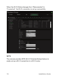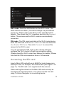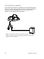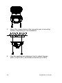
1
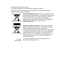
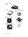
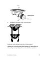
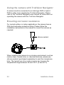
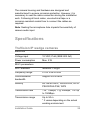
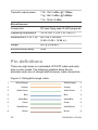
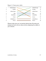
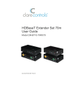
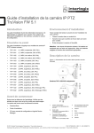
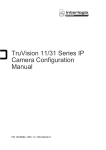
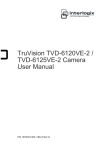
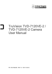
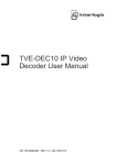
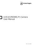
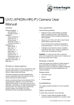
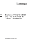
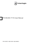
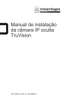
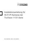
TruVision 11/31 Series Wi-Fi IP Camera Installation Guide P/N 1072907-EN • REV B • ISS 24APR15 Copyright © 2015 United Technologies Corporation, Interlogix is part of UTC Building & Industrial Systems, a unit of United Technologies Corporation. All rights reserved. Trademarks and patents Trade names used in this document may be trademarks or registered trademarks of the manufacturers or vendors of the respective products. Manufacturer Interogix 2955 Red Hill Avenue, Costa Mesa, CA 92626-5923, USA Authorized EU manufacturing representative: UTC Fire & Security B.V. Kelvinstraat 7, 6003 DH Weert, The Netherlands Certification N4131 This equipment has been tested and found to comply with the limits for a Class B digital device, pursuant to Part 15 of FCC Rules. These limits are designed to provide reasonable protection against harmful interference in a residential installation. This equipment generates, uses, and can radiate radio frequency energy and, if not installed and used in accordance with the instructions, may cause harmful interference to radio communications. However, there is no guarantee that interference will not occur in a particular installation. If this equipment does cause harmful interference to radio or television reception, which can be determined by turning the equipment off and on, the user is encouraged to try to correct the interference by one or more of the following measures: 1. Reorient or relocate the receiving antenna. 2. Increase the separation between the equipment and receiver. 3. Connect the equipment into an outlet on a circuit different from that to which the receiver is connected. 4. Consult the dealer or an experienced radio technician for help. CC Caution To assure continued compliance, use only shielded interface cables when connecting to computer or peripheral devices. Any changes or modifications not expressly approved by the party responsible for compliance could void the user’s authority to operate the equipment. This device complies with Part 15 of the FCC Rules. Operation is subject to the following two conditions: (1) This device may not cause harmful interference (2) This Device must accept any interference received, including interference that may cause undesired operation. Any changes or modifications not expressly approved by the party responsible for compliance could void the user’s authority to operate the equipment. Federal Communication Commission (FCC) Radiation Exposure Statement This equipment complies with FCC radiation exposure set forth for an uncontrolled environment. In order to avoid the possibility of exceeding the FCC radio frequency exposure limits, human proximity to the antenna shall not be less than 20 cm (8 inches) during normal operation. R&TTE Compliance Statement This equipment complies with all the requirements of DIRECTIVE 1999/5/CE OF THE EUROPEAN PARLIAMENT AND THE COUNCIL OF 9 March 1999 on radio equipment and telecommunication terminal Equipment and the mutual recognition of their conformity (R&TTE). The R&TTE Directive repeals and replaces in the directive 98/13/EEC (Telecommunications Terminal Equipment and Satellite Earth Station Equipment) as of April 8, 2000. Safety This equipment is designed with the utmost care for the safety of those who install and use it. However, special attention must be paid to the dangers of electric shock and static electricity when working with electrical equipment. All guidelines of this and of the computer manufacture must therefore be allowed at all times to ensure the safe use of the equipment. National Restrictions This device is intended for home and office use in all EU countries (and other countries following the EU directive 1999/5/EC) without any limitation except for the countries mentioned below: Country Restriction Reasons/remarks Bulgaria None General authorization required for outdoor use and public service France Outdoor use; limited to 10 mW e.i.r.p. within the band 24542483.5 MHz. Military Radiolocation use. Refarming of the 2.4 GHz band has been ongoing in recent years to allow current relaxed regulation. Full implementation planned 2012 Luxembourg None General authorization required for network and service supply(not for spectrum). Annex 3 B and A Wideband Data Transmission systems 2400.0-2483.5 MHz: Country Restriction Reasons/remarks Norway Implemented This subsection does not apply for the geographical area within a radius of 20 km from the centre of Ny-Ålesund. Italy Implemented The public use is subject to general authorization by the respective service provider. Russian Federation Limited implementation 1. SRD with FHSS modulation 1.1. Maximum 2.5 mW e.i.r.p. 1.2. Maximum 100 mW e.i.r.p. Permitted for use SRD for outdoor applications without restriction on installation height only for purposes of gathering telemetry information for automated monitoring and resources accounting systems. Permitted to use SRD for other purposes for outdoor applications only when the installation height is not exceeding 10 m above the ground surface. 1.3 maximum 100 mW e.i.r.p. indoor applications. 2. SRD with DSSS and other than FHSS wideband modulation 2.1. Maximum mean e.i.r.p. density is 2 mW/MHz. Maximum 100 mW e.i.r.p. 2.2. Maximum mean e.i.r.p. density is 20 mW/MHz. Maximum 100 mW e.i.r.p. It is permitted to use SRD for outdoor applications only for purposes of gathering telemetry information for automated monitoring and resources accounting systems or security systems. 2.3. Maximum mean e.i.r.p. density is 10 mW/MHz. Maximum 100 mW e.i.r.p. indoor applications. Ukraine Limited implementation e.i.r.p. ≤100 mW with built-in antenna with amplification factor up to 6 dBi. The following information shall also be included in the case of radio equipment intentionally emitting radio waves: (a) frequency band(s) in which the radio equipment operates; (b) maximum radio-frequency power transmitted in the frequency band(s) in which the radio equipment operates. 2012/19/EU (WEEE directive): Products marked with this symbol cannot be disposed of as unsorted municipal waste in the European Union. For proper recycling, return this product to your local supplier upon the purchase of equivalent new equipment, or dispose of it at designated collection points. For more information see: www.recyclethis.info. 2006/66/EC (battery directive): This product contains a battery that cannot be disposed of as unsorted municipal waste in the European Union. See the product documentation for specific battery information. The battery is marked with this symbol, which may include lettering to indicate cadmium (Cd), lead (Pb), or mercury (Hg). For proper recycling, return the battery to your supplier or to a designated collection point. For more information see: www.recyclethis.info. Contact information For contact information, see www.interlogix.com or www.utcfssecurityproducts.eu. Content Introduction 7 Product overview 7 Installation 7 Installation environment 7 Package contents 8 Cable requirements 11 Camera description 11 Setting up the camera 12 Setting up Wi-Fi transmission 12 Accessing the SD card 19 Connecting a speaker 20 Mounting the wedge camera 21 Using the camera with a recorder 23 Using the camera with TruVision Navigator 24 Ensuring corrosion resistance 24 Specifications 25 TruVision IP wedge cameras 25 Pin definitions 26 6 Installation Guide Introduction Product overview This is the installation guide for TruVision 11-31 Series Wi-Fi IP camera models: TVW-1103 (1.3MPX Wi-Fi, 2.8mm lens, Grey, PAL) TVW-3103 (1.3MPX Wi-Fi, 2.8mm lens, Grey, NTSC) TVW-1104 (1.3MPX Wi-Fi, 2.8mm lens, White, PAL) TVW-3104 (1.3MPX Wi-Fi, 2.8mm lens, White, NTSC) TVW-1105 (3MPX Wi-Fi, 2.8mm lens, Grey, PAL) TVW-3105 (3MPX Wi-Fi, 2.8mm lens, Grey, NTSC) TVW-1106 (3MPX Wi-Fi, 2.8mm lens, White, PAL) TVW-3106 (3MPX Wi-Fi, 2.8mm lens, White, NTSC) TVW-1116 (3MPX Wi-Fi, 6mm lens, White, PAL) TVW-3116 (3MPX Wi-Fi, 6mm lens, White, NTSC) Installation This section provides information on how to install the cameras. Installation environment When installing your product, consider these factors: • Electrical: Install electrical wiring carefully. It should be done by qualified service personnel. Always use a proper PoE switch or a 12 VDC UL listed Class 2 or CE certified Installation Guide 7 power supply to power the camera. Do not overload the power cord or adapter. • Ventilation: Ensure that the location planned for the installation of the camera is well ventilated. • Temperature: Do not operate the camera beyond the specified temperature, humidity or power source ratings. The operating temperature of the camera is between -30 to +60°C (-22 to 140°F). Humidity is below 90%. • Moisture: Do not expose the camera to rain or moisture, or try to operate it in wet areas. Turn the power off immediately if the camera is wet and ask a qualified service person for servicing. Moisture can damage the camera and also create the danger of electric shock. • Servicing: Do not attempt to service this camera yourself. Any attempt to dismantle or remove the covers from this product will invalidate the warranty and may also result in serious injury. Refer all servicing to qualified service personnel. • Cleaning: Do not touch the sensor modules with fingers. If cleaning is necessary, use a clean cloth with some ethanol and wipe the camera gently. If the camera will not be used for an extended period of time, put on the lens cap to protect the sensors from dirt. Package contents Check the package and contents for visible damage. If any components are damaged or missing, do not attempt to use the unit; contact the supplier immediately. If the unit is returned, it must be shipped back in its original packaging. 8 Installation Guide IP wedge camera Camera Installation manual CD with Configuration Manual and TruVision Device Finder Template A for mounting with the converter pan Screws Template B for mounting without the converter pan Drywall anchor Φ7.5 x 24.5mm (3 pcs) Screw M4 (4 x 25mm (3 pcs) Installation Guide 9 Water joint: provide water resistance to network connection. 12 VDC connector: DC jack socket to terminal connectors with positive and negative indicators. Screws C: M4×8, 2pcs Tamper-resistant hex wrench Lens alignment tool Converter pan WEEE and battery disposal CAUTION: Use direct plug-in UL listed power supplies marked Class 2/CE certified or LPS (limited power source) of the required output rating as listed on the unit. CAUTION: Risk of explosion if battery is replaced by an incorrect type. Dispose of used batteries according to the instructions. 10 Installation Guide Cable requirements For proper operation, adhere to the following cable and power requirements for the cameras. Category 5 cabling or better is recommended. All network cabling must be installed according to applicable codes and regulations. Camera description Figure 1: IP wedge camera 1 2 10 6 9 11 8 3 5 4 1. 2. 3. 4. 5. 6. 7 Camera cover/housing Lens SD card Ethernet RJ45 PoE port Power supply Base Installation Guide 7. Alarm and Audio port 8. Reset/WPS button 9. Converter pan 10. Antenna 11. Microphone 11 Setting up the camera Note: If the light source where the camera is installed experiences rapid, wide variations in lighting, the camera may not operate as intended. To quickly put the camera into operation: 1. Prepare the mounting surface. 2 Mount the camera using the appropriate fasteners. See “Mounting the wedge camera” on page 21. 3. Set up the camera’s network and streaming parameters so that the camera can be controlled over the network. For further information, please refer to the “TruVision IP Camera Configuration Manual”. 4. Program the camera to suit its location. For further information, please refer to the “TruVision 11/31 Series IP Camera Configuration Manual”. Setting up Wi-Fi transmission For setting up the Wi-Fi transmission, please refer to the “TruVision 11/31 Series IP Camera Configuration Manual” for details. Wi-Fi transmission distance The Wi-Fi transmission distance/range of the camera is approximately 50 m (164 ft.) in open air applications. Note: The transmission distance may vary due to the presence of physical obstacles, such as trees, walls, elevators, fire doors, furniture, etc. Avoid very solid walls and metallic objects in the transmission path. Other Wi-Fi networks (for example Wi-Fi, WiMAX) operating on 2.4 GHz and certain types of devices (e.g., microwave oven point-to-point Wi-Fi transmission) can 12 Installation Guide cause interference with your network. The result would lead to a reduction in transmission distance/range. Access the camera via a Wi-Fi network (Ad-Hoc mode) Note: The camera is in Ad-Hoc mode by default. The SSID is the serial number. 1. Power up the camera. 2. From your computer, search for the SSID that was set up for the camera for Ad-Hoc mode. Select the SSID to connect the camera. Installation Guide 13 3. When connected, open TruVision Device Finder or Device Manager and change the IP address of the camera to that of the same subnet of the router. Note: The computer Wi-Fi IP address should also be in the same subnet. 14 Installation Guide 4. Log on the camera via web browser and browse to the WiFi page. 5. Select the desired Wi-Fi and enter the key, if required. Installation Guide 15 6. Click Save to save the settings. 7. When the camera is connected to the router, the ad-hoc is disconnected. On the laptop, select the Wi-Fi router and connect it. 8. Open the device finder to check the WLAN IP address of the camera. Log in to the camera to see live view. 16 Installation Guide Access the camera via a network cable When configuring the Wi-Fi settings for the first time, connect the camera to the router via a network cable and then open the web browser to complete the Wi-Fi setup by clicking Save. Installation Guide 17 When the Wi-Fi Status changes from “Disconnected” to “Connected”, the Wi-Fi connection is set up successfully. WPS The camera provides WPS (Wi-Fi Protected Setup) feature to easily set up a Wi-Fi connection to a Wi-Fi router. 18 Installation Guide PBC mode: Push the WPS button on the Wi-Fi router. The WPS indicator will flash. (The WPS settings may be different per device. Please refer to the Wi-Fi router User Manual for details). Then check the PBC checkbox and click the Connect button. The camera and the Wi-Fi router are automatically connected. PIN mode: The PIN code is printed on the Wi-Fi router device. Enter the PIN code in the Router PIN Code bar and check the Use Router PIN Code. Then click Connect to connect the camera to the Wi-Fi router. You can generate the PIN code on the camera side and configure the Wi-Fi router to finish the connection setting. (Please check the Wi-Fi router User Manual for details). Please note that the PIN code expiration time is 120 seconds. Accessing the SD card Insert a Micro SD card with up to 64GB for local storage as a backup in case, for example, the network fails (see Figure 1 on page 11). The SD card is not supplied with the camera. Video and log files stored on the Micro SD card can only be accessed via the web browser. You cannot access the card using TruVision Navigator or a recording device. Installation Guide 19 Connecting a speaker The camera has a built-in microphone to the collect audio input signal. For audio output, please connect an external speaker to the Audio Output and GND interface of the camera. The speaker is not supplied with the camera. GND Audio Output Note: The speaker need be powered correctly with a power supply. Please check the speaker specification and user manual for more details. 20 Installation Guide Mounting the wedge camera To mount the wedge camera on a wall or ceiling: 1. Drill the holes for the mounting hardware in the mounting surface using the supplied drill template. To route the cables from the base of the camera, drill a cable access hole in the mounting surface. 2. Mount the converter pan to the mounting surface (optional). Note: If required, you can remove the tab (A) on the side of the converter pan to pass the cables through. A 3. Loosen the screws with the tamper-resistant hex wrench (supplied) to remove the camera cover. Installation Guide 21 4. Mount the camera base to the converter pan or mounting surface, depending on the installation. 5. Use the supplied lens alignment tool to adjust the pan [±30°], tilt [0 to 80°], and rotation direction [0 to 360°]. 22 Installation Guide Pan Adjusting tool Rotation Tilt 6. Re-attach the dome cover to the camera. Using the camera with a recorder Please refer to the recorder user manuals for instructions on connecting and operating the camera with these systems. Installation Guide 23 Using the camera with TruVision Navigator A camera must be connected to an Interlogix NVR or hybrid DVR in order to be operated by TruVision Navigator. Please refer to the TruVision Navigator user manual for instructions on operating the camera with the TruVision Navigator. Ensuring corrosion resistance For normal outdoor or indoor applications, the camera has an IP66 dust and water protection rating. Please follow the installation instructions in the manual to mount the camera as required. silicone sealant When installing the camera in a corrosive environment, such as marine ships, coastal sites, or chemical factories, please use silicone sealant (purchased separately) to seal the microphone hole. The typical cure time is about one to two hours in the temperature range between 40 and 100°F (5 and 40°C). 24 Installation Guide The camera housing and hardware are designed and manufactured to ensure corrosion protection. However, it is necessary to seal the cable connection during the installation work. Following all local codes, use electrical tape or a corrosion-resistant conduit box to connect the cables as required. Note: Sealing the microphone hole impacts the sensitivity of camera audio input. Specifications TruVision IP wedge cameras Electrical Voltage input 12 VDC, PoE (IEEE 802.3af) Power consumption Max. 5 W Wi-Fi parameters Wi-Fi standard IEEE802.11b/g/n Frequency range 2.4 to 2.4835 GHz Communication bandwidth Support 20/40 MHz Security 64/128-bit WEP, WPA/WPA2, WPAPSK/WPA2-PSK, WPS Transmission rate 11b: 11Mbps, 11g: 54Mbps, 11n: up to 150Mbps Transmission range Up to 50 m * It varies depending on the actual working environment. Installation Guide 25 Transmit output power 11b: 17±1.5 dBm @ 11Mbps 11g: 14±1.5 dBm @ 54Mbps 11n: 12.5±1.5 dBm Miscellaneous Connectors DC jack flying lead, RJ45 flying lead Operating temperature -30 to +60°C (-22°F to +140°F) Dimensions (L × W × H) 98 × 89 × 329 mm (3.86 ×3.49 × 12.94 in.) Weight 407 g (0.89 lbs.) Environmental rating IP66 Pin definitions There are eight wires on a standard UTP/STP cable and each wire is color-coded. The following graphics show the pin allocation and color of straight and crossover cable connection: Figure 2: Straight-through cable 1 White/Orange 2 Orange 3 White-Green 4 Blue 5 White/Blue 6 Green 7 White/Brown 8 Brown 26 White/Orange 1 Orange 2 White-Green 3 Blue 4 White/Blue 5 Green 6 White/Brown 7 Brown 8 Installation Guide Figure 3: Cross-over cable 1 White/Orange 2 Orange 3 White-Green 4 Blue 5 White/Blue 6 Green 7 White/Brown 8 Brown White/Orange 1 Orange 2 White-Green 3 Blue 4 White/Blue 5 Green 6 White/Brown 7 Brown 8 Please make sure your connected cables have the same pin assignment and color as above before deploying the cables in your network. Installation Guide 27 28 Installation Guide