1
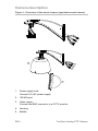
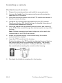
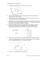
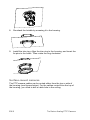
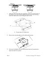
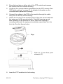
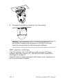
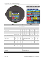
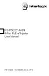
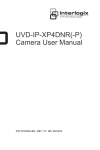
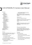
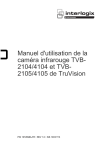
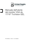
TruVision Analog PTZ Camera Installation Manual P/N 1072692A-EN • REV 1.0 • ISS 10OCT13 Copyright © 2013 UTC Fire & Security Americas Corporation, Inc. Interlogix is part of UTC Climate Controls & Security, a unit of United Technologies Corporation. All rights reserved. Trademarks and patents Manufacturer TruVision name and logo are trademarks of United Technologies. Other trade names used in this document may be trademarks or registered trademarks of the manufacturers or vendors of the respective products. UTC Fire & Security Americas Corporation, Inc. 2955 Red Hill Avenue, Costa Mesa, CA 92626-5923, USA Authorized EU manufacturing representative: UTC Fire & Security B.V. Kelvinstraat 7, 6003 DH Weert, The Netherlands Certification FCC compliance N4131 Class B: This equipment has been tested and found to comply with the limits for a Class B digital device, pursuant to part 15 of the FCC Rules. These limits are designed to provide reasonable protection against harmful interference in a residential installation. This equipment generates, uses, and can radiate radio frequency energy and, if not installed and used in accordance with the instructions, may cause harmful interference to radio communications. There is no guarantee that interference will not occur in a particular installation. If this equipment does cause harmful interference to radio or television reception, which can be determined by turning the equipment off and on, the user is encouraged to try to correct the interference by one or more of the following measures: • European Union directives Reorient or relocate the receiving antenna. • Increase the separation between the equipment and receiver. • Connect the equipment into an outlet on a circuit different from that to which the receiver is connected. • Consult the dealer or an experienced radio/TV technician for help. 12004/108/EC (EMC directive): Hereby, UTC Fire & Security declares that this device is in compliance with the essential requirements and other relevant provisions of Directive 2004/108/EC. 2002/96/EC (WEEE directive): Products marked with this symbol cannot be disposed of as unsorted municipal waste in the European Union. For proper recycling, return this product to your local supplier upon the purchase of equivalent new equipment, or dispose of it at designated collection points. For more information see: www.recyclethis.info. Contact information For contact information, see www.interlogix.com or www.utcfssecurityproducts.eu. Content Introduction 3 Product overview 3 Before you begin 4 Installation environment 4 Camera description 5 Installing a camera 6 Pendant-mount cameras 6 Flush-mount cameras 7 Surface-mount cameras 8 DIP switch settings 11 Specifications 14 Introduction This pocket guide provides basic information on setting up and using the TruVision Analog PTZ Camera. Detailed information on the cameras can be found in the configuration manual. Product overview This is the user manual for TruVision analog PTZ camera models TVP-2101 (23X pendant, PAL) TVP-4101 (23X pendant, NTSC) TVP-2102 (23X surface, PAL) TVP-4102 (23X surface, NTSC) TVP-2103 (23X flush, PAL) TVP-4103 (23X flush, NTSC) TVP-2104 (36X pendant, PAL) TVP-4104 (36X pendant, NTSC) TVP-2105 (36X surface, PAL) TVP-4105 (36X surface, NTSC) TruVision Analog PTZ Camera 3 EN TVP-2106 (36X flush, PAL) TVP-4106 (36X flush, NTSC) Before you begin Unpack everything. Check the items for damage, and verify that all items are included. The camera is shipped with the following items: Dome camera Installation manual CD with configuration manual Installation environment When installing your camera, consider these factors: • Place the camera in a secure location. • Ensure that the camera is in a well-ventilated area. • Do not expose the camera to rain or moisture. EN 4 TruVision Analog PTZ Camera Camera description Figure 1: Overview of the dome camera (pendant-mount shown) 5 1 2 3 4 1. Power supply cord. Connect 24 VAC power supply 2. RS-485 port 3. Video output. Connect the BNC connector to a CCTV monitor. 4. Housing. 5. Bubble. EN 5 TruVision Analog PTZ Camera Installing a camera Pendant-mount cameras 1. Prepare the mounting surface and install the camera bracket. 2. Unscrew the bubble from the camera and remove the protective tape from the PTZ module. 3. Press the two tabs on either side of the PTZ module and remove it from the camera housing. 4. Configure the communication parameters for the PTZ camera. Please see Section DIP Switch Settings for detailed information of communication parameters settings. 5. Route the cables from the pendant-mount bracket, and connect it to the PCB of the module through the cable entry hole on top of the housing. Note: If alarm and audio input/output relays are to be used, also connect them to the PCB of the module. 6. Attach the camera housing to the bracket using the screws enclosed with the bracket. 7. Insert the PTZ module into the housing: Position the tabs on the PTZ module by aligning the arrow label on the module with those on the housing (see below). The module should snap firmly into position. If using an SD card, insert it into the module before inserting the module into the housing. 8. Re-attach the bubble by screwing it to the housing. EN 6 TruVision Analog PTZ Camera Flush-mount cameras 1. Using the drill template, drill a hole on the ceiling. 2. Unscrew the bubble from the camera and remove the protective tape from the PTZ module. 3. Press the two tabs on either side of the PTZ module and remove the module from the camera housing. 4. Configure the communication parameters for the PTZ camera. See the section “DIP switch settings” on page 11 for detailed information on the communication parameters settings. 5. Adjust the height of the two housing tabs by turning the screw on which they are attached. The distance (h) of the tabs from the housing ring must be greater than the thickness of the ceiling. Housing tab Screw 6. Make sure the housing tab is closed and then PUSH the housing into the pass-through hole. Hold the housing and fix it by screwing the housing tabs down to the mounting surface. 7. Insert the PTZ module into the housing: EN 7 TruVision Analog PTZ Camera 8. Re-attach the bubble by screwing it to the housing. 9. Install the trim ring. Align the trim ring to the housing, and insert the fix-pins to the holes. Then rotate the ring clockwise. Surface-mount cameras The PTZ camera cables can be routed either from the top or side of the housing (see figures below). For the cables routed from the top of the housing, you need to drill a cable hole in the ceiling. EN 8 TruVision Analog PTZ Camera 1. Using the mounting base as a template, mark four screw holes on the ceiling. If you are routing cables from the top of the housing, mark the cable hole on the ceiling and drill a hole. B A A. Screw holes; B. Cable hole 2. Secure the mounting base to the ceiling with screws. 3. Unscrew the bubble from the camera and remove the protective tape from the PTZ module. EN 9 TruVision Analog PTZ Camera 4. Press the two tabs on either side of the PTZ module and remove the module from the camera housing. 5. Configure the communication parameters for the PTZ camera. See “DIP switch settings” on page 11 for detailed information on the communication parameters settings. 6. Connect the cables to the PCB of the module through the cable entry hole on the top of the housing. 7. Attach the housing to the mounting base. Align the arrow head with the spring end of the mounting base. Push the housing up and then sideways in the direction of arrow. When the housing is correctly positioned, the spring automatically snaps firmly into the lock clip. See the figures below. Align Push up (1) and then push sideways (2). Lock clip 8. Insert the PTZ module into the housing: EN 10 TruVision Analog PTZ Camera 9. Re-attach the bubble by screwing it into the housing. Warning: After installation, the PTZ module will perform a PTZ self-test and initializes with the power on. DO NOT touch and move the camera while it is self-testing and initializing. DIP switch settings Two DIP switches, SW1 and SW2, are used to set the PTZ dome address, baud rate, protocol, etc. The values are ON=1 and OFF=0. See Figure 2 on page 12. Each DIP switch number represents a DIP switch value, ranging from 1 to 8 from the lowest to highest. EN 11 TruVision Analog PTZ Camera Figure 2: DIP switch settings SW 1 SW 2 SW1 - ADDRESS Rx Address = Switch Value Switch1 Number 1 2 3 4 5 6 7 8 Switch1 Value 1 2 4 8 16 32 64 128 Rx Broadcast Address 0 off off off off off off off off Rx Address 1 on off off off off off off off Rx Address 255 on on on on on on on on SW2 – Baud Rate Settings SW2 – Protocol Settings Switch2 Number 1 2 3 Switch2 Number 4 5 6 2400 Baud on off off Interlogix/GE Impac RS- off off off 485 4800 Baud off on off PELCO-D on off off 9600 Baud on on off PELCO-P off on off 19200 Baud off off on Reserved Others 38400 Baud on off on The rest of above is 9600 Baud Termination Settings Switch Number 7 Switch Number 8 Reserved Not Terminated off Terminated EN 12 on TruVision Analog PTZ Camera Address settings DIP switch SW1 is used to set the address of the PTZ dome. See Table 1 below to set the PTZ camera address to a specific number. Table 1: PTZ camera addresses Address 1 2 3 4 5 6 7 8 0 OFF OFF OFF OFF OFF OFF OFF OFF 1 ON OFF OFF OFF OFF OFF OFF OFF 255 ON ON ON ON ON ON ON ON Baud rate settings Use positions 1, 2, and 3 of DIP switch SW2 to set the baud rate of the PTZ dome. The values to select are 2400 bps, 4800 bps, 9600 bps, 19200 bps and 38400 bps. The default baud rate is 2400 bps. See Table 2 below. Table 2: Baud rate values Baud rate 1 2 3 2400 ON OFF OFF 4800 OFF ON OFF 9600 ON ON OFF 19200 OFF OFF ON 38400 ON OFF ON Protocol Settings Use positions 4, 5, and 6 of DIP switch SW2 to set the communication protocols of the dome. See Table 3 below. Table 3: Protocol values Protocol 4 5 6 Interlogix-485 OFF OFF OFF PELCO-D ON OFF OFF PELCO OFF ON OFF Reserved Others EN 13 TruVision Analog PTZ Camera Specifications Operating temperature Pendant-mount housing: -30 to +65 °C Flush-mount housing: -20 to +65 °C Surface-mount housing: -20 to +65 °C Power supply 24 VAC +/- 3.6 VAC Power consumption Pendant-mount housing: Max. 35 W Flush-mount housing: Max. 15 W Surface-mount housing: Max. 15 W Dimensions (mm) Pendant-mount housing: Ø 220 × 266 mm Flush-mount housing: Ø 206 × 251 mm Surface-mount housing: Ø 180 × 240 mm Environmental Pendant-mount housing: IP66 Flush-mount housing: IP54 Surface-mount housing: IP44 Weight Pendant-mount housing: 3.5 kg Flush-mount housing: 3 kg Surface-mount housing: 2.5 kg EN 14 TruVision Analog PTZ Camera