1
Aicure UV Curing System
LED Spot Type
UJ20 Series
User’s Manual
Thank you for your purchase of the Aicure LED spot UV curing system.
In order to use the system correctly, please read this User's Manual carefully before use.
After you have read it, store it in a secure location, and refer back to it if you have any
uncertainties.
LED product safety precautions
LED Product Classification
The light source of the LED head connected to this product is classified as 3B
under the JIS C6802 “Safety of laser products.”
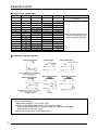
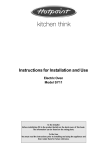
Max output: 330mW
Class 3B LED Product
Wavelength: 365±5nm
JIS C6802 : 2005
DANGER
Controlling or calibrating this product by other than the procedures stipulated here
could cause exposure to dangerous LED radiation.
- Do not look directly at LED-UV light, or at LED-UV light reflected in a mirror or
other reflective surface. Doing so could cause eye damage.
- Install the main unit so that humans are not exposed to LED-UV light.
Exposure could injure the skin or cause other injury.
- Always turn off the key switch, before cleaning the LED head.
Cleaning the head while the switch is on could cause eye damage or injury to the
skin.
- Never disassemble this product. Disassembling this product could cause
exposure to LED-UV light, causing eye damage or injury to the skin.
- If there is a risk of the LED-UV light being exposed to UV reflective light, place
the product inside a cover with proper reflectance and heat characteristics to
block that reflective light.
- When operating the controller, set up the system so that the path of the LED-UV
light is not at eye level.
- It is strongly recommended that a protective barrier be placed around the product
so that people cannot approach it while it is operating.
- Always wear the UV protective goggles when using this product.
- Never operate this product in a manner not described in this manual. Doing so
risks exposure to LED-UV light.
Safety Precautions for Users
JIS C6802 stipulates user guidelines pertaining to safety precautions to be taken by
users and management standards. In the case of this product, please implement
safety precautions for a class 3B LED product. See JIS C6802, “Safety of laser
products” for details. In the abroad, see the standard according each country.
ii
Safety features for LED products
Safety features
This product is equipped with the following safety features based on JIS C6802 Safety of laser
products.
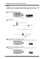
Remote interlock
UV radiation can be stopped by opening INPUT terminal “EMER (11)” on the rear of the
controller. It is shorted with a shorting bar as a factory default.
Control by a key switch
The controller unit of this product is started via a key switch. Ensure that the key is removed
while this product is not in use.
LED radiation warning
Turning ON the key switch enables the irradiation of LED UV light, which turns on the
irradiation warning indicator on the front panel of the controller. If the LED connection cable is
longer than 2 m, or if the controller unit is installed in an invisible part of the equipment,
another warning indicator needs to be provided in a visible location around the LED head.
[OUTPUT terminals “+5V” (23) and “GND” (24) on the rear of the controller output signals
when the key switch is turned ON.]
Stays on during irradiation.
The emitting channel number flashes.
Emergency reset
If an error occurs, eliminate the cause and then hold down “SET” for one or two seconds to
clear the error. Or, hold down “SET” for five seconds or more to forcibly clear the error.
iii
Safety features for LED products
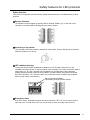
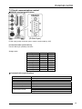
Labels
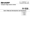
The LED irradiation warning labels shown below specified by JIS C6802 are attached to the LED
heads before this product is shipped from the factory. Warning labels in Chinese that comply with
GB standards and those in English that comply with IEC/EN standards are also included.
Warning labels in Japanese (JIS)
Description
Warning mark
Emission hole location
indication label
Label locations
Description and mark label
Emission hole location indication label
Emission hole
LED head
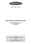
Warning labels in Chinese (GB standards)
If this product is used in China, attach the labels shown below over the Japanese labels.
Warning labels in English (IEC/EN standards)
If this product is used outside Japan or China, attach the labels shown below over the
Japanese labels.
iv
Safety precautions
The purpose of the following caution indications is to ensure the safe and correct use of this
product in order to protect users from injury and prevent property damage.
The caution indications to prevent possible human injury and property damage caused by
incorrect use are classified into “DANGER” and “WARNING” depending on their
degree and severity.
All caution indications are critical for ensuring safety and must be strictly
observed.
DANGER
WARNING
Failure to observe the instructions can result in death or serious injury.
Failure to observe the instructions can result in injury or property damage.
Symbol examples
:
z:
This symbol denotes a Prohibited action.
The left-hand example denotes “Do not disassemble”.
This symbol denotes a Mandatory action or an Instruction.
The left-hand example denotes “Mandatory”.
DANGER
While the LED is lit, protect your eyes and skin from direct exposure to the
light and any strong reflections.
Prohibited
Failure to do so may result in inflammation of the eyes or skin.
This product uses a Class 3B LED source.
Wear protective the UV goggles and other protective gear during operation.
Mandatory
Failure to do so may result in inflammation of the eyes or skin.
The wavelengths of some UV rays generated by this product are 365 nm. Therefore, make sure
to wear UV-filtering goggles
Never disassemble, repair, or modify this product in any way other than
specified in this User Manual.
Do not
disassemble
Such actions may result in an accident or injury.
WARNING
Make sure to disconnect the power plug from the outlet after use of this
product.
Insulation deterioration may result in electrical shock or fire.
Pull the plug, not the cord, to unplug this product.
Mandatory
A short circuit may result in electrical shock or fire.
Do not use any input power supply outside the specified range.
Such actions may result in fire.
If the power cord or plug is damaged, or if contact between the plug and
receptacle is loose, do not use the product.
Such actions may result in electrical shock, short circuit, or fire.
Do not use this product in a place where temperatures vary widely or dew
condensation occurs.
Such actions may result in product malfunction.
Prohibited
Do not use this product in a place where a large vibration or impact can be
applied.
Such actions may result in product malfunction.
Do not hold the controller by hand during use. (This is not a hand-held type.)
Such actions may result in electrical shock.
v
Precautions for use
1)
2)
3)
4)
5)
6)
7)
8)
9)
10)
11)
12)
13)
Do not connect this product to any power supply outside the power supply voltage and frequency
range indicated on the main unit and in this User’s Manual. Otherwise, this product may be
damaged. The power cable supplied with this product is a 100 V cable for use in Japan only.
When using this product outside Japan, use a power cable that has been certified by applicable
standards and has a plug shape that fits the receptacle used in each country.
Use this product under the following operating conditions; otherwise, the product life may be
shortened.
Ambient temperature: Controller: 0 to 35°C
Head: 5 to 35°C
Relative humidity:
85% or lower (with no condensation)
Operation environment: Use this product in a location with minimum dirt, dust, or oil mist under
no extreme temperature changes, severe vibrations, or shock.
Storage temperature: -10 to +60°C at 85% or lower relative humidity (with no condensation)
Do not place anything on the controller or block the air vents around this product to prevent the
occurrence of burns due to overheating.
When using more than one controller, do not bundle the supplied AC adapters together. The AC
adapters may overheat and damage the products.
When handling the LED head, do not touch the lens or LED with bare hands.
If a foreign substance adheres to the lens or LED, it can cause the UV intensity to decrease and
the curing performance to degrade. If bare hands touch the lens or LED, wipe it clean with
alcohol.
Be careful not to drop or apply shock to the LED head. Doing so may damage this product.
Do not repeatedly bend the LED head or the connection cable, as this may result in breakage.
If any part of the LED head is broken, the whole LED head must be replaced.
Set the rubber feet of this product on a flat horizontal surface.
Do not tilt this product or put it on its side or upside down during use. The product may overheat
and be damaged.
Noise superimposed on the power supply may cause the LED head or control power supply to
malfunction. In such cases, install an insulating transformer or a noise filter.
Do not share a power supply with an motor, dielectric machinery, or equipment that consumes
high power.
Do not use any cable other than the supplied connection cable to connect the LED head to the
controller.
Ensure that the connection cable approx. 80 mm from the connector is kept free from flexing
stress and the joint between the connector and the cable is kept free from tension. Otherwise, the
cable may be broken.
If the LED connection cable is longer than 2 m, or if the controller unit is installed in an invisible
part of the equipment, a warning indicator needs to be provided in a visible location around the
LED head. Use “+5V” (23) and “GND” (24) on the rear of the controller as outputs for the indicator.
They output signals when the key switch is turned ON.
Warranty
- This product will be repaired free of charge if it malfunctions under normal use conditions within one
year of delivery.
Note that, however, the warranty does not apply to malfunctions attributable to your company,
consumables, and/or unavoidable problems resulting from such occurrences as natural disasters.
- The warranty for the LED head is valid for one year from delivery or 5,000 hours of total irradiations,
whichever comes first.
Compensation for Production
- We will not compensate the user for losses due to production shutdowns and/or defects caused by
any malfunction of this product.
vi
Contents
1 Features of the ANUJ5024 Aicure ........................ 1
2 Product components ............................................. 3
7 External control....................................................37
7.1
External input/output control ..........................37
7.2
Serial communication control.........................39
RS232C terminal specifications ....................39
3 Part names and functions ..................................... 4
Communication specifications.......................39
Switch panel ..................................................... 5
Commands and responses ...........................40
Simple mode setting ......................................... 6
Control commands ........................................40
Operation flowchart......................................... 10
Error codes ....................................................41
Command/response format...........................41
4 Installation........................................................... 11
4.1
4.2
Utility software (for control from a PC) ..........42
Installation conditions .................................... 11
General guide for irradiation distance and
8 Warning displays .................................................43
UV intensity.................................................... 12
Temperature warning.......................................43
Time warning ...................................................43
5 Getting started .................................................... 14
Error codes ......................................................44
5.1
Hooking up the connection cable................... 14
5.2
Connecting the LED....................................... 14
9 Safety measures..................................................45
5.3
Connecting the external control signals......... 16
9.1
5.4
Connection of the AC adapter........................ 17
5.5
Power-on operation ....................................... 17
Safety circuit ..................................................45
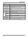
10 Specifications ....................................................46
Overall specification ........................................46
6 Operation modes ................................................ 18
6.1
Auto mode (Set by default when the power is
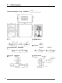
11 Dimensions........................................................48
turned on) .................................................... 19
6.2
Manual (MNL) mode...................................... 23
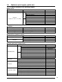
12 Options and spare parts list...............................49
6.3
Irradiation mode (ALL/MULTI) ....................... 26
12.1 Product numbers for placing orders...............49
6.4
Start signal mode (PULSE/STATUS)
12.2 How to replace the lens .................................50
(PULSE/STATUS) ........................................ 27
6.5
LED replacement time (x100hrs)
13 Troubleshooting.................................................51
6.6
setting mode.................................................. 27
2
UV intensity (W/cm ) measurement/
Manual revision history............................................52
calibration mode ............................................ 28
6.7
Product type (TYPE) switching mode............ 30
6.8
Program (PROG) setting mode ..................... 30
6.9
Power (PWR) mode ...................................... 32
6.10 Setting lock function ...................................... 32
6.11 Irradiation mode setting................................. 33
ALL irradiation mode (batch irradiation) ........ 33
MULTI irradiation mode
(individual irradiation) .................................... 35
vii
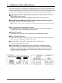
1 Features of the UJ20: Aicure
The UJ20: Aicure is an UV curing system that quickly hardens UV resins (inks, adhesives, and
coatings) via irradiation with UV light from an LED light source. Focused irradiation of UV resins
coated on minute surfaces (2 to 3 mm dia.) such as the lenses of CD, MD, and DVD players, and
the LCD panels of notebook PCs and the like, with UV radiation enables precise adhesion.
High-power irradiation: 8,000 mW/cm2 (When the Power Mode is on and an
ANUJ61523 head is used)
Higher intensity and wider range of irradiation reduces the production cycle time.
Long LED life: 20,000 hours (LED life: Total irradiation time before the UV
intensity becomes 70% of the initial value)
This LED life is over six times that of our conventional lamp model and reduces the running
cost.
■ UV curing without temperature increases
A single 365-nm LED UV light source is used, which does not include infrared radiation.
This eliminates the risk of heat damage to the workpiece.
■ Stable UV intensity
UV intensity is kept constant, even if the ambient or LED temperature changes.
■ Easy-to-install LED head
At 12 mm dia. x 50 mm len., the LED is easy to mount on a jig. Mounting the LED head in
place reduces overheating and increases UV intensity.
■ No cooling fan construction allows the use in a clean room
There is no need to deal with exhaust.
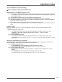
Programmable UV irradiation with four individually controlled heads
Each LED head can be independently controlled. The heads can also be controlled all
together or in combination. Up to 16 different operation programs can be stored for each
channel, including one program for the constant intensity irradiation and 15 programs
composed of up to 10 steps each.
Program examples
Up to 15 programs can be set.
Program 1
Constant
intensity
Time
[Lamp type] Four units need to be
[UJ20] One controller handles
installed separately for
processes 1 to 4.
processes 1 to 4.
Program 15
Interval (closed)
UV intensity
Simple mode
Fiber:
Process 1 Process 2 Process 3 Process 4
Process 1 Process 2 Process 3 Process 4
1
Features of the ANUJ5024 Aicure
Universal design for easy operation
Easy operation has been achieved by the product’s universal design, including the large-sized
color LED display with a high level of visibility and the operation switches located at optimal
locations.
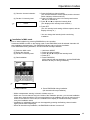
In simple mode, UV irradiation can be started simply by setting the UV power and irradiation
time, and then pressing [EMISSION].
(1) Press [SET], choose
TYPE 00 (simple mode),
and press [CH1] (the
target head).
(2) Set the irradiation
intensity by pressing [T]
and [S] switches, and
press [SET].
(3) Set the irradiation time
by pressing [T] and [S]
switches, hold down [SET],
and press [EMISSION] to
start UV irradiation.
Multiple safety features
This product has a function to detect breaks and short-circuiting of the LED head. The LED is
automatically turned off if it overheats due to ambient temperature rise or other conditions. UV
irradiation can be brought to an emergency stop by opening INPUT terminal “EMER (11)” and
short-circuiting “STOP (9)” and “COM (12)” on the rear of the controller during irradiation.
Detachable terminal blocks for external connection
The detachable terminal blocks facilitate connections with external equipment.
Universal power supply
The supplied AC adapter is a universal type for 100 to 240 V AC ± 10%.
(The supplied AC adapter power cable is a 100 V AC cable for use in Japan only.)
2
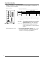
2 Product components
Please check the contents of your package.
Basic package
Controller
AC adapter (100-240VAC)
100 V AC power cable for use in Japan only
When using this outside Japan, use a power
cable that has been certificated by applicable
standards and has a plug shape that fits the
receptacle in each country.
User’s Manual
Optional components
Cable labels (attached to the connection cable)
Connection cable
LED head (with lens)
3
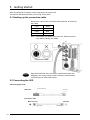
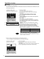
3 Part names and functions
Front of the controller
EMISSION switch
READY indicator
Status indicator
Operation setting indicator
Data display (7 segments)
CH selector/indicator
Key lock indicator
Setting switches
Key operated power switch
UV sensor connection port
UV sensor (Option)
Rear of the controller
LED connection cable connector
Input connector (Pin Nos. 1 to 12)
Output connector (Pin Nos. 13 to 24)
Interlock line (Pin Nos. 11 and 12)
Communication connector (RS232C, 9 pins)
Connector for the supplied AC adapter (6 V DC)
Supplied AC adapter
DC output indicator LED
100 VAC power cable for use in Japan only.
4
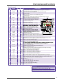
Part names and functions
Switch panel
No.
Name
1
EMISSION
○
Description
2
MODE
○
3
SET
○
4
CH1 - 4
○
Red
Green
Starts/stops MNL irradiation, and starts/emergency-stops AUTO irradiation.
The indicator stays on during irradiation.
When held down, switches between the setting and AUTO modes.
Cancels the entry.
When held down, switches to the TYPE00 setting mode.
Accepts the entry.
When held down in setting mode, saves the accepted settings in memory.
Switches the display and selects the channel.
Flashes in the AUTO mode or setting mode.
Lit when the program selection is accepted.
5
▼
○
Decreases the setting value.
6
7
8
▲
UV PWR
TIME
○
○
○
Increases the setting value.
Switches to the UV intensity level display.
Switches to the UV irradiation time display.
9
10
READY
CH1 - 4
Green Stays on while AUTO irradiation is ready.
*Green Stays on while the LED head is connected.
*Red Flashes during irradiation.
Orange
11
12
ERROR
PWR
Red
Green
13
14
15
PROG.
AUTO
MNL
Green
Green
Green
16
ALL
Green
17
MULTI
Green
18
PULSE
Green
19
STATUS
Green
20
21
22
23
TYPE
STEP
%
sec.
Green
Green
Green
Green
24
X100hrs
Green
25
26
W/cm2
Display (3 digits)
Green
Green
27
Display (2 digits)
Green
Green
Turned on when an error occurs.
Abbreviation for "power".
Turned on when the power mode is turned on.
Abbreviation for "program". Stays on during program setting.
Auto mode (Set by default when the power is turned on)
Abbreviation for "manual". Stays on in manual mode (Top of the setting mode).
Flashes when an external signal switches the mode to manual.
Stays on in the batch irradiation mode.
(The channels selected for the program start irradiation simultaneously.)
Stays on in the individual irradiation mode.
(Pressing EMISSION on the controller starts simultaneous irradiation.)
Stays on in pulse start mode.
(Irradiation starts at the leading edge of the start signal.)
Stays on in status start mode.
(Irradiation starts at the leading edge of the start signal, and stops at the trailing
edge of the start signal input during irradiation.)
Stays on while the product type is displayed.
Stays on while the program step is displayed.
Stays on while the UV intensity level is displayed.
Stays on while the irradiation time is displayed.
(During AUTO radiation: Counting down During MNL radiation: Counting up)
Stays on while the total irradiation time is displayed and during the process of setting the
LED replacement time. (Stays on after the time warning is issued in AUTO mode.)
Stays on while the maximum UV intensity is displayed.
0 - 100 %
0,0.1 - 99.9, 100 - 999 sec
0.00 - 9.99, 10.0 - 99.9, 100 - 999 X100hrs
000, 0, 0.01 - 9.99 W/cm2
"On", "OFF" (during PWR mode setting)
Product type: "00" to "15"
*
Speed of flashing during irradiation
Temp. < Standard temp.:
Slow
Standard temp. ≦ Temp. < Warning level temp.: Mid
Warning level temp. ≦ Temp. < Abnormal temp.:Quick
5
Part names and functions
Simple mode setting
Irradiation with default settings
* The factory-default settings are shown below.
Configuration
l Controller
l LED head
Connection
l AC adapter
l Lens
l Connection cable
Default settings
Type TYPE00 : Program for irradiation at constant intensity
: Number of heads: 1 (CH1)
: STEP 1 is set.
Irradiation mode ALL: Batch irradiation
Front panel
Start mode PULSE:
Rear panel
Pulse signal start
1. Connect the LED head to CH1.
2. Connect the AC adapter.
3. Insert the key into the key switch and turn it to the right (to power on
the controller).
After the startup display appears, a beep sounds and the READY
indicator is lit.
* Press UV PWR to display the UV intensity level, and press it again to display
the LED head temperature.
* Press TIME to display the irradiation time.
4. Press EMISSION. A beep will sound and irradiation will start.
The EMISSION indicator stays on during irradiation.
When completed, irradiation stops with a beeping sound, and the
READY indicator is turned on.
How to change the default settings
Note: The setting change will be cancelled if the panel is left untouched during the setting change operation.
Note: Press MODE to cancel the setting change and go back to AUTO mode.
Note: The display flashes during the setting change operation.
Note: Hold down SET during setting to save accepted settings in memory and go back to AUTO mode.
Switch to setting mode.
1. Hold down
.
(The AUTO mode display switches to the TYPE00 setting mode display.)
2. Press the target channel switch.
(The indicator of the channel selected for the program will be turned on.)
(You don't need to select the channel because
has already been selected
by default.)
Press
.
(To accept the selection of CH1 and go to the UV intensity level setting screen)
3. Press
and
until the value to be set is displayed.
(Hold the switches down to accelerate the increment/decrement speed.)
4. Press
.
(To accept the UV intensity level and go to the irradiation time setting screen)
Select CH1.
Set the UV intensity level of
CH1.
Set the irradiation time of CH1.
6
5. Press
and
until the value to be set is displayed.
(Hold the switches down to accelerate the increment/decrement speed.)
6. Press
. (To accept the irradiation time and go back to the setting mode)
(You can hold down SET, skipping the step that requires pressing it.)
7. Hold down
.
(To save the UV intensity level and the irradiation time in memory, and go back
to AUTO mode)
Part names and functions
How to switch the irradiation channel (e.g. From CH1 to CH2)
Switch to setting mode.
1. Hold down
.
(The AUTO mode display switches to the TYPE00 setting mode display.)
2. Press
. (Press the target channel switch.)
(The indicator of the channel selected for the program will be turned on.)
3. Press
.
(To accept the selection of CH2 and go to the UV intensity level setting screen)
* If you hold down SET rather than press it, only the channel change will be
saved in memory, and the controller will go back to AUTO mode. (The other
settings will not be changed.)
4. Press
and
until the value to be set is displayed.
(Hold the switches down to accelerate the increment/decrement speed.)
5. Press
.
(To accept the UV intensity level and go to the irradiation time setting screen)
6. Press
Select CH2.
Set the UV intensity level of CH2.
Set the irradiation time of CH2.
and
until the value to be set is displayed.
(Hold the switches down to accelerate the increment/decrement speed.)
7. Press
. (To accept the irradiation time and go back to the setting mode)
(You can hold down SET, skipping the step that requires pressing it.)
8. Hold down
.
(To save the UV intensity level and the irradiation time in memory, and go back
to AUTO mode)
How to make the same settings for two or more channels#
(e.g. Make the same settings for CH1 and CH2)
Switch to setting mode.
1. Hold down
.
(The AUTO mode display switches to the TYPE00 setting mode display.)
Select CH1 and CH2.
Set the UV intensity level.
2. While holding down
, press
.
(While holding down one CH switch, press the other switches for channels to
be selected one by one.)
3. Press
.
(To accept the selections of CH1 and CH2 and go to the UV intensity level
setting screen.)
* If you hold down SET rather than press it, only the channel change will be
saved in memory, and the controller will go back to AUTO mode. (The other
settings will not be changed.)
4. Press
and
until the value to be set is displayed.
(Hold the switches down to accelerate the increment/decrement speed.)
When two or more channels are selected, the display shows the setting for the
flashing channel. In this condition, the displayed setting can be changed and
applied to all selected channels.
5. Press SET.
(To accept the UV intensity level and go to the irradiation time setting screen)
* If you hold down SET rather than press it, the selections of the channels and
the UV intensity level setting will be saved in memory, and the controller will
go back to AUTO mode.
Set irradiation time.
6. Press
and
until the value to be set is displayed.
(Hold the switches down to accelerate the increment/decrement speed.)
7. Press
. (To accept the irradiation time and go back to the setting mode)
* You can hold down SET, skipping the step that requires pressing it, to save
the UV intensity level and irradiation time settings in memory and go back to
AUTO mode.
8. Hold down
.
(To save the UV intensity level and the irradiation time in memory, and go back
to AUTO mode)
7
Part names and functions
How to make different settings for two or more channels #
(e.g. Make different settings for CH1 and CH2)
Switch to setting mode.
Select CH1.
1. Hold down
.
2. Press
.
3. Press
.
(To accept the selection of CH1 and go to the UV intensity level setting screen)
4. Press
and
until the value to be set is displayed.
(To accept the UV intensity level and go to the irradiation time setting screen)
Set the UV intensity level.
5. Press
.
(To accept the UV intensity level and go to the irradiation time setting screen)
Set irradiation time.
6. Press
and
7. Press
.
until the value to be set is displayed.
(To accept the CH1 irradiation time and go back to the setting mode)
Select CH2.
8. Press
.
9. Press
.
(To accept the selection of CH2 and go to the UV intensity level setting screen)
Set the UV intensity level.
10. Press
and
11. Press
.
until the value to be set is displayed.
(To accept the UV intensity level and go to the irradiation time setting screen)
Set irradiation time.
12. Press
and
13. Press
.
until the value to be set is displayed.
(To accept the CH2 irradiation time and go back to the setting mode)
Select CH1 and CH2.
14. While holding down
, press
.
(The CH1 LED will be turned on, and the CH2 LED indicator will flash.)
Save the settings in memory
and end the setting mode.
15. Hold down
.
(To save the selections of CH1 and CH2, the UV intensity level, and the irradiation time in
memory, and go back to AUTO mode)
8
Part names and functions
How to measure the UV intensity (e.g. CH1)
You can check the UV intensity of the simple mode program by using the optional UV sensor.
Prepare for the measurement.
1. Connect the sensor to UV CHK.
2. Align the center of the LED head with the center of the lightreceiving section of the UV sensor.
3. Hold down
.
(The AUTO mode display switches to the TYPE00 setting mode display.)
Switch to setting mode.
Select CH1.
4. Press
.
5. Press
.
((The selection of CH1 will be accepted, and irradiation will be ready #
(if the sensor is connected).)
6. Press
Measure the UV intensity.
End the measurement.
.
(UV irradiation will start, and the measured value will be indicated on the
display.)
7. Press
.
(Irradiation will stop.)
How to manually calibrate the UV intensity (e.g. CH1)
You can calibrate the UV intensity set for the simple mode program based on the measured intensity.
Measure the UV intensity and
calibrate it.
1. Follow procedures 6-(1) to (4) to measure the UV intensity, and
then calibrate it by pressing
and
.
(The calibrated UV intensity will be displayed.)
End the calibration.
2. Press
.
(To accept the calibrated UV intensity level and stop irradiation)
3. Hold down
.
(To save the UV intensity level of CH1 in memory and go back to AUTO
mode)
9
Part names and functions
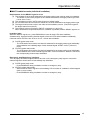
Operation flowchart
Mode switching operation table
Controller panel display
Mode name
How to switch from AUTO mode
AUTO
AUTO mode
Set by default when the power is turned on
*1
MNL
MNL flashing
*1
*2
*2
Manual (MNL) mode (EMISSION start)
Hold down MODE switch.
External manual (MNL) mode (External start)
Turn on the signal to INPUT terminal “MNL ON”
on the rear panel. (Cannot be switched to another
mode while MNL is flashing.)
ALL/MULTI
Irradiation mode
MNL mode + One press of MODE switch
PULSE/STATUS
Start signal mode
MNL mode + Two presses of MODE switch
X100hs
LED replacement time setting mode
MNL mode + Three presses of MODE switch
W/cm2
UV intensity measurement/calibration mode
MNL mode + Four presses of MODE switch
TYPE
Product type setting switch mode
MNL mode + Five presses of MODE switch
PROG
Program setting mode
MNL mode + Six presses of MODE switch
PWR
Power mode ON/OFF switch mode
MNL mode + Seven presses of MODE switch
In manual mode (EMISSION start), it is possible to externally start irradiation by turning on the external signal to “MNL ON”.
(MNL indicator will be turned on.)
In external manual mode (external start), it is possible to start irradiation by pressing EMISSION on the controller. (MNL
indicator will flash.)
Flowchart
Power on
AUTO
MNL
ALL/MULTI
PULSE/STATUS
X100hrs
Mode name
AUTO mode
(Page 19)
Manual (MNL) mode
(Page 23)
External MNL ON
Irradiation mode
External manual
(MNL) mode
(Page 26)
(Page 26)
Start signal mode
(Page 27)
LED replacement
time setting mode
(Page 27)
W/cm2
UV intensity
measurement/
calibration mode
(Page 28)
TYPE
Product type setting
switch mode
(Page 30)
PROG
Program setting
mode
(Page 30)
PWR
Power mode
ON/OFF switch
mode
(Page 32)
10
4 Installation
Install the ANUJ5024 Aicure under the conditions below.
4.1 Installation conditions
1) Ambient temp.: Main unit: 0 to 35°C
Head: 5°C to 35°C
2) Relative humidity: No greater than 85%, with no condensation
3) Make sure the rubber legs are set horizontally parallel.
4) In order to avoid damage due to overheating, do not use if the area
around the system is blocked.
5) The dimensions of the main unit are 80 mm (L) x 130 mm (H) x 145
mm (D), but you should take into account the state of the unit with
an LED head attached.
The minimum allowable bending radius for the LED head cord is 33
mm. Using the cord with a curve radius of less than 33 mm could
damage it.
Warning
Do not place items on top of the main unit, or block its air vents.
Excessive heat could damage the unit due to overheating.
Wall
Secure enough space
above and on the sides of
the controller.
Approx. 50 mm
Approx. 20 mm
Wall
Warning
Warning
When using more than one controller, do
not bundle the supplied AC adapters
together. The AC adapters may overheat
and damage the products.
*The power cable supplied with this
product is a 100VAC cable for use
in Japan only. When using this
product outside Japan, use a
power cable that has been
certificated by applicable
standards and has a plug shape
that fits the receptable used in each
country.
11
Installation
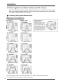
4.2 General guide for irradiation distance and UV intensity
Mount the LED head on the jig so that the irradiation distance is in accordance with the size of the
area to be irradiated (irradiation diameter) and the required UV intensity. Below is a general guide
for irradiation distance (WD) and UV intensity.
UV intensity data (Typical characteristics)
High power head: ANUJ6150
If an irradiation area of 6 mm diameter
is irradiated at an intensity of 500
mW/cm2 or higher, draw lines on the
graph at ±3 mm and 500 mW/cm2. Find
the irradiation distance line that covers
the area surrounded by the drawn lines.
In this example, the ANUJ61528 head
can maintain an intensity of 500
mW/cm2 or higher for a 6-mm diameter
area (in the power mode) by setting the
irradiation distance to 40 mm.
(Power mode)
Irradiation area (mm)
UV intensity (mW/cm2)
UV intensity (mW/cm2)
Irradiation area (mm)
Irradiation distance vs
intensity and area
UV intensity (mW/cm2)
Feedback mode
UV intensity (mW/cm2)
UV intensity (mW/cm2)
Power mode
Irradiation area (mm)
UV intensity (mW/cm2)
UV intensity (mW/cm2)
Irradiation area (mm)
Irradiation area (mm)
UV intensity (mW/cm2)
UV intensity (mW/cm2)
Irradiation area (mm)
Irradiation area (mm)
UV intensity (mW/cm2)
UV intensity (mW/cm2)
Irradiation area (mm)
Irradiation area (mm)
Irradiation area (mm)
[UV intensity level: 100% Room temperature: 25°C With a cooling device attached]
* See page 15 for the dimensions of the cooling device.
12
Irradiation
area (mm)
Installation
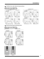
Cylindrical lens data (Typical characteristics)
High power head: ANUJ6150
Feedback mode
Power mode
UV intensity (mW/cm2)
Irradiation area (mm)
UV intensity (mW/cm2)
Irradiation area (mm)
Irradiation area (mm)
Width direction
Irradiation area (mm)
UV intensity (mW/cm2)
Irradiation area (mm)
UV intensity (mW/cm2)
Irradiation area (mm)
UV intensity (mW/cm2)
Length direction
UV intensity (mW/cm2)
Width direction
UV intensity (mW/cm2)
UV intensity (mW/cm2)
Length direction
Irradiation area (mm)
Irradiation area (mm)
Rod lens data (Typical characteristics)
Power mode
Feedback mode
UV intensity (mW/cm2)
UV intensity (mW/cm2)
High power head: ANUJ6150
UV intensity (mW/cm2)
Irradiation area (mm)
UV intensity (mW/cm2)
Irradiation area (mm)
Irradiation area (mm)
Cylindrical lens
Irradiation area (mm)
Rod lens
13
5 Getting started
After connecting the necessary cords, lastly plug in the power cord.
This section describes the steps up to turning on the power.
5.1 Hooking up the connection cable
Remove the caps on the connection-cable terminals, and hook up
the cables.
LED1
White
LED2
Red
LED3
Blue
LED4
Green
Note: Cable labels are affixed to the main unit. Please use them
if you want to identify the cables.
Connection cable
Warning
Plug the female side of the connection cable into the main unit.
Plugging in the wrong side (the male connector) could bend the
connector pins or cause other issues.
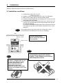
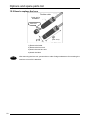
5.2 Connecting the LED
Connecting the head
LED head
Lens protector cap
Connector
Connection cable
Main unit side
LED side
Connector
14
Connector
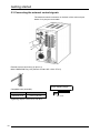
Getting started
Rear panel
<Procedure>
Connector
1 Remove the protective cap on the main unit
Protective cap
2
3
4
Plug in the connection cable.
Plug the connection cable into the LED head.
Remove the protective cap on the LED head.
Warning
Set the LED jig in place.
Reference: Cooling device (aluminum)
(100% output 15 sec ON – 15 sec OFF)
Note: The LED head is made of aluminum.
Care is required, because if you
tighten it directly with set screws
using too much strength when it is
secured in a jig, you may cause it to
deform.
No inner burrs
2-M4 (6mm D)
Warning
M6 (7mm D)
Note: LED can be used with a light-modulation
ratio of 100% or greater, by increasing
the size of the cooling device and/or
cooling the LED head.
Warning
If the LED head is not mounted on a jig, the LED head can become hot during irradiation.
For this reason, do not touch it directly with your hands during irradiation.
15
Getting started
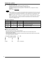
5.3 Connecting the external control signals
The external-control connectors on the back of the main unit (two
banks of 12 pins) are removable.
External control connectors (12 pins x 2)
MINI COMBICON Plug 12P (Phoenix Contact MC 1.5/12-ST-3.5)
Cover stripping length
Compatible wire (stranded)
Size
Conductor section area
AWG#24 to 16
0.2 to 1.25 mm2
Tightening torque: 0.22 Nm to 0.25 Nm
16
6 to 7 mm
Getting started
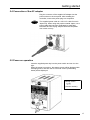
5.4 Connection of the AC adapter
Plug the connector of the supplied AC adapter into the
power socket on the rear panel. After installing the
controller, connect the power plug to a receptacle.
Warning
The supplied power cable is a 100 V AC cable for use in
Japan only. When using this product outside Japan, use a
power cable that has been certificated by applicable
standards and has a plug shape that fits the receptable
use in each country.
5.5 Power-on operation
Insert the supplied power key into the power switch and turn it to the
right.
When the power is turned on, the startup screen will be displayed with
a beeping sound, and then the AUTO mode screen (initial setting
status) will be displayed.
Startup screen
UJ 20
V *.**
(Version number)
17
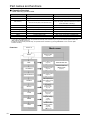
6 Operation modes
Mode displays
18
Operation modes
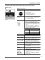
6.1 Auto mode (Set by default when the power is turned on)
Status check
Displays in AUTO mode
Display
Descriptions
EMISSION switch
Pressing it will start irradiation.
Stays on during irradiation.
READY
CH1 to 4
Indicates that irradiation is ready to start.
Stays on while irradiation is ready to start.
Stays off during irradiation.
Indicates the channel connection, irradiation
operation, and temperature warning.
Green: Indicates that the head is connected.
Orange: Indicates a temperature warning.
Red flashing: Indicates that irradiation is in
progress.
Flashes during irradiation, changing the
flashing speed depending on the detected
temperature of the LED head.
Flashing speed
LED head temperature
Off
No irradiation
Slow
Standard
Mid
Standard ≤ Temp. < Warning level
Quick
Warning level ≤ Temp. < Abnormal
ERROR
Lit when an error occurs.
PWR
Stays on while the power mode is on.
Display (2 digits)
Displays the product type no. (TYPE00 to
15) and the step no. (STEP 01 to 10).
Display (3 digits)
Displays the UV intensity level (0 to 100%),
LED head temperature (0 to 999), and
irradiation time (0 to 99.9, 100 to 999 sec.).
%
Stays on while the 3-digit display indicates
the UV intensity level.
sec.
Stays on while the 3-digit display indicates
the irradiation time.
x100hrs
Lit when the total irradiation time reaches
the warning point.
CH1 to 4
switches
Lit when the channel is selected.
Lit to indicate that the channel is selected for
the product type.
Flashes while the 3-digit display indicates
the STEP 1 data.
19
Operation modes
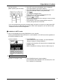
Status check
1) How to display the channel data
You can check the program (STEP 1 settings) and LED head temperature of the lit or flashing
channel.
(1) Switch the display
)
1. The three-digit display indicates the settings or LED head
temperature of the flashing channel.
2. If the channel indicator stays on, press it. It will flash, and
the three-digit display will indicate the settings and LED
head temperature.
3. Press UV PWR to display the UV intensity level (for STEP
1), and press it again to display the LED head temperature.
4. Press TIME to display the irradiation time (for STEP 1).
(You can switch the display even during irradiation. The
displayed values are saved in memory even after power-off,
and the latest displayed value will appear again after
power-on. Note that nothing will be displayed unless a
channel is selected.)
Displays the data of the flashing channel.
Warning
Displayed unit
%
sec.
None
Displayed value
UV intensity level
Irradiation time
LED head temperature
When a temperature is displayed, no unit symbol indicator is lit.
However, when a temperature warning is issued, x100hrs is
turned on.
2) How to display and set the total irradiation time (x100hrs)
You can check and clear (change) the total irradiation time of each channel.
)
READY is off while the total irradiation time is displayed.
(1) Switch the display to the total irradiation time screen.
1. Hold down TIME.
(To indicate the total irradiation time of CH1 on the
three-digit display)
2. Press the target channel switch.
(The total irradiation time of the channel will be indicated on
the three-digit display with the channel indicator lit.)
* Go to the next step to clear/change the time.
* Press MODE to go back to AUTO mode without
clearing/changing the time.
(2) Switch the channel.
20
Operation modes
(3) Clear the time.
(When replacing the LED head)
3. Press SET while the total irradiation time is displayed.
(The total irradiation time display flashes.)
4. Press T and S simultaneously to reset the value to zero.
(You can set another value by using T and S.)
5. Press
.
(To accept the changed value)
* Follow steps 1 to 5 above to clear/change the total
irradiation time of the other channels.
6. Hold down
or MODE.
(To save the total irradiation time settings in memory and go
back to AUTO mode)
* Press MODE to cancel the change without saving it in
memory and go back to AUTO mode.
* You can simultaneously accept the entered setting and save it in memory by holding down SET.
* When connecting an LED head that has been used in other equipment, you can enter its total
irradiation time for LED life management.
Irradiation in AUTO mode
1) How to start irradiation by pressing EMISSION on the controller
Pressing the EMISSION switch will start ALL mode irradiation in PULSE start mode regardless of
the selected irradiation modes.
(1) Start irradiation.
1. Press EMISSION.
(All lit channels will start irradiation, and the EMISSION
indicator will stay on during irradiation.)
* Irradiation will stop when all channels have completed their
irradiation steps.
* While a temperature warning is issued, x100hrs stays on.
)
Displays the data of the flashing channel.
(2) Make an emergency stop.
2. Press EMISSION again during irradiation.
[To immediately stop irradiation of all channels (Error code
E01: Irradiation uncompleted)]
21
Operation modes
2) How to start irradiation by an external signal input
Irradiation can be started by turning on the start signal input through INPUT terminals START 1 to
4 on the rear panel of the controller.
(1) Start irradiation.
1. Turn on the start signal.
(Irradiation will start under the conditions shown below.)
Mode
ALL
MULTI
Start mode
PULSE
STATUS
PULSE
STATUS
START1
{
z
{
z
INPUT terminal
START2 START3
−
−
−
−
{
{
z
z
START4
−
−
{
z
{ xxx Irradiation starts when the start signal is turned on.
z xxx Irradiation starts when the start signal is turned on, and
stops when turned off. (No error is issued for incomplete
irradiation.)
ALL mode:
All channels selected for the product type start
irradiation simultaneously when the START1
signal is turned on.
MULTI mode: The channel selected for the program starts
irradiation when the START signal with a
number corresponding to the channel number is
turned on.
(2) Make an emergency stop.
22
2. Turn on the STOP signal during irradiation.
[To immediately stop irradiation (Error code E01 “Irradiation
uncompleted” will be issued. Pressing EMISSION on the
controller also immediately stops irradiation.)]
Operation modes
6.2 Manual (MNL) mode
Hold down MODE to switch to the setting mode. Hold down MODE again to return to AUTO mode.
You can also switch the mode to MNL by turning on the external MNL ON signal while the
controller is in AUTO mode. (When the mode is switched by the external signal, the MNL
indicator will flash.)
Displays in MNL mode
Display
Descriptions
EMISSION switch
Pressing it will start irradiation.
Stays on during irradiation.
READY
)
Displays the data of
the flashing channel.
CH1 to 4
Indicates that irradiation is ready to start.
Stays on while irradiation is ready to start.
Stays off during irradiation.
Indicates the channel connection, irradiation
operation, and temperature warning.
Green: Indicates that the head is connected.
Orange: Indicates a temperature warning.
Red flashing: Indicates that irradiation is in
progress.
Flashes during irradiation, changing the
flashing speed depending on the detected
temperature of the LED head.
Flashing speed
LED head temperature
Off
No irradiation
Slow
Standard
Mid
Standard ≤ Temp. < Warning level
Quick
Warning level ≤ Temp. < Abnormal
ERROR
Lit when an error occurs.
PWR
Stays on while the power mode is on.
Display (3 digits)
Displays the UV intensity level (0 to 100%),
LED head temperature (0 to 999), and
irradiation time (0 to 99.9, 100 to 999 sec.).
%
Stays on while the 3-digit display indicates
the UV intensity level.
sec.
Stays on while the 3-digit display indicates
the irradiation time.
x100hrs
Lit when the total irradiation time reaches
the warning point.
CH1 to 4
switches
Lit when the channel is selected.
(You can select the channels with an LED
head connected.)
23
Operation modes
Operation
1) How to display the channel data
You can check channel data with an LED head connected (UV intensity level, irradiation time, and
LED head temperature).
(1) Switch to MNL mode.
(2) Switch the displayed channel.
)
)
Displays the data of the flashing channel
You can select the channels with an LED
head connected
1. Hold down MODE.
(The MNL indicator will be turned on.)
2. Press the target channel switch with an LED head
connected.
(The channel switch indicator will flash, and the
three-digit display will indicate the channel data.)
3. Press UV PWR.
(The UV intensity level and the LED head temperature
will be displayed.)
4. Press TIME.
(The irradiation time will be displayed.)
* The displayed irradiation time is the manual irradiation
time. Switch the mode or power off the controller to turn
off the time display.
*The latest setting of the UV intensity level is saved in
memory.
*You can switch the display even during irradiation. The
displayed values are saved in memory even after
power-off, and the latest displayed value will appear
again after power-on. Note that nothing will be displayed
unless a channel is selected.)
Displayed unit
%
sec.
None
Warning
Displayed value
UV intensity level
Irradiation time
LED head temperature
When a temperature is displayed, no unit symbol
indicator is lit. However, when a temperature warning is
issued, x100hrs is turned on.
2) How to change channel data with an LED head connected
You can change the channel data with an LED head connected.
(1) Switch to MNL mode.
(2) Select the channel.
24
1. Hold down MODE.
2. Press the target channel switch with an LED head
connected.
(The channel will be selected with its indicator flashing, and
the three-digit display will indicate the channel data.)
Operation modes
(3) Clear the channel selection.
(4) Set the UV intensity level.
)
Displays the data of the flashing
channel.
3. Press the flashing channel switch.
(The channel selection will be cleared, and the channel
switch indicator will be turned off.)
4. Press UV PWR to go to the UV intensity level screen
with the % indicator lit.
5. Press T and S to adjust the intensity level.
(The displayed UV intensity level will flash.)
6. Press SET.
(The UV intensity level setting will be accepted, and the
display will stay on.)
* You can change the intensity level even during
irradiation.
■ Irradiation in MNL mode
1) How to start irradiation by pressing EMISSION on the controller
Hold down MODE to switch to the setting mode. Press EMISSION, and all selected channels will
start irradiation simultaneously. The EMISSION indicator stays on during irradiation.
Press EMISSION during irradiation, and all channels will stop irradiation.
(1) Switch to MNL mode.
(2) Select the channel.
(3) Set the UV intensity level.
(4) Start irradiation.
)
1. Hold down MODE.
2. Press the channel switch.
3. Press T and S to adjust the intensity level.
4. Press SET.
5. Press EMISSION.
(All lit channels will start irradiation, and the EMISSION
indicator will stay on during irradiation.)
Displays the data of the flashing
channel.
(5) Stop irradiation.
6. Press EMISSION during irradiation.
(All channels will stop irradiation.)
* While a temperature warning is issued, x100hrs stays on.
* While one or more channels are in the midst of the irradiation process, you can start irradiation
of the other channels with an LED connected that is not in irradiation process by turning on the
switch of the channel. In this case, the irradiation time display is cleared and newly counted
every time irradiation starts.
* Irradiation by individuals channels can be stopped by pressing the flashing channel switch
again (whose data is displayed).
* When all channels stop irradiation, the EMISSION indicator is turned off.
25
Operation modes
2) How to start MNL irradiation by an external signal input
Irradiation can be started by turning on the start signal input through INPUT terminals START 1 to
4 on the rear panel of the controller.
(1) Switch to external MNL mode.
(2) Start irradiation.
(3) Stop irradiation.
1. Turn on the signal input to INPUT terminal “MNL ON”
on the rear panel of the controller.
(The MNL indicator will flash.)
2. Turn on the signal input to the START terminal with the
number corresponding to the target channel number.
(Irradiation will start. The EMISSION indicator on the
controller stays on during irradiation.)
3. Turn off the signal to the START terminal for the
irradiating channel.
(Irradiation will stop.)
* While a temperature warning is issued, x100hrs stays on.
* Switching to the external MNL mode is only available from the AUTO or MNL mode.
* When the MNL ON signal is turned off, the controller will return to the previous mode (AUTO or
MNL).
* When the MNL ON signal is turned on in AUTO mode to switch to external MNL mode, the MNL
indicator will flash.
6.3 Irradiation mode (ALL/MULTI)
Press MODE once in MNL mode to go to the irradiation mode setting screen.
The current mode indicator will be turned on.
Setting
(1) Switch the mode.
)
26
1. Press SET.
(To switch between ALL and MULTI)
* Available in AUTO mode.
* ALL mode: All channels are selected simultaneously
for the product type start irradiation when the START1
signal is turned on.
* MULTI mode: The channel selected for the program
starts irradiation when the START signal with a
number corresponding to the channel number is
turned on.
Pressing the EMISSION switch on the controller will always start ALL mode irradiation in PULSE start mode.
Operation modes
6.4 Start signal mode (PULSE/STATUS)
Press MODE twice in MNL mode to go to the start signal mode setting screen.
The current mode indicator will be turned on.
Setting
(1) Switch the mode.
)
1. Press SET.
(To switch between PULSE and STATUS)
* Available in AUTO mode.
* PULSE mode: Irradiation starts when the start signal
is turned on. (Pulse width: 100 ms or more)
* STATUS mode: Irradiation starts when the start
signal is turned on, and stops when turned off.
Pressing the EMISSION switch on the controller will always start ALL mode irradiation in PULSE start mode.
6.5 LED replacement time (x100hrs) setting mode
Press MODE three times in MNL mode to go to the LED replacement time setting screen. Then
press SET to display the current replacement time setting.
Setting
(1) Set the LED replacement time
1. Press SET.
(The LED replacement time setting will be displayed.)
2. Press T and S to change the setting.
(The display flashes during the changing operation.)
3. Press SET.
(The setting will be accepted, and the display will stay
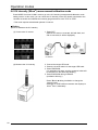
on.)
4. Hold down SET.
(To save the setting in memory, clear the display, and
return to the top of the setting screen)
* Press MODE to cancel the change without saving it in
memory and return to the top of the setting screen.
* You can simultaneously accept the entered setting
and save it in memory by holding down SET rather
than pressing it in step 3 above.
27
Operation modes
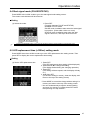
6.6 UV intensity (W/cm2) measurement/calibration mode
Press MODE four times in MNL mode to go to the UV intensity measurement/calibration mode
setting screen. In this mode, you can check the UV intensity of the LED heads connected to the
controller channels and calibrate the intensity programmed for each TYPE or STEP.
* This mode requires a dedicated optional UV sensor.
Setting
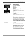
1) How to measure the UV intensity
(1) Connect the UV sensor.
1. Press SET.
(Without the sensor connected, 000 will flash, and
with it connected, 0 will be displayed.)
UV Sensor
(2) Measure the UV intensity.
2. Connect the target LED head.
3. Press the channel switch for the target LED head.
4. Press EMISSION.
(UV irradiation will start, and the measured value will
be indicated on the three-digit display.)
5. Press EMISSION during irradiation.
(Irradiation will stop.)
* Press T and S during irradiation to change the
intensity level.
* Pressing UV PWR switches between the displays in
W/cm2 and % alternately.
28
Operation modes
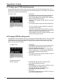
2) How to calibrate the UV intensity
(1) Switch to the calibration mode.
(2) Start calibration.
1. Connect the UV sensor.
2. Hold down SET.
(The two-digit display will flash.)
3. Press T and S to select the target TYPE number.
4. Press SET.
(To accept the TYPE number and go to the STEP
setting screen.)
5. Press T and S to select the target STEP number.
6. Press SET.
(To accept the STEP number and go to the UV
intensity setting screen.)
7. Press T and S to select the target UV intensity
(W/cm2).
8. Press SET.
(The target UV intensity setting will be accepted, and
the display will stay on.)
9. Press the channel switch for the LED head to be
calibrated.
10. Press EMISSION.
(Irradiation will automatically start and stop after
completion.)
* The measured intensity (W/cm2) and the intensity
level (%) are displayed alternately during calibration.
* When calibration has completed, the measured
intensity after calibration (W/cm2) will be displayed.
Pressing UV PWR will alternately display the target
UV intensity (W/cm2) and the intensity level after
calibration (%).
* Pressing EMISSION again during irradiation will stop
irradiation, issuing error E07.
(3) End calibration.
11. Press SET.
(To accept and set the calibrated value for the
program)
* You can continue to calibrate the intensity for the
other TYPE number.
* Hold down SET to save the calibrated value in
memory and return to the UV intensity
measurement/calibration (W/cm2) mode.
* Press MODE to cancel all data and return to the UV
intensity measurement/calibration (W/cm2) mode.
29
Operation modes
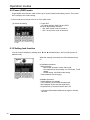
6.7 Product type (TYPE) switching mode
Press MODE five times in MNL mode to go to the product type (TYPE) switching screen. Then
press SET to display the current product type and channel selections. In this mode, you can switch
the product type and channel selections.
(1) Switch TYPE.
1. Press SET.
(To display the current type and channel selections)
2. Press T and S to select the target product type.
(The two-digit display and channel switch will flash.)
3. Select the target channel switch.
(Press the lit or flashing channel switch to cancel the
selection.)
4. Press SET.
(To accept the product type and channel selections.)
* You can change the channel selection by pressing
the target channel switch.
Press SET to accept the channel selection change.
* Hold down SET to save the selection in memory and
return to the product type switching screen.
* Press MODE to cancel the change and return to the
product type switching screen.
6.8 Program (PROG) setting mode
Press MODE six times in MNL mode to go to the program (PROG) setting screen. Then press SET
to display the current product type and channel selections. In this mode, you can set up to ten
AUTO irradiation program steps (STEP 1 to 10) for each channel for each product type. (Only
STEP 1 can be set for TYPE 00.)
(1) Select TYPE.
(2) Select the channel.
(3) Set a program.
30
1. Press SET.
(To display the current type and channel selections)
2. Press T and S to select the target product type.
(The two-digit display will flash.)
3. Press the switch of the channel to be programmed.
* When selecting two or more channels, press two or
more channel switches simultaneously.
4. Press SET.
(To accept the type and channel selections and go to
the STEP setting screen.)
5. Press T and S to set the UV intensity level.
(The three-digit display will flash.)
6. Press SET.
(To accept the UV intensity level for STEP 01 and go
to the irradiation time setting screen.)
7. Press T and S to set the irradiation time.
(The three-digit display will flash.)
8. Press SET.
(To accept the irradiation time for STEP 01 and go to
the STEP 02 setting screen.)
Operation modes
* When you finish programming STEP 01 to 10 by following 5 to 8 above, program setting for the
other channels will be available. Start from the channel selection step and follow the same
procedures.
* Hold down SET to save all entered programs in memory.
* Press MODE to cancel the changes without saving them in memory and return to the program
setting screen.
* If AUTO irradiation does not require all ten program steps, set the irradiation time for the next step
of the last required step to 0 sec. to end the program setting without going to the next step and
go back to the top of the program setting screen. (For example, when only STEP 1 and 2 need to be
programmed, set the irradiation time for STEP 3 to “0 sec.” With this setting, AUTO irradiation will
end after completing STEP 2.)
* If you hold down SET during the program setting, all entered data will be accepted and saved in
memory simultaneously.
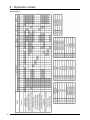
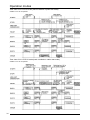
Program table
TYPE
STEP2
% sec
STEP3
% sec
STEP4 STEP5
% sec % sec
STEP6
% sec
STEP7
% sec
STEP8
% sec
STEP9 STEP10
% sec % sec
Only STEP 1 can be set for TYPE 00 (Simple mode).
∼
CH1
CH2
00
CH3
CH4
CH1
CH2
01
CH3
CH4
STEP1
% sec
CH1
CH2
15
CH3
CH4
31
Operation modes
6.9 Power (PWR) mode
Press MODE seven times in MNL mode to go to power (PWR) mode setting screen. Then press
SET to display the current setting.
* Power mode can be turned on/off in AUTO or MNL mode.
(1) Switch the setting.
1. Press SET.
(To switch between PWR ON and OFF.)
The three-digit display indicates
* ON” when power mode is turned on
* OFF” when power mode is turned off
6.10 Setting lock function
You can lock the settings by holding down T and S simultaneously in AUTO mode (power-on
default mode).
While the settings are locked, the LOCK indicator stays
on.
Unavailable operations
- Mode switching
- MNL mode, operation mode, start mode,
- LED replacement time setting, UV CHK mode, TYPE
setting,
- PROG setting, and PWR mode setting
- Total irradiation time changing
Available operations
- Total irradiation time display
- TYPE switching by an external signal input
- NNL operation by an external signal input
- All operations by communications with a PC
* Hold down T and S simultaneously again to release
the lock.
32
Operation modes
6.11 Irradiation mode setting
ALL irradiation mode (batch irradiation)
Requirements for the READY signal to be on
(1) The programs of all channels selected for the target product type must be ready for irradiation.
- The STEP 01 time of the programs of all channels selected for the target product type must
not be set to “0 sec.”
(2) The controller must be in AUTO mode (power-on default mode).
(3) LED heads must be connected to all channels selected for the target product type.
(4) The target channels must not be in the midst of the irradiation process. (The BUSY signals of
the target channels must be off.)
(5) The interlock must be functioning. [INPUT connectors (11) and (12)]
When all of the above requirements are met, irradiation is possible, and the READY signal will
be on.
Irradiation start
When the READY signal is on, press EMISSION or input the following external signal to start
irradiation.
(1) PULSE (pulse start) mode:
: The LED heads connected to all channels selected for the target product type start
irradiation at the leading edge of external signal “START 1” (100 ms or more)
simultaneously.
(2) STATUS (status start) mode:
: The LED heads connected to all channels selected for the target product type start
irradiation when external signal “START 1” is turned on, and stop irradiation when the signal
is turned off.
Emergency stop/Stop during irradiation
Turn off (open) the external signal interlock and turn on the emergency stop signal, or control the
external signal as shown below, to immediately stop irradiation.
(1) PULSE (pulse start) mode:
: Press EMISSION during irradiation to make an emergency stop.
: The ON/OFF status of other start signals START 2, 3, and 4 is ignored.
(2) STATUS (status start) mode:
: When START 1 is turned off during irradiation, irradiation will be stopped (with no error
issued).
: Press EMISSION during irradiation to make an emergency stop.
: The ON/OFF status of other start signals START 2, 3, and 4 is ignored.
33
Operation modes
Time chart of ALL-PULSE mode (batch irradiation in pulse start mode)
START 2 to 4 do not operate.
Time chart of ALL-STATUS mode (batch irradiation in status start mode)
START 2 to 4 do not operate.
34
Operation modes
MULTI irradiation mode (individual irradiation)
Requirements for the READY signal to be on
(1) The program of the channel selected for the target product type must be ready for irradiation.
- The STEP 01 time of the program of the channel selected for the target product type must
not be set to “0 sec.”
(2) The controller must be in AUTO mode (power-on default mode).
(3) An LED head must be connected to at least one channel selected for the target product type.
(4) The target channel must not be in the midst of the irradiation process. (The BUSY signal of
the target channel must be off.)
(5) The interlock must be functioning. [INPUT connectors (11) and (12)]
When all the above requirements are met, irradiation is possible, and the READY signal is on.
Irradiation start
When the READY signal is on, press EMISSION to have all ready LEDs start irradiation
simultaneously. Input the following external signal to have the LEDs start irradiation individually.
Channels whose STEP 01 time is set to “0 sec.” will not start irradiation.
(1) PULSE (pulse start) mode:
: The LED heads connected to the channels selected for the target product type individually
start irradiation at the leading edge of each external signal “START 1/2/3/4” (100 ms or
more).
(2) STATUS (status start) mode:
: The LED heads connected to the channels selected for the target product type individually
start irradiation when each external signal START 1/2/3/4 is turned on. When it is turned off,
the corresponding channel stops irradiation.
Emergency stop/Stop during irradiation
Turn off (open) the external signal interlock and turn on the emergency stop signal or control the
external signal as shown below to immediately stop irradiation.
(1) PULSE (pulse start) mode:
: Press EMISSION during irradiation to make an emergency stop.
(2) STATUS (status start) mode:
: When external START signal for the irradiating LED is turned off, irradiation will be stopped
(with no error issued).
: Press EMISSION during irradiation to make an emergency stop.
35
Operation modes
Time chart of MULTI-PULSE mode (individual irradiation in pulse start mode)
The channels individually start irradiation by turning on START 1 to 4 respectively.
Time chart of MULTI-STATUS mode (individual irradiation in status start mode)
The channels individually start irradiation by turning on START 1 to 4 respectively.
36
7 External control
7.1 External input/output control
External control connectors (12 pins x 2)
MINI COMBICON Plug 12P
(Phoenix Contact MC 1.5/12-ST-3.5)
Compatible wire (stranded)
Size
AWG#24 to 16
Warning
Cover stripping length
Conductor section area
2
0.2 to 1.25 mm
6 - 7 mm
Tightening torque: 0.22 Nm to 0.25 Nm
Precautions for wiring
- Carefully strip the cover so as not to damage the core wires.
- Connect the core wires without twisting them.
- Connect the core wires without soldering them; otherwise, they may break due to
vibration.
- After connection, do not apply stress to the cable.
- Because of the terminal structure, if the wire is tightened by a counterclockwise rotation,
the connection will fail. In such cases, pull out the wire, check the terminal hole, and then
connect it again.
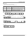
Input/Output terminal table
INPUT
Pin No.
1
2
3
4
5
6
7
8
9
10
11
12
Signal name
START 1
START 2
START 3
START 4
TYPE Chg1
TYPE Chg2
TYPE Chg4
TYPE Chg8
STOP
MNL ON
EMER.
COM
Descriptions
CH1 or batch irradiation start signal
CH2 irradiation start signal
CH3 irradiation start signal
CH4 irradiation start signal
Product type switching signal
Product type switching signal
Product type switching signal
Product type switching signal
Emergency irradiation stop signal
Manual mode switch signal (External MNL mode)
Interlock (normally ON)
Common terminal for input/output signals
Signal name
READY
BUSY 1
BUSY 2
BUSY 3
BUSY 4
ERROR
ALARM
COM
COM
FG
+5V
GND
Descriptions
ON when irradiation is ready to start
ON during CH1 irradiation
ON during CH2 irradiation
ON during CH3 irradiation
ON during CH4 irradiation
Error signal
Warning signal (temperature/time warning)
Common terminal for input/output signals
Common terminal for input/output signals
Frame ground
5 V DC output (for display or output signals)
5 V DC ground
OUTPUT
Pin No.
13
14
15
16
17
18
19
20
21
22
23
24
Warning
The ON time of the input signal pulses must be 100 ms or more.
37
External control
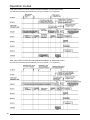
Product type switch table
TYPE No.
Pin No. 8
Pin No. 7
Pin No. 6
Pin No. 5
00
off
off
off
off
01
02
03
04
05
06
07
08
09
10
11
12
13
14
15
off
off
off
off
off
off
off
on
on
on
on
on
on
on
on
off
off
off
on
on
on
on
off
off
off
off
on
on
on
on
off
on
on
off
off
on
on
off
off
on
on
off
off
on
on
on
off
on
off
on
off
on
off
on
off
on
off
on
off
on
Remarks
All off: Controller operation
has priority.
When an external signal is on,
the product type set by the
external signal has priority.
Control by external signals
Input specifications
Contact input
Foot switch
Non-contact input
Tr output from PLC
Open collector (Tr) or no-voltage
input such as a relay
Output specifications
With external power
supply
With internal power
supply
Rated operation voltage: 5 to 24 V DC
Output capacity: 100 mA (max.)
Output specifications
-Rated load voltage: 5 V DC to 24 V DC
-Maximum allowable load current: 100 mA (per output)
When using the internal 5 V power supply, the maximum allowable
load current is 250 mA in total.
-Maximum voltage drop in ON state: 0.9 V
38
External control
7.2 Serial communication control
RS232C terminal specifications
(D-Sub 9-pin)
D-Sub 9-pin (male) connector (DELC-J9PAF-10L9E made by JAE)
[Connection cable specifications]
Use a D-Sub 9-pin (female) connector.
Straight cable
Signal
Not assigned
Send data
Receive data
Not assigned
Signal ground
Not assigned
Not assigned
Not assigned
Not assigned
Abbr.
Pin No.
SD
RD
SG
-
1
2
3
4
5
6
7
8
9
Communication specifications
Interface
Communication method
Synchronization
Transmission medium
Transmission distance
Transmission speed
Transmission code
Transmission format
RS232C
Half duplex
Asynchronous communication method
3-core shielded wire
15 m max.
38400bps
ASCII
Data length: 8 bits
Parity check: None
Stop bit: 1 bit
39
External control
Commands and responses
- Instructions sent to the controller are called commands.
- Messages returned from the controller are called responses.
- The communications are two-way. (When a command is sent, a response is always
returned.)
- Data is sent in ASCII format.
Warning
- When a response is not received, this indicates that the transmission format is wrong, the
command has not yet reached its destination, or the controller is not in operation. Check
the communication specifications, such as the transmission speed, data lengths, and
parity.
When a response with “!” instead of “$” stored is received, it indicates that the command
has not been processed correctly. Check the communication error code stored in the
response to identify the error.
Control commands
Name
Header
Command
Response
(Normal)
Response
(Error)
Terminator
Character
<
#
ASCII
3CH
23H
Descriptions
Beginning of the message
Command message
$
24H
Normal response message
!
21H
Error response message
CR
0DH
End of the message
Block check code BCC (H) (L)
Two-digit hexadecimal number: 00 to FF (ASCII)
- BCC are codes used for horizontal parity check to detect errors for improvement of the
transmission data reliability.
- BCC are made up of two ASCII characters converted from eight-bit data of XOR from the header
(<) to the last character of the text.
40
< 01 # RD D 05010 05010
4C
Header
BCC: 2 characters
Text
CR
External control
Error codes
Two-digit hexadecimal number: 00 to FF (ASCII)
- When an error occurs, the codes are sent to identify the error.
Error code
Error name
40H
BCC error
41H
Format error
45H
Address error
Descriptions and troubleshooting
The command data caused a BCC error.
<Troubleshooting> Check the BCC code and resend the
data.
For example, the transmission format of the command
data is not correct, or the address does not exist.
<Troubleshooting> Correct the format or command.
The sent address was outside the range.
<Troubleshooting> Check the address.
Command/response format
<
Command or
Response
1
0
Text
BCC
CR
Reading
Command
<
0
1
#
R
D
D
Initial address (5 Characters)
3
x104
2
1
x10
x10
x10
BCC
Final address (5 characters)
0
x10
x104
3
2
x10
x10
1
x10
0
x10
1
x16
CR
0
x16
Normal response
<
0
1
$
R
D
Read data (initial)
1
x16
0
x16
(Lower)
3
x16
x16
(Higher)
BCC
Read data (final)
2
1
x16
0
x16
(Lower)
3
x16
2
x16
1
x16
CR
0
x16
(Higher)
Error response
<
0
1
!
Error code
1
x16
0
x16
CR
BCC
1
x16
0
x16
41
External control
Writing
Command
<
0
1
#
W
D
D
Initial address (5 Characters)
4
3
x10
2
x10
1
x10
Final address (5 characters)
0
x10
x10
4
x10
3
2
x10
Write data (initial)
4 characters
1
0
x16
x16
3
x16
<
0
1
$
W
D
BCC
CR
1
0
x16
Error response
<
0
1
!
Error code
1
x16
0
x16
CR
BCC
1
x16
0
x16
Utility software (for control from a PC)
- Download the software from our website.
- The software is compatible with Windows XP.
42
x16
(Higher)
x16
0
x10
x10
Write data (final)
4 characters
2
(Lower)
Normal response
1
x10
1
x16
0
x16
(Lower)
3
x16
CR
BCC
2
x16
(Higher)
1
x16
0
x16
8 Warning Displays
In the event of an error during irradiation, the AUTO or MNL mode screen will display a warning.
Temperature warning
When the LED head temperature reaches the warning level during irradiation in MNL or AUTO
mode, the channel connection indicator will change to orange (mixture of green and red) and the
external output signal “ALARM” will be turned on.
Temperature warning
When the measured LED head temperature reaches the
warning level, the channel connection indicator will stay on and
remain orange. When the temperature reaches an abnormal
level, error code E05 will be displayed with a beeping sound,
and external output signal ERROR will be turned on. The
warning indicator will change to green when the temperature
has decreased to the level where the warning is cleared. If the
color does not change to green after waiting for a while, it Is
possible that there is a problem with the LED temperature
detection line, such as a short-circuit. Remove the LED head
and the connection cable from the connector and check the
wiring.
Time warning
When the total irradiation time reaches the warning point during irradiation in MNL or AUTO mode,
unit indicator “x100hrs” will be turned on, and the external output signal ALARM will be turned on.
After the time warning is issued, x100hrs always stays on until the total irradiation time is reset in
AUTO or MNL mode.
Time warning
When the total irradiation time of the LED head reaches 30
hours before the LED replacement point, x100hrs will be turned
on. When the time reaches the LED replacement point, error
code E06 will be displayed with a beeping sound, and the
external output signal ERROR will be turned on. Holding down
SET will forcibly reset the error and turn off the external output
signal ERROR with a beeping sound. However, the ERROR
indicator will still stay on. The indicator will be turned off when
the total irradiation time is reset after the LED head
replacement.
If irradiation continues while the ERROR indicator stays on,
error code E06 will be displayed again with a beeping sound.
* You can check which channels are under the time warning by
switching the display to the total irradiation time (x100hrs)
screen. If x100hrs indicator is flashing, the channel is under
the time warning.
43
Warning Displays
Error codes
When an error occurs, the three-digit display will indicate the error code.
Display
Error name
Descriptions
E00
Interlock emergency stop
The interlock contact was opened during
irradiation.
E01
Irradiation incomplete
The irradiation was stopped before
completion.
E02
Connection error
E03
LED wire broken
E04
LED short-circuited
LED short-circuiting was detected during
irradiation.
E05
LED temperature error
The LED temperature reached an abnormal
level.
E06
LED time error
The total irradiation time reached the
replacement point.
E07
Calibration error
The UV intensity did not reach the set
intensity.
E08
E09
E10
E11
E12
E13
E14
E15
44
Disconnected during irradiation
LED circuit opening was detected during
irradiation.
9 Safety Measures
9.1 Safety circuit
Aicure UJ20 is equipped with a safety circuit, which functions as follows, in case of a malfunction or
accident.
1) f the cable between the LED head and the controller is broken, an error signal will be output and
an error screen displayed.
2) If the LED head is short-circuited, an error signal will be output and an error screen displayed.
3) If the LED head temperature becomes excessively high, a warning signal will be output with a
warning screen displayed.
4) If 5 V and GND are shorted by mistake during external terminal connections, the 5 V circuit will
stop operation. When the short circuit is removed, the controller will automatically recover. Note,
however, that if the short-circuited state lasts for an extended period, this product may be
damaged.
45
10 Specifications
Overall specification
y Head specification
Part No. (Head alone)
ANUJ6150 High power head
φ3
φ4
φ6
φ8
φ10
Part No.
ANUJ
ANUJ
ANUJ
ANUJ
ANUJ
(lens alone)
6423
6424
6426
6428
6420
ANUJ
ANUJ
ANUJ
ANUJ
ANUJ
61523
61524
61526
61528
61520
Spot dia. (mm)
High power head
Applicable lens
Head/lens set part No.
Head block part No. Lens/lens/cable set
2
Irradiation Intensity(mW/cm )*1
Irradiation distance (mm)
Standard head
ANUJ
ANUJ
61528C
61520C
8000
mW/cm
6850
2
mW/cm
2990
2
12mm
mW/cm
580
1740
2
20mm
mW/cm
2
25mm
mW/cm
30mm
Class-3B
ANUJ6140 (Standard head)
φ3
φ4
φ6
φ8
φ10
Part No.
ANUJ
ANUJ
ANUJ
ANUJ
ANUJ
(lens alone)
6423
6424
6426
6428
6420
ANUJ
ANUJ
ANUJ
ANUJ
ANUJ
61423
61424
61426
61428
61420
Head/lens set part No.
Head block part No. Lens/lens/cable set
2
Irradiation Intensity(mW/cm )*1
Irradiation distance (mm)
LED lamp
ANUJ
ANUJ
ANUJ
ANUJ
ANUJ
61423C
61424C
61426C
61428C
61420C
4000
mW/cm
3250
2
10mm
mW/cm
12mm
1530
2
mW/cm
20mm
260
850
2
mW/cm
2
25mm
Max. output: 150 mW; Wavelength:365 ±5 nm;
mW/cm
2
30mm
Class-3B
LED system
Estimated LED lamp life
20,000 hours (LED head temp. at 65ºC, max)
Operation temp. / humid. range
Controller: 5 to 35ºC, max. 85% (no condensation)
Storage temp. / humid. range
Controller: -10 to 60ºC, max. 85% (no condensation)
* 1: In power mode
2
LED system
Spot dia. (mm)
High
power/Standard
ANUJ
61526C
Max. output: 330 mW; Wavelength:365 ±5 nm;
Part No. (Head alone)
46
ANUJ
61524C
10mm
LED lamp
Applicable lens
ANUJ
61523C
Specifications
y Controller
UJ20 controller product No.
Connectable heads
Connectable UV sensor
UV irradiation
Type switching
Intensity/irradiation control
Setting/Operation
Display
Ports
External
control
External input
External output
Operating voltage
Ambient temperature/
humidity range
Storage temperature/
humidity
ANUJ5024 (with AC adapter)
1 to 4 heads
1 sensor (ANUJ6100 optional dedicated UV sensor)
One program for Simple Mode and up to 15 user-definable programs
(up to 10 steps each)
The heads are collectively/individually controllable.
Up to 16 irradiation programs can be stored and switched by external
signals.
Digital intensity and irradiation control
Manual/timer control (0.1 to
999 sec.)
Calibration function using the optional sensor for UJ20 only
Setting by the operation switches
Power key switch
Large color-switching LED display
Large seven-segment LED display
RS232C parallel I/O
Individual irradiation input, emergency stop input, interlock,
full-irradiation input, manual irradiation switching, and product type
switching
READY signal, error signal, warning output, BUSY output (each head
separately), and +5 V output (for indicators)
Supplied AC adapter: 100 to 240 V AC (±10%), 50/60 Hz, 60 VA (at
100 V AC)
Controller: 0 to 35°C, 85% max. (No condensation)
Controller: -10 to 60°C, 85% max. (No condensation)
47
11 Dimensions
z Controller (Weight: 1.0 kg)
ANUJ5024
(Unit: mm)
Excluding the projecting parts.
z Normal lens
Cylindrical lens
z Head
Standard lens
LED head
Openign
diameter:
Approx. 35
z Connection cable
z Rod lens
ANUJ6220
Connector
z UV sensor
Connector
ANUJ6100
Connector
z Head mounting
bracket
M4 (LED setting screw)
2-M4 Depth 6
M6 Depth 7
48
(Aluminum)
12 Options and spare parts list
12.1 Product numbers for placing orders
z Main units
Specification
UJ20 Controller (with AC adapter)
With 3-mm dia. lens
With 4-mm dia. lens
With 6-mm dia. lens
With 8-mm dia. lens
With 10-mm dia. lens
With 3-mm dia. lens
With 4-mm dia. lens
With 6-mm dia. lens
With 8-mm dia. lens
With 10-mm dia. lens
High power
Item
Controller
Standard
Head unit
(Head, lens, and 1.7 m cable)
Product No.
ANUJ5024
ANUJ61523C
ANUJ61524C
ANUJ61526C
ANUJ61528C
ANUJ61520C
ANUJ61423C
ANUJ61424C
ANUJ61426C
ANUJ61428C
ANUJ61420C
z Options
Item
UV sensor
Goggles
Mounting bracket
Specification
UV sensor for UJ20 only
UV protective goggles
Head mounting bracket
Product No.
ANUJ6100
ANUP5001SG
ANUJ6801
z Special lens (made to order)
Item
Specification
Cylindrical R5
Cylindrical R7.5
4-mm dia., R7, L = 43 mm
6-mm dia., R7, L = 43 mm
Cylindrical lens
Rod lens
Product No.
ANUJ6450S
ANUJ6475S
ANUJ6447L
ANUJ6467L
z Spare parts (unit components)
Specification
With 3-mm dia. lens
With 4-mm dia. lens
With 6-mm dia. lens
With 8-mm dia. lens
With 10-mm dia. lens
With 3-mm dia. lens
With 4-mm dia. lens
With 6-mm dia. lens
With 8-mm dia. lens
With 10-mm dia. lens
High power head
Standard head
3-mm dia. lens
4-mm dia. lens
6-mm dia. lens
8-mm dia. lens
10-mm dia. lens
1.7 m Cable diameter: 5.5 mm
3.0 m (made to order) Cable diameter: 5.5 mm
5.0 m (made to order) Cable diameter: 7.6 mm
7.0 m (made to order) Cable diameter: 7.6 mm
10.0 m (made to order) Cable diameter: 7.6 mm
Adapter for UJ20 only: 100 to 240 V AC
High power
Item
Standard
Head with lens
Head only
Lens unit
Connection cable
AC adapter
Product No.
ANUJ61523
ANUJ61524
ANUJ61526
ANUJ61528
ANUJ61520
ANUJ61423
ANUJ61424
ANUJ61426
ANUJ61428
ANUJ61420
ANUJ6150
ANUJ6140
ANUJ6423
ANUJ6424
ANUJ6426
ANUJ6428
ANUJ6420
ANUJ6220
ANUJ6230
ANUJ6250
ANUJ6270
ANUJ6200
ANUJ6802
49
Options and spare parts list
12.2 How to replace the lens
Flexible cable
Guide slit for
installation
Lens unit
(Unit: mm)
1) Remove the label.
2) Remove the lens unit.
3) Attach the new lens unit.
4) Attach the label.
Warning
After removing the lens unit, prevent dust or other foreign substances from entering the
new lens unit until it is attached.
50
13 Troubleshooting
Symptoms
LED does not irradiate.
Checks/Remedies
Did you select the target channel for the product type? (When selected, the
channel switch is lit or flashing.)
Æ Select the target channel when setting the product type.
If the target channel is selected but does not irradiate, check if the UV
intensity level is set to 0% for the channel program for the target product
type.
Æ If so, set the UV intensity level to 1% or higher.
When a warning message is displayed:
Temperature warning
The channel connection indicator changes to orange (mixture of green and
red) when the LED head temperature has reached the warning level. If you
continue the operation in this condition, the product life will be significantly
shortened, and the temperature may exceed the upper limit, causing an
emergency stop.
Æ Set the UV intensity level (%) lower or improve the heat radiation
performance of the LED head to keep the temperature lower than the
warning level.
Time warning
When the total irradiation time of the LED reaches the point 30 hours
before the preset LED replacement point, the time warning is issued and
“x100hrs” will be lit. When the time reaches the LED replacement point, the
irradiation process will make an emergency stop.
Æ Prepare a new LED head. After replacement, clear the total irradiation
time.
When an error occurs:
Interlock emergency stop
The emergency stop contact was opened during irradiation in AUTO mode.
“The interlock contact was opened
-> Check the emergency stop contact or the external input terminal block.
during irradiation.”
Close the contact and then restart irradiation.
* If the emergency stop contact is open, normal resetting is not available.
Hold down SET to forcibly reset the interlock.
Irradiation incomplete
An emergency stop was made during irradiation in AUTO mode.
“The Irradiation was stopped before Æ Resolve the problem, and then restart irradiation.
completion.”
Connection error
It is possible that the connection cable or LED head was broken.
“The LED was disconnected during Æ Reset the error status, check the connection of the cable and LED head
irradiation.”
with the channel in question, and replace them if necessary.
The current detection was stopped during irradiation in AUTO mode. It is
LED wire broken
possible that the connection cable or LED head was broken.
“LED circuit opening was detected
Æ Reset the error status, check the connection of the connection cable
during irradiation.”
and LED head with the channel in question, and replace them if
necessary.
An overcurrent was detected during irradiation in AUTO mode. It is
LED short-circuited
possible that the connection cable or LED head was short-circuited.
“LED short-circuiting was detected
Æ Reset the error status, check the connection of the cable and LED head
during irradiation.”
with the channel in question, and replace them if necessary.
LED temperature error
The LED temperature exceeded the upper limit.
“The LED temperature reached an
Æ Set the UV intensity level (%) lower or improve the heat radiation
abnormal temperature.”
performance of the LED head to keep the temperature lower than the
warning level.
The total irradiation time of the LED reached the preset LED replacement
LED time error
point. (Or, it is possible that the LED replacement point was set ahead the
“The total irradiation time reached
total irradiation time.)
the replacement point.”
Æ Reset the error status, replace the LED head, and then clear the total
irradiation time. (Or, go to the mode setting screen and correctly set the
LED replacement point.)
LED calibration error
Calibration was stopped before completion. Or, the calibration was not
“Calibration uncompleted”
successful. It is possible that the setting is too high, or there is a problem in
the dedicated UV sensor (option).
Æ Reset the error status, check the connection of the UV sensor, review
the setting, and then retry calibration.
51
Manual revision history
Manual No.
Issued
Jan. 2007
Revision Details
Initial version
Although our manuals are prepared with great care, if you should spot any errors, please let us know at the
address below:
Matsushita Electric Works, Ltd. Automation Control Device Division 1048 Kadoma, Kadoma City,
Osaka 571-8686 Japan TEL: +81-6-6903-5129 (main switchboard)