1
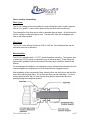
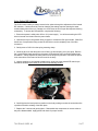
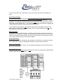
Color Light Streams
CLS-2
User Manual for 2010 CLS-2 | 12V RGB
6678 Owens Drive, Suite 105
Pleasanton, CA 94588
(888) 704-2276 toll-free
www.fiberstars.com
79-15216-02 REV. A1
1 of 7
Introduction
The CLS-2 by Fiberstars, an Energy Focus Company, in the most efficient RGB
LED Fiber illuminator available that will run maintenance free for years. It has a
low power consumption and a robust design that enables it to be installed in
places that are unsuitable for other types of illuminators.
IMPORTANT SAFETY INSTRUCTIONS!
1.
Save these instructions.
2. Read and follow all safety instructions carefully.
3. This product must be installed in accordance with the applicable
installation code by a person familiar with the construction and
operation of the product and hazards involved.
4. To be used with a listed Class II power supply only.
5. Inherently Protected.
6. Not for use in fire rated installations.
7. Suitable for Damp Locations.
8. Type IC Recessed
Consignes de sécurité importantes!
1.
Conservez ces instructions.
2. Lisez et suivez attentivemant toutes les consignes de sécurité.
3. Ce produit doit être installé en conformité avec le code d'installation
par une personne familière avec la construction et le fonctionnement
du produit et des risques impliqués.
4. Pour être utilisé avec une Classe II énumérés alimentation
seulement.
5. Intrinsèquement protégées
6. Ne pas utiliser pour les installations de feu.
7. Convient pour Damp Localisations.
8. Type IC Recessed.
79-15216-02 REV. A1
2 of 7
Installation:
The CLS-2 can be used for many applications including architectural and landscape,
structure illumination, pool/spa water feature illumination, etc.
The following considerations should be made for choosing a mounting location:
1. The CLS-2 is suitable for use in damp and dry locations. Do not submerge or
mount in a location that is exposed to a constant water stream.
2. The CLS-2 may be mounted in a horizontal or vertical position.
3. Use the stainless steel mounting bracket.
4. Do not mount the illuminator in an explosive environment or near combustible
materials.
5. Do not keep the CLS-2 in ambient air temperature in excess of 150°F (66°C).
Lower temperatures do not adversely affect the performance of the CLS-2.
6. Do not cover the fins or insulate the unit from air flow.
7. Do not encase the CLS-2 in concrete or bury in the earth.
8. Do not hang or use the power cord as a support for the CLS-2 as it is not a
pendant light.
Using Supplied Mounting Bracket:
1. The CLS-2 should be mounted using the supplied mounting bracket.
2. The mounting bracket can be mounted to wood, masonry, drywall, or metal by
using the appropriate fasteners.
3. Make sure the mounting surface is stable prior to installation of the CLS-2.
4. The bracket can be secured to the mounting surface prior to installing the CLS-2
5. Use a #10 screw appropriate to the attachment surface.
6. The fiber should be supported by a separate means appropriate to support the
fiber and for the attachment surface.
7. Do not try to support long length of fiber using only the CLS-2 as the main
support.
Electrical connections:
1. The CLS-2 must be connected to a Class II power supply. Use a power supply
that is appropriate to the installation. The power source is 12 VAC power. The
minimum output for the source should be 5W (volt amps) per CLS-2 unit. The
connection should be made in a junction box or at the power supply.
2. The lead wires are 18awg stranded and tinned copper.
3. For weatherproof connections, a Heyco fitting or equivalent can be used in the
junction box to seal the lead cable. The power cable is already sealed on the
CLS-2.
79-15216-02 REV. A1
3 of 7
Fiber Luminaire Compatibility
Fiber Types:
The CLS-2 is designed for side peripheral or end emitting fiber with a numeric aperture
(NA) of .5 or greater. Lower numeric aperture fiber will work with less efficiency.
The composition of the fiber can be solid or stranded, glass or plastic. At the focal point,
there is virtually no ultraviolet light or heat. The end of the fiber will not degrade over
time as with other systems.
Fiber Sizes:
The CLS-2 is most efficient for fiber of 0.38” to 0.50” dia. Small diameter fiber can be
used with some loss of efficiency.
Mounting Fiber:
The CLS-2 is equipped with a ¾” NPT, female threaded nose fitting. The common way
to attach the CLS-2 is using a compression type of electrical fitting. These fittings are
commercially available from several sources including Heyco, Kleinhuis, Sealcon and
Skintop.
For a weatherproof installation, use sealing tape on the threads before threading into the
nose and tighten the compression nut to the manufacturers suggested torque.
After installation of the compression fitting, insert the fiber into the fitting so that the fiber
end is flush with the focal plane. Do not force the fiber past the focal plane. For fibers
that are less than 0.56” dia (14.2mm) use an outer jacket to prevent the fiber from
passing through the nosepiece aperture.
79-15216-02 REV. A1
4 of 7
Color Option DIP Switches
The CLS-2 has the ability to change several color options through the adjustment of the internal
DIP switches. Caution should be used as changing the settings requires opening the water
resistant back plate of the unit. Damage can occur when the unit is open and exposed & during
reassembly. To access the DIP switches, complete the following:
1. Ensure that power is safely shut off from 12V power supply. You will be accessing the LED
driver’s internal circuit board near the power leads.
2. Unscrew the Heyco compression fitting to loosen or release the fiber optic bundle. Slide fiber
bundle out of compression fitting so that the LED driver can be completely free of the fiber
connection.
3. Gently remove CLS-2 from the spring mounting clamp.
4. Orient the driver so that the power cord is facing up and drooping over your hand. Remove
the 3 small Phillips head screws from the power cord back plate using a new #2 Phillips head
screwdriver. Gently separate the back plate from the body being careful to not strain the power
cord connections to the board or flex the board in the body.
5. Using a toothpick or mini-slotted screwdriver tip, gently move the desired DIP switch up to
activate the desired option listed on the chart in the following section.
6. Carefully place the back plate into position on the body making sure that the screw holes line
up without excessive twisting of the back plate.
7. Replace the 3 screws and gently tighten. Reassemble the components in reverse order as
they were disassembled. Apply power and check for proper function.
79-15216-02 REV. A1
5 of 7
The CLS-2 provides six (6) Fixed Colors, two (2) Color effects and three (3) selectable start
colors.
Color Synchronizing
The CLS-2 can color synchronize with all CLS-2* equipped Color Light Streams products and
PAL series Pool / Spa lights equipped with the LAL or LAU* LED lamps. For color
synchronization, all products should be connected to a single, appropriate type 12VAC magnetic
transformer. To color synch, simply turn off power for more than 1.5 seconds to ensure that all
units reset to factory default mode 1. Turn on power to re-energize the transformer supplying the
12VAC power to the products, they should now be synchronized.
* CLS-2 and PAL series lights w/ LAU lamps will need to have the DIP Switch settings in the
default position (all down/off) to color synchronize with PAL lights equipped with the LAL lamp
(PAL-2000 Color LED or PAL-Treo).
Mode Selection
To operate the unit, turn ON the power. To advance to the next color mode (1-8) just turn the
power OFF, then ON within 1.5 seconds until you select the required color mode. If you need to
reset for color synchronization purposes, just switch off the power for 2 seconds and the unit will
reset, ready to start from mode 1 when power is applied.
Color Hold Timing
The CLS-2 has the option to change it’s cycle timing from 2.5 seconds to 10 seconds for slower
color change cycle. Adjust this changing DIP switch #1 as shown by the chart below.
Start Color Selection
The choice of 3 Start Colors in mode 1 can be selected by adjusting the #2 or #3 DIP switch as
shown in the chart below.
Alternate Fixed Color
An alternate fixed color of Aqua instead of Red can be chosen for mode #5 only by adjusting DIP
switch #4 as shown in the chart below.
79-15216-02 REV. A1
6 of 7
Specifications
Mechanical
Weight: ………………………………………………………………8oz(198g)
Composition: ……………..………………… Aluminum Alloy and Polyamide
Regulatory Standards
ETL Tested to:
UL2108, CSA C22.2 #250.0 (Canadian) Listed component
Optical Specification
Numeric Aperture (NA): ………..…………………………………….. (.5)
Lumen Output (White)………………………….……………………..…73
White point
100% Green, ~50% red, ~ 50% Blue
Electrical Specification
Supply Voltage: ………………………………………………………..12V AC
Wattage (Volt amps): ……………………………………………………….5W
Thermal Specifications
Maximum Ambient Air Temperature: ………………………………150°F (66°C)
Minimum Ambient Air Temperature: ……..………………………..-40°F (-40°C)
79-15216-02 REV. A1
7 of 7