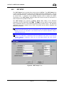
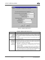
1
CalTool™ for RPTs A PC Based Calibration Utility For Reference Pressure Transducers in DH Instruments Products User’s Manual ©2001 DH Instruments, Inc. CalTool™ for RPTs User’s Manual High pressure liquids and gases are potentially hazardous. Energy stored in these liquids and gases can be released unexpectedly and with extreme force. High pressure systems should be assembled and operated only by personnel who have been instructed in proper safety practices. © 2001 DH Instruments, Inc. All rights reserved. Information in this document is subject to change without notice. No part of this document may be reproduced or transmitted in any form or by any means, electronic or mechanical, for any purpose, without the permission of DH Instruments, Inc. 4765 East Beautiful Lane Phoenix AZ 85044-5318 USA. DH Instruments makes sincere efforts to ensure the accuracy of its published materials; however, no warranty, expressed or implied, is provided. DH Instruments disclaims any responsibility or liability for any direct or indirect damages resulting from the use of the information in this manual or products described in it. Mention of any product does not constitute an endorsement by DH Instruments of that product. This manual was originally composed in English and was subsequently translated into other languages. In case of conflict between the English version and versions in other languages, the English version predominates. DH Instruments, DH, DHI, CalTool, COMPASS, molbox, PPC2, PPC2+, PPCK+ and RPM3 are trademarks, registered and otherwise, of DH Instruments, Inc. Windows is a registered trademark of Microsoft Corporation. Document No. 550125a 20011003 Printed in the USA. ©2001 DH Instruments, Inc. CalTool™ for RPTs User’s Manual TABLE OF CONTENTS TABLE OF CONTENTS ................................................................................ i TABLES ................................................................................................... iv FIGURES .................................................................................................. v ABOUT THIS MANUAL ............................................................................. vii 1. INTRODUCTION .................................................................................. 1 1.1 2. GETTING STARTED ............................................................................ 3 2.1 2.2 2.3 2.4 2.5 3. OVERVIEW ..............................................................................................................................................3 SYSTEM REQUIREMENTS .....................................................................................................................3 INSTALLING CALTOOL FOR RPTS .......................................................................................................3 RUNNING THE PROGRAM .....................................................................................................................4 UNINSTALLING .......................................................................................................................................4 OPERATING PRINCIPLES .................................................................... 5 3.1 4. PRODUCT OVERVIEW............................................................................................................................1 OVERVIEW ..............................................................................................................................................5 QUICK TIPS ....................................................................................... 7 4.1 4.2 HOW DO I? ..............................................................................................................................................7 APPLICATION EXAMPLES.....................................................................................................................9 4.2.1 4.2.2 4.2.3 4.2.4 5. CALIBRATING AN RPM3, PPC2+ OR PPCK+ REAL TIME WITH A PG7000 PISTON GAUGE AS THE REFERENCE ................................................................................................................................... 9 CALIBRATING AN RPM3 REAL TIME WITH A PPC2+ AS THE REFERENCE .......................................... 11 CALIBRATING AN RPM3, PPC2+ OR PPCK+ USING PREVIOUSLY ACQUIRED DATA (NOT RUNNING A TEST REAL TIME) ........................................................................................................ 12 CALIBRATING A PPC2 AF REAL TIME WITH A NON-DHI PISTON GAUGE ............................................ 13 MAIN PROGRAM ............................................................................... 15 5.1 5.2 5.3 5.4 OVERVIEW ............................................................................................................................................15 MAIN MENU BAR ..................................................................................................................................16 STATUS BAR.........................................................................................................................................17 MAIN TOOLBAR....................................................................................................................................18 5.4.1 5.4.2 5.5 RUN TOOLS ................................................................................................................................................ 18 DISPLAY TOOLS ........................................................................................................................................ 19 RUN WINDOWS.....................................................................................................................................20 5.5.1 5.5.2 5.5.3 5.5.4 5.5.5 5.5.6 DUT SETUP RUN WINDOW ....................................................................................................................... 20 TEST DEFINITION RUN WINDOW ............................................................................................................. 21 DATA GRID RUN WINDOW ........................................................................................................................ 21 DATA PLOT RUN WINDOW........................................................................................................................ 22 DUT/REFERENCE COMPARISON RUN WINDOW .................................................................................... 23 DUT AND REFERENCE OUTPUT RUN WINDOWS ................................................................................... 24 5.5.6.1 PG7000 RUN WINDOW .............................................................................................................. 25 5.5.6.2 PPC RUN WINDOW .................................................................................................................... 27 Page i ©2001 DH Instruments, Inc. CalTool™ for RPTs User’s Manual 6. [SETUP] MENU ................................................................................. 29 6.1 6.2 6.3 OVERVIEW ............................................................................................................................................29 [REFERENCE] .......................................................................................................................................29 [TEST] ....................................................................................................................................................33 6.3.1 6.3.2 6.3.3 6.3.4 6.4 [DUT]......................................................................................................................................................51 6.4.1 6.4.2 6.5 6.6 7. [REMOTE COMMUNICATIONS] ...........................................................................................................68 OVERVIEW ............................................................................................................................................69 INITIALIZATION.....................................................................................................................................69 7.2.1 7.2.2 7.3 AUTOMATED TEST INITIALIZATION ......................................................................................................... 70 MANUAL TEST INITIALIZATION................................................................................................................. 75 DATA ACQUISITION .............................................................................................................................77 7.3.1 7.4 MANUAL ENTRY DATA ACQUISITION....................................................................................................... 79 TEST CONCLUSION .............................................................................................................................79 [DATA] MENU ................................................................................... 83 8.1 8.2 8.3 8.4 OVERVIEW ............................................................................................................................................83 DATA FILE CREATION .........................................................................................................................83 NAMING AND STORING DATA FILES .................................................................................................83 DATA FILE STRUCTURE ......................................................................................................................84 8.4.1 8.5 DATA FILE FIELDS ..................................................................................................................................... 89 VIEWING A DATA FILE .........................................................................................................................91 8.5.1 8.5.2 9. [INITIALIZE TEST] TAB............................................................................................................................... 58 [RUN TEST] TAB......................................................................................................................................... 60 [RUN TEST DISPLAY] TAB......................................................................................................................... 62 [END TEST] TAB......................................................................................................................................... 64 [DATA FILE] TAB ........................................................................................................................................ 65 RUNNING A TEST ............................................................................. 69 7.1 7.2 8. DUT INTERFACE SETUP............................................................................................................................ 51 DUT SETUP................................................................................................................................................. 53 6.4.2.1 molbox DUT SETUP .................................................................................................................... 55 [IEEE-488 CARD]...................................................................................................................................57 [OPTIONS] .............................................................................................................................................58 6.6.1 6.6.2 6.6.3 6.6.4 6.6.5 6.7 CREATING TEST DEFINITIONS ................................................................................................................. 33 EDITING TEST DEFINITIONS ..................................................................................................................... 33 TEST DEFINITION SELECTOR................................................................................................................... 34 TEST DEFINITION EDITOR ........................................................................................................................ 34 6.3.4.1 TOOLBAR.................................................................................................................................... 35 6.3.4.2 [POINTS] TABLE ......................................................................................................................... 37 6.3.4.3 [POINTS] TAB ............................................................................................................................. 39 6.3.4.4 [SEQUENCE] TAB....................................................................................................................... 41 6.3.4.5 [REFERENCE] TAB..................................................................................................................... 42 6.3.4.6 [CONTROL] TAB ......................................................................................................................... 45 6.3.4.7 [LEAK TEST] TAB ....................................................................................................................... 47 6.3.4.8 [CYCLE] TAB............................................................................................................................... 49 PLOTTING TEST DATA............................................................................................................................... 92 VIEWING CALIBRATION COEFFICIENTS ................................................................................................. 93 DATA MANIPULATOR ........................................................................ 95 9.1 9.2 OVERVIEW ............................................................................................................................................95 MAIN MENU ...........................................................................................................................................97 9.2.1 9.2.2 9.2.3 9.3 [FILE]........................................................................................................................................................... 97 [CALIBRATION] .......................................................................................................................................... 99 [DUT] ..........................................................................................................................................................100 DATA MANIPULATOR DISPLAY ........................................................................................................100 ©2001 DH Instruments, Inc. Page ii CalToolä for RPTs User’s Manual 10. CALCULATIONS .............................................................................. 101 10.1 10.2 10.3 10.4 10.5 10.6 OVERVIEW ..........................................................................................................................................101 DETERMINING FACTORY PRESSURE..............................................................................................102 DETERMINING PA AND PM................................................................................................................104 ZNATERR, ZOFFSET MODIFICATIONS.............................................................................................105 PREDICTING “AS LEFT” DUT RESULTS ..........................................................................................106 MISCELLANEOUS...............................................................................................................................107 11. GLOSSARY ..................................................................................... 109 Page iii ©2001 DH Instruments, Inc. CalTool™ for RPTs User’s Manual TABLES Table 1. Table 2. Table 3. Table 4. Table 5. Table 6. Table 7. Table 8. Table 9. Table 10. Table 11. Table 12. Table 13. Table 14. Table 15. Table 16. Table 17. Table 18. Table 19. Table 20. Table 21. Table 22. Table 23. Table 24. Table 25. Table 26. Table 27. Table 28. Table 29. Table 30. Table 31. Table 32. Table 33. Table 34. Table 35. Table 36. Table 37. Table 38. Tools Available On The Run Toolbar....................................................................................... 18 Tools Available On The Display Toolbar ................................................................................. 19 <DUT/Reference Comparison> Run Window Fields............................................................. 24 <PG7000> Run Window Fields and Icons............................................................................... 26 <PPC> Run Window Fields ..................................................................................................... 28 <Setup Reference> Form Fields ............................................................................................ 31 <Test Definition Editor> Toolbar Features............................................................................ 36 <Test Definition Editor>, [Points] Table Features ............................................................... 38 <Test Definition Editor>, [Points] Tab Fields....................................................................... 40 <Test Definition Editor>, [Sequence] Tab Fields................................................................. 41 <Test Definition Editor>, [Reference] Tab Fields..................................................................... 43 <Test Definition Editor>, [Control] Tab Fields ..................................................................... 46 <Test Definition Editor>, [Leak Test] Tab Fields ................................................................. 48 <Test Definition Editor>, [Cycle] Tab Fields ........................................................................ 50 <DUT Interface Setup> Fields................................................................................................ 52 <DUT Setup> Form Fields ...................................................................................................... 54 <DUT Setup> for molbox1 and molbox RFM Form Fields...................................................... 56 <IEEE-488 Card Setup> Form Fields ..................................................................................... 58 <Options>, [Initialize Test] Tab Fields .................................................................................. 59 <Options>, [Run Test] Tab Fields ......................................................................................... 61 <Options>, [Run Test Display] Tab Fields ........................................................................... 63 <Options>, [End Test] Tab Fields ......................................................................................... 65 <Options>, [Data File] Tab Fields.......................................................................................... 66 <Manual Test Setup> Entry Form Fields ............................................................................... 76 <Test Complete> Screen Options .......................................................................................... 80 Data File Header Format ......................................................................................................... 85 Data File [Test Data] Section Fields ....................................................................................... 89 <Data Viewer> Toolbar ........................................................................................................... 92 <Data Manipulator>, [File] Menu Selections ......................................................................... 97 <Data Manipulator>, [Calibration] Menu Selections ............................................................ 99 Factory Pressure Equations .................................................................................................. 103 Definition of Factory Pressure Equation Terms..................................................................... 103 PA and PM Equations............................................................................................................ 104 Definition of PA and PM Equation Terms .............................................................................. 105 Changes to ZOFFSET and ZNATERR.................................................................................. 106 Predicted “As Left” DUT Results Equations .......................................................................... 107 Miscellaneous CalTool Equations.......................................................................................... 107 Miscellaneous Equation Terms ............................................................................................. 108 ©2001 DH Instruments, Inc. Page iv CalTool™ for RPTs User’s Manual FIGURES Figure 1. Figure 2. Figure 3. Figure 4. Figure 5. Figure 6. Figure 7. Figure 8. Figure 9. Figure 10. Figure 11. Figure 12. Figure 13. Figure 14. Figure 15. Figure 16. Figure 17. Figure 18. Figure 19. Figure 20. Figure 21. Figure 22. Figure 23. Figure 24. Figure 25. Figure 26. Figure 27. Figure 28. Figure 29. Figure 30. Figure 31. Figure 32. Figure 33. Figure 34. Figure 35. Main Program Menu ................................................................................................................ 16 Main Program Status Bar ........................................................................................................ 17 <DUT Setup> Run Window..................................................................................................... 20 <Test Definition> Run Window .............................................................................................. 21 <Data Grid> Run Window....................................................................................................... 22 <Data Plot> Run Window ....................................................................................................... 22 <DUT/Reference Comparison> Run Window ....................................................................... 23 <PG7000> Run Window.......................................................................................................... 25 <PPC> Run Window................................................................................................................ 27 <Setup Reference> Form....................................................................................................... 30 <Edit Reference> Form .......................................................................................................... 31 <Test Definition Selector> .................................................................................................... 34 <Test Definition Editor> Toolbar........................................................................................... 35 <Test Definition Editor>, [Points] Table............................................................................... 37 <Test Definition Editor>, [Points] Tab ................................................................................. 39 <Test Definition Editor>, [Sequence] Tab ........................................................................... 41 <Test Definition Editor>, [Reference] Tab ........................................................................... 43 <Test Definition Editor>, [Control] Tab................................................................................ 45 <Test Definition Editor>, [Leak Test] Tab............................................................................ 48 <Test Definition Editor>, [Cycle] Tab................................................................................... 50 <DUT Interface Setup> Form................................................................................................. 52 <DUT Setup> Form................................................................................................................. 53 <DUT Setup> Form for molbox1 and molbox ......................................................................... 56 <IEEE-488 Card Setup> Form................................................................................................ 57 <Options>, [Initialize Test] Tab............................................................................................. 59 <Options>, [Run Test] Tab.................................................................................................... 61 <Options>, [Run Test Display] Tab ...................................................................................... 63 <Options>, [End Test] Tab .................................................................................................... 64 <Options>, [Data File] Tab .................................................................................................... 66 <Remote Communications> Tool ......................................................................................... 68 <DUT Selection & I/O Setup> Form ...................................................................................... 71 Test Initialization <DUT Setup> Form ..................................................................................... 72 Test Initialization <Reference Setup > Form .......................................................................... 74 <User ID> Entry Form ............................................................................................................. 74 <Manual Test Setup> Entry Form .......................................................................................... 76 Page v ©2001 DH Instruments, Inc. CalTool™ for RPTs User’s Manual Figure 36. Figure 37. Figure 38. Figure 39. Figure 40. Figure 41. <Manual Pressure Entry> Form ............................................................................................ 79 <Test Complete> Screen ....................................................................................................... 80 <Data File Viewer> Form ....................................................................................................... 91 <%DUTSpan Error> Plot ........................................................................................................ 93 <View Calibration> Form ....................................................................................................... 94 <Data Manipulator> Form...................................................................................................... 96 ©2001 DH Instruments, Inc. Page vi CalTool™ for RPTs User’s Manual ABOUT THIS MANUAL Manual Conventions This manual provides the information necessary to set up and run CalTool for RPTs software. It also includes a great deal of additional information provided to help you optimize CalTool use and take full advantage of its many features and functions. Before using the manual, take a moment to familiarize yourself with the Table of Contents structure. Section 2 will help you get started, Section 4 provides quick tips and application examples. Section 10 documents the calculations used by CalTool. Other sections describe each of the main menu selections in detail. Certain words and expressions have specific meaning as they pertain to CalTool for RPTs and DH Instruments products. The Glossary (see Section 11) is useful as a quick reference for specific terms and expressions as they are used in this manual and the CalTool program. For those of you who don’t read manuals, go directly to Section 2 to install CalTool and then Section 3 for a summary of operating principles. Later … when you have questions or start to wonder about all the great features you might be missing, get into the manual. Cross references are used extensively to direct you towards additional information on a topic. Cross references are generally in parentheses and give the reference’s section number. For example: (see Section 11). Frequent reference is made to “the DUT’s Operation and Maintenance Manual, referring to the manual that is delivered with a DHI product. [ ] indicates CalTool controls such as menu and tab selections (for example [Setup]) or buttons and icons (for example [Abort Test] icon). Menu or tab selection paths are always described hierarchically from highest to lowest level. For example: [Tools], [Options], [Maintain Lists] tab). < > indicates CalTool text displays such as screen names, form names, field names, prompts, warnings and instructions (for example: <Enter user ID>) or CalTool functional modules (for example <Data Manipulator>. (CAUTION) is used in the manual to identify user warnings and cautions. (NOTE) is used in the manual to identify operating and applications advice and additional explanations. Page vii ©2001 DH Instruments, Inc. CalTool™ for RPTs User’s Manual NOTES ©2001 DH Instruments, Inc. Page viii CalTool™ for RPTs User’s Manual 1. I NTRODUCTION 1.1 PRODUCT OVERVIEW CalTool for RPTs is intended to provide assistance in the calibration of the reference pressure transducers (RPTs) in all supported DH Instruments products in which pressure transducers are used. CalTool supports automation of the calibration process to the extent supported by the hardware available. All the necessary tools required to set test pressures, gather data, calculate optimum calibration coefficients, evaluate calibration results, write new coefficients to the device under test and generate calibration reports are provided by CalTool. CalTool maximizes automation when using DH Instruments calibration references but operation with any reference is supported. CalTool is NOT intended to assist in using a DH Instruments calibration reference to calibrate nonDH Instruments devices. DHI’s COMPASS® series of calibration assistance software is offered to support using DHI references to calibrate non-DHI devices. Before using CalTool, read and thoroughly familiarize yourself with the Calibration and Maintenance Section of the Operation and Maintenance Manual of the device you are calibrating. Page 1 ©2001 DH Instruments, Inc. CalTool™ for RPTs User’s Manual NOTES ©2001 DH Instruments, Inc. Page 2 CalTool™ for RPTs User’s Manual 2. G ETTING S TARTED 2.1 OVERVIEW This section explains how to install CalTool for RPTs on your computer and the necessary system requirements. 2.2 SYSTEM REQUIREMENTS CalTool for RPTs is an application designed for Windows 32 bit operating systems. As of the release of this manual, these include Windows 95, 98, NT and 2000. Although any computer able to run one of these operating systems has the basic requirements needed to run CalTool, it is recommended that the system running CalTool have the following minimum configuration: · Windows 95, 98, or NT · 200 MHz, Pentium processor · 32 MB RAM · 10 MB free hard disk space 2.3 INSTALLING CALTOOL FOR RPT S CalTool for RPTs is available by internet download (www.dhinstruments.com) and it is included on the DH Instruments general accessories CD delivered with most DHI measurement products. To install by download from the internet, simply execute the self extracting file and follow the installation program prompts. Follow the instructions included with the general accessories CD to install CalTool from this media. To install CalTool from a stand alone CD: Insert the CalTool for RPTs CD into the CD drive. If the auto run feature is enabled on the computer, the setup application runs automatically. If the setup program does not run after 10 seconds, press the Windows [Start] button and select [Run]. In the Run dialog box, type d:\setup or f:\setup, depending on the drive letter of the CD drive of the installation disk. Select CalTool for RPTs from the list of applications and follow the installation prompts to install the program. OR Page 3 ©2001 DH Instruments, Inc. CalTool™ for RPTs User’s Manual Insert the CalTool for RPTs CD into the CD drive. Use the Add/Remove Programs feature in the Windows Control Panel. Press the Windows [Start] button and select [Settings] followed by [Control Panel]. Double-click the Windows [Add/Remove Programs] icon and click the [Install] button. Follow the prompts to install CalTool. 2.4 RUNNING THE PROGRAM When the software installation is complete, a new Windows group is created to hold the CalTool for RPTs program. To run the program, select it by pressing the Windows [Start] button, selecting the [Programs] sub-menu followed by the [CalTool for RPTs] group. Click the [CalTool for RPTs] icon to start the program. If a new program shortcut is created, make sure the <Start In> directory of the shortcut points to the installation directory of CalTool. All custom settings for CalTool are stored in this directory. To view the <Start In> directory of a shortcut: right click the shortcut and select [Properties], select the <Short Cut> folder on the display window. The <Start In> label is located in the middle of the display. 2.5 UNINSTALLING To uninstall CalTool, use the <Remove CalTool for RPTs> icon in the program group created during installation. As an alternative, use the Add/Remove Programs feature in the Windows Control Panel and select CalTool for RPTs. In both cases, a series of prompts must be followed in the application removal program to uninstall CalTool. All installation files and registry updates are removed. Data directories created by running CalTool are not removed by uninstalling. It is up to the user to manually remove these data directories. The application removal program always displays a message indicating CalTool was not completely removed when executed after new Data Files have been created. Any file management tool such as Windows Explorer can be used to remove these data directories. The Data Files are not affected by uninstall to avoid accidentally removing data. ©2001 DH Instruments, Inc. Page 4 CalTool™ for RPTs User’s Manual 3. O PERATING P RINCIPLES 3.1 OVERVIEW CalTool for RPTs is an application designed to provide assistance in calibrating the Reference Pressure Transducer(s) (RPTs) in DH Instruments products. CalTool is generally used by the calibration laboratory responsible for calibrating DHI products. Once CalTool has been installed on a suitable computer (see Section 2), the basic steps of running a calibration using CalTool are: Set up a pressure reference, the device that will apply reference pressures (see Section 6.2). This step can be performed once when first setting up CalTool. Create a Test Definition to define the test procedure (see Section 6.3). performed once for each type of device under test (DUT). This step can be Run a test and collect data (see Section 7). Use the Data Manipulator to evaluate the test data and possible adjustments to be made (see Section 9). Use the Data Manipulator to write new coefficients to the DUT if desired (see Section 9.2.2). Create a calibration report if desired (see Section 9.2.1). Using the automated data acquisition features of CalTool is recommended for general use. All selectable DUTs and DH Instruments references support RS232 communications and the majority of them come standard with an IEEE-488 interface. A computer equipped with one or more RS232 ports and/or a National Instruments (or CEC) IEEE-488 card can be used to calibrate up to 15 DUTs at a time. The same effort required to calibrate one DUT can successfully calibrate up to 15 when duplicate DUTs are available. When full automation is not supported by the hardware available, any combination of automated and manual operation is supported. The reference and any DUT can both be used manually. If all devices are manual or test data taken at another time is available, it may be preferable to use a fully manual entry test (see Section 7.2.2) to avoid the extra operator prompts associated with running a real-time test. Multiple DUTs can be calibrated at the same time using any combination of RS232, IEEE-488 and/or manual entry interfaces. Page 5 ©2001 DH Instruments, Inc. CalTool™ for RPTs User’s Manual Use [Run], [Run Test] or [Run], [Manual Entry Test] to run a test. Realize that many aspects of the test can be controlled and customized using the features found in [Setup], [Options] (see Section 6.6). Test initialization and execution, default screen display, Data File naming conventions, default interfaces settings and pressure unit are all customizable. All tests are separated into three steps: initialization, data acquisition and data manipulation. The data acquisition phase is the process of obtaining test data from all DUTs and the pressure reference. This data is later manipulated to obtain new calibration coefficients for each DUT. Data can be obtained by either running a test through the [Run], [Run Test] menu option, which steps through points in a test file or by entering each test point manually using the [Run], [Manual Entry Test] option (see Section 7.2.2). All test information is written to a delimited Data File that can be imported into other applications if desired. When the test is complete, a <Test Complete> screen displays to allow easy access to many common Data File operations (see Section 7.4). This is the most convenient way to access the <Data Manipulator>. When the <Data Manipulator> is closed, program control is returned to the <Test Complete> dialogue. Using the <Data Manipulator> from the <Test Complete> dialog at the end of the test allows the <Data Manipulator> to be used to act on multiple Data Files created by one test of multiple DUTs. Accessing the <Data Manipulator> from the [Data], [Manipulate Data] menu choice can only be used to manipulate one Data File at a time. In the data manipulation phase of a test, the <Data Manipulator> calculates calibration coefficients (PA and PM) for the DUTs based on the data collected in the data manipulation phase and displays the corresponding predicted “as left” data (see Section 10). The new calibration coefficients can be activated to any and all DUTs using this tool. A report, including a graph, can be created to document the calibration and a Results File can be saved to store the results of the calibration in a comma delimited file. The <Data Manipulator> can be used outside of the test process to view and/or manipulate data in older Data Files. In this case, use the [Data], [Manipulate Data] menu choice. ©2001 DH Instruments, Inc. Page 6 CalTool™ for RPTs User’s Manual 4. Q UICK T IPS 4.1 HOW DO I? Set up and run a calibration? Set up a pressure reference to define the device that will apply reference pressures (see Section 6.2). Create a Test Definition to define the test procedure (see Section 6.3). Run the test and acquire data (see Section 7). Use the <Data Manipulator> to view results including new calibration coefficients and predicted “as left” data (see Section 9). Write new calibration to the device under test and print report if desired (see Section 9). Repeat a test point or pause test execution? The main toolbar contains [Skip Back], [Skip Forward] and [Pause] icons (see Section 5.4.1). Use these icons to change the current test point or to pause the test as needed. Repeating test points after a new test pressure has been set can affect the hysteresis of the RPT. When possible, try to repeat test points before setting the next test pressure. Avoid having to go through undesired initialization steps each time a test is started? Use the [Setup], [Options], [Initialize Test] tab to set preferences to include or exclude the various test initialization steps (see Section 6.6.1). Abort a test that is running? Press the [Abort] key on the main toolbar (see Section 5.4.1) or use the corresponding [Toolbar] menu option. Check the DUT(s) information or determine what Test Definition is being used while a test is running? Click on the [View DUT] or [View Test] toolbar icons to cause the DUT or Test Definition screens for the current DUT or test to appear without affecting test execution. Close or move the display to view the previous run windows (see Section 5.4.2). Page 7 ©2001 DH Instruments, Inc. CalTool™ for RPTs User’s Manual Repeat the same test several times without having to pause or restart the test? Specify multiple test cycles in the Test Definition. In the [Sequence] tab of the Test Definition (see Section 6.3.4.4) specify a number greater than one under <Number of Test Cycles>. The complete pressure point sequence will run for the number of times specified without initializing between runs. Change the default RS232 port for reading DUTs so that I don’t have to re-select the port manually every time in the <DUT Setup> screen of test initialization? Use [Setup], [Options], [Run Test], <Default RS232 Port> to edit the default RS232 port (see Section 6.6.2). Add or remove a test point while editing a Test Definition? In the Test Definition [Points] Table, double click any test point to automatically remove it from the [Points] table. All subsequent test points are shifted up. To add a test point, press the [Insert] button and select <New Test Point> from the popup menu. Then drag the pencil icon to the point location to insert the new point. Alternatively, place the cursor in the desired field and press the computer’s [Insert] key to avoid the drag and drop operation. All test points will shift down leaving an opening to enter a new test point (see Section 6.3.4.2). Change the resolution with which the reference and/or DUT readings are displayed and recorded in the Data File? DUT resolution and reference resolution are determined by the <Pressure Display Resolution> selection on the Test Definition [Reference] tab (see Section 6.3.4.5). Set the pressure unit in which a test will be executed? The pressure unit of measure is set in the Test Definition [Sequence] tab (see Section 6.3.4.4). Troubleshoot communications with remote devices (references or DUTs)? Use [Setup], [Remote Communications] (see Section 6.6) to interface directly with the device, send command strings and display the responses. Changes to interface settings made in [Setup], [Remote Communications] are temporary. If changes were necessary to establish communications, these changes must be made in the device’s hardware setup. Import CalTool Data Files into Excel? From within Excel select [File], [Open], locate and select the CalTool Data File that you would like to import. Excel will open the Text Import Wizard. Select the “Delimited” option, and the [Next] button. Choose the “semicolon” delimiter or other selected delimiter (see Section 6.6.5) and complete the action by pressing the [Finish] button. Be careful that you do not overwrite your CalTool Data File with an Excel written file, as the overwritten file will no longer be compatible with the CalTool <Data Manipulator>. Change piston-cylinders in the piston gauge reference between points in a calibration? Insert a <Piston-cylinder change> into the Test Definition [Points] table (see Section 6.3.4.2). ©2001 DH Instruments, Inc. Page 8 CalTool™ for RPTs User’s Manual Include in a test a point that is the lowest point that can be set by the piston gauge? Insert a <Minimum Pressure Point> into the Test Definition [Points] table (see Section 6.3.4.2). Make a point in a test that is not a set pressure but just a vented condition? Insert a <Vent Point > into the Test Definition [Points] table (see Section 6.3.4.2). Restore a device under test to its original or another condition after having activated a calibration? If you are still in the <Data Manipulator> with the Data File that was activated loaded, use [Calibration], [Restore Calibration] (see Section 9.2.2). If not, use [Setup], [DUT] (see Section 6.4) or direct entry through the DUT front panel entry (see the DUT Operation and Maintenance Manual). 4.2 APPLICATION EXAMPLES 4.2.1 CALIBRATING AN RPM3, PPC2+ OR PPCK+ REAL TIME WITH A PG7000 PISTON GAUGE AS THE REFERENCE To calibrate an RPM3, PPC2+ or PPCK+ with a PG7000 piston gauge real time using CalTool, follow the steps below: Set up the PG7000 reference using [Setup], [Reference] (see Section 6.2). - Create a new reference. - Select DH Instruments from the <Manufacturer> dropdown list. - Select the appropriate PG7000 model from the <Model> dropdown list. - Select the interface your computer will use to communicate with the PG7000 from the <Interface> dropdown list. Use [Setup], [Test] to create a Test Definition defining the test procedure that CalTool will run to take “as received” calibration data from the reference and the DUT (see Section 6.3). - The normal points sequence is 0, 20, 40, 60, 80, 100 % FS ascending and descending. If running an absolute measurement mode test, edit the <Points> table replacing zero with the lowest pressure available from the PG7000. - On the Test Definition [Reference] tab, be sure to select the PG7000 you set up in Step . Page 9 ©2001 DH Instruments, Inc. CalTool™ for RPTs User’s Manual Run the test using [Run], [Run Test] or by pressing the [Run] toolbar icon (see Section 7.2.1). - In the <Select Test> window, select the Test Definition that was created in Step . - In the <DUT Selection & I/O Setup> window select the appropriate DUT type from the <DUT Type> dropdown list, enter an identification value in the <Identification> field if desired, select the interface type from the <Interface Type> dropdown list, click on the <Interface Settings> field to change the settings if necessary. Repeat for each DUT, one row per DUT, if testing more than one DUT at a time. - In the <DUT Setup> window enter or edit an <Identification> if desired, specify the <Calibration Range> from the dropdown list, edit the <Calibration Range FS> if necessary and click <Use AutoZ> to show an “x” if you want the “as received” data to be taken with the DUT AutoZ on. Repeat for each DUT in a multi-DUT test or press [Copy Settings] for all the DUTs to have the same range and AutoZ settings. - In the <Reference Setup> window, click on the <Mass Set>, <Mass Bell> and <Piston-Cylinder> that will be used to run the test. Note that the pressure range resulting from the selected elements is actively displayed in the <Nominal Pressure Range> field. - In the <User ID> window, identify the person running the test. - Follow the on screen prompts and instructions to run the test points (see Section 7.3). When the <Test Complete> screen is reached, select [Manipulate Data] (see Section 7.4). - Once in the <Data Manipulator> (see Section 9), observe the predicted “as left” data. - If the data is acceptable, use [Calibration], [Activate Calibration] to write the new calibration coefficients for the current range of the DUT (see Section 9.2.2). - Use [File], [Save Calibration Results] to create a Results File with all the test and “as received” and “as left” calibration information (see Section 9.2.1). - Use [File], [Generate Report From Data] to generate a calibration report if desired. Then use [File], [Save Report] and/or [Print Report] if desired. ©2001 DH Instruments, Inc. Page 10 CalTool™ for RPTs User’s Manual 4.2.2 CALIBRATING AN RPM3 REAL TIME WITH A PPC2+ AS THE REFERENCE To calibrate an RPM3, PPC2+ or PPCK+ with a PPC2+ as the reference real time using CalTool, follow the steps below: Set up the PPC2+ reference using [Setup], [Reference] (see Section 6.2). - Create a new reference. - Select DH Instruments from the <Manufacturer> dropdown list and PPC2+ from the <Model> dropdown list. - Select the interface your computer will use to communicate with the PPC2+ from the <Interface> dropdown list. Use [Setup], [Test] to create a Test Definition defining the test procedure that CalTool will run to take “as received” calibration data from the reference and the DUT (see Section 6.3). - The normal points sequence is 0, 20, 40, 60, 80, 100 % FS ascending and descending. If running an absolute measurement mode test, edit the <Points> table replacing zero with the lowest point the PPC2+ can set reliably. - On the Test Definition [Reference] tab, be sure to select the PPC2+ you set up in Step . - On the Test Definition [Control] tab, select <Reference> from the <Pressure Controller> dropdown list. Then select the desired control parameters (typically <Dynamic> for <Control Mode> and <0.005%> for <Hold Setting (%DUTSpan)>. Run the test using [Run], [Run Test] or by pressing the [Run] toolbar icon (see Section 7.2.1). - In the <Select Test> window, select the Test Definition that was created in Step . - In the <DUT Selection & I/O Setup> window select the appropriate DUT type from the <DUT Type> dropdown list, enter an identification value in the <Identification> field if desired, select the interface type from the <Interface Type> dropdown list, click on the <Interface Settings> field to change them if necessary. Repeat for each DUT, one row per DUT, if testing more than one DUT at a time. - In the <DUT Setup> window enter or edit an <Identification> if desired, specify the <Calibration Range> from the dropdown list, edit the <Calibration Range FS> if necessary and click <Use AutoZ> to show an “x” if you want the “as received” data to be taken with the DUT AutoZ on. Repeat for each DUT in a multi-DUT test or press [Copy Settings] for all the DUTs to have the same range and AutoZ settings. Page 11 ©2001 DH Instruments, Inc. CalTool™ for RPTs User’s Manual - In the <Reference Setup> window, click on the <Available Reference Range> that you want to use as the PPC2+ range to be active in the calibration. Note that CalTool shows its recommended range based upon the pressures in the Test Definition <Points> table and the available PPC2+ ranges. - In the <User ID> window, identify the person running the test. - Follow the on screen prompts and instructions to run the test points (see Section 7.3). When the <Test Complete> screen is reached, select [Manipulate Data] (see Section 7.4). - Once in the <Data Manipulator>, observe the predicted “as left” data. - If the data is acceptable, use [Calibration], [Activate Calibration] to write the new calibration coefficients for the current range of the DUT (see Section 9.2.2). - Use [File], [Save Calibration Results] to create a Results File with all the “as received” and “as left” calibration information (see Section 9.2.1). - Use [File], [Generate Report From Data] to generate a calibration report if desired. Then use [File], [Save Report] and/or [Print Report] if desired (see Section 9.2.1). 4.2.3 CALIBRATING AN RPM3, PPC2+ OR PPCK+ USING PREVIOUSLY ACQUIRED DATA (NOT RUNNING A TEST REAL TIME) To create a Data File that can be used by the CalTool <Data Manipulator> to calculate new calibration coefficients and predicted “as left data”, follow the steps below. This procedure is useful if you would like to use CalTool to process data that was taken on another system or at another time, whether or not the reference and DUT(s) used are available to connect remotely. Set up the reference piston gauge using [Setup], [Reference] (see Section 6.2). - Create a new reference. Run the test using [Run], [Manual Entry Test] (see Section 7.2.2). - Fill out the <Manual Test Setup> form. - In the <DUT Selection & I/O Setup> window select the appropriate DUT type from the <DUT Type> dropdown list, enter an identification value in the <Identification> field if desired, select the interface type from the <Interface Type> dropdown list, click on the <Interface Settings> field to change them if necessary. Repeat for each DUT, one row per DUT, if testing more than one DUT at a time. If remote communications with the DUT are not active, select <Manual>. ©2001 DH Instruments, Inc. Page 12 CalTool™ for RPTs User’s Manual - In the <DUT Setup> window enter or edit an <Identification> if desired, specify the <Calibration Range> from the dropdown list, edit the <Calibration Range FS> if necessary and click <Use AutoZ> to show an “x” if you want the “as received” data to be taken with the DUT AutoZ ON. Repeat for each DUT in a multi-DUT test or press [Copy Settings] for all the DUTs to have the same range and AutoZ settings. If the DUT data was taken with AutoZ ON, be sure to check the <AutoZ ON> box and enter the value of <ZOFFSET> if remote communication with the DUT does not supply it. - If remote communication with the reference is not setup in the <Reference Setup> (see Section 6.2), edit the <Pressure Range>, <Piston-Cylinder SN>, <Mass Bell SN>, <Mass Set SN> and <Piston-Cylinder KN> to describe the piston gauge. These fields are simple labels that will be logged into the test Data File, they do not affect operation. If remote communications with the reference are set up, in the <Reference Setup> window select the appropriate piston-cylinder, mass loading bell and mass set. - In the <User ID> window, identify the person running the test. - Follow the on screen prompts and instructions to run the test points (see Section 7.3.1). When the <Test Complete> screen is reached, select [Manipulate Data] (see Section 7.4). - Once in the <Data Manipulator> (see Section 9), observe the predicted “as left” data. - If the data is acceptable, use [Calibration], [Activate Calibration] to write the new calibration coefficients for the current range of the DUT (see Section 9.2). - Use [File], [Save Calibration Results] to create a Results File with all the “as received” and “as left” calibration information (see Section 9.2.1). - Use [File], [Generate Report From Data] to generate a calibration report if desired. Then use [File], [Save Report] and/or [Print Report] if desired (see Section 9.2.1). 4.2.4 CALIBRATING A PPC2 AF REAL TIME WITH A NON-DHI PISTON GAUGE To calibrate a PPC2 AF with a non-DHI piston gauge real time with CalTool assistance, follow the steps below: Set up the reference piston gauge using [Setup], [Reference] (see Section 6.2). - Create a new reference. - Select <Other> from the <Manufacturer> dropdown list. Use [Setup], [Test] to create a Test Definition defining the test that CalTool will run to take “as received” calibration data from the reference and the DUT (see Section 6.3). - The normal points sequence is 0, 20, 40, 60, 80, 100 % FS ascending and descending. Page 13 ©2001 DH Instruments, Inc. CalTool™ for RPTs User’s Manual - On the Test Definition [Reference] tab, be sure to select the non-DHI reference you set up in Step . - On the [Control] tab select <Manual> from the <Pressure Controller> dropdown list. Run the test using [Run], [Run Test] or by pressing the [Run] toolbar icon (see Section 7.2.1). - In the <Select Test> window, select the Test Definition that was created in Step . - In the <DUT Selection & I/O Setup> window select the appropriate DUT type from the <DUT Type> dropdown list, enter an identification value in the <Identification> field if desired, select the interface type from the <Interface Type> dropdown list, click on the <Interface Settings> field to change them if necessary. Repeat for each DUT, one row per DUT, if testing more than one DUT at a time. - In the <DUT Setup> window enter or edit an <Identification> if desired, specify the <Calibration Range> from the dropdown list, edit the <Calibration Range FS> if necessary and click <Use AutoZ> to show an “x” if you want the “as received” data to be taken with the DUT AutoZON. Repeat for each DUT in a multi-DUT test or press [Copy Settings] for all the DUTs to have the same range and AutoZ settings. - In the <Reference Setup> window, edit the <Pressure Range>, <Piston-Cylinder SN>, <Mass Bell SN>, <Mass Set SN> and <Piston-Cylinder KN> to describe the non-DHI piston gauge. These fields are simple labels that will be logged into the test Data File, they do not affect operation. - In the <User ID> window, identify the person running the test. - Follow the on screen prompts and instructions to run the test points (see Section 7.3). When the <Test Complete> screen is reached, select [Manipulate Data] (see Section 7.4). Once in the <Data Manipulator> (see Section 9), observe the predicted “as left” data. - If the data is acceptable, use [Calibration], [Activate Calibration] to write the new calibration coefficients for the current range of the PPC2 AF (see Section 9.2.2). - Follow the on-screen prompts and run the PPC2 AF ZNATERR routine from the PPC2 AF front panel as requested (see the PPC2 AF Operation and Maintenance Manual). - Use [File], [Save Calibration Results] to create a Results File with all the “as received” and “as left” calibration information (see Section 9.2.1). - Use [File], [Generate Report From Data] to generate a calibration report if desired. Then use [File], [Save Report] and/or [Print Report] if desired (see Section 9.2.1). ©2001 DH Instruments, Inc. Page 14 CalTool™ for RPTs User’s Manual 5. M AIN P ROGRAM 5.1 OVERVIEW The main program contains all of the necessary display information and menu options to set up and calibrate all ranges of any supported DUT. When CalTool is first started, the main screen displays without any child windows. Only after a menu option is selected does the screen update to display the corresponding window. The following features are directly available in the main program. · Main menu bar to access all CalTool menus and toolbar functions (see Section 5.2). · Status bar at the bottom of the screen that contains information on the current point in a test and the status of an operation (see Section 5.3). · Main Toolbar to access common test functions while a test is running (see Section 5.4). · Several individual run windows that are available when running a test to provide real time data acquisition information on the corresponding device (see Section 5.5). Page 15 ©2001 DH Instruments, Inc. CalTool™ for RPTs User’s Manual Figure 1. Main Program Menu 5.2 MAIN MENU BAR The main menu bar is divided into five separate selections. Each menu item is summarized below and covered in detail in various sections of this manual. · [Run] (see Section 7): Use this choice to launch test execution. Use [Run Test] for a test that will be run real time using a Test Definition and [Manual Entry Test] to enter test data manually outside the confines of a Test Definition. · [Setup] (see Section 6): All of the program set up features are contained in this menu choice. The ability to create references, Test Definitions, set up the supported IEEE-488 cards, set run test preferences and test communications are the available choices. · [Data] (see Section 8): Access tools to plot, view and manipulate test Data Files. · [Toolbar] (see Section 5.4.1): Each menu item is simply a menu representation of the corresponding run test toolbar icon. · [Window] (see Section 5.5): Choose which child window to display when a run mode has been selected. The windows can be tiled or cascaded if desired. ©2001 DH Instruments, Inc. Page 16 CalTool™ for RPTs User’s Manual 5.3 STATUS BAR The Status Bar is located at the bottom of the main screen (see Figure 1, Figure 2). In all run modes, CalTool flashes information related to the current operation on the Status Bar display. While running tests, two panels and a progress indicator also display with status information on the current test step and point. The blue panel on the left displays the current test step or function. Each point in a test sequence has five basic test steps: Pre Test Options (if specified in the Test Definition) occurs once at the beginning of a test. · Cycle Pressure · Leak Test Set Pressure to pressure point specified in the Test Definition. Ready check/stability Test for pressure at the set point. Dwell for dwell time at the set point after a Ready condition has been achieved. Take Data for length of averaging time after the dwell time has been completed. The red panel displays the current test point during a test. The notation used is “current cycle. current point <of> total cycles. total points per cycle”. For example, if a 2 cycle, 10 point test is executed, st point 3 of the 1 cycle displays as “1.3 of 2.10”. Refer to these displays to determine the new current point, when the [Skip Back] and [Skip Forward] icons are used. The Progress Indicator of the Status Bar is a horizontal bar across the bottom of the screen just above the other status indicators. It provides a visual indication of the relationship between the current test point and the number of points in a test. The left side of the progress bar represents 0 % progress and the right side represents 100 %. Each step and reading of a test point increments the progress indicator. When <Skip Back> and <Skip Forward> icons are used, the progress indicator continues to reflect the current test position. Figure 2. Main Program Status Bar Page 17 ©2001 DH Instruments, Inc. CalTool™ for RPTs User’s Manual 5.4 MAIN TOOLBAR Most features on this Toolbar (see Figure 1) are active only after one of the [Run] menu choices is selected. Depending on the type of run mode, some of the Toolbar options may be disabled. To use a tool, click on the tool icon. Use the [Toolbar] menu to access the toolbar functions without a mouse. Many Toolbar functions contain shortcuts that can be accessed quickly from a keyboard. 5.4.1 RUN TOOLS The Run Tools are used to alter the course of a running test. Table 1 describes the toolbar features not related to run screens. Table 1. Tools Available On The Run Toolbar ICON DESCRIPTION [Run Test] This function is identical to the [Run], [Run Test] menu selection (see Section 7.2.1). This is the only enabled Toolbar option when CalTool is in an idle state. (toolbar icon) [Step Back] Causes the current test point to be interrupted and the test point sequence to step back to the most recent set pressure step. Subsequent clicks within 1.5 second cause the test to step back one point for each click. This tool is used to repeat points when needed. (toolbar icon) [Step Forward] (toolbar icon) [Pause] (toolbar icon) [Abort] Causes the current test point to be interrupted and the test point sequence to step forward to the next step in a point sequence. To ensure that data is logged at each point, step forward can only be used up to the data acquisition step of the highest point executed. Most often, this tool is used to skip over previously executed points when the step back key has been used to go back several points. Suspends remote communications with all instruments being used by CalTool and pauses any test timers (e.g. dwell time). Use this feature to pause operation, for example to delay the start of readings at a point or to allow front panel access to an instrument after a test has started. To resume operation, click the [Pause] icon again. [Abort] causes the <Abort Test> confirmation pop-up to appear to abort the test that is running. When a test is aborted, a prompt as to whether to save the partial Data File created for that test may appear depending on the [Setup], [Options], [Initialize Test] tab choice. (toolbar icon) ©2001 DH Instruments, Inc. Page 18 CalTool™ for RPTs User’s Manual 5.4.2 DISPLAY TOOLS Table 2 describes Toolbar features that relate to CalTool run screens. Each of the Toolbar icons forces the corresponding display screen to the top of the display. Table 2. Tools Available On The Display Toolbar ICON [View DUT] DESCRIPTION Causes the <DUT Setup> window to display in the main screen with the information corresponding to all active DUTs. No editing or new DUT selections can be made at this time. (toolbar icon) [View Test] Causes the <Test Definition> window to display in the main screen with the information corresponding to the active Test Definition (see Section 6.3). This allows complete information on the current test procedure to be reviewed without interrupting a running test. (toolbar icon) [Data Grid] Display the <Data Grid> run window with the data logged for the current test. Use the list box at the top of the grid display to view data logged for other DUTs being run in the same test (see Sections 5.5.3, 8.4.1). (toolbar icon) [Data Plot] Display the <Plot> run window loaded with data from the current test. Use the list box at the top of the grid to view %FS Error plots of other DUTs being run in the same test. A combined plot of all %FS Error plots is also available in the list (see Section 5.5.4). The plots update real time as the test runs. (toolbar icon) [DUT/Reference Comparison] Display the <DUT/Reference Comparison> run window. This display provides convenient, real time pressure and error information for the reference and all active DUTs (see Section 5.5.5). (toolbar icon) [View Device Output] Displays a pop-up menu allowing the selection of the run window for all remotely enabled devices. Each run window contains setup and output information specific to the selected device (see Section 5.5.6). (toolbar icon) Page 19 ©2001 DH Instruments, Inc. CalTool™ for RPTs User’s Manual 5.5 RUN WINDOWS Run windows are used extensively by CalTool to display the current output and history of a test in progress. The Main Toolbar icons must be used to access these windows when a test is in progress. To scale a run window, click and drag the border to the desired size. Closing, minimizing or maximizing any of the run windows has no effect on test execution. A running test will continue to run even when all run windows are closed. The [Window] menu includes cascade and tile options for common default displays. The combination of these features makes the CalTool user interface totally customizable. The default run window display can be modified using the [Setup], [Options], [Run Test Display] tab selections (see Section 6.6.3). Use the [Toolbar] menu and the Main Toolbar to display run windows during a test (see Section 5.4). 5.5.1 DUT SETUP RUN WINDOW The <DUT Setup> run window displays the calibration and setup information for the active calibration range of all DUTs being run in the test. The display is identical to the <DUT Setup> window displayed during test initialization (see Section 7.2.1 and Figure 32), with the exception that the only available action is the ability to view other DUTs for multiple DUT tests. Click the serial number labeled tab of the desired DUT. Calibration data for other ranges cannot be viewed when a test is in progress. See Table 16 for information on all fields in this display. The <DUT Setup> run window cannot be scaled and the display should not be left open indefinitely during a test. Test data cannot be logged while the window is open. View the necessary information, then close the window. Figure 3. <DUT Setup> Run Window ©2001 DH Instruments, Inc. Page 20 CalTool™ for RPTs User’s Manual 5.5.2 TEST DEFINITION RUN WINDOW The <Test Definition> run window displays the active Test Definition during a test when the appropriate toolbar icon is pressed (see Section 6.3). No modifications to the active test can be made, nor can a test other than the one being run be viewed. The <Test Definition> run window cannot be scaled and the display should not be left open indefinitely during a test. Test data cannot be logged while the window is open. View the necessary information, then close the window. Figure 4. <Test Definition> Run Window 5.5.3 DATA GRID RUN WINDOW While running tests, the <Data Grid> run window is available to display the list of points and their associated data for all active DUTs. Every pressure point up to the current point in the current test cycle is displayed in this grid. The unit of measure for many columns is specified in the corresponding column header. As with the other run windows, the grid display is scalable. However, the individual grid columns do not automatically scale as the borders of the grid display are scaled. Instead click and hold the separator border between columns or rows and adjust the scale as desired. The dropdown listbox at the top of the display should be used to display test data for other DUTs included in a multiple DUT test. As a test progresses, the current point is automatically highlighted and selected in the grid. Use the selections on the [Setup], [Options], [Run Test Display] tab to prevent the automatic selection of the current test point if desired (see Section 6.6.3). When automatic grid line selection is ON, if the grid is scrolled to the top to view points taken earlier in the test, completion of a new point will force the grid display back to the last point. Page 21 ©2001 DH Instruments, Inc. CalTool™ for RPTs User’s Manual The data columns and ordering of the columns in the grid is fixed. Realize that the grid does not display all of the data stored in the Data File, nor does it display the data in the same order. See Section 8.4 for details on how the Data File is formatted and information on the columns of data displayed on the <Data Grid> run window. When testing a molbox1 or molbox RFM with the <Upstream/downstream> selection, there are two <Grid Display Mode> selections, one for each RPT, even though there is only one DUT. Figure 5. <Data Grid> Run Window 5.5.4 DATA PLOT RUN WINDOW When running a test, the <Data Plot> run window can be used to display a real time %DUTSpan error plot for any and all DUTs. Use the dropdown menu at the top of the display to view data from a different DUT when running multiple DUTs. Figure 6. <Data Plot> Run Window ©2001 DH Instruments, Inc. Page 22 CalTool™ for RPTs User’s Manual 5.5.5 DUT/REFERENCE COMPARISON RUN WINDOW The <DUT/Reference Comparison> run window contains a simple display of errors useful when comparing the DUT and reference. The <DUT/Reference Comparison> run window is considered to be the CalTool main run screen. Information on each of the <DUT/Reference Comparison> run window fields is provided in Table 3. Figure 7. <DUT/Reference Comparison> Run Window Page 23 ©2001 DH Instruments, Inc. CalTool™ for RPTs User’s Manual Table 3. <DUT/Reference Comparison> Run Window Fields LABEL DESCRIPTION Red or Green Circular Indicator The pressure reference Ready/Not Ready indicator. The circle is green when the pressure is set and stable within the defined Ready criterion and red when Not Ready. Red or Green Square Indicator DUT in or out of tolerance indication. The square is green only when the instantaneous pressure error is within the tolerance specified in the Test Definition, [Sequence] tab (see Section 6.3.4.4). <Reference> Instantaneous reference pressure in the specified test pressure unit. If the reference is a PG7000 (Piston Gauge), no pressure value is displayed unless the PG7000 is in Ready condition. When the PG7000 is Not Ready or in manual entry, < ------- > displays in the field. <DUT(s)> The instantaneous DUT pressure labeled by the model of the DUT followed by the DUT’s serial number. The display is repeated for all active DUTs. The DUT pressure always displays in the pressure unit specified in the Test Definition [Sequence] tab (see Section 6.3.4.4). <Error (%DUTSpan)> DUT percent of span error for each DUT. The error is updated with each new DUT output. Percent of span error is calculated following ((DUTReference)/DUT span)*100 (see Section 10.6). 5.5.6 DUT AND REFERENCE OUTPUT RUN WINDOWS Each reference or DUT that can be read remotely has an associated output run window. Use the [View Device Output] toolbar function to view the desired output run window. These displays are device specific to show relevant settings and real time information specific to one device at a time. In some cases, the device settings can be changed by using tools on the associated output window. See Section 5.5.6 sub-sections for information on CalTool DUT and reference output run windows. Refer to the instruments Operation and Maintenance Manual for complete information on all its functions and displays. All output run windows display the model and serial number of the corresponding instrument in the window caption. Use this information to distinguish multiple windows of the same type instrument. Always use the tools on the run screen instead of the instrument front panel when running tests. Front panel access can interfere with remote communications and interfere with CalTool program execution. Use the run tools to change pressure and other test parameters as necessary when running a test. If you must use the instrument front panel while a test is running, use the [Pause] tool to suspend test execution and remote communications (see Section 5.4.1), allowing access to the front panel controls. ©2001 DH Instruments, Inc. Page 24 CalTool™ for RPTs User’s Manual 5.5.6.1 PG7000 RUN WINDOW The <PG7000> run window is used for all remotely enabled DH Instruments PG7000 piston gauges. Based on the model and embedded software version of the PG7000, some features may be disabled or not included on the run window. All relevant piston-cylinder, mass, pressure and ambient conditions information displays real time in the run window. Information on each of the <PG7000> run fields is listed in Table 4. The <PG7000> run window also includes a mini-toolbar allowing direct control of certain PG7000 functions (see the bottom of Table 4). Refer to the PG7000 Operation and Maintenance manual for complete information on PG7000 set up, functions and displays. Figure 8. <PG7000> Run Window Page 25 ©2001 DH Instruments, Inc. CalTool™ for RPTs User’s Manual Table 4. <PG7000> Run Window Fields and Icons LABEL/ICON DESCRIPTION Circular Indicator Green when the PG7000 pressure is Ready and red when the pressure is Not Ready. Refer to the PG7000 Operation and Maintenance for details on PG7000 Ready/Not Ready conditions. <Piston Position> The piston position relative to mid-stroke [mm]. <Fall Rate> <Rotation Rate> <Rotation Decay> The rate at which the piston is moving vertically (fall rate) [mm/min]. Piston rotation rate [rpm]. Rate at which piston rotation is decelerating [rpm/min]. <Piston Temperature> The temperature measured by the piston-cylinder platinum resistance thermometer [ºC]. <Pressure> The fully compensated PG7000 defined pressure in the unit of measure specified by the Test Definition. This value only displays when the PG7000’s Ready criteria are satisfied. <Target Pressure> The nominal pressure the PG7000 is setting. This value can be entered when [Automatic Pressure Generation] is active. <Nominal Mass Load> <True Mass Load> <Vacuum Pressure> <Temperature> The nominal mass load required to achieve the <Pressure> value [kg]. The total true mass loaded to achieve the <Pressure> value [kg]. The output of the PG7601 or PG7607 vacuum reference sensor [Pa]. The ambient temperature measured by the PG7000 [ºC]. <Ambient Pressure> The ambient pressure measured by the PG7000 [kPa]. <Humidity> The relative humidity measured by the PG7000 [%RH]. [Automatic Pressure Generation] Toggles the use of the automatic pressure generation function of the PG7000 when available. When turned ON, the piston position dead band value must be entered. Target pressures can then be set directly by entering the requested pressure into the <Target Pressure> field. The <Nominal Mass Load> value will display the required nominal mass to achieve the requested pressure. Automatic pressure generation capability must be set up on the PG7000 prior to running CalTool. If the function is not set up, no action occurs when this function is selected. [Toggle Auto Rotate] Toggles the state of the optional PG7000 auto rotate feature. When turned on, the PG7000 auto rotate function operates to rotate the piston at the appropriate time. The displayed icon always represents what will occur if the icon is clicked. Auto rotate should be turned OFF when the mass loading bell is not loaded. If the PG7000 does not have the motorized rotation option, this icon has no effect. ©2001 DH Instruments, Inc. Page 26 CalTool™ for RPTs User’s Manual Table 4. <PG7000> Run Window Fields and Icons (Continued) LABEL/ICON DESCRIPTION [Rotate] Equivalent to the PG7000 terminals momentary piston rotation key. Engages motorized rotation when pressed, release when not pressed. This icon has no effect if the PG7000 is not equipped with the motorized rotation option. [Change Mass Loading Resolution] This function is the equivalent of the [RES] key on the PG7000 Terminal. Use the dropdown menu next to the icon to select the desired mass loading resolution. Then press the icon to set the new resolution value. The mass load for the next requested target pressure will be specified with the selected resolution. Typical mass loading resolution used when calibrating DH Instruments RPTs is 0.1 kg (100 g). 5.5.6.2 PPC RUN WINDOW The <PPC> run window can be used not only to view the output of a specific DH Instruments PPC Pressure Controller/Calibrator model but also to control the test pressure directly. The windows toolbar icons are designed to act as a software interface to the front panel of the PPC. Use the toolbar icons in the same way the PPC front panel buttons are used. Features are also provided to control the test parameters and change the test target pressure (see Table 5). Hold down the up or down arrow icons by holding down the right mouse key to continuously increase or decrease the pressure. Release the icon to stop the pressure change. Figure 9. <PPC> Run Window Page 27 ©2001 DH Instruments, Inc. CalTool™ for RPTs User’s Manual Table 5. <PPC> Run Window Fields LABEL/ICON Circular Indicator <Rate> DESCRIPTION Green when the PPC pressure is Ready and red when the pressure is Not Ready. Refer to the PPCx operation and maintenance manual for complete information on PPC Ready/Not Ready conditions The current pressure rate of change [pressure unit/s]. <Pressure> Instantaneous PPCx pressure [Test Definition specified pressure unit]. <ATM> Atmospheric pressure output by the PPC’s on-board barometer [kPa]. <Range> The active PPC range. <Target Pressure> The last set target pressure. Enter a new target pressure and press the computer’s [Enter] key to set a new pressure with the PPCx. <Hold Limit> The active PPC hold limit. Enter a new value and press the computer’s [Enter] key to change the hold limit. <Stability Setting> The active PPC stability setting. Enter a new value and press the computer’s [Enter] key to change the stability setting. <Target Limit> The active PPC target limit. Only PPC2 and PPCK pressure controllers support this feature. Enter a new value and press the computer’s [Enter] key to change the target limit. [Toggle Vent] Toggles the state of the PPC vent function. [Increase Pressure] Increases pressure at the fast or slow up rate based on the <Fast/Slow> icon. Pressure increases as long as the icon is held down. [Decrease Pressure] Decreases pressure at the fast or slow down rate based on the <Fast/Slow> icon. Pressure decreases as long as the icon is held down. [Toggle Fast/Slow] Changes pressure increase/decrease rate from fast to slow to determine which PPC control rate will be used to change pressure when the [Increase Pressure] and [Decrease Pressure] icons are pressed. No pressure change occurs when this option is selected. [Abort Control] ©2001 DH Instruments, Inc. Aborts pressure control if the PPC is actively controlling. Page 28 CalTool™ for RPTs User’s Manual 6. [S ETUP ] M ENU 6.1 OVERVIEW The [Setup] menu contains all of the features required to set up CalTool to run tests and to troubleshoot communications. Once all required and/or desired features have been set up, future use of the setup options is necessary only to edit the existing setup. If CalTool is properly set up, tests can be run directly at any time by using the [Run], [Run Test] menu option. The [Setup] menu contains the following choices: · [Reference] (see Section 6.2): Used to set up the pressure references that will be used as standards when tests are run. · [Test] (see Section 6.3): Runs the <Test Definition Editor> to create, view, edit, and delete Test Definitions. · [DUT] (see Section 6.4): Displays the <DUT Setup> display loaded with the information of a single DUT with which remote communications are established. Allows editing of DUT information. · [IEEE-488 Card] (see Section 6.5): Allows the selection and set up of the IEEE-488 card in the computer running CalTool that CalTool will use for IEEE-488 communications. · [Options] (see Section 6.6): Many aspects of running tests with CalTool and CalTool Data Files can be customized using the features contained within in this menu. · [Remote Communications] (see Section 6.7): This is a troubleshooting tool used to test the remote interface of a and communications setup with a device. 6.2 [REFERENCE] [Setup], [Reference] is used to set up the pressure references that CalTool uses when running tests. All references set up, are available for selection in the <Test Definition Editor>, [Reference] tab which determines what reference is used when a test is run (see Section 6.3.4.5). It is therefore a good idea to set up all possible pressure references at one time so that they are available for selection from the dropdown menu when creating and editing Test Definitions. If a reference is deleted, Test Definitions that specify the deleted reference will return errors during test initialization. To select a Reference Definition to view, single click on the reference <Record Label> in the <List> display panel. To edit an existing Reference Definition, double click on the reference device listing or click on the [Edit] toolbar function with the desired Reference Definition highlighted. Double clicking the reference listing, clicking on the [Edit] toolbar icon or clicking the [New] toolbar icon causes the <Edit Reference Device> or <Add New Reference Device> pop-up to appear. These pop-ups are identical but differentiated by name to make it clear which task is currently being performed. Page 29 ©2001 DH Instruments, Inc. CalTool™ for RPTs User’s Manual The <Edit Reference Device> or <Add New Reference Device> pop-ups allow a pressure Reference Definition to be set up from scratch or edited from an existing one. If the reference is a DH Instruments product, remote communications with the reference are supported by CalTool, and remote interface settings can be specified. Non-DHI references are supported by manual data entry only. The purpose of the Reference Definition fields and settings as well as instructions on how to use them are provided in Table 6. When creating a new Reference Definition, all of the fields come up blank. When editing an existing Reference Definition, the fields come up populated with the information on that reference. When editing is complete, click <OK> to save changes. Do not use the following characters in any text entry field: \,/, :, *, ?, “, <,>, |, a comma or tab character. These characters will cause problems when importing the Data File. Figure 10. <Setup Reference> Form ©2001 DH Instruments, Inc. Page 30 CalTool™ for RPTs User’s Manual Figure 11. <Edit Reference> Form Table 6. <Setup Reference> Form Fields FIELD/BUTTON <Record Label> (required text entry field) <Manufacturer > (required dropdown selection list) <Model> (dropdown selection list) DESCRIPTION This field is analogous to a file name. The text entered should be a convenient label that makes the reference easily distinguishable from other references. Up to 40 characters can be used in the field. Defines the manufacturer of the reference device. If DH Instruments is selected, the <Model> list box is populated with all supported references. An <Other> choice is also available. Use <Other> to set up reference devices other than DHI models. When <Other> is selected, a pop-up appears for entry of the manufacturer name of the reference device. A remote interface with CalTool is not supported for non-DHI pressure references. Defines the model of the reference device. When the manufacturer is DH Instruments, the dropdown list choices include all supported DHI pressure reference models. All DHI models that have remote interfaces are supported by CalTool remote communications. CalTool cannot communicate with non-DHI references. Page 31 ©2001 DH Instruments, Inc. CalTool™ for RPTs User’s Manual Table 6. <Setup Reference> Form Fields (Continued) FIELD/BUTTON <Serial Number> (required text entry field) <Identification> (optional text entry field) <Calibration Date> (optional text entry field) <Remote Interface> (dropdown selection list) DESCRIPTION Write in the reference device’s serial number. The actual serial number of remote references can be verified at run time with a test initialization option (see Section 6.6.1). Write in a device identification, if desired. The field can be used for internal tracking of devices or any other information desired. The value entered will be included in the run test Data Files and is included in reports. Any value may be entered. No special formatting is expected or checked in this field, however, entering the date in a consistent format including the full year, month and day is recommended. Define your convention and be consistent. This could be the date the reference was last calibrated or its next calibration due date. The value entered is logged in the run test Data Files and is included in reports. The choices available include <None>, <RS232> and <IEEE-488>. To set up the device for remote communications, select the type of interface that is on the device and is available on the computer running CalTool. When an interface type is selected, the rest of the <Remote Interface> panel changes as appropriate to accommodate the definition of the interface characteristics. If the reference device model is <Other>, the dropdown list is not active. The <None> selection for a reference results in requiring manual entry of pressure during tests run with that reference. Remote communications are not supported for non-DHI reference devices. <RS232 Settings> (conditional display panel) <IEEE-488 Address> (conditional entry field) [Communications Test] (action button) ©2001 DH Instruments, Inc. If the <Remote Interface> selection is RS232, the <RS232 Settings> panel is shown. When creating a new Reference Definition, the settings are loaded with CalTool default settings. Port settings are listed: baud rate, parity, data bits, stop bits respectively. Clicking on any setting field causes the <RS232 Settings Editor> to appear. Select the correct settings for the reference device from the dropdown lists and click <OK> when ready. If the <Remote Interface> selection is IEEE-488, the <IEEE-488 Address> entry field is shown. When creating a new Reference Definition, the IEEE-488 address is set to the default address. The address can be edited directly in the entry field. Clicking on the [Communications Test] button causes CalTool to attempt to communicate with the reference device using the current device interface settings. If communication with the device is successful, a message confirming that the device was detected is displayed; if communication cannot be established, an error message is displayed. Page 32 CalTool™ for RPTs User’s Manual 6.3 [T EST] Test Definitions are used to define specific test procedures including a sequence of pressure points and a large number of operational details. A Test Definition is required for an automated test to be run. [Setup], [Test] provides access to the <Test Definition Editor>. When selected, the last accessed Test Definition displays on the <Test Definition Editor>. While in the Editor, use the toolbar options to create, edit, view and delete Test Definitions (see Section 6.3.4.1). Only one Test Definition can be edited at a time, however, other Definitions can be viewed prior to completing the changes. The test scroll bar and the Test Definition Selector are available to make new test selections. A flashing indicator displays the ID number of the Test Definition currently being edited. This ID will change as the test sort order changes (see Section 6.3.3). The edited test always displays in blue text in the Test Definition Selector (see Section 6.3.3). Use these editing signals to locate the test that is being edited if necessary. Test Definitions can only be edited when CalTool is not running a test. 6.3.1 CREATING TEST DEFINITIONS Use [Setup], [Test] to open the <Test Definition Editor>. Use the [New] test toolbar icon to create a new Test Definition. Edit the Test Definition as desired then press the [Save] icon to store it. Any conflicts that exist will cause an error message to display. Resolve the conflicts before re-saving. The [Restore] icon is nonfunctional when creating a new test since there is no previous state to restore to. Familiarity with test execution sequence is necessary for proper creation of Test Definitions (see Sections 3 and 7 for review). If a Test Definition similar to the one that will be created already exists, use the [Copy] toolbar icon to create a new Test Definition with the same characteristics. Then make the edits specific to the new test. Don’t forget to change the <Record Label> prior to saving so that a new Test Definition is created. 6.3.2 EDITING TEST DEFINITIONS Tests can be edited whenever CalTool is not running a test. Use [Setup], [Test] to display the <Test Definition Editor> if not already open. Simply changing information in a Test Definition places the <Test Definition Editor> in the edit mode. No specific option needs to be selected to begin editing a Test Definition. Other Test Definitions can be viewed while editing a Test Definition. A flashing indicator displays the ID number of the test currently being edited. Use the [Save] toolbar icon to store the edits or press the [Restore] icon to return the test to its original state. Be sure to change the <Test Record Label> prior to saving if you’re editing one Test Definition to create a new one. Page 33 ©2001 DH Instruments, Inc. CalTool™ for RPTs User’s Manual 6.3.3 TEST DEFINITION SELECTOR The Test Definition Selector is used to select a Test Definition. Within the <Test Definition Editor>, click the [Select Test] toolbar icon to select a test using this tool rather than using the scroll bar. The Selector displays a sorted list of common test characteristics. This basic information should be enough to easily identify a specific test. Click any of the column headers to sort the list by that column. Press <OK> to select the current test or press <X> to return to the <Test Definition Editor>. When the Test Definition Selector is displayed while initializing a test, a [View Test] option is provided. Use this button to view the test in the <Test Definition Editor>. The <Test Definition Editor> has a test scroll feature allowing tests to be selected by scrolling. The ordering of the scrolled tests is alphabetical by <Record Label>. In the Test Definition Selector, the currently selected Test Definition is highlighted in blue and a Test Definition that is being edited displays in red text. Figure 12. <Test Definition Selector> 6.3.4 TEST DEFINITION EDITOR All Test Definitions are created or edited using the <Test Definition Editor>. The editor also acts as a Test Definition viewer in other CalTool functions. When editing a Test Definition, verify that each tab of the editor contains the proper information. This will help to avoid conflicts when using the Test Definition when running a test. Refer to Sections 6.3.4.1 through 6.3.4.8 for detailed information on the tabs, features and entry fields of the <Test Definition Editor>. Do not use the following characters: \,/, :, *, ?, “, <,>, |, a comma or tab character when editing a Test Definition. These characters will cause problems when importing the Data. ©2001 DH Instruments, Inc. Page 34 CalTool™ for RPTs User’s Manual The <Test Definition Editor> is made up of multiple features and tabs: · <Toolbar> (see Section 6.3.4.1): Includes tools to identify and select Test Definitions and buttons to create, save, copy and delete Definitions. · [Points] Table (see Section 6.3.4.2): Lists the sequence of pressure points, reference changes and vent points included in the test procedure. Test points can be edited in the table or by using the Auto Fill feature under the [Points] tab. · [Points] Tab (see Section 6.3.4.3): Provides a short cut method for filling in the pressure <Points> table. Also specifies the pressure unit of measure in which the test will be run. · [Sequence] Tab (see Section 6.3.4.4): Defines/modifies test point execution aspects including dwell time, averaging time, number of test cycles and reference resolution. · [Reference] Tab (see Section 6.3.4.5): Specifies the pressure reference to be used and corresponding settings. · [Control] Tab (see Section 6.3.4.6): Specifies how pressure will be controlled when the test is run. · [Leak Test] Tab (see Section 6.3.4.7): Specifies whether a leak test will be included in the test procedure and defines the leak test parameters. · [Cycle] Tab (see Section 6.3.4.8): Specifies whether pressure cycling (exercising) is included in the test procedure. 6.3.4.1 TOOLBAR All fields above the display tab on the <Test Definition Editor> are considered part of the toolbar. The toolbar not only identifies which test is active, but also provides tools to create, delete, save, restore, identify and select tests. Table 7 identifies the <Test Definition Editor> toolbar features and their functions. Figure 13. <Test Definition Editor> Toolbar Page 35 ©2001 DH Instruments, Inc. CalTool™ for RPTs User’s Manual Table 7. <Test Definition Editor> Toolbar Features FIELD/ICON <Test Record Label> (required text entry field) <Viewing Test> (label) <Editing Test> (label) [Save] DESCRIPTION This field is analogous to a file name. The text entered should be a convenient label that easily identifies the test. Remember that running a test starts by selecting a Test Definition by its <Test Record Label>. Up to 40 characters can be used in the field. Identifies the current relative sort position of the Test Definition in the Editor. As the sort order changes, this field also changes (see Section 6.3.3). The notation is “Current Test Definition/Total number of Test Definitions”. Identifies the sort identification of a test that is being edited. This field does not display if no Test Definition is being edited. As the sort order changes, this field also changes (see Section 6.3.3). Saves changes to an edited Test Definition. This field is not available when no edits have been made. Any test conflicts results in error messages when saving. These conflicts must be resolved before saving can be completed. (toolbar icon) [New] Creates a new Test Definition with default information (see Section 6.3.1). (toolbar icon) [Copy] Copies the contents of the current Test Definition to a new Test Definition. The <Record Label> of the copied test includes the text <Copy>. This is the only difference between the original Test Definition and the copy. Make sure the new Test Definition, including the <Record Label> is properly updated before saving. (toolbar icon) [Restore] Restores the Test Definition to the last saved state. Use this feature to abandon edits made to a Test Definition before saving. If a new test was created using the <New> option, the restore icon is nonfunctional. (toolbar icon) [Delete] Deletes the current Test Definition. A prompt for confirmation displays prior to permanently deleting the Test Definition. (toolbar icon) [Open/Select] Displays the <Test Definition Selector> loaded with a sorted list of the tests (see Section 6.3.3). The selected test will display in the <Test Definition Editor>. This feature can be used while editing one Test Definition to view another Test Definition. (toolbar icon) [Scroll Select] Scrolls to the next Test Definition according to the current sort order (see Section 6.3.3). This feature can be used while editing one Test Definition to view another Test Definition. (scroll bar) ©2001 DH Instruments, Inc. Page 36 CalTool™ for RPTs User’s Manual 6.3.4.2 [POINTS] TABLE The Test Definition [Points] table is used to define and display the pressure points, piston-cylinder changes and vent points that make up the test sequence. Use the [Insert] button to add to the existing point sequence. The purpose of the [Points] table’s fields and settings as well as instructions on how to use them are provided in Table 8. The normal test point sequence for the optimum calibration of RPTs is 20 % increments of the range being calibrated, ascending and descending. In a symmetrical ascending/descending sequence, CalTool automatically causes the maximum point to repeat. This “extra” point is added to assure even weighting of points in subsequent calculation of calibration coefficients and should not be overridden by the user. In absolute mode calibrations, the low point should be the lowest point that can be conveniently set by the device being used as a pressure reference (and preferably not more than 5 % FS of the range being calibrated). In gauge mode calibrations the low point in the sequence must be zero. Figure 14. <Test Definition Editor>, [Points] Table Page 37 ©2001 DH Instruments, Inc. CalTool™ for RPTs User’s Manual Table 8. <Test Definition Editor>, [Points] Table Features FEATURE <Point Type Indication> (label) [Insert] (action button) DESCRIPTION Indicates how the pressure point values in the [Points] table will be interpreted when the test is run. The choices are: <%DUTSpan> and <Pressure Unit>. If the indication is <%DUTSpan>, when the test is run, the pressure points will be calculated from the first DUT’s input span defined in the test initialization (see Section 7.2 and Figure 32). Specifying points in <%DUTSpan> is useful in setting up a common test procedure that runs the same point distribution for DUTs with different full scales. When <Pressure unit> is selected, each value in the table will be interpreted as a pressure value in the <Pressure Unit> specified on the Test Definition [Sequence] tab (see Section 6.3.4.4). Clicking [Insert] causes a pop-up window to display with five separate options of functions that can be inserted into the <Points> table: Press the <Insert> key of the computers keyboard while the cursor is on the desired point to directly modify that point. This avoids the use of the drag and drop operation associated with the [Insert] button. · [Vent System] changes the cursor into a vent icon that can be dropped onto the point at which the system pressure will be vented. The text <Vent> will display preceding the selected point. This insert is used to require a vent in the test point sequence that does NOT count as a test point. Data will not be taken at this type of vent point. · [Vent Point] changes the cursor into a vent icon that can be dropped onto the point at which the system pressure will be vented. The text <Vent> will appear in the text box of the selected point. This insert is used to create an actual vented test point at which data will be taken. A vented test point is frequently used in absolute measurement mode as the low point in a test. In gauge measurement mode, a test point of 0 has the same function as this option. · [Minimum Pressure Point] changes the cursor into a pencil icon that can be dropped onto the point at which the minimum pressure should be logged. The text <minP> will appear in the text box of the selected point. Use this insert when the pressure reference is a piston gauge to specify a pressure point corresponding to the minimum pressure that can be set by the piston gauge. A target pressure of 0 is assumed for this insert when using an automated reference other than a piston gauges. In gauge measurement mode, this is just another vent point. However, in absolute measurement mode, this means that 0 absolute will be the target pressure. · [Piston-Cylinder Change] changes the cursor into a piston gauge icon that can be dropped onto the point at which a piston-cylinder change should be made. This insert is used when the reference is a piston-gauge and it is necessary to make a piston-cylinder change to set the next point. When the test is run, the <Reference Setup> test initialization screen (see Section 7.2 and Figure 33) displays at this point to allow the new reference pistoncylinder or range to be selected. Delete test points from the point sequence by double clicking the point. Click on any piston-cylinder change or vent image to remove the feature from the test sequence. ©2001 DH Instruments, Inc. Page 38 CalTool™ for RPTs User’s Manual Table 8. <Test Definition Editor>, [Points] Table (Continued) FEATURE DESCRIPTION [Insert] (action button) (continued) <Test Point Table> (numeric entry fields) 6.3.4.3 · [Insert Point] changes the cursor into a pencil icon that can be dropped on any point to insert a blank point at that location. The selected point (and all subsequent points) then shift down, leaving a blank point available for entry. To remove a test point from the list, double click it. The test point table lists the pressure points and other inserted functions that will be run in sequential order when the Test Definition is executed. The values entered are assumed to be in the unit specified by the <Point Type Indication> label at the top left of the table. The point type (either pressure unit or %DUTspan) is set using the [Points] tab (see Section 6.3.4.3). If the test points exceed the 22 points that are normally displayed, the scroll bar at the bottom of the table can be used to scroll to additional columns of test points. Up to 44 test points can be included. The test point table can be filled in by placing the cursor in the test point field and editing the desired test point value. It can also be filled in automatically using the [Points] tab (see Section 6.3.4.3). The test point table can be cleared using [Clear] on the [Points] tab. [POINTS] TAB The <Test Definition Editor> [Points] tab is used to set the <Test Point Type> and provides a short cut to fill in the <Points> table automatically, if desired (see Section 6.3.4.2). The purpose of the [Points] tab’s fields and settings as well as instructions on how to use them are provided in Table 9. Figure 15. <Test Definition Editor>, [Points] Tab Page 39 ©2001 DH Instruments, Inc. CalTool™ for RPTs User’s Manual Table 9. <Test Definition Editor>, [Points] Tab Fields FIELD <Test Point Type> (dropdown selection list) <Starting Point> DESCRIPTION Determines how the pressure point values in the [Points] table will be interpreted when the test is run. Use the dropdown list to select the type. If the indication is <%DUTSpan>, when the test is run, the pressure points will be calculated from the first DUT’s input span defined in the DUT initialization (see Section 7.2 and Figure 32). Specifying points in <%DUTSpan> is useful in setting up a common test procedure that runs the same point distribution for DUTs with different ranges. When <Pressure Unit> is selected, the <Pressure Unit> selected on the [Sequence] tab determines the pressure unit of each value entered into the table (see Section 6.3.4.4). Defines the first point of an Auto Fill test point sequence. Entering a value in this field has no effect until [Auto Fill] is pressed. (numeric entry field) <Ending Point> (numeric entry field) <Step Value> (numeric entry field) <Ascending/ Descending Points> (dropdown selection list) [Auto Fill] (action button) Defines the last point of an Auto Fill test point sequence. Entering a value in this field has no effect until [Auto Fill] is pressed. Defines the increment used by Auto Fill to determine test points between the starting point and ending point. Entering a value in this field has no effect until [Auto Fill] is pressed. Selects whether the Auto Fill point sequence will run from starting point to ending point only or from starting point to ending point and back to starting point. If <Yes> is selected, the test point sequence is from starting point to ending point and back to starting point. The ending point is repeated to provide proper point weighting when calculating new calibration coefficients; do not delete it. Making a selection has no effect until [Auto Fill] is pressed. Clicking [Auto Fill] causes the test point table to clear and fills in the table with the points calculated from the Auto Fill instructions (<Starting Point>, <Ending Point>, <Step Value>, <Ascending/Descending Points>). If the values are such that the distance from starting point to ending point is not an even multiple of the step value, the last step value is adjusted to end exactly on the ending point. Points set up by Auto Fill can be edited directly in the [Points] table and new points, vents and/or piston-cylinder changes can be inserted at any point using the [Points] table [Insert] button (see Section 6.3.4.2). The highest point is always repeated when <Ascending/Descending Points> is used. If this is not desired, just double click the repeated value in the points table to delete it. However, note that for proper weighting of test date in calculating calibration coefficients, the high point should be repeated. [Clear] Clicking [Clear] at any time causes all entries in the test point table to clear. (action button) ©2001 DH Instruments, Inc. Page 40 CalTool™ for RPTs User’s Manual 6.3.4.4 [SEQUENCE] TAB The <Test Definition Editor> [Sequence] tab is used to specify details of how the test points of a test will execute. This includes defining dwell and data reading parameters as well as the number of times to run the test (number of cycles). The purpose of the [Sequence] tab’s fields and settings as well as instructions on how to use them are provided in Table 10. Familiarize yourself with CalTool test running principles before creating or editing a Test Definition (see Section 3). Figure 16. <Test Definition Editor>, [Sequence] Tab Table 10. <Test Definition Editor>, [Sequence] Tab Fields FIELD DESCRIPTION <Test Pressure Unit> The pressure unit of measure selected is the unit of measure in which the test will be run. Any manual pressure entry information must be in this unit. CalTool automatically changes the active pressure unit of any automated reference or DUT to the unit selected. (dropdown selection list) <Dwell> (required entry field and dropdown selection list) <Averaging Time> (required entry field and dropdown selection list) Dwell is a pause that occurs at each pressure point following Ready testing, and prior to taking test data. When <Dwell> is set to <Timed>, CalTool dwells at each test point for the specified <Dwell Time>, 0 – 999 seconds. When <Dwell> is set to <Manual>, CalTool dwells at each test point until [OK] is clicked on the <Continue Test> pop-up. Dwell time is used to allow time to assure that the reference and DUT have settled at pressure before taking test data. This feature can also be used to synchronize readings or to pause operation during pressure setting, for example to make adjustments to the DUT. Determines a fixed or user selectable time over which reference and DUT readings are logged and averaged at each pressure point. When <Timed> is specified, CalTool averages for the fixed <Averaging Time> entered, 0 – 999 seconds. <Manual> averaging allows either a fixed time or user selectable starting and stopping of averaging at each point. Averaging only occurs when reference and DUT output readings can be taken remotely. As many readings as possible are taken during the averaging period. Page 41 ©2001 DH Instruments, Inc. CalTool™ for RPTs User’s Manual Table 10. <Test Definition Editor>, [Sequence] Tab Fields (Continued) FIELD DESCRIPTION <Number of Test Cycles> (required entry field) <Test Tolerance (%DUTspan)> (required numeric entry field) 6.3.4.5 CalTool can run up to 10 test cycles in one test. A test cycle includes setting and taking data at each of the pressure points in the <Points> table. When more than one test cycle is specified, system leak testing and purging, if included, occurs only at the beginning of the first cycle. Data from multiple cycles is included in a single Data File. The maximum allowable error in %DUTSpan for each DUT test point. The span used for the error calculation is based on the span of each individual DUT even when multiple DUTs are tested. The error is calculated as ((DUT – Reference))/DUTSpan)*100 (see Section 10.6). When running a test, if the error at a test point is greater than the test tolerance, a <T> appears in the <Status> column of the data grid. The test tolerance is also used to place tolerance bars on error plots. Refer to the DUT’s Operation and Maintenance Manual (Pressure Measurement Specifications) for information on appropriate specifications. The default value is ± 0.01 % FS. [REFERENCE] TAB The <Test Definition Editor> [Reference] tab is used to specify the pressure reference to use when running a test and settings to use for that reference. All references previously set up using [Setup], [Reference] are available for selection. Not all features on the [Reference] tab are available for all selected references. Many options are relevant only if the reference is a DHI PG7000 setup for remote communications. The <Measurement Mode> and the <Pressure Display Resolution> are enabled for all references regardless of the type and communications setup. The purpose of the [Reference] tab’s fields and settings as well as instructions on how to use them are provided in Table 11. ©2001 DH Instruments, Inc. Page 42 CalTool™ for RPTs User’s Manual Figure 17. <Test Definition Editor>, [Reference] Tab Table 11. <Test Definition Editor>, [Reference] Tab Fields FIELD <Pressure Reference> (required dropdown selection list) <Pressure Resolution> (required dropdown selection list) <Mass Loading Resolution> (conditional dropdown selection list) DESCRIPTION All references created with the [Setup], [Reference] main menu choice are available from a dropdown list. Select the desired reference. Other features on the [Reference] tab are enabled or disabled based on whether or not the reference is a DHI PG7000 set up for remote communication. Determines the resolution with which reference and DUT pressure readings will be displayed and logged in the Data File. The resolution is set by selecting the number of zeros to show after the decimal point. This option is available for all pressure references. Appropriate resolution for most references and DUTs is 10 ppm of full scale of the DUT. Specifies the mass loading resolution to be used when setting pressures with a PG7000. The selection does not affect the uncertainty on the pressure defined by the PG7000. This feature is disabled when the pressure reference is not a DHI PG7000 set up for remote communication. A high resolution selection (0.01g) allows the final set pressure to be as close as possible to the nominal target pressure but requires complex mass loading. A lower resolution causes the final set pressure to be further from the nominal value but makes mass loading much simpler. Generally, mass loading resolution of 100g (0.1 kg) should be used when the reference is a DHI PG7000. Page 43 ©2001 DH Instruments, Inc. CalTool™ for RPTs User’s Manual Table 11. <Test Definition Editor>, [Reference] Tab Fields (Continued) FIELD DESCRIPTION <Measurement Mode> Specifies the pressure measurement mode in which the test will be run. The options are: (required dropdown selection list) · Absolute by vacuum - Absolute pressure is achieved by a standard whose output is absolute pressure. Includes a piston gauge referenced to vacuum by evacuating a bell jar around the mass load. · Absolute by ATM - Absolute pressure is achieved by using a gauge reference in gauge mode and adding atmosphere to the output. This option is intended for use with DHI PG7000s. If the reference is not a PG7000, this selection is identical to the <Absolute by vacuum> selection. · Gauge - Pressure is achieved by a standard whose output is gauge pressure. Gauge RPTs must be calibrated in gauge measurement mode. Absolute RPTs are normally calibrated in one of the two absolute measurement modes. Absolute RPTs may be calibrated in gauge measurement mode, however, the gauge mode calibration of an absolute RPT is not valid for absolute measurement mode or negative gauge readings in gauge mode. An absolute RPT calibrated in gauge mode should not be used to measure absolute pressure or negative gauge pressure after the calibration unless negative gauge pressures were included in the calibration sequence. <Auto Poll PG Interface> (conditional check box) <Auto Rotate PG Mass> (conditional check box) <Auto Generate PG Pressure> (conditional check box) <Auto Generate Dead Band> (conditional numeric entry) ©2001 DH Instruments, Inc. Use this option for DHI PG7000s set up for remote communication to automatically poll the output. If this option is not checked, the PG7000 output is read only when taking data. Uncheck this option if you do not want CalTool to communicate with the PG7000 between data points. Select this option to automatically enable the <Auto Rotate> option of a DHI PG7000 set up for remote communication that is equipped with motorized piston rotation. Select this option to automatically enable the <Auto Pressure Generation> option of a DHI PG7000 set up for remote communication that is equipped with automated pressure generation. Specifies how close to the mid-stroke position the piston should be set when the <Auto Generate PG Pressure> option is selected. By default, the value is 1.5mm. Page 44 CalTool™ for RPTs User’s Manual 6.3.4.6 [CONTROL] TAB The <Test Definition Editor> [Control] tab is used to specify how pressure will be controlled to set pressure points during the test. If a DHI PG7000 is the pressure reference, it is assumed that the PG7000 is the pressure controller. In this case, there are no selections to make on the [Control] tab. In all other cases, select the device that will be used to control the pressure, then specify the appropriate control settings. Only use the <Reference> control setting when a reference set up for remote communication will control the pressure automatically. Use <Manual> if the reference is controlling the pressure but is not set up for remote communication with CalTool. If the pressure control criteria set for the device controlling pressure are not met within the <Control Timeout>, a “t” is logged in the <Status> column of the Data File. An “R” is logged if the Ready condition of a remotely enabled DUT is not met (see Table 27). The purpose of the [Control] tab’s fields and settings as well as instructions on how to use them are provided in Table 12. Figure 18. <Test Definition Editor>, [Control] Tab Page 45 ©2001 DH Instruments, Inc. CalTool™ for RPTs User’s Manual Table 12. <Test Definition Editor>, [Control] Tab Fields FIELD <Pressure Control> (dropdown selection list) <Control Mode> (radio button selection) <Hold Setting (%DUTSpan)> (numeric entry field) <Stability Setting (%DUTSpan)> (numeric entry field) ©2001 DH Instruments, Inc. DESCRIPTION Determines how pressure will be controlled to set pressure points during the test. The choices are: · Manual: CalTool cannot communicate remotely with the device that will be used to set pressure. As a test is run, the operator will be prompted to set the pressure to the target value at each point. Use this choice when a manual pressure control system or an automated controller with which CalTool cannot communicate remotely is being used. · DUT: Pressure will be set automatically by the DUT and CalTool can communicate remotely with the DUT. The first DUT setup during the test initialization (see Section 7.2) must be a remotely enabled pressure controller (i.e., PPC2+, PPCK+, etc.). If this is not the case an error will occur during test initialization. This option can be used in a test where the DUT is a controller and the reference does not control (for example if a RPM3 is the reference and PPCK+ is the DUT). · Reference: Pressure will be set automatically by the reference and CalTool can communicate remotely with the reference. This option is intended to be used with the various pressure controlling references (i.e., PPC2+, PPCK+, etc.). · PG7000: If a DHI PG7000 is used as the pressure reference device, CalTool assumes the PG7000 will control the pressure. Therefore, there are no selections to make on the [Control] tab. This option cannot be selected directly. It is a forced selection when the pressure reference is a PG7000 model. Determines how pressure will be controlled when a PPCx Pressure Controller/Calibrator is the selected pressure controller. If the pressure controller is not a PPCx, this option is disabled (see the PPCx Operation and Maintenance Manual for additional information on dynamic and static pressure control modes). · Dynamic: Pressures will be set automatically in dynamic control mode in response to CalTool remote commands. · Static: Pressure will be set automatically in static control mode in response to CalTool remote commands. Defines the hold limit to be used in dynamic or static pressure control mode if a PPCx Pressure Controller/Calibrator is the pressure controlling device. In dynamic control mode, this value should be set to 5 to 10 times less than the DUT tolerance if the pressure controller is capable of it. In static control mode this value is usually set to 10 to 20 times greater than the DUT tolerance. The hold limit is always set in %DUT span and will be calculated using the pressure span specified by the first DUT setup during the test initialization (see Section 7.2). Defines the stability limit to be used to determine a Ready condition in static pressure control mode when the pressure controller is a PPCx and to determine the Ready condition of DUTs. Generally, this value is set to about 10 times smaller than the DUT tolerance. The stability limit is always set in %DUT span based on the first DUT setup during test initialization. The stability setting is ignored by the pressure controller in dynamic control mode. Page 46 CalTool™ for RPTs User’s Manual Table 12. <Test Definition Editor>, [Control] Tab Fields (Continued) FIELD DESCRIPTION <Target Limit> (numeric entry field) <Control Timeout> (numeric entry field) 6.3.4.7 Defines the target limit to be used in static pressure control mode with a PPC2 or PPCK Pressure Controller/Calibrator. Generally this values is set to about 10 times larger than the DUT tolerance. The target limit is always set in %DUTspan based on the first DUT setup during test initialization. The target limit is ignored in dynamic control mode or when using static control mode with a controller other than PPC2 or PPCK. Defines the amount of time in seconds before a timeout will occur if a Ready condition has not been achieved in response to a set pressure command to an automated pressure controller. If the controller is unable to set the test pressure and achieve a Ready condition within the time-out period, a “t” is logged in the <Status> column of the data run time test log and in the Data File and test execution proceeds with the dwell step for that point (see Table 27). The control time-out assures that a test will not hang up indefinitely waiting to achieve a Ready condition at a test point, however data taken after a control time-out is likely to be invalid. Control timeout should be set to greater than the worst case pressure setting time of the controller. If pressure control is <Manual> or <PG7000>, the control timeout is ignored. [LEAK TEST] TAB The [Leak Test] tab is used to specify whether a leak test will be run at the beginning the data acquisition step of test execution (see Section 7.3) and to define the leak test parameters. The leak test, if included, occurs at the very start of test execution. Pressure is set to the specified <Leak Test Pressure> and pressure control is aborted once a Ready condition is reached. CalTool then allows pressure to stabilize for the <Dwell Time>. Once the dwell time has completed, pressure is measured over the <Leak Test Time>. Then the pressure is vented. The leak rate is calculated as the difference in pressure between the beginning and end of the <Leak Test Time>, divided by the leak test time. The leak test pass/fail is determined by comparing this value to the <Leak Rate Limit>. The <Abort Test On Failure> option determines whether the test proceeds if the leak test fails. If the test proceeds, the pass/fail status of the leak test is indicated in the [Leak Test] section of the Data File. The [Skip Forward] toolbar option can be used to skip the leak test. This may be desired if a Test Definition that includes a leak test is aborted at some point after the leak test is complete, and then the test is immediately repeated. The purpose of the [Leak Test] tab’s fields and settings as well as instructions on how to use them are provided in Table 13. Page 47 ©2001 DH Instruments, Inc. CalTool™ for RPTs User’s Manual Figure 19. <Test Definition Editor>, [Leak Test] Tab Table 13. <Test Definition Editor>, [Leak Test] Tab Fields FIELD <Run Leak Test> (check box selection) <Leak Check Pressure (aaaaaaaa)> (numeric entry field) <Set Pressure Timeout(s)> (numeric entry field) <Leak Rate Limit (aaaaaaa/s)> (numeric entry field) ©2001 DH Instruments, Inc. DESCRIPTION Determines whether a leak test will be run at the beginning of a test or not. If the option is checked, a leak test will be run. Otherwise, a leak test will not be run and the rest of the [Leak Test] tab is disabled. Defines the pressure at which the leak test will be run. (aaaaaaa) depends on the point type specified in the [Points] tab (see Section 6.3.4.3). If the point type is <Pressure Unit> the value entered will be interpreted as a pressure in the pressure unit and measurement mode of the Test Definition. If the point type is <%DUTspan>, the value entered will be used to calculate the leak test pressure from the DUT span of the first DUT setup. Defines the amount of time in seconds for which automated pressure control will try to set the leak check pressure before a timeout occurs. If the controller is unable to set the leak test pressure within the timeout period, the leak test is aborted. When setting the pressure, the criteria used to determine if the pressure has been set are the same as those used when setting pressure for any other test point. Whether the test will continue on timeout is determined by the <Abort Test On Failure> setting (see below in this table). If pressure control is <Manual> or <PG7000>, the leak test set pressure timeout is ignored. Defines the leak test pass/fail criterion. (aaaaaaa) depends on the point type specified in [Points]. If the point type is <Pressure Unit>, the value entered will be interpreted as a pressure in the pressure unit of the Test Definition. If the point type is <%DUT Span>, the value entered will be used to calculate the leak test pressure from the DUT span of the first DUT setup when the test is run. The leak rate is calculated in pressure unit per second following: total pressure change during the leak test time divided by the leak test time in seconds. If the calculated leak rate is greater than the <Leak Rate Limit>, the leak test fails. Page 48 CalTool™ for RPTs User’s Manual Table 13. <Test Definition Editor>, [Leak Test] Tab Fields (Continued) FIELD DESCRIPTION <Dwell> (numeric entry field) <Leak Test Time> (numeric entry field) <Abort Test On Failure> (check box selection) 6.3.4.8 Specifies the amount of time to wait after the pressure has been set before aborting pressure control and starting the leak test measurements. A dwell delay improves the reliability of the leak test by allowing adiabatic effects to settle out prior to beginning the actual leak test. Defines the amount of time over which the leak testing measurements will be made. The appropriate amount of time depends on the characteristics of the test system and the leak rate limit. When setting the leak test time, keep in mind that immediately after setting the leak test pressure, the dissipation of adiabatic temperature changes and settling time of the test volume will give the appearance of a leak. For this reason <Dwell> time should be used to allow these effects to dissipate. Typical leak test times are from a minimum of about 30 seconds to a maximum of about 5 minutes. The selection determines whether test execution will continue if the leak test fails (i.e., a set pressure timeout occurs or the leak rate limit is exceeded). If the option is not checked, the test will continue if the leak test fails and the failure will be indicated in the test Data File (see Table 27). Otherwise, the test will abort. This option is sometimes disabled when running fully automated, unattended tests to attempt to complete the test and gather test data even though the leak test failed. Of course, if the leak is too large, the test may yield invalid test data. [CYCLE] TAB The [Cycle] tab is used to specify whether the DUT and test system will be pressure exercised at the beginning of the data acquisition step of test execution test (see Section 7.3) and to define the exercising parameters. Exercising occurs immediately following the leak test (if included) and just before the test pressure points begin. Pressure is set to the <Min Pressure> immediately followed by the <Max Pressure> entry for the number of cycles selected. The [Cycle] function, which is used to exercise the system before running test points, should not be confused with the <Number of Test Cycles> on the [Sequence] tab which determines how many times the complete test pressure points sequence will be run (see Section 6.3.4.4). Running two or three full scale pressure cycles prior to the test is recommended for DHI products. The exercising sequence is: set pressure to the cycle minimum, set pressure to the cycle maximum, set pressure back to the minimum, repeat for the number of cycles that are specified, vent system. No measurement data is recorded during cycling. The [Skip Forward] toolbar option can be used to skip pressure cycling. This may be desired if a Test Definition that includes pressure cycling is aborted at some point after the pressure cycling, and then the test is immediately restarted. The purpose of the [Cycle] tab’s fields and settings as well as instructions on how to use them are provided in Table 14. Page 49 ©2001 DH Instruments, Inc. CalTool™ for RPTs User’s Manual Figure 20. <Test Definition Editor>, [Cycle] Tab Table 14. <Test Definition Editor>, [Cycle] Tab Fields FEATURE DESCRIPTION <Run Pressure Cycles> Determines whether pressure exercising will be conducted at the beginning of the test or not. If checked, exercising will occur at the beginning of the first test cycle. Otherwise, exercising will not occur and the rest of the [Cycle] tab is disabled. (check box selection) <Min Pressure (aaaaaaaa)> (numeric entry field) <Max Pressure (aaaaaaaa)> (numeric entry field) ©2001 DH Instruments, Inc. Defines the minimum exercising pressure that will be set for each exercise cycle. (aaaaaaa) depends on the point type specified on the [Points] tab. If the point type is <Pressure Unit> the value entered will be interpreted as a pressure in the pressure unit and measurement mode specified on the Test Definition [Sequence] tab. If the point type is <%DUT Span>, the value entered will be used to calculate the minimum pressure from the span of the first DUT setup during test initialization. To make the minimum pressure “VENT” or the lowest value that can be set by a piston gauge, place the cursor in the field and then press the computer’s [Insert] key to call a dropdown list with these insert selections. Defines the maximum exercising pressure that will be set for each exercise cycle. (aaaaaaa) depends on the point type specified on the [Points] tab. If the point type is <Pressure Unit> the value entered will be interpreted as a pressure in the pressure unit and measurement mode specified on the Test Definition [Sequence] tab. If the point type is <%DUT Span>, the value entered will be used to calculate the minimum pressure from the span of the first DUT setup during test initialization. To make the maximum pressure “VENT” or the lowest value that can be set by a piston gauge, place the cursor in the field and then press the computer’s [Insert] key to call a dropdown list with these insert selections. Page 50 CalTool™ for RPTs User’s Manual Table 14. <Test Definition Editor>, [Cycle] Tab Fields (Continued) FEATURE <Number of Cycles> DESCRIPTION Defines the number of times the minimum – maximum – minimum pressure exercising cycle will be repeated. (numeric entry field) <Set Pressure Timeout(s)> (numeric entry field) <Abort Test On Failure> (check box selection) Defines the amount of time in seconds before a timeout will occur when an automated pressure controller is being used to set the exercise pressure. If the controller is unable to set the exercise pressure within the timeout period, cycling is aborted. When setting the pressure, the criteria used to determine if the pressure has been set are the same as for any other test point. Whether the test will abort after a set pressure timeout is determined by the <Abort Test On Failure> setting (see below in this table). If pressure control is <Manual> or <PG7000> the cycle set pressure timeout is ignored. The selection determines whether test execution will continue if cycling fails (a timeout occurs when setting cycle pressure). If the option is not checked, the test will continue if cycling fails. Otherwise, the test will abort when cycling fails. <Abort Test On Failure> is sometimes disabled when running fully automated unattended tests to complete the test and gather test data even though cycling was not completed. Of course, the conditions that caused cycling to fail may also cause the test data to be invalid. 6.4 [DUT] The [Setup], [DUT] menu choice is a tool used to view and edit information on a DUT with which CalTool can communicate remotely. This is not part of the standard test setup but an auxiliary tool provided as a convenient way to view complete DUT specific information in one screen and edit it if desired. When the <DUT Setup> form is viewed during test initialization (see Section 7.2) the information is loaded for viewing only, no manipulation or printout ability is supported. To print the DUT calibration information use [Data], [View DUT Calibration] (see Section 8.5.2). When [Setup], [DUT] is selected, the <DUT Interface Setup> displays to pick the <DUT Type> and <Interface> of the DUT to be read. After the proper settings are made and [Continue] is pressed, the <DUT Setup> form displays to show the calibration information of all supported ranges of the DUT (see Section 6.4.2). The calibration information fields can then be edited and the edited values can be activated by pressing [Activate Changes]. 6.4.1 DUT INTERFACE SETUP The <DUT Interface Setup> is used in many places throughout CalTool. This is a generic window that allows a specific type of DUT and corresponding interface to be selected. When the correct selections are made, CalTool establishes remote communication with the DUT and goes to the <DUT Setup> form (see Section 6.4.2). The purpose of the <DUT Interface Setup> display fields and settings as well as instructions on how to use them are provided in Table 15. Page 51 ©2001 DH Instruments, Inc. CalTool™ for RPTs User’s Manual Figure 21. <DUT Interface Setup> Form Table 15. <DUT Interface Setup> Fields FIELD <DUT Type> (dropdown selection list) <Interface> (dropdown selection list) ©2001 DH Instruments, Inc. DESCRIPTION Select the DUT type from the list of all supported DUTs. The selected DUT must have an RS232 or IEEE-488 connection to the host computer corresponding to the <Interface> selection. If the wrong <DUT Type> is selected or remote communication cannot be established, an error will occur. Defines the interface to use for communication with the DUT. The interface parameters will change based on the <Interface> selection. The available selections are: · RS232 - The DUT must have an RS232 cable connected from its COM1 port to an RS232 Port on the host computer. The <RS232 Port> selection must correspond to the RS232 port on the host computer. The <RS232 Settings> must match the RS232 settings setup on the DUT. To edit the settings, click the field with the mouse and select the correct RS232 port and settings from the <RS232 Settings> popup. To access the DUT’s RS232 settings from the DUT front panel refer to the DUT’s Operation and Maintenance Manual. · IEEE-488 - The DUT must be connected to the host computer with an IEEE488 cable. The host computer must be using the IEEE-488 card selected in the [Setup], [IEEE-488] option (see Section 6.5). The address of the DUT must be entered in the <IEEE-488 Address> field. The IEEE-488 address of the DUT can be accessed using the front panel menu options. Page 52 CalTool™ for RPTs User’s Manual 6.4.2 DUT SETUP The <DUT Setup> form is reached from various points in CalTool. The <DUT Setup> form is used to display, and in some cases edit, the settings of remotely enabled DUTs. It is also used to set up manual DUTs. Information from multiple DUTs may be included on the display on several tabs. It depends on the CalTool operation used to display the window. The purpose of the <DUT Setup> window’s fields and functions as well as instructions on how to use them are provided in Table 16. The <DUT Setup> form reached by [Setup], [DUT] allows editing of the calibration information (PA, PM, ZNATERR, ZOFFSET). This feature can be useful to reenter previous DUT to calibration data or to write coefficients determined by another source. The calibration coefficients can also be edited from the DUT’s front panel (see the DUT’s Operation and Maintenance Manual). molbox1 and molbox RFM have their own <DUT Setup> form (see Section 6.4.2.1) that differs slightly from the one described in this Section when the selected calibration range is Upstream/Downstream. Editing <User Calibration> coefficients will alter the calibration of the device. Do not edit and activate calibration coefficients unless you are thoroughly familiar with their purpose and consequences. Figure 22. <DUT Setup> Form Page 53 ©2001 DH Instruments, Inc. CalTool™ for RPTs User’s Manual Table 16. <DUT Setup> Form Fields FIELD <DUT Model> <Serial Number> <Identification> (text entry field) DESCRIPTION The model of the supported DUT. PPC2+, PPCK+, RPM3, etc. The queried serial number of the DUT. An alphanumeric device identification label. The field can be used for internal tracking of devices or any other information desired. The value entered will be included in the test Data File and is included in reports <Software Version> The DUT embedded software version. This information can be useful when troubleshooting. To view the embedded software version from the DUT front panel, press and hold its [ESC] key from its main run screen. <Calibration Range> All supported ranges of the DUT. When a new range is selected, the <User Calibration> frame updates to display the corresponding calibration information. During test initialization, this field must be used to select the desired DUT test range. (dropdown selection list) <RPT> (dropdown selection list) <Calibration Range FS> (numerical entry field) <PA> (conditional numeric entry field) <PM> (conditional numeric entry field) <Calibration Date> (conditional numeric entry field) <ZNATERR> (conditional numeric entry field) ©2001 DH Instruments, Inc. The field is only present when setting up a DUT with manual data entry. Select the RPT designator from the drop down list. The full scale pressure in the default pressure unit (see Section 6.6.2) or the active Test Definition pressure unit. For manual DUT’s, the value must be entered in the active Test Definition pressure unit. The pressure adder in Pascal. See Section 10.3 and the DUT’s Operation and Maintenance Manual for calibration coefficient information. The DUT pressure multiplier. See Section 10.3 and the DUT’s Operation and Maintenance Manual for calibration coefficient information. The last calibration date for the selected DUT range. The value always displays as YYYYMMDD (January 15, 2001 is 20010115). When manually setting up a DUT enter the value in this format. The “natural error” from the last calibration. See Section 10.4 and the DUT’s Operation and Maintenance Manual for additional information. Page 54 CalTool™ for RPTs User’s Manual Table 16. <DUT Setup> Form Fields (Continued) FIELD DESCRIPTION <ZOFFSET (Starting ZOFFSET)> (conditional numeric entry field) <Use AutoZ> (check box) [Activate Changes] (action button) 6.4.2.1 The calibration offset determined after the last AutoZ. When setting up a manual DUT, the value entered must be the ZOFFSET value read at the beginning of a test. See Section 10.4 and the DUT’s Operation and Maintenance Manual for additional information on AutoZ and ZOFFSET. Checkbox that is checked when the DUT AutoZ is ON and not checked when the DUT AutoZ is turned OFF. See the DUT’s Operation and Maintenance Manual for additional information concerning AutoZ. Used to activate edits made to <User Calibration> information. Editing <User Calibration> coefficients will alter the calibration of the device. Do not edit and activate calibration coefficients unless you are thoroughly familiar with their purpose and consequences. molbox DUT SETUP The <DUT Setup> form for molbox1 and molbox RFM is reached in the same manner and serves the save function as the standard <DUT Setup> form (see Section 6.4). The main differences come from the fact that molboxes have unique RPT configurations (two identical upstream and downstream RPTs and, in some cases, a microrange RPT). When the <Calibration Range> selection is Upstream/ Downstream, the display is changed to show both RPT calibrations at the same time. The features of the <DUT Setup> window for molbox1 and molbox RFM, as well as instructions on how to use them are provided in Table 17. Editing <User Calibration> coefficients will alter the calibration of the device. Do not edit and activate calibration coefficients unless you are thoroughly familiar with their purpose and consequences. Page 55 ©2001 DH Instruments, Inc. CalTool™ for RPTs User’s Manual Figure 23. <DUT Setup> Form for molbox1 and molbox Table 17. <DUT Setup> for molbox1 and molbox RFM Form Fields FIELD <DUT Model> <Serial Number> <Identification> (conditional numerical entry field) <Software Version> <RPT> (dropdown selection list) <Calibration Range FS> (conditional numerical entry field) ©2001 DH Instruments, Inc. DESCRIPTION The model of the supported DUT: molbox1, molbox RFM, etc. The serial number of the DUT. An alphanumeric device identification label. The field can be used for internal tracking of devices or any other information desired. The value entered will be included in the test Data File and is included in reports The DUT embedded software version. This information can be useful when troubleshooting. To view the embedded software version from the DUT front panel, press and hold its [ESC] key from its main run screen. Select from: · <Upstream/downstream>: Calibrate both the upstream and the downstream RPTs simultaneously using the same test in the same range. This is the standard choice. · <Upstream>: Calibrate the upstream RPT only. · <Downstream>: Calibrate the downstream RPT only. · <Microrange>: Calibrate the microrange RPT (optional feature not included on all molboxes). The default full scale range of the RPT(s) in the default pressure unit (see Section 6.6.2) or the active Test Definition pressure unit. For manual DUTs, the value must be entered in the active Test Definition pressure unit. See the molboxes Operation and Maintenance Manual or a previous calibration certificate to determine the normal calibration range if different from the default range proposed by CalTool. Page 56 CalTool™ for RPTs User’s Manual Table 17. <DUT Setup> for molbox1 and molbox RFM Form Fields (Continued) FIELD <PA> (conditional numerical entry field) <PM> (conditional numerical entry field) <Calibration Date> (conditional numerical entry field) [Activate Changes] (action button) DESCRIPTION The pressure adder in Pascal. See Section 10.3 and the DUT’s Operation and Maintenance Manual for calibration coefficient information. If calibrating the upstream and downstream RPTs simultaneously, there is a separate PA for each one. The DUT pressure multiplier. See Section 10.3 and the DUT’s Operation and Maintenance Manual for calibration coefficient information. If calibrating the upstream and downstream RPTs simultaneously, there is a separate PM for each one. The last calibration date for the selected DUT range. The value always displays as YYYYMMDD (January 15, 2001 is 20010115). When manually setting up a DUT enter the value in this format. If calibrating the upstream and downstream RPTs simultaneously, there are PMs for each one. Used to activate edits made to <User Calibration> information. Editing <User Calibration> coefficients will alter the calibration of the device. Do not edit and activate calibration coefficients unless you are thoroughly familiar with their purpose and consequences. 6.5 [IEEE-488 CARD] [Setup], [IEEE-488] is used to set up the IEEE-488 card in the host computer that CalTool will use for IEEE-488 remote communications when needed. Select the type of card from the dropdown list and enter the corresponding card address (see Figure 24). CalTool will use the selected IEEE-488 card anytime a device interface is set to <IEEE-488>. The purpose of the <IEEE-488 Card Setup> display fields and settings are provided in Table 18. Figure 24. <IEEE-488 Card Setup> Form Page 57 ©2001 DH Instruments, Inc. CalTool™ for RPTs User’s Manual Table 18. <IEEE-488 Card Setup> Form Fields FIELD <Supported IEEE-488 Cards> DESCRIPTION Select the IEEE-488 card that is set up in the host computer. The default <Card Address> will display for the type of card selected. (drop down selection list) <Card Address> (text entry field) Enter the address of the selected IEEE-488 card. This is not the DUT or reference IEEE-488 address, it is the address of the card in the computer. The default address for each type of card selected displays based on the <Supported IEEE-488 Cards> selection. 6.6 [OPTIONS] The [Setup], [Options] menu provides selections to customize CalTool. Each tab of the options form provides settings specific to one general function in CalTool. The available tabs are: · [Initialize Test] (see Section 6.6.1): provides options related to test initialization. · [Run Test] (see Section 6.6.2): provides options related to running the test. · [Run Test Display] (see Section 6.6.3): shown when a test is run. · [End Test] (see Section 6.6.4): provides options that determine what CalTool does when a test is complete. · [Data File] (see Section 6.6.5): provides options to determine the naming convention, data delimiter and file path of test Data Files created when tests are run. 6.6.1 provides options to customize the default displays [INITIALIZE TEST] TAB The [Options], [Initialize Test] tab selections are primarily used to turn ON and OFF the steps required in test initialization. Steps are checked or unchecked to turn them ON or OFF. All options can be unchecked to completely omit test initialization when the same user, will repeatedly run the same test, using the same pressure reference. In this case, after the first test is executed, the only initialization step after [Run], [Run Test] is selected is to specify the DUT range. Table 19 describes each of the [Initialize Test] tab options in detail. The options are listed in the order they occur during test initialization. ©2001 DH Instruments, Inc. Page 58 CalTool™ for RPTs User’s Manual Figure 25. <Options>, [Initialize Test] Tab Table 19. <Options>, [Initialize Test] Tab Fields FIELD <Select Test Definition> (check box) <Verify Reference Serial Number> (check box) <Use common settings for all DUTs in a multi- DUT test> DESCRIPTION If checked, the <Test Selector> appears during test initialization to select the Test Definition to execute. If unchecked, the last executed test is used by default. If the last test is not properly set up, the <Test Selector> displays. When checked, CalTool compares the serial number of the connected reference device with the serial number specified for the reference in the reference setup. If the serial numbers do not match, a warning message appears. If they do match, no message displays. When this feature is not checked, no message displays regardless of any serial number discrepancy. Verification of the reference serial number occurs only if the reference can be read remotely. Check this box to automatically use the same DUT <Calibration Range> for all DUTs during the test initialization of a multi-DUT test. This option has the same function as the [Copy Settings] button on the <DUT Setup> form during test initialization (see Section 6.4.2). (check box) Page 59 ©2001 DH Instruments, Inc. CalTool™ for RPTs User’s Manual Table 19. <Options>, [Initialize Test] Tab Fields (Continued) FIELD <Select/Enter User Name> (check box) <Use default Data File name> (check box) <Maintain Test Users> (dropdown selection list) 6.6.2 DESCRIPTION When checked, a test initialization prompt displays to enter the user name (or select it from the drop-down user name list). This name appears under user in the test Data File and in reports. When this prompt is unchecked, the last user’s name is automatically selected as the user for the current test. Unchecking this prompt is useful for single user systems. Check this option to automatically name Data Files based on CalTool’s file naming convention (see Section 8.3). Realize that all Data File names can be changed using the [Re-Name] option in the <After Test> dialogue (see Section 7.4). If this option is not checked, each DUT Data File must be named during test initialization. Use this feature to delete test users. Select the user from the dropdown list then press [Delete]. A message displays to confirm the action before the user is removed from the list. [RUN TEST] TAB The [Options], [Run Test] tab selections concern operational aspects of running a test. A description of each feature on this tab is listed in Table 20. ©2001 DH Instruments, Inc. Page 60 CalTool™ for RPTs User’s Manual Figure 26. <Options>, [Run Test] Tab Table 20. <Options>, [Run Test] Tab Fields FEATURE DESCRIPTION <Use common manual reference pressure for multiple DUTs> (check box) Affects how reference readings are taken when reference readings are entered manually and multiple DUTs are being tested. If the box is checked, a single reference pressure entry will be used as the common reference reading for all the DUTs. If the box is not checked, an individual reference reading must be entered for each DUT. This setting has no effect if the reference device is read remotely and/or the test is not a multiple DUT test. <If pressure Not Ready occurs while averaging> Determines what action to take if a Not Ready condition occurs while reading and averaging data at a test point. In all cases, an “R” is logged in the test Data File for the point whenever a Not Ready condition occurred while averaging test data and the point was not repeated. The options are: (dropdown selection list) · <No Action> - An “R” displays in the <Status> column of a test Data File but there are no associated prompts or messages during the test. The test continues normally. · <Prompt to repeat> - A message allowing the point to be repeated or to continue with data collection displays if a Not Ready condition occurred. A repeated point begins with the set pressure step of the test (see Section 7.3). Do not use this selection when running automated tests as CalTool will wait indefinitely for a response to the prompt, causing the test to hang. Page 61 ©2001 DH Instruments, Inc. CalTool™ for RPTs User’s Manual Table 20. <Options>, [Run Test] Tab Fields (Continued) FEATURE <If pressure Not Ready occurs while averaging> (dropdown selection list) (continued) <Default DUT Display Unit> (dropdown selection list) <Default DUT Type> DESCRIPTION · <Auto repeat 3 times> - The test set pressure step is automatically repeated up to 3 times when a Not Ready condition occurs during averaging. This selection is intended for use with fully automated pressure controllers (PPCx). If a PG7000 reference is used, automatically repeating the point may appear to be the next test point. This can be confusing to the test user. This feature has no effect if the reference is not set up for remote communication. Select the default pressure display unit. This unit is the default pressure unit when creating new Test Definitions. It is also the pressure unit used to display the full scale pressure range of the DUT in [Setup], [DUT]. Specifies the default DUT type to use when initializing tests and viewing DUT calibration information. (dropdown selection list) <Interface Type> Selects the default interface type to use when remotely accessing any device. The options are <RS232> and <IEEE-488>. (dropdown selection list) <IEEE-488 Address> The default IEEE-488 address to use when the interface type of a device is <IEEE-488>. Enter the desired default value in the text entry field. (text entry field) <RS232 Settings> 6.6.3 Specifies the default RS232 port and settings to use when the interface type of a device is <RS232>. To change the settings, click the <RS232 Port> or <RS232 Settings> fields to access the <RS232 Settings> pop-up window. [RUN TEST DISPLAY] TAB The selections on the [Options], [Run Test Display] tab determine the default display to use when running tests. After a test begins, the run windows can be positioned, closed, and scaled in any fashion desired. Check the windows that you wish to automatically display then select a window arrangement. Table 21 describes each of the options on the [Run Test Display] tab. The CalTool default display vertically tiles the <DUT/Reference Comparison>, <Data Grid> and <Data Plot> windows. ©2001 DH Instruments, Inc. Page 62 CalTool™ for RPTs User’s Manual Figure 27. <Options>, [Run Test Display] Tab Table 21. <Options>, [Run Test Display] Tab Fields FEATURE <Auto show comparison window> DESCRIPTION Check this box to automatically display the <DUT/Reference Comparison> window (see Section 5.5.5) after the test initialization is complete. If this option is not checked, use the main toolbar to access this window while running a test. (check box) <Auto show automated pressure reference control window> Check this box to automatically display the <Reference Output> run window (see Section 5.5.6). This selection is ignored if remote communication with the reference is not active. (check box) <Auto show automated DUT control window> (check box) <Auto show plot window> Check this box to automatically display all <DUT Output> run windows. Each <DUT Output> run window is specific to the type of DUT (see Section 5.5.6). This option is typically not desired when multiple DUTs are used. The most efficient display of the DUT output is provided by the <DUT/Reference Comparison> window. Check this option to display the <Data Plot> run window after test initialization (see Section 5.5.4). The plot is updated with each new test point logged. (check box) Page 63 ©2001 DH Instruments, Inc. CalTool™ for RPTs User’s Manual Table 21. <Options>, [Run Test Display] Tab Fields (Continued) FEATURE <Auto show data grid> DESCRIPTION Check this box to display the <Data Grid> run window after test initialization (see Section 5.5.3). The grid is updated with each new test point logged. (check box) <Auto scroll data grid with each new point> When checked, the current data point is automatically displayed in the <Data Grid> run window each time CalTool logs a point during a test. If the grid is scrolled between points, and a new point is taken, the grid automatically scrolls to the bottom to display the new point. (check box) Uncheck this box to avoid automatic forced updating of the <Data Grid> run window. <Default Window Arrangement> Select a window arrangement scheme to apply to all run windows selected to display. Arranging the windows provides a clean, non scattered run display after test initialization is complete. (check box) 6.6.4 [END TEST] TAB The [Options], [End Test] tab is used to set user preferences affecting operations that occur at the conclusion of test execution (see Section 7.4). The purpose of the [End Test] tab fields and settings as well as instructions on how to use them are provided in Table 22. Figure 28. <Options>, [End Test] Tab ©2001 DH Instruments, Inc. Page 64 CalTool™ for RPTs User’s Manual Table 22. <Options>, [End Test] Tab Fields FEATURE <Final point of each cycle> (radio button selection) DESCRIPTION CalTool provides the capability to repeat test points using the [Back] button (see Section 5.4.1). However, if a test ends automatically after the last point, there is no opportunity to repeat points after the last point has completed. This option determines whether CalTool will pause to allow points to be repeated after the last point is complete or automatically end the test without pause. There are three choices: <Automatically run Data Manipulator at the end of the test> · <Enable repeat for fixed time delay>: The test will pause for a fixed time delay after the last pressure point is complete. During the delay, the [Back] toolbar button remains active allowing points to be repeated. This choice gives the possibility of repeating points after the last point is complete but also causes the test to continue automatically without operator intervention. · <Prompt to repeat>: Systematically pauses the test at the end of each test cycle and prompts the user as to whether the last test point should be repeated. This selection guarantees that the operator will consider whether to repeat points but it also prevents the test from completing automatically. · <No repeat option>: The test will automatically conclude after the last point. There is no opportunity to repeat points after the last point is complete. Use this choice to prevent any delays or interruptions in the test sequence. Check this box for the <Data Manipulator> to execute automatically at the end of completed tests. This option is a short-cut to selecting the <Data Manipulator> option in the <After Test> dialogue at the end of a completed test. (check box) <Prompt to activate this calibration to all ranges of this RPT> (check box) 6.6.5 Check this box to have the option in the <Data Manipulator> to activate one range’s calibration to all other ranges of an RPT. An extra prompt displays to facilitate this step when the [Calibration], [Activate] option is selected (see Section 9.2.2). When this option is not checked, there is no prompt to apply the calibration to other ranges of an RPT. In most cases, this option should not be checked. Applying the calibration of a higher RPT range to lower RPT ranges defeats the purpose of multi-ranging. Check this option when only one RPT range will be calibrated and the other ranges should be identical to the calibrated range. [DATA FILE] TAB The [Options], [Data File] tab is used to set user preferences affecting the Data File (*.dat) which records the data from a test run (see Section 8.1). Data Files can automatically be added to a hierarchical directory structure based on the characteristics of the DUT. This is intended to simplify the location of completed test Data Files. The purpose of the [Data File] tab fields and settings as well as instructions on how to use them are provided in Table 23. When selections are complete, click [OK] to save changes. Page 65 ©2001 DH Instruments, Inc. CalTool™ for RPTs User’s Manual Figure 29. <Options>, [Data File] Tab Table 23. <Options>, [Data File] Tab Fields FEATURE <Use long Data File name format> (check box) <Write protect all complete Data Files> (check box) DESCRIPTION Check this option to use the long Data File naming convention as described in Section 8.3. This feature is checked by default. Although CalTool is a 32 bit Windows application, Data Files may be stored on a network or other location that does not support the long file naming convention. To avoid file name truncation, uncheck this option to create default file names that are 8 characters or less. When this option is checked, test Data Files are write protected. Check this option to protect data gathered from completed tests. Write protected files are not easily modified, so this option helps to prevent accidental data corruption. If this option is unchecked, Data Files are NOT write protected. <Auto delete Data Files from incomplete tests> (check box) ©2001 DH Instruments, Inc. When this option is checked, CalTool automatically deletes Data Files that do not include at least one complete test cycle. This avoids collecting partial Data Files for tests that are not completed. If this option is unchecked, a prompt for whether to delete the Data File or not appears whenever a test is aborted. Page 66 CalTool™ for RPTs User’s Manual Table 23. <Options>, [Data File] Tab Fields (Continued) FEATURE <Data file delimiter> (dropdown selection list) DESCRIPTION This preference sets the data delimiter for the data in test Data Files (*.dat) (see Section 8.1). The choices are comma, tab or semicolon. The semicolon delimiter is the default. The choice can be useful to assure compatibility when CalTool Data Files will be exported to another program. The CalTool internal data and report functions automatically detect and handle which delimiter was used in the Data File so the choice can be changed occasionally without affecting CalTool operation. Be sure that the selected delimiter is not used as a character in any entry field or file delimiting will be incorrect. <Root Data file directory> (text entry field) <Major Data File directory named by> (dropdown selection list) Defines the root directory to use when creating new DUT based subdirectories and copying Data Files. The selected directory can be on a network or on an internal hard drive. Any directory selection can be used provided there is enough room for the Test Data files to be stored and the location is not write protected. Use the [Browse] button next to the entry field to select a new or existing directory using a directory browsing tool. CalTool generates default file names for the Data Files (*.dat) it creates when a test is run. It also creates and uses default directories for the Data Files based on the DUT on which the test was run. This DUT dependent data directory is created as a subdirectory of the <Root Data File directory>. This feature automatically sorts Data Files in DUT dependent directories so that they can easily be located when desired. This option determines how major Data File directories will be named. The choices are DUT, serial number, identification, model or manufacturer. In addition, <None> can be selected. The directory name will include the full text of the selected DUT field unless the <Use long Data File name…> option is unchecked or the DUT field contains one of the following invalid characters as part of the field: /, \, ?, :, *, <, >, |, or “. If so, the directory name will contain all text up to the first occurrence of the invalid character. The <Model> selection is recommended for this field even when only one type of DHI product will be used by CalTool. <Minor Data File directory named by> (dropdown selection list) This option is similar to the <Major Data File directory name>. The difference is that the directory created by this selection is created as a subdirectory of the <Major Data File directory name>. The <DUT Serial Number> selection is recommended for this field. Page 67 ©2001 DH Instruments, Inc. CalTool™ for RPTs User’s Manual 6.7 [REMOTE COMMUNICATIONS] [Setup], [Remote Communications] provides a simple means of sending individual command strings to remote devices and receiving and displaying the response. This tool can be used for discreet remote device communication and communications testing. Use this tool to familiarize yourself with the device’s communications, for troubleshooting communications problems and determining the appropriate communication settings. If a command issued to a device does not give the desired results, refer to the device documentation for information. [Setup], [Remote Communications] allows the desired interface type to be selected and interface parameters to be specified. IEEE-488 communication assumes the computer is using the IEEE-488 card selected by [Setup], [IEEE-488 Card] (see Section 6.5). Enter the command to be sent in the command field. Clicking [Send], causes the command to be sent using the current <Interface Setup> (see Section 6.4.1). The return string or error message is displayed in the black return buffer at the bottom of the display. These return strings are logged as read, unmodified by CalTool. The communications time-out is fixed at 10 seconds. A timeout is indicated by displaying “Timeout”. If the command does not have a response or the target communications device does not normally respond to commands, click the <Send Only> check box or CalTool will expect a response and timeout if no response is received. Commands sent are automatically added to the dropdown <Command> list; the list is cleared each time CalTool is rebooted. Some RS232 instruments automatically output data without requiring a command response pair. To test these interfaces, check the <RS232 Poll> option. When active, this feature causes CalTool to poll the selected RS232 port and automatically log any response. Polling will occur only after a command has been sent. If no command has been sent, press the <Send> button to begin polling. After a command has been issued, the selection can be toggled with no other action required. Figure 30. <Remote Communications> Tool ©2001 DH Instruments, Inc. Page 68 CalTool™ for RPTs User’s Manual 7. R UNNING A T EST 7.1 OVERVIEW Running a test in CalTool refers to the process of setting a series of pressures, reading the reference and the DUT at each pressure and logging the results to a Data File. The Data File can then be used by the <Data Manipulator> to calculate new calibration coefficients and write them to the DUT if desired. Running a test always includes three main steps: Initialization (see Section 7.2): reference and DUT(s). Specifies the Test Definition to be used and sets up the Data Acquisition (see Section 7.3): The process of setting pressure points and acquiring measurement data from the reference and the DUT and logging the data to a Data File. Conclusion (see Section 7.4): Normally includes evaluating the Data File and new calibration coefficients in the <Data Manipulator>, writing new calibration coefficients to the DUT, and generating a calibration report. CalTool supports two different testing methods: automatic and manual. The automatic test (accessed by [Run], [Run Test] or by clicking the [Run] toolbar icon) is used to run a test and take data real time (regardless of the level of automation of the reference and the DUT(s)) (see Section 7.2.1). Automated tests require a Test Definition (see Section 6.3). The manual test (accessed by [Run], [Manual Entry Test]) is used to create a Data File by manual entry of existing data. Manual tests allow data taken outside of CalTool to be used to create a Data File that can be processed by the <Data Manipulator> to calculate calibration coefficients (see Section 7.2.2). Manual tests do not use a Test Definition. See Sections 7.2 to 7.4 for detailed information on the steps included in automatic and manual tests. 7.2 INIT IAL IZ AT ION The initialization phase of a test selects the Test Definition (if applicable) and sets up support devices. This test step differs for automated and manual tests. Many of the initialization steps of automated tests can be turned ON and OFF using the [Setup], [Options], [Initialize Test] tab (see Section 6.6.1). This features allows repetitive steps to be skipped. For example, if there is only one CalTool user, the entry of the user name can be skipped. See Section 7.2.1 for automated test initialization and Section 7.2.2 for manual test initialization. View the main <Status> bar while running a test for test initialization status information. Page 69 ©2001 DH Instruments, Inc. CalTool™ for RPTs User’s Manual 7.2.1 AUTOMATED TEST INITIALIZATION Automated test initialization starts with the selection of a Test Definition and ends with identification of the operator (see Section 7.1 for the definition of automated and manual tests). Most of the steps in the initialization can be skipped if desired (see Section 6.6.1) which can be useful when running the same test or similar tests under the same conditions repeatedly. After test initialization is complete, test execution proceeds to the data acquisition step (see Section 7.3). Anytime [Esc] is pressed or [Cancel] is chosen during initialization, the test is aborted. Test initialization includes up to ten sequential steps: Start the test by selecting [Run], [Run Test] or clicking the [Start] toolbar icon. Select the Test Definition using the <Test Selector> (see Section 6.3.3). The Test Definition defines all non- DUT aspects of a test. Use the [View Test] button to preview the Test Definition if desired (see Section 5.5.2). If the <Select Test Definition> initialization option is not checked on the [Options], [Initialize Test] tab and a valid Test Definition has previously been selected, this initialization step is skipped (see Section 6.6.1). CalTool loads and verifies the pressure reference information. If communications cannot be established with a pressure reference set up for remote communication, an error occurs. If the Test Definition specifies a reference that has been deleted or modified to be incompatible with the rest of the test, an error is generated. If the <Verify Reference Serial Number> test initialization option is selected on the [Options], [Initialize Test] tab, a warning is generated if the serial number of a remote reference does not match the serial number of the reference specified in the Test Definition (see Section 6.3.4.5). Enter/select the DUT type, identification, and communications settings on the <DUT Selection & I/O Setup> window (see Figure 31). By default, the last selected DUT settings display. Press the [Clear All DUTs] button to start over with new DUT selections or select a <DUT Type> and press the computer’s [Backspace] key to remove the DUT from the setup. Select the DUT type from the dropdown list in the <DUT Type> field. Then enter the <Identification> (if desired). Select the <Interface Type> of the DUT and enter the corresponding settings. The interface setup is identical to the interface setup in the <DUT Interface Setup> window (see Section 6.4.1). Use the <Manual> selection if CalTool will not read the DUT remotely in which case all DUT calibration information and readings must be entered manually. When all DUTs have been set up, press [OK]. Use the [Tab] key to move horizontally between columns and from the last column to the next DUT line in the <DUT Selection & I/O Setup> window. Up to 15 DUTs of different types, using different interface settings, can be used in one test. Use the scroll bar or arrow keys to move up and down the DUT list. ©2001 DH Instruments, Inc. Page 70 CalTool™ for RPTs User’s Manual Figure 31. <DUT Selection & I/O Setup> Form CalTool reads the DUT calibration information from all remote DUTs based on the interface selections. If an interface or setup error occurs, program control is returned to the <DUT Selection & I/O Setup> form. Interface errors typically occur when an instrument’s remote cabling is not properly connected or the interface settings don’t match the actual settings in the DUT. Calibrations of gauge RPTs in absolute mode is not supported. The <DUT Setup> form displays with information corresponding to all DUTs (see Section 6.4.2). Settings for each DUT in multiple DUT tests can be viewed by selecting the tab that corresponds to the DUT serial number, identification or position. The information displayed on the tab depends on the first available piece of information: serial number, identification, or position. The DUTs are always ordered based on the setup in the <DUT Selection & I/O Setup> form. Select the desired <Calibration Range>. If you are calibrating the range over a range of pressure other than the standard range, edit the <Calibration Range Full FS> to reflect the actual range so that CalTool will calculate errors and tolerances correctly. Check <AutoZ On> to run the test with the DUT’s AutoZ turned ON or uncheck it to turn AutoZ OFF (see the DUT’s Operation and Maintenance Manual for additional information on AutoZ). All other fields, except <Identification>, are disabled and cannot be changed. Fill in and edit the fields as necessary. Make sure pressure adders (PA) are entered in Pascal and that the <Calibration Range FS> is entered in the pressure specified for the test in the Test Definition. Press [OK] to continue after all selections have been made. See the DUT Operation and Maintenance Manual for complete information on DUT calibration coefficients. DUT pressure range selections that are not supported or may result in an over pressure condition generate warnings. The warning message can abort the test, continue the test with the current setup or allow the selection of a new pressure range. Page 71 ©2001 DH Instruments, Inc. CalTool™ for RPTs User’s Manual Default <Calibration Range FS> values display when setting up a manual DUT each time a new <RPT> or <Calibration Range> value is selected. The <DUT Setup> form for molbox1 and molbox RFM has differences from the <DUT Setup> form for other products (see Section 6.4.2.1). Gauge RPTs cannot measurement mode. be selected if the Test Definition specifies absolute If the DUT is not set up for remote communication, AutoZ cannot be used when testing an absolute RPT in gauge measurement mode. Use the [Copy Settings] button to select the same <Calibration Range> and <Use AutoZ> selection for all DUTs in a multiple DUT test. The [Setup], [Options], [Initialize Test] tab <Use common settings for all DUTs> option can be selected to automatically perform the same task. This simplifies the setup of multiple DUTs of the same type. Figure 32. Test Initialization <DUT Setup> Form ©2001 DH Instruments, Inc. Page 72 CalTool™ for RPTs User’s Manual The <Reference Setup> screen is presented identifying the source of reference pressures to be used when running the test. The reference shown is the reference specified in the Test Definition. To change references, a new test must be selected or the Test Definition edited. If CalTool can communicate with the reference remotely and the reference has multiple ranges, the range to use can be selected. By default, the range that best fits the test data points based on the span of the first DUT and the measurement mode of the test is chosen. PG7000 references require the selection of the mass set, mass bell and piston-cylinder to use. The current PG7000 elements are selected by default. The effective range of each combination displays at the bottom of the reference selection frame. Mass and range information can be entered manually when using a manual pressure reference. If CalTool is able to communicate remotely with the reference and the reference supports automated pressure head corrections, the current head correction height is displayed and may be edited to reflect the correct height for the current setup. Head height sign is positive if the DUT is higher than the reference and negative if the DUT is lower than the reference. The head correction units and/or medium cannot be changed using this pop-up. To change these, abort the test and make the changes using the reference device’s front panel function keys then restart the test. See the reference’s Operation and Maintenance Manual for complete information on the head correction function. Click [OK] when complete. CalTool verifies that the selected reference range will support the test points specified in the Test Definition. To avoid an error, always make sure the reference range selected supports the test range settings displayed on the <Test Range> panel (see Figure 32). Erroneous data may be logged if the reference device’s characteristics are modified manually from the references front panel without restarting the test and re-loading the reference information. Always restart the test if front panel settings are changed on any CalTool automated device. Page 73 ©2001 DH Instruments, Inc. CalTool™ for RPTs User’s Manual Figure 33. Test Initialization <Reference Setup > Form The <User ID> entry screen is presented. The last user ID can be accepted, a new user ID may be entered, or a previously entered user ID may be selected from the dropdown list. If this step is unchecked on the [Setup], [Options], [Initialize Test] tab (see Section 6.6.1), the screen is not shown and the last user ID selected is automatically used. Any time a new user ID is entered, it is automatically added to the user ID list. Names can be removed from the list using the [Setup], [Options], [Initialize Test] tab. Figure 34. <User ID> Entry Form ©2001 DH Instruments, Inc. Page 74 CalTool™ for RPTs User’s Manual CalTool sets up all remote devices according to the selections made during the initialization process. CalTool will change ranges, units, control settings, etc. as needed. No front panel interaction is necessary. A Data File is created for each DUT. If the [Setup], [Options], [Initialize Test] tab, <Use default Data File name> option is checked (see Section 6.6.1), the Data Files are automatically named. Otherwise, the name and location of each DUT’s Data File must be entered in a standard file selection box. Following initialization, the Data Acquisition step of test execution begins (see Section 7.3). 7.2.2 MANUAL TEST INITIALIZATION Initializing a manual test is very similar to the initialization of an automated test (see Section 7.2.1 for the definition of automated and manual tests). The difference is that the reference, test pressure unit, measurement mode, and number of test points must be set up manually instead of by selection of a Test Definition. A remote reference and DUT can be used when available to automatically acquire the necessary information rather than entering all settings from scratch. Selecting a remote interface for a device when running a manual entry test only effects how the device setup is obtained. Test data must always be entered manually. To take data automatically real time while running a test, use an automated test (see Section 7.1). Manual tests proceed as follows: Make sure the PA, PM, ZOFFSET and ZNATERR values for the DUT are recorded when data is taken outside of CalTool to be entered later in a manual test. These coefficients must be entered during the test initialization for the <Data Manipulator> to properly determine new calibration coefficients from the resulting Test Data file. Start the test by selecting [Run], [Manual Entry Test]. Select the number of test points, pressure unit of measure, measurement mode, pressure display resolution and pressure reference on the <Manual Test Setup> form (see Figure 35 and Table 24). If the reference has a remote interface, and is connected to the host computer, check the <Use remote settings> box to automatically load the reference setup. Follow the automated test initialization procedure starting with Step in Section 7.2.1. A remote interface for DUT’s can be used if desired. This allows the DUT settings to be automatically loaded into CalTool. The <Data Manipulator> will also be able to activate calibrations upon completion of the test. Page 75 ©2001 DH Instruments, Inc. CalTool™ for RPTs User’s Manual Figure 35. <Manual Test Setup> Entry Form Table 24. <Manual Test Setup> Entry Form Fields FIELD <Number of Test Points> (numerical entry field) <Test Pressure Unit> (drop down selection list) <Measurement Mode> (dropdown selection list) <Pressure Resolution> (dropdown selection list) <Pressure Reference> (dropdown selection list) <Read Remote Reference Settings> (check box) ©2001 DH Instruments, Inc. DESCRIPTION Enter the number of test data points. Count every point for which there is data to enter. Select the unit of measure in which the reference and DUT pressure readings will be entered. The units available are kPa, Pa and psi. If the data to be entered is not in one of these units, it must be converted prior to entry. Select the measurement mode in which the test data to be entered was taken (see Table 11 for complete information on measurement modes). Select the resolution with which pressure values will be entered. Specify the number of digits to include after the decimal point. All references that have been created with the [Setup], [Reference] main menu choice are available from a dropdown list. Select the desired reference. Other features on the [Reference] tab will be enabled or disabled based on whether or not the reference is a DHI PG7000 set up for remote communication. Check if remote communications with the reference used in the test are available. If so, CalTool will read reference characteristics from the reference and log them in the test Data File. Leave unchecked if remote communications with the reference are not available. Page 76 CalTool™ for RPTs User’s Manual 7.3 DATA ACQUISITION The data acquisition step of test execution begins after the test initialization step (see Section 7.2) is complete. The data acquisition step can be considered actually running the test. This section details the steps required to run an automated test using the [Run], [Run Test] menu option or the [Start] toolbar icon. Manual test are a highly simplified version of automated tests. The pressure of all active DUTs and the test pressure reference must be entered manually for the number of points specified during test initialization (see Section 7.1 for the definition of automated and manual tests). The test procedure for automated tests is defined by the selected Test Definition (see Section 6.3). Prior to running a test, various aspects of run test behavior may be customized (see Section 6.6). A test that is running can be aborted at any time by clicking the [Abort Test] toolbar icon. Before aborting the test, CalTool requires confirmation and queries whether the partial Data File containing the data collected for the test to this point should be saved. While running a test many of the main menu options are disabled but the toolbar is active. Use the toolbar buttons to view detailed DUT or Test Definition information while the test is running, to step test points back or forward, abort the test or view other data acquisition related run windows (see Section 5.4). All available run window tools can also be used as needed throughout the test. The run test sequence is as follows: Run leak test: If a leak test is specified in the Test Definition (see Section 6.3.4.7), the leak test is run. Pressure is set to the leak test pressure and maintained for the leak dwell time. How pressure is set is controlled by the Test Definition [Control] tab (see Section 6.3.4.6). If the pressure is being set manually, note that there is no reason to set the pressure precisely. Pressure control is then aborted once the leak test pressure is set and the pressure readings of all DUTs is logged. The leak test time counts down then all DUT pressures are again logged and the test pressure is vented. The leak rate is calculated and leak test pass/fail determined for each DUT. If the leak test fails due to a leak test set pressure timeout or the leak rate limit is exceeded and <Abort test on failure> is checked in the Test Definition, the test aborts. Otherwise, test execution continues. Use the [Step Forward] icon to skip the leak test if desired. Run cycle(s) (exercise DUTs): If cycles are specified in the Test Definition (see Section 6.3.4.8), exercising occurs now. Pressure is set to the cycle <Min pressure> followed by the cycle <Max pressure> for the number of times specified in the test file. How pressure is set is controlled by the Test Definition [Control] tab. If the pressure is being set manually, consider that there is no reason to set the pressure precisely. If cycling fails due to a cycle set pressure timeout on an automated pressure controller and <Abort test on failure> for cycling is checked in the Test Definition, the test aborts. Otherwise, test execution continues. Use the [Step Forward] icon to skip the leak test if desired. Set pressure and take data at each test point: The value of the pressure set points is determined by the Test Definition [Points] table. After each pressure point and any other action included in the [Points] table (e.g., piston-cylinder change, vent) has been completed, the test execution proceeds to the test conclusion step (see Section 7.4). Page 77 ©2001 DH Instruments, Inc. CalTool™ for RPTs User’s Manual The sequence of operations to set pressure and take data for each pressure test point has three steps: a) Set pressure to the point pressure value: How the pressure is set is determined by the Test Definition [Control] tab. If pressure setting is manual, a prompt to set the pressure to the pressure point value is presented. Set the pressure to the requested value then press [OK] to proceed. If pressure setting is automated using a DHI PPCx pressure controller, pressure is set automatically using either dynamic or static control. The pressure must be Ready within the test specified control limits before the control timeout is exceeded. See the Pressure Reference Operation and Maintenance Manual for information on static and dynamic control and Ready/Not Ready conditions. If the pressure reference is a DHI PG7000 set up for remote communication, a prompt of the mass to load to achieve the test pressure displays. The mass loading resolution is determined by the Test Definition [Reference ] tab. The mass loading resolution can be changed on the <PG7000> run window (see Section 5.5.6.1). If the resolution is changed in this manner after a mass load has been prompted, use the [Back] toolbar icon to update the mass loading prompt with the new mass loading resolution value. The PG7000 mass loading protocol must be followed correctly or an incorrect pressure value may be set (see the PG7000 Operation and Maintenance Manual). After the mass is loaded press [OK] on the test prompt. If automatic pressure generation is selected in the Test Definition, the PG7000’s controller will float the piston within the selected <Auto Generate Dead Band>. Otherwise, a prompt to generate the test pressure and float the piston displays. Press [OK] to confirm that the piston is floating and conditions are Ready. Use the <PG7000> run window to view piston position and Ready/Not Ready status. If a PPCx DUT is being used to control pressure, use the [View Device Output] (see Section 5.4.2) toolbar option to display the run window corresponding to the controlling PPCx. The PPCx control functions should be used to set and adjust pressure as needed to float the PG7000 piston. b) Dwell at the pressure point: CalTool counts down the dwell time specified on the Test Definition [Sequence] tab (see Section 6.3.4.4). Dwell time is included to allow the system to stabilize at the test pressure prior to taking test data at the point. c) Take data at the pressure point: The reference and the DUT(s) are read as many times as possible over the averaging time specified on the Test Definition [Sequence] tab (see Section 6.3.4.4). Reference and DUT reading are automated if these are set up for remote communications. If not, data entry is manual (see Section 7.3.1). The readings and other information relating to the pressure point are logged to the test Data File. ©2001 DH Instruments, Inc. Page 78 CalTool™ for RPTs User’s Manual 7.3.1 MANUAL ENTRY DATA ACQUISITION When <Manual> is selected as the DUT data acquisition in the initialization <DUT Selection & I/O Setup> screen (see Section 7.2.1) or the reference device specified on the Test Definition [Reference] tab cannot be read remotely, the <Manual Pressure Entry> screen displays to enter data at each test point when running a test. Enter the output of the DUT and/or reference pressure as required. All entries must be in the pressure unit specified in the Test Definition [Sequence] tab. If running a multiple DUT test, a preference on the [Setup], [Options], [Run Test] tab can be used to allow only one common manual reference pressure entry to be used for all the DUTs rather than having to enter a separate reference value for each DUT (see Section 6.6.2). If it is necessary to retake the test point due to an erroneous entry use the [Back] toolbar icon (see Section 5.4.1). Each entry field displays according to the DUT position setup during test initialization on the <DUT Selection & I/O Setup> screen (see Section 7.2.1). DUT and reference readings acquired remotely display in their corresponding positions if available, however they are disabled and cannot be modified. Press the computer’s [Enter] key to move to the next required field after an entry is made. To close the manual pressure entry screen, press [ENTER] on the last entry field or click [OK]. There is no averaging in manual data entry. Figure 36. <Manual Pressure Entry> Form 7.4 TEST CONCLUSION Test conclusion is the final step of running a test that occurs after the data acquisition step is complete. This test conclusion step occurs only if all specified test cycles have been completed. Tests that are aborted early simply end. The <Test Complete> screen (see Figure 37) is presented for the test conclusion. The screen lists the Data Files that were created in the data acquisition step of the test and provides direct access the various test conclusion options. Operation continues to return to the <Test Complete> screen until <Exit Test> has been selected. Table 25 lists the <Test Complete> options and explains their use. Page 79 ©2001 DH Instruments, Inc. CalTool™ for RPTs User’s Manual Figure 37. <Test Complete> Screen Plotting and viewing Data Files requires a Data File to be selected. When multiple files are selected, the first file selected is used in the requested operation. Other operations work on all selected Data Files one at a time. The [Manipulate Data] option always uses all Data Files regardless of the selection. Table 25. <Test Complete> Screen Options FEATURE/BUTTON <Data File(s)> (display panel) [Check All] DESCRIPTION Lists the Data Files that were created during the data acquisition step of the test. Check boxes allow the Data Files to be selected for additional action using other features on the screen. Selects all available test Data Files. (action button) [Uncheck All] Unchecks all available test Data Files. (action button) [Rename] (action button) [View Test Data] (action button) [Manipulate Data] (action button) ©2001 DH Instruments, Inc. Used to override the default file name and directory for the Data File (see Section 8.3). A standard file box showing the default directory and file name display. These can be rewritten as desired. Used to review raw test data immediately following test completion without exiting the test completely. The <Data File Viewer> appears with the selected Data File open. This is functionally equivalent to selecting [Data], [View Test Data] for the Data File from the test that has just completed (see Section 8.5). Activates the <Data Manipulator> with all Data File(s) from the test loaded (see Section 9). Regardless of the actions taken in the <Data Manipulator>, operation returns to the <Test Complete> window when the <Data Manipulator> is exited. This makes it possible to activate a calibration then directly repeat the test using [Re-Run Test] to verify the calibration if desired. Page 80 CalTool™ for RPTs User’s Manual Table 25. <Test Complete> Screen Options (Continued) FEATURE/BUTTON [Re-Run Test] (action button) [Plot Test Data] (action button) [Delete File] DESCRIPTION Used to rerun the same Test Definition on the same DUT(s) going directly to the data acquisition step without repeating the test initialization step (see Section 7.1). This option should not be used if front panel settings are modified on any of the devices that are read remotely by CalTool. In this case, the test needs to go through the full initialization process to reinitialize the changed devices. Used as a shortcut to immediately view plots using the data from the test that just completed. This choice is functionally equivalent to exiting the test and selecting [Data], [Plot Test Data] (see Section 8.5.1). Deletes all selected test Data Files. (action button) [Exit Test] (action button) Exits the test. The <Test Complete> pop-up disappears and operation returns to the main menu and associated screen. The current test Data Files remain active until another test is started. Page 81 ©2001 DH Instruments, Inc. CalTool™ for RPTs User’s Manual NOTES ©2001 DH Instruments, Inc. Page 82 CalTool™ for RPTs User’s Manual 8. [D ATA ] M ENU 8.1 OVERVIEW This section describes CalTool functions related to selections in the [Data] menu and to test Data Files. The topics describe how Data Files are stored, named, viewed and formatted. Preferences related to the Data File can be changed using the [Setup], [Options], [Data File] tab (see Section 6.6.5). The data acquisition step of running a test on a DUT generates a file (*.dat) in which all of the test parameters and results are logged. This is a CalTool Data File. The CalTool <Data Manipulator> manipulates the data in the Data File to calculate new DUT calibration coefficients and predicted “as left” test data (see Section 9). The original Data File information plus the information calculated by CalTool can be saved as a Results File (*.res). Results Files (*.res) can be selected in place of Data Files in all Data File related functions of CalTool. When a Results File is selected for plotting, both the “as received” and predicted “as left” data are plotted. 8.2 DATA FILE CREATION At the beginning of running a test (see Section 7.3), a Data File (*.dat) is created. This file contains all the details on the test (reference information, DUT information, test information) and test data is logged to it as the test runs. If a test is aborted before at least one test cycle is completed, the [Setup], [Options], [Data File] tab setting (see Section 6.6.5) determines whether CalTool queries the operator as to whether to keep or delete the partial Data File or if the Data File is automatically deleted. Data Files with one or more complete test cycles are always saved. 8.3 NAMING AND STORING DATA FILES Data files are named and stored automatically. The default directory for CalTool Data Files is “\data\DUTModel\DUTSN\*.dat”. The “DUTModel” and “DUTSN” sub-directories are created automatically by CalTool using the DUT major and minor directory preferences selected on the [Setup], [Options], [Data File] tab (see Section 6.6.5). The DUT based sub-directories are automatically created by CalTool at the designated location. This creates a directory hierarchy that simplifies locating Data Files from a specific DUT. For example, if a PPC2+ with serial number 2438 is tested, the default directory structure will put the Data File in the “\data\PPC2P\2438” directory. The automated Data File name follows one of two formats determined by the [Setup], [Options], [Data File] tab preference (see Section 6.6.5). The CalTool assigned file name is a default file name. Any complete Data File can be renamed using the [Rename] option on the <Test Complete> dialog (see Section 7.4) or using standard Windows file naming protocol. When naming Data Files automatically, by default CalTool uses long data file naming format (more than eight characters). If long data file names are not supported by the target directory or <Use long data file name format> is unchecked on the [Setup], [Options], [Data File] tab, short data file names are used. Page 83 ©2001 DH Instruments, Inc. CalTool™ for RPTs User’s Manual CalTool’s automatic naming convention for Data Files makes it possible for two *.dat files to have the same name. However, the two files would always be stored in different directories since they would have to be for DUTs with different identifications. To avoid conflicts or accidental overwrites when moving Data Files to new locations, keep in mind that different Data Files may have the same name. Long Data File naming explicitly states the RPT calibration range, day of the calibration and how many calibrations were performed on that range on the given day. The file must be stored in a location that supports long file names. Otherwise, an error is generated. The Data File name is formatted as RR FS_ddd_rrr.dat (e.g., H3 45psi_079_001.dat) where: RR The RPT range calibrated. The value is: H1, H2, H3, L1, L2 or L3. FS Variable length string that contains the full scale pressure and unit of the RPT, e.g., “100psi”. This full scale value is the value shown in the <DUT Setup> window during test initialization. ddd The three digit day of the year in Julian date format (e.g. 001 for January 1 and 365 for December 31). rrr Represents the test run number of a specific range on a specific DUT for the current day. This indicator increments from 000 to 999. Short Data File names are formatted as RR_dddrr.dat (e.g. H3_07901.dat) where: RR The RPT range calibrated. The value is: H1, H2, H3, L1, L2 or L3. ddd The three digit day of the year in Julian date format (e.g. 001 for January 1 and 365 for December 31). rr Represents the test run number of a specific range on a specific DUT for the current day. This indicator increments from 00 to 99. 8.4 DATA FILE STRUCTURE The Data File structure includes headings and labels that structure the data and make it easy to read and follow. The information in the Data File is divided into sections. Each section, with the exception of the first section, is preceded with a single line describing the section followed by a delimited line describing each field of the section, followed by a line with actual data for the section. All sections up to the test data are considered the Data File “Header”. The Data File Header is described in Table 26. Results Files (*.res), created by the <Data Manipulator> (see Section 9.1), are identical in structure to Data Files except there are three extra columns of data. The structure of the all the other data is identical in the two types of files. The data in a Data File may be delimited by commas, tabs or semi-colons (see Section 6.6.5). The default choice is semicolon data delimiters. The data delimiter for future Data Files can be changed using the [Setup], [Options], [Data File] tab. The CalTool functions that use Data Files adapt automatically to the delimiter used in the Data File. When using a third party application, be sure to choose the appropriate delimiter prior to importing the data. ©2001 DH Instruments, Inc. Page 84 CalTool™ for RPTs User’s Manual Viewing a Data File is the easiest way to become familiar with Data File formatting (see Section 8.5). The Data File delimiter must not be a character that is used in any entry field or delimiting will be incorrect. Table 26. Data File Header Format SECTION DESCRIPTION Run Information (No Section Title, first 3 lines in the Data File) The first 3 lines of the Data File include the CalTool program name and version, Data File delimiter ID, and the test date and time. The delimiter ID is 0, 1 or 2 for semi-colon, comma or tab respectively. The test date is always logged in YYYYMMDD format. [Test] The test section of the Data File contains information related to the Test Definition settings (see Section 6.3). “N/A” is logged for fields that do not apply. The following information is stored in the Data File: Operator - The test operator. Label - The Test Definition <Record Label>. Avg. Time - Data acquisition averaging time specified in the Test Definition. Dwell Time - Dwell time specified in the Test Definition. Stability Setting - %DUTSpan stability setting specified in the Test Definition. Hold Setting - Control hold limit specified in the Test Definition. Target Limit - Control target limit specified in the Test Definition. Tolerance - %DUTSpan test tolerance specified in the Test Definition. Controller - The test pressure controller (Manual, DUT, Reference) specified in the Test Definition. Control Mode - The PPCx control mode (Static or Dynamic) specified in the Test Definition. Auto Generate - Yes/No PG7000 reference auto generation status. Auto Rotate - Yes/No PG7000 reference auto rotation status. Points - The number of test points specified in the Test Definition. Num Cycles - The number of test cycles specified in the Test Definition. Measurement Mode - Test pressure measurement mode specified in the Test Definition. 0,1,2 for absolute by vacuum, gauge, and absolute by ATM respectively. Unit - Test pressure unit specified in the Test Definition. Resolution - Reference pressure display resolution specified in the Test Definition. Mass Resolution - PG reference mass loading resolution. Cycle (Exercise) Pressure - Yes/No based on Test Definition <Cycle Pressure> option. Page 85 ©2001 DH Instruments, Inc. CalTool™ for RPTs User’s Manual Table 26. Data File Header Format (Continued) SECTION [Test] (continued) DESCRIPTION Num Cycles - The number of pressure exercising cycles specified in the Test Definition. Cycle Min - The minimum pressure cycle pressure. Cycle Max - The maximum pressure cycle pressure. [Reference] The reference section contains information related to the device that acted as the pressure reference in the test (see Section 6.3.4.5). The following information concerning the reference is logged in this section: Manufacturer - Manufacturer. Model - Instrument model. Serial Number - Instrument serial number. Identification - Identification field contents. Calibration Date - Calibration date. Range - Range used to run the test (if applicable). Mass Set - Serial number of mass set used to run the test (if applicable). Piston-Cylinder - Serial number of piston-cylinder used to run the test (if applicable).. KN – KN of piston-cylinder used to run the test (if applicable). Mass Bell – Serial number of mass bell used to run the test (if applicable). Head Height - Head correction height use in the test. Head Medium - Fluid used for head correction calculation. Head Unit - The units of measure of the Head Height value. Ref Type - Reference type descriptor. The values are: - -10: Non-DHI reference - 0: PPC2+ - 1: PPCK+ - 5: RPM3 - 8: PPC2AF - 9: PG7601 - 10: PG7607 - 11: PG7102 - 12: PG7202 - 13: PG7302 Local G – PG7000 local gravity value. Barometer ID - Identification label of the barometer used in absolute by ATM mode (if applicable). ©2001 DH Instruments, Inc. Page 86 CalTool™ for RPTs User’s Manual Table 26. Data File Header Format (Continued) SECTION DESCRIPTION [DUT] Includes the information on the DUT that was tested (multi-DUT tests have one Data File for each DUT tested). The following information concerning the DUT is logged in this section: Manufacturer - Manufacturer. Model - Model. Serial Number - Serial number. Identification - Identification field contents. RPT Serial Number - The serial number of the RPT that was calibrated. Not all DUTs support this field. Soft. Rev - DUT embedded software version. DUT Type - DUT type descriptor. The values are: - 0: PPC2+ - 1: PPCK+ - 2: PPCK - 3: PPC2 - 4: RPM1 - 5: RPM3 - 6: molbox1 - 7: molbox RFM - 8: PPC2 AF Range - DUT pressure range full scale value with pressure units. Range ID - ID of the DUT range that was tested. The values are: - 0: H1 - 1: H2 - 2: H3 - 3: L1 - 4: L2 - 5: L3 Range FS - Full scale pressure range value. Range Unit - Full scale pressure range units. RPT Meas Mode - 0 or 1 for absolute and gauge respectively. This is the RPT’s intrinsic measurement mode (AXXXX absolute, GXXXXX gauge), it is not the measurement mode in which the test was run. Cal Date - Test range user calibration date PA - Test range user pressure adder. PM - Test range user pressure multiplier. ZNATERR - Test range natural error. ZOFFSET - Test range ZOFFSET value. Format - DUT display resolution format (e.g., 0.00, 0.000). Page 87 ©2001 DH Instruments, Inc. CalTool™ for RPTs User’s Manual Table 26. Data File Header Format (Continued) SECTION [Results] DESCRIPTION Only Results Files (*.res) saved in the <Data Manipulator> have values logged in this section. Date Files (*.dat) always display “N/A” in all [Results] fields.. Includes information on the “as left” calibration coefficients determined by the <Data Manipulator>. See Section 10 for information on how the results values are obtained. The following information is logged in this section: Cal Type - Calibration type description (e.g. factory, user). This field is for internal use only and not relevant to the typical CalTool user. TypeID - Numeric descriptor specifying the calibration type. This field is for internal use only and not relevant to the typical CalTool user. New PA - “As left” (result) pressure adder. New PM - “As left” (result) pressure multiplier. New NatErr - “As left” (result) natural error value. ZOFFSET - “As left” (result) ZOFFSET. This value is always zero or not meaningful (N.M.). Calibration Date - “As” left (result) calibration date. [Leak Test] Includes information on the leak test if one was specified in the Test Definition (see Section 6.3.4.7). If a leak test was not executed, “N/A” displays in all fields. The following information is logged in this section: Target Pressure - Leak test target pressure. Leak Time - Actual leak test time in seconds. DUT Start P - DUT indicated pressure after pressure was set and the dwell time expired. DUT End P - DUT indicated pressure at the end of the leak test time. Leak Rate - Calculated DUT pressure leak rate. Leak Limit - Leak rate limit specified in the Test Definition. Status - Pass/Fail status of the leak test. Dwell Time - Leak test dwell time in seconds. ©2001 DH Instruments, Inc. Page 88 CalTool™ for RPTs User’s Manual 8.4.1 DATA FILE FIELDS Table 27 identifies and provides information on Data File data fields logged when a test is run. The data fields are repeated for every pressure point logged during the test. The Data File contains information that is not included in reports or the <Data Grid> run window. This information can be useful when troubleshooting but is not included in normal data displays due to space limitations. The [Test Data] section of the Data File is followed by a delimited row describing each field in the section, followed by a second delimited row containing units for each field. The corresponding data logged for each test point is listed for the number of points in the Data File. When multiple test cycles are run, there are multiple [Test Data] sections in the Data File. These sections are always ordered in the same way the test cycles were executed. Table 27. Data File [Test Data] Section Fields FIELD DESCRIPTION Point The current test point in the test point sequence: 1, 2, 3… In a multi-cycle test, the number of the current cycle precedes the test point number: 1.1, 1.2, 1.3… Date The date the point was taken. The date format is always YYYYMMDD.. Time Time the point data results were written to the Data File (after averaging has completed). The value is formatted as “hh:mm:ss”. Avg Time The amount of time over which the data was averaged. Point to point variances in this value are a result of systematic delays due to user and remote interactions. Theoretically, the averaging times are always the same, however, it is possible for the averaging time to end just as a new command is issued to a supported instrument. The average will not complete until this value is returned. Set Time Time elapsed from the time a pressure set sequence began and a pressure Ready condition occurred. The Ready criteria are on the Test Definition [Sequence] tab (see Section 6.3.4.4). If a control time-out occurred, the value displays as N/A. Status Character display representing the status of the point taken. Combinations of these values may exist for any given point. The definitions of the characters are: Reference Prs · R - The DUT or the pressure reference was Not Ready according to the control and/or stability criterion specified in the Test Definition [Control] tab (see Section 6.3.4.6). · T - Error was beyond tolerance specified in the Test Definition [Sequence] tab (see Section 6.3.4.4). · t - A control timeout occurred when the target pressure was set using an automated remote PPCx pressure controller (see Section 6.3.4.6). · E - An interface error occurred during the averaging cycle. Generally, this indicates a reading could not be made on the reference or DUT. Average reference pressure in the specified pressure unit. Page 89 ©2001 DH Instruments, Inc. CalTool™ for RPTs User’s Manual Table 27. Data File [Test Data] Section Fields (Continued) FIELD DESCRIPTION DUT Prs %FS Error %Rdg Error Average DUT pressure in the specified pressure unit. The %FS Error based on the DUT FS and the DUT and reference pressure readings. The %Reading Error based on the DUT and reference pressure readings. ZOFFSET Effective ZOFFSET value used when the point was logged. This information is logged only for absolute RPTs calibrated in gauge mode and gauge RPTs when AutoZ is turned ON. In all other instances this value is “N/A”. ATM Offset The effective ATM Offset value used when the point was logged. This value is logged only when an absolute RPT is calibrated in gauge mode and AutoZ is turned on. The Data File fields below are logged only if the pressure reference is a DHI PG7000 setup for remote communication. Mass Load ATM Prs Amb T %RH Piston Pos Piston Temp Piston Freq Piston Fall Rate Vac Pressure Atmospheric pressure (kPa) measured by the PG7000 on-board barometer. Ambient temperature (°C) measured by the PG7000 on-board PRT. Ambient humidity (%RH) measured by the PG7000 on-board humidity sensor. PG7000 piston position (mm) relative to mid stroke. PG7000 piston-cylinder temperature (°C). PG7000 mass rotation rate (rpm). PG7000 piston vertical movement rate (mm/min). PG7601 vacuum pressure (Pa) measured by the on-board vacuum sensor. PC ID Serial number of the PG7000 piston-cylinder used to take the data point. This can change within a test if the Test Definition specifies a piston-cylinder change. PC KN KN nominal pressure to mass relationship of the piston-cylinder used to take the data point. This can change within a test if the Test Definition specifies a piston cylinder change. Mass ID ©2001 DH Instruments, Inc. True mass load on the PG7000 in kg. Do not confuse this with the nominal mass load prompts. See the PG7000 Operation and Maintenance Manual for complete information on PG7000 mass loading protocol. Serial number of the PG7000 mass set used to take the point. Page 90 CalTool™ for RPTs User’s Manual 8.5 VIEWING A DATA FILE CalTool has a built-in tool to view test Data Files in their raw format. Use the [Data], [View Data File] option to directly view the contents of a test Date File (see Section 8.5). Data Files can also be viewed using any text editor or spreadsheet application. When [Data], [View Data File] is selected, a standard Windows file browser appears with the default directory set to the root Data File directory (see Section 8.3). Selecting a Data File, causes that file to be opened and displayed in the CalTool <Data Viewer> screen. The <Data Viewer> provides no formatting; it only displays. There are no options to edit and/or save Data Files using this feature. The name and directory path of the Data File currently being viewed are shown at the top of the window. While viewing a Data File, a toolbar on the top left of the display is available for new file selection, printing and displaying the test data in a grid format. The function of each toolbar option is described in Table 28. Figure 38. <Data File Viewer> Form Page 91 ©2001 DH Instruments, Inc. CalTool™ for RPTs User’s Manual Table 28. <Data Viewer> Toolbar ICON [Open Data File] DESCRIPTION Used to open a different Data File to view. This function is disabled when the Data File is being viewed from the <Test Complete> screen (see Section 7.4). (toolbar icon) [Open Data File] Used to print the Data File that is being viewed using the standard Windows print function and the current default printer (toolbar icon) [Toggle Grid] Toggles the display of the <Data Grid> run window (see Section 5.5.3). If the Data File is incomplete, this option is disabled. (toolbar icon) 8.5.1 PLOTTING TEST DATA The [Data], [Plot Data File] option is used to display %DUTSpan Error plots of “as received” and predicted “as left” data from Data (*.dat) and Results Files(*.res). Data Files display “as received” errors only while Results Files display both “as received” and “as left” errors. Use the toolbar options to open other Data Files or print the plot. ©2001 DH Instruments, Inc. Page 92 CalTool™ for RPTs User’s Manual Figure 39. <%DUTSpan Error> Plot 8.5.2 VIEWING CALIBRATION COEFFICIENTS The [Data], [View DUT Calibration] menu option displays the <View Calibration> form. This is a convenient way to view all of a DUT’s calibration information. Unlike the <DUT Setup> display (see Section 6.4), this tool can be used to view and print the calibration coefficients of ALL ranges of a DUT. This includes: PA, PM, ZNATERR, ZOFFSET and the Calibration Date for each range. The <DUT Interface Setup> form (see Section 6.4.1) must be used to specify the DUT type and interface prior to displaying the calibration information. When the <View Calibration> form is closed, program control is returned to the <DUT Interface Setup> form. This allows a new DUT to be loaded. The [Print] toolbar icon displays a printer dialogue box to print the contents of the <View Calibration> form. Any text entered into the viewer is printed along with the calibration coefficients. Page 93 ©2001 DH Instruments, Inc. CalTool™ for RPTs User’s Manual Figure 40. <View Calibration> Form ©2001 DH Instruments, Inc. Page 94 CalTool™ for RPTs User’s Manual 9. D ATA M ANIPULATOR 9.1 OVERVIEW The CalTool <Data Manipulator> is a CalTool subprogram that is launched by selecting [Data], [Manipulate Data] from the CalTool main menu or from the <Test Complete> screen (see Figure 7.4). Typical use of the <Data Manipulator>, in sequence, is to: View and evaluate test results. Activate new calibration coefficients. Print a calibration report. Save a Results File. The <Data Manipulator> calculates new calibration coefficients and corresponding “as left” data from the test data contained in a CalTool Data File. The new calibration coefficients are the pressure adder (PA) and pressure multiplier (PM) that adjust the DUT readings to fit to the reference pressures as well as possible. Calibration coefficients also include the calculated Z Natural Error (ZNATERR). The predicted “as left” data is the result of applying the new calibration coefficients to the DUT readings taken during the test, so the predicted “as left” data shows what the DUT would have read if it had already had the new calibration coefficients when the test was run. The exact calculations used to determine the new calibration coefficients and predicted “as left” data are described in Section 10. See the DUT Operation and Maintenance manual for detailed explanations of PA, PM and Z Natural Error. The new calibration information is displayed in the <Calibration> panel. The predicted “as left” data is displayed in the two far right columns of the <Output Data:> panel (see Figure 41). The new calibration coefficients and predicted “as left” results can be saved in a Results File (*.res), printed in a calibration report, and/or activated to the DUT(s). When the <Data Manipulator> is started, either the Data File from a test that was just completed is automatically opened or a standard Windows <Select Data File> window is presented so that the file to open can be selected. Opening the Data File automatically causes the <Data Manipulator> to calculate and display new calibration coefficients and the predicted “as left” data. No operator action is required for the data to be manipulated. Page 95 ©2001 DH Instruments, Inc. CalTool™ for RPTs User’s Manual Once the <Data Manipulator> is opened, use the toolbar and menu options to access all of its functions and features (see Sections 9.2 and 9.3). Use the grid scroll bars as necessary to view data that doesn’t fit on the display. The Data manipulator can be scaled and positioned just like other CalTool run windows. Accessing the <Data Manipulator> from the <Test Complete> window allows multiple Data Files resulting from a multiple DUT test to be accessed at the same time. In this case, printing, saving and calibration activation menu options all provide an extra prompt to carry out the action on all open Data Files and DUTs. When manipulating a Data File from a molbox1 or molbox RFM test, the <Calibration> frame is labeled <Upstream>, <Downstream> or <microrange>. When a molbox1 or molbox RFM was tested with the <Upstream/downstream> selection so that both the upstream and downstream RPTs were calibrated simultaneously, there are two Data Files that need to be manipulated and activated separately. Figure 41. <Data Manipulator> Form ©2001 DH Instruments, Inc. Page 96 CalTool™ for RPTs User’s Manual 9.2 MAIN MENU The <Data Manipulator> main menu has the following selections: [File], [Calibration] and [DUT]. [File] (see Section 9.2.1): Accesses all file functions including opening Data Files, saving Results Files, writing reports, printing and plotting data. [Calibration] (see Section 9.2.2): Activates, restores or views DUT calibration data. [DUT] (see Section 9.2.3): Select between multiple DUTs when multiple Data Files are open following a multi-DUT test. Sections 9.2.1 to 9.2.3 describe the different <Data Manipulator> menu options and functions. Some of the selections have toolbar shortcuts for easy access. When applicable, the toolbar shortcut is described along with the menu option. Menu and toolbar options that act on the “active Data File” or “active DUT”, perform operations on the Data File currently displayed in the Data Manipulator and the DUT used to log data in the Data File. 9.2.1 [FILE] The purpose of all selections of the [File] menu are defined in Table 29. Table 29. <Data Manipulator>, [File] Menu Selections MENU/ICON [Select New Data File] DESCRIPTION Displays a file box to select a new Data File to load into the <Data Manipulator>. New Data Files cannot be selected when the <Data Manipulator> is accessed from the <Test Complete> option at the end of a test. (toolbar icon) [Save Calibration Results] (toolbar icon) Saves the calibration coefficients and predicted “as left” data into a Results File (*.res). The Results File is identical in structure to test Data Files except there are extra columns showing the predicted DUT pressure and corresponding error information that have been calculated by the <Data Manipulator>. The Results File is the permanent record of a calibration, the new calibration coefficients and the predicted “as left” data. Results Files can be selected in place of Data Files in all CalTool functions. When multiple Data Files are loaded into the Data Manipulator, an extra prompt to save all Data Files into Results Files displays. If [Yes] is selected, all Data Files are saved as Results Files. Otherwise, only the active Data File is saved. Page 97 ©2001 DH Instruments, Inc. CalTool™ for RPTs User’s Manual Table 29. <Data Manipulator> [File] Menu Selections (Continued) MENU/ICON [Print Data File] [Generate Report From Data] (toolbar icon) [Save Report] (menu item) DESCRIPTION Prints the raw test data of the active Data File. Displays a standard calibration report based on the Data File active in the <Data Manipulator>. Use the [Close View] button to return to normal operation. The objective of the report function is to provide a convenient standard report format. To create your own customized report, either open the delimited Results File and customize it in another program such as Excel, Lotus, etc. or copy the report into a word processor by cutting and pasting. Saved report files (*.rtf) can be opened directly in most modern word processors. Saves the information in the calibration report to a Rich Text Formatted file (*.rtf). These files can be opened with any modern word processor for further editing. To save storage space, save Results Files instead of reports. Reports are larger files and can easily be generated at any time using the Results File. [View Saved Report] (menu item) [Print Report] (toolbar icon) [Plot Data] Displays a file box to select a previously saved Report File (*.rtf) for viewing purposes. Only Report Files created using the [Save Report] option can be viewed. The report displays just like a generated report. Print the report if desired and use the [Close View] option to return to normal operation. Print the current displayed report or generate and print a report based on the current test Data File. If multiple Data Files are loaded, an extra prompt to print all Data Files displays. The [Print] toolbar option prints reports whenever a plot is not maximized in the Data Manipulator display. Generates of %DUTFS Error plot of “as received” and predicted “as left” data using the active Data File. Press the [Close View] button to return to normal operation. This features allows a quick visual evaluation of the calibration results. (toolbar icon) [Print Plot] (toolbar icon) [Exit] Print the currently displayed plot or generate and print a plot using the active Data File. The [Print] toolbar icon only prints plots when a plot is maximized in the Data Manipulator view. Close the <Data Manipulator> and return to the main CalTool program. (menu item) ©2001 DH Instruments, Inc. Page 98 CalTool™ for RPTs User’s Manual 9.2.2 [CALIBRATION] The <Data Manipulator> [Calibration] menu contains options to activate, restore and view DUT calibration coefficients. To operate, all options require an active remote interface to the DUT that was used to generate the active test Data File. When the <Data Manipulator> is accessed from the <Test Complete> option at the end of a test, all remote DUTs will already have the proper interface setup, so no extra steps are required to activate or view calibration coefficients. When the [Data], [Manipulate Data] main program menu option is used to access the <Data Manipulator>, the DUT type and interface must be selected on the <DUT Interface Setup> form (see Section 6.4.1). Only when the remotely queried DUT serial number matches the serial number of the DUT in the test Data File, is the option to activate and view DUT calibration coefficients available. The purpose of all selections in the [Calibration] menu are defined in Table 30. Testing a molbox1 or molbox RFM with <Upstream/downstream> selected creates two Data Files, one for each RPT, that must be manipulated and activated separately. If you have tested the upstream and downstream RPTs of a molbox1 or molbox RFM simultaneously, be sure to use the <Data Manipulator> on two Data Files, one for each RPT. Table 30. <Data Manipulator>, [Calibration] Menu Selections FEATURE [Activate Calibration] (menu item) DESCRIPTION Activates the new calibration coefficients to the calibrated pressure range. The predicted PA, PM and calibration date are activated to all DUT types. ZNATERR and ZOFFSET are activated to DUTs that support AutoZ (PPC2+, PPCK+ and RPM3). If the RPT has multiple ranges, a prompt to activate the calibration to all other ranges will also display as long as the [Setup], [Options], [End Test] tab, <Prompt to activate this calibration to all ranges on this RPT> option is checked (see Section 6.6.4). Use this feature ONLY if all the ranges are to have the same calibration which is usually NOT the case. When multiple Data Files are loaded into the Data Manipulator, there is an extra prompt to activate the calibration to all DUTs. If [Yes] is selected, the calibration for each DUT Data File is activated to each DUT. Select [No] to activate the calibration to the active DUT only. Note if calibrating PPC2 AF: PPC2AF does not support the ability to automatically calculate Pa(z)Tare (ZNATERR). After the calibration is activated, CalTool displays a message to select the ranges on the PPC2AF for which you would like to activate Pa(z)Tare. A second message, <Execute PA(z)Tare> displays. At this time use the PPC2AF front panel options to run Pa(z)Tare. Respond to the <Execute PA(z)Tare> dialogue box only after Pa(z)Tare has been completed. This process must be completed separately for each PPC2AF if multiple PPC2 AFs were run in one test. [Force Standard Regression] (menu item) Gauge mode calibrations assume that a zero data point is logged and forces the regression through the average error at zero. If a zero point was not logged or the error at zero is very large, this can lead to predicted calibration coefficients that do not adequately compensate for the as received error. If this is the case, check this option to use a standard regression that does not force the fit through zero. Page 99 ©2001 DH Instruments, Inc. CalTool™ for RPTs User’s Manual Table 30. <Data Manipulator> [Calibration] Menu Selections (Continued) FEATURE [Restore Calibration] (menu item) [View Calibration Coefficients] (menu item) 9.2.3 DESCRIPTION Restores the original calibration coefficients to all ranges for which calibration coefficients were activated. This option is only available in the same <Data Manipulator> session as the one in which the data was activated. Opening a new Data File or closing the <Data Manipulator> cancels the ability to restore. Alternate means of restoring a calibration are using the DUT front panel or the [Setup], [DUT] function (see Section 6.4). Displays the calibration information of the remotely enabled DUT. This option is functionally identical to the [Data], [View Calibration Coefficients] option in the main program menu (see Section 8.5.2). [DUT] The <Data Manipulator> [DUT] menu and toolbar function select different test Data Files when multiple DUT files are available in the Data Manipulator following a multiple DUT test. The menu option does nothing when there is only one test Data File available. Running tests with multiple DUTs and accessing the [Data Manipulator] from the <Test Complete> dialogue (see Section 7.4) is the only way to get multiple test Data Files into the Data Manipulator simultaneously. 9.3 DATA MANIPULATOR DISPLAY The <Data Manipulator> display is divided into five main frames. These are: <Reference>: Contains information on the reference used in the test (from the [Reference] section of the Data File, see Table 27). <DUT>: Contains information on the DUT that was tested (from the [DUT] section of the Data File, see Table 27). If multiple DUTs were tested, use the [DUT] main menu selection to switch between them. <Output Data>: The first five columns contain “as received” data taken during the test (from the [Data] section of the Data File, see Table 27). The last two columns to the right contain predicted “as left” data calculated from the “as received” data using the information in the <Data Manipulator> <Calibration> section. <Calibration>: Calculated new pressure adder (PA), pressure multiplier (PM) and ZNATERR (if applicable). These values are calculated based on the test data to optimize the “as left” data (see Section 10 for detailed information on the calculation of new calibration coefficients). ©2001 DH Instruments, Inc. Page 100 CalTool™ for RPTs User’s Manual 10. C ALCULATIONS 10.1 OVERVIEW This section describes the mathematical manipulations used by CalTool to determine new calibration coefficients and predicted “as left” data. The predicted “as left” data is the result of applying the new calibration coefficients to the DUT readings taken during the test, so the predicted “as left” data shows what the DUT would have read if it had already had the new calibration coefficients. The coefficients used include: PA (Pressure Adder), PM (Pressure Multiplier), ZOFFSET, ZNATERR and ATMOFFSET. All coefficients that are pressure values are expressed in the pressure unit Pascal (Pa) but are applied mathematically in the current measurement unit when calculating predicted “as left” data. For more information on the calibration coefficients used by DHI products, see the Calibration of Reference Pressure Transducers and AutoZ Sections of the DUT’s Operation and Maintenance Manual. New calibration coefficients and “as left” data are determined as described in Sections 10.2 to 10.4. Not all supported DUTs utilize the AutoZ capability of multi-ranging products such the RPM3 and PPC2+. For these devices, ZNATERR, ZOFFSET and ATMOFFSET are not used or manipulated. In these cases, assume zero in any mathematical description. molbox1 and molbox RFM do not use AutoZ. In the case of the calibration of an absolute RPT (AXXXX) in gauge measurement mode on a DUT that supports AutoZ, ZOFFSET is no longer a calibration value, it is the current atmospheric tare value to simulate gauge operation. For this reason <N/M> (Not Meaningful) displays in all ZOFFSET fields on the <Data Manipulator> display for absolute RPTs calibrated in gauge measurement mode. Data used for calculations is read directly from the selected Data File. All data acquired during tests is simply written to this file without manipulation regardless of the type of test run. During any calibration of an absolute RPT in gauge measurement mode, if AutoZ is ON, the values of ZOFFSET and ATMOFFSET are also recorded for every “as received” pressure point. Refer to the DUT Operation and Maintenance Manual for additional information on products that support AutoZ. Page 101 ©2001 DH Instruments, Inc. CalTool™ for RPTs User’s Manual The steps followed by the <Data Manipulator> in manipulating any test data and set of calibration coefficients is as follows: Determine factory pressure (see Section 10.2) for each calibration point: The factory pressure is the pressure read by the DUT with “as received” calibration coefficients and AutoZ backed out (PA = 0, PM = 1, ZOFFSET = 0). Find the new PA and PM (see Section 10.3) by performing a linear regression of the factory pressures against the reference pressures. The offset is PA, the slope is PM. Modify AutoZ values (see Section 10.4) depending on the RPT type and measurement mode. Determine predicted “as left” pressures (see Section 10.5) by applying the new PA and PM values to the factory pressures. 10.2 DETERMINING FACTORY PRESSURE The first step in determining new calibration coefficients for a DUT is to determine DUT factory pressures. DUT factory pressures are the DUT test readings in the Data File with the DUT “as received” calibration coefficients (PA, PM) and ZOFFSET backed out. The exact manipulation required depends on the RPT measurement mode, the measurement mode of the calibration and the state of AutoZ during the calibration. Table 31 describes the relationship of these variables and the resultant calculations of factory pressure. Table 32 defines the terms used in the factory pressure equations. Not all DUTs support AutoZ. For these DUTs, assume ZOFFSET to be 0 and refer to the case with AutoZ turned OFF. molbox1 and molbox RFM do not support AutoZ. Gauge mode calibrations may have an independent ZOFFSET value for each point. ©2001 DH Instruments, Inc. Page 102 CalTool™ for RPTs User’s Manual Table 31. Factory Pressure Equations FACTORY PRESSURE EQUATION RPT MEASUREMENT MODE CALIBRATION MEASUREMENT MODE AUTOZ STATE PFact = PDUT - PA PM Absolute Absolute OFF PFact = PDUT - PA + PZOFFSET PM Absolute Absolute ON PFact = PDUT + PZOFFSET - PA - PZOFFSET PM Absolute Gauge OFF Absolute Gauge ON PFact = PDUT + PTare - PA - PTare PM PTare = PZOFFSET + PATMOFFSET PFact = PDUT - PA PM Gauge Gauge OFF PFact = PDUT - PA + PZOFFSET PM Gauge Gauge ON Table 32. Definition of Factory Pressure Equation Terms VARIABLE DEFINITION PDUT DUT pressure reading in the unit of pressure in which the test was run. This value is read directly from the Data File without manipulation. PFact Calculated raw DUT pressure. This is the value the DUT would output without the current calibration applied. PA “As received” DUT pressure adder converted from Pascal to the pressure unit in which the test was run. PM “As received” DUT pressure multiplier. PTare Temporary storage variable that holds the effective atmospheric pressure value for absolute RPTs calibrated in gauge mode. PZOFFSET ZOFFSET value logged for the pressure point for gauge mode calibrations of gauge RPTs when AutoZ is ON and for gauge mode calibrations of absolute RPTs. For absolute mode calibrations with AutoZ ON and for DUTs that were set up manually, this is the value of ZOFFSET read (or entered) during the DUT setup (see Section 7.2.2). In this last case, the value is a constant for all test pressures. PATMOFFSET ATMOFFSET value logged for the pressure point for gauge mode calibrations of absolute RPTs. This value is not used in any other calibration cases and is never used on DUTs that do not support AutoZ. Page 103 ©2001 DH Instruments, Inc. CalTool™ for RPTs User’s Manual 10.3 DETERMINING PA AND PM To determine the new pressure adder (PA) and pressure multiplier (PM), a linear regression is performed on the factory and reference pressures. The regression results in the lowest value of residual of error of the DUT factory pressures relative to the reference pressures. The least squares best fit method is used for the regression. See the section on PA and PM coefficients in the DUT Operation and Maintenance Manual for additional information on PA and PM and their determination. Table 33 documents the equations used to calculate PA and PM depending on the measurement mode in which the calibration was run. Table 34 defines the terms used in the PA and PM equations. When an RPT is zeroed, in gauge measurement mode, the pressure adder is canceled out. Therefore, the slope must be determined in such a way as to minimize the impact of the adder while still correcting the DUT. This is done by forcing the adder to the average error at zero, then determining the slope based on the adder. This method of determining the slope and offset is always used for gauge mode calibrations. For this reason, gauge measurement mode calibrations must always begin and end with 0. Table 33. PA and PM Equations CALIBRATION MEASUREMENT MODE PA AND PM EQUATIONS PM = nå PFact PStd - (å PFact )(å PStd ) PA = åP PM PA = ©2001 DH Instruments, Inc. 2 nå PFact - (å PFact ) 2 Fact n = - PM å (P Fact Absolute (Gauge mode when [Force Standard Regression] option is checked.) åP Std n P Std )- å P Std PA 2 å P Std (PFact (1) - PStd (1) ) + (PFact ( n ) - PStd ( n) ) 2 Page 104 Gauge CalTool™ for RPTs User’s Manual Table 34. Definition of PA and PM Equation Terms VARIABLE DEFINITION PStd Reference pressure reading in the unit of pressure in which the test was run. This value is read directly from the Data File and is not manipulated. The subscripts 1 and n represent the first and last pressure points in the data file. PFact Factory pressure which is the DUT reading in the unit of pressure in which the test was run with the “as received” calibration coefficients backed out (see Section 10.2). The subscripts 1 and n represent the first and last points in the data file. PA New DUT pressure adder in the pressure unit of test. The value is then converted to and expressed in Pascal. PM New DUT pressure multiplier. 10.4 ZNATERR, ZOFFSET MODIFICATIONS Not all DUTs support AutoZ. For example, molbox1 and molbox RFM do not support AutoZ. This section does not apply for these DUTs. For DUTs that do not support AutoZ, always assume ZOFFSET to be 0 and refer to the case with AutoZ turned OFF in calibration calculations. In many cases DUTs that support AutoZ require modification of ZOFFSET and ZNATERR as part of the calibration. These changes are detailed in Table 35 based on the RPT measurement mode type (AXXXX or GXXXX) and calibration measurement mode as well as the state of AutoZ during the test. Under no circumstances is the value of ATMOFFSET modified. The new value of ZNATERR is predicted by performing a second order fit of the predicted “as left” DUT readings and the reference pressures and determining the resultant residual (error) at 101.325 kPa. If the DUT is a PPC2 AF, the value of ZNATERR (called PA(z)Tare) is not determined by CalTool. With PPC2 AF, the instruments on-board PA(z)Tare routine must be executed using the front panel of the pressure controller as part of the activation of new calibration results (see Section 9.2.2). Page 105 ©2001 DH Instruments, Inc. CalTool™ for RPTs User’s Manual Table 35. Changes to ZOFFSET and ZNATERR RPT MEASUREMENT MODE CALIBRATION MEASUREMENT MODE AUTOZ STATE ZOFFSET CHANGED TO ZNATERR CHANGED TO Absolute (AXXXX) Absolute OFF 0 Predicted value at 101.325 kPa Absolute (AXXXX) Absolute ON 0 Predicted value at 101.325 kPa Absolute (AXXXX) Gauge OFF N/A 0 p Absolute (AXXXX) Gauge ON N/A 0 Gauge (GXXXX) Gauge OFF N/A 0 1 0 .5 P R E D ICT IN G “ A S L E F T ” D U T R E S U L T S To predict the “as left” DUT results based on the new calibration coefficients, the newly calculated PA and PM values (see Section 10.3) are applied to the factory pressures (see Section 10.2). This requires multiplying the factory pressure by PM and adding PA for each test point. The predicted errors are determined by comparing the predicated “as left” pressures to the reference pressures taken during the test. Table 36 describes the equations used for this process. When determining predicted “as left” data for an absolute RPT calibrated in gauge measurement mode, first the value of ZOFFSET must be removed, then PA and PM applied, finally the value of ZOFFSET added back. ©2001 DH Instruments, Inc. Page 106 CalTool™ for RPTs User’s Manual Table 36. Predicted “As Left” DUT Results Equations RPT MEASUREMENT MODE CALIBRATION MEASUREMENT MODE AUTOZ STATE PDUT = PFact PM + PA Absolute (AXXXX) Absolute OFF or ON PDUT = (PFact + PZOFFSET )PM + PA - PZOFFSET Absolute (AXXXX) Gauge OFF PDUT = (PFact + PTare )PM + PA - PTare Absolute (AXXXX) Gauge ON Gauge (GXXXX) Gauge OFF or ON EQUATION TO PREDICT “AS LEFT” DUT PRESSURE PTare = PZOFFSET + PATMOFFSET PDUT = PFact PM + PA 10.6 MISCELLANEOUS In addition to the specific calibration related calculations used by the <Data Manipulator>, CalTool uses a number of other calculations. These calculations are defined in Table 37 and their variables identified in Table 38. Table 37. Miscellaneous CalTool Equations CALCULATION OF DUTSpan DUT Tolerance %DUTSpan Error %Rdg Error Leak Rate EQUATION PDUTSpan = PMax - PMin PTol = PDUTSpanTTol ESpan = (PDUT - PRef ) ´100 E Rdg = (PDUT - PRef ) ´100 PDUTSpan PLeak = PRef (PStart - PEnd ) T Page 107 ©2001 DH Instruments, Inc. CalTool™ for RPTs User’s Manual Table 38. Miscellaneous Equation Terms VARIABLE DEFINITION PDUTSpan The difference between the maximum and minimum DUT pressures. This value differs from the DUT full scale pressure only when the minimum defined pressure is a value other than 0. PMax Maximum DUT pressure. PMin Minimum defined DUT pressure. TTol DUT tolerance specified in the test definition. PDUT DUT pressure. PRef Reference pressure. PStart DUT pressure at the beginning of the leak test. PEnd DUT pressure at the end of the leak test. T Time duration of the leak test in seconds. ©2001 DH Instruments, Inc. Page 108 CalTool™ for RPTs User’s Manual 11. G LOSSARY Absolute As in “absolute pressure”. Pressure expressed relative to vacuum. Measurement mode in which the RPT indicates absolute pressure (difference from vacuum). “as left” Refers to test data after new calibration coefficients have been applied which predicts the condition of the DUT after the calibration, or “as left”. The CalTool <Data Manipulator> manipulates “as received” data to determine new calibration coefficients and then applies the new coefficients to arrive at predicted “as left” data. “as received” Refers to test data taken with the DUT in “as received condition”, before any adjustments or modifications are made. The CalTool <Data Manipulator> manipulates “as received” data to determine a new calibration coefficients and then predicts “as left” data. ATMOFFSET The difference between the reading of the on-board barometer at the last tare and the current reading of the on-board barometer. Used to dynamically compensate the ZOFFSET value when operating in gauge measurement mode with an absolute RPT and AutoZ ON. For complete information on AutoZ and its variables, see the DUT’s Operation and Maintenance Manual. Autozero (AutoZ) A process by which an RPT range and measurement mode is rezeroed (offset) relative to a standard. For complete information on AutoZ and its variables, see the DUT’s Operation and Maintenance Manual. Averaging Time The time over which reference and DUT readings are taken at a pressure point when running a test with CalTool. CalTool makes as many readings as possible during the averaging time and then averages the readings to arrive at the reference and DUT reading for the pressure point. Control Mode The type of pressure control that is active (static or dynamic). Control Timeout The amount of time that CalTool will wait for a Ready condition when setting a pressure point in a test using automated pressure control. If a Ready condition is not achieved before the control timeout, CalTool logs the time out in the data file and proceeds with the test. Cycle (Exercising) A DUT exercising function that may be included at the beginning of a test. A specified high and low pressure applied for the number of cycles specified. Cycling is included in the test and defined using the Test Definition [Cycle] tab. See also Cycle (Test Cycles). Cycle (Test Cycles) A complete set of pressure points in a CalTool test run. Tests may include multiple cycles. Number of cycles is set in the Test Definition [Sequence] tab. DAQ Acronym for Data Acquisition. This refers to the method used to gather data from a DUT. Data File (*.dat) Files automatically created by CalTool to store the data from a test. <Data Manipulator> A CalTool function used to manipulate the results of a test to determine new calibration coefficients, predict “as left” data and write new calibration coefficients to a DUT. DUT Acronym for Device Under Test. The device that is being tested using CalTool. Also known as Test Instrument (TI), Unit Under Test (UUT). Page 109 ©2001 DH Instruments, Inc. CalTool™ for RPTs User’s Manual DUT Tolerance The performance limit of a DUT expressed in terms of maximum allowable disagreement with the pressure reference. The DUT tolerance is specified in the Test Definition [Sequence] tab. Dwell A waiting period at a pressure point between the time the pressure has been set and stabilized and the start of data acquisition to take the DUT and reference readings. Dynamic Control A control mode for a DHI PPC Pressure Controller/Calibrator in which the controller continuously adjusts pressure to stay at the target pressure value. See the PPC Operation and Maintenance Manual. Error The disagreement between the DUT indication and the pressure measured by the reference. The error is always calculated using (DUT - reference). Factory Pressure The pressure indicated by an RPT with no calibration coefficients or AutoZ applied. Factory pressure is used in the <Data Manipulator> calculations. FS Abbreviation of “full scale”. The full scale value is the maximum value or the span of a measurement range. Limits and specifications are often expressed as % FS. Head The difference in pressure corresponding to a difference in height between the reference and the DUT. Hold Limit A boundary limit around the target pressure value within which the pressure must be maintained for a Ready condition to occur. Applies to DHI PPCx Pressure Controller/Calibrators. See the PPCx Operation and Maintenance Manual. Jog Adjust pressure slightly at a pressure point prior to taking DUT and reference readings at the point. Leak Check or Leak Test A process by which a pressure is set in the test system and then allowed to evolve freely. The decay rate of the pressure over time is used as an indication of the leak present in the system. CalTool Test Definitions can include a leak check at the start of the test. Manual Control Indicates, in a test procedure, that the pressure will not be controlled in response to remote commands sent by CalTool. When running a test, CalTool will therefore prompt the user to set the pressure at each point. Measurement Mode Whether pressure is being measured relative to absolute zero or vacuum (absolute mode) or relative to atmospheric pressure (gauge mode). Measurement mode of the DUT refers to whether the DUT is configured to measure absolute pressure or gauge pressure. PA (Pressure Adder) Pressure adder, used to offset an RPT range in calibration. For complete information on RPT calibration coefficients, see the DUT’s Operation and Maintenance Manual, Calibration of RPTs Section. PM (Pressure Multiplier) Pressure multiplier, used to adjust span of an RPT range in calibration. For complete information on RPT calibration coefficients, see the DUT’s Operation and Maintenance Manual, Calibration of RPTs Section. Ready/Not Ready Indication from DHI reference of when conditions necessary to make an in tolerance measurement at the set point are present. Ready indicates the necessary conditions are present and a measurement can be made, Not Ready indicates one or several conditions are not present. See the DHI reference Operation and Maintenance Manual for additional information on Ready/Not Ready principles and criteria. For a DUT, Ready indicates that the current error is within the DUT tolerance, Not Ready indicates that the error exceeds the DUT tolerance. Reference, Pressure The device that will be used by CalTool as the source of reference pressure values when running a test; the pressure standard in the test; the value of pressure measured by the reference pressure device. Report File (*.rtf) File created by the <Data Manipulator> from a Results File (*.res) to store a calibration report. ©2001 DH Instruments, Inc. Page 110 CalTool™ for RPTs User’s Manual Results File (*.res) File created by the <Data Manipulator> from a Data File that includes the new calibration coefficients and predicted “as left” data. Return to Start Execute the pressure point sequence in reverse order. RPT Reference Pressure Transducer. products are referred to as RPTs. Span The difference between the minimum and the maximum DUT input or output. Often referred to as full scale but more meaningful than full scale for DUTs whose minimum pressure is not zero. Stability Rate of change of pressure in pressure unit/second. Stability Limit A limit expressed in units of pressure per second (e.g., kPa/s). The stability limit is used in certain cases as the Ready/Not Ready criterion: Ready if rate is less than stability limit; Not Ready if rate is greater than stability limit. Static Control A control mode for a DHI PPCx Pressure Controller/Calibrator in which the controller sets the pressure to the target value and then interrupts control to allow the pressure to evolve freely. See the PPC Operation and Maintenance Manual. Target The value at which automated pressure control attempts to set and maintain the pressure. Target Limit The limit within which pressure must be set in static control mode. Applies to DHI PPC2 and PPCK Pressure Controller/Calibrators only. See the PPC Operation and Maintenance Manual. Test Definition A database record which defines all the aspects of a test procedure used by CalTool to test a DUT. Selecting a Test Definition is the first step of running a test. Tolerance Same as DUT tolerance. ZNATERR The disagreement between the RPT indication and ZSTD at the AutoZ pressure just after the RPT has been calibrated. See the DUT’s Operation and Maintenance Manual for complete information on AutoZ and its variables. ZCURERR The disagreement between the RPT indication and ZSTD at some time after the RPT has been calibrated. See the DUT’s Operation and Maintenance Manual for complete information on AutoZ and it’s variables. ZOFFSET ZCURERR corrected for ZNATERR, this is the value used to AutoZ the RPT. See the DUT Operation and Maintenance Manual for complete information on AutoZ and it’s variables. ZSTD The value indicated by the device used as the reference in determining ZNATERR or ZCURERR. See the DUT’s Operation and Maintenance Manual for complete information on AutoZ and it’s variables. Page 111 The pressure transducers in DH Instruments ©2001 DH Instruments, Inc. CalTool™ for RPTs User’s Manual NOTES ©2001 DH Instruments, Inc. Page 112