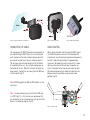
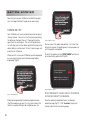
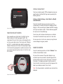
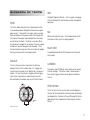
1
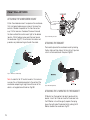
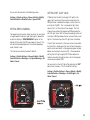
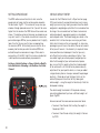
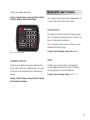
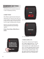
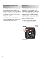
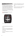
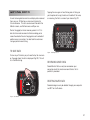
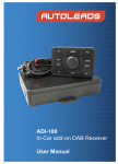
1
2
Table of Contents
Welcome to VI
7
Displayed Parameters
39
8
G Force Monitoring
40
Pack Contents 9
Saving Data
41
Product Overview
9
Welcome To Virtual Instrumentation
Operational Overview
11
Diagnostics Function
Warning
44
44
45
Operational Overview
12
Fault Codes
Function Modes
14
MIL Stats
Installation
Installation
17
18
43
Performance Function
Performance Function
47
48
Getting Started
21
Carrying out a Performance Run
48
Getting Started
22
Warning
48
Settings Menu
27
Carrying out a Dyno Measurement
51
Settings Menu
28
Lap Timing
52
Vehicle Settings
28
Viewing your Stats in the Performance Menu
53
System Settings
31
G Sensor Settings
32
Monitor Settings
33
Monitor Function
37
Monitor Function
38
Viewing and Manipulating your Downloaded Data 60
Presets
38
VI Desktop
55
Software Installation & Updating VI
56
Warning
56
Importing Data
58
3
Legal Information
Disclaimer
68
Warranty
69
Trademark
69
Copyright
69
Modifications
69
Declaration of Conformity
70
FCC Compliance Statement
70
Correct Disposal of this Product 70
Additional Information
FAQ’s
73
74
Troubleshooting
76
Glossary of Terms
77
Contact VI
79
Technical Help
79
Technical Specifications
80
Index
4
67
83
5
6
Welcome to VI
7
Welcome To Virtual Instrumentation
Thank you for purchasing a VI Monitor – one of the most advanced engine monitoring, diagnostic and performance data
correlation devices available. Please read through this manual fully before using your device to ensure you get the
maximum benefit from it.
VI Monitor will allow you to not only monitor data and engine functions normally only reserved for garages with expensive
diagnostic computers, but it will also allow you to check vehicle fault codes and reset them where applicable (see warning
on page 44).
Another major function of VI Monitor is to allow you to gauge your vehicles performance characteristics including G
measurements and timing readouts (not to be carried out on public roads).
With newer vehicles becoming more and more advanced, it is becoming less and less common to give the enthusiast the
data they want; VI Monitor gives you that data.
We are positive you will find VI Monitor useful, informative and fun but we urge you to use it in a sensible and controlled
environment. Please read the Disclaimer on page 68 before using your VI Monitor.
Please visit www.vi-performance.com for all the latest news and updates on VI products and visit our public forum to talk
with our experts and fellow users about your findings and results.
Please note that the performance features of VI Monitor have not been designed for use
whilst driving on public roads or highways and your use of VI Monitor is subject to the
“Legals” section (and partularly the Disclaimer) from page 67 onwards.
Thanks
Virtual Instrumentation
8
Pack Contents
Product Overview
Included in the box you should find:
VI Monitor is a highly sophisticated engine monitoring and
performance measuring device designed for modern cars
with sophisticated engine ECU systems.
• VI Monitor Main Control Unit
• OBD II Connector Cable
• Windscreen Suction Mount
• VI Monitor Bracket
• User Manual
• CD Rom
• USB Cable
• Virtual Instrumentation Window Sticker
If you find that any of the above items are not present,
please contact your supplier immediately before opening
any further packaging or using VI Monitor.
It works by collecting data via your vehicles original OBD
II port and then displaying that data on its high resolution
3.5” touch screen display.
Also built into VI Monitor is a highly accurate three axis ‘G’
sensor. This allows VI Monitor to display your longitudinal
and lateral G’s, and when used in partnership with the
OBD II information can also record performance statistics
for your vehicle including ¼ mile times and acceleration &
braking statistics.
Another feature that makes the VI Monitor such a useful
instrument is the built in diagnostic tool.
When your vehicles ECU detects an engine fault it can
illuminate the dashboard warning light to alert you. This
usually requires you to take your vehicle to a main dealer
for diagnosis and correction potentially costing a great
deal of money. With VI Monitor you can now diagnose
these faults on your own driveway. Armed with the
knowledge of what the fault is you can either take it to
the dealership for instant correction (saving yourself the
cost of diagnosis) or for the competent mechanic you
can correct the fault at home and then reset your engine
warning light (see warning on page 44).
9
10
Operational Overview
11
Operational
Overview
Fig.02 - Menu Structure
Most menus are displayed in a list format (Fig.02).
Should this list extend off the bottom of the screen you will
see two arrows at the lower edge of the screen (Fig.03)
which will allow you to scroll up and down to the other
menu items.
Fig.01 - Overview
VI Monitor is a very intuitive product and you will find that
most operations within the menus are self explanatory.
This overview will guide you through the initial powerup and generic functions of VI Monitor and review the
commonly used buttons and functions.
12
Fig.03 - Up & Down Arrows
You will notice that on many menus you will have a large
red arrow at the top left of the screen (Fig.04). This is
the back button which will take you to the previous screen.
Fig.04 - Back Arrow
Fig.06 - Save Button
On the Main Function Select screen (Fig.05) this will be
accompanied by a large red forward arrow which can be
used to scroll through the available options.
Fig.05 - Main Menu
To save any session or performance run data you should
press the disc icon (Fig.06).
This will save any recorded data to the relevant section for
future viewing or download.
13
Function Modes
Your VI Monitor has four main function modes which allow
you access to all the available menus and operations.
You can return to this screen at any time by repeatedly
pressing the ‘back arrow’.
Settings
This will take you to the menu where all adjustments to the
way VI Monitor works can be made, including calibration
and vehicle data.
Monitor
This is where you are able to monitor and customise the
displayed engine parameters.
Performance
This is where all the performance measuring options are
found including ¼ mile, 0-60-0 etc. You can also review
all your available peak recorded values here.
Diagnostics
In here you can find the tools to view and reset any engine
fault warnings you may have and also view your MIL stats.
(Please see warning on page 44)
The following chart details the full menu structure of your
VI Monitor.
14
Menu Flow Chart
OK
16
Installation
17
Installation
Attaching the Windscreen Mount
Attach the windscreen mount to a place on the windscreen
that is not going to obscure your vision or the use of any
controls. Remove the protective film from the suction
cup. Pull the lever near the base of the mount towards
the stem and hold the suction mount tight to the desired
location. Whilst holding in place push the lever toward
the windscreen (Fig.07), this will create the suction and
provide a very solid mounting surface for the cradle.
Fig.08 - Mounting Position
Attaching the Bracket
The bracket clips onto the windscreen mount by locating
the four slots and then sliding it to the right until you hear
a ‘click’ as the bracket locks into place (Fig.09).
Fig.07 - Windscreen Mounting
Note: In order for the ‘G’ function to work at its maximum
accuracy the unit should be mounted in the centre of the
windscreen and pointing straight toward the rear of the
vehicle - not angled toward the driver (Fig.08).
Fig.09 -Mounting Bracket
Attaching the VI Monitor to the bracket
VI Monitor has 3 connection tabs which locate onto the
bracket. Insert the 2 tabs on the left of the bracket into
the VI Monitor unit and then gently squeeze the spring
clip on the right side of the bracket whilst pushing the VI
Monitor towards the windscreen (Fig.10).
18
Fig.10 - Inserting VI Monitor onto Bracket
Fig.11 - Cable Connection
Fig.12 - OBD Plug Trimming
Connecting the cable
Cable Routing
The large plug on the OBD II Connector cable connects to
your vehicle’s original OBD II Plug (this is usually located
under the dash on the drivers side but please check with
your vehicle manufacturer if you are unable to locate it).
The small plug from the lead connects to the VI Monitor
at the bottom of the unit. You will find a sliding cover on
the bottom of the unit. Slide this to the left to reveal the
larger socket. Connect the small plug from the OBD lead
into this socket (Fig.11).
When routing the cable from the vehicle’s OBD II plug to
the VI Monitor device, ensure that the cable does not
interfere with any of the vehicle’s operational components,
and that it does not get pinched or trapped between
any panels. Be especially careful to ensure that it does
not hang in the driver’s foot well near the pedals, nor
that it is too close to the steering rack under the dash.
We recommend securing the cable with cable ties and
following the existing vehicle wiring harness where
possible (Fig.13).
Note: NEVER plug both the USB and OBD cables in at the
same time.
Note: On some vehicles you may find that the OBD plug
is a VERY tight fit. In this situation we recommend that
you remove the tab on the connector by cutting the 2 tabs
shown in the following diagram (Fig.12).
Fig.13 - Cable Routing
19
20
Getting Started
21
Getting Started
Now that you have your VI Monitor installed this chapter
will run through the basics to get you up and running.
Turning On / Off
Your VI Monitor will turn on automatically when you plug it
into your vehicle. You can turn it off manually by pressing
the button on the top of the unit. Pressing this button
again turns the unit back on. The unit will automatically
turn off when you turn the vehicle ignition off to ensure the
vehicle battery is not drained. To turn it back on again just
press the on / off button.
When you first turn on your VI Monitor you will be greeted
by a warning which you must read and accept before
proceeding (Fig.14).
Fig.15 - Update Screen
You can cancel this update and perform it at a later time
but you will receive this greeting every time you power up
until the update is completed.
To install the update just tap ‘UPDATE NOW’ and the unit
will automatically update itself (Fig.16).
UPDATING
VI is performing an update...
...Please be patient!
DO NOT unplug the VI during the
update, as this can damage the VI
Fig.16 - Update Progress
22
Fig.14 - Initial Warning
DO NOT DISCONNECT THE UNIT WHILST IT IS UPDATING
AS THIS CAN CORRUPT THE FIRMWARE.
Should you be greeted by the following Update screen
(Fig.15) on powering up your VI at any time it means that
there is an update waiting to be installed on your unit.
Once the update is completed the unit will display a
completion page (Fig.17). Click ‘Continue’ and you will
then be taken to the initial warning page.
VEHICLE DATA ENTRY
To set your vehicles weight, RPM and speed warnings you
need to enter the Vehicle Settings menu by pressing the
following buttons.
Settings > Vehicle Settings > Select Vehicle > Modify
Selected Vehicle.
Fig.17 - Update Complete
FUNCTION SELECT SCREEN
Once accepted you will be taken to the Main Function
Select screen on the Settings page (Fig.18). We
recommend that you firstly set your vehicle specific data
so that you are able to use all the functions of VI Monitor
and that it is customised to your specific requirements.
However should you wish to skip this step and go straight
into the monitoring, diagnostic or performance menu then
you may do so by pressing the arrows at the left or right
of the screen.
Once into the modify menu you can enter any of the
available details including the Scales for Speed and RPM,
Weight (in KG) and warnings for Speed and RPM (including
shift lights and redline values). Please reference page 28
for how to set all Vehicle Settings.
Once all your data has been entered you can customise
the name of the vehicle for easy access at a later date.
You may now return to the main screen by using the back
arrow and begin using your product.
MONITOR SCREEN
To use the monitoring section just select ‘Monitor’ from
the Main Function Select screen.
You can either view one of the preset displays or you
customise your own parameters by selecting one of the
custom presets using the small red arrows at the top of
the screen. To change a parameter tap the screen on
the on the dials, tap which dial you wish to change and the
select your chosen parameter from the list.
Note: Only the parameters available for your vehicle will be
displayed.
Fig.18 - Function Select Screen
23
Performance Function
In order to correctly use the Performance Tools you will
need to firstly calibrate your ‘G’ sensor. This is done by
entering the system menu.
Settings > G Sensor Settings > Calibrate G Sensor >
Calibrate.
Before carrying out this calibration please make sure you
have the Monitor fully mounted to the windscreen and that
the vehicle is on flat, level ground. Should the unit be relocated after this calibration has been done you will need
to re-calibrate it again to maintain accuracy.
To use the performance measuring section just enter the
Performance Menu from the Main Function Select screen
and tap whichever test you wish to carry out. (Page 48)
Diagnostic Function
To check your engine fault codes please go to the
diagnostics section from the Main Function Select screen.
24
25
26
Settings Menu
27
Settings Menu
In this menu you will find all the settings for adjusting and
setting up your VI Monitor. If you need to re-calibrate the
G sensor this is also found here along with the Factory
Reset command.
Modifying your chosen vehicles
specific settings
The currently selected vehicle will be highlighted red. To
modify this vehicle tap the ‘Modify Selected Vehicle’
button. You will then be taken to the Vehicle Settings
Modification menu.
Vehicle Settings
This is where you can adjust all settings relating to each of
the three vehicles that you are able to store data for. Also
in this menu are the warnings and scales settings which
again will be specific to each vehicle.
To access this menu:
Settings > Vehicle Settings > Vehicle 1 / 2 / 3
Once in this menu you have the option to select or modify
any of the three vehicles.
Selecting your chosen vehicle
To use all the stored data for a specific vehicle you must
tell VI Monitor that you wish to use this information. You
do this by selecting the chosen vehicle in the Vehicle
Settings menu.
Settings > Vehicle Settings > Vehicle 1 / 2 / 3 > Select
Vehicle
Once selected press ‘OK’ to confirm.
28
Setting the Monitor Scales
Each vehicle has different performance and power
bands so one scale would not suit all cars. This is most
predominant in RPM and Speed scales, for instance –
your car may have a maximum engine RPM of 6800rpm
but your friends diesel car may have a maximum RPM of
only 4900rpm and another friends race car may have a
maximum RPM of 8500rpm, all these values would not
be able to shown clearly on the same scale. To show the
data in the clearest manner possible we have given you the
choice to select the range that best suits your vehicle’s
RPM and Speed.
The available scales are as follows:
• RPM
o 0-5000rpm
o 0-7000rpm
o 0-9000rpm
• Speed
o 0-100mph
o 0-140mph
o 0-160mph
o 0-200mph
You can set these scales in the following manner
Setting Shift Light Value
Settings > Vehicle settings > Choose Vehicle > Modify
Selected Vehicle > Monitor Scales > Speed / RPM
VI Monitor has the ability to display shift lights in the
upper right hand area of the monitor screen when the
RPM paramter is selected for display in either the main
or small dial (Fig.20). This is a sequential light which
means that it will illuminate in three stages. The first
stage will be a yellow light appearing 500rpm below the
set shift light value. Next will be an orange light which will
illuminate at 200rpm below the set value and finally a red
light will illuminate when the shift light value is reached.
Setting Speed Warning
The speed warning function allows you to set an alert when
a target speed is reached. Upon reaching this speed the
screen will display a ‘SPEED WARNING’ caption at the
bottom of the screen (Fig.19) and a beep will sound. This
will continue to be displayed until the vehicle speed dips
under the alert value.
This function can also be turned off (default)
Settings > Vehicle Settings > Choose Vehicle > Modify
Selected Vehicle > Warnings > Set Speed Warning > Set
Value / Cancel
The shift light can be set at the same value as the redline
but note that in lower gears the revs will be climbing very
quickly which could result in the engine being over revved
before you have had a chance to shift. We recommend
setting the shift light roughly 300-700rpm below the
redline value when the redline value is set to the engines
maximum permissible RPM.
You can also turn the shift light off by selecting the ‘Off’
option from the menu. This is the default setting.
Settings > Vehicle Settings > Choose Vehicle > Modify
Selected Vehicle > Warnings > Set Shift Light > Set
Value / Cancel
Fig.19 - Speed Warning
Fig.20 - Shift Lights
29
Setting RPM Redline
Vehicle Weight Entry
The RPM redline value will dictate at what value the
gauge scale will move into the red zone when viewed on
the centre dial (Fig.21). This can be set to any value you
choose, although please be aware that if you set the value
higher than the scale on the RPM there will be no red area
shown. The redline can be set wherever you choose so you
may wish to set it at the vehicle manufacturer’s maximum
permissible engine RPM or you may decide to set it slightly
lower than that to warn you that you are approaching
the maximum RPM. Alternatively you can use this as an
economy tool to show you when the vehicle RPM’s are
outside the optimum economical range. When used in
conjunction with the Shift Light this can be a valuable tool
in both performance and economy improvements.
In order for the VI Monitor’s built in Dyno Function (page
51) to work correctly we need to know how much running
weight you are carrying. Ideally you would have the vehicle
weighed at a weighbridge, quite often this can be done free
of charge. You can sometimes find these at commercial
vehicle checkpoints, aggregate suppliers, or household
waste disposal sites. You should weigh your vehicle in the
condition that it will be when you are carrying out these
tests which is known as the running weight, i.e. how many
passengers you will have in the vehicle, the correct amount
of fuel you will have etc. You should try to replicate these
same conditions each subsequent time that you carry
out a Dyno Run to maintain consistency of data. If you
are unable to get your vehicle properly weighed you can
often find the weight of your vehicle online but please
bear in mind that this weight will be the standard weight
of the vehicle with a full tank of fuel so please make any
adjustments for your specific vehicle, i.e. have you added
a large stereo system or have you removed the passenger
seats etc. Please do not use the figure that is on the
vehicle ID plaque as this will be the fully laden gross
vehicle weight – using this weight will drastically inflate the
horsepower reading.
Settings > Vehicle Settings > Choose Vehicle > Modify
Selected Vehicle > Warnings > Set Redline > Set Value
/ Cancel
The vehicle weight is entered in KG so please make any
calculations beforehand if you have a different weight unit
figure (Fig.22).
Here are some of the more common conversion tables.
Fig.21 - Redline Area
• To convert from Pounds (lb’s) multiply the weight in
Pounds by 0.453
• To convert from Tonnes multiply the weight in Tonnes
by 1000.
30
To enter your vehicle’s weight click:
Settings > Vehicle Settings > Choose Vehicle > Modify
Selected > Weight > Enter Vehicle Weight
System Settings
This is where you can change the visual appearance of the
unit and is also where the main reset is found.
Factory Reset
This function will reset all the units’ settings and stored
data. This should only be used if you wish to clear the unit
back to its factory default conditions.
Note: If you carry out this function all vehicles, unit and
saved data will be lost or reset.
Fig.22 - Setting Vehicle Weight
Settings > System Settings > Factory Reset > Yes
Renaming Vehicles
Skins
This gives you the option to assign your chosen vehicle a
custom name to make future reference easy. You can do
this for each of the three vehicles that can be stored in
memory.
The Skins menu is there to allow future upgrades to
the visual appearance of your VI screens. The menu is
currently greyed out and cannot be selected.
Settings > System Settings > Skins > Skin 1 / 2 / 3
Settings > Vehicle Settings > Choose Vehicle > Modify
Selected Vehicle > Rename
31
G Sensor Settings
In this section you will find all adjustments relating to the
‘G’ sensor including damping and levelling.
Calibrate Sensor
When VI Monitor is moved from vehicle to vehicle you will
need to calibrate the ‘G’ sensor so that your results are as
accurate as possible. If you do not do this then VI Monitor
will display inaccurate readings. You should also calibrate
the unit if you move it to a different location in the vehicle.
Fig.24 - Calibrating ‘G’
Please wait until you see the calibration complete
notification appear before moving the vehicle again
(Fig.23-25).
Settings > G Sensor Settings > Calibrate G Sensor >
Calibrate
Fig.25 - ‘G’ Calibration Complete
‘G’ Sensor Damping Level
Fig.23 - ‘G’ Calibration Initiation
32
You may find that in vehicles with very stiff suspension
your ‘G’ readout may appear slightly erratic. This is due
to the fact that the VI Monitor’s ‘G’ sensor is a highly
sensitive acceleromter which is needed to display accurate
results. The ‘G’ sensor damping level allows you to remove
some of this erratic movement by delaying the number of
times that the display is updated every second. This will
give a smoother display but will compromise the update
speed slightly so you will find that the readout will be a
few milliseconds behind the vehicles movement. You have
four levels of damping available ranging from ‘Off’ to high
damping.
Settings > G Sensor Settings > G Damping > Off / Level
1/2/3
Monitor Settings
The Monitor Settings section contains all the options and
adjustments you can make to the monitor screen display.
Dial Damping Level
USE ‘G’ Sensor in Performance
The ‘G’ Sensor option can be used to trigger the start of
your Perfomance Tests for increased accuracy. This may
only be necessary if your vehicles’ OBD transfer rate is
not fast enough to trigger as soon as the vehicle starts
moving. In some cases this will be required if the vehicle
has had a speedo conversion applied.
This function is turned Off by default. To turn this function
on press:
Settings > G Sensor settings > Use G Sensor in
Performance > On / Off
In some vehicles you may find that the main dial display is
slightly juddery, this is due to the way that the data is sent
via your vehicles OBD Plug. In this case you can dampen
the needle so that it responds more smoothly but this
will have the consequence of making the response slightly
slower although during normal driving this will hardly be
apparent.
You have four available levels of adjustment ranging from
no damping to very high damping.
Settings > Monitor Settings > Dial Damping > Off /
Level 1 / 2 / 3
Dial Peak Hold
This function will initiate the peak hold needle on the
centre dial (Fig.26). This means that you will see a faint
red line which displays the instantaneous peak value
reached (the same as you see in the F1 coverage on TV).
This needle will show the peak value for a second or so and
then drop back to the current value until the vehicle needle
drops again, at which point it will show the new peak value.
Settings > Monitor Settings > Dial Peak Hold >
On or Off
33
The units available are:
• Speeds & Distances
• MPH
• KPH
• Imported Car (see section below)
• Temperatures
• Celsius
• Fahrenheit
Fig.26 - Peak Hold Needle
Units
You can change the units that certain parameters are
displayed in. These can all be changed in this menu.
There are three parameters that can be changed. Speeds
& Distances, Pressures and Temperatures.
This can be especially useful for travelling abroad where
the speed units can be changed to KPH and the warning
set accordingly to help avoid possible fines.
Settings > Monitor Settings > Units > Speeds &
Distances / Temperatures / Pressures
These unit settings will be saved for each individual car in
VI’s memory (settings will be saved to Vehicle 1 unless you
have selected an alternative vehicle)
• Pressures
• kPa
• BAR
• PSi
Imported Vehicles with speedo
conversions
The Imported Car option in the Speeds and Distances
setting is to allow certain vehicles that have been
imported and had a speedo conversion carried out to work
with VI Monitor. If you find that your speed readout is not
correct then please try using this option. Once ‘Imported
Car’ is selected it will remain highlighted and you must
then choose whether to display the speed in MPH or KPH.
This is not required for all imported vehicles so please try
this only if the normal setting does not work.
Settings > Monitor Settings > Units > Speeds &
Distances > Imported Car
34
35
36
Monitor Function
37
Monitor Function
Presets
The Monitor Function will allow you to monitor all the data
being sent from your vehicles ECU through the OBD II
connection in real time on the screen. Each parameter will
have its own scale already preset. Some of these are user
configurable and you will find this setting in the Vehicle
Settings section (Page 28).
You will see that at the top of the screen in the monitor
gauges display that there are three arrows. The two
smaller arrows are to allow you to scroll between different
preset gauge set-ups (Fig.27). Three of these presets
are factory set and cannot be changed (race, economy,
and ‘G’ Meter) but the three custom layouts can be set-up
to display any configuration you choose and these will be
saved by the unit for easy future access.
You are also able to change the units that certain
measurements adopt (temperatures, speeds & distances
and pressures) in the Units menu (Page 34).
Note: If your vehicle does not support the preset
parameters, these gauges will remain inactive.
Fig.27 - Monitor Presets
38
Displayed
Parameters
You can also turn off a gauge if you do not wish to display
any parameters on it by selecting the ‘No Display’ option
from the list.
To change a displayed parameter in a custom preset, just
tap the screen on any one of the 3 gauges (Fig.28). You
will then be taken to the gauge selection screen where
you must choose which gauge you wish to assign a signal
to. Tap which gauge you wish to customise. You will then
be taken to the parameter selection menu where all the
available parameters for that gauge will be displayed in a
list.
Monitor > Tap Gauge > Select Parameter
Note: Due to the nature of some parameters, you will only
be able to view certain types on the left hand (bar graph)
gauge.
Fig.28 - Parameter Selection
You can scroll up and down this list by using the up and
down arrows at the lower edge of this screen. When you
have decided on a parameter to select, just tap the screen
on that parameter and you will be returned to the gauge
monitoring screen
Note: Only the parameters available for your vehicle will be
displayed in this list.
39
G Force Monitoring
You will notice that the G Meter preset looks different
from the other guage displays and includes four numerical
readouts in addition to a crosshair display (Fig.29). The
red dot indicates the instantaneous G Force value and
direction, and the four numerical displays show the peak
‘G’ value on each axis. You can reset the peaks by tapping
the centre of the crosshair.
Note: Resetting this screen will NOT reset your Max
recorded ‘G’ Stats (page 53).
Fig.29 - G Meter Screen
In all G Force readouts please be aware of the following
definitions.
Acceleration ‘G’ is the G Force measured during vehicle
acceleration (the unit is tipped backwards towards the
rear of the vehicle)
Braking G Force is the opposite so the unit is effectively
tipped forward.
40
Left G Force is the force exerted on the unit in the left
direction so this will increase when the vehicle turns
RIGHT.
Right G Force is the force exerted in the Right direction
and increases when the vehicle turns LEFT.
Saving Data
As well as being able to monitor and display data received
from your car, VI Monitor can also save this data for
future reference. This data can be saved from both the
Monitor screen, and Performance and Dyno runs.
Tapping the icon again will end the log and will then give
you the option of saving the data as the default file name,
or renaming the file to a name of your choice (Fig.31).
Due to the gigabyte internal memory present in VI it is
able to store massive amounts of data enabling you to
record hundreds of hours of enging data and hundreds of
performance runs making it an ideal tool for endurance
racing or performance tuning.
To Save Data
To save any of this data you just need to tap the save icon
on the page where the data is displayed (Fig.30), This will
star the Monitor log.
Fig.31 - Labelling Screen
Reviewing Saved Data
Saved Monitor Data can only be reviewed on your
computer due to the massive amount of data that is
potentially recorded.
Deleting Saved Data
Saved datalogs can only be deleted through your computer
and NOT on the VI device.
Fig.30 - Save Button
41
42
Diagnostics Function
43
Fault Codes
Warning:
Before resetting any illuminated dashboard warning
lights, please check that the fault is fully corrected
and that there are no other associated faults that
could cause vehicle malfunction.
Please note that resetting your MIL can void your
warranty.
Note: Please be aware that only ENGINE fault
codes will be displayed on VI Monitor. Any fault
codes relating to braking, airbag or other safety
features will not be displayed on VI Monitor unless
they are displayed via the vehicle ENGINE diagnostic
light.
The Diagnostics Menu allows you to access your vehicle’s
engine ECU fault monitoring system via the OBD II plug. With this function you will be able to view any engine fault
codes that are present on your vehicle.
When your engine ECU detects an engine fault it can
trigger up your dashboard warning light. When you take
the car to a dealer to have this light investigated they will
connect their diagnostic computer to the vehicle and read
this fault code from your car’s engine ECU. This will then
allow them to correct the fault. With VI Monitor you can
now do all this yourself.
All fault codes will have an alphanumeric code assigned
to them. Each one of these codes represents a different
engine fault. If your vehicle has an engine fault present
not only will VI Monitor tell you this fault code but it will
also give you an explanation of that code allowing you the
potential to fix it yourself.
Note: Not all fault codes will have an explanation when
you tap them. This is due to the fact that only certain
codes are generic whereas there are many different
manufacturer specific codes. Only generic codes will be
listed descriptively.
Once you have found the fault code that has triggered your
fault light and rectified it, you can then proceed to reset
the warning light via the VI Monitor’s reset code function.
This diagnosis alone can cost up to £50 at some dealers.
Should the fault code re-appear again after being reset you
will know that either the problem has not been correctly
rectified or that there is another associated fault with the
engine.
44
To view fault codes
Diagnostics > View Fault Codes > View Description
(Tap alphanumeric code)
To Reset Fault Codes
Diagnostics > Reset Fault Codes > Yes
Note: Fault codes are reset in bulk which means that you
cannot choose which fault codes to specifically reset so
please be sure that all vehicle engine faults have been
rectified before the reset function is used.
Note: Only numbered fault codes up to 0199 will have
deccriptions. Any code above this is manufacturer specific
and will not be described by VI. For more information
on fault codes please visit the VI website at www.viperformance.com
MIL Stats
MIL Stats are data about the fault code recent history.
Included in these are the following stats.
Distance since MIL on – this allows you to view how far the
vehicle has been driven since the MIL was activated.
Minutes since MIL on – this allows you to view how long it
has been since the MIL was activated.
Distance since MIL cleared – this allows you to view how
far the vehicle has been driven since the MIL was last
reset.
Minutes since MIL clr – this allows you to view how long it
has been since the MIL was last reset.
Diagnostics > Mil Stats
Note: Not all vehicles are able to display MIL Stats.
45
46
Performance Function
47
Performance
Function
Warning:
All testing should be done on a private road or test
track and you should ensure that the road is as flat
as possible for safety and to maintain accuracy and
consistency.
In this section you will find all the tests for measuring the
performance of your vehicle.
In this menu you will find the tools for measuring your
vehicles acceleration and braking performance. Also you
will be able to track your vehicles ¼ mile times and in gear
acceleration figures. Additionally there is a dyno function
which will allow you to record your cars net horsepower
and will enable you to monitor the effect any changes you
make to your vehicle have on its performance (Fig.32).
Carrying out a
performance run
To complete one of the performance measuring runs you
will need to follow these instructions.
Make sure you have a long straight flat piece of road
to carry out testing on. Also please ensure you have
calibrated your G Sensor before commencing any tests.
Performance > Test Type > Start Test
Select which type of test you wish to carry out (0-60-0,
acceleration, ¼ mile, etc)
When you have selected the type of test, you will be taken
to the instruction screen. Press the left arrow to return
to the test selection screen if you wish to change the test
type or press the right arrow to go to the test screen.
When you have entered the test screen you will see the
‘OK’ button in the top right hand corner (Fig.33).
Fig.33 - Test Ready Screen
Fig.32 - Performance Menu Screen
48
Tapping this button will put VI Monitor into ‘test ready
mode’. It will be highlighted red until you bring the
vehicle to a complete halt at which point it will turn green
(Fig.34).
Fig.35 - Stop Screen
Fig.34 - Start Test
When the ‘OK’ icon has turned green this means that you
are ready to start the test. YOU DO NOT HAVE TO START
ACCELERATING IMMEDIATELY THE LIGHT TURNS GREEN.
VI Monitor will detect when you have started moving and
will start timing automatically.
Note: Should the device not start timing as soon as
you move, please see the Use G Sensor in Performance
section on page 33
When you are ready to start the test you should
accelerate as hard as possible until the test is completed.
In 0-??-0 tests the screen will flash up the words ‘STOP!
BRAKE NOW’ when you have reached the desired speed
(Fig.35), at which point you should bring the car to a
complete stop as quickly as possible.
You will notice the bar chart on the left hand side
increasing as you carry out your run. This is an indication
of how much of the run is completed and will not be
displayed in the acceleration menu.
Saving & Reviewing Results
Your results will be displayed on screen and are available
to save for future reference.
These results will show the time taken to reach the target
speed, the reaction time and then the time taken for the
vehicle to come to a complete stop. At the bottom you will
see the total time for all elements of the run.
In acceleration tests the device will stop recording either
when you tap the ‘OK’ button again or when your speed
reaches 100MPH (161KPH) at which time your results
will be displayed on screen. These results contain all your
0-?? times and in addition will also display your in gear
acceleration times i.e. 30-50 etc.
49
In ¼ mile mode the device will stop timing when you have
covered the full ¼ mile distance and it will then display
your results.
The ¼ mile time and speed will be displayed at the end
of the run. Also displayed will be the 1/8th mile time and
speed and also your 60ft time.
Deleting Saved Data
Saved performance runs can be deleted by tapping the ‘X’
icon in the performance file itself (Fig.37).
Any of these results can be saved using the save icon on
the right hand side of the screen and you can also assign
them a title at this time (Fig.36).
Fig.37 - Deleting Performance Datalog
Fig.36 - Labelling Screen
These results can be downloaded to your computer for
analysis with the VI Desktop application, or they can be
reviewed in the Stats Menu.
Performance > Stats > Saved Performance Files
50
Dyno Function
Lap Timing
You are able to measure your cars real time horsepower
in here. To activate the power gauge just tap the ‘DYNO’
function from the ‘Performance Menu’. This will display
the power gauge which will show your vehicle horsepower
being used in real time (Fig.38).
The VI Monitor has a built in lap timer function with split
times and best lap display (Fig.39).
Your peak value will be recorded in the ‘MAX STATS’ menu
(Page 52).
Before using this function you need to enter your vehicles
weight (Page 30) and also Calibrate the ‘G’ Sensor (Page
32)
Performance > Stats > Lap Timer > Stop / Reset / Start
You can use this feature to record one or a number of laps
completed. To start the timing, press the start button
on the right. To record the end of the lap, just tap the lap
icon and the unit will mark the lap and continue timing the
next lap. To stop timing and review all saved laps tap the
stop icon and timing will cease. To reset your lap times
and clear the display tap reset.
Performance>Dyno
Fig.39 - Lap Timer Screen
Fig.38 - Brake Horse Power Gauge
Once timing has been stopped, pressing start on the
display will automatically reset the times and start again
from zero. In the lap time’s list it will automatically show
your best lap since the last reset. You can view your
session laps on screen by using the up and down arrows at
the bottom of the screen. After 120 minutes the unit will
stop timing automatically.
51
Viewing your Stats
in the performance
menu
VI Monitor saves certain statistics in this menu which
are permanently updated automatically. These can
be reviewed and reset at any time by selecting the
appropriate function from the on screen menu.
Performance > Stats > Max Stats / Max G > View or
Reset
The Max Stats will record your maximum ever RPM and
Speed since the last reset and the Max ‘G’ will record the
highest ‘G’ settings seen by the unit in all directions since
the last reset. The Max ‘G’ function will record these
figures all of the time irrespective of which parameters
are being viewed in the Monitor screen. The Max Stats
(speed and RPM) will only be recorded when speed and
RPM are being monitored.
Note: When the unit is connected to the vehicle and
powered up, if you move it around by hand the unit will
continue to record Max ‘G’s which could exceed your
previous maximums.
52
53
54
VI Desktop
55
Software
Installation &
Updating VI
Main screen:
On opening the application you will be greeted with the
main screen which includes all options for manipulating
your data. (Fig.40)
Warning:
ONLY use the USB cable supplied with your VI
Monitor. DO NOT USE any other USB cable.
Included with your VI product is a CD containing the VI
Desktop application. This is the program that will allow
you to download and view your saved performance and
monitoring data from VI Monitor. It also serves as a
means of uploading new software updates to your VI
Device.
Note: This software is only compatible with Windows
operating systems.
Installing the software:
Insert the CD into your PC’s optical drive and navigate to it
via the ‘My Computer’ desktop icon.
Once you have opened the files on the CD you will see the
file labelled ‘VI Desktop.msi’. Double click this file and
the VI Desktop will begin to install. Follow the on screen
instructions to complete installation.
56
Fig.40 - VID Main Screen
Uploading Software Updates to your
Device:
When software updates are available for your device you
will be able to download them from the VI website www.viperformance.com. We recommend that before first using
your device you go to the website and check to make sure
that you have the latest software installed. You can check
your software version by clicking the ? icon at the top of
the VI Desktop Application.
If you need to download a new update you should click the
download software link on the website and save it to your
chosen location on your PC.
shown a final warning to NOT DISCONNECT THE DEVICE
during update which you must check before clicking next
once again to update your device.
Note: You will need to have registered your VI product via
the website in order to download software updates.
During the update process your device will display an
update screen (Fig.42) and when complete it will tell you
that it is restarting (Fig.43).
To install the update to your Device please click the ? icon
at the top of the VI Desktop. This will bring up your current
Device details and also at the bottom you have the ’Install
device s/w update’ option (Fig.41).
Fig.42 - Software Update Process
Fig.41 - Software Update Screen
Click this update button and you will be asked to locate
the update file on your PC. Navigate to the location you
saved the update and click ‘Next’. You will then be shown
what features are being updated. Click ‘OK’ and you will be
Fig.43 - Software Update Completed
Once the restart has finished and the update has been
installed you can disconnect the device.
57
Importing Data
To Import Data from the VI device with
the VI Desktop Application:
At the top of this screen you will see all VI devices
currently attached to the PC and also how much space is
remaining in the device’s memory.
First connect your VI Monitor to your PC using the
supplied USB lead. Your computer should automatically
recognise it as a Mass Storage Device and install
software automatically.
Whilst this is happening your VI device will be inoperable
and will display the following screen (Fig.44).
Fig.45 - Data Import Screen
Fig.44 - PC Link Screen
Once connected you can then proceed to import the files
onto your PC via the Desktop application.
At the top of the application you will see a bar chart icon.
Clicking this will take you to the Import Performance Data
screen (Fig.45).
58
The destination folder is the folder you would like all VI
downloaded data to be stored in your PC. You can change
this to any folder of your choice and the selection will
be the same next time you import files. To browse to a
certain folder on your PC just click the browse button and
navigate until you find your chosen folder.
You will also see two options under the browse folder
option.
•Leave performance files on the device – checking this
box will mean that when files are imported into the
chosen folder they will remain saved on the VI device
and will not be cleared. Should you uncheck this box,
when files are imported they will be wiped from the
device.
•Overwrite existing files – Checking this box means
that if you import a file with the same name as one
already stored in the target folder, the old file will
be overwritten by the new one. Unchecking this
box means that both files will remain and one will be
labelled as (file name) 2.
Once you have chosen your folder and have decided on the
two options you can click the ‘Import’ button at the bottom
of the screen. The application will then download ALL
stored files on the device into your chosen folder. Please
note that if you check the ‘Leave performance files on
device’ box and uncheck the ‘Overwrite existing files’ then
every time you download from VI you will be duplicating all
saved files.
then clicking the device icon that has appeared in your
‘My Computer’ folder. You will then see a list of files
and folders in the device folder. Double click on the
performance or datalog folder depending on which type
of file you wish to copy. You will then see a list of all files
currently on the device. Right click on your chosen file and
select copy and then paste the file wherever you wish on
your computer.
Note: You can open any of the saved CSV files in most
spreadsheet programs such as Excel but please be aware
that if ANY data is changed in the file, you will then not be
able to open this file in the VI Desktop Application.
If there are no files on the device then the application will
inform you of this.
Copying files from the VI device to
your computer without using the VI
Desktop Application:
Should you want to copy any saved performance or
monitoring files directly to your computer you can do
so by connecting the VI device to your computer and
59
Viewing and
manipulating your
downloaded Data
what parameters are displayed on the main screen.
•MI – Displays speed readouts in MPH
•KM – Displays speed readouts in KPH
At the very top of the screen you will find all the tools used
in the VI Desktop Application (Fig.46).
Fig.46 - VID Toolbar
•Zoom in - Zooms in on the main screen to allow closer
viewing of data.
•Zoom Out – Zooms out on the main screen to allow
more data to be viewed simultaneously.
•Cascade Windows – Cascades all open windows.
Starting from the left the functions are as follows.
•Open file – This allows you to open a saved file from
your PC to display in the VI Desktop.
•Compare – This allows you to compare up to four
PERFORMANCE files at one time
NOTE: Only Performance Files of the same type
can be compared; this function will not work with
Datalogs.
•Close – Closes the file currently being viewed.
•Import – Imports files from your VI Device to your
Computer
•Graph View – Shows the Data in graphical format.
•Chart View – Shows the Data in Chart format.
•Series Select – Allows you to re-order and specify
60
•Tile Windows – Tiles all open windows for
simultaneous viewing.
•Arrange Icons – When you minimise windows within
the VI Desktop you may find that if the main window is
re-sized these minimised icons will disappear. Clicking
this icon will re-arrange them at the bottom of your
screen.
•? – Shows any currently connected device information
and is also used for Device software updates.
Opening Datalog Files:
Ok, so now your data should be on your PC in your chosen
folder. You can now open these files in VI Desktop.
To open a new file click the folder icon at the top left of the
screen (or select open from the ‘File’ drop down menu).
You will then be asked to locate the file you wish to open.
Once located click open and the file display in VI desktop.
You will notice that the display is slightly different for
logged Monitor Data and Performance runs.
The screenshot below shows a Datalog file open in VI
Desktop (Fig.47).
Fig.48 - Datalog Max Values
Below this you will see a selection of tabs. These
represent all parameters that were recorded by the VI
device during your monitor session. You can click on any
of these to instantly view the selected parameter. If you
click on the All tab you will be able to view all recorded
parameters again.
If you only wish to display certain groups of parameters on
screen you can click on the series tab which will take you
to the series selection screen (Fig.49).
Fig.47 - VID Datalog Screen
Depending on how many parameters you recorded in your
logging session you will be able to scroll up and down the
graphs to view different parameters.
At the top of the Graph display you will notice that the
maximum values for each recorded parameter are
displayed (Fig.48).
Fig.49 - Datalog Series Selection
61
From this screen you can select or deselect as many
parameters as you wish. You can also change the order
they are displayed in the main window.
To change the order, just highlight the selected parameter
by clicking on the parameter name and then click move up
or move down as many times as you wish.
Once you are happy with your selection click OK to return
to the main screen.
Fig.50 - Datalog Chart View
You can zoom in on the display by using the zoom in or
zoom out icons. This will allow you to more closely analyse
the data.
Opening a Performance run:
You can view speed measurements in either KPH or MPH
and this selection will be remembered the next time you
open the VI Desktop. To do this just click the MI or KM
icon in the toolbar.
Performance runs are opened in the same manner as a
datalog file but they will only display three parameters
(Fig.51).
Should you wish to view the data in Chart format rather
than a graph click the chart icon at the top of the screen.
This view will provide numerical values at each recorded
time point for each parameter logged. Again you can use
the series select function to change the display order of
each parameter (Fig.50).
Fig.51 - Performance Run Data
62
The data in this file can be viewed and changed in the
same manner as the datalog type file.
Comparing Performance Files:
Once you have selected up to four files to compare click on
the ‘Compare’ button and the files will open in VI Desktop
(Fig.53).
With the VI Desktop Application you are able to compare
up to four performance files as long as they are of the
exact same type i.e. up to four 0-60-0 runs or up to four
¼ mile runs etc.
If you try and compare different types of runs you will
receive an error message.
You cannot compare Datalog Files in VI Desktop.
To open a comparison screen click on the second folder
icon from the left at the top of the screen. You will then
be shown the comparison file select screen (Fig.52).
Fig.53 - Run Comparison Screen
If you have previous file destinations already in these boxes
and you do not import a new one they will be compared
with any other files chosen. You can overwrite them by
selecting a new file or you can delete them and leave them
blank.
You will see that again you have the parameter tabs above
the graph and these can be selected to display any or all of
the available parameters. Once again the series selection
button can be used.
Fig.52 - Select Runs to Compare
At the top of the screen under the toolbar you will see a
different table. This table summarises all the compared
results and their performance statistics. The times
63
are arranged from quickest at the top to slowest at the
bottom. Each test is broken down into different sections.
In the above example you can see that there are four
parameters, 0-30, reaction, 30-0 and total. You can click
on the header tab for any of the sections and the chart will
automatically re-order to show the fastest at the top and
the slowest at the bottom.
The data from these performance runs can be viewed in
Chart format but this will not give you a comparison. To
select which of the compared runs is displayed in the chart
just click on run name at the top table.
64
65
66
Legals
67
Disclaimer
USE AT YOUR OWN RISK
VI MONITOR IS NOT DESIGNED TO BE USED ON PUBLIC
HIGHWAYS
Do not use this product until you have carefully read and
understood the following agreement. This sets forth the
terms and conditions for the use of this product. The
installation of this product indicates that the user has read
and understands this agreement and accepts its terms
and conditions. This agreement takes precedence.
Armour Automotive shall in no way be responsible for the
product’s proper use and serviceability.
THE BUYER HEREBY WAIVES ALL LIABILITY CLAIMS
Ensure you have read the manual in full and understood
it before using the VI Monitor. By using the VI Monitor
in any way you accept that, to the fullest possible extent
permissible by all applicable laws, Armour Automotive
hereby excludes and disclaims any and all warranties
concerning the VI Monitor (whether concerning its use,
fitness for purpose, functionality or otherwise). Further,
you accept that to the fullest extent permissible by all
applicable laws, Armour Automotive hereby excludes any
and all liability whatsoever and howsoever relating from
any death, personal injury, loss and or/damage arising
out of, pursuant to or in any way connected to the VI
Monitor or anyone’s use thereof. The user acknowledges
and agrees that the disclaimer of any liability for death,
personal injury, loss and or/damageis a material term for
this agreement and the user agrees to indemnify Armour
Automotive and to hold Armour Automotive harmless
68
from any claim related to VI Monitor. To the fullest extent
permissible by all applicable laws under no circumstances
will Armour Automotive be liable for any losses damages
or expenses by reason of use or sale of any such VI
Monitor and/or associated equipment. Armour Automotive
assumes no liability regarding the improper installation
or misapplication of VI Monitor. It is the responsibility
of the driver to secure VI Monitor so that it does not
interfere with the vehicles operating controls, obstruct
the drivers view, or cause death, personal injury, loss and
or/damage in the event of an accident. Do not mount VI
Monitor over air bag panels, which expand with a rapid
force that can propel objects in their path toward the
driver or passengers causing possible injury. Do not mount
VI Monitor in a place where the driver or passengers are
likely to impact in an accident or collision. The mounting
bracket is not warranted against collision damage or the
consequences thereof.
VI Monitor has been designed to be used on private roads
and the utmost care should be taken during use. It is the
sole responsibility of the driver of the vehicle to operate the
vehicle in a safe manner at all times in accordance with the
relevant conditions at the time and not become distracted
by VI Monitor to the exclusion of safe driving practices. It is
unsafe to operate the controls of VI Monitor while you are
driving. Failure by the driver of a vehicle equipped with VI
Monitor to pay full attention to the operation of the vehicle,
while the vehicle is in motion could result in an accident or
collision with property damage and personal injury.
Clearing vehicle Fault codes using the VI Monitor may
invalidate your vehicle warranty. You should consult with
your manufacturer before carrying out this function
Be sure to ONLY use the USB cable supplied with your VI
Monitor. DO NOT USE any other USB cable.
Warranty
Copyright
Armour Automotive warrants this product to be free
from defects in material and workmanship under normal
use for a period of 12 months from the date of original
purchase with receipt. Should service be necessary
under this warranty for any reason due to manufacturing
defect or malfunction during the warranty period, Armour
Automotive will repair or replace (at its discretion) the
defective merchandise with equivalent products. The
warranty excludes damage or abuse caused by customer
misuse or modification of the product in any way.
Copyright 2009; Armour Automotive. All rights reserved.
The total or even partial reproduction, transmission
or storage of this guide in any form or by any process
whatsoever (electronic, mechanical, photocopy, recording
or otherwise) is strictly prohibited without prior consent
from Armour Automotive.
All warranties are to be handled by the original retailer
where the goods were purchased.
This warranty is valid only for the original purchaser and
is not extended to owners of the product subsequent to
the original purchaser. Any applicable implied warranties
are limited in duration to a period of the express warranty
as provided herein beginning with the date of the original
purchase at retail, and no warranties, whether express or
implied, shall apply to this product thereafter.
Trademark
Modifications
The explanations and specifications in this guide are given
for information purposes only and may be modified without
prior notice. They are deemed to be correct at the time
of going to press. The utmost care has been taken when
writing this guide, as part of the aim to provide you with
accurate information. However, Armour Automotive shall
not be held responsible for any consequences arising from
any errors or omissions in the guide. Armour Automotive
reserves the right to amend or improve the product
design or user guide without any restrictions and without
any obligation to notify users.
All rights reserved. The VI trademarks are the sole
and exclusive property of Armour Automotive. Any
other trademarks or names used in VI documentation
are copyright protected and are the sole and exclusive
property of their respective owners.
69
Declaration of
Conformity
We, Armour Automotive of Bordon, Hampshire, UK hereby declare that the device described in this guide is
in compliance with the essential requirements and other
relevant provisions of the European Directive 1999/5/EC
(R&TTE). The declaration of conformity (DoC) concerned
has been signed.
Correct Disposal of
this Product
(Waste Electrical Electronic
Equipment)
This marking shown on the product or its literature,
indicates that it should not be disposed of with other
household wastes at the end of its working life. To prevent
possible harm to the environment or human health from
uncontrolled waste disposal, please separate this from
other types of wastes and recycle it responsibly to
promote the sustainable reuse of material resources.
Household users should contact either the retailer where
they purchased this product, or their local government
office. Business users should contact their supplier
and refer to the terms and conditions of the purchase
contract. This product should not be mixed with other
commercial wastes for disposals.
70
71
72
Additional Information
73
FAQ’s
My Dyno results are not the same as
my local ROLLING ROad:
The reason for the results differing from your local tuning
shop are that the VI Monitor works out ‘NET’ horsepower
whereas your tuning shop will work out the horsepower
@ the wheels and will also convert that to horsepower
@ the flywheel. Net horsepower is how much power
your car is generating in real world conditions i.e. the
amount of power your vehicle needed to accelerate it to a
measured speed at a measured G at any point, and will be
effected by factors such as wind resistance, vehicle weight
inaccuracies etc. A tuning shop dyno will not take these
into account.
My Drag strip results do not match my
times at the track.
This is most often caused by ‘rollout’. By this we mean
that when you are at a drag strip the time starts when
your wheels cross a certain fixed point on the track, this
can be after you have already started accelerating so you
could be doing maybe 2 or 3 mph or more. The VI Monitor
starts timing as soon as the vehicle moves meaning that
the times and speeds during the run can differ quite
considerably. Pitch factor can also cause some very minor
discrepancies but as long as the same conditions are used
from run to run you can still compare your times against
previous runs to gauge any improvements made.
74
My Speed readout does not match my
vehicle speedo.
It is very common for vehicle speedos to read slightly
optimistically and this can be up to 15%. This may be
built into the speedo itself and will be the reason that
the two values differ. VI Monitor reads the speed value
being provided by your vehicles engine ECU and displays it
directly without modification.
If you find that the reading is very inaccurate it may
be the case that your vehicle has had some type of
speedo correction device fitted (this is often the case
for imported cars). In some cases this will make the
ECU send out a corrected figure which is not the OBD II
standard. In this case please go to the units setting menu
(page 34) and select the imported vehicle setting and then
select your chosen unit (MPH or KPH).
I can drive my vehicle very slowly and
the speed readout on the VI Monitor
still displays zero.
This can be caused by the vehicle having some kind of
speedo conversion device fitted. This can cause a delay
in the signal being sent from the speed sensor to the
ECU and is the most likely cause of the VI not displaying
very very low speeds (normally below 3mph). This is
sometimes replicated by the vehicle speedo (drive very
very slowly and see if the vehicles speedo moves).
My Throttle position and/or
Accelerator position is never 0 or 100.
My RPM Needle movement is not
smooth.
VI Monitor displays the data that is sent to it from your
vehicle ECU. This may mean that your vehicle ECU is not
showing a fully open or closed throttle. Often this is for
idle control etc and to control fuelling at higher throttle
loads. It is very common for this to never show 100%
even though you have the accelerator pushed all the way
down.
This is caused by the data rate that your vehicle’s engine
ECU uses not being quick enough to update smoothly.
You can minimise this problem by turning off any unused
gauges (just having the RPM displayed will provide the
quickest response). You can also use the Dial Damping
function (page 33) to smooth out the needle movement.
My ‘G’ readouts in the ‘G’ Meter display
are back to front.
Acceleration ‘G’ is the G Force measured under vehicle
acceleration (the unit is tipped backwards towards the
rear of the vehicle).
Braking G Force is the opposite so the unit is effectively
tipped forward.
Left G Force is the force exerted on the unit in the left
direction so this will increase when the vehicle turns
RIGHT.
Right G Force is the force exerted in the Right direction
and increases when the vehicle turns LEFT.
75
Troubleshooting
Screen freezes
Unplug the unit for 30 seconds and then plug the unit back
into the vehicles OBD II Port.
Unit does not power up
Check that the connection at the vehicles OBD II plug and
the connection at the unit is fully inserted and has not
worked loose. Also check with your vehicle manufacturer
that your vehicle is OBD II compliant.
Unit powers up but does not receive
any data
Check check with your vehicle manufacturer that your
vehicle is OBD II compliant.
Unit powers up but only receives limited data
This is all of the data that your vehicle is transmitting that
VI Monitor can interpret.
Suction mount keeps falling off the
windscreen
Make sure you have removed the protective film on the
suction cup, make sure the windscreen has been cleaned.
Make sure that the windscreen area that the unit is
mounted on is not overly curved in shape (the suction cup
must be able to have an air tight contact with the screen.
76
I cannot drive with the OBD II lead plugged in as it interferes
Unfortunately we cannot control the manufacturers plug
location so in this instance you will be unable to use VI
Monitor safely.
I cannot find my OBD port
This is most commonly located under the dashboard
on the driver’s side, if it is not then please consult your
vehicle manufacturer for information.
Glossary of Terms
OBD:
Dyno:
On-Board Diagnostic System – This is a generic language
that the Vehicles ECU uses to communicate to diagnostic
equipment.
This is the abbreviated term for a Dynamometer which
is a piece of equipment designed to measure an engine’s
power output. There are 2 main types, one is an engine
Dyno and measures the power output of the engine only
and requires the engine to be removed from the vehicle
and tested on the bench. The other is a chassis Dyno
and measures the power of the vehicle at the cars wheels
so does not require the engine to be removed. This is
the most common type and is the usual choice for people
wanting to measure their cars power output.
MIL:
Malfunction Indicator Lamp – The dashboard light which
illuminates to alert you to an engine problem.
Fault Code:
The code displayed by the ECU to determine the type of
fault present.
Rollout:
This is a drag racing term and means the distance
between the cars front wheels when it is ‘staged’ and
the distance the vehicle will roll before the start beam is
broken. I.E. when the vehicle is staged and the staging
lights are on the vehicle can move forward a certain
distance before the wheels move out of the start beam.
G Sensor:
The sensor inside VI Monitor which allows you to monitor
G Force readings. This sensor takes it measurements
from measuring gravitational forces being imparted on
the unit.
Pitch Factor:
This is the term for the way the nose (and consequently
the rear) of the vehicle dives and raises under acceleration
and deceleration. Vehicles will have differing pitch factors
depending on their suspension stiffness along with other
factors.
Fig.54 - Roll Out
77
Lateral G’s:
Right G Force:
This is the force exerted on your vehicle when cornering
(left to right force) and is the forces that will cause you to
lean left or right.
This is the force exerted in the Right direction and
increases when the vehicle turns LEFT.
Longitudinal G’s:
This is the force exerted on your vehicle when you
accelerate or decelerate (forward and back force) and is
the force you will feel pushing you back into your seat.
G Damping:
The amount of smoothing imparted on the G sensor and
related Gauges.
Dial Damping:
Acceleration G:
The amount of smoothing applied to the Centre Dial.
This is the G force measured under vehicle acceleration
(the unit is tipped BACKWARDS towards the rear of the
vehicle).
Reaction Time:
This is the time taken between the screen flashing STOP
and you hitting the brakes.
Braking G:
This is the G Force measured under vehicle braking (the
unit is effectively tipped FORWARDS toward the front of
the vehicle) and this is measured in negative units.
Left G Force:
This is the force exerted on the unit in the left direction so
this will increase when the vehicle turns RIGHT.
78
Contact VI
Technical help
Web:
Web:
Visit www.vi-performance.com
www.vi-performance.com/tech or visit the forum to speak
to our tech experts.
Phone:
Armour Automotive on 01420 476767
Tech help line:
Technical line on 07825 247827
Tech help EMAIL:
[email protected]
79
Technical Specifications
80
Display
3.5" Colour TFT
Resolution
QVGA
System Processor
ARM9
Operating System
Microsoft CE
Vehicle i/o Processor
Freescale
Flash Memory
128Mb
Device i/o
Touch screen, USB
Vehicle i/o
CAN, J1850, ISO9141, Keyword 2000
Operating Temperature
0ºC ~ 70ºC
Operating Voltage
5.5V ~ 16V
Accelerometer
+/- 2.0 ‘G’
Dimensions
109mm x 79mm x 25mm
81
82
Index
83
Symbols
D
¼ mile 48, 50, 74
Datalog 60, 63
0-30-0 48
Deleting Data 41, 50
0-60-0 48
Diagnostics 14, 24
0-100-0 48
Dial Damping 33, 75, 78
Disclaimer 68
A
Disposal 70
Acceleration ‘G’ 40, 75, 78
Downloaded Data 59, 60
Accelerator Position 75
Dyno 30, 48, 51, 74, 77
Arranging Windows 60
E
B
Engine Fault 44
Back Button 12, 13
Braking G 40, 75, 78
F
Factory Reset 31
C
FAQ’s 74
Cable Routing 19, 76
Fault Codes 44, 77
Calibrating G Sensor 32, 48
Function Select Screen 23
Chart View 60, 62
Comparing Files 60, 63
Contact 79
G
G Meter 40, 75
Graphical View 60
84
G Sensor 32, 77
Menu Flow Chart 15
‘G’ Sensor Damping 32, 78
MIL Stats 45, 77
‘G’ Sensor in Performance 33
Modifying Vehicle Data 28
Monitor Scales 28
H
Monitor Section 14, 23, 38
Horsepower 51, 74
Monitor Settings 33
Mounting Bracket 18
I
Imported Vehicles 34, 74
O
Importing Data 58, 59, 60
OBD Cable 19, 76
Installing PC Software 56
OBD Connection 12, 76
OBD II Compliance 76, 77
L
On / Off Button 12, 22
Labelling Screen 41, 50
Lap Timing 51
P
Lateral G’s 78
Pack Contents 9
Left G 40, 75, 78
Parameters 23, 39, 61, 76
Longitudinal G 78
Peak Hold 33
Performance Data 49, 58, 62, 63
M
Performance Function 14, 24, 33, 48, 78
Max ‘G’ Stats 40, 52
Pitch Factor 74, 77
Max Stats 52
Presets 38
Max Values 61
85
R
Speed Scale 28, 34
Reaction Time 78
Speed Warning 29
Registering Your VI 57
System Settings 31
Renaming a Vehicle 31
Reset 76
T
Resetting Fault Codes 45
Technical Help 79
Reviewing Data 41
Technical Specifications 80
Right G 40, 75, 78
Throttle Position 75
Roll Out 74, 77
RPM Needle 75
U
RPM Redline 30
Units 34, 60, 62, 74
RPM Scale 28
Updates 22, 56, 60
Up / Down Arrow 12
S
USB Lead 58
Save Button 12, 13, 41
USB Socket 12
Saving Data 41, 49, 50
Selecting a Vehicle 28
V
Series Select 60
Vehicle Settings 23, 28
Settings Menu 14, 28
VI Desktop Application 41, 50, 56, 58, 60
Shift Light 29
Viewing Data 60
Skins 31
Viewing Results 49, 62
Speedo 74
86
W
Warnings 22, 44, 48, 56, 68
Warranty 69
Weight Entry 30
Windscreen Mount 18, 76
Z
Zoom 60, 62
87
VI Monitor is brought to you by Autoleads
a Brand of Armour Automotive
Woolmer Way | Bordon | Hampshire | GU35 9QE
All Rights Reserved 2009
Product and Specifications accurate at time of publication.
www.vi-performance.com